EP2556803A1 - Spine oriented indexing guide - Google Patents
Spine oriented indexing guide Download PDFInfo
- Publication number
- EP2556803A1 EP2556803A1 EP12164280A EP12164280A EP2556803A1 EP 2556803 A1 EP2556803 A1 EP 2556803A1 EP 12164280 A EP12164280 A EP 12164280A EP 12164280 A EP12164280 A EP 12164280A EP 2556803 A1 EP2556803 A1 EP 2556803A1
- Authority
- EP
- European Patent Office
- Prior art keywords
- guide
- drill
- sleeve
- drill guide
- cutting
- Prior art date
- Legal status (The legal status is an assumption and is not a legal conclusion. Google has not performed a legal analysis and makes no representation as to the accuracy of the status listed.)
- Granted
Links
- 239000007943 implant Substances 0.000 claims abstract description 100
- 238000003780 insertion Methods 0.000 claims abstract description 14
- 230000037431 insertion Effects 0.000 claims abstract description 14
- 125000006850 spacer group Chemical group 0.000 claims description 90
- 210000000988 bone and bone Anatomy 0.000 description 50
- 238000005553 drilling Methods 0.000 description 23
- 238000004873 anchoring Methods 0.000 description 15
- 210000001519 tissue Anatomy 0.000 description 14
- 230000001054 cortical effect Effects 0.000 description 12
- 238000000034 method Methods 0.000 description 12
- 230000013011 mating Effects 0.000 description 10
- 230000008878 coupling Effects 0.000 description 5
- 238000010168 coupling process Methods 0.000 description 5
- 238000005859 coupling reaction Methods 0.000 description 5
- 230000000295 complement effect Effects 0.000 description 4
- 238000001356 surgical procedure Methods 0.000 description 4
- 230000001045 lordotic effect Effects 0.000 description 3
- 230000001154 acute effect Effects 0.000 description 2
- 230000015572 biosynthetic process Effects 0.000 description 2
- 230000000399 orthopedic effect Effects 0.000 description 2
- 210000004872 soft tissue Anatomy 0.000 description 2
- 230000000712 assembly Effects 0.000 description 1
- 238000000429 assembly Methods 0.000 description 1
- 230000008901 benefit Effects 0.000 description 1
- 230000008859 change Effects 0.000 description 1
- 230000007423 decrease Effects 0.000 description 1
- 230000008676 import Effects 0.000 description 1
- 238000004519 manufacturing process Methods 0.000 description 1
- 230000008569 process Effects 0.000 description 1
- 230000002784 sclerotic effect Effects 0.000 description 1
- 238000010408 sweeping Methods 0.000 description 1
Images


Classifications
-
- A—HUMAN NECESSITIES
- A61—MEDICAL OR VETERINARY SCIENCE; HYGIENE
- A61B—DIAGNOSIS; SURGERY; IDENTIFICATION
- A61B17/00—Surgical instruments, devices or methods, e.g. tourniquets
- A61B17/16—Bone cutting, breaking or removal means other than saws, e.g. Osteoclasts; Drills or chisels for bones; Trepans
- A61B17/1662—Bone cutting, breaking or removal means other than saws, e.g. Osteoclasts; Drills or chisels for bones; Trepans for particular parts of the body
- A61B17/1671—Bone cutting, breaking or removal means other than saws, e.g. Osteoclasts; Drills or chisels for bones; Trepans for particular parts of the body for the spine
-
- A—HUMAN NECESSITIES
- A61—MEDICAL OR VETERINARY SCIENCE; HYGIENE
- A61B—DIAGNOSIS; SURGERY; IDENTIFICATION
- A61B17/00—Surgical instruments, devices or methods, e.g. tourniquets
- A61B17/16—Bone cutting, breaking or removal means other than saws, e.g. Osteoclasts; Drills or chisels for bones; Trepans
- A61B17/1604—Chisels; Rongeurs; Punches; Stamps
-
- A—HUMAN NECESSITIES
- A61—MEDICAL OR VETERINARY SCIENCE; HYGIENE
- A61B—DIAGNOSIS; SURGERY; IDENTIFICATION
- A61B17/00—Surgical instruments, devices or methods, e.g. tourniquets
- A61B17/16—Bone cutting, breaking or removal means other than saws, e.g. Osteoclasts; Drills or chisels for bones; Trepans
- A61B17/17—Guides or aligning means for drills, mills, pins or wires
- A61B17/1728—Guides or aligning means for drills, mills, pins or wires for holes for bone plates or plate screws
-
- A—HUMAN NECESSITIES
- A61—MEDICAL OR VETERINARY SCIENCE; HYGIENE
- A61B—DIAGNOSIS; SURGERY; IDENTIFICATION
- A61B17/00—Surgical instruments, devices or methods, e.g. tourniquets
- A61B17/16—Bone cutting, breaking or removal means other than saws, e.g. Osteoclasts; Drills or chisels for bones; Trepans
- A61B17/17—Guides or aligning means for drills, mills, pins or wires
- A61B17/1739—Guides or aligning means for drills, mills, pins or wires specially adapted for particular parts of the body
- A61B17/1757—Guides or aligning means for drills, mills, pins or wires specially adapted for particular parts of the body for the spine
-
- A—HUMAN NECESSITIES
- A61—MEDICAL OR VETERINARY SCIENCE; HYGIENE
- A61B—DIAGNOSIS; SURGERY; IDENTIFICATION
- A61B17/00—Surgical instruments, devices or methods, e.g. tourniquets
- A61B17/56—Surgical instruments or methods for treatment of bones or joints; Devices specially adapted therefor
- A61B17/58—Surgical instruments or methods for treatment of bones or joints; Devices specially adapted therefor for osteosynthesis, e.g. bone plates, screws, setting implements or the like
- A61B17/68—Internal fixation devices, including fasteners and spinal fixators, even if a part thereof projects from the skin
- A61B17/80—Cortical plates, i.e. bone plates; Instruments for holding or positioning cortical plates, or for compressing bones attached to cortical plates
- A61B17/8033—Cortical plates, i.e. bone plates; Instruments for holding or positioning cortical plates, or for compressing bones attached to cortical plates having indirect contact with screw heads, or having contact with screw heads maintained with the aid of additional components, e.g. nuts, wedges or head covers
- A61B17/8042—Cortical plates, i.e. bone plates; Instruments for holding or positioning cortical plates, or for compressing bones attached to cortical plates having indirect contact with screw heads, or having contact with screw heads maintained with the aid of additional components, e.g. nuts, wedges or head covers the additional component being a cover over the screw head
-
- A—HUMAN NECESSITIES
- A61—MEDICAL OR VETERINARY SCIENCE; HYGIENE
- A61F—FILTERS IMPLANTABLE INTO BLOOD VESSELS; PROSTHESES; DEVICES PROVIDING PATENCY TO, OR PREVENTING COLLAPSING OF, TUBULAR STRUCTURES OF THE BODY, e.g. STENTS; ORTHOPAEDIC, NURSING OR CONTRACEPTIVE DEVICES; FOMENTATION; TREATMENT OR PROTECTION OF EYES OR EARS; BANDAGES, DRESSINGS OR ABSORBENT PADS; FIRST-AID KITS
- A61F2/00—Filters implantable into blood vessels; Prostheses, i.e. artificial substitutes or replacements for parts of the body; Appliances for connecting them with the body; Devices providing patency to, or preventing collapsing of, tubular structures of the body, e.g. stents
- A61F2/02—Prostheses implantable into the body
- A61F2/30—Joints
- A61F2/44—Joints for the spine, e.g. vertebrae, spinal discs
- A61F2/442—Intervertebral or spinal discs, e.g. resilient
- A61F2/4425—Intervertebral or spinal discs, e.g. resilient made of articulated components
-
- A—HUMAN NECESSITIES
- A61—MEDICAL OR VETERINARY SCIENCE; HYGIENE
- A61F—FILTERS IMPLANTABLE INTO BLOOD VESSELS; PROSTHESES; DEVICES PROVIDING PATENCY TO, OR PREVENTING COLLAPSING OF, TUBULAR STRUCTURES OF THE BODY, e.g. STENTS; ORTHOPAEDIC, NURSING OR CONTRACEPTIVE DEVICES; FOMENTATION; TREATMENT OR PROTECTION OF EYES OR EARS; BANDAGES, DRESSINGS OR ABSORBENT PADS; FIRST-AID KITS
- A61F2/00—Filters implantable into blood vessels; Prostheses, i.e. artificial substitutes or replacements for parts of the body; Appliances for connecting them with the body; Devices providing patency to, or preventing collapsing of, tubular structures of the body, e.g. stents
- A61F2/02—Prostheses implantable into the body
- A61F2/30—Joints
- A61F2/44—Joints for the spine, e.g. vertebrae, spinal discs
- A61F2/4455—Joints for the spine, e.g. vertebrae, spinal discs for the fusion of spinal bodies, e.g. intervertebral fusion of adjacent spinal bodies, e.g. fusion cages
-
- A—HUMAN NECESSITIES
- A61—MEDICAL OR VETERINARY SCIENCE; HYGIENE
- A61F—FILTERS IMPLANTABLE INTO BLOOD VESSELS; PROSTHESES; DEVICES PROVIDING PATENCY TO, OR PREVENTING COLLAPSING OF, TUBULAR STRUCTURES OF THE BODY, e.g. STENTS; ORTHOPAEDIC, NURSING OR CONTRACEPTIVE DEVICES; FOMENTATION; TREATMENT OR PROTECTION OF EYES OR EARS; BANDAGES, DRESSINGS OR ABSORBENT PADS; FIRST-AID KITS
- A61F2/00—Filters implantable into blood vessels; Prostheses, i.e. artificial substitutes or replacements for parts of the body; Appliances for connecting them with the body; Devices providing patency to, or preventing collapsing of, tubular structures of the body, e.g. stents
- A61F2/02—Prostheses implantable into the body
- A61F2/30—Joints
- A61F2/46—Special tools or methods for implanting or extracting artificial joints, accessories, bone grafts or substitutes, or particular adaptations therefor
- A61F2/4603—Special tools or methods for implanting or extracting artificial joints, accessories, bone grafts or substitutes, or particular adaptations therefor for insertion or extraction of endoprosthetic joints or of accessories thereof
- A61F2/4611—Special tools or methods for implanting or extracting artificial joints, accessories, bone grafts or substitutes, or particular adaptations therefor for insertion or extraction of endoprosthetic joints or of accessories thereof of spinal prostheses
-
- A—HUMAN NECESSITIES
- A61—MEDICAL OR VETERINARY SCIENCE; HYGIENE
- A61F—FILTERS IMPLANTABLE INTO BLOOD VESSELS; PROSTHESES; DEVICES PROVIDING PATENCY TO, OR PREVENTING COLLAPSING OF, TUBULAR STRUCTURES OF THE BODY, e.g. STENTS; ORTHOPAEDIC, NURSING OR CONTRACEPTIVE DEVICES; FOMENTATION; TREATMENT OR PROTECTION OF EYES OR EARS; BANDAGES, DRESSINGS OR ABSORBENT PADS; FIRST-AID KITS
- A61F2/00—Filters implantable into blood vessels; Prostheses, i.e. artificial substitutes or replacements for parts of the body; Appliances for connecting them with the body; Devices providing patency to, or preventing collapsing of, tubular structures of the body, e.g. stents
- A61F2/02—Prostheses implantable into the body
- A61F2/30—Joints
- A61F2/46—Special tools or methods for implanting or extracting artificial joints, accessories, bone grafts or substitutes, or particular adaptations therefor
- A61F2/4684—Trial or dummy prostheses
-
- A—HUMAN NECESSITIES
- A61—MEDICAL OR VETERINARY SCIENCE; HYGIENE
- A61B—DIAGNOSIS; SURGERY; IDENTIFICATION
- A61B90/00—Instruments, implements or accessories specially adapted for surgery or diagnosis and not covered by any of the groups A61B1/00 - A61B50/00, e.g. for luxation treatment or for protecting wound edges
- A61B90/03—Automatic limiting or abutting means, e.g. for safety
- A61B2090/033—Abutting means, stops, e.g. abutting on tissue or skin
- A61B2090/034—Abutting means, stops, e.g. abutting on tissue or skin abutting on parts of the device itself
-
- A—HUMAN NECESSITIES
- A61—MEDICAL OR VETERINARY SCIENCE; HYGIENE
- A61F—FILTERS IMPLANTABLE INTO BLOOD VESSELS; PROSTHESES; DEVICES PROVIDING PATENCY TO, OR PREVENTING COLLAPSING OF, TUBULAR STRUCTURES OF THE BODY, e.g. STENTS; ORTHOPAEDIC, NURSING OR CONTRACEPTIVE DEVICES; FOMENTATION; TREATMENT OR PROTECTION OF EYES OR EARS; BANDAGES, DRESSINGS OR ABSORBENT PADS; FIRST-AID KITS
- A61F2/00—Filters implantable into blood vessels; Prostheses, i.e. artificial substitutes or replacements for parts of the body; Appliances for connecting them with the body; Devices providing patency to, or preventing collapsing of, tubular structures of the body, e.g. stents
- A61F2/02—Prostheses implantable into the body
- A61F2/30—Joints
- A61F2002/30001—Additional features of subject-matter classified in A61F2/28, A61F2/30 and subgroups thereof
- A61F2002/30316—The prosthesis having different structural features at different locations within the same prosthesis; Connections between prosthetic parts; Special structural features of bone or joint prostheses not otherwise provided for
- A61F2002/30317—The prosthesis having different structural features at different locations within the same prosthesis
- A61F2002/30324—The prosthesis having different structural features at different locations within the same prosthesis differing in thickness
-
- A—HUMAN NECESSITIES
- A61—MEDICAL OR VETERINARY SCIENCE; HYGIENE
- A61F—FILTERS IMPLANTABLE INTO BLOOD VESSELS; PROSTHESES; DEVICES PROVIDING PATENCY TO, OR PREVENTING COLLAPSING OF, TUBULAR STRUCTURES OF THE BODY, e.g. STENTS; ORTHOPAEDIC, NURSING OR CONTRACEPTIVE DEVICES; FOMENTATION; TREATMENT OR PROTECTION OF EYES OR EARS; BANDAGES, DRESSINGS OR ABSORBENT PADS; FIRST-AID KITS
- A61F2/00—Filters implantable into blood vessels; Prostheses, i.e. artificial substitutes or replacements for parts of the body; Appliances for connecting them with the body; Devices providing patency to, or preventing collapsing of, tubular structures of the body, e.g. stents
- A61F2/02—Prostheses implantable into the body
- A61F2/30—Joints
- A61F2/30767—Special external or bone-contacting surface, e.g. coating for improving bone ingrowth
- A61F2/30771—Special external or bone-contacting surface, e.g. coating for improving bone ingrowth applied in original prostheses, e.g. holes or grooves
- A61F2002/30795—Blind bores, e.g. of circular cross-section
- A61F2002/30805—Recesses of comparatively large area with respect to their low depth
-
- A—HUMAN NECESSITIES
- A61—MEDICAL OR VETERINARY SCIENCE; HYGIENE
- A61F—FILTERS IMPLANTABLE INTO BLOOD VESSELS; PROSTHESES; DEVICES PROVIDING PATENCY TO, OR PREVENTING COLLAPSING OF, TUBULAR STRUCTURES OF THE BODY, e.g. STENTS; ORTHOPAEDIC, NURSING OR CONTRACEPTIVE DEVICES; FOMENTATION; TREATMENT OR PROTECTION OF EYES OR EARS; BANDAGES, DRESSINGS OR ABSORBENT PADS; FIRST-AID KITS
- A61F2/00—Filters implantable into blood vessels; Prostheses, i.e. artificial substitutes or replacements for parts of the body; Appliances for connecting them with the body; Devices providing patency to, or preventing collapsing of, tubular structures of the body, e.g. stents
- A61F2/02—Prostheses implantable into the body
- A61F2/30—Joints
- A61F2/30767—Special external or bone-contacting surface, e.g. coating for improving bone ingrowth
- A61F2/30771—Special external or bone-contacting surface, e.g. coating for improving bone ingrowth applied in original prostheses, e.g. holes or grooves
- A61F2002/3082—Grooves
-
- A—HUMAN NECESSITIES
- A61—MEDICAL OR VETERINARY SCIENCE; HYGIENE
- A61F—FILTERS IMPLANTABLE INTO BLOOD VESSELS; PROSTHESES; DEVICES PROVIDING PATENCY TO, OR PREVENTING COLLAPSING OF, TUBULAR STRUCTURES OF THE BODY, e.g. STENTS; ORTHOPAEDIC, NURSING OR CONTRACEPTIVE DEVICES; FOMENTATION; TREATMENT OR PROTECTION OF EYES OR EARS; BANDAGES, DRESSINGS OR ABSORBENT PADS; FIRST-AID KITS
- A61F2/00—Filters implantable into blood vessels; Prostheses, i.e. artificial substitutes or replacements for parts of the body; Appliances for connecting them with the body; Devices providing patency to, or preventing collapsing of, tubular structures of the body, e.g. stents
- A61F2/02—Prostheses implantable into the body
- A61F2/30—Joints
- A61F2/30767—Special external or bone-contacting surface, e.g. coating for improving bone ingrowth
- A61F2/30771—Special external or bone-contacting surface, e.g. coating for improving bone ingrowth applied in original prostheses, e.g. holes or grooves
- A61F2002/30841—Sharp anchoring protrusions for impaction into the bone, e.g. sharp pins, spikes
- A61F2002/30845—Sharp anchoring protrusions for impaction into the bone, e.g. sharp pins, spikes with cutting edges
-
- A—HUMAN NECESSITIES
- A61—MEDICAL OR VETERINARY SCIENCE; HYGIENE
- A61F—FILTERS IMPLANTABLE INTO BLOOD VESSELS; PROSTHESES; DEVICES PROVIDING PATENCY TO, OR PREVENTING COLLAPSING OF, TUBULAR STRUCTURES OF THE BODY, e.g. STENTS; ORTHOPAEDIC, NURSING OR CONTRACEPTIVE DEVICES; FOMENTATION; TREATMENT OR PROTECTION OF EYES OR EARS; BANDAGES, DRESSINGS OR ABSORBENT PADS; FIRST-AID KITS
- A61F2/00—Filters implantable into blood vessels; Prostheses, i.e. artificial substitutes or replacements for parts of the body; Appliances for connecting them with the body; Devices providing patency to, or preventing collapsing of, tubular structures of the body, e.g. stents
- A61F2/02—Prostheses implantable into the body
- A61F2/30—Joints
- A61F2/30767—Special external or bone-contacting surface, e.g. coating for improving bone ingrowth
- A61F2/30771—Special external or bone-contacting surface, e.g. coating for improving bone ingrowth applied in original prostheses, e.g. holes or grooves
- A61F2002/30878—Special external or bone-contacting surface, e.g. coating for improving bone ingrowth applied in original prostheses, e.g. holes or grooves with non-sharp protrusions, for instance contacting the bone for anchoring, e.g. keels, pegs, pins, posts, shanks, stems, struts
- A61F2002/30884—Fins or wings, e.g. longitudinal wings for preventing rotation within the bone cavity
-
- A—HUMAN NECESSITIES
- A61—MEDICAL OR VETERINARY SCIENCE; HYGIENE
- A61F—FILTERS IMPLANTABLE INTO BLOOD VESSELS; PROSTHESES; DEVICES PROVIDING PATENCY TO, OR PREVENTING COLLAPSING OF, TUBULAR STRUCTURES OF THE BODY, e.g. STENTS; ORTHOPAEDIC, NURSING OR CONTRACEPTIVE DEVICES; FOMENTATION; TREATMENT OR PROTECTION OF EYES OR EARS; BANDAGES, DRESSINGS OR ABSORBENT PADS; FIRST-AID KITS
- A61F2/00—Filters implantable into blood vessels; Prostheses, i.e. artificial substitutes or replacements for parts of the body; Appliances for connecting them with the body; Devices providing patency to, or preventing collapsing of, tubular structures of the body, e.g. stents
- A61F2/02—Prostheses implantable into the body
- A61F2/30—Joints
- A61F2/44—Joints for the spine, e.g. vertebrae, spinal discs
- A61F2/442—Intervertebral or spinal discs, e.g. resilient
- A61F2/4425—Intervertebral or spinal discs, e.g. resilient made of articulated components
- A61F2002/443—Intervertebral or spinal discs, e.g. resilient made of articulated components having two transversal endplates and at least one intermediate component
Definitions
- the present application relates generally to methods and instruments for drilling multiple holes that are close together. More specifically the application discloses methods and instruments for maintaining a desired radial location and axial alignment of a drill bit while drilling overlapping holes in bone.
- drill bits In orthopedic surgery, drill bits have a tendency to skip or slide along the surface of a bone instead of boring into the bone as desired. This skipping or sliding is known as skiving. Skiving can alter the intended trajectory or position of a hole that is drilled into the bone.
- a drill guide can be used in some situations to help control the radial location and axial alignment of a drill bit.
- drill guides are typically limited to a single location and orientation to a desired datum.
- a channel is cut into a bone.
- a channel can be cut into a vertebra of a spinal column.
- the channel is configured to receive an anchoring structure of an implant, such as a keel, to secure the implant within the spinal column.
- an implant such as a keel
- a side-cutting drill can be used in a sweeping fashion to remove a channel of bone.
- harder sclerotic bone as is often found in the lumbar of the spine, the use or effectiveness of a side-cutting drill bit may be limited.
- a series of partially overlapping, in-line drill holes may be used to approximate the channel cut. The potential for drill skiving is magnified during a procedure that involves the drilling of sequential holes that are either overlapping or located close together, because the drill bit has a tendency to skive into previously drilled holes.
- Traditional drill guides can be used to help control the location and alignment of a drill bit during a single hole drilling operation; however, they do not allow sufficient control of the location and orientation of several sequential drill holes that are either overlapping or located close together.
- the surgical cutting system generally includes a drill guide, a drill guide sleeve, and a drill bit.
- the drill guide can be configured to be coupled to a trial implant, and includes a guide portion. Further, the drill guide can define a guide hole that extends through the guide portion along a guide hole axis.
- the drill guide sleeve can be configured to be at least partially received in the guide hole, and includes a sleeve body.
- the drill guide sleeve defines a first stop member and a sleeve opening disposed through the sleeve body.
- the drill bit can be configured to be at least partially received in the sleeve opening.
- the drill bit defines a second stop member that is configured abut the first stop member so as to limit movement of the drill bit through the guide hole along the guide hole axis to a maximum cut depth.
- the guide hole can be oriented relative to the trial implant when the drill guide is coupled to the trial implant such that the guide hole is configured to guide the drill bit to advance through the guide hole along the guide hole axis into the vertebral body so as to create a drilled opening in the vertebral body.
- the drilled opening can be elongate along a drill axis that is substantially parallel to at least a portion of an upper surface or a lower surface of the trial implant.
- the drill guide can further include a first spacer member and a second spacer member that is spaced from the first spacer member, the first and second spacer members elongate along a longitudinal direction, and the first and second spacer members spaced from each other along the transverse direction that is substantially perpendicular to the longitudinal direction, and the first and second spacer members are configured to engage corresponding first and second opposed surfaces of the trial implant.
- the guide hole axis is angularly offset with respect to the longitudinal direction, such that the drilled opening extends along a trajectory that is angularly offset with respect to the longitudinal direction.
- the drill guide can further include a drill guide body that extends from the guide portion along the longitudinal direction.
- the guide portion can protrude from the drill guide body along the transverse direction.
- the drill guide can define a drill guide opening that extends into the drill guide body.
- the drill guide opening can be configured to receive at least a portion of the trial implant such that insertion of the portion of the trial implant in the drill guide body opening causes the drill guide to be coupled to the trial implant.
- the drill guide opening can be elongate along the longitudinal direction.
- the surgical cutting system can further include a drill guide sleeve that is configured to be at least partially received in the guide hole.
- the drill guide sleeve can include a sleeve body. Further, the drill guide sleeve can define a sleeve opening disposed through the sleeve body. The sleeve opening can be configured to receive at least a portion of the drill bit.
- the drill guide sleeve can define the first stop member, and the second stop member is configured to contact the first stop member so as to define a cut depth that is substantially equal to an insertion depth of the chisel into the vertebral body.
- the drill guide can include a plurality of first engagement members that at least partially define the guide hole.
- the drill guide sleeve can define a plurality of second engagement members that are configured to mate with the first engagement members so as to couple the drill guide sleeve to the drill guide.
- the first engagement members can be lobes that protrude from the guide portion into the guide hole.
- the second engagement members can be splines defined along at least a length sleeve of the sleeve body, the splines configured to mate with the lobes so as to couple the drill guide to the drill guide sleeve.
- the guide hole can define a first portion and a second portion.
- the first portion defines a transverse dimension greater than the second portion.
- the drill guide sleeve can be sized to be inserted into the first portion, and is sized greater than the second portion.
- the drill guide sleeve can be at least one first drill guide sleeve sized to be inserted into the first portion, and the surgical cutting system further comprises at least one second drill guide sleeve sized to be inserted into the second portion.
- the first drill guide sleeve can define an internal diameter greater than that of the at least one second drill guide sleeve.
- the drill bit can be a first drill bit, and the surgical cutting system can further include a second drill bit having a smaller diameter than the first drill bit.
- the second drill bit can be sized to be guided through the at least one second drill guide sleeve.
- the second drill bit can define a stop member that is configured abut a complementary stop member supported by the guide portion so as to limit movement of the second drill bit through the guide hole along the guide hole axis, such that the second drill bit defines a maximum cut depth less than that of the first drill bit.
- the second drill bit can be configured to be guided along the second drill guide sleeve into a vertebral body, and the maximum cut depth of the second drill bit is greater than a thickness of a cortical wall of the vertebral body.
- the drill guide can include a plurality of first engagement members that at least partially define the guide hole.
- the second drill guide sleeve can include a pair of drill guide sleeve.
- One of the pair of drill guide sleeves has a substantially smooth outer surface and the other of which defining a plurality of second engagement members configured to interlock with at least one of the plurality of first engagement members.
- the second drill guide sleeve can be configured to slide along the guide hole in the transverse direction without interlocking with the first engagement members.
- the second drill guide sleeve can have the substantially smooth outer surface defines an outer diameter sized less than a cross-sectional dimension of the guide hole as measured through at least one of the first engagement members.
- the surgical cutting system can further include a connection member connected between each of the pair of the at least one second drill guide sleeve.
- the first sleeve body can define a first cross-sectional dimension
- the second sleeve body defines a second cross-sectional dimension that is less than the first cross-sectional dimension.
- the surgical cutting system can further include the trial implant that includes a support member and a trial spacer member that is connected to the supporting member.
- the trial spacer member can be sized to be inserted in an intervertebral space between adjacent vertebral bodies.
- the guide hole can be a first guide hole, and the guide member can define a second guide hole spaced from the first guide hole, such that the first guide hole is configured to be aligned with a first vertebral body.
- the second guide hole can be configured to be aligned with a second vertebral body, such that the trial implant is configured to be inserted into an intervertebral spaced defined between the first and second vertebra bodies.
- the surgical cutting kit includes a trial spacer member, a drill guide, a drill guide sleeve, and a drill bit.
- the trial spacer member can be sized to fit in an intervertebral space between first and second vertebral bodies, the trial spacer member defining an upper surface and a lower surface opposite the upper surface.
- the drill guide can be configured to be fixed with respect to the trial spacer member.
- the drill guide can include a guide portion.
- the drill guide can define a guide hole that extends through the guide portion along a guide hole axis.
- the drill guide sleeve can be configured to be at least partially received in the guide hole, and includes a sleeve body.
- the drill guide sleeve defines a sleeve opening disposed through the sleeve body.
- the drill bit can be configured to drill through the vertebral bodies.
- the drill bit can be configured to be at least partially received in the sleeve opening and guided through the guide hole along the guide hole axis so as to create a drilled opening in the first vertebral body.
- the guide hole can be oriented relative to the trial spacer member when the drill guide is fixed with respect to the trial spacer member such that the drilled opening is in substantial alignment with the upper cutting edge of the chisel when the chisel is guided along the trial spacer member and into the first vertebral body.
- Fig. 1 A is a perspective view of a surgical cutting system according to an embodiment of the present disclosure that includes a trial disc implant partially disposed in an intervertebral space between first and second vertebral bodies, a cutting guide, a first guide member, a first cutting tool, a second guide member, and a second cutting tool;
- Fig. 1B is a posterior view of a vertebral body of the partial spinal column shown in Fig. 1 A having an upper deep hole that extends into the cancellous bone of the vertebral body;
- Fig. 1C is a medical elevation view of the vertebral body of Fig. 1B , showing the upper deep hole that extends into the cancellous bone;
- Fig. 1D is a posterior view of the vertebral body of Fig. 1B having a plurality of shallow holes that extend at least into the cortical bone of the vertebral body;
- Fig. 1E is a medial view of the vertebral body of Fig. 1D , showing the shallow holes that extend at least into the cortical bone of the vertebral body;
- Fig. 1F is a posterior view of the vertebral body of Fig. 1B , showing the upper deep hole that extends into the cancellous bone and a plurality of overlapping shallow holes that extend into at least into the cortical bone;
- Fig. 1 G is a medial view of a partial spinal column, showing the trial disc implant of Fig. 1A disposed between adjacent vertebral bodies and a chisel inserted into the spinal column;
- Fig. 1H is a posterior view of an intervertebral implant disposed in an intervertebral space between adjacent vertebral bodies;
- Fig. 2 is a perspective view of the trial disc implant shown in Fig. 1A ;
- Fig. 3A is a perspective view of the cutting guide shown in Fig. 1A ;
- Fig. 3B is a side cross-sectional view of the cutting guide of Fig. 3A , taken along section line 3B-3B;
- Fig. 3C is a front elevation view of the cutting guide of Fig. 3A ;
- Fig. 4A is a perspective view of the guide member shown in Fig. 1A ;
- Fig. 4B is a side cross-sectional view of the guide member of Fig. 4A , taken along the section line 4A-4A;
- Fig. 5A is perspective view of the second guide member of Fig. 1A ;
- Fig. 5B is a side cross-sectional view of the second guide member of Fig. 5A , taken along section line 5B-5B;
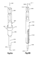
- Fig. 6 is a perspective view of the first cutting tool shown in Fig. 1A ;
- Fig. 7 is a perspective view of the second cutting tool shown in Fig. 1A ;
- Fig. 8 is a side elevation view of the first cutting tool shown in Fig. 1A partially inserted in a first guide member sleeve of the first guide member shown in Fig. 1A ;
- Fig. 9 is a side elevation view of the second cutting tool shown in Fig. 1A partially inserted in a second guide sleeve of the second guide member shown in Fig. 1A ;
- Fig. 10A is a perspective view of a bone anchor of the surgical cutting system shown in Fig. 1A ;
- Fig. 10B is a perspective view of another bone anchor of the surgical cutting system shown in Fig. 1A ;
- Fig. 11 is a perspective view of the third cutting tool shown in Fig. 1G ;
- Fig. 12A is a side elevation view of a partial spinal column and the trial disc implant shown in Fig. 1A at least partially disposed in an intervertebral space between adjacent vertebral bodies;
- Fig. 12B is a side elevation view of the partial spinal column and the trial disc implant illustrated in Fig. 12A , and the cutting guide shown in Fig. 1A coupled to the trial disc implant;
- Fig. 12C is a side elevation view of the partial spinal column, the trial disc implant, and the cutting guide shown in Fig. 12B , and the first guide member and the first cutting tool shown in Fig. 1A , wherein the trial disc implant and the cutting guide are in a first position relative to the intervertebral space;
- Fig. 12D is a side elevation view of the partial spinal column, the trial disc implant, and the cutting guide shown in Fig. 12B , and the first guide member and the first cutting tool shown in Fig. 1A , wherein the trial disc implant and the cutting guide are in a second position relative to the intervertebral space;
- Fig. 12E is a side elevation view of the partial spinal column, the trial disc implant, the cutting guide, the first guide member, and the first cutting tool illustrated in Fig. 12C , and the second guide member and the second cutting tool shown in Fig. 1A ;
- Fig. 12F is a side elevation view of the partial spinal column, the trial disc implant, the cutting guide, the second guide member, and the second cutting tool, and a superimposed image of the third cutting tool shown in Fig. 1A .
- a surgical cutting system 10 is configured to prepare an intervertebral space for inserting a suitable intervertebral implant.
- the surgical cutting system 10 can be a surgical drilling system.
- the surgical cutting system 10 can be used to prepare an intervertebral space for inserting an intervertebral implant 700 that includes at least one keel 702 that is configured to be inserted into a first vertebral body V1 or a second vertebral body V2 of a spinal column S.
- Examples of a suitable intervertebral implant is described and illustrated in U.S. Patent No. 6,936,071 issued on August 30, 2005 , the entire disclosure of which is herein incorporated by reference.
- the surgical cutting system 10 can be part of a surgical disc replacement assembly that can be used for total disc replacement surgery.
- a diseased or degenerated intervertebral disc can be replaced with a suitable intervertebral implant, such as the intervertebral implant 700.
- the surgical disc replacement assembly can include the surgical cutting system 10 and one or more intervertebral implants 700.
- the surgical cutting system 10 can include a trial disc implant 100, a cutting guide 200, a first guide member 300, a second guide member 400, a first cutting tool 500, and a second cutting tool 600.
- the first cutting tool 500 can be a first drill bit 502.
- the second cutting tool 600 can be a second drill bit 602.
- the trial disc implant 100 can include a trial spacer member 102 that is sized to be disposed in an intervertebral space between the first vertebral body V1 and the second vertebral body V2.
- the cutting guide 200 can be configured to be coupled to the trial disc implant 100, and can define one or more guide holes.
- the cutting guide 200 defines a first guide hole 202 and a second guide hole 204.
- Each guide hole 202, 204 can be configured to receive at least a portion of the first guide member 300 or at least a portion of the second guide member 400.
- the cutting guide 200 can be configured as a drill guide.
- the drill guide can be configured to be coupled to the trial implant 100.
- the first cutting tool 500 can be configured to be at least partially received in the first guide hole 202 or the second guide hole 204.
- the first drill bit 502 can be configured to be at least partially received in the first guide hole 202 or the second guide hole 204.
- the second cutting tool 600 can be configured to be at least partially received in the first guide hole 202 or the second guide hole 204.
- the first drill bit 602 can be configured to be at least partially received in the first guide hole 202 or the second guide hole 204.
- the trial disc implant 100 can be placed in the intervertebral space between the first vertebral body V1 and the second vertebral body V2 to determine the appropriate implant footprint, lordotic angle, and disc height of the intervertebral implant 700 ( Fig. 1H ).
- the surgical cutting system 10 can include a plurality of trial disc implants 100 with spacer members 102 of different shapes and sizes.
- the cutting guide 200 can be coupled to the trial disc implant 100 that is at least partially disposed in the intervertebral space such that the first and second guide holes 202 and 204 are aligned with at least one of the first vertebral body V1 or the second vertebral body V2.
- the cutting guide 200 can be coupled to the trial implant 100 such that the first guide hole 202 is aligned to the first vertebral body V1 and the second guide hole 204 is aligned with the second vertebral body V2. At least a portion of the first guide member 300 can be disposed through the first guide hole 202. Once the first guide member 300 is disposed through the first guide hole 202, the first cutting tool 500 can be advanced through the first guide member 300 and into the first vertebral body V1 to fix the position of the cutting guide 200 relative to the spinal column S. At least a portion of the second guide member 400 can be inserted through the second guide hole 204.
- the second cutting tool 500 can then be advanced through the second guide member 400 and into second vertebral body V2 to create a first opening 1 ( Figs. 1B-C ) that extends into through the cortical bone and into the cancellous bone of the first vertebral body V1.
- the second cutting tool 500 can have a substantially rounded, such as circular, semi-circular, or oval, cross-sectional shape such that it can create a first opening 1 that defines a substantially rounded cross-sectional shape.
- the second guide hole 204 can be oriented relative such that the second cutting tool 600 moves along a trajectory that matches the trajectory that will following a third cutting tool 800, such as a chisel 802 ( Fig. 1G ).
- the third cutting tool 800 ( Fig. 1 G) can be advanced along the trial disc implant 100 and into the first vertebral body V1 and the second vertebral body V2 to create one more apertures that are configured to receive one or more keels 702 of the intervertebral implant 700.
- the cutting guide 200 (e.g., the drill guide) can be configured to support a first stop member 314 (or 316 as seen in Fig. 4A ) as discussed in detail below.
- the cutting tool 500 such as the drill bit 502
- the cutting guide 200 (e.g., the drill guide) can be configured to support a first stop member 414 (or 416 as seen in Fig. 5A ) as discussed in detail below.
- the cutting tool 600 such as the drill bit 602 can define a complementary second stop member 618 that is configured to abut the first stop member 414 (or 416) so as to limit movement of the cutting tool 600 (e.g., drill bit 602) through the guide hole 202 (or 204) to a maximum cut depth.
- the first opening 1 can be elongate along a first cutting axis 2 that is substantially aligned with the trajectory that follows an edge of the third cutting tool 800 ( Fig. 1 G) when the third cutting tool is advanced along the trial disc implant 100 and into the second vertebral body V2.
- the first opening 1 defines a first closed end 3 that is disposed in the cancellous bone of the second vertebral body V2, and a second open end 4 that is located at the cortical bone of the second vertebral body V2.
- the first closed end 3 is spaced from the second open end 4 in a direction along the cutting axis 2.
- the cutting axis 2 can also be a drill axis.
- the second open end 4 leads to the exterior of the second vertebral body V2.
- the first opening 1 can have a substantially rounded, such as circular or oval, cross-sectional shape to prevent, or at least inhibit, the formation of stress risers in the second vertebral body V2, thereby precluding, or at least hindering, the creation of stress cracks in the second vertebral body V2. It is envisioned that an opening can also be created in the first vertebral body V1 that is substantially aligned with the trajectory that follows another edge of the third cutting tool 800 ( Fig. 1G ).
- the second cutting tool 600 can also be used to remove portions of the cortical bone of the second vertebral body V2 to facilitate advancement of the third cutting tool 800 ( Fig. 1G ) into the vertebral body V2 as discussed in detail below.
- the second cutting tool 600 can be moved along the second guide hole 204 to create one or more second openings 5 that extend at least into the cortical bone of the second vertebral body V2.
- Each of the second openings 5 can define a second cutting axis, such as the second cutting axis 6.
- Each of the second cutting axes 6 can be oriented at an oblique angle relative to the first cutting axis 2.
- the second cutting axes 6 can be substantially parallel to each other.
- the second openings 5 are substantially aligned along the cranial direction C1 and the caudal direction C2 of the second vertebral body V2. Furthermore, the second openings 5 can define cutting axes that are substantially parallel to one another. Each of the second openings 5 can define a first closed end 7 that can be disposed in the cortical wall of the second vertebral body V2, and a second open end 8 that leads to the exterior of the second vertebral body V2. The first closed end 7 can be spaced from the second open end 8 along the second cutting axis 6. It is envisioned that the second openings 5 can also be created in the first vertebral body V1 using the cutting tools described in the present disclosure. The openings 5 can overlap with one another as shown in Fig.
- the openings 5 are created to remove additional cortical wall after making the opening 1 to thereby facilitate insertion of a cutting tool through the vertebral bodies.
- the openings 5 can extend all the way to the endplate of the vertebral body V2. However, it is envisioned that the openings 5 do not necessarily extend to the endplate of the vertebral body V2.
- the cutting guide 200, the first cutting guide 200, the first guide member 300, the second guide member 400, the first cutting tool 500, and the second cutting tool 600 can be removed from the patient, while leaving the trial spacer member 102 of the trial disc implant 100 disposed in the intervertebral space between the first vertebral body V1 and the second vertebral body V2.
- the third cutting tool 800 can be a chisel 802, and is configured to cut bone, such as the first vertebral body V1 and the second vertebral body V2.
- the third cutting tool 800, such as a chisel 802 can then be advanced along the trial disc implant 100 and toward the first vertebral body V1 and the second vertebral body V2.
- third cutting tool 800 can be advanced into the first vertebral body V1 and the second vertebral body V2 to create a first aperture 9 ( Fig. 1H ) in the first vertebral body V1 and a second aperture 11 ( Fig. 1H ) in the second vertebral body V2.
- the third cutting tool 800 can be configured to be advanced along the trial implant 100 and toward the vertebral bodies to a maximum insertion depth H (also referred to as insertion depth).
- the third cutting tool 800 can include outer cutting edges 828 and 834 that are configured to be travel along a corresponding trajectory P when the cutting tool 800 is advanced along the trial implant 100 and inserted into the vertebral bodies V1 and V2.
- Each of the first aperture 9 and the second aperture 11 is configured to receive at least one keel 702 of the intervertebral implant 700 ( Fig. 1H ).
- the intervertebral implant 700 can be inserted in the intervertebral space defined between the first vertebral body V1 and the second vertebral body V2. During insertion, the keels 702 can be positioned in the first aperture 9 and the second aperture 11.
- the intervertebral implant 700 includes two keels 702. It is envisioned, however, that the intervertebral implant 700 can have more or fewer keels 702. Accordingly, more or fewer apertures can be made in at least one of the first vertebral body V1 or the second vertebral body V2 to accommodate the corresponding number of keels 702.
- the trial disc implant 100 can include the trial spacer member 102 and a trial support member 104, such as a rod, that is connected to the trial spacer member 102.
- the trial spacer member 102 can be shaped and sized to fit in the intervertebral space between the first vertebral body V1 ( Fig. 1A ) and the second vertebral body V2 ( Fig. 1A ).
- the trial support member 104 can be directly or indirectly connected to the trial spacer member 102. It is envisioned that the trial support member 104 can be monolithically formed with the trial spacer member 102.
- the trial spacer member 102 can be sized to be inserted in an intervertebral space between first and second vertebral bodies V1 and V2.
- the trial support member 104 can be elongate along a longitudinal direction 106 so as to define a first end 108 and a second end 110.
- the first end 108 can be spaced from the second end 110 along the longitudinal direction 106.
- the second end 110 can be connected to the trial spacer member 102.
- the supporting member 106 can further include an attachment member 112 at the first end 108.
- the attachment member 112 can be configured to be attached to a handle to allow manipulation of the trial disc implant 100 through the handle.
- attachment member 112 can be constructed as male member, such as polygonal key, that is configured to be securely received in a corresponding female member in the handle such as a polygonal socket. It is contemplated, however, the attachment member 112 can be any other suitable device capable of coupling the trial support member 104 to a handle.
- the trial spacer member 102 can be attached to the second end 110 of the trial support member 104 and can include a spacer body 114.
- the spacer body 114 can be shaped and sized to fit in the intervertebral space between the first vertebral space V1 and the second vertebral space V2.
- the spacer body 114 defines an upper surface 116 and a lower surface 118 opposite to the upper surface 116.
- the upper surface 116 can be spaced from the lower surface 118 along a transverse direction 120 that is substantially perpendicular to the longitudinal direction 106.
- the spacer body 114 can also define a first side surface 122 and a second side surface 124 opposite from the first side surface 122.
- the first side surface 122 can be spaced from the second side surface 124 along a lateral direction 126 that is substantially perpendicular to the transverse direction 120.
- the spacer body 114 further defines a first spacer end 132 and a second spacer end 134 opposite to the first spacer end 132.
- the second spacer end 132 is spaced from the first spacer end 132 along the longitudinal direction 106.
- the spacer member 104 can define a first groove 128 that extends into the upper surface 116, and a second groove 130 that extends into the lower surface 118. Each of the first groove 128 and the second groove 130 can be elongate along the longitudinal direction 106.
- each of the first groove 128 and the second groove 130 can be elongate along a direction from the first spacer end 132 toward the second spacer end 134.
- the first groove 128 and the second groove 130 are each configured and sized to receive a portion of the third cutting tool 800 ( Fig. 1G ) to guide the advancement of the third cutting tool 800 toward the first vertebral body V1 ( Fig. 1A ) and the second vertebral body V2 ( Fig. 1A ) when the trial spacer member 102 is disposed in the intervertebral space.
- the trial disc implant 100 can be placed in the intervertebral space between the first vertebral body V1 and the second vertebral body V2 to determine the appropriate implant footprint, lordotic angle, and disc height of the intervertebral implant 700 ( Fig. 1H ). Consequently, the surgical cutting system 10 can include a plurality of trial disc implants 100 with spacer members 102 of different shapes and sizes. It is envisioned that the surgical cutting system 10 can include any other suitable trial disc implant. Examples of suitable trial disc implants are described and illustrated in U.S. Patent No. 7,491,204 issued on February 17, 2009 , the entire disclosure of which is herein incorporated by reference.
- the surgical cutting system 10 can be part of a surgical cutting kit that includes one or more cutting tools, such as a chisel 800 described in detail below.
- the surgical cutting kit can include a trial spacer member 102, a cutting tool, such as a chisel, a cutting guide 200, such as a drill guide, and a drill bit as described below.
- the surgical cutting kit can include, among other things, any of the devices, apparatus, or assemblies described herein in any conceivable combination.
- the cutting guide 200 is configured to guide the movement at least one of the first cutting tool 500 or the second cutting tool 600 toward at least one of the first vertebral body V1 or the second vertebral body V2 when the cutting guide 200 is coupled to the trial implant 100 and the trial spacer member 102 is disposed in the intervertebral space between the first vertebral body V1 and the second vertebral body V2.
- the cutting guide 200 can include a cutting guide body 206 and a guide portion 208 connected to the cutting guide body 206.
- the cutting guide body 206 is configured to support guide portion 208.
- the cutting guide 200 can be constructed as a drill guide.
- the cutting guide body 206 can be a drill guide body.
- the drill guide body can extend from the guide portion 208 along the longitudinal direction 214.
- the guide portion 208 can be a drill guide portion.
- the guide portion 208 can protrude from the cutting guide body 206 (e.g., drill guide body) along the transverse direction 220.
- the cutting guide body 206 can define a first end 210 and a second end 212 that is spaced from the first end 210 along a longitudinal direction 214.
- the cutting guide body 206 can be elongate along the longitudinal direction.
- the cutting guide body 206 can include an attachment member 216 that is configured to be attached to a handle to allow manipulation of the cutting guide 200 through the handle.
- the attachment member 216 can be located at or near the first end 210 of the cutting guide body 206.
- the attachment member 216 can be constructed as a male member, such as a polygonal key, that is configured to be securely received in a corresponding female member in the handle such as a polygonal socket. It is envisioned, however, that the attachment member 216 can be any other suitable device capable of coupling the cutting guide 200 to a handle.
- the second end 212 of the cutting guide body 206 can be directly or indirectly connected to the guide portion 208.
- the guide portion 208 can be mounted to the cutting guide body 206, and can include guide portion body 218 that is elongate along a transverse direction 220.
- the transverse direction 220 can be substantially perpendicular to the longitudinal direction 214.
- the guide portion body 218 can define a first transverse end 226 and a second transverse end 228 opposite to the first transverse end 226.
- the first transverse end 226 is spaced from the second transverse end 228 along the transverse direction 220.
- the guide portion body 218 can further define a first longitudinal end 222 and a second longitudinal end 224 opposite to the first longitudinal end 22.
- the first longitudinal end 222 is spaced from the first longitudinal end 222 along the longitudinal direction 214.
- the guide portion body 218 can include a first guide prong 230 and a second guide prong 232.
- the first guide prong 230 can be closer to the first transverse end 226 than the second transverse end 228.
- the second guide prong 232 can be closer to the second transverse end 228 than the first transverse end 226.
- the first guide prong 230 can define the first guide hole 202, and the second guide prong 232 defines the second guide hole 204.
- each of the guide holes 202 and 204 can be elongate along the transverse direction 220.
- the first guide hole 202 can extend along through the guide portion 208 along a first guide hole axis 203 ( Fig.
- the first guide hole axis 203 can be angularly offset with respect to the longitudinal direction 214, such that the drilled opening 1 extends along a trajectory, which can be defined by the cutting axis 2, that is angularly offset with respect to the longitudinal direction 214.
- the second guide hole axis 205 ( Fig. 3B ) can be angularly offset with respect to the longitudinal direction 214, such that the drilled opening 1 extends along a trajectory, which can be defined by the cutting axis 2, that is angularly offset with respect to the longitudinal direction 214.
- the cutting axis 2 can be a drill axis.
- the drilled opening 1 can be elongate along a drill axis 2 that is substantially parallel to at least a portion of an upper surface 116 or a lower surface 118 of the trial implant 100.
- the cutting guide 200 can further include abutting member 280 that is configured to abut the at least a portion of the trial spacer member 102 when the cutting guide 200 is coupled to the trial disc implant 100 in order to enhance stability of the connection between the cutting guide 200 and the trial disc implant 100.
- the abutting member 280 can be connected to the guide portion 208.
- the abutting member 280 can be directly or indirectly connected to the second longitudinal end 224 of the guide portion 208.
- the cutting guide 200 can further include at least one spacer member 284, 286, such a protrusions, that are configured to engage at least one of the upper surface 116 or the lower surface 118 of the trial spacer member 102 when the cutting guide 200 is coupled to the trial disc implant 100 in order to firmly secure the cutting guide 200 to the trial disc implant 100.
- the first spacer member 284 can be configured to engage the upper surface 116
- the second spacer member 286 can be configured to engage the lower surface 118 ( Fig. 2 ).
- the cutting guide 200 can include a first spacer member 284 and a second spacer member 286 that is spaced from the first spacer member 284 along the transverse direction.
- the first spacer member 284 and the second spacer member 286 can protrude from the abutment member 280 along the longitudinal direction 214.
- the first spacer member 284 and the second spacer member 286 can be oriented substantially parallel to each other.
- at least one of the first spacer member 284 or the second spacer member 286 can be substantially planar, such as substantially flat.
- the first and second spacer members 284 and 286 can be configured and sized to be received in corresponding grooves 128 and 130.
- the first spacer member 284 and the second spacer member 286 can be elongate along the longitudinal direction 214.
- the first and second spacer members 284 and 286 can be spaced from each other along the transverse direction 220 that is substantially perpendicular to the longitudinal direction 214.
- the cutting guide 200 can further define an cutting guide opening 282 that extends along the cutting guide body 206, the guide portion 208, and the abutment member 280.
- the cutting guide opening 282 can be a drill guide opening.
- the cutting guide opening 282 can extend in a direction from second end 212 toward the first end 210. That is, the cutting guide opening 282 can be disposed along the cutting guide 200 in the longitudinal direction 214.
- the cutting guide opening (e.g., the drill guide opening) can extend into the cutting guide body 206 (e.g., drill guide body).
- the cutting guide opening 282 can be configured and sized to receive at least a portion of the trial support member 104 ( Fig. 2 ).
- the cutting guide opening 282 can be configured and sized to receive a portion of the trial implant 100 such that insertion of the trial implant 100 in the cutting guide opening 282 causes the cutting guide 200 (e.g., drill guide) to be coupled to the trial implant 100. Consequently, the cutting guide body 206 can be slid over at least a portion of the trial support member 104 in order to couple the cutting guide 200 to the trial dis implant 100 ( Fig. 2 ).
- the cutting guide opening 282 can have a shape and size suitable to receive at least a portion of the trial support member 104.
- the cutting guide opening 282 can have a substantially cylindrical shape.
- the cutting guide opening 282 can include a closed end 288 and an open end 290 that is spaced from the closed end 288 along the longitudinal direction 214.
- the open end 290 can be located at the abutting member 280 and leads to the outside of the cutting guide 200.
- the closed end 288 can be located along the cutting guide body 206.
- the cutting guide opening 282 can be configured as a drill guide opening.
- the cutting guide opening 282 can be elongate along the longitudinal direction 214.
- the first guide prong 230 defines a first inner surface 234 that in turn defines the first guide hole 202.
- the first guide hole 202 extends through the first longitudinal end 222 ( Fig. 3A ) and the second longitudinal end 224 ( Fig. 3A ) of the cutting guide portion body 218, and can be elongate along the transverse direction 220.
- the first guide hole 202 defines a first closed end 236 and a second closed end 238 opposite to the first closed end 236.
- the first closed end 236 can be spaced from the second closed end along the transverse direction 220.
- the first guide hole 202 can further define a first lateral end 240 and a second lateral end 242 opposite to the first lateral end 240.
- the first lateral end 240 can be spaced from the second lateral end 242 along a lateral direction 244.
- the first guide hole 202 can include a first end portion 246, a second end portion 250, and a middle portion 248 that is located between the first end portion 246 and the second end portion 250.
- the first end portion 246 can be closer to the first closed end 236 than the second end portion 250.
- the first end portion 246 defines a first cross-sectional dimension 252 that is defined from the first lateral end 240 to the second lateral end 242.
- the middle portion 248 defines a second cross-sectional dimension 254 that is defined from the first lateral end 240 to the second lateral end 242.
- the first cross-sectional end 252 can be larger than the second cross-sectional end 254 in order to facilitate insertion of the guide member 300 or the guide member 400 through the first end portion 246.
- the second end portion 250 can define a cross-sectional dimension that is defined from the first lateral end 240 to the second lateral end 242.
- the cross-sectional dimension of the second end portion 250 can be substantially similar or identical to the second cross-sectional dimension 254.
- the first end portion 246 can be referred to as a first portion, and the middle portion 248 can be referred to as a second portion.
- the first guide hole 202 can thus define the first portion 246 and the second portion 250.
- the first portion 246 can define the cross-sectional dimension 252.
- the cross-sectional dimension 252 can also be referred to as a first transverse dimension 252.
- the second portion 250 can define the cross-sectional dimension 254.
- the cross-sectional dimension 254 can also be referred to as a second transverse dimension 254.
- the first transverse dimension 252 can be greater than the transverse dimension 254.
- the first guide prong 230 can include a mating feature 255 that is configured to mate with a portion of the guide member 300 ( Fig. 1A ) so as to fix the position of the guide member 300 relative to the cutting guide 200.
- the mating feature 255 can include one or more engagement members 256, such as protrusions or lobes, that protrude from the inner surface 234 in a direction toward the first guide hole 202.
- the engagement members 256 are disposed along the first lateral end 240 the second lateral end 242 of the first guide hole 202.
- the engagement members 256 can only be disposed along the middle portion 248 of first guide hole 202, and are not necessarily located along the first end portion 246 and the second end portion 250 of the first guide hole 202. As discussed in detail below, the engagement members 256 are configured to mate with a portion of the first guide member 300 so as to lock the position of the first guide member 300 relative to the cutting guide 200.
- the second guide prong 232 can be substantially similar to the first guide prong 230.
- the second guide prong 232 defines a second inner surface 258 that in turn defines the second guide hole 204.
- the second guide hole 204 extends through the first longitudinal end 222 ( Fig. 3A ) and the second longitudinal end 224 ( Fig. 3A ) of the cutting guide portion body 218, and can be elongate along the transverse direction 220.
- the second guide hole 204 defines a first closed end 260 and a second closed end 262 opposite to the first closed end 260.
- the first closed end 260 can be spaced from the second closed end 262 along the transverse direction 220.
- the second guide hole 204 can further define a first lateral end 264 and a second lateral end 266 opposite to the first lateral end 264.
- the first lateral end 264 can be spaced from the second lateral end 266 along the lateral direction 244.
- the second guide hole 204 can include a first end portion 268, a second end portion 272, and a middle portion 270 that is located between the first end portion 268 and the second end portion 272.
- the first end portion 268 can be closer to the first closed end 260 than the second end portion 262.
- the first end portion 268 defines a first cross-sectional dimension 274 that is defined from the first lateral end 264 to the second lateral end 266.
- the middle portion 270 defines a second cross-sectional dimension 276 that is defined from the first lateral end 264 to the second lateral end 266.
- the first cross-sectional dimension 274 can be larger than the second cross-sectional dimension 276 in order to facilitate insertion of the guide member 300 or the guide member 400 through the first end portion 268.
- the second end portion 272 can define a cross-sectional dimension that is defined from the first lateral end 264 to the second lateral end 266.
- the cross-sectional dimension of the second end portion 272 can be substantially similar or identical to the second cross-sectional dimension 276.
- the first end portion 268 can be referred to as a first portion 268, and the middle portion 270 can be referred to as the second portion 270.
- the second guide hole 204 can define the first portion 268 and the second portion 270.
- the first portion 268 can define the first cross-sectional dimension 274, which can be referred to as the first transverse dimension.
- the second portion 270 can define the second cross-sectional dimension, which can be referred to as the second transverse direction.
- the first transverse direction 274 can be greater than the second transverse direction 276.
- the second guide prong 232 can include a mating feature 277 that is configured to mate with a portion of the guide member 300 ( Fig. 1A ) so as to fix the position of the guide member 300 relative to the cutting guide 200.
- the mating feature 277 can include one or more engagement members 278, such as protrusions or lobes, that protrude from the second inner surface 258 in a direction toward the second guide hole 204.
- the engagement members 256 can be disposed along the first lateral end 264 and the second lateral end 266 of the second guide hole 204.
- the engagement members 278 can only be disposed along the middle portion 270 of second guide hole 204, and are not necessarily located along the first end portion 268 and the second end portion 272 of the second guide hole 204.
- the engagement members 278 can be configured to mate with a portion of the first guide member 300 so as to lock the position of the first guide member 300 relative to the cutting guide 200.
- the cutting guide 200 can be a drill guide.
- the drill guide can include a plurality of first engagement members 256 and 278.
- the first engagement members 256 can at least partially define the first guide hole 202.
- the first engagement members 278 can at least partially define the second guide hole 204.
- the first guide member 300 can guide the movement of a cutting tool, such as a drill bit, toward the first vertebral body V1 or the second vertebral body V2 ( Fig. 1A ).
- the first guide member 300 can also server to protect soft tissue while advancing a cutting tool, such as a drill bit, toward the first vertebral body V1 or the second vertebral body V2.
- the first guide member 300 can include a first guide sleeve 304, a second guide sleeve 306, and a first guide member body 302 connected between the first guide sleeve 304 and the second guide sleeve 306.
- the first guide member 300 can be constructed as a first drill guide.
- the first guide member body 302 can be a drill guide body.
- the first guide sleeve 304 and the second guide sleeve 306 can each be configured as drill guide sleeves.
- the first guide member body 302 can be configured as a connection member, such as a bar.
- the first guide member body 302 can be configured as a connecting member capable of interconnecting the first guide sleeve 304 and the second guide sleeve 306.
- the first guide member body 302 can be constructed as a bar, and can be elongate along a longitudinal direction 310.
- the first guide member body 302 can include a first end 312 and a second end 313 that is spaced from the first end 312 along the longitudinal direction 310.
- the first guide member body 302 can have a substantially planar configuration. It is envisioned, however, that the first guide member 302 can alternatively have other suitable configurations.
- the first guide member 300 can define a first stop member 314, such as a flange, that protrudes from the first end 312 of the first guide member body 302 and another first stop member 316, such as a flange, that protrudes from the second end 313.
- the first stop member 314 can be configured to attach the first guide sleeve 304 to the first guide member body 302.
- the other first stop member 316 can be configured to attach the second guide sleeve 306 to the first guide member body 302.
- the first stop member 314 and the other first stop member 316 each can protrude from the first guide member body 302 at an oblique angle relative to the longitudinal direction 310.
- the first guide sleeve 304 can include a first guide sleeve body 328.
- the first guide sleeve body 328 can have a substantially cylindrical shape, and can define a first end 324 and a second end 326 opposite to the first end 324.
- the first end 324 can be spaced from the second end 326 along a first angled direction 330 that is oriented at an oblique angle relative to the longitudinal direction 310.
- the first guide sleeve body 328 can define an outer surface 318 that extends from the first end 324 to the second end 326.
- the outer surface 318 can include a substantially smooth portion 320 and an attachment portion 322.
- the attachment portion 322 of the outer surface 318 is not necessarily smooth.
- the smooth portion 320 can be located closer to the first end 324 than to the second end 326.
- the attachment portion 322 can be located closer to the second end 326 than to the first end 324, and can include a mating feature 332 that is configured to mate with either the mating feature 255 or the mating feature 277 of the cutting guide 200 so that the guide member 300 can be fixed to the cutting guide 200.
- the mating feature 332 can include engagement members 336, such as splines, ridges, teeth, or a combination thereof, disposed along the attachment portion 322 of the outer surface 318.
- the engagement members 336 can be elongate along the first angled direction 330.
- the engagement members 336 can be configured to mate with either the engagement members 256 or engagement members 278 in order to lock the guide member 300 to the cutting guide 200.
- the first guide sleeve 304 can be configured as a drill guide sleeve.
- the drill guide sleeve can define a plurality of second engagement members 336 that are configured to mate with the first engagement members 256 and 278 so as to couple the drill guide sleeve 304 to the drill guide 200.
- the drill sleeve 304 can be configured to define the second engagement members 336 to interlock with at least one of the first engagement members 256 or 278.
- the first guide sleeve 304 can further include a plurality of teeth 338 that protrude from the first guide sleeve body 328 in a direction away from the first end 324.
- the teeth 338 can specifically protrude from the second end 326 of the first guide sleeve body 328, and can be configured to engage, such as penetrate, the first vertebral body V1 or the second vertebral body V2, to fix the position of the first guide sleeve 304 relative to either the first vertebral body V1 or the second vertebral body V2.
- the second guide sleeve 306 can include a second guide sleeve body 340.
- the second guide sleeve body 340 can have a substantially cylindrical shape, and can define a first end 342 and a second end 344 opposite to the first end 342.
- the first end 342 can be spaced from the second end 344 along a second angled direction 346 that is oriented at an oblique angle relative to the longitudinal direction 310.
- the second guide sleeve body 340 can define an outer surface 348 that extends from the first end 342 to the second end 344.
- the outer surface 348 can be entirely smooth.
- the guide sleeve 306 can have a substantially smooth outer surface 348.
- the drill guide sleeve 304 that has the substantially smooth outer surface 348 can define an outer cross-sectional dimension, such as a diameter, that is less than the cross-sectional dimension 254 of the first guide hole 202 or the cross-sectional dimension of the second guide hole 204.
- the second guide sleeve body 340 can include a first portion 350, a second portion 352, and a shoulder 354 disposed between the first portion 350 and the second portion 352.
- the shoulder 354 can separate the first portion 350 from the second portion 352.
- the first portion 350 can be spaced from the second portion 352 along the second angled direction 346. In the depicted embodiment, the first portion 350 can be located closer to the first end 352 than the second end 344.
- the second portion 352 can be located closer to the second end 344 than the first end 342.
- the shoulder 352 changes the cross-sectional dimension of the second guide sleeve body 306 such that the cross-sectional dimension of the first portion 350 is larger than the cross-sectional dimension of the second portion 352.
- the second guide sleeve 306 can further include one or more teeth 356 that protrude from second guide sleeve body 340 in a direction away from the first end 342 along the second angled direction 346.
- the teeth 356 can specifically protrude from the second end 344 of the second guide sleeve body 340, and can be configured to engage, such as penetrate, the first vertebral body V1 or the second vertebral body V2 to fix the position of the second guide sleeve 306 relative to either the first vertebral body V1 or the second vertebral body V2.
- the first and second guide sleeves 304 and 306 can be configured as drill sleeves.
- the first guide member 300 can include drill sleeves 304 and 306.
- Each of the drill sleeves 304 and 306 can be sized to be at least partially inserted in the second portion 248 and the second portion 270 ( Fig. 3C ).
- the drill sleeve 306 can be configured to slide along the guide hole 202 or 204 in the transverse direction 220 without interlocking with the first engagement members 256 or 278.
- the first guide sleeve body 328 can further define an inner surface 319 opposite to the outer surface 318.
- the inner surface 319 can define a first guide sleeve opening 321 that is elongate along the first angled direction 330.
- the first guide sleeve opening 321 can extend along a direction from the first end 324 toward the second end 326.
- the first guide sleeve opening 321 extends from the first end 324 to the second end 326, and can define a first open end 323 and a second open end 325 in order to allow at least a portion of the first cutting tool 500 ( Fig. 1A ) to be inserted through the first guide sleeve body 328.
- the first open end 323 can be spaced from the second open end 325 along the first angled direction 330.
- the first and the second guide sleeves 304 and 306 can be configured as drill guide sleeves.
- the drill guide sleeves 304 and 306 can each be configured and sized to receive at least partially received in the guide hole 202 (or 204).
- the sleeve opening 321 can be configured and sized to receive at least a portion of the cutting tool 500, such as the drill bit 502.
- the second guide sleeve body 340 can further define an inner surface 349 opposite to the outer surface 348.
- the inner surface 349 can define a second guide sleeve opening 351 that is elongate along the second angled direction 346.
- the second guide sleeve opening 351 can extend along a direction from the first end 342 toward the second end 344.
- the second guide sleeve opening 351 extends from the first end 342 to the second end 344, and can define a first open end 353 and a second open end 355 in order to allow at least a portion of the first cutting tool 500 ( Fig. 1A ) or the second cutting tool 600 ( Fig. 1A ) to be inserted through the second guide sleeve body 340.
- the sleeve opening 351 can be configured and sized to receive at least a portion of the cutting tool 500, such as the drill bit 502.
- the second guide member 400 can guide the movement of the first cutting tool 500 or the second cutting tool 600 toward the first vertebral body V1 or the second vertebral body V2.
- the second guide member 400 can also serve to protect soft tissue while advancing a cutting tool, such as a drill bit, toward the first vertebral body V1 or the second vertebral body V2.
- the second guide member 400 can include a first guide sleeve 404, a second guide sleeve 406, and a second guide member body 402 connected between the first guide sleeve 404 and the second guide sleeve 406.
- the second guide member 400 can be constructed as a drill guide.
- the guide member body 402 can be a drill guide body.
- the first guide sleeve 404 and the second guide sleeve 406 can each be configured as a drill guide sleeve.
- the guide sleeves 404 and 406 can each define an internal diameter that is larger than the internal diameter of the guide sleeves 304 and 306.
- the guide sleeves are drill sleeves.
- the drill sleeves 404 and 406 can each define an internal diameter that is larger than the internal diameter of the drill sleeves 304 and 306.
- the second guide member body 402 can be configured as a connecting member capable of interconnecting the first guide sleeve 404 and the second guide sleeve 406.
- the second guide member body 402 can be constructed as a bar, and can be elongate along a longitudinal direction 410.
- the second guide member body 402 can have a substantially planar configuration.
- the second guide member body 402 can include a first end 412 and a second end 413 that is spaced from the first end 412 along the longitudinal direction 410.
- the second guide member 400 can further include a first attachment member 414, such as a flange, that protrudes from the first end of the second guide member body 402, and a second attachment member 416, such as a flange, that protrudes from the second end 413.
- the first attachment member 414 can be configured to attach the second the first guide sleeve 404 to the second guide member body 402, and can protrude from the second guide member body 402 at an oblique angle relative to the longitudinal direction 410.
- the second attachment member 416 can be configured to attach the second guide sleeve 406 to the second guide member body 402, and can protrude from the second guide member body 402 at an oblique angle relative to the longitudinal direction 410.
- the first guide sleeve 404 can include a first guide sleeve body 428.
- the first guide sleeve 428 can have a substantially cylindrical shape, and can define a first end 424 and a second end 426 opposite to the first end 424.
- the first end 424 can be spaced from the second end 426 along a first angled direction 430 that is oriented at an oblique angle relative to the longitudinal direction 410.
- the second guide sleeve body 428 can define an outer surface 418 that extends from the first end 424 to the second end 426.
- the outer surface 418 can be substantially smooth.
- the first guide sleeve 404 can further include one or more teeth 438 that protrude from the first guide sleeve body 428 in a direction away from the first end 424.
- the teeth can specifically protrude from the second end 426 of the first guide sleeve body 428, and can be configured to engage, such as penetrate, the first vertebral body or the second vertebral body V2 to fix the position of the first guide sleeve 404 relative to either the first vertebral body V1 or the second vertebral body V2.
- the first guide sleeve 404 can be referred to as a drill sleeve.
- the drill sleeve 404 can be configured and sized to be at least partially inserted in the first portion 246 of the guide hole. 202 ( Fig. 3C ) or in the first portion 268 of the second guide hole 204.
- the drill sleeve 404 can be sized greater than the second portion 248 and the second portion 270 ( Fig. 3C ).
- the second guide sleeve 406 can include a second guide sleeve body 440.
- the second guide sleeve body 440 can have a substantially cylindrical shape, and can define a first end 442 and a second end 444 opposite to the first end 442.
- the first end 442 can be spaced from the second end 444 along a second angled direction 446.
- the second guide sleeve body 440 can further define an outer surface 448.
- the outer surface 448 can extend from the first end 442 to the second end 444.
- the second guide sleeve 406 can further include one or more teeth 456 that protrude from the second guide sleeve body 440 in a direction away from the first end 442.
- the teeth 456 can be elongate along the second angled direction 346.
- the teeth 456 can specifically protrude from the second end 444 of the second guide sleeve 406, and can be configured to engage, such as penetrate, the first vertebral body V1 or the second vertebral body V2 to fix the position of the second guide sleeve 406 relative to either the first vertebral body V1 or the second vertebral body V2.
- the second guide sleeve 406 can be referred to as a drill sleeve.
- the drill sleeve 406 can be configured and sized to be at least partially inserted in the first portion 246 of the guide hole. 202 ( Fig. 3C ) or in the first portion 268 of the second guide hole 204.
- the drill sleeve 406 can be sized greater than the second portion 248 and the second portion 270 ( Fig. 3C ).
- the first guide sleeve body 428 can further define an inner surface 419 opposite to the outer surface 418.
- the inner surface 419 can define a first guide sleeve opening 421 that is elongate along the first angled direction 430.
- the first guide sleeve opening 421 can extend along a direction from the first end 424 toward the second end 426.
- the first guide sleeve opening 421 can define a first open end 423 and a second open end 425 in order to allow at least a portion of the first cutting tool 500 ( Fig. 1A ) or the second cutting tool 600 ( Fig. 1A ) to be inserted through the first guide sleeve body 428.
- the first open end 423 can be spaced from the second open end 425 along the first angled direction 430.
- the second guide sleeve body 440 can further define an inner surface 449 opposite to the outer surface 448.
- the inner surface 449 can define a second guide sleeve opening 451 that is elongate along the second angled direction 446.
- the second guide sleeve opening 451 can extend along a direction from the first end 442 toward the second end 444.
- the second guide sleeve opening 451 can define a first open end 453 and a second open end 455 in order to allow at least a portion of the first cutting tool 500 ( Fig. 1A ) or the second cutting tool 600 ( Fig. 1A ) to be inserted through the second guide sleeve body 440.
- the first cutting tool 500 can be configured to cut, such as drill, into a suitable tissue body, such as the first vertebral body V1 or the second vertebral body V2.
- the first cutting tool 500 is configured and sized to be at least partially received in any of the guide sleeve openings 321, 351, 421, or 451 such that the first cutting tool 500 can be coupled to the corresponding first guide member 300 or the second guide member 400.
- the first cutting tool 500 can be constructed as the first drill bit 502 that is configured to drill into a tissue body, such as the first vertebral body V1 or the second vertebral body V2.
- the first drill bit 502 can include a drill bit body 504, such as a shaft or a shank.
- the drill bit body 504 can be elongate along a longitudinal direction 506 and defines a drilling portion 508. Furthermore, the drill bit body 504 can define a first end 510 and a second end 512 opposite to the first end 510. The first end 510 can be spaced from the second end 512 along the longitudinal direction 506. The drill bit body 504 can define a cross-sectional dimension that can change along the longitudinal direction 506. For example, the drilling portion 508 can be tapered so that the cross-sectional dimension of the drill bit body 504 along the drilling portion 508 can increase in a direction from the second end 512 toward the first end 510.
- the drilling portion 508 can define one more flutes 514 that extend into drill bit body 504.
- the flute 514 can extend along the longitudinal direction 506 in a helical pattern.
- the drilling portion 508 can be located closer to the second end 512 than to the first end 510, and can be configured to drill into a tissue body, such as the first vertebral body V1 or the second vertebral body V2.
- the drill bit body 504 can include an attachment member 516, such as a tang, that is configured to attach the first drill bit 502 to a drill or any other device capable of rotating the first drill bit 502.
- the first drill bit 502 When the first drill bit 502 is attached to a drill, the drill can rotate the first drill bit 502.
- the first drill bit 502 can further include a stop member 518 disposed on the drill bit body 504.
- the stop member 518 can also be referred to as the first stop member.
- the stop member 518 can be configured to abut at least a portion of the first guide member 300 or the second guide member 400 to limit the advancement of the first drill bit 502 along the appropriate guide sleeve opening (i.e., guide sleeve opening 321, 351, 421, or 451).
- the stop member 518 can be located closer to the first end 510 than to the second end 512, and can be configured as shoulder 519 disposed around an entire cross-section perimeter of a portion of the drill bit body 504.
- the cross-sectional dimension of the stop member 518 can be larger than the cross-sectional dimension of one or more of the guide sleeve openings (i.e., guide sleeve opening 321, 351, 421, or 451) such that the advancement of the first drill bit 502 through the guide sleeve opening can be stopped, or at least hindered, when the stop member 518 contacts a portion of the first guide member 300 or the second guide member 400 located adjacent the corresponding first open end (323, 353, 423, or 453).
- the second cutting tool 600 can be configured to cut, such as drill, in a suitable tissue body, such as the first vertebral body V1 or the second vertebral body V2.
- the second cutting tool 600 can be configured and sized to be at least partially received in any of the of the guide sleeve openings 321, 351, 421, or 451 such that the second cutting tool 600 can be coupled to the corresponding first guide member 300 or the second guide member 400.
- the second cutting tool 600 can be constructed as the second drill bit 602 that is configured to drill into a tissue body, such as the first vertebral body V1 or the second vertebral body V2.
- the drill bit 602 can include a drill bit body 604, such as a shaft or a shank.
- the drill bit body 604 can be elongate along a longitudinal direction 606 and defines a drilling portion 608. Furthermore, the drill bit body 604 can define a first end 610 and a second end 612 opposite to the first end 610. The first end 610 can be spaced from the second end 612 along the longitudinal direction 606.
- the drill bit body 504 can define a cross-sectional dimension.
- the drilling portion 608 can define a cross-sectional dimension that is smaller than the cross-sectional dimension of one or more of the guide sleeve openings 321, 351, 421, or 451 such that the drilling portion 608 can be inserted through the corresponding the guide sleeve opening 321, 351, 421, or 451.
- the drilling portion 608 can define one or more flutes 614 that extend into the drill bit body 604.
- the flute 614 can extend along the longitudinal direction in a helical pattern.
- the drilling portion can be located closer to the second end 612 than to the first end 610, and can be configured to drill into a tissue body, such as the first vertebral body V1 or the second vertebral body V2.
- the stop member 518 allows deeper advancement of the first drill bit 502 into the vertebral body than the advancement allowed by the second stop member 618 of the second drill bit 602 into the vertebral body.
- the drill bit 602 can further include an attachment member 616 that is configured to attach the drill bit 602 to a drill or any other device capable of rotating the drill bit 602. When the drill bit 602 is attached to a drill, the drill can rotate the drill bit 602.
- the drill bit 602 can further include a stop member 618 disposed on the drill bit body 604.
- the stop member 618 can also be referred to as the second stop member.
- the stop member 618 can be configured to abut at least a portion of the first guide member 300 or the second guide member 400 to limit the advancement of the drill bit 602 along the appropriate guide sleeve opening (i.e., guide sleeve opening 321, 351, 421, or 451).
- the cross-sectional dimension of the stop member 618 can be larger than the cross-sectional dimension of one or more of the guide sleeve openings (i.e., guide sleeve opening 321, 351, 421, or 451) such that the advancement of the drill bit 602 through the guide sleeve opening can be stopped, or at least hindered, when the stop member 518 contacts a portion of the first guide member 300 or the second guide member 400 located adjacent the corresponding first open end (323, 353, 423, or 453).
- the guide sleeve openings i.e., guide sleeve opening 321, 351, 421, or 451
- the stop member 618 can be located closer to the second end 612 than to the first end 610 such that, when the stop member 618 contacts a portion of the first guide member 300 or the second guide member 400, the drilling portion 608 can only advance the same depth as the third cutting tool 800, such as the chisel 802 ( Fig. 1 G) , is capable of advancing into the first vertebral body V1 of the second vertebral body V2.
- the third cutting tool 800 such as the chisel 802 ( Fig. 1 G)
- the guide sleeve 306 (or 304) can define the first stop member 316 (or 314).
- the second stop member 518 of the drill bit 502 can be configured to contact the first stop member 316 (or 314) so as to define a cut depth D1 that is less than the insertion depth H ( Fig. 1G ) of the third cutting tool 800.
- the cut depth D1 can be defined by the length of a portion of the drill bit 502, such as the drilling portion 508, that extends beyond the guide sleeve 306 (or 304) when the first stop member 316 contacts the second stop member 518.
- the drill bit 502 defines the stop member 518 that is configured to abut the complementary stop member 314 supported by the guide portion 208 ( Fig.
- the drill bit 502 can be configured to be guided along drill guide sleeve 306 (or 304).
- the maximum cut depth D1 can be greater than a thickness of the cortical wall of the vertebral body V1 or V2 ( Fig. 1A ).
- the guide sleeve 406 (or 404) can define the first stop member 416 (or 414).
- the second stop member 618 of the drill bit 602 can be configured to contact the first stop member 416 (or 414) so as to define a cut depth D2 that is substantially equal to the insertion depth H ( Fig. 1G ) of the third cutting tool 800.
- the cut depth D2 can be greater than the cut depth D1.
- the cut depth D2 can be defined by the length of a portion of the drill bit 602, such as the drilling portion 608, that extends beyond the guide sleeve 406 (or 404) when the first stop member 416 (or 414) contacts the second stop member 618.
- a bone anchor 900 can be configured to be inserted into a tissue body, such as the first vertebral body V1 or the second vertebral body V2 and coupled to the cutting guide 200 to fix the position of the cutting guide 200 with respect to the first vertebral body V1 or the second vertebral body V2.
- the bone anchor 900 can include a bone anchor body 902 that is elongate along a longitudinal direction 904.
- the bone anchor body 902 can define a first end 912 and a second end 914 opposite to the first end 912.
- the first end 912 can be spaced from the second end along the longitudinal direction 904.
- the bone anchor body 902 can include an anchoring portion 906, an attachment portion 908, and a stop member 910 connected between the anchoring portion 906 and the attachment portion 908.
- the attachment portion 908 can be located closer to the first end 912 than to the first end 914, and can be configured to be attached to a handle to allow the bone anchor 900 to be advanced through a guide sleeve, such as guide holes 202 or 204, and into a tissue body, such as the first vertebral body V1 or second vertebral body V2.
- the bone anchor 900 can be advanced through a guide sleeve that is already coupled to the cutting guide 200 and into the first vertebral body V1 or second vertebral body V2 to fix the position of the cutting guide 200 relative the corresponding vertebral body.
- the anchoring portion 906 can be configured to penetrate a tissue body, such as the first vertebral body V1 and the second vertebral body V2, in order to fix the position of the bone anchor 900 relative to the tissue body.
- the anchoring portion 906 can include an anchoring portion body 916 that is elongate along the longitudinal direction 904.
- the anchoring portion body 916 can have a substantially cylindrical shape.
- the anchoring portion 906 can include an anchoring tip 918 that is configured to be inserted into a tissue body, such as the first vertebral body V1 and the second vertebral body V1.
- the anchoring tip 918 can be tapered, such as pointed, such that the cross-sectional dimension of the tip 918 decreases in the longitudinal direction.
- the anchoring tip 918 can have a substantially conical shape.
- a stop member 910 can be connected between the anchoring portion 906 and the attachment portion 908.
- the stop member 910 can be configured to abut at least a portion of the first guide member 300 or the second guide member 400 to limit the advancement of the bone anchor 900 along the appropriate guide sleeve opening (i.e., guide sleeve opening 321, 351, 421, or 451).
- the stop member 910 can be configured as an annular member 920 disposed around an entire cross-section perimeter of a portion of the bone anchor body 902.
- the cross-sectional dimension, such as the diameter, of the stop member 910 can be larger than the cross-sectional dimensions 252 or 274 of the guide holes 202 or 204, the such that the advancement of the bone anchor 900 through the guide hole can be stopped, or at least hindered, when the stop member 910 contacts a portion of the cutting guide 200. Consequently, the mechanical interference between the stop member 910 and at least a portion of the portion of the cutting guide 200 causes the bone anchor 910 to stop advancing toward the first vertebral body V1 or the second vertebral body V2, thereby limiting the insertion depth of the bone anchor 900 into the first vertebral body V1 or the second vertebral body V2.
- a bone anchor 1000 can be configured to be inserted into a tissue body, such as the first vertebral body V1 or the second vertebral body V2, and coupled to the cutting guide 200 to fix the position of the cutting guide 200 with respect to the first vertebral body V1 or the second vertebral body V2.
- the bone anchor 1000 can include a bone anchor body 1002 that is elongate along a longitudinal direction 1004.
- the bone anchor body 1002 can define a first end 1012 and a second end 1014 opposite to the first end 1012.
- the first end 1012 can be spaced from the second end along the longitudinal direction 1004.
- the bone anchor body 1002 can include an anchoring portion 1006, an attachment portion 1008, and at least one engagement member 1010 connected between the anchoring portion 906 and the attachment portion 908.
- the attachment portion 1008 can be located closer to the first end 1012 than to the first end 1014, and can be configured to be attached to a handle to allow the bone anchor 1000 to be advanced through a guide sleeve, such as guide holes 202 or 204, and into a tissue body, such as the first vertebral body V1 or second vertebral body V2.
- the bone anchor 1000 can be advanced through a guide sleeve that is already coupled to the cutting guide 200 and into the first vertebral body V1 or second vertebral body V2 to fix the position of the cutting guide 200 relative the corresponding vertebral body.
- the bone anchor 1000 includes at least one engagement member 1010, such as a protrusion, that extends from the body bone anchor body 1002.
- the engagement member 1010 extends from the bone anchor body 1002 in a lateral direction 1011 that is substantially perpendicular to the longitudinal direction 1004.
- the bone anchor 1000 includes a pair of engagement members 1010 disposed on opposite sides of the bone anchor body 1002.
- the engagement members 1010 can be elongate along the longitudinal direction 1011.
- the engagement members 1010 are configured to mate with the engagement members 256 or 278 ( Fig. 3C ) so as to couple the cutting guide 200, such as the drill guide, to the bone anchor 1000.
- the third cutting tool 800 can be configured to be advanced into the first vertebral body V1 and the second vertebral body V1 to create the first aperture 9 ( Fig. 1H ) in the first vertebral body V1 and the second aperture 11 ( Fig. 1H ) in the second vertebral body V2.
- the first aperture 9 and the second aperture 11 are each configured and sized to receive at least one keel 702 of the intervertebral implant 700 ( Fig. 1H ).
- the third cutting tool 800 can be constructed as the chisel 802 or any other suitable tool capable of cutting a tissue body, such as the first vertebral body V1 or the second vertebral body V2. Examples of suitable chisels are described and illustrated in U.S.
- the third cutting tool 800 can include a third cutting tool body 804 that is elongate along a longitudinal direction 806.
- the third cutting tool body 804 can define a first end 808 and a second end 810 opposite to the first end 808.
- the first end 808 can be spaced from the second end 810 along the longitudinal direction 806.
- the third cutting tool body 804 can be substantially cylindrical; however, the cutting tool body 804 can have other suitable shapes as desired.
- the third cutting tool 800 can further include a handle 812 that is configured to be held by a user.
- the handle 812 can be coupled to the third cutting tool body 804.
- the handle 812 can be coupled at the first end 808 of the third cutting tool body 804.
- the handle 812 can have a substantially circular cross-section.
- the handle 812 can have any suitable shape as desired.
- the third cutting tool 800 can further include a cutting portion 814 that is coupled to the third cutting tool body 804.
- the cutting portion 814 can be configured to be inserted into the first vertebral body V1 and the second vertebral body V2 to make the first aperture 9 ( Fig. 1H ) and the second aperture 11 ( Fig. 1H ).
- the cutting portion 814 can include a cutting portion body 816 that can be directly or indirectly connected to the third cutting tool body 804.
- the cutting portion 816 can include a first cutting arm 818 and a second cutting arm 820 each coupled to the cutting proton body 804.
- each of the first cutting arm 818 and the second cutting arm 820 can protrude from the cutting portion body 816.
- the first cutting arm 818 and the second cutting arm 820 can each be elongate along the longitudinal direction 806.
- the first cutting arm 818 and the second cutting arm 820 can be oriented substantially parallel to each other, and can have a substantially planar configuration.
- the second cutting arm 820 can be spaced from the first cutting arm 818 along a transverse direction 822 that is substantially perpendicular to the longitudinal direction 806.
- the first cutting arm 820 and the second cutting arm 822 can cooperate to define a gap 824 between them.
- the gap 824 can be configured and sized to receive at least a portion of the trial disc implant 100 ( Fig. 2 ).
- the gap 824 can be configured and sized to receive at least a portion of the trial spacer member 102 ( Fig. 2 ).
- the first cutting arm 818 can include a first cutting arm body 819 that defines a first outer cutting edge 828 that can be elongate along a first angled direction 830.
- the first outer cutting edge 282 can also be referred as the first upper cutting edge.
- the first angled direction 830 can be oriented at an acute angle relative to the longitudinal direction 806.
- the first cutting arm body 819 can further include a first base 832 opposite to the upper cutting edge 828.
- the first base 832 can be elongated along the longitudinal direction 806, and can be configured and sized to be slidably received in the first groove 128 or the second groove 130 of the trial disc implant 100 ( Fig. 2 ).
- the first base 832 can be spaced from the first outer cutting edge 828 along the transverse direction 822.
- the second cutting arm 820 can include a second cutting arm body 821 that defines a second outer cutting edge 834 that can be elongate along a second angled direction 836.
- the second angled direction 836 can be oriented at an acute angle relative to the longitudinal direction 806.
- the second cutting arm body 821 can further include a second base 838 opposite to the second outer cutting edge 834.
- the second base 838 can be elongate along the longitudinal direction 806, and can be configured and sized to be slidably received in the first groove 128 or the second groove 130 of the trial disc implant 100 ( Fig. 2 ).
- the second base 838 can be spaced from the second outer cutting edge 834 along the transverse direction 822.
- Figs. 12A-12E illustrates a method of creating the first aperture 9 and the second aperture 11 in the first vertebral body V1 and the second vertebral body V2 ( Fig. 1H ).
- a portion of the trial disc implant 100 is disposed in an intervertebral space S between the first vertebral body V1 and the second vertebral body V2.
- at least a portion of the trial spacer member 102 can be positioned in the intervertebral space S between the first vertebral body V1 and the second vertebral body V1.
- the trial spacer member 102 can be placed in the intervertebral space S to determine the appropriate implant footprint, lordotic angle, and disc height of the intervertebral implant 700 ( Fig. 1H ).
- the surgical system 10 can include a plurality of trial disc implants 100 having spacer members 102 of different sizes and shapes.
- the first guide member 300 can be angled relative to the vertebral body (V1 or V2) when it is coupled to the cutting guide 200 and the first guide sleeve 304 is disposed in one of the guide holes 202, 204 of the cutting guide 200.
- the first guide sleeve 304 can be configured and sized to slide within the guide hole 202 or 204.
- the cutting guide 200 can be coupled to the trial disc implant 100.
- at least a portion of the cutting guide 200 can be positioned over at least a portion of the trial support member 104 such that the trial support member 104 is disposed in the cutting guide opening 282 ( Fig. 3B ) of the cutting guide 200.
- the cutting guide opening 282 can be configured and sized to receive at least a portion of the trial support member 104.
- the cutting guide 200 can be advanced toward the intervertebral space S such that at least a portion of the cutting guide body 206 ( Fig.
- the cutting guide 200 can be moved relative to the trial disc implant 100 in a direction toward the intervertebral space S until the abutting member 280 ( Fig. 3A ) contacts at least a portion of the trial spacer member 102.
- the spacer members 284, 286 can contact the upper surface 116 ( Fig. 2 ) and the lower surface 118 ( Fig. 2 ) of the trial spacer member 102.
- the cutting guide 200 can be oriented relative to the first vertebral body V1 and the second vertebral body V2 so that the first guide hole 202 ( Fig.
- the cutting guide 200 can be oriented relative to the first vertebral body V1 and the second vertebral body V2 so that the first guide hole 202 defines a path toward the second vertebral body V2 and the second guide hole 204 defines a path toward the first vertebral body V1.
- the first guide member 300 can be inserted through the first guide hole 202 or the second guide hole 204, and then advanced toward the first vertebral body V1 or the second vertebral body V2.
- the first guide sleeve 304 can be inserted through the first guide hole 202 or the second guide hole 204 and then advanced toward the first vertebral body V1 or the second vertebral body V2.
- the first guide sleeve 304 can be inserted through the middle portion 248 ( Fig. 3C ) of the first guide hole 202 or the middle portion 270 ( Fig. 3C ) of the second guide hole 204 such that the mating feature 332 ( Fig.
- first guide sleeve 304 mates with the mating feature 255 or 277 of the cutting guide 200, thereby fixing the first guide member 300 relative to the cutting guide 200.
- the engagement members 256 or 278 can mate with the engagement members 336 ( Fig. 4A ) to lock the first guide member 300 relative the cutting guide 200.
- the first cutting tool 500 such as the first drill bit 502, can be inserted through the first guide sleeve opening 321 ( Fig. 4B ) of the first guide sleeve 304, and advanced toward the first vertebral body V1 or the second vertebral body V2.
- the first cutting tool 500 can be advanced into the first vertebral body V1 or the second vertebral body V2 to fix the first cutting tool 500, the first guide member 300, and the cutting guide 200 to the corresponding vertebral body.
- the bone anchor 900 can be inserted through the first guide sleeve opening 321 in lieu of the first cutting tool 300 to anchor the cutting guide 200 to the vertebral body.
- a force can be applied to the cutting guide 200 in the direction indicated by arrow F to drive the trial spacer member 102 farther into the intervertebral space S, thereby further securing the trial disc implant 100 and the cutting guide 200 relative to the patient's spinal column.
- the first guide sleeve 404 of the second guide member 400 can be inserted through the guide hole 202 or 204 ( Fig. 3C ) that is not receiving the first guide sleeve 304 of the first guide member 300.
- the first guide sleeve 404 can be disposed in the first end portion 246 ( Fig. 3C ) of the first guide hole 202 or the first end portion 268 ( Fig. 3C ) of the second guide hole 204.
- the first guide sleeve 404 can then be advanced toward the first vertebral body V1 or the second vertebral body V2.
- the first guide sleeve 404 can be advanced toward the first vertebral body V1 because the first guide sleeve 300 is anchored to the second vertebral body V2.
- the first guide sleeve 404 can be advanced toward the corresponding vertebral body until the teeth 438 ( Fig. 5A ) penetrate at least a portion of the vertebral body in order to secure the guide member 400 to that vertebral body.
- the second cutting tool 600 such as the drill bit 602 can then be inserted through the guide sleeve opening 421 ( Fig. 5B ) of the first guide sleeve 404, and then advanced toward the first vertebral body V1 or the second vertebral body V2.
- the second cutting tool 600 can be advanced toward the first vertebral body V1.
- the second cutting tool 600 can be advanced toward the first vertebral body V1 until the stop member 618 abuts the first end 424 of the second guide sleeve body 428, thereby limiting the advancement of the second cutting tool 600 into the first vertebral body V1.
- the stop member 618 limits the advancement of the second cutting tool 600 into the vertebral body (V1 or V2) such that the drilling portion 608 of the second cutting tool 600 can only advance substantially the same depth as depth the third cutting tool 800 can advanced into the vertebral body.
- Fig. 12F illustrates at least a portion of the second cutting tool 600 inserted into the vertebral body V1 to a maximum cut depth M.
- the drilling portion 608 of the drill bit 602 can be inserted into the vertebral body V1 (or V2) to the maximum cut depth M.
- the guide hole 202 (or 204) (shown in Fig. 1A ) can be oriented relative to the trial implant 100 when the cutting guide 200 (e.g., drill guide) is coupled to the trial implant 100 such that the guide hole 202 (or 204) is configured to guide the drill bit 602 to advance through the guide hole 202 (or 204) along the guide hole axis 203 (or 205) (shown in Fig.
- the drilled opening 1 ( Fig. 2A ) can be in substantial alignment with a cutting edge, such as the first outer cutting edge 828 second outer cutting edge 834, of the third cutting tool 800 (e.g., chisel 802) when the third cutting tool 800 is moved along the trial implant 100 and into the vertebral body.
- the path T of the drilling portion 608 into the vertebral body during operation substantially matches a trajectory P ( Fig.
- the third cutting tool 800 e.g., chisel 802
- the path T of the drilling portion 608 into the vertebral body (V1 or V2) substantially matches the trajectory of outer cutting edge 828 (or outer cutting edge 834) in order to create the first opening 1 ( Fig. 1B ).
- the first opening 1 can be created before forming the aperture 11 (or aperture 9) ( Fig.
- opening 1H in order to prevent, or at least inhibit, the formation of stress risers in the vertebral body (V1 or V2), thereby precluding, or at least hindering, the creation of stress cracks in the second vertebral body.
- more openings 5 can be created in the vertebral body by removing the second cutting tool 600 from the vertebral body, readjusting the position of the guide sleeve 404 relative to the guide hole (202 or 204), and then reinserting the cutting tool 600 through the guide sleeve 404 and into the vertebral body.
- the openings 5 ( Fig. 1H ) can be substantially parallel to the opening 1.
- the openings 5 can only extend into cortical portion of the vertebral body. After forming at least the opening 1 ( Fig. 1H ) in one vertebral body (V1 or V2), the process described above can be repeated to form the opening 1 in the other vertebral body.
- the opening 1 can be a drilled opening.
- the first guide member 300 can be decoupled from the cutting guide 200, and the first cutting tool 500 can be removed the vertebral body and decoupled from the first guide member 300.
- The, second guide sleeve 306 can be inserted through one guide hole (202 or 204) of the cutting guide 200, and then advanced toward one vertebral body (V1 or V2) until the teeth 356 penetrate into at least a portion of the vertebral body.
- the second guide sleeve 306 can define a cross-sectional dimension, such as a diameter, that is configured and sized such the that second guide sleeve 306 can slide either the first guide hole 202 or the second guide hole 204 in the transverse direction 220 ( Fig. 3A ).
- the first cutting tool 500 can be inserted through the first guide sleeve opening 321 ( Fig. 4B ) of the second guide sleeve 306, and advanced into the vertebral body (V1 or V2).
- the first cutting tool 500 can then be slid along the guide hole (202 or 204) in the transverse direction 220 to create the aperture 9 or 11 ( Fig. 1H ) in the vertebral body V1.
- the method described above can be repeated to create a drilled opening 1 in the other vertebral body V2.
- the present disclosure also relates to a method of making a drilled opening in a vertebral body.
- the method can include the all or some of the following steps:
Abstract
Description
- This application claims the benefit of
U.S. Provisional Application No. 61/477,800, filed on April 21, 2011 - The present application relates generally to methods and instruments for drilling multiple holes that are close together. More specifically the application discloses methods and instruments for maintaining a desired radial location and axial alignment of a drill bit while drilling overlapping holes in bone.
- In orthopedic surgery, drill bits have a tendency to skip or slide along the surface of a bone instead of boring into the bone as desired. This skipping or sliding is known as skiving. Skiving can alter the intended trajectory or position of a hole that is drilled into the bone. A drill guide can be used in some situations to help control the radial location and axial alignment of a drill bit. However, drill guides are typically limited to a single location and orientation to a desired datum.
- During certain orthopedic surgery procedures a channel is cut into a bone. For example, during a spinal disc replacement procedure a channel can be cut into a vertebra of a spinal column. The channel is configured to receive an anchoring structure of an implant, such as a keel, to secure the implant within the spinal column. In softer bone, for example cervical vertebral bodies, a side-cutting drill can be used in a sweeping fashion to remove a channel of bone. In harder sclerotic bone, as is often found in the lumbar of the spine, the use or effectiveness of a side-cutting drill bit may be limited. Where a side-cutting drill bit cannot be used, a series of partially overlapping, in-line drill holes may be used to approximate the channel cut. The potential for drill skiving is magnified during a procedure that involves the drilling of sequential holes that are either overlapping or located close together, because the drill bit has a tendency to skive into previously drilled holes.
- Traditional drill guides can be used to help control the location and alignment of a drill bit during a single hole drilling operation; however, they do not allow sufficient control of the location and orientation of several sequential drill holes that are either overlapping or located close together.
- The present disclosure relates, among other things, to surgical cutting systems and methods. In an embodiment, the surgical cutting system generally includes a drill guide, a drill guide sleeve, and a drill bit. The drill guide can be configured to be coupled to a trial implant, and includes a guide portion. Further, the drill guide can define a guide hole that extends through the guide portion along a guide hole axis. The drill guide sleeve can be configured to be at least partially received in the guide hole, and includes a sleeve body. Furthermore, the drill guide sleeve defines a first stop member and a sleeve opening disposed through the sleeve body. The drill bit can be configured to be at least partially received in the sleeve opening. Moreover, the drill bit defines a second stop member that is configured abut the first stop member so as to limit movement of the drill bit through the guide hole along the guide hole axis to a maximum cut depth. The guide hole can be oriented relative to the trial implant when the drill guide is coupled to the trial implant such that the guide hole is configured to guide the drill bit to advance through the guide hole along the guide hole axis into the vertebral body so as to create a drilled opening in the vertebral body. The drilled opening can be elongate along a drill axis that is substantially parallel to at least a portion of an upper surface or a lower surface of the trial implant.
- According to an embodiment, the drill guide can further include a first spacer member and a second spacer member that is spaced from the first spacer member, the first and second spacer members elongate along a longitudinal direction, and the first and second spacer members spaced from each other along the transverse direction that is substantially perpendicular to the longitudinal direction, and the first and second spacer members are configured to engage corresponding first and second opposed surfaces of the trial implant.
- In an embodiment, the guide hole axis is angularly offset with respect to the longitudinal direction, such that the drilled opening extends along a trajectory that is angularly offset with respect to the longitudinal direction. According to an embodiment, the drill guide can further include a drill guide body that extends from the guide portion along the longitudinal direction. The guide portion can protrude from the drill guide body along the transverse direction. The drill guide can define a drill guide opening that extends into the drill guide body. The drill guide opening can be configured to receive at least a portion of the trial implant such that insertion of the portion of the trial implant in the drill guide body opening causes the drill guide to be coupled to the trial implant. The drill guide opening can be elongate along the longitudinal direction.
- In an embodiment, the surgical cutting system can further include a drill guide sleeve that is configured to be at least partially received in the guide hole. The drill guide sleeve can include a sleeve body. Further, the drill guide sleeve can define a sleeve opening disposed through the sleeve body. The sleeve opening can be configured to receive at least a portion of the drill bit. The drill guide sleeve can define the first stop member, and the second stop member is configured to contact the first stop member so as to define a cut depth that is substantially equal to an insertion depth of the chisel into the vertebral body.
- According to an embodiment, the drill guide can include a plurality of first engagement members that at least partially define the guide hole. The drill guide sleeve can define a plurality of second engagement members that are configured to mate with the first engagement members so as to couple the drill guide sleeve to the drill guide. The first engagement members can be lobes that protrude from the guide portion into the guide hole. The second engagement members can be splines defined along at least a length sleeve of the sleeve body, the splines configured to mate with the lobes so as to couple the drill guide to the drill guide sleeve.
- In accordance with an embodiment of the present disclosure, the guide hole can define a first portion and a second portion. The first portion defines a transverse dimension greater than the second portion. The drill guide sleeve can be sized to be inserted into the first portion, and is sized greater than the second portion. The drill guide sleeve can be at least one first drill guide sleeve sized to be inserted into the first portion, and the surgical cutting system further comprises at least one second drill guide sleeve sized to be inserted into the second portion. The first drill guide sleeve can define an internal diameter greater than that of the at least one second drill guide sleeve. The drill bit can be a first drill bit, and the surgical cutting system can further include a second drill bit having a smaller diameter than the first drill bit. The second drill bit can be sized to be guided through the at least one second drill guide sleeve. The second drill bit can define a stop member that is configured abut a complementary stop member supported by the guide portion so as to limit movement of the second drill bit through the guide hole along the guide hole axis, such that the second drill bit defines a maximum cut depth less than that of the first drill bit. The second drill bit can be configured to be guided along the second drill guide sleeve into a vertebral body, and the maximum cut depth of the second drill bit is greater than a thickness of a cortical wall of the vertebral body.
- According to an embodiment, the drill guide can include a plurality of first engagement members that at least partially define the guide hole. The second drill guide sleeve can include a pair of drill guide sleeve. One of the pair of drill guide sleeves has a substantially smooth outer surface and the other of which defining a plurality of second engagement members configured to interlock with at least one of the plurality of first engagement members. The second drill guide sleeve can be configured to slide along the guide hole in the transverse direction without interlocking with the first engagement members. The second drill guide sleeve can have the substantially smooth outer surface defines an outer diameter sized less than a cross-sectional dimension of the guide hole as measured through at least one of the first engagement members. The surgical cutting system can further include a connection member connected between each of the pair of the at least one second drill guide sleeve. The first sleeve body can define a first cross-sectional dimension, and the second sleeve body defines a second cross-sectional dimension that is less than the first cross-sectional dimension.
- The surgical cutting system can further include the trial implant that includes a support member and a trial spacer member that is connected to the supporting member. The trial spacer member can be sized to be inserted in an intervertebral space between adjacent vertebral bodies. The guide hole can be a first guide hole, and the guide member can define a second guide hole spaced from the first guide hole, such that the first guide hole is configured to be aligned with a first vertebral body. The second guide hole can be configured to be aligned with a second vertebral body, such that the trial implant is configured to be inserted into an intervertebral spaced defined between the first and second vertebra bodies.
- The present disclosure also relates to a surgical cutting kit. In an embodiment, the surgical cutting kit includes a trial spacer member, a drill guide, a drill guide sleeve, and a drill bit. The trial spacer member can be sized to fit in an intervertebral space between first and second vertebral bodies, the trial spacer member defining an upper surface and a lower surface opposite the upper surface. The drill guide can be configured to be fixed with respect to the trial spacer member. The drill guide can include a guide portion. The drill guide can define a guide hole that extends through the guide portion along a guide hole axis. The drill guide sleeve can be configured to be at least partially received in the guide hole, and includes a sleeve body. Furthermore, the drill guide sleeve defines a sleeve opening disposed through the sleeve body. The drill bit can be configured to drill through the vertebral bodies. The drill bit can be configured to be at least partially received in the sleeve opening and guided through the guide hole along the guide hole axis so as to create a drilled opening in the first vertebral body. The guide hole can be oriented relative to the trial spacer member when the drill guide is fixed with respect to the trial spacer member such that the drilled opening is in substantial alignment with the upper cutting edge of the chisel when the chisel is guided along the trial spacer member and into the first vertebral body.
- The foregoing summary, as well as the following detailed description of the preferred embodiments of the application, will be better understood when read in conjunction with the appended drawings. For the purposes of illustrating the surgical instruments and methods of the present application, there is shown in the drawings preferred embodiments. It should be understood, however, that the application is not limited to the specific embodiments and methods disclosed, and reference is made to the claims for that purpose. In the drawings:
-
Fig. 1 A is a perspective view of a surgical cutting system according to an embodiment of the present disclosure that includes a trial disc implant partially disposed in an intervertebral space between first and second vertebral bodies, a cutting guide, a first guide member, a first cutting tool, a second guide member, and a second cutting tool; -
Fig. 1B is a posterior view of a vertebral body of the partial spinal column shown inFig. 1 A having an upper deep hole that extends into the cancellous bone of the vertebral body; -
Fig. 1C is a medical elevation view of the vertebral body ofFig. 1B , showing the upper deep hole that extends into the cancellous bone; -
Fig. 1D is a posterior view of the vertebral body ofFig. 1B having a plurality of shallow holes that extend at least into the cortical bone of the vertebral body; -
Fig. 1E is a medial view of the vertebral body ofFig. 1D , showing the shallow holes that extend at least into the cortical bone of the vertebral body; -
Fig. 1F is a posterior view of the vertebral body ofFig. 1B , showing the upper deep hole that extends into the cancellous bone and a plurality of overlapping shallow holes that extend into at least into the cortical bone; -
Fig. 1 G is a medial view of a partial spinal column, showing the trial disc implant ofFig. 1A disposed between adjacent vertebral bodies and a chisel inserted into the spinal column; -
Fig. 1H is a posterior view of an intervertebral implant disposed in an intervertebral space between adjacent vertebral bodies; -
Fig. 2 is a perspective view of the trial disc implant shown inFig. 1A ; -
Fig. 3A is a perspective view of the cutting guide shown inFig. 1A ; -
Fig. 3B is a side cross-sectional view of the cutting guide ofFig. 3A , taken alongsection line 3B-3B; -
Fig. 3C is a front elevation view of the cutting guide ofFig. 3A ; -
Fig. 4A is a perspective view of the guide member shown inFig. 1A ; -
Fig. 4B is a side cross-sectional view of the guide member ofFig. 4A , taken along the section line 4A-4A; -
Fig. 5A is perspective view of the second guide member ofFig. 1A ; -
Fig. 5B is a side cross-sectional view of the second guide member ofFig. 5A , taken alongsection line 5B-5B; -
Fig. 6 is a perspective view of the first cutting tool shown inFig. 1A ; -
Fig. 7 is a perspective view of the second cutting tool shown inFig. 1A ; -
Fig. 8 is a side elevation view of the first cutting tool shown inFig. 1A partially inserted in a first guide member sleeve of the first guide member shown inFig. 1A ; -
Fig. 9 is a side elevation view of the second cutting tool shown inFig. 1A partially inserted in a second guide sleeve of the second guide member shown inFig. 1A ; -
Fig. 10A is a perspective view of a bone anchor of the surgical cutting system shown inFig. 1A ; -
Fig. 10B is a perspective view of another bone anchor of the surgical cutting system shown inFig. 1A ; -
Fig. 11 is a perspective view of the third cutting tool shown inFig. 1G ; -
Fig. 12A is a side elevation view of a partial spinal column and the trial disc implant shown inFig. 1A at least partially disposed in an intervertebral space between adjacent vertebral bodies; -
Fig. 12B is a side elevation view of the partial spinal column and the trial disc implant illustrated inFig. 12A , and the cutting guide shown inFig. 1A coupled to the trial disc implant; -
Fig. 12C is a side elevation view of the partial spinal column, the trial disc implant, and the cutting guide shown inFig. 12B , and the first guide member and the first cutting tool shown inFig. 1A , wherein the trial disc implant and the cutting guide are in a first position relative to the intervertebral space; -
Fig. 12D is a side elevation view of the partial spinal column, the trial disc implant, and the cutting guide shown inFig. 12B , and the first guide member and the first cutting tool shown inFig. 1A , wherein the trial disc implant and the cutting guide are in a second position relative to the intervertebral space; -
Fig. 12E is a side elevation view of the partial spinal column, the trial disc implant, the cutting guide, the first guide member, and the first cutting tool illustrated inFig. 12C , and the second guide member and the second cutting tool shown inFig. 1A ; and -
Fig. 12F is a side elevation view of the partial spinal column, the trial disc implant, the cutting guide, the second guide member, and the second cutting tool, and a superimposed image of the third cutting tool shown inFig. 1A . - Certain terminology is used in the following description for convenience only and is not limiting. The words "right", "left", "lower" and "upper" designate directions in the drawings to which reference is made. The words "proximally" and "distally" refer to directions toward and away from, respectively, the surgeon using the surgical device. The words, "anterior", "posterior", "superior", "inferior" and related words and/or phrases designate preferred positions and orientations in the human body to which reference is made and are not meant to be limiting. The terminology includes the above-listed words, derivatives thereof and words of similar import.
- With reference to
Figs. 1A-G , asurgical cutting system 10 is configured to prepare an intervertebral space for inserting a suitable intervertebral implant. Thesurgical cutting system 10 can be a surgical drilling system. In an embodiment, thesurgical cutting system 10 can be used to prepare an intervertebral space for inserting anintervertebral implant 700 that includes at least onekeel 702 that is configured to be inserted into a first vertebral body V1 or a second vertebral body V2 of a spinal column S. Examples of a suitable intervertebral implant is described and illustrated inU.S. Patent No. 6,936,071 issued on August 30, 2005 , the entire disclosure of which is herein incorporated by reference. Thesurgical cutting system 10 can be part of a surgical disc replacement assembly that can be used for total disc replacement surgery. In a total disc replacement surgery, a diseased or degenerated intervertebral disc can be replaced with a suitable intervertebral implant, such as theintervertebral implant 700. Thus, the surgical disc replacement assembly can include thesurgical cutting system 10 and one or moreintervertebral implants 700. - With reference to
Fig. 1A , in an embodiment, thesurgical cutting system 10 can include atrial disc implant 100, a cuttingguide 200, afirst guide member 300, asecond guide member 400, afirst cutting tool 500, and asecond cutting tool 600. Thefirst cutting tool 500 can be afirst drill bit 502. Thesecond cutting tool 600 can be asecond drill bit 602. Thetrial disc implant 100 can include atrial spacer member 102 that is sized to be disposed in an intervertebral space between the first vertebral body V1 and the second vertebral body V2. The cuttingguide 200 can be configured to be coupled to thetrial disc implant 100, and can define one or more guide holes. For example, in the depicted embodiment, the cuttingguide 200 defines afirst guide hole 202 and asecond guide hole 204. Eachguide hole first guide member 300 or at least a portion of thesecond guide member 400. The cuttingguide 200 can be configured as a drill guide. Thus, the drill guide can be configured to be coupled to thetrial implant 100. Thefirst cutting tool 500 can be configured to be at least partially received in thefirst guide hole 202 or thesecond guide hole 204. Thus, thefirst drill bit 502 can be configured to be at least partially received in thefirst guide hole 202 or thesecond guide hole 204. Thesecond cutting tool 600 can be configured to be at least partially received in thefirst guide hole 202 or thesecond guide hole 204. Thus, thefirst drill bit 602 can be configured to be at least partially received in thefirst guide hole 202 or thesecond guide hole 204. - With continuing reference to
Fig. 1A , in operation, thetrial disc implant 100 can be placed in the intervertebral space between the first vertebral body V1 and the second vertebral body V2 to determine the appropriate implant footprint, lordotic angle, and disc height of the intervertebral implant 700 (Fig. 1H ). Accordingly, thesurgical cutting system 10 can include a plurality oftrial disc implants 100 withspacer members 102 of different shapes and sizes. The cuttingguide 200 can be coupled to thetrial disc implant 100 that is at least partially disposed in the intervertebral space such that the first and second guide holes 202 and 204 are aligned with at least one of the first vertebral body V1 or the second vertebral body V2. In the depicted embodiment, the cuttingguide 200 can be coupled to thetrial implant 100 such that thefirst guide hole 202 is aligned to the first vertebral body V1 and thesecond guide hole 204 is aligned with the second vertebral body V2. At least a portion of thefirst guide member 300 can be disposed through thefirst guide hole 202. Once thefirst guide member 300 is disposed through thefirst guide hole 202, thefirst cutting tool 500 can be advanced through thefirst guide member 300 and into the first vertebral body V1 to fix the position of the cuttingguide 200 relative to the spinal column S. At least a portion of thesecond guide member 400 can be inserted through thesecond guide hole 204. Thesecond cutting tool 500 can then be advanced through thesecond guide member 400 and into second vertebral body V2 to create a first opening 1 (Figs. 1B-C ) that extends into through the cortical bone and into the cancellous bone of the first vertebral body V1. In an embodiment, thesecond cutting tool 500 can have a substantially rounded, such as circular, semi-circular, or oval, cross-sectional shape such that it can create afirst opening 1 that defines a substantially rounded cross-sectional shape. Thesecond guide hole 204 can be oriented relative such that thesecond cutting tool 600 moves along a trajectory that matches the trajectory that will following athird cutting tool 800, such as a chisel 802 (Fig. 1G ). As discussed below in detail, the third cutting tool 800 (Fig. 1 G) can be advanced along thetrial disc implant 100 and into the first vertebral body V1 and the second vertebral body V2 to create one more apertures that are configured to receive one ormore keels 702 of theintervertebral implant 700. - With continuing reference to
Fig. 1A , the cutting guide 200 (e.g., the drill guide) can be configured to support a first stop member 314 (or 316 as seen inFig. 4A ) as discussed in detail below. Thecutting tool 500, such as thedrill bit 502, can define a complementarysecond stop member 518 that is configured to abut the first stop member 314 (or 316) so as to limit movement of the cutting tool 500 (e.g., drill bit 502) through the guide hole 202 (or 204) to a maximum cut depth. The cutting guide 200 (e.g., the drill guide) can be configured to support a first stop member 414 (or 416 as seen inFig. 5A ) as discussed in detail below. Thecutting tool 600, such as thedrill bit 602, can define a complementarysecond stop member 618 that is configured to abut the first stop member 414 (or 416) so as to limit movement of the cutting tool 600 (e.g., drill bit 602) through the guide hole 202 (or 204) to a maximum cut depth. - With reference to
Figs. 1B-C , thefirst opening 1 can be elongate along a first cutting axis 2 that is substantially aligned with the trajectory that follows an edge of the third cutting tool 800 (Fig. 1 G) when the third cutting tool is advanced along thetrial disc implant 100 and into the second vertebral body V2. Specifically, thefirst opening 1 defines a firstclosed end 3 that is disposed in the cancellous bone of the second vertebral body V2, and a second open end 4 that is located at the cortical bone of the second vertebral body V2. The firstclosed end 3 is spaced from the second open end 4 in a direction along the cutting axis 2. The cutting axis 2 can also be a drill axis. The second open end 4 leads to the exterior of the second vertebral body V2. Thefirst opening 1 can have a substantially rounded, such as circular or oval, cross-sectional shape to prevent, or at least inhibit, the formation of stress risers in the second vertebral body V2, thereby precluding, or at least hindering, the creation of stress cracks in the second vertebral body V2. It is envisioned that an opening can also be created in the first vertebral body V1 that is substantially aligned with the trajectory that follows another edge of the third cutting tool 800 (Fig. 1G ). - With reference to
Figs. 1D-E , thesecond cutting tool 600 can also be used to remove portions of the cortical bone of the second vertebral body V2 to facilitate advancement of the third cutting tool 800 (Fig. 1G ) into the vertebral body V2 as discussed in detail below. Before or after creating thefirst opening 1, thesecond cutting tool 600 can be moved along thesecond guide hole 204 to create one or moresecond openings 5 that extend at least into the cortical bone of the second vertebral body V2. Each of thesecond openings 5 can define a second cutting axis, such as thesecond cutting axis 6. Each of the second cutting axes 6 can be oriented at an oblique angle relative to the first cutting axis 2. The second cutting axes 6 can be substantially parallel to each other. In the depicted embodiment, thesecond openings 5 are substantially aligned along the cranial direction C1 and the caudal direction C2 of the second vertebral body V2. Furthermore, thesecond openings 5 can define cutting axes that are substantially parallel to one another. Each of thesecond openings 5 can define a firstclosed end 7 that can be disposed in the cortical wall of the second vertebral body V2, and a second open end 8 that leads to the exterior of the second vertebral body V2. The firstclosed end 7 can be spaced from the second open end 8 along thesecond cutting axis 6. It is envisioned that thesecond openings 5 can also be created in the first vertebral body V1 using the cutting tools described in the present disclosure. Theopenings 5 can overlap with one another as shown inFig. 1F . Regardless of the exact position of theopenings 5, theopenings 5 are created to remove additional cortical wall after making theopening 1 to thereby facilitate insertion of a cutting tool through the vertebral bodies. As seen inFigs. 1D and 1F , theopenings 5 can extend all the way to the endplate of the vertebral body V2. However, it is envisioned that theopenings 5 do not necessarily extend to the endplate of the vertebral body V2. - With reference to
Fig. 1 G , the cuttingguide 200, thefirst cutting guide 200, thefirst guide member 300, thesecond guide member 400, thefirst cutting tool 500, and thesecond cutting tool 600 can be removed from the patient, while leaving thetrial spacer member 102 of thetrial disc implant 100 disposed in the intervertebral space between the first vertebral body V1 and the second vertebral body V2. Thethird cutting tool 800 can be achisel 802, and is configured to cut bone, such as the first vertebral body V1 and the second vertebral body V2. Thethird cutting tool 800, such as achisel 802, can then be advanced along thetrial disc implant 100 and toward the first vertebral body V1 and the second vertebral body V2. Specifically,third cutting tool 800 can be advanced into the first vertebral body V1 and the second vertebral body V2 to create a first aperture 9 (Fig. 1H ) in the first vertebral body V1 and a second aperture 11 (Fig. 1H ) in the second vertebral body V2. Thethird cutting tool 800 can be configured to be advanced along thetrial implant 100 and toward the vertebral bodies to a maximum insertion depth H (also referred to as insertion depth). Also, thethird cutting tool 800 can includeouter cutting edges cutting tool 800 is advanced along thetrial implant 100 and inserted into the vertebral bodies V1 and V2. Each of thefirst aperture 9 and thesecond aperture 11 is configured to receive at least onekeel 702 of the intervertebral implant 700 (Fig. 1H ). - With reference to
Fig. 1H , after creating thefirst aperture 9 and thesecond aperture 11, theintervertebral implant 700 can be inserted in the intervertebral space defined between the first vertebral body V1 and the second vertebral body V2. During insertion, thekeels 702 can be positioned in thefirst aperture 9 and thesecond aperture 11. In the depicted embodiment, theintervertebral implant 700 includes two keels 702. It is envisioned, however, that theintervertebral implant 700 can have more or fewer keels 702. Accordingly, more or fewer apertures can be made in at least one of the first vertebral body V1 or the second vertebral body V2 to accommodate the corresponding number ofkeels 702. - With reference to
Fig. 2 , thetrial disc implant 100 can include thetrial spacer member 102 and atrial support member 104, such as a rod, that is connected to thetrial spacer member 102. As discussed above, thetrial spacer member 102 can be shaped and sized to fit in the intervertebral space between the first vertebral body V1 (Fig. 1A ) and the second vertebral body V2 (Fig. 1A ). Thetrial support member 104 can be directly or indirectly connected to thetrial spacer member 102. It is envisioned that thetrial support member 104 can be monolithically formed with thetrial spacer member 102. Thetrial spacer member 102 can be sized to be inserted in an intervertebral space between first and second vertebral bodies V1 and V2. Thetrial support member 104 can be elongate along alongitudinal direction 106 so as to define afirst end 108 and asecond end 110. Thefirst end 108 can be spaced from thesecond end 110 along thelongitudinal direction 106. Thesecond end 110 can be connected to thetrial spacer member 102. The supportingmember 106 can further include anattachment member 112 at thefirst end 108. Theattachment member 112 can be configured to be attached to a handle to allow manipulation of thetrial disc implant 100 through the handle. In the depicted embodiment,attachment member 112 can be constructed as male member, such as polygonal key, that is configured to be securely received in a corresponding female member in the handle such as a polygonal socket. It is contemplated, however, theattachment member 112 can be any other suitable device capable of coupling thetrial support member 104 to a handle. - With continuing reference to
Fig. 2 , thetrial spacer member 102 can be attached to thesecond end 110 of thetrial support member 104 and can include aspacer body 114. Thespacer body 114 can be shaped and sized to fit in the intervertebral space between the first vertebral space V1 and the second vertebral space V2. Thespacer body 114 defines anupper surface 116 and alower surface 118 opposite to theupper surface 116. Theupper surface 116 can be spaced from thelower surface 118 along atransverse direction 120 that is substantially perpendicular to thelongitudinal direction 106. Thespacer body 114 can also define afirst side surface 122 and asecond side surface 124 opposite from thefirst side surface 122. Thefirst side surface 122 can be spaced from thesecond side surface 124 along alateral direction 126 that is substantially perpendicular to thetransverse direction 120. Thespacer body 114 further defines a firstspacer end 132 and a secondspacer end 134 opposite to the firstspacer end 132. The secondspacer end 132 is spaced from the firstspacer end 132 along thelongitudinal direction 106. Thespacer member 104 can define afirst groove 128 that extends into theupper surface 116, and asecond groove 130 that extends into thelower surface 118. Each of thefirst groove 128 and thesecond groove 130 can be elongate along thelongitudinal direction 106. That is, each of thefirst groove 128 and thesecond groove 130 can be elongate along a direction from the firstspacer end 132 toward the secondspacer end 134. Thefirst groove 128 and thesecond groove 130 are each configured and sized to receive a portion of the third cutting tool 800 (Fig. 1G ) to guide the advancement of thethird cutting tool 800 toward the first vertebral body V1 (Fig. 1A ) and the second vertebral body V2 (Fig. 1A ) when thetrial spacer member 102 is disposed in the intervertebral space. As discussed above, thetrial disc implant 100 can be placed in the intervertebral space between the first vertebral body V1 and the second vertebral body V2 to determine the appropriate implant footprint, lordotic angle, and disc height of the intervertebral implant 700 (Fig. 1H ). Consequently, thesurgical cutting system 10 can include a plurality oftrial disc implants 100 withspacer members 102 of different shapes and sizes. It is envisioned that thesurgical cutting system 10 can include any other suitable trial disc implant. Examples of suitable trial disc implants are described and illustrated inU.S. Patent No. 7,491,204 issued on February 17, 2009 , the entire disclosure of which is herein incorporated by reference. Thesurgical cutting system 10 can be part of a surgical cutting kit that includes one or more cutting tools, such as achisel 800 described in detail below. In an embodiment, the surgical cutting kit can include atrial spacer member 102, a cutting tool, such as a chisel, a cuttingguide 200, such as a drill guide, and a drill bit as described below. The surgical cutting kit can include, among other things, any of the devices, apparatus, or assemblies described herein in any conceivable combination. - With reference to
Fig. 3A , the cuttingguide 200 is configured to guide the movement at least one of thefirst cutting tool 500 or thesecond cutting tool 600 toward at least one of the first vertebral body V1 or the second vertebral body V2 when the cuttingguide 200 is coupled to thetrial implant 100 and thetrial spacer member 102 is disposed in the intervertebral space between the first vertebral body V1 and the second vertebral body V2. The cuttingguide 200 can include a cuttingguide body 206 and aguide portion 208 connected to the cuttingguide body 206. The cuttingguide body 206 is configured to supportguide portion 208. The cuttingguide 200 can be constructed as a drill guide. Thus, the cuttingguide body 206 can be a drill guide body. The drill guide body can extend from theguide portion 208 along thelongitudinal direction 214. Theguide portion 208 can be a drill guide portion. Moreover, theguide portion 208 can protrude from the cutting guide body 206 (e.g., drill guide body) along thetransverse direction 220. - With continuing reference to
Fig. 3A , the cuttingguide body 206 can define afirst end 210 and asecond end 212 that is spaced from thefirst end 210 along alongitudinal direction 214. Thus, the cuttingguide body 206 can be elongate along the longitudinal direction. The cuttingguide body 206 can include anattachment member 216 that is configured to be attached to a handle to allow manipulation of the cuttingguide 200 through the handle. Theattachment member 216 can be located at or near thefirst end 210 of the cuttingguide body 206. In the depicted embodiment, theattachment member 216 can be constructed as a male member, such as a polygonal key, that is configured to be securely received in a corresponding female member in the handle such as a polygonal socket. It is envisioned, however, that theattachment member 216 can be any other suitable device capable of coupling the cuttingguide 200 to a handle. Thesecond end 212 of the cuttingguide body 206 can be directly or indirectly connected to theguide portion 208. - With continuing reference to
Fig. 3A , theguide portion 208 can be mounted to the cuttingguide body 206, and can include guideportion body 218 that is elongate along atransverse direction 220. Thetransverse direction 220 can be substantially perpendicular to thelongitudinal direction 214. Theguide portion body 218 can define a firsttransverse end 226 and a secondtransverse end 228 opposite to the firsttransverse end 226. The firsttransverse end 226 is spaced from the secondtransverse end 228 along thetransverse direction 220. Theguide portion body 218 can further define a firstlongitudinal end 222 and a secondlongitudinal end 224 opposite to the first longitudinal end 22. The firstlongitudinal end 222 is spaced from the firstlongitudinal end 222 along thelongitudinal direction 214. Theguide portion body 218 can include afirst guide prong 230 and asecond guide prong 232. Thefirst guide prong 230 can be closer to the firsttransverse end 226 than the secondtransverse end 228. Thesecond guide prong 232 can be closer to the secondtransverse end 228 than the firsttransverse end 226. Thefirst guide prong 230 can define thefirst guide hole 202, and thesecond guide prong 232 defines thesecond guide hole 204. Moreover, each of the guide holes 202 and 204 can be elongate along thetransverse direction 220. Thefirst guide hole 202 can extend along through theguide portion 208 along a first guide hole axis 203 (Fig. 3B ), and thesecond guide hole 204 can extend through theguide portion 208 along a secondguide hole axis 205. The first guide hole axis 203 (Fig. 3B ) can be angularly offset with respect to thelongitudinal direction 214, such that the drilledopening 1 extends along a trajectory, which can be defined by the cutting axis 2, that is angularly offset with respect to thelongitudinal direction 214. The second guide hole axis 205 (Fig. 3B ) can be angularly offset with respect to thelongitudinal direction 214, such that the drilledopening 1 extends along a trajectory, which can be defined by the cutting axis 2, that is angularly offset with respect to thelongitudinal direction 214. As discussed above, the cutting axis 2 can be a drill axis. The drilledopening 1 can be elongate along a drill axis 2 that is substantially parallel to at least a portion of anupper surface 116 or alower surface 118 of thetrial implant 100. - With continuing reference to
Fig. 3A , the cuttingguide 200 can further include abuttingmember 280 that is configured to abut the at least a portion of thetrial spacer member 102 when the cuttingguide 200 is coupled to thetrial disc implant 100 in order to enhance stability of the connection between the cuttingguide 200 and thetrial disc implant 100. The abuttingmember 280 can be connected to theguide portion 208. In the depicted embodiment, the abuttingmember 280 can be directly or indirectly connected to the secondlongitudinal end 224 of theguide portion 208. - With continuing reference to
Fig. 3B , the cuttingguide 200 can further include at least onespacer member upper surface 116 or thelower surface 118 of thetrial spacer member 102 when the cuttingguide 200 is coupled to thetrial disc implant 100 in order to firmly secure the cuttingguide 200 to thetrial disc implant 100. For example, thefirst spacer member 284 can be configured to engage theupper surface 116, and thesecond spacer member 286 can be configured to engage the lower surface 118 (Fig. 2 ). In the depicted embodiment, the cuttingguide 200 can include afirst spacer member 284 and asecond spacer member 286 that is spaced from thefirst spacer member 284 along the transverse direction. Thefirst spacer member 284 and thesecond spacer member 286 can protrude from theabutment member 280 along thelongitudinal direction 214. In particular, thefirst spacer member 284 and thesecond spacer member 286 can be oriented substantially parallel to each other. Moreover, at least one of thefirst spacer member 284 or thesecond spacer member 286 can be substantially planar, such as substantially flat. The first andsecond spacer members grooves first spacer member 284 and thesecond spacer member 286 can be elongate along thelongitudinal direction 214. The first andsecond spacer members transverse direction 220 that is substantially perpendicular to thelongitudinal direction 214. - With continuing reference to
Fig. 3B , the cuttingguide 200 can further define an cutting guide opening 282 that extends along the cuttingguide body 206, theguide portion 208, and theabutment member 280. The cutting guide opening 282 can be a drill guide opening. The cutting guide opening 282 can extend in a direction fromsecond end 212 toward thefirst end 210. That is, the cutting guide opening 282 can be disposed along the cuttingguide 200 in thelongitudinal direction 214. The cutting guide opening (e.g., the drill guide opening) can extend into the cutting guide body 206 (e.g., drill guide body). In particular, the cutting guide opening 282 can be configured and sized to receive at least a portion of the trial support member 104 (Fig. 2 ). In other words, the cutting guide opening 282, such as the drill guide opening, can be configured and sized to receive a portion of thetrial implant 100 such that insertion of thetrial implant 100 in the cutting guide opening 282 causes the cutting guide 200 (e.g., drill guide) to be coupled to thetrial implant 100. Consequently, the cuttingguide body 206 can be slid over at least a portion of thetrial support member 104 in order to couple the cuttingguide 200 to the trial dis implant 100 (Fig. 2 ). Thus, the cutting guide opening 282 can have a shape and size suitable to receive at least a portion of thetrial support member 104. For example, the cutting guide opening 282 can have a substantially cylindrical shape. In the depicted embodiment, the cutting guide opening 282 can include aclosed end 288 and anopen end 290 that is spaced from theclosed end 288 along thelongitudinal direction 214. Theopen end 290 can be located at the abuttingmember 280 and leads to the outside of the cuttingguide 200. Theclosed end 288 can be located along the cuttingguide body 206. The cutting guide opening 282 can be configured as a drill guide opening. The cutting guide opening 282 can be elongate along thelongitudinal direction 214. - With reference to
Fig. 3C , thefirst guide prong 230 defines a firstinner surface 234 that in turn defines thefirst guide hole 202. Thefirst guide hole 202 extends through the first longitudinal end 222 (Fig. 3A ) and the second longitudinal end 224 (Fig. 3A ) of the cuttingguide portion body 218, and can be elongate along thetransverse direction 220. Furthermore, thefirst guide hole 202 defines a firstclosed end 236 and a secondclosed end 238 opposite to the firstclosed end 236. The firstclosed end 236 can be spaced from the second closed end along thetransverse direction 220. Thefirst guide hole 202 can further define a firstlateral end 240 and a secondlateral end 242 opposite to the firstlateral end 240. The firstlateral end 240 can be spaced from the secondlateral end 242 along alateral direction 244. - With continuing reference to
Fig. 3C , thefirst guide hole 202 can include afirst end portion 246, asecond end portion 250, and amiddle portion 248 that is located between thefirst end portion 246 and thesecond end portion 250. Thefirst end portion 246 can be closer to the firstclosed end 236 than thesecond end portion 250. Thefirst end portion 246 defines a firstcross-sectional dimension 252 that is defined from the firstlateral end 240 to the secondlateral end 242. Themiddle portion 248 defines a secondcross-sectional dimension 254 that is defined from the firstlateral end 240 to the secondlateral end 242. The firstcross-sectional end 252 can be larger than the secondcross-sectional end 254 in order to facilitate insertion of theguide member 300 or theguide member 400 through thefirst end portion 246. Thesecond end portion 250 can define a cross-sectional dimension that is defined from the firstlateral end 240 to the secondlateral end 242. The cross-sectional dimension of thesecond end portion 250 can be substantially similar or identical to the secondcross-sectional dimension 254. - The
first end portion 246 can be referred to as a first portion, and themiddle portion 248 can be referred to as a second portion. Thefirst guide hole 202 can thus define thefirst portion 246 and thesecond portion 250. Thefirst portion 246 can define thecross-sectional dimension 252. Thecross-sectional dimension 252 can also be referred to as a firsttransverse dimension 252. Thesecond portion 250 can define thecross-sectional dimension 254. Thecross-sectional dimension 254 can also be referred to as a secondtransverse dimension 254. The firsttransverse dimension 252 can be greater than thetransverse dimension 254. The drill - With continuing reference to
Fig. 3C , thefirst guide prong 230 can include amating feature 255 that is configured to mate with a portion of the guide member 300 (Fig. 1A ) so as to fix the position of theguide member 300 relative to the cuttingguide 200. In an embodiment, themating feature 255 can include one ormore engagement members 256, such as protrusions or lobes, that protrude from theinner surface 234 in a direction toward thefirst guide hole 202. Specifically, theengagement members 256 are disposed along the firstlateral end 240 the secondlateral end 242 of thefirst guide hole 202. In the depicted embodiment, theengagement members 256 can only be disposed along themiddle portion 248 offirst guide hole 202, and are not necessarily located along thefirst end portion 246 and thesecond end portion 250 of thefirst guide hole 202. As discussed in detail below, theengagement members 256 are configured to mate with a portion of thefirst guide member 300 so as to lock the position of thefirst guide member 300 relative to the cuttingguide 200. - With continuing reference to
Fig. 3C , thesecond guide prong 232 can be substantially similar to thefirst guide prong 230. In an embodiment, thesecond guide prong 232 defines a secondinner surface 258 that in turn defines thesecond guide hole 204. Thesecond guide hole 204 extends through the first longitudinal end 222 (Fig. 3A ) and the second longitudinal end 224 (Fig. 3A ) of the cuttingguide portion body 218, and can be elongate along thetransverse direction 220. Furthermore, thesecond guide hole 204 defines a firstclosed end 260 and a secondclosed end 262 opposite to the firstclosed end 260. The firstclosed end 260 can be spaced from the secondclosed end 262 along thetransverse direction 220. Thesecond guide hole 204 can further define a firstlateral end 264 and a secondlateral end 266 opposite to the firstlateral end 264. The firstlateral end 264 can be spaced from the secondlateral end 266 along thelateral direction 244. - With continuing reference to
Fig. 3C , thesecond guide hole 204 can include afirst end portion 268, asecond end portion 272, and amiddle portion 270 that is located between thefirst end portion 268 and thesecond end portion 272. Thefirst end portion 268 can be closer to the firstclosed end 260 than thesecond end portion 262. Thefirst end portion 268 defines a firstcross-sectional dimension 274 that is defined from the firstlateral end 264 to the secondlateral end 266. Themiddle portion 270 defines a secondcross-sectional dimension 276 that is defined from the firstlateral end 264 to the secondlateral end 266. The firstcross-sectional dimension 274 can be larger than the secondcross-sectional dimension 276 in order to facilitate insertion of theguide member 300 or theguide member 400 through thefirst end portion 268. Thesecond end portion 272 can define a cross-sectional dimension that is defined from the firstlateral end 264 to the secondlateral end 266. The cross-sectional dimension of thesecond end portion 272 can be substantially similar or identical to the secondcross-sectional dimension 276. Thefirst end portion 268 can be referred to as afirst portion 268, and themiddle portion 270 can be referred to as thesecond portion 270. Thus, thesecond guide hole 204 can define thefirst portion 268 and thesecond portion 270. Thefirst portion 268 can define the firstcross-sectional dimension 274, which can be referred to as the first transverse dimension. Thesecond portion 270 can define the second cross-sectional dimension, which can be referred to as the second transverse direction. The firsttransverse direction 274 can be greater than the secondtransverse direction 276. - With continuing reference to
Fig. 3C , thesecond guide prong 232 can include amating feature 277 that is configured to mate with a portion of the guide member 300 (Fig. 1A ) so as to fix the position of theguide member 300 relative to the cuttingguide 200. Themating feature 277 can include one ormore engagement members 278, such as protrusions or lobes, that protrude from the secondinner surface 258 in a direction toward thesecond guide hole 204. Specifically, theengagement members 256 can be disposed along the firstlateral end 264 and the secondlateral end 266 of thesecond guide hole 204. In the depicted embodiment, theengagement members 278 can only be disposed along themiddle portion 270 ofsecond guide hole 204, and are not necessarily located along thefirst end portion 268 and thesecond end portion 272 of thesecond guide hole 204. As discussed in detail below, theengagement members 278 can be configured to mate with a portion of thefirst guide member 300 so as to lock the position of thefirst guide member 300 relative to the cuttingguide 200. As discussed above, the cuttingguide 200 can be a drill guide. Thus, the drill guide can include a plurality offirst engagement members first engagement members 256 can at least partially define thefirst guide hole 202. Thefirst engagement members 278 can at least partially define thesecond guide hole 204. - With reference to
Fig. 4A , thefirst guide member 300 can guide the movement of a cutting tool, such as a drill bit, toward the first vertebral body V1 or the second vertebral body V2 (Fig. 1A ). Thefirst guide member 300 can also server to protect soft tissue while advancing a cutting tool, such as a drill bit, toward the first vertebral body V1 or the second vertebral body V2. In the depicted embodiment, thefirst guide member 300 can include afirst guide sleeve 304, asecond guide sleeve 306, and a firstguide member body 302 connected between thefirst guide sleeve 304 and thesecond guide sleeve 306. Thefirst guide member 300 can be constructed as a first drill guide. Thus, the firstguide member body 302 can be a drill guide body. Thefirst guide sleeve 304 and thesecond guide sleeve 306 can each be configured as drill guide sleeves. The firstguide member body 302 can be configured as a connection member, such as a bar. - With continuing reference to
Fig. 4A , the firstguide member body 302 can be configured as a connecting member capable of interconnecting thefirst guide sleeve 304 and thesecond guide sleeve 306. In the depicted embodiment, the firstguide member body 302 can be constructed as a bar, and can be elongate along alongitudinal direction 310. The firstguide member body 302 can include afirst end 312 and asecond end 313 that is spaced from thefirst end 312 along thelongitudinal direction 310. Furthermore, the firstguide member body 302 can have a substantially planar configuration. It is envisioned, however, that thefirst guide member 302 can alternatively have other suitable configurations. - With continuing reference to
Fig. 4A , thefirst guide member 300 can define afirst stop member 314, such as a flange, that protrudes from thefirst end 312 of the firstguide member body 302 and anotherfirst stop member 316, such as a flange, that protrudes from thesecond end 313. Thefirst stop member 314 can be configured to attach thefirst guide sleeve 304 to the firstguide member body 302. The otherfirst stop member 316 can be configured to attach thesecond guide sleeve 306 to the firstguide member body 302. Thefirst stop member 314 and the otherfirst stop member 316 each can protrude from the firstguide member body 302 at an oblique angle relative to thelongitudinal direction 310. - With continuing reference to
Fig. 4A , thefirst guide sleeve 304 can include a firstguide sleeve body 328. The firstguide sleeve body 328 can have a substantially cylindrical shape, and can define afirst end 324 and asecond end 326 opposite to thefirst end 324. Thefirst end 324 can be spaced from thesecond end 326 along a firstangled direction 330 that is oriented at an oblique angle relative to thelongitudinal direction 310. The firstguide sleeve body 328 can define anouter surface 318 that extends from thefirst end 324 to thesecond end 326. Theouter surface 318 can include a substantiallysmooth portion 320 and anattachment portion 322. Theattachment portion 322 of theouter surface 318 is not necessarily smooth. Thesmooth portion 320 can be located closer to thefirst end 324 than to thesecond end 326. Theattachment portion 322 can be located closer to thesecond end 326 than to thefirst end 324, and can include amating feature 332 that is configured to mate with either themating feature 255 or themating feature 277 of the cuttingguide 200 so that theguide member 300 can be fixed to the cuttingguide 200. In the depicted embodiment, themating feature 332 can include engagement members 336, such as splines, ridges, teeth, or a combination thereof, disposed along theattachment portion 322 of theouter surface 318. For example, the engagement members 336 can be elongate along the firstangled direction 330. Regardless of the specific shape or orientation, the engagement members 336 can be configured to mate with either theengagement members 256 orengagement members 278 in order to lock theguide member 300 to the cuttingguide 200. As discussed above, thefirst guide sleeve 304 can be configured as a drill guide sleeve. Thus, the drill guide sleeve can define a plurality of second engagement members 336 that are configured to mate with thefirst engagement members drill guide sleeve 304 to thedrill guide 200. Thedrill sleeve 304 can be configured to define the second engagement members 336 to interlock with at least one of thefirst engagement members - In addition to the engagement members 336, the
first guide sleeve 304 can further include a plurality ofteeth 338 that protrude from the firstguide sleeve body 328 in a direction away from thefirst end 324. Theteeth 338 can specifically protrude from thesecond end 326 of the firstguide sleeve body 328, and can be configured to engage, such as penetrate, the first vertebral body V1 or the second vertebral body V2, to fix the position of thefirst guide sleeve 304 relative to either the first vertebral body V1 or the second vertebral body V2. - With continuing reference to
Fig. 4A , thesecond guide sleeve 306 can include a secondguide sleeve body 340. The secondguide sleeve body 340 can have a substantially cylindrical shape, and can define afirst end 342 and asecond end 344 opposite to thefirst end 342. Thefirst end 342 can be spaced from thesecond end 344 along a secondangled direction 346 that is oriented at an oblique angle relative to thelongitudinal direction 310. The secondguide sleeve body 340 can define anouter surface 348 that extends from thefirst end 342 to thesecond end 344. Theouter surface 348 can be entirely smooth. Thus, theguide sleeve 306 can have a substantially smoothouter surface 348. Thedrill guide sleeve 304 that has the substantially smoothouter surface 348 can define an outer cross-sectional dimension, such as a diameter, that is less than thecross-sectional dimension 254 of thefirst guide hole 202 or the cross-sectional dimension of thesecond guide hole 204. The secondguide sleeve body 340 can include afirst portion 350, asecond portion 352, and ashoulder 354 disposed between thefirst portion 350 and thesecond portion 352. Theshoulder 354 can separate thefirst portion 350 from thesecond portion 352. Thefirst portion 350 can be spaced from thesecond portion 352 along the secondangled direction 346. In the depicted embodiment, thefirst portion 350 can be located closer to thefirst end 352 than thesecond end 344. Thesecond portion 352 can be located closer to thesecond end 344 than thefirst end 342. Theshoulder 352 changes the cross-sectional dimension of the secondguide sleeve body 306 such that the cross-sectional dimension of thefirst portion 350 is larger than the cross-sectional dimension of thesecond portion 352. Thesecond guide sleeve 306 can further include one ormore teeth 356 that protrude from secondguide sleeve body 340 in a direction away from thefirst end 342 along the secondangled direction 346. Theteeth 356 can specifically protrude from thesecond end 344 of the secondguide sleeve body 340, and can be configured to engage, such as penetrate, the first vertebral body V1 or the second vertebral body V2 to fix the position of thesecond guide sleeve 306 relative to either the first vertebral body V1 or the second vertebral body V2. - The first and
second guide sleeves first guide member 300 can include drillsleeves drill sleeves second portion 248 and the second portion 270 (Fig. 3C ). Thedrill sleeve 306 can be configured to slide along theguide hole transverse direction 220 without interlocking with thefirst engagement members - With reference to
Fig. 4B , the firstguide sleeve body 328 can further define aninner surface 319 opposite to theouter surface 318. Theinner surface 319 can define a firstguide sleeve opening 321 that is elongate along the firstangled direction 330. The firstguide sleeve opening 321 can extend along a direction from thefirst end 324 toward thesecond end 326. In the depicted embodiment, the firstguide sleeve opening 321 extends from thefirst end 324 to thesecond end 326, and can define a firstopen end 323 and a secondopen end 325 in order to allow at least a portion of the first cutting tool 500 (Fig. 1A ) to be inserted through the firstguide sleeve body 328. The firstopen end 323 can be spaced from the secondopen end 325 along the firstangled direction 330. Thus, the first and thesecond guide sleeves sleeves sleeve opening 321 can be configured and sized to receive at least a portion of thecutting tool 500, such as thedrill bit 502. - With continuing reference to
Fig. 4B , the secondguide sleeve body 340 can further define aninner surface 349 opposite to theouter surface 348. Theinner surface 349 can define a secondguide sleeve opening 351 that is elongate along the secondangled direction 346. The secondguide sleeve opening 351 can extend along a direction from thefirst end 342 toward thesecond end 344. In the depicted embodiment, the secondguide sleeve opening 351 extends from thefirst end 342 to thesecond end 344, and can define a firstopen end 353 and a secondopen end 355 in order to allow at least a portion of the first cutting tool 500 (Fig. 1A ) or the second cutting tool 600 (Fig. 1A ) to be inserted through the secondguide sleeve body 340. Thesleeve opening 351 can be configured and sized to receive at least a portion of thecutting tool 500, such as thedrill bit 502. - With reference to
Fig. 5A , thesecond guide member 400 can guide the movement of thefirst cutting tool 500 or thesecond cutting tool 600 toward the first vertebral body V1 or the second vertebral body V2. Thesecond guide member 400 can also serve to protect soft tissue while advancing a cutting tool, such as a drill bit, toward the first vertebral body V1 or the second vertebral body V2. In the depicted embodiment, thesecond guide member 400 can include afirst guide sleeve 404, asecond guide sleeve 406, and a secondguide member body 402 connected between thefirst guide sleeve 404 and thesecond guide sleeve 406. Thesecond guide member 400 can be constructed as a drill guide. Thus, theguide member body 402 can be a drill guide body. Thefirst guide sleeve 404 and thesecond guide sleeve 406 can each be configured as a drill guide sleeve. Theguide sleeves guide sleeves drill sleeves drill sleeves - With continuing reference to
Fig. 5A , the secondguide member body 402 can be configured as a connecting member capable of interconnecting thefirst guide sleeve 404 and thesecond guide sleeve 406. In the depicted embodiment, the secondguide member body 402 can be constructed as a bar, and can be elongate along alongitudinal direction 410. Furthermore, the secondguide member body 402 can have a substantially planar configuration. However, it is envisioned that thesecond guide member 402 can alternatively have other suitable configurations. The secondguide member body 402 can include afirst end 412 and asecond end 413 that is spaced from thefirst end 412 along thelongitudinal direction 410. - With continuing reference to
Fig. 5A , thesecond guide member 400 can further include afirst attachment member 414, such as a flange, that protrudes from the first end of the secondguide member body 402, and asecond attachment member 416, such as a flange, that protrudes from thesecond end 413. Thefirst attachment member 414 can be configured to attach the second thefirst guide sleeve 404 to the secondguide member body 402, and can protrude from the secondguide member body 402 at an oblique angle relative to thelongitudinal direction 410. Thesecond attachment member 416 can be configured to attach thesecond guide sleeve 406 to the secondguide member body 402, and can protrude from the secondguide member body 402 at an oblique angle relative to thelongitudinal direction 410. - With continuing reference to
Fig. 5A , thefirst guide sleeve 404 can include a firstguide sleeve body 428. Thefirst guide sleeve 428 can have a substantially cylindrical shape, and can define afirst end 424 and asecond end 426 opposite to thefirst end 424. Thefirst end 424 can be spaced from thesecond end 426 along a firstangled direction 430 that is oriented at an oblique angle relative to thelongitudinal direction 410. The secondguide sleeve body 428 can define anouter surface 418 that extends from thefirst end 424 to thesecond end 426. Theouter surface 418 can be substantially smooth. Thefirst guide sleeve 404 can further include one ormore teeth 438 that protrude from the firstguide sleeve body 428 in a direction away from thefirst end 424. The teeth can specifically protrude from thesecond end 426 of the firstguide sleeve body 428, and can be configured to engage, such as penetrate, the first vertebral body or the second vertebral body V2 to fix the position of thefirst guide sleeve 404 relative to either the first vertebral body V1 or the second vertebral body V2. Thefirst guide sleeve 404 can be referred to as a drill sleeve. Accordingly, thedrill sleeve 404 can be configured and sized to be at least partially inserted in thefirst portion 246 of the guide hole. 202 (Fig. 3C ) or in thefirst portion 268 of thesecond guide hole 204. Thedrill sleeve 404 can be sized greater than thesecond portion 248 and the second portion 270 (Fig. 3C ). - With continuing reference to
Fig. 5A , thesecond guide sleeve 406 can include a secondguide sleeve body 440. The secondguide sleeve body 440 can have a substantially cylindrical shape, and can define afirst end 442 and asecond end 444 opposite to thefirst end 442. Thefirst end 442 can be spaced from thesecond end 444 along a secondangled direction 446. The secondguide sleeve body 440 can further define anouter surface 448. Theouter surface 448 can extend from thefirst end 442 to thesecond end 444. Thesecond guide sleeve 406 can further include one ormore teeth 456 that protrude from the secondguide sleeve body 440 in a direction away from thefirst end 442. Theteeth 456 can be elongate along the secondangled direction 346. In the depicted embodiment, theteeth 456 can specifically protrude from thesecond end 444 of thesecond guide sleeve 406, and can be configured to engage, such as penetrate, the first vertebral body V1 or the second vertebral body V2 to fix the position of thesecond guide sleeve 406 relative to either the first vertebral body V1 or the second vertebral body V2. Thesecond guide sleeve 406 can be referred to as a drill sleeve. Accordingly, thedrill sleeve 406 can be configured and sized to be at least partially inserted in thefirst portion 246 of the guide hole. 202 (Fig. 3C ) or in thefirst portion 268 of thesecond guide hole 204. Thedrill sleeve 406 can be sized greater than thesecond portion 248 and the second portion 270 (Fig. 3C ). - With reference to
Fig. 5B , the firstguide sleeve body 428 can further define aninner surface 419 opposite to theouter surface 418. Theinner surface 419 can define a firstguide sleeve opening 421 that is elongate along the firstangled direction 430. The firstguide sleeve opening 421 can extend along a direction from thefirst end 424 toward thesecond end 426. In the depicted embodiment, the firstguide sleeve opening 421 can define a firstopen end 423 and a secondopen end 425 in order to allow at least a portion of the first cutting tool 500 (Fig. 1A ) or the second cutting tool 600 (Fig. 1A ) to be inserted through the firstguide sleeve body 428. The firstopen end 423 can be spaced from the secondopen end 425 along the firstangled direction 430. - With continuing reference to
Fig. 5B , the secondguide sleeve body 440 can further define aninner surface 449 opposite to theouter surface 448. Theinner surface 449 can define a secondguide sleeve opening 451 that is elongate along the secondangled direction 446. The secondguide sleeve opening 451 can extend along a direction from thefirst end 442 toward thesecond end 444. In the depicted embodiment, the secondguide sleeve opening 451 can define a firstopen end 453 and a secondopen end 455 in order to allow at least a portion of the first cutting tool 500 (Fig. 1A ) or the second cutting tool 600 (Fig. 1A ) to be inserted through the secondguide sleeve body 440. - With reference to
Fig. 6 , thefirst cutting tool 500 can be configured to cut, such as drill, into a suitable tissue body, such as the first vertebral body V1 or the second vertebral body V2. Thefirst cutting tool 500 is configured and sized to be at least partially received in any of theguide sleeve openings first cutting tool 500 can be coupled to the correspondingfirst guide member 300 or thesecond guide member 400. In the depicted embodiment, thefirst cutting tool 500 can be constructed as thefirst drill bit 502 that is configured to drill into a tissue body, such as the first vertebral body V1 or the second vertebral body V2. Thefirst drill bit 502 can include adrill bit body 504, such as a shaft or a shank. Thedrill bit body 504 can be elongate along alongitudinal direction 506 and defines adrilling portion 508. Furthermore, thedrill bit body 504 can define afirst end 510 and asecond end 512 opposite to thefirst end 510. Thefirst end 510 can be spaced from thesecond end 512 along thelongitudinal direction 506. Thedrill bit body 504 can define a cross-sectional dimension that can change along thelongitudinal direction 506. For example, thedrilling portion 508 can be tapered so that the cross-sectional dimension of thedrill bit body 504 along thedrilling portion 508 can increase in a direction from thesecond end 512 toward thefirst end 510. - With continuing reference to
Fig. 6 , thedrilling portion 508 can define onemore flutes 514 that extend intodrill bit body 504. In the depicted embodiment, theflute 514 can extend along thelongitudinal direction 506 in a helical pattern. Thedrilling portion 508 can be located closer to thesecond end 512 than to thefirst end 510, and can be configured to drill into a tissue body, such as the first vertebral body V1 or the second vertebral body V2. In addition to thedrilling portion 508, thedrill bit body 504 can include anattachment member 516, such as a tang, that is configured to attach thefirst drill bit 502 to a drill or any other device capable of rotating thefirst drill bit 502. When thefirst drill bit 502 is attached to a drill, the drill can rotate thefirst drill bit 502. Thefirst drill bit 502 can further include astop member 518 disposed on thedrill bit body 504. Thestop member 518 can also be referred to as the first stop member. Thestop member 518 can be configured to abut at least a portion of thefirst guide member 300 or thesecond guide member 400 to limit the advancement of thefirst drill bit 502 along the appropriate guide sleeve opening (i.e., guidesleeve opening stop member 518 can be located closer to thefirst end 510 than to thesecond end 512, and can be configured asshoulder 519 disposed around an entire cross-section perimeter of a portion of thedrill bit body 504. The cross-sectional dimension of thestop member 518 can be larger than the cross-sectional dimension of one or more of the guide sleeve openings (i.e., guidesleeve opening first drill bit 502 through the guide sleeve opening can be stopped, or at least hindered, when thestop member 518 contacts a portion of thefirst guide member 300 or thesecond guide member 400 located adjacent the corresponding first open end (323, 353, 423, or 453). - With reference to
Fig. 7 , thesecond cutting tool 600 can be configured to cut, such as drill, in a suitable tissue body, such as the first vertebral body V1 or the second vertebral body V2. Thesecond cutting tool 600 can be configured and sized to be at least partially received in any of the of theguide sleeve openings second cutting tool 600 can be coupled to the correspondingfirst guide member 300 or thesecond guide member 400. In the depicted embodiment, thesecond cutting tool 600 can be constructed as thesecond drill bit 602 that is configured to drill into a tissue body, such as the first vertebral body V1 or the second vertebral body V2. Thedrill bit 602 can include adrill bit body 604, such as a shaft or a shank. Thedrill bit body 604 can be elongate along alongitudinal direction 606 and defines adrilling portion 608. Furthermore, thedrill bit body 604 can define afirst end 610 and asecond end 612 opposite to thefirst end 610. Thefirst end 610 can be spaced from thesecond end 612 along thelongitudinal direction 606. Thedrill bit body 504 can define a cross-sectional dimension. In particular, thedrilling portion 608 can define a cross-sectional dimension that is smaller than the cross-sectional dimension of one or more of theguide sleeve openings drilling portion 608 can be inserted through the corresponding theguide sleeve opening drilling portion 608 can define one ormore flutes 614 that extend into thedrill bit body 604. In the depicted embodiment, theflute 614 can extend along the longitudinal direction in a helical pattern. The drilling portion can be located closer to thesecond end 612 than to thefirst end 610, and can be configured to drill into a tissue body, such as the first vertebral body V1 or the second vertebral body V2. Thestop member 518 allows deeper advancement of thefirst drill bit 502 into the vertebral body than the advancement allowed by thesecond stop member 618 of thesecond drill bit 602 into the vertebral body. - The
drill bit 602 can further include anattachment member 616 that is configured to attach thedrill bit 602 to a drill or any other device capable of rotating thedrill bit 602. When thedrill bit 602 is attached to a drill, the drill can rotate thedrill bit 602. Thedrill bit 602 can further include astop member 618 disposed on thedrill bit body 604. Thestop member 618 can also be referred to as the second stop member. Thestop member 618 can be configured to abut at least a portion of thefirst guide member 300 or thesecond guide member 400 to limit the advancement of thedrill bit 602 along the appropriate guide sleeve opening (i.e., guidesleeve opening stop member 618 can be larger than the cross-sectional dimension of one or more of the guide sleeve openings (i.e., guidesleeve opening drill bit 602 through the guide sleeve opening can be stopped, or at least hindered, when thestop member 518 contacts a portion of thefirst guide member 300 or thesecond guide member 400 located adjacent the corresponding first open end (323, 353, 423, or 453). In the depicted embodiment, thestop member 618 can be located closer to thesecond end 612 than to thefirst end 610 such that, when thestop member 618 contacts a portion of thefirst guide member 300 or thesecond guide member 400, thedrilling portion 608 can only advance the same depth as thethird cutting tool 800, such as the chisel 802 (Fig. 1 G) , is capable of advancing into the first vertebral body V1 of the second vertebral body V2. - With reference to
Fig. 8 , the guide sleeve 306 (or 304) can define the first stop member 316 (or 314). Thesecond stop member 518 of thedrill bit 502 can be configured to contact the first stop member 316 (or 314) so as to define a cut depth D1 that is less than the insertion depth H (Fig. 1G ) of thethird cutting tool 800. The cut depth D1 can be defined by the length of a portion of thedrill bit 502, such as thedrilling portion 508, that extends beyond the guide sleeve 306 (or 304) when thefirst stop member 316 contacts thesecond stop member 518. Thedrill bit 502 defines thestop member 518 that is configured to abut thecomplementary stop member 314 supported by the guide portion 208 (Fig. 3A ) so as to limit the movement of thedrill bit 502 through theguide hole guide hole axis 203 or 205 (Fig. 3B ), such that thedrill bit 502 defines a maximum cut depth D1 that is less than that of thedrill bit 602. Thedrill bit 502 can be configured to be guided along drill guide sleeve 306 (or 304). The maximum cut depth D1 can be greater than a thickness of the cortical wall of the vertebral body V1 or V2 (Fig. 1A ). - With reference to
Fig. 9 , the guide sleeve 406 (or 404) can define the first stop member 416 (or 414). Thesecond stop member 618 of thedrill bit 602 can be configured to contact the first stop member 416 (or 414) so as to define a cut depth D2 that is substantially equal to the insertion depth H (Fig. 1G ) of thethird cutting tool 800. The cut depth D2 can be greater than the cut depth D1. The cut depth D2 can be defined by the length of a portion of thedrill bit 602, such as thedrilling portion 608, that extends beyond the guide sleeve 406 (or 404) when the first stop member 416 (or 414) contacts thesecond stop member 618. - With reference to
Fig. 10A , abone anchor 900 can be configured to be inserted into a tissue body, such as the first vertebral body V1 or the second vertebral body V2 and coupled to the cuttingguide 200 to fix the position of the cuttingguide 200 with respect to the first vertebral body V1 or the second vertebral body V2. In the depicted embodiment, thebone anchor 900 can include abone anchor body 902 that is elongate along alongitudinal direction 904. Thebone anchor body 902 can define afirst end 912 and asecond end 914 opposite to thefirst end 912. Thefirst end 912 can be spaced from the second end along thelongitudinal direction 904. Thebone anchor body 902 can include an anchoringportion 906, anattachment portion 908, and astop member 910 connected between the anchoringportion 906 and theattachment portion 908. - With continuing reference to
Fig. 10A , theattachment portion 908 can be located closer to thefirst end 912 than to thefirst end 914, and can be configured to be attached to a handle to allow thebone anchor 900 to be advanced through a guide sleeve, such as guide holes 202 or 204, and into a tissue body, such as the first vertebral body V1 or second vertebral body V2. Thebone anchor 900 can be advanced through a guide sleeve that is already coupled to the cuttingguide 200 and into the first vertebral body V1 or second vertebral body V2 to fix the position of the cuttingguide 200 relative the corresponding vertebral body. - With continuing reference to
Fig. 10A , the anchoringportion 906 can be configured to penetrate a tissue body, such as the first vertebral body V1 and the second vertebral body V2, in order to fix the position of thebone anchor 900 relative to the tissue body. In the depicted embodiment, the anchoringportion 906 can include an anchoringportion body 916 that is elongate along thelongitudinal direction 904. The anchoringportion body 916 can have a substantially cylindrical shape. In addition to the anchoringportion body 916, the anchoringportion 906 can include ananchoring tip 918 that is configured to be inserted into a tissue body, such as the first vertebral body V1 and the second vertebral body V1. Theanchoring tip 918 can be tapered, such as pointed, such that the cross-sectional dimension of thetip 918 decreases in the longitudinal direction. For example, the anchoringtip 918 can have a substantially conical shape. - With continuing reference to
Fig. 10A , as discussed above, astop member 910 can be connected between the anchoringportion 906 and theattachment portion 908. Thestop member 910 can be configured to abut at least a portion of thefirst guide member 300 or thesecond guide member 400 to limit the advancement of thebone anchor 900 along the appropriate guide sleeve opening (i.e., guidesleeve opening stop member 910 can be configured as anannular member 920 disposed around an entire cross-section perimeter of a portion of thebone anchor body 902. The cross-sectional dimension, such as the diameter, of thestop member 910 can be larger than thecross-sectional dimensions bone anchor 900 through the guide hole can be stopped, or at least hindered, when thestop member 910 contacts a portion of the cuttingguide 200. Consequently, the mechanical interference between thestop member 910 and at least a portion of the portion of the cuttingguide 200 causes thebone anchor 910 to stop advancing toward the first vertebral body V1 or the second vertebral body V2, thereby limiting the insertion depth of thebone anchor 900 into the first vertebral body V1 or the second vertebral body V2. - With reference to
Fig. 10B , abone anchor 1000 can be configured to be inserted into a tissue body, such as the first vertebral body V1 or the second vertebral body V2, and coupled to the cuttingguide 200 to fix the position of the cuttingguide 200 with respect to the first vertebral body V1 or the second vertebral body V2. In the depicted embodiment, thebone anchor 1000 can include abone anchor body 1002 that is elongate along alongitudinal direction 1004. Thebone anchor body 1002 can define afirst end 1012 and asecond end 1014 opposite to thefirst end 1012. Thefirst end 1012 can be spaced from the second end along thelongitudinal direction 1004. Thebone anchor body 1002 can include ananchoring portion 1006, anattachment portion 1008, and at least oneengagement member 1010 connected between the anchoringportion 906 and theattachment portion 908. - With continuing reference to
Fig. 10B , theattachment portion 1008 can be located closer to thefirst end 1012 than to thefirst end 1014, and can be configured to be attached to a handle to allow thebone anchor 1000 to be advanced through a guide sleeve, such as guide holes 202 or 204, and into a tissue body, such as the first vertebral body V1 or second vertebral body V2. Thebone anchor 1000 can be advanced through a guide sleeve that is already coupled to the cuttingguide 200 and into the first vertebral body V1 or second vertebral body V2 to fix the position of the cuttingguide 200 relative the corresponding vertebral body. - With continuing reference to
Fig. 10B , thebone anchor 1000 includes at least oneengagement member 1010, such as a protrusion, that extends from the bodybone anchor body 1002. In an embodiment, theengagement member 1010 extends from thebone anchor body 1002 in alateral direction 1011 that is substantially perpendicular to thelongitudinal direction 1004. In one embodiment, thebone anchor 1000 includes a pair ofengagement members 1010 disposed on opposite sides of thebone anchor body 1002. Theengagement members 1010 can be elongate along thelongitudinal direction 1011. Theengagement members 1010 are configured to mate with theengagement members 256 or 278 (Fig. 3C ) so as to couple the cuttingguide 200, such as the drill guide, to thebone anchor 1000. - With reference to
Fig. 11 , thethird cutting tool 800 can be configured to be advanced into the first vertebral body V1 and the second vertebral body V1 to create the first aperture 9 (Fig. 1H ) in the first vertebral body V1 and the second aperture 11 (Fig. 1H ) in the second vertebral body V2. Thefirst aperture 9 and thesecond aperture 11 are each configured and sized to receive at least onekeel 702 of the intervertebral implant 700 (Fig. 1H ). Thethird cutting tool 800 can be constructed as thechisel 802 or any other suitable tool capable of cutting a tissue body, such as the first vertebral body V1 or the second vertebral body V2. Examples of suitable chisels are described and illustrated inU.S. Patent No. 7,491,204 issued on February 17, 2009 , the entire disclosure of which is herein incorporated by reference. In the depicted embodiment, thethird cutting tool 800 can include a thirdcutting tool body 804 that is elongate along alongitudinal direction 806. The thirdcutting tool body 804 can define afirst end 808 and asecond end 810 opposite to thefirst end 808. Thefirst end 808 can be spaced from thesecond end 810 along thelongitudinal direction 806. The thirdcutting tool body 804 can be substantially cylindrical; however, thecutting tool body 804 can have other suitable shapes as desired. - With continuing reference to
Fig. 11 , thethird cutting tool 800 can further include ahandle 812 that is configured to be held by a user. Thehandle 812 can be coupled to the thirdcutting tool body 804. Specifically, thehandle 812 can be coupled at thefirst end 808 of the thirdcutting tool body 804. In the depicted embodiment, thehandle 812 can have a substantially circular cross-section. However, it is envisioned that thehandle 812 can have any suitable shape as desired. - With continuing reference to
Fig. 11 , thethird cutting tool 800 can further include a cuttingportion 814 that is coupled to the thirdcutting tool body 804. The cuttingportion 814 can be configured to be inserted into the first vertebral body V1 and the second vertebral body V2 to make the first aperture 9 (Fig. 1H ) and the second aperture 11 (Fig. 1H ). In the depicted embodiment, the cuttingportion 814 can include a cuttingportion body 816 that can be directly or indirectly connected to the thirdcutting tool body 804. In addition, the cuttingportion 816 can include afirst cutting arm 818 and asecond cutting arm 820 each coupled to the cuttingproton body 804. - With continuing reference to
Fig. 11 , each of thefirst cutting arm 818 and thesecond cutting arm 820 can protrude from the cuttingportion body 816. Thefirst cutting arm 818 and thesecond cutting arm 820 can each be elongate along thelongitudinal direction 806. Moreover, thefirst cutting arm 818 and thesecond cutting arm 820 can be oriented substantially parallel to each other, and can have a substantially planar configuration. Thesecond cutting arm 820 can be spaced from thefirst cutting arm 818 along atransverse direction 822 that is substantially perpendicular to thelongitudinal direction 806. Thefirst cutting arm 820 and thesecond cutting arm 822 can cooperate to define agap 824 between them. Thegap 824 can be configured and sized to receive at least a portion of the trial disc implant 100 (Fig. 2 ). In particular, thegap 824 can be configured and sized to receive at least a portion of the trial spacer member 102 (Fig. 2 ). - With continuing reference to
Fig. 11 , thefirst cutting arm 818 can include a firstcutting arm body 819 that defines a firstouter cutting edge 828 that can be elongate along a firstangled direction 830. The firstouter cutting edge 282 can also be referred as the first upper cutting edge. The firstangled direction 830 can be oriented at an acute angle relative to thelongitudinal direction 806. The firstcutting arm body 819 can further include afirst base 832 opposite to theupper cutting edge 828. Thefirst base 832 can be elongated along thelongitudinal direction 806, and can be configured and sized to be slidably received in thefirst groove 128 or thesecond groove 130 of the trial disc implant 100 (Fig. 2 ). Furthermore, thefirst base 832 can be spaced from the firstouter cutting edge 828 along thetransverse direction 822. - With continuing reference to
Fig. 11 , thesecond cutting arm 820 can include a secondcutting arm body 821 that defines a secondouter cutting edge 834 that can be elongate along a secondangled direction 836. The secondangled direction 836 can be oriented at an acute angle relative to thelongitudinal direction 806. The secondcutting arm body 821 can further include asecond base 838 opposite to the secondouter cutting edge 834. Thesecond base 838 can be elongate along thelongitudinal direction 806, and can be configured and sized to be slidably received in thefirst groove 128 or thesecond groove 130 of the trial disc implant 100 (Fig. 2 ). Furthermore, thesecond base 838 can be spaced from the secondouter cutting edge 834 along thetransverse direction 822. -
Figs. 12A-12E illustrates a method of creating thefirst aperture 9 and thesecond aperture 11 in the first vertebral body V1 and the second vertebral body V2 (Fig. 1H ). As seen inFig. 12A , a portion of thetrial disc implant 100 is disposed in an intervertebral space S between the first vertebral body V1 and the second vertebral body V2. In particular, at least a portion of thetrial spacer member 102 can be positioned in the intervertebral space S between the first vertebral body V1 and the second vertebral body V1. As discussed above, thetrial spacer member 102 can be placed in the intervertebral space S to determine the appropriate implant footprint, lordotic angle, and disc height of the intervertebral implant 700 (Fig. 1H ). Thesurgical system 10 can include a plurality oftrial disc implants 100 havingspacer members 102 of different sizes and shapes. As shown inFig. 12E , thefirst guide member 300 can be angled relative to the vertebral body (V1 or V2) when it is coupled to the cuttingguide 200 and thefirst guide sleeve 304 is disposed in one of the guide holes 202, 204 of the cuttingguide 200. Moreover, thefirst guide sleeve 304 can be configured and sized to slide within theguide hole - With reference to
Fig. 12B , after the appropriatetrial spacer member 102 has been partially disposed in the intervertebral space S, the cuttingguide 200 can be coupled to thetrial disc implant 100. To couple the cuttingguide 200 to thetrial disc implant 100, at least a portion of the cuttingguide 200 can be positioned over at least a portion of thetrial support member 104 such that thetrial support member 104 is disposed in the cutting guide opening 282 (Fig. 3B ) of the cuttingguide 200. Accordingly, the cutting guide opening 282 can be configured and sized to receive at least a portion of thetrial support member 104. The cuttingguide 200 can be advanced toward the intervertebral space S such that at least a portion of the cutting guide body 206 (Fig. 3A ) moves relative to thetrial support member 104 toward the intervertebral space S. In particular, the cuttingguide 200 can be moved relative to thetrial disc implant 100 in a direction toward the intervertebral space S until the abutting member 280 (Fig. 3A ) contacts at least a portion of thetrial spacer member 102. At this juncture, thespacer members Fig. 2 ) and the lower surface 118 (Fig. 2 ) of thetrial spacer member 102. The cuttingguide 200 can be oriented relative to the first vertebral body V1 and the second vertebral body V2 so that the first guide hole 202 (Fig. 3C ) defines a path toward the first vertebral body V1 and thesecond guide hole 204 defines a path toward the second vertebral body V2. Alternatively, the cuttingguide 200 can be oriented relative to the first vertebral body V1 and the second vertebral body V2 so that thefirst guide hole 202 defines a path toward the second vertebral body V2 and thesecond guide hole 204 defines a path toward the first vertebral body V1. - With reference
Fig. 12C , thefirst guide member 300 can be inserted through thefirst guide hole 202 or thesecond guide hole 204, and then advanced toward the first vertebral body V1 or the second vertebral body V2. In particular, thefirst guide sleeve 304 can be inserted through thefirst guide hole 202 or thesecond guide hole 204 and then advanced toward the first vertebral body V1 or the second vertebral body V2. Specifically, thefirst guide sleeve 304 can be inserted through the middle portion 248 (Fig. 3C ) of thefirst guide hole 202 or the middle portion 270 (Fig. 3C ) of thesecond guide hole 204 such that the mating feature 332 (Fig. 4A ) of thefirst guide sleeve 304 mates with themating feature guide 200, thereby fixing thefirst guide member 300 relative to the cuttingguide 200. In the depicted embodiment, theengagement members 256 or 278 (Fig. 3C ) can mate with the engagement members 336 (Fig. 4A ) to lock thefirst guide member 300 relative the cuttingguide 200. Thefirst cutting tool 500, such as thefirst drill bit 502, can be inserted through the first guide sleeve opening 321 (Fig. 4B ) of thefirst guide sleeve 304, and advanced toward the first vertebral body V1 or the second vertebral body V2. Thefirst cutting tool 500 can be advanced into the first vertebral body V1 or the second vertebral body V2 to fix thefirst cutting tool 500, thefirst guide member 300, and the cuttingguide 200 to the corresponding vertebral body. Thebone anchor 900 can be inserted through the firstguide sleeve opening 321 in lieu of thefirst cutting tool 300 to anchor the cuttingguide 200 to the vertebral body. - With reference to
Fig. 12D , a force can be applied to the cuttingguide 200 in the direction indicated by arrow F to drive thetrial spacer member 102 farther into the intervertebral space S, thereby further securing thetrial disc implant 100 and the cuttingguide 200 relative to the patient's spinal column. - With reference to
Fig. 12E , thefirst guide sleeve 404 of thesecond guide member 400 can be inserted through theguide hole 202 or 204 (Fig. 3C ) that is not receiving thefirst guide sleeve 304 of thefirst guide member 300. Specifically, thefirst guide sleeve 404 can be disposed in the first end portion 246 (Fig. 3C ) of thefirst guide hole 202 or the first end portion 268 (Fig. 3C ) of thesecond guide hole 204. Thefirst guide sleeve 404 can then be advanced toward the first vertebral body V1 or the second vertebral body V2. In the depicted embodiment, thefirst guide sleeve 404 can be advanced toward the first vertebral body V1 because thefirst guide sleeve 300 is anchored to the second vertebral body V2. Thefirst guide sleeve 404 can be advanced toward the corresponding vertebral body until the teeth 438 (Fig. 5A ) penetrate at least a portion of the vertebral body in order to secure theguide member 400 to that vertebral body. Thesecond cutting tool 600, such as thedrill bit 602, can then be inserted through the guide sleeve opening 421 (Fig. 5B ) of thefirst guide sleeve 404, and then advanced toward the first vertebral body V1 or the second vertebral body V2. In the depicted embodiment, thesecond cutting tool 600 can be advanced toward the first vertebral body V1. In particular, thesecond cutting tool 600 can be advanced toward the first vertebral body V1 until thestop member 618 abuts thefirst end 424 of the secondguide sleeve body 428, thereby limiting the advancement of thesecond cutting tool 600 into the first vertebral body V1. In particular, thestop member 618 limits the advancement of thesecond cutting tool 600 into the vertebral body (V1 or V2) such that thedrilling portion 608 of thesecond cutting tool 600 can only advance substantially the same depth as depth thethird cutting tool 800 can advanced into the vertebral body. -
Fig. 12F illustrates at least a portion of thesecond cutting tool 600 inserted into the vertebral body V1 to a maximum cut depth M. In particular, thedrilling portion 608 of thedrill bit 602 can be inserted into the vertebral body V1 (or V2) to the maximum cut depth M. The guide hole 202 (or 204) (shown inFig. 1A ) can be oriented relative to thetrial implant 100 when the cutting guide 200 (e.g., drill guide) is coupled to thetrial implant 100 such that the guide hole 202 (or 204) is configured to guide thedrill bit 602 to advance through the guide hole 202 (or 204) along the guide hole axis 203 (or 205) (shown inFig. 3B ) into the vertebra body V1 (or V2) so as to create a drilled opening 1 (Fig. 2A ) in the vertebral body. The drilled opening 1 (Fig. 2A ) can be in substantial alignment with a cutting edge, such as the firstouter cutting edge 828 secondouter cutting edge 834, of the third cutting tool 800 (e.g., chisel 802) when thethird cutting tool 800 is moved along thetrial implant 100 and into the vertebral body. Thus, the path T of thedrilling portion 608 into the vertebral body during operation substantially matches a trajectory P (Fig. 1G ) of the outer cutting edge 828 (or outer cutting edge 834) when the third cutting tool 800 (e.g., chisel 802) is coupled to thetrial disc implant 100 and advanced toward the vertebral bodies V1 and V2. The path T of thedrilling portion 608 into the vertebral body (V1 or V2) substantially matches the trajectory of outer cutting edge 828 (or outer cutting edge 834) in order to create the first opening 1 (Fig. 1B ). As discussed above, thefirst opening 1 can be created before forming the aperture 11 (or aperture 9) (Fig. 1H ) in order to prevent, or at least inhibit, the formation of stress risers in the vertebral body (V1 or V2), thereby precluding, or at least hindering, the creation of stress cracks in the second vertebral body. In addition toopening 1, more openings 5 (Fig. 1E ) can be created in the vertebral body by removing thesecond cutting tool 600 from the vertebral body, readjusting the position of theguide sleeve 404 relative to the guide hole (202 or 204), and then reinserting thecutting tool 600 through theguide sleeve 404 and into the vertebral body. The openings 5 (Fig. 1H ) can be substantially parallel to theopening 1. Theopenings 5 can only extend into cortical portion of the vertebral body. After forming at least the opening 1 (Fig. 1H ) in one vertebral body (V1 or V2), the process described above can be repeated to form theopening 1 in the other vertebral body. Theopening 1 can be a drilled opening. - After creating at least one
opening 1 in one vertebral body (V1 or V2), thefirst guide member 300 can be decoupled from the cuttingguide 200, and thefirst cutting tool 500 can be removed the vertebral body and decoupled from thefirst guide member 300. The,second guide sleeve 306 can be inserted through one guide hole (202 or 204) of the cuttingguide 200, and then advanced toward one vertebral body (V1 or V2) until theteeth 356 penetrate into at least a portion of the vertebral body. Thesecond guide sleeve 306 can define a cross-sectional dimension, such as a diameter, that is configured and sized such the thatsecond guide sleeve 306 can slide either thefirst guide hole 202 or thesecond guide hole 204 in the transverse direction 220 (Fig. 3A ). Thefirst cutting tool 500 can be inserted through the first guide sleeve opening 321 (Fig. 4B ) of thesecond guide sleeve 306, and advanced into the vertebral body (V1 or V2). Thefirst cutting tool 500 can then be slid along the guide hole (202 or 204) in thetransverse direction 220 to create theaperture 9 or 11 (Fig. 1H ) in the vertebral body V1. The method described above can be repeated to create a drilledopening 1 in the other vertebral body V2. - As described above, the present disclosure also relates to a method of making a drilled opening in a vertebral body. In an embodiment, the method can include the all or some of the following steps:
- a) positioning a
trial spacer member 102 in an intervertebral space between first and second vertebral bodies; - b) coupling a cutting
guide 200, such as a drill guide, to the trial spacer member; - c) coupling a
first guide sleeve 304, such as a drill guide sleeve, to the cuttingguide 200; - d) inserting a
first cutting tool 500, such as adrill bit 502, through thefirst guide sleeve 304 and into the second vertebral body to fix the position of the cuttingguide 200 with respect to the first and second vertebral bodies; - e) coupling a
second guide sleeve 404, such as a drill sleeve, to the cuttingguide 200; - f) inserting a
second cutting tool 600, such as asecond drill bit 602, through thesecond guide sleeve 404 and into the first vertebral body to create a drilledopening 1; - g) repeating steps a-f to create a drilled opening in the second vertebral body;
- h) removing the
first cutting tool 500 from thefirst guide sleeve 304 and from the second vertebral body; - i) removing the
second cutting tool 600 from thesecond guide sleeve 404 and from the first vertebral body; - j) decoupling the
first guide sleeve 304 from the cuttingguide 200; - k) decoupling the
second guide sleeve 404 from the cuttingguide 200; - l) leaving the trial spacer member in the intervertebral space between the first and second vertebral bodies;
- m) advancing a
third cutting tool 800, such as achisel 802, alongtrial spacer member 102 to createapertures 9 that are sized to receive thekeels 702 of anintervertebral implant 700. - n) removing the
trial spacer member 102 from the intervertebral space; - o) positioning the
intervertebral implant 700 in the intervertebral space such the that keels 702 are received in theapertures 9. - It should be noted that the illustrations and discussions of the embodiments shown in the figures are for exemplary purposes only, and should not be construed limiting the disclosure. One skilled in the art will appreciate that the present disclosure contemplates various embodiments. It should be further appreciated that the features and structures described and illustrated in accordance one embodiment can apply to all embodiments as described herein, unless otherwise indicated. Additionally, it should be understood that the concepts described above with the above-described embodiments may be employed alone or in combination with any of the other embodiments described above.
Claims (20)
- A surgical cutting system comprising:a drill guide configured to be coupled to a trial implant, the drill guide including a guide portion, the drill guide defining a guide hole that extends through the guide portion along a guide hole axis;a drill guide sleeve configured to be at least partially received in the guide hole, the drill guide sleeve including a sleeve body, the drill guide sleeve defining a first stop member and a sleeve opening disposed through the sleeve body; anda drill bit configured to be at least partially received in the sleeve opening, the drill bit defining a second stop member that is configured abut the first stop member so as to limit movement of the drill bit through the sleeve opening along the guide hole axis to a maximum cut depth when the drill bit is at least partially received in the sleeve opening and the drill guide sleeve is partially received in the guide hole;wherein the guide hole is oriented relative to the trial implant when the drill guide is coupled to the trial implant such that the guide hole is configured to guide the drill bit to advance through the guide hole along the guide hole axis into the vertebral body so as to create a drilled opening in the vertebral body, the drilled opening is elongate along a drill axis that is substantially parallel to at least a portion of an upper surface or a lower surface of the trial implant.
- The surgical cutting system of 1, wherein the drill guide further comprises a first spacer member and a second spacer member that is spaced from the first spacer member, the first and second spacer members elongate along a longitudinal direction, and the first and second spacer members spaced from each other along the transverse direction that is substantially perpendicular to the longitudinal direction, and the first and second spacer members are configured to engage corresponding first and second opposed surfaces of the trial implant.
- The surgical cutting system of claim 2, wherein the guide hole axis is angularly offset with respect to the longitudinal direction, such that the drilled opening extends along a trajectory that is angularly offset with respect to the longitudinal direction.
- The surgical cutting system of claim 3, wherein the drill guide further comprises a drill guide body that extends from the guide portion along the longitudinal direction.
- The surgical cutting system of claim 4, wherein the guide portion protrudes from the drill guide body along the transverse direction.
- The surgical cutting system of claim 1, wherein the drill guide defines a drill guide opening that extends into the drill guide body, the drill guide opening configured to receive at least a portion of the trial implant such that insertion of the portion of the trial implant in the drill guide body opening causes the drill guide to be coupled to the trial implant.
- The surgical cutting system 6, wherein the drill guide opening is elongate along the longitudinal direction.
- The surgical cutting system of claim 1, wherein the drill guide includes a plurality of first engagement members that at least partially define the guide hole, and the drill guide sleeve defines a plurality of second engagement members that are configured to mate with the first engagement members so as to couple the drill guide sleeve to the drill guide.
- The surgical cutting system of claim 8, wherein the first engagement members are lobes that protrude from the guide portion into the guide hole, and the second engagement members are splines defined along at least a length sleeve of the sleeve body, the splines configured to mate with the lobes so as to couple the drill guide to the drill guide sleeve.
- The surgical cutting system of claim 1, wherein the guide hole defines a first portion and a second portion, wherein the first portion defines a transverse dimension greater than the second portion.
- The surgical cutting system of claim 10, wherein the drill guide sleeve is sized to be inserted into the first portion, and is sized greater than the second portion.
- The surgical cutting system of claim 11, wherein the drill guide sleeve is at least one first drill guide sleeve sized to be inserted into the first portion, and the surgical cutting system further comprises at least one second drill guide sleeve sized to be inserted into the second portion.
- The surgical cutting system of claim 12, wherein the at least one first drill guide sleeve defines an internal diameter greater than that of the at least one second drill guide sleeve.
- The surgical cutting system of claim 13, wherein the drill bit is a first drill bit, the surgical cutting system further comprising a second drill bit having a smaller diameter than the first drill bit, the second drill bit sized to be guided through the at least one second drill guide sleeve.
- The surgical cutting system of claim 14, wherein the drill guide includes a plurality of first engagement members that at least partially define the guide hole.
- The surgical cutting system of claim 15, wherein the at least one second drill guide sleeve includes a pair of drill guide sleeve, one of which having a substantially smooth outer surface and the other of which defining a plurality of second engagement members configured to interlock with at least one of the plurality of first engagement members.
- The surgical cutting system of claim 16, wherein the second drill guide sleeve is configured to slide along the guide hole in the transverse direction without interlocking with the first engagement members.
- The surgical cutting system of claim 17, wherein the second drill guide sleeve having the substantially smooth outer surface defines an outer diameter sized less than a cross-sectional dimension of the guide hole as measured through at least one of the first engagement members.
- A surgical cutting kit comprising:a trial spacer member that is sized to fit in an intervertebral space between first and second vertebral bodies, the trial spacer member defining an upper surface and a lower surface opposite the upper surface;a drill guide configured to be fixed with respect to the trial spacer member, the drill guide including a guide portion, the drill guide defining a guide hole that extends through the guide portion along a guide hole axis;a drill guide sleeve configured to be at least partially received in the guide hole, the drill guide sleeve including a sleeve body, the drill guide sleeve a sleeve opening disposed through the sleeve body; anda drill bit configured to drill through the vertebral bodies, the drill bit configured to be at least partially received in the sleeve opening and guided through the sleeve opening along the guide hole axis so as to create a drilled opening in the first vertebral body,wherein the guide hole is oriented relative to the trial spacer member when the drill guide is fixed with respect to the trial spacer member such that the drilled opening is elongate along a drill axis that is substantially parallel to at least a portion of the upper surface of the trial spacer member when the trial spacer member is disposed in the intervertebral space.
- The surgical cutting kit of claim 19, further comprising a trial implant that includes the trial spacer member, the trial implant further comprising the trial support member that is connected to the trial spacer member.
Priority Applications (1)
| Application Number | Priority Date | Filing Date | Title |
|---|---|---|---|
| EP20162782.5A EP3689273A3 (en) | 2011-04-21 | 2012-04-18 | Spline oriented indexing guide |
Applications Claiming Priority (1)
| Application Number | Priority Date | Filing Date | Title |
|---|---|---|---|
| US201161477800P | 2011-04-21 | 2011-04-21 |
Related Child Applications (2)
| Application Number | Title | Priority Date | Filing Date |
|---|---|---|---|
| EP20162782.5A Division EP3689273A3 (en) | 2011-04-21 | 2012-04-18 | Spline oriented indexing guide |
| EP20162782.5A Division-Into EP3689273A3 (en) | 2011-04-21 | 2012-04-18 | Spline oriented indexing guide |
Publications (2)
| Publication Number | Publication Date |
|---|---|
| EP2556803A1 true EP2556803A1 (en) | 2013-02-13 |
| EP2556803B1 EP2556803B1 (en) | 2020-05-06 |
Family
ID=46045794
Family Applications (2)
| Application Number | Title | Priority Date | Filing Date |
|---|---|---|---|
| EP20162782.5A Withdrawn EP3689273A3 (en) | 2011-04-21 | 2012-04-18 | Spline oriented indexing guide |
| EP12164280.5A Active EP2556803B1 (en) | 2011-04-21 | 2012-04-18 | Spine oriented indexing guide |
Family Applications Before (1)
| Application Number | Title | Priority Date | Filing Date |
|---|---|---|---|
| EP20162782.5A Withdrawn EP3689273A3 (en) | 2011-04-21 | 2012-04-18 | Spline oriented indexing guide |
Country Status (2)
| Country | Link |
|---|---|
| US (1) | US9622759B2 (en) |
| EP (2) | EP3689273A3 (en) |
Families Citing this family (8)
| Publication number | Priority date | Publication date | Assignee | Title |
|---|---|---|---|---|
| US9204906B2 (en) | 2009-10-22 | 2015-12-08 | Nuvasive, Inc. | Posterior cervical fusion system and techniques |
| US10098674B2 (en) | 2009-10-22 | 2018-10-16 | Nuvasive, Inc. | System and method for posterior cervical fusion |
| US9579214B1 (en) * | 2011-03-01 | 2017-02-28 | John W. McClellan | Peripheral vertebral body spacer implant and insertion tool |
| AU2017313725B2 (en) | 2016-08-15 | 2022-09-22 | Triqueue Holdings, Llc | Bone fusion device, system and methods |
| US10231849B2 (en) * | 2016-10-13 | 2019-03-19 | Warsaw Orthopedic, Inc. | Surgical instrument system and method |
| CA3109657A1 (en) * | 2018-08-24 | 2020-02-27 | Laboratoires Bodycad Inc. | Surgical guide assembly for performing a knee osteotomy procedure |
| US11090068B2 (en) * | 2018-11-08 | 2021-08-17 | Ctl Medical Corporation | Vertebral body reaming method |
| US11793558B2 (en) | 2019-08-30 | 2023-10-24 | K2M, Inc. | All in one plate holder and spring loaded awl |
Citations (4)
| Publication number | Priority date | Publication date | Assignee | Title |
|---|---|---|---|---|
| US20040215198A1 (en) * | 2003-04-28 | 2004-10-28 | Spine Solutions, Inc. | Instruments and method for preparing an intervertebral space for receiving an artificial disc implant |
| US6936071B1 (en) | 1999-07-02 | 2005-08-30 | Spine Solutions, Inc. | Intervertebral implant |
| US7141074B2 (en) * | 2003-09-17 | 2006-11-28 | Depuy Spine, Inc. | Variable depth drill with self-centering sleeve |
| WO2008064211A1 (en) * | 2006-11-21 | 2008-05-29 | Smith & Nephew, Inc. | Variable angle drill guide |
Family Cites Families (14)
| Publication number | Priority date | Publication date | Assignee | Title |
|---|---|---|---|---|
| US5423826A (en) * | 1993-02-05 | 1995-06-13 | Danek Medical, Inc. | Anterior cervical plate holder/drill guide and method of use |
| US6159214A (en) * | 1996-07-31 | 2000-12-12 | Michelson; Gary K. | Milling instrumentation and method for preparing a space between adjacent vertebral bodies |
| US6113602A (en) * | 1999-03-26 | 2000-09-05 | Sulzer Spine-Tech Inc. | Posterior spinal instrument guide and method |
| US6447512B1 (en) * | 2000-01-06 | 2002-09-10 | Spinal Concepts, Inc. | Instrument and method for implanting an interbody fusion device |
| US6379364B1 (en) * | 2000-04-28 | 2002-04-30 | Synthes (Usa) | Dual drill guide for a locking bone plate |
| US7083625B2 (en) * | 2002-06-28 | 2006-08-01 | Sdgi Holdings, Inc. | Instruments and techniques for spinal disc space preparation |
| US8298235B2 (en) * | 2004-09-30 | 2012-10-30 | Depuy Spine, Inc. | Instrument and method for the insertion and alignment of an intervertebral implant |
| US8721722B2 (en) * | 2004-10-18 | 2014-05-13 | Ebi, Llc | Intervertebral implant and associated method |
| US8043297B2 (en) * | 2004-11-03 | 2011-10-25 | Synthes Usa, Llc | Aiming arm for bone plates |
| JP2008531088A (en) * | 2005-02-22 | 2008-08-14 | スミス アンド ネフュー インコーポレーテッド | Instrument for aligning fixing screws |
| US8016831B2 (en) * | 2007-02-08 | 2011-09-13 | Warsaw Orthopedic, Inc. | Instruments and techniques for guiding instruments to a spinal column |
| US8172854B2 (en) * | 2007-07-19 | 2012-05-08 | Spinal Elements, Inc. | Attachable instrument guide with detachable handle |
| CA2712243C (en) * | 2008-01-18 | 2014-07-08 | Spinecore, Inc. | Instruments and methods for inserting artificial intervertebral implants |
| EP2408381B1 (en) * | 2009-03-16 | 2014-11-12 | Synthes GmbH | System for stabilizing vertebrae in spine surgery through a lateral access channel |
-
2012
- 2012-04-16 US US13/447,407 patent/US9622759B2/en active Active
- 2012-04-18 EP EP20162782.5A patent/EP3689273A3/en not_active Withdrawn
- 2012-04-18 EP EP12164280.5A patent/EP2556803B1/en active Active
Patent Citations (5)
| Publication number | Priority date | Publication date | Assignee | Title |
|---|---|---|---|---|
| US6936071B1 (en) | 1999-07-02 | 2005-08-30 | Spine Solutions, Inc. | Intervertebral implant |
| US20040215198A1 (en) * | 2003-04-28 | 2004-10-28 | Spine Solutions, Inc. | Instruments and method for preparing an intervertebral space for receiving an artificial disc implant |
| US7491204B2 (en) | 2003-04-28 | 2009-02-17 | Spine Solutions, Inc. | Instruments and method for preparing an intervertebral space for receiving an artificial disc implant |
| US7141074B2 (en) * | 2003-09-17 | 2006-11-28 | Depuy Spine, Inc. | Variable depth drill with self-centering sleeve |
| WO2008064211A1 (en) * | 2006-11-21 | 2008-05-29 | Smith & Nephew, Inc. | Variable angle drill guide |
Also Published As
| Publication number | Publication date |
|---|---|
| US20120271312A1 (en) | 2012-10-25 |
| EP3689273A3 (en) | 2020-09-16 |
| EP3689273A2 (en) | 2020-08-05 |
| US9622759B2 (en) | 2017-04-18 |
| EP2556803B1 (en) | 2020-05-06 |
Similar Documents
| Publication | Publication Date | Title |
|---|---|---|
| EP2556803B1 (en) | Spine oriented indexing guide | |
| US20240099730A1 (en) | Systems and Methods For Preparing Bone Voids To Receive A Prosthesis | |
| US10376379B2 (en) | Bone stabilization implants, instruments, and methods | |
| US10080670B2 (en) | Apparatus and method for stabilizing adjacent bone portions | |
| EP2945574B1 (en) | Spinal plate selection and positioning system | |
| EP2675400B1 (en) | Percutaneous arthrodesis system | |
| US6267763B1 (en) | Method and apparatus for spinal implant insertion | |
| EP1176916B1 (en) | System for spinal fixation | |
| KR20120028878A (en) | Arcuate spinal fixation member | |
| EP2629703B1 (en) | Apparatus for spinal facet fusion | |
| US20020143343A1 (en) | Method and apparatus for spinal implant insertion | |
| JP2007502651A (en) | Device for pre-processing a plurality of vertebral members for an implant | |
| JP2002501784A (en) | Intervertebral body fixation device and method | |
| US9237894B2 (en) | Methods and devices for forming holes in bone to stimulate bone growth | |
| US20020198533A1 (en) | Multipositional intervertebral instrument guide | |
| US20120259365A1 (en) | Facet fusion implant, instrumentation, and surgical procedure | |
| US20160038309A1 (en) | Spinal fusion apparatus and related methods | |
| WO2016164541A1 (en) | Spinal stabilization device, system, and method of use | |
| EP2708192A1 (en) | Bone graft shaper | |
| JP4326332B2 (en) | Method and instrument for interbody fusion | |
| KR20230122791A (en) | Bone fixation device for spinal fusion and surgical tool set including the same | |
| WO2016089344A1 (en) | Surgical implant device and surgical implant insertion assembly for the translation and fusion of a facet joint of the spine |
Legal Events
| Date | Code | Title | Description |
|---|---|---|---|
| PUAI | Public reference made under article 153(3) epc to a published international application that has entered the european phase |
Free format text: ORIGINAL CODE: 0009012 |
|
| 17P | Request for examination filed |
Effective date: 20120416 |
|
| AK | Designated contracting states |
Kind code of ref document: A1 Designated state(s): AL AT BE BG CH CY CZ DE DK EE ES FI FR GB GR HR HU IE IS IT LI LT LU LV MC MK MT NL NO PL PT RO RS SE SI SK SM TR |
|
| AX | Request for extension of the european patent |
Extension state: BA ME |
|
| RBV | Designated contracting states (corrected) |
Designated state(s): AL AT BE BG CH CY CZ DE DK EE ES FI FR GB GR HR HU IE IS IT LI LT LU LV MC MK MT NL NO PL PT RO RS SE SI SK SM TR |
|
| STAA | Information on the status of an ep patent application or granted ep patent |
Free format text: STATUS: EXAMINATION IS IN PROGRESS |
|
| 17Q | First examination report despatched |
Effective date: 20171222 |
|
| REG | Reference to a national code |
Ref country code: DE Ref legal event code: R079 Ref document number: 602012069819 Country of ref document: DE Free format text: PREVIOUS MAIN CLASS: A61B0017170000 Ipc: A61B0017160000 |
|
| GRAP | Despatch of communication of intention to grant a patent |
Free format text: ORIGINAL CODE: EPIDOSNIGR1 |
|
| STAA | Information on the status of an ep patent application or granted ep patent |
Free format text: STATUS: GRANT OF PATENT IS INTENDED |
|
| RIC1 | Information provided on ipc code assigned before grant |
Ipc: A61B 17/16 20060101AFI20190923BHEP Ipc: A61F 2/46 20060101ALI20190923BHEP Ipc: A61B 90/00 20160101ALI20190923BHEP Ipc: A61B 17/17 20060101ALI20190923BHEP Ipc: A61F 2/44 20060101ALI20190923BHEP Ipc: A61F 2/30 20060101ALI20190923BHEP |
|
| INTG | Intention to grant announced |
Effective date: 20191023 |
|
| GRAJ | Information related to disapproval of communication of intention to grant by the applicant or resumption of examination proceedings by the epo deleted |
Free format text: ORIGINAL CODE: EPIDOSDIGR1 |
|
| STAA | Information on the status of an ep patent application or granted ep patent |
Free format text: STATUS: EXAMINATION IS IN PROGRESS |
|
| GRAR | Information related to intention to grant a patent recorded |
Free format text: ORIGINAL CODE: EPIDOSNIGR71 |
|
| GRAS | Grant fee paid |
Free format text: ORIGINAL CODE: EPIDOSNIGR3 |
|
| STAA | Information on the status of an ep patent application or granted ep patent |
Free format text: STATUS: GRANT OF PATENT IS INTENDED |
|
| GRAA | (expected) grant |
Free format text: ORIGINAL CODE: 0009210 |
|
| STAA | Information on the status of an ep patent application or granted ep patent |
Free format text: STATUS: THE PATENT HAS BEEN GRANTED |
|
| INTC | Intention to grant announced (deleted) | ||
| INTG | Intention to grant announced |
Effective date: 20200326 |
|
| AK | Designated contracting states |
Kind code of ref document: B1 Designated state(s): AL AT BE BG CH CY CZ DE DK EE ES FI FR GB GR HR HU IE IS IT LI LT LU LV MC MK MT NL NO PL PT RO RS SE SI SK SM TR |
|
| REG | Reference to a national code |
Ref country code: GB Ref legal event code: FG4D |
|
| REG | Reference to a national code |
Ref country code: CH Ref legal event code: EP Ref country code: CH Ref legal event code: NV Representative=s name: E. BLUM AND CO. AG PATENT- UND MARKENANWAELTE , CH Ref country code: AT Ref legal event code: REF Ref document number: 1265527 Country of ref document: AT Kind code of ref document: T Effective date: 20200515 |
|
| REG | Reference to a national code |
Ref country code: IE Ref legal event code: FG4D |
|
| REG | Reference to a national code |
Ref country code: DE Ref legal event code: R096 Ref document number: 602012069819 Country of ref document: DE |
|
| REG | Reference to a national code |
Ref country code: LT Ref legal event code: MG4D |
|
| REG | Reference to a national code |
Ref country code: NL Ref legal event code: MP Effective date: 20200506 |
|
| PG25 | Lapsed in a contracting state [announced via postgrant information from national office to epo] |
Ref country code: PT Free format text: LAPSE BECAUSE OF FAILURE TO SUBMIT A TRANSLATION OF THE DESCRIPTION OR TO PAY THE FEE WITHIN THE PRESCRIBED TIME-LIMIT Effective date: 20200907 Ref country code: LT Free format text: LAPSE BECAUSE OF FAILURE TO SUBMIT A TRANSLATION OF THE DESCRIPTION OR TO PAY THE FEE WITHIN THE PRESCRIBED TIME-LIMIT Effective date: 20200506 Ref country code: FI Free format text: LAPSE BECAUSE OF FAILURE TO SUBMIT A TRANSLATION OF THE DESCRIPTION OR TO PAY THE FEE WITHIN THE PRESCRIBED TIME-LIMIT Effective date: 20200506 Ref country code: IS Free format text: LAPSE BECAUSE OF FAILURE TO SUBMIT A TRANSLATION OF THE DESCRIPTION OR TO PAY THE FEE WITHIN THE PRESCRIBED TIME-LIMIT Effective date: 20200906 Ref country code: SE Free format text: LAPSE BECAUSE OF FAILURE TO SUBMIT A TRANSLATION OF THE DESCRIPTION OR TO PAY THE FEE WITHIN THE PRESCRIBED TIME-LIMIT Effective date: 20200506 Ref country code: NO Free format text: LAPSE BECAUSE OF FAILURE TO SUBMIT A TRANSLATION OF THE DESCRIPTION OR TO PAY THE FEE WITHIN THE PRESCRIBED TIME-LIMIT Effective date: 20200806 Ref country code: GR Free format text: LAPSE BECAUSE OF FAILURE TO SUBMIT A TRANSLATION OF THE DESCRIPTION OR TO PAY THE FEE WITHIN THE PRESCRIBED TIME-LIMIT Effective date: 20200807 |
|
| PG25 | Lapsed in a contracting state [announced via postgrant information from national office to epo] |
Ref country code: BG Free format text: LAPSE BECAUSE OF FAILURE TO SUBMIT A TRANSLATION OF THE DESCRIPTION OR TO PAY THE FEE WITHIN THE PRESCRIBED TIME-LIMIT Effective date: 20200806 Ref country code: HR Free format text: LAPSE BECAUSE OF FAILURE TO SUBMIT A TRANSLATION OF THE DESCRIPTION OR TO PAY THE FEE WITHIN THE PRESCRIBED TIME-LIMIT Effective date: 20200506 Ref country code: RS Free format text: LAPSE BECAUSE OF FAILURE TO SUBMIT A TRANSLATION OF THE DESCRIPTION OR TO PAY THE FEE WITHIN THE PRESCRIBED TIME-LIMIT Effective date: 20200506 Ref country code: LV Free format text: LAPSE BECAUSE OF FAILURE TO SUBMIT A TRANSLATION OF THE DESCRIPTION OR TO PAY THE FEE WITHIN THE PRESCRIBED TIME-LIMIT Effective date: 20200506 |
|
| REG | Reference to a national code |
Ref country code: AT Ref legal event code: MK05 Ref document number: 1265527 Country of ref document: AT Kind code of ref document: T Effective date: 20200506 |
|
| PG25 | Lapsed in a contracting state [announced via postgrant information from national office to epo] |
Ref country code: AL Free format text: LAPSE BECAUSE OF FAILURE TO SUBMIT A TRANSLATION OF THE DESCRIPTION OR TO PAY THE FEE WITHIN THE PRESCRIBED TIME-LIMIT Effective date: 20200506 Ref country code: NL Free format text: LAPSE BECAUSE OF FAILURE TO SUBMIT A TRANSLATION OF THE DESCRIPTION OR TO PAY THE FEE WITHIN THE PRESCRIBED TIME-LIMIT Effective date: 20200506 |
|
| PG25 | Lapsed in a contracting state [announced via postgrant information from national office to epo] |
Ref country code: EE Free format text: LAPSE BECAUSE OF FAILURE TO SUBMIT A TRANSLATION OF THE DESCRIPTION OR TO PAY THE FEE WITHIN THE PRESCRIBED TIME-LIMIT Effective date: 20200506 Ref country code: DK Free format text: LAPSE BECAUSE OF FAILURE TO SUBMIT A TRANSLATION OF THE DESCRIPTION OR TO PAY THE FEE WITHIN THE PRESCRIBED TIME-LIMIT Effective date: 20200506 Ref country code: AT Free format text: LAPSE BECAUSE OF FAILURE TO SUBMIT A TRANSLATION OF THE DESCRIPTION OR TO PAY THE FEE WITHIN THE PRESCRIBED TIME-LIMIT Effective date: 20200506 Ref country code: SM Free format text: LAPSE BECAUSE OF FAILURE TO SUBMIT A TRANSLATION OF THE DESCRIPTION OR TO PAY THE FEE WITHIN THE PRESCRIBED TIME-LIMIT Effective date: 20200506 Ref country code: ES Free format text: LAPSE BECAUSE OF FAILURE TO SUBMIT A TRANSLATION OF THE DESCRIPTION OR TO PAY THE FEE WITHIN THE PRESCRIBED TIME-LIMIT Effective date: 20200506 Ref country code: CZ Free format text: LAPSE BECAUSE OF FAILURE TO SUBMIT A TRANSLATION OF THE DESCRIPTION OR TO PAY THE FEE WITHIN THE PRESCRIBED TIME-LIMIT Effective date: 20200506 Ref country code: RO Free format text: LAPSE BECAUSE OF FAILURE TO SUBMIT A TRANSLATION OF THE DESCRIPTION OR TO PAY THE FEE WITHIN THE PRESCRIBED TIME-LIMIT Effective date: 20200506 Ref country code: IT Free format text: LAPSE BECAUSE OF FAILURE TO SUBMIT A TRANSLATION OF THE DESCRIPTION OR TO PAY THE FEE WITHIN THE PRESCRIBED TIME-LIMIT Effective date: 20200506 |
|
| REG | Reference to a national code |
Ref country code: DE Ref legal event code: R097 Ref document number: 602012069819 Country of ref document: DE |
|
| PG25 | Lapsed in a contracting state [announced via postgrant information from national office to epo] |
Ref country code: PL Free format text: LAPSE BECAUSE OF FAILURE TO SUBMIT A TRANSLATION OF THE DESCRIPTION OR TO PAY THE FEE WITHIN THE PRESCRIBED TIME-LIMIT Effective date: 20200506 Ref country code: SK Free format text: LAPSE BECAUSE OF FAILURE TO SUBMIT A TRANSLATION OF THE DESCRIPTION OR TO PAY THE FEE WITHIN THE PRESCRIBED TIME-LIMIT Effective date: 20200506 |
|
| PLBE | No opposition filed within time limit |
Free format text: ORIGINAL CODE: 0009261 |
|
| STAA | Information on the status of an ep patent application or granted ep patent |
Free format text: STATUS: NO OPPOSITION FILED WITHIN TIME LIMIT |
|
| 26N | No opposition filed |
Effective date: 20210209 |
|
| PG25 | Lapsed in a contracting state [announced via postgrant information from national office to epo] |
Ref country code: SI Free format text: LAPSE BECAUSE OF FAILURE TO SUBMIT A TRANSLATION OF THE DESCRIPTION OR TO PAY THE FEE WITHIN THE PRESCRIBED TIME-LIMIT Effective date: 20200506 |
|
| PG25 | Lapsed in a contracting state [announced via postgrant information from national office to epo] |
Ref country code: MC Free format text: LAPSE BECAUSE OF FAILURE TO SUBMIT A TRANSLATION OF THE DESCRIPTION OR TO PAY THE FEE WITHIN THE PRESCRIBED TIME-LIMIT Effective date: 20200506 |
|
| PG25 | Lapsed in a contracting state [announced via postgrant information from national office to epo] |
Ref country code: LU Free format text: LAPSE BECAUSE OF NON-PAYMENT OF DUE FEES Effective date: 20210418 |
|
| REG | Reference to a national code |
Ref country code: BE Ref legal event code: MM Effective date: 20210430 |
|
| PG25 | Lapsed in a contracting state [announced via postgrant information from national office to epo] |
Ref country code: FR Free format text: LAPSE BECAUSE OF NON-PAYMENT OF DUE FEES Effective date: 20210430 |
|
| PG25 | Lapsed in a contracting state [announced via postgrant information from national office to epo] |
Ref country code: IE Free format text: LAPSE BECAUSE OF NON-PAYMENT OF DUE FEES Effective date: 20210418 |
|
| PGFP | Annual fee paid to national office [announced via postgrant information from national office to epo] |
Ref country code: GB Payment date: 20220303 Year of fee payment: 11 Ref country code: CH Payment date: 20220314 Year of fee payment: 11 |
|
| PG25 | Lapsed in a contracting state [announced via postgrant information from national office to epo] |
Ref country code: BE Free format text: LAPSE BECAUSE OF NON-PAYMENT OF DUE FEES Effective date: 20210430 |
|
| PGFP | Annual fee paid to national office [announced via postgrant information from national office to epo] |
Ref country code: DE Payment date: 20220302 Year of fee payment: 11 |
|
| PG25 | Lapsed in a contracting state [announced via postgrant information from national office to epo] |
Ref country code: HU Free format text: LAPSE BECAUSE OF FAILURE TO SUBMIT A TRANSLATION OF THE DESCRIPTION OR TO PAY THE FEE WITHIN THE PRESCRIBED TIME-LIMIT; INVALID AB INITIO Effective date: 20120418 Ref country code: CY Free format text: LAPSE BECAUSE OF FAILURE TO SUBMIT A TRANSLATION OF THE DESCRIPTION OR TO PAY THE FEE WITHIN THE PRESCRIBED TIME-LIMIT Effective date: 20200506 |
|
| REG | Reference to a national code |
Ref country code: DE Ref legal event code: R119 Ref document number: 602012069819 Country of ref document: DE |
|
| REG | Reference to a national code |
Ref country code: CH Ref legal event code: PL |
|
| GBPC | Gb: european patent ceased through non-payment of renewal fee |
Effective date: 20230418 |
|
| PG25 | Lapsed in a contracting state [announced via postgrant information from national office to epo] |
Ref country code: GB Free format text: LAPSE BECAUSE OF NON-PAYMENT OF DUE FEES Effective date: 20230418 |
|
| PG25 | Lapsed in a contracting state [announced via postgrant information from national office to epo] |
Ref country code: LI Free format text: LAPSE BECAUSE OF NON-PAYMENT OF DUE FEES Effective date: 20230430 Ref country code: GB Free format text: LAPSE BECAUSE OF NON-PAYMENT OF DUE FEES Effective date: 20230418 Ref country code: DE Free format text: LAPSE BECAUSE OF NON-PAYMENT OF DUE FEES Effective date: 20231103 Ref country code: CH Free format text: LAPSE BECAUSE OF NON-PAYMENT OF DUE FEES Effective date: 20230430 |