EP2573648A2 - Taktile Rückmeldungsvorrichtung, System und Verfahren zum Betrieb einer taktilen Rückmeldungsvorrichtung - Google Patents
Taktile Rückmeldungsvorrichtung, System und Verfahren zum Betrieb einer taktilen Rückmeldungsvorrichtung Download PDFInfo
- Publication number
- EP2573648A2 EP2573648A2 EP20120165746 EP12165746A EP2573648A2 EP 2573648 A2 EP2573648 A2 EP 2573648A2 EP 20120165746 EP20120165746 EP 20120165746 EP 12165746 A EP12165746 A EP 12165746A EP 2573648 A2 EP2573648 A2 EP 2573648A2
- Authority
- EP
- European Patent Office
- Prior art keywords
- disk unit
- driving units
- height
- unit
- tactile feedback
- Prior art date
- Legal status (The legal status is an assumption and is not a legal conclusion. Google has not performed a legal analysis and makes no representation as to the accuracy of the status listed.)
- Granted
Links
Images


Classifications
-
- G—PHYSICS
- G06—COMPUTING; CALCULATING OR COUNTING
- G06F—ELECTRIC DIGITAL DATA PROCESSING
- G06F3/00—Input arrangements for transferring data to be processed into a form capable of being handled by the computer; Output arrangements for transferring data from processing unit to output unit, e.g. interface arrangements
- G06F3/01—Input arrangements or combined input and output arrangements for interaction between user and computer
- G06F3/016—Input arrangements with force or tactile feedback as computer generated output to the user
-
- B—PERFORMING OPERATIONS; TRANSPORTING
- B25—HAND TOOLS; PORTABLE POWER-DRIVEN TOOLS; MANIPULATORS
- B25J—MANIPULATORS; CHAMBERS PROVIDED WITH MANIPULATION DEVICES
- B25J13/00—Controls for manipulators
- B25J13/08—Controls for manipulators by means of sensing devices, e.g. viewing or touching devices
-
- H—ELECTRICITY
- H02—GENERATION; CONVERSION OR DISTRIBUTION OF ELECTRIC POWER
- H02K—DYNAMO-ELECTRIC MACHINES
- H02K33/00—Motors with reciprocating, oscillating or vibrating magnet, armature or coil system
-
- G—PHYSICS
- G06—COMPUTING; CALCULATING OR COUNTING
- G06F—ELECTRIC DIGITAL DATA PROCESSING
- G06F3/00—Input arrangements for transferring data to be processed into a form capable of being handled by the computer; Output arrangements for transferring data from processing unit to output unit, e.g. interface arrangements
- G06F3/01—Input arrangements or combined input and output arrangements for interaction between user and computer
- G06F3/011—Arrangements for interaction with the human body, e.g. for user immersion in virtual reality
Definitions
- Example embodiments of the following description relate to a technology that may enable intuitive recognition of power that is fed back from a finger of a user by feeding back a sensed power, force or pressure.
- a haptic feedback apparatus may provide a feedback in a manner of adjusting a level of a load that is felt while controlling a device, when a human controls an object in a virtual space or a robot at a far distance using a specially designed device, for example, a control stick.
- a user controls an object with a finger in a sophisticated manner, and easily recognizes strength of a power required to control the object. Accordingly, in order to control an object in a sophisticated manner, using a robot, there is a desire for a technology that transfers, to a finger of a user, power applied to a finger of the robot or power applied to the object by the robot, and enables the user to recognize the power intuitively, thereby controlling power used to control the robot based on the recognized power.
- a tactile feedback apparatus including a disk unit that is touched by a finger of a user, N driving units to support a lower portion of the disk unit, and a control unit to determine a height at which the N driving units support the disk unit, based on a sensor signal representing a power, force or pressure on a remote or virtual component corresponding with the finger of the user, N being a natural number.
- the N driving units may correspond to N pneumatic balloon driving units that support the disk unit, using air pressure.
- the control unit may control, based on the signal, an amount of air that is provided to each of the N pneumatic balloon driving units.
- Each of the N pneumatic balloon driving units may adjust a height at which the disk unit is supported at each of N radially symmetric points that are designated, based on the center of the disk unit, by supporting the disk unit using each respective air pressure corresponding to the amount of air provided, for each of the N radially symmetric points.
- the N driving units may correspond to N motor driving units, each supporting the disk unit, using a drive shaft that moves in response to a pulse being applied.
- the control unit may control, based on the signal, a strength of a pulse that is applied to each of the N motor driving units.
- Each of the N motor driving units may adjust a height at which the disk unit is supported at each of the N radially symmetric points that are designated based on the center of the disk unit, by moving the drive shaft depending on the strength of the pulse applied, for each of the N radially symmetric points.
- the tactile feedback apparatus may further include a disk restoring unit disposed between the disk unit and the N driving units to maintain a gradient of the disk unit formed according to the height at which the disk unit is supported, to remain within a predetermined range.
- the tactile feedback apparatus may further include a guide member to fix an angle or a height at which the finger touches the disk unit.
- a method of operating a tactile feedback apparatus including detecting a finger of a user touching a disk unit, determining a height at which the disk unit is supported, based on a sensor signal representing a power, force or pressure on a remote or virtual component corresponding with the finger of the user, and supporting a lower portion of the disk unit by controlling N driving units to be set at the determined height.
- a tactile feedback system including a tactile feedback apparatus including a disk unit that is touched by a finger of a user, N driving units to support a lower portion of the disk unit, and a control unit to determine heights at which the N driving units support the disk unit, based on a signal generated by a sensor; and a robot to which the tactile feedback apparatus is applied.
- the N driving units may correspond to N pneumatic balloon driving units that support the disk unit, using air pressure.
- the control unit may control, based on the signal, an amount of air that is provided to each of the N pneumatic balloon driving units.
- the N driving units may correspond to N motor driving units, each supporting the disk unit, using a drive shaft that moves in response to a pulse being applied.
- the control unit may control, based on the signal, a strength of a pulse that is applied to each of the N motor driving units.
- Each of the N motor driving units may adjust a height at which the disk unit is supported at each of the N radially symmetric points that are designated based on the center of the disk unit, by moving the drive shaft depending on the strength of the pulse applied, for each of the N radially symmetric points.
- the example embodiments may include a tactile feedback apparatus that may adjust a height at which a disk unit is supported, based on a signal generated by a sensor, and may adjust a height, a direction of a gradient, or a level of a gradient of the disk unit, thereby recognizing power sensed by the sensor with a finger of a user touching the disk unit intuitively.
- the tactile feedback apparatus may be applied to a robot, for example, a surgical robot, that controls a sensitive tissue, for example, a human body, or an object.
- the tactile feedback apparatus may transfer, to the user, power used to touch a tissue by an end part of the robot, and may enable the user to control power used to control the robot, in a sophisticated manner, based on the transferred power, thereby improving efficiency and safety in tasks that use robots.
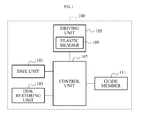
- FIG. 1 illustrates a configuration of a tactile feedback apparatus, according to example embodiments.
- a tactile feedback apparatus 100 may include a disk unit 101, a disk restoring unit 103, a driving unit 105 including an elastic member 109, and a control unit 107.
- the tactile feedback apparatus 100 may further include a guide member 111 to fix an angle or a height of the disk unit 101.
- the disk unit 101 may correspond to a portion touched by a finger of a user, and may be disposed on an upper side of the tactile feedback apparatus 100, for example, in a form of a plate.
- the disk unit 101 may transfer power, force or pressure sensed by for instance a remote sensor, to the finger of the user by adjusting a height, a direction of a gradient, or a level of a gradient, based on a height adjusted by the driving unit 105, for each radially symmetric point.
- a three degrees of freedom (3DOF) motion may be provided.
- the sensor may be arranged remotely in conjunction with for instance a robot or the power, force or pressure to be exerted on a user's finger may be determined in the sensor signal by a control of a virtual environment.
- remote control by the user over the robot can be achieved, for example to effect manipulations by the robot to perform any operation under direct but remote control of the user, who is provided with tactile feedback information from the robot to be able to effectively control the robot remotely.
- the sensor signal is synthesized in stead of measured, for example by a control of a virtual environment, the user is enabled to control objects or the like in the virtual environment, with improved tactile feedback, thus enhancing the impression that the user is in reality rather than the virtual environment.
- the disk unit 101 may form various patterns on a surface of the disk unit 101 in order to improve an effect of a tactile feedback to the finger touching the disk unit 101.
- the disk restoring unit 103 may correspond to, for example, a spring, and may be connected to the disk unit 101 and the upper side of the tactile feedback apparatus 100. That is, the disk restoring unit 103 may be disposed between the disk unit 101 and the driving unit 105 to maintain a gradient of the disk unit 101 formed according to the height at which the disk unit is supported, to remain within a predetermined range.
- the disk restoring unit 103 may adjust the gradient of the disk unit 101 to be the original gradient in accordance with a characteristic of the disk restoring unit 103, thereby restoring the gradient of the disk unit 101 to be in the original state.
- the disk restoring unit 103 may be formed to be thin with a metal plate or an elastic material, for example, rubber, and may be formed in various patterns.
- N driving units may be provided as the driving unit 105, and may be disposed below the disk unit 101 to support a lower portion of the disk unit 101.
- N may be a natural number.
- the N driving units may correspond to N pneumatic balloon driving units that may support the disk unit 101, using air pressure.
- each of the N pneumatic balloon driving units may adjust a height at which the disk unit 101 is supported at each of N radially symmetric points designated, based on the center of the disk unit 101, by supporting the disk unit 101 using each respective air pressure, corresponding to an amount of air provided, for each of the N radially symmetric points.
- the driving unit 105 may correspond to a motor driving unit to support the lower portion of the disk unit 101, using a drive shaft that moves in response to a pulse being applied. That is, the motor driving unit may adjust a height at which the disk unit 101 is supported, by moving the drive shaft upward and downward depending on a strength of a pulse applied.
- N motor driving units may be provided as the driving unit 105
- each of the N motor driving units may adjust a height at which the disk unit 101 is supported at each of the N radially symmetric points that are designated, based on the center of the disk unit, by moving the drive shaft depending on the strength of the pulse applied, for each of the N radially symmetric points.
- the motor driving unit may correspond to, for example, a magnetic driving device provided in a form of a solenoid.
- the motor driving unit may include a triangular stand to convert a horizontal direction of a push strength that is formed in response to the pulse being applied into a vertical direction, and to transfer, to the drive shaft, the push strength of which the direction is converted to the vertical direction. That is, when the motor driving unit moves the triangular stand in a rightward and a leftward direction, i.e., in a horizontal direction depending on the strength of the pulse applied, the drive shaft connected to the triangular stand may move in an upward and a downward direction, i.e., in a vertical direction, and may support the lower portion of the disk unit 101.
- the triangular stand may move the drive shaft in the upward and the downward direction by adjusting a portion in which an inclined plane comes into contacts with the drive shaft, depending on the applied push strength, thereby adjusting the height at which the disk unit 101 is supported.
- Each of the N driving motor driving units, including a triangular stand may adjust a height at which the disk unit 101 is supported at each of N radially symmetric points that are designated, based on the center of the disk unit 101, by moving the drive shaft depending on the applied push strength, for each of the N radially symmetric points.
- the control unit 107 may determine the height at which the disk unit 101 is supported, based on the signal generated by the sensor, using N driving units.
- the control unit 107 may determine the height at which the disk unit 101 is supported by controlling, based on the signal generated by the sensor, an amount of air that is provided to each of the N pneumatic balloon driving units.
- the control unit 107 may determine the height at which the disk unit 101 is supported, by controlling, based on the signal, a strength of a pulse that is applied to each of the N motor driving units.
- the control unit 107 may determine, directly or through the triangular stand, based on the signal generated by the sensor, the height at which the disk unit 101 is supported, by controlling the applied push strength to each of the N motor driving units. That is, the control unit 107 may adjust a gradient or a height of the disk unit 101 by adjusting the height at which the disk unit 101 is supported by the N driving units.
- the elastic member 109 may be included in the driving unit 105, and may be used as a buffer between the disk unit 101 and the driving unit 105.
- the elastic member 109 may control, according to a situation, an inflow of air into an air chamber included in the driving unit 105 or an outflow of air from the air chamber.
- the height at which the disk unit 101 is supported by the pneumatic balloon driving unit may be adjusted, by preventing the compressed air from flowing to the outside through a predetermined air vent. That is, the elastic member 109 may inflate depending on an amount of air that is provided by the pneumatic balloon driving unit, along with the air chamber disposed below the elastic member 109, thereby increasing the height at which the disk unit 101 is supported. In this instance, the elastic member 109 may restrict a maximum height at which the disk unit 101 is supported, by setting a permitted level of the inflation to be within a predetermined range.
- the elastic member 109 may open the air vent so that the air may flow out of the air chamber. In this instance, the elastic member 109 may restrain the disk unit 101 from being lowered below a predetermined height, along with the disk restoring unit 103.
- the guide member 111 may be disposed around the disk unit 101, and may include a concave portion in which the finger of the user may be placed comfortably when touching the disk unit 101. That is, the guide member 111 may induce a natural contact of the finger to the disk unit 101, by including portions in a curved form, which fit on other parts of the finger, excluding the part touching the disk unit 101.
- the guide member 111 may fix an angle or a height at which the finger of the user touches the disk unit 101, thereby restricting changes in the contact made to the disk unit 101, resulting from a movement of the finger. Accordingly, the guide member 111 may enable the user to sense a change in the disk unit 101 with a fixed part of the finger, for example, a fingertip, which is sensitive to a tactile sense.
- the tactile feedback apparatus 100 may adjust a height, a direction of gradient, or a level of gradient of the disk unit 101 by adjusting the height at which the disk unit 101 is supported, based on a signal generated by a sensor, thereby intuitively recognizing power sensed by the sensor, with the finger of the user touching the disk unit 101. Accordingly, the tactile feedback apparatus 100 may be applied to a robot, for example, a surgical robot, that controls a sensitive tissue, for example, a human body, or an object. The tactile feedback apparatus 100 may transfer, to the user, power used to touch a tissue by an end part of the robot, and may enable the user to control power used to control the robot, in a sophisticated manner, based on the transferred power, thereby improving efficiency and safety in tasks that use robots.
- FIG. 2 illustrates a perspective view of a disk unit 203 in a tactile feedback apparatus 200, according to example embodiments.
- a tactile feedback apparatus 200 may include a disk unit 203, for example, provided in a form of a circular plate, on an upper side of a body 201, including a driving unit.
- the disk unit 203 may be rotatable in directions x and y within a predetermined range, based on first central axes 205 and 207, respectively, and may be movable in a direction x of a second central axis 209 within a predetermined range, and thus, a 3DOF motion may be provided. Accordingly, the disk unit 203 may be controlled at various angles through the 3DOF motion, and may transfer with ease, to a finger touching the disk unit 203, power corresponding to a sensed signal.
- FIG. 3 illustrates a top view of a tactile feedback apparatus 200, according to example embodiments.
- a tactile feedback apparatus 200 may include three pneumatic balloon driving units 301-1, 301-2, and 301-3 that are disposed on a lower portion of a disk unit 203, for example, in a radially symmetric form.
- each of the three pneumatic balloon driving units 301-1, 301-2, and 301-3 may adjust a height at which the disk unit 203 is supported at each of three radially symmetric points P 1 , P 2 , and P 3 that are designated based on the center of the disk unit, by supporting the disk unit 203 using each respective air pressure corresponding to an amount of air provided, for each of the three radially symmetric points P 1 , P 2 , and P 3.
- Each of the three pneumatic balloon driving units 301-1, 301-2, and 301-3 may independently control the amount of air provided, and may separately adjust a level of pushing the disk unit 203 at each of the three radially symmetric points P 1 , P 2 , and P 3 , thereby adjusting a strength of power and a direction in which a finger touching the disk unit 203 is stimulated.
- the tactile feedback apparatus 200 may include a disk restoring unit 305 that is disposed between the disk unit 203 and an upper side 303 of a body.
- the disk restoring unit 305 may be connected between the disk unit 203 and the upper side 303 of the body, and may have a characteristic of restoring a gradient of the disk unit 203 to be in the original state.
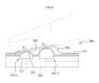
- FIG. 4 illustrates a cross-sectional view of the tactile feedback apparatus 200 of FIG. 3 .
- the tactile feedback apparatus 200 may include a disk unit 203, a disk restoring unit 305 to restore the inclined disk unit 203, and pneumatic balloon driving units 301-1 and 301-2 that support a lower portion of the disk unit 203.
- Each of the pneumatic balloon driving units 301-1 and 301-2 may include an air chamber 311, and an elastic member 307 that inflates in response to an inflow of air, and transfers power used to support the disk unit 203.
- the disk unit 203 may transfer power sensed by a sensor to a finger of a user touching the disk unit 203, by adjusting a height, a direction of a gradient, or a level of a gradient, based on a height adjusted by each of the pneumatic balloon driving units 301-1 and 301-2, for each of radially symmetric points p 1 and p 2 .
- the first pneumatic balloon driving unit 301-1 may adjust a height at which the disk unit 203 is supported at the first radially symmetric point p 1 , using air pressure corresponding to an amount of air provided to the first pneumatic balloon driving unit 301-1
- the second pneumatic balloon driving unit 301-2 may adjust a height at which the disk unit 203 is supported at the second radially symmetric point p 2 , to be different from the height at which the disk unit 203 is supported at the first radially symmetric point p 1 , using air pressure corresponding to an amount of air provided to the second pneumatic balloon driving unit 301-2. Accordingly, the disk unit 203 may be tilted at an angle corresponding to a signal generated by the sensor.
- the elastic member 307 When compressed air is provided to the air chamber 311 through an air tube 309 that is connected to the outside, the elastic member 307 may inflate to push the disk unit 203 in an upward direction. In this instance, the elastic member 307 may prevent the disk unit 203 from being positioned beyond a predetermined range of a direction or an angle, by controlling a level of inflation.
- the tactile feedback apparatus 200 may adjust the height at which the disk unit 203 is supported at the second radially symmetric point p 2 to be higher than the height at which the disk unit 203 is supported at the first radially symmetric point p 1 , by controlling the amount of air provided to the second pneumatic balloon driving unit 301-2 to be relatively greater than the amount of air provided to the first pneumatic balloon driving unit 301-1, thereby tilting the disk unit 203 to the left side.
- a gradient of the disk unit 203 may correspond to a level of difference between the heights at which the disk unit 203 is supported at the first and second radially symmetric points p 1 and p 2.
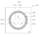
- FIG. 5 illustrates a top view of a tactile feedback apparatus 200, according to other example embodiments.
- a tactile feedback apparatus 200 may include three motor driving units 501-1, 501-2, and 501-3 that are disposed on a lower portion of a disk unit 203, for example, in a radially symmetric form.
- each of the three motor driving units 501-1, 501-2, and 501-3 may adjust a height at which the disk unit 203 is supported at each of three radially symmetric points p 1 , p 2 , and p 3 that are designated based on the center of the disk unit 203, by moving each of drive shafts 503-1, 503-2, and 503-3 depending on a strength of a pulse being applied, for each of the three radially symmetric points p 1 , p 2 , and p 3 .
- Each of the three motor driving units 501-1, 501-2, and 501-3 may independently control an amount of electric power provided, that is, the strength of the pulse provided, and may adjust a level of pushing the disk unit 203 at each of the three radially symmetric points p 1 , p 2 , and p 3 separately, thereby adjusting a strength of power and a direction in which a finger touching the disk unit 203 is stimulated.
- the tactile feedback apparatus 200 may include a disk restoring unit 305 that is disposed between the disk unit 203 and an upper side 303 of a body.
- the disk restoring unit 305 may be connected between the disk unit 203 and the upper side 303 of the body, and may have a characteristic of restoring a gradient of the disk unit 203 to be in the original state.
- FIG. 6 illustrates a cross-sectional view of the tactile feedback apparatus of FIG. 5 .
- the tactile feedback apparatus 200 may include a disk unit 203, a disk restoring unit 305 to restore the inclined disk unit 203, and motor driving units 501-1 and 501-2 that support a lower portion of the disk unit 203.
- the disk unit 203 may transfer power sensed by a sensor to a finger of a user touching the disk unit 203, by adjusting a height, a direction of gradient, or a level of gradient, based on a height adjusted by each of the motor driving units 501-1 and 501-2, for each of radially symmetric points p 1 and p 2.
- the first motor driving unit 501-1 may adjust a height at which the disk unit 203 is supported at the first radially symmetric point p 1 , by moving a drive shaft 503-1, depending on a strength of a pulse applied to the first motor driving unit 501-1
- the second motor driving unit 501-2 may adjust a height at which the disk unit 203 is supported at the second radially symmetric point p 2 , to be different from the height at which the disk unit 203 is supported at the first radially symmetric point p 1 , by moving a drive shaft 503-2 depending on a strength of a pulse applied to the second motor driving unit 501-2.
- the motor driving units 501-1 and 501-2 may adjust the heights at which the disk unit 203 is supported, by directly moving the drive shafts 503-1 and 503-2 in an upward and a downward direction, respectively.
- the tactile feedback apparatus 200 may adjust the height at which the disk unit 203 is supported at the second radially symmetric point p 2 to be higher than the height at which the disk unit 203 is supported at the first radially symmetric point p 1 , by controlling a level of moving the drive shaft 503-2 depending on the strength of the pulse applied to the second motor driving unit 501-2 to be greater than a level of moving the drive shaft 503-1, depending on the pulse applied to the first motor driving unit 501-1, thereby tilting the disk unit 203 to the left side.
- a gradient of the disk unit 203 may correspond to a level of difference between the heights at which the disk unit 203 is supported at the first and second radially symmetric points p 1 and p 2.
- FIG. 7 illustrates another cross-sectional view of the tactile feedback apparatus of FIG. 5 .
- the tactile feedback apparatus 200 may include motor driving units 501-1 and 501-2 as driving units, and a triangular stand 701-1 having an inclined plane 703-1, in the motor driving unit 501-1, and a triangular stand 701-2 having an inclined plane 703-2, in the motor driving unit 501-2.
- the triangular stands 701-1 and 701-2 may move the drive shafts 503-1 and 503-2, respectively, in an upward and a downward direction to support a disk unit 203, using power of a vertical direction, generated by the motor driving units 501-1 and 501-2. That is, each of the triangular stands 701-1 and 701-2 may convert, into a vertical direction, a horizontal direction of a push strength that is formed in response to a pulse applied to each of the motor driving units 501-1 and 501-2, and may transfer, to each of the drive shafts 503-1 and 503-2, the push strength of which the direction is converted to the vertical direction.
- the triangular stands 701-1 and 701-2 may have the inclined planes 703-1 and 703-2, respectively, on which the drive shafts 503-1 and 503-2 move along the slopes in an upward and a downward direction, according to a horizontal movement resulting from the push.
- the first triangular stand 701-1 may adjust the height at which the disk unit 203 is supported at the first radially symmetric point p 1 , using a vertical movement of the drive shaft 503-1, by moving the drive shaft 503-1 along the inclined plane 703-1 depending on a push strength of a horizontal direction formed by the first motor driving unit 501-1.
- the second triangular stand 701-2 may adjust, using a vertical movement of the drive shaft 503-2, the height at which the disk unit 203 is supported at the second radio symmetry point p 2 , to be different from the height at which the disk unit 203 is supported at the first radially symmetric point p 1 , by moving the drive shaft 503-2 along the inclined plane 703-2 depending on a push strength of a horizontal direction formed by the second motor driving unit 501-2.
- the tactile feedback apparatus 200 may adjust the height at which the disk unit 203 is supported at the second radially symmetric point p 2 to be higher than the height at which the disk unit 203 is supported at the first radially symmetric point p 1 , by controlling a level of moving the drive shaft 503-2 in an upward and a downward direction through the second triangular stand 701-2 to be relatively greater than a level of moving the drive shaft 503-1 in an upward and a downward direction through the first triangular stand 701-1, thereby tilting the disk unit 203 to the left side.
- a gradient of the disk unit 203 may correspond to a level of difference between the heights at which the disk unit 203 is supported at the first and second radially symmetric points p 1 and p 2.
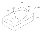
- FIG. 8 illustrates a perspective view of a tactile feedback apparatus, according to other example embodiments.
- a tactile feedback apparatus 200 may include a guide member 801 that is disposed on an upper portion of a body 201.
- the guide member 801 may be disposed around a disk unit 203, and may include a concave portion 803 in which a finger of a user may be placed comfortably when touching the disk unit 203.
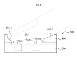
- FIG. 9 illustrates a cross-sectional view of the tactile feedback apparatus of FIG. 8 .
- the guide member 801 of the tactile feedback apparatus 200 may induce a natural contact of the finger to the disk unit 203, by including portions 803-1 and 803-2 in a curved form, which fit on other parts of the finger, excluding the part touching the disk unit 203.
- the tactile feedback apparatus 200 may fix an angle or a height at which the finger of the user touches the disk unit 203, using the guide member 801, thereby restricting changes in contact made to the disk unit 203, resulting from a movement of the finger. Accordingly, the tactile feedback apparatus 200 may enable the user to sense a change in the disk unit 203 with a fixed part of the finger, for example, a fingertip which is sensitive to a tactile sense.
- FIG. 10 illustrates a method of operating a tactile feedback apparatus, according to example embodiments.
- the tactile feedback apparatus may detect a finger of a user touching a disk unit.
- the disk unit for example, provided in a form of a plate, may adjust a height, a direction of a gradient, or a level of a gradient by adjusting a height at which the disk unit is supported by a driving unit, at each radially symmetric point, thereby transferring power sensed by a sensor to the finger of the user.
- the disk unit since the disk unit may be movable or rotatable in directions x, y, and z; and thus, a 3DOF motion may be provided.
- the tactile feedback apparatus may determine the height at which the disk unit is supported, based on a signal generated by the sensor.
- the tactile feedback apparatus may determine the height at which the disk unit is supported by controlling, based on the signal, an amount of air that is provided to each of N pneumatic balloon driving units.
- the tactile feedback apparatus may designate N radially symmetric points based on the center of the disk unit, and may adjust a height at which the disk unit is supported at each of the N radially symmetric points, using each respective air pressure corresponding to the amount of air provided, for each of the N radially symmetric points.
- the tactile feedback apparatus may determine the height at which the disk unit is supported by controlling, based on the signal, a strength of a pulse that is applied to each of N motor driving units.
- the tactile feedback apparatus may designate N radially symmetric points based on the center of the disk unit, and may adjust a height at which the disk unit is supported at each of the N radially symmetric points by moving a drive shaft, depending on the strength of the pulse applied, for each of the N radially symmetric points.
- the motor driving unit may include a triangular stand that converts a horizontal direction of a push strength that is formed in response to a pulse being applied into a vertical direction, and transfers, to the drive shaft, the push strength of which the direction is converted to the vertical direction. That is, the triangular stand may convert the horizontal direction of the power transferred from the motor driving unit into the vertical direction by moving the drive shaft along an inclined plane, and may transfer the power to the drive shaft, thereby determining the height at which the disk unit is supported by the drive shaft.
- the tactile feedback apparatus may include an elastic member.
- the tactile feedback apparatus may enable the elastic member to inflate depending on an amount of air that is provided by the pneumatic balloon driving unit, along with an air chamber disposed below the elastic member, thereby increasing the height at which the disk unit is supported.
- the tactile feedback apparatus may restrict a maximum height at which the disk unit is supported, by permitting a level of the inflation of the elastic member within a predetermined range.
- the tactile feedback apparatus may support the lower portion of the disk unit by controlling N driving units to be set at the determined height.
- the tactile feedback apparatus may fix an angle or a height at which the finger of the user touches the disk unit, using a guide member that is disposed around the disk unit.
- the tactile feedback apparatus may employ the guide member, which may include a concave portion in which the finger of the user may be placed comfortably when touching the disk unit. That is, the tactile feedback unit may induce a natural contact of the finger to the disk unit, using the guide member including portions in a curved form, which fit on other parts of the finger, excluding the part touching the disk unit.
- the tactile feedback apparatus may fix an angle or a height at which the finger of the user touches the disk unit, thereby restricting changes in contact made to the disk unit, resulting from a movement of the finger. Accordingly, the tactile feedback apparatus may enable the user to sense a change in the disk unit with a fixed part of the finger.
- the tactile feedback apparatus may adjust a height, a direction of a gradient, or a level of a gradient of the disk unit by adjusting the height at which the disk unit is supported, based on a signal generated by a sensor, and may recognize power sensed by the sensor intuitively, with the finger of the user touching the disk unit.
- the methods according to the above-described example embodiments may be recorded, stored, or fixed in one or more non-transitory computer-readable storage media that includes program instructions to be implemented by a computer to cause a processor to execute or perform the program instructions.
- the media may also include, alone or in combination with the program instructions, data files, data structures, and the like.
- the media and program instructions may be those specially designed and constructed, or they may be of the kind well-known and available to those having skill in the computer software arts.
- Examples of the computer-readable recording media include a magnetic recording apparatus, an optical disk, a magneto-optical disk, and/or a semiconductor memory (for example, RAM, ROM, etc.).
- Examples of the magnetic recording apparatus include a hard disk device (HDD), a flexible disk (FD), and a magnetic tape (MT).
- Examples of the optical disk include a DVD (Digital Versatile Disc), a DVD-RAM, a CD-ROM (Compact Disc - Read Only Memory), and a CD-R (Recordable)/RW.
- the tactile feedback apparatus 200 may include at least one processor to execute at least one of the above-described units and methods.
Applications Claiming Priority (1)
| Application Number | Priority Date | Filing Date | Title |
|---|---|---|---|
| KR1020110094501A KR101894951B1 (ko) | 2011-09-20 | 2011-09-20 | 촉각 전달 장치 및 촉각 전달 장치의 동작 방법 |
Publications (3)
| Publication Number | Publication Date |
|---|---|
| EP2573648A2 true EP2573648A2 (de) | 2013-03-27 |
| EP2573648A3 EP2573648A3 (de) | 2013-06-12 |
| EP2573648B1 EP2573648B1 (de) | 2020-04-08 |
Family
ID=46049246
Family Applications (1)
| Application Number | Title | Priority Date | Filing Date |
|---|---|---|---|
| EP12165746.4A Active EP2573648B1 (de) | 2011-09-20 | 2012-04-26 | Taktile Rückmeldungsvorrichtung, System und Verfahren zum Betrieb einer taktilen Rückmeldungsvorrichtung |
Country Status (5)
| Country | Link |
|---|---|
| US (1) | US9122308B2 (de) |
| EP (1) | EP2573648B1 (de) |
| JP (1) | JP5903001B2 (de) |
| KR (1) | KR101894951B1 (de) |
| CN (1) | CN103019371B (de) |
Families Citing this family (9)
| Publication number | Priority date | Publication date | Assignee | Title |
|---|---|---|---|---|
| JP6294170B2 (ja) * | 2014-06-26 | 2018-03-14 | 京セラ株式会社 | 触感呈示装置 |
| KR101848812B1 (ko) | 2014-07-18 | 2018-04-16 | 주식회사 씨케이머티리얼즈랩 | 촉각 정보 제공 장치 |
| US10353469B2 (en) | 2014-11-12 | 2019-07-16 | Kyocera Corporation | Tactile sensation providing device |
| CN105573490A (zh) * | 2015-11-12 | 2016-05-11 | 于明 | 一种人机交互系统、穿佩设备和方法 |
| US10568701B2 (en) * | 2016-12-19 | 2020-02-25 | Ethicon Llc | Robotic surgical system with virtual control panel for tool actuation |
| CN108762484B (zh) * | 2018-04-17 | 2020-12-08 | 西北工业大学 | 用于物理人机交互当中的现实触觉的气动模拟方法 |
| JP2020004314A (ja) * | 2018-07-02 | 2020-01-09 | 株式会社東海理化電機製作所 | スイッチ装置 |
| KR20200092665A (ko) * | 2019-01-25 | 2020-08-04 | 삼성전자주식회사 | 생체신호 측정용 텍스쳐 인터페이스 및 이를 포함한 생체신호 측정장치 |
| CN114469660B (zh) * | 2022-01-25 | 2023-12-15 | 池浩 | 方向指引装置、方向指引系统及方向指引方法 |
Citations (5)
| Publication number | Priority date | Publication date | Assignee | Title |
|---|---|---|---|---|
| EP1816545A2 (de) * | 2003-05-30 | 2007-08-08 | Immersion Corporation | System und Verfahren zur haptischen Rückkoppelung mit niedriger Leistung |
| WO2008054856A2 (en) * | 2006-04-14 | 2008-05-08 | The Regents Of The University California | Novel enhanced haptic feedback processes and products for robotic surgical prosthetics |
| US20080248836A1 (en) * | 2007-04-04 | 2008-10-09 | Motorola, Inc. | Method and apparatus for controlling a skin texture surface on a device using hydraulic control |
| US20100226075A1 (en) * | 2009-03-06 | 2010-09-09 | Sony Ericsson Mobile Communications Ab | Electroactive actuator for portable communication devices |
| WO2011075390A1 (en) * | 2009-12-18 | 2011-06-23 | Honda Motor Co., Ltd. | Morphable pad for tactile control |
Family Cites Families (23)
| Publication number | Priority date | Publication date | Assignee | Title |
|---|---|---|---|---|
| JPS60106287U (ja) * | 1983-12-22 | 1985-07-19 | 富士通テン株式会社 | カム機構を用いた蓋体の開閉機構 |
| JPS62150088U (de) * | 1986-03-13 | 1987-09-22 | ||
| JPH0639909Y2 (ja) * | 1988-06-13 | 1994-10-19 | 工業技術院長 | 触覚発生装置 |
| JP3075546B2 (ja) | 1992-05-11 | 2000-08-14 | 日本電信電話株式会社 | 触覚センサをもちいた6自由度ポインティング装置 |
| JPH06210581A (ja) * | 1993-01-20 | 1994-08-02 | Olympus Optical Co Ltd | 操作装置 |
| US5739811A (en) * | 1993-07-16 | 1998-04-14 | Immersion Human Interface Corporation | Method and apparatus for controlling human-computer interface systems providing force feedback |
| US5625576A (en) | 1993-10-01 | 1997-04-29 | Massachusetts Institute Of Technology | Force reflecting haptic interface |
| JPH0868379A (ja) * | 1994-08-29 | 1996-03-12 | Oriental Motor Co Ltd | リニアパルスモータを備えた往復形ポンプ |
| US6636197B1 (en) * | 1996-11-26 | 2003-10-21 | Immersion Corporation | Haptic feedback effects for control, knobs and other interface devices |
| JPH10249768A (ja) | 1997-03-12 | 1998-09-22 | Tokai Rubber Ind Ltd | 力センサー |
| US6233504B1 (en) * | 1998-04-16 | 2001-05-15 | California Institute Of Technology | Tool actuation and force feedback on robot-assisted microsurgery system |
| AU5652599A (en) * | 1998-09-22 | 2000-04-10 | Yasufumi Mase | Information processor for visually disabled person and tactile input/output device |
| US7196688B2 (en) | 2000-05-24 | 2007-03-27 | Immersion Corporation | Haptic devices using electroactive polymers |
| KR100923971B1 (ko) * | 2002-12-30 | 2009-10-29 | 삼성전자주식회사 | 스위치장치 |
| JP2004280360A (ja) * | 2003-03-14 | 2004-10-07 | Nippon Telegr & Teleph Corp <Ntt> | 指紋センサ装置および指紋認証装置 |
| JP4598721B2 (ja) * | 2006-05-22 | 2010-12-15 | シャープ株式会社 | 操作キー部品 |
| JP4997592B2 (ja) | 2007-03-30 | 2012-08-08 | インピュテクス株式会社 | 指装着型入力デバイスとプログラム |
| KR100950234B1 (ko) | 2007-07-06 | 2010-03-29 | 한국표준과학연구원 | 압력 센서를 이용한 마우스 알고리즘 구현 방법 |
| US8138895B2 (en) | 2007-10-19 | 2012-03-20 | Sony Corporation | Force/tactile feedback device |
| US8547339B2 (en) * | 2008-01-04 | 2013-10-01 | Tactus Technology, Inc. | System and methods for raised touch screens |
| JP5238626B2 (ja) | 2008-06-27 | 2013-07-17 | 学校法人東京工芸大学 | 感覚提示装置 |
| KR101006367B1 (ko) | 2009-04-10 | 2011-01-10 | 한국과학기술원 | 촉각정보 입출력 장치 및 이를 이용한 촉각정보 입출력 방법 |
| EP2244274B1 (de) * | 2009-04-20 | 2016-09-21 | Lg Electronics Inc. | Tragbares Endgerät |
-
2011
- 2011-09-20 KR KR1020110094501A patent/KR101894951B1/ko active IP Right Grant
-
2012
- 2012-04-26 EP EP12165746.4A patent/EP2573648B1/de active Active
- 2012-05-04 CN CN201210138011.7A patent/CN103019371B/zh active Active
- 2012-06-08 JP JP2012131002A patent/JP5903001B2/ja active Active
- 2012-08-16 US US13/587,573 patent/US9122308B2/en active Active
Patent Citations (5)
| Publication number | Priority date | Publication date | Assignee | Title |
|---|---|---|---|---|
| EP1816545A2 (de) * | 2003-05-30 | 2007-08-08 | Immersion Corporation | System und Verfahren zur haptischen Rückkoppelung mit niedriger Leistung |
| WO2008054856A2 (en) * | 2006-04-14 | 2008-05-08 | The Regents Of The University California | Novel enhanced haptic feedback processes and products for robotic surgical prosthetics |
| US20080248836A1 (en) * | 2007-04-04 | 2008-10-09 | Motorola, Inc. | Method and apparatus for controlling a skin texture surface on a device using hydraulic control |
| US20100226075A1 (en) * | 2009-03-06 | 2010-09-09 | Sony Ericsson Mobile Communications Ab | Electroactive actuator for portable communication devices |
| WO2011075390A1 (en) * | 2009-12-18 | 2011-06-23 | Honda Motor Co., Ltd. | Morphable pad for tactile control |
Also Published As
| Publication number | Publication date |
|---|---|
| US20130069863A1 (en) | 2013-03-21 |
| JP2013066995A (ja) | 2013-04-18 |
| US9122308B2 (en) | 2015-09-01 |
| EP2573648A3 (de) | 2013-06-12 |
| JP5903001B2 (ja) | 2016-04-13 |
| CN103019371A (zh) | 2013-04-03 |
| EP2573648B1 (de) | 2020-04-08 |
| CN103019371B (zh) | 2017-01-11 |
| KR101894951B1 (ko) | 2018-10-15 |
| KR20130030913A (ko) | 2013-03-28 |
Similar Documents
| Publication | Publication Date | Title |
|---|---|---|
| EP2573648B1 (de) | Taktile Rückmeldungsvorrichtung, System und Verfahren zum Betrieb einer taktilen Rückmeldungsvorrichtung | |
| US10564727B2 (en) | Systems and methods for a low profile haptic actuator | |
| JP6728386B2 (ja) | 人間コンピュータインタフェースシステム | |
| US9977500B2 (en) | Thresholds for determining feedback in computing devices | |
| JP6478535B2 (ja) | 触覚変換を行うためのシステム及び方法 | |
| US20140049483A1 (en) | Display device and method for controlling the same | |
| KR20170018850A (ko) | 디바이스 제어를 위한 자기 제어기 | |
| JP2015535190A (ja) | 機器を移動させるためのセンサ | |
| US11435832B2 (en) | Input device, control method, and non-transitory recording medium | |
| KR20210004968A (ko) | 인간-컴퓨터 인터페이스 시스템 | |
| JP2022518880A (ja) | ロボットがトラップ状態から脱出するように制御する方法、装置、ロボット | |
| US8976013B2 (en) | Contact type tactile feedback apparatus and operating method of contact type tactile feedback apparatus | |
| KR101741105B1 (ko) | 전동 휠체어 기반의 제어 시스템 및 방법 | |
| US20230356076A1 (en) | Haptics for touch-input hardware interfaces of a game controller | |
| KR102097043B1 (ko) | 차량 미러 제어 장치 및 방법 | |
| KR101500227B1 (ko) | 음파 터치 패드 | |
| KR20110009752A (ko) | 멀티미디어 파일 재생시 재생 구간 탐색 장치 및 방법 |
Legal Events
| Date | Code | Title | Description |
|---|---|---|---|
| PUAI | Public reference made under article 153(3) epc to a published international application that has entered the european phase |
Free format text: ORIGINAL CODE: 0009012 |
|
| AK | Designated contracting states |
Kind code of ref document: A2 Designated state(s): AL AT BE BG CH CY CZ DE DK EE ES FI FR GB GR HR HU IE IS IT LI LT LU LV MC MK MT NL NO PL PT RO RS SE SI SK SM TR |
|
| AX | Request for extension of the european patent |
Extension state: BA ME |
|
| PUAL | Search report despatched |
Free format text: ORIGINAL CODE: 0009013 |
|
| AK | Designated contracting states |
Kind code of ref document: A3 Designated state(s): AL AT BE BG CH CY CZ DE DK EE ES FI FR GB GR HR HU IE IS IT LI LT LU LV MC MK MT NL NO PL PT RO RS SE SI SK SM TR |
|
| AX | Request for extension of the european patent |
Extension state: BA ME |
|
| RIC1 | Information provided on ipc code assigned before grant |
Ipc: G06F 3/01 20060101AFI20130507BHEP |
|
| 17P | Request for examination filed |
Effective date: 20131211 |
|
| RBV | Designated contracting states (corrected) |
Designated state(s): AL AT BE BG CH CY CZ DE DK EE ES FI FR GB GR HR HU IE IS IT LI LT LU LV MC MK MT NL NO PL PT RO RS SE SI SK SM TR |
|
| 17Q | First examination report despatched |
Effective date: 20140402 |
|
| STAA | Information on the status of an ep patent application or granted ep patent |
Free format text: STATUS: EXAMINATION IS IN PROGRESS |
|
| GRAP | Despatch of communication of intention to grant a patent |
Free format text: ORIGINAL CODE: EPIDOSNIGR1 |
|
| STAA | Information on the status of an ep patent application or granted ep patent |
Free format text: STATUS: GRANT OF PATENT IS INTENDED |
|
| INTG | Intention to grant announced |
Effective date: 20200102 |
|
| GRAS | Grant fee paid |
Free format text: ORIGINAL CODE: EPIDOSNIGR3 |
|
| GRAA | (expected) grant |
Free format text: ORIGINAL CODE: 0009210 |
|
| STAA | Information on the status of an ep patent application or granted ep patent |
Free format text: STATUS: THE PATENT HAS BEEN GRANTED |
|
| AK | Designated contracting states |
Kind code of ref document: B1 Designated state(s): AL AT BE BG CH CY CZ DE DK EE ES FI FR GB GR HR HU IE IS IT LI LT LU LV MC MK MT NL NO PL PT RO RS SE SI SK SM TR |
|
| REG | Reference to a national code |
Ref country code: GB Ref legal event code: FG4D |
|
| REG | Reference to a national code |
Ref country code: AT Ref legal event code: REF Ref document number: 1255248 Country of ref document: AT Kind code of ref document: T Effective date: 20200415 Ref country code: CH Ref legal event code: EP |
|
| REG | Reference to a national code |
Ref country code: DE Ref legal event code: R096 Ref document number: 602012069052 Country of ref document: DE |
|
| REG | Reference to a national code |
Ref country code: IE Ref legal event code: FG4D |
|
| REG | Reference to a national code |
Ref country code: NL Ref legal event code: MP Effective date: 20200408 |
|
| REG | Reference to a national code |
Ref country code: LT Ref legal event code: MG4D |
|
| PG25 | Lapsed in a contracting state [announced via postgrant information from national office to epo] |
Ref country code: NO Free format text: LAPSE BECAUSE OF FAILURE TO SUBMIT A TRANSLATION OF THE DESCRIPTION OR TO PAY THE FEE WITHIN THE PRESCRIBED TIME-LIMIT Effective date: 20200708 Ref country code: GR Free format text: LAPSE BECAUSE OF FAILURE TO SUBMIT A TRANSLATION OF THE DESCRIPTION OR TO PAY THE FEE WITHIN THE PRESCRIBED TIME-LIMIT Effective date: 20200709 Ref country code: LT Free format text: LAPSE BECAUSE OF FAILURE TO SUBMIT A TRANSLATION OF THE DESCRIPTION OR TO PAY THE FEE WITHIN THE PRESCRIBED TIME-LIMIT Effective date: 20200408 Ref country code: NL Free format text: LAPSE BECAUSE OF FAILURE TO SUBMIT A TRANSLATION OF THE DESCRIPTION OR TO PAY THE FEE WITHIN THE PRESCRIBED TIME-LIMIT Effective date: 20200408 Ref country code: SE Free format text: LAPSE BECAUSE OF FAILURE TO SUBMIT A TRANSLATION OF THE DESCRIPTION OR TO PAY THE FEE WITHIN THE PRESCRIBED TIME-LIMIT Effective date: 20200408 Ref country code: FI Free format text: LAPSE BECAUSE OF FAILURE TO SUBMIT A TRANSLATION OF THE DESCRIPTION OR TO PAY THE FEE WITHIN THE PRESCRIBED TIME-LIMIT Effective date: 20200408 Ref country code: PT Free format text: LAPSE BECAUSE OF FAILURE TO SUBMIT A TRANSLATION OF THE DESCRIPTION OR TO PAY THE FEE WITHIN THE PRESCRIBED TIME-LIMIT Effective date: 20200817 Ref country code: IS Free format text: LAPSE BECAUSE OF FAILURE TO SUBMIT A TRANSLATION OF THE DESCRIPTION OR TO PAY THE FEE WITHIN THE PRESCRIBED TIME-LIMIT Effective date: 20200808 |
|
| REG | Reference to a national code |
Ref country code: AT Ref legal event code: MK05 Ref document number: 1255248 Country of ref document: AT Kind code of ref document: T Effective date: 20200408 |
|
| PG25 | Lapsed in a contracting state [announced via postgrant information from national office to epo] |
Ref country code: HR Free format text: LAPSE BECAUSE OF FAILURE TO SUBMIT A TRANSLATION OF THE DESCRIPTION OR TO PAY THE FEE WITHIN THE PRESCRIBED TIME-LIMIT Effective date: 20200408 Ref country code: RS Free format text: LAPSE BECAUSE OF FAILURE TO SUBMIT A TRANSLATION OF THE DESCRIPTION OR TO PAY THE FEE WITHIN THE PRESCRIBED TIME-LIMIT Effective date: 20200408 Ref country code: LV Free format text: LAPSE BECAUSE OF FAILURE TO SUBMIT A TRANSLATION OF THE DESCRIPTION OR TO PAY THE FEE WITHIN THE PRESCRIBED TIME-LIMIT Effective date: 20200408 Ref country code: BG Free format text: LAPSE BECAUSE OF FAILURE TO SUBMIT A TRANSLATION OF THE DESCRIPTION OR TO PAY THE FEE WITHIN THE PRESCRIBED TIME-LIMIT Effective date: 20200708 |
|
| REG | Reference to a national code |
Ref country code: CH Ref legal event code: PL |
|
| PG25 | Lapsed in a contracting state [announced via postgrant information from national office to epo] |
Ref country code: AL Free format text: LAPSE BECAUSE OF FAILURE TO SUBMIT A TRANSLATION OF THE DESCRIPTION OR TO PAY THE FEE WITHIN THE PRESCRIBED TIME-LIMIT Effective date: 20200408 |
|
| REG | Reference to a national code |
Ref country code: DE Ref legal event code: R097 Ref document number: 602012069052 Country of ref document: DE |
|
| PG25 | Lapsed in a contracting state [announced via postgrant information from national office to epo] |
Ref country code: MC Free format text: LAPSE BECAUSE OF FAILURE TO SUBMIT A TRANSLATION OF THE DESCRIPTION OR TO PAY THE FEE WITHIN THE PRESCRIBED TIME-LIMIT Effective date: 20200408 Ref country code: IT Free format text: LAPSE BECAUSE OF FAILURE TO SUBMIT A TRANSLATION OF THE DESCRIPTION OR TO PAY THE FEE WITHIN THE PRESCRIBED TIME-LIMIT Effective date: 20200408 Ref country code: LI Free format text: LAPSE BECAUSE OF NON-PAYMENT OF DUE FEES Effective date: 20200430 Ref country code: CZ Free format text: LAPSE BECAUSE OF FAILURE TO SUBMIT A TRANSLATION OF THE DESCRIPTION OR TO PAY THE FEE WITHIN THE PRESCRIBED TIME-LIMIT Effective date: 20200408 Ref country code: RO Free format text: LAPSE BECAUSE OF FAILURE TO SUBMIT A TRANSLATION OF THE DESCRIPTION OR TO PAY THE FEE WITHIN THE PRESCRIBED TIME-LIMIT Effective date: 20200408 Ref country code: CH Free format text: LAPSE BECAUSE OF NON-PAYMENT OF DUE FEES Effective date: 20200430 Ref country code: ES Free format text: LAPSE BECAUSE OF FAILURE TO SUBMIT A TRANSLATION OF THE DESCRIPTION OR TO PAY THE FEE WITHIN THE PRESCRIBED TIME-LIMIT Effective date: 20200408 Ref country code: SM Free format text: LAPSE BECAUSE OF FAILURE TO SUBMIT A TRANSLATION OF THE DESCRIPTION OR TO PAY THE FEE WITHIN THE PRESCRIBED TIME-LIMIT Effective date: 20200408 Ref country code: EE Free format text: LAPSE BECAUSE OF FAILURE TO SUBMIT A TRANSLATION OF THE DESCRIPTION OR TO PAY THE FEE WITHIN THE PRESCRIBED TIME-LIMIT Effective date: 20200408 Ref country code: LU Free format text: LAPSE BECAUSE OF NON-PAYMENT OF DUE FEES Effective date: 20200426 Ref country code: AT Free format text: LAPSE BECAUSE OF FAILURE TO SUBMIT A TRANSLATION OF THE DESCRIPTION OR TO PAY THE FEE WITHIN THE PRESCRIBED TIME-LIMIT Effective date: 20200408 Ref country code: DK Free format text: LAPSE BECAUSE OF FAILURE TO SUBMIT A TRANSLATION OF THE DESCRIPTION OR TO PAY THE FEE WITHIN THE PRESCRIBED TIME-LIMIT Effective date: 20200408 |
|
| REG | Reference to a national code |
Ref country code: BE Ref legal event code: MM Effective date: 20200430 |
|
| PLBE | No opposition filed within time limit |
Free format text: ORIGINAL CODE: 0009261 |
|
| STAA | Information on the status of an ep patent application or granted ep patent |
Free format text: STATUS: NO OPPOSITION FILED WITHIN TIME LIMIT |
|
| PG25 | Lapsed in a contracting state [announced via postgrant information from national office to epo] |
Ref country code: PL Free format text: LAPSE BECAUSE OF FAILURE TO SUBMIT A TRANSLATION OF THE DESCRIPTION OR TO PAY THE FEE WITHIN THE PRESCRIBED TIME-LIMIT Effective date: 20200408 Ref country code: SK Free format text: LAPSE BECAUSE OF FAILURE TO SUBMIT A TRANSLATION OF THE DESCRIPTION OR TO PAY THE FEE WITHIN THE PRESCRIBED TIME-LIMIT Effective date: 20200408 Ref country code: BE Free format text: LAPSE BECAUSE OF NON-PAYMENT OF DUE FEES Effective date: 20200430 |
|
| 26N | No opposition filed |
Effective date: 20210112 |
|
| PG25 | Lapsed in a contracting state [announced via postgrant information from national office to epo] |
Ref country code: IE Free format text: LAPSE BECAUSE OF NON-PAYMENT OF DUE FEES Effective date: 20200426 |
|
| PG25 | Lapsed in a contracting state [announced via postgrant information from national office to epo] |
Ref country code: SI Free format text: LAPSE BECAUSE OF FAILURE TO SUBMIT A TRANSLATION OF THE DESCRIPTION OR TO PAY THE FEE WITHIN THE PRESCRIBED TIME-LIMIT Effective date: 20200408 |
|
| PG25 | Lapsed in a contracting state [announced via postgrant information from national office to epo] |
Ref country code: TR Free format text: LAPSE BECAUSE OF FAILURE TO SUBMIT A TRANSLATION OF THE DESCRIPTION OR TO PAY THE FEE WITHIN THE PRESCRIBED TIME-LIMIT Effective date: 20200408 Ref country code: MT Free format text: LAPSE BECAUSE OF FAILURE TO SUBMIT A TRANSLATION OF THE DESCRIPTION OR TO PAY THE FEE WITHIN THE PRESCRIBED TIME-LIMIT Effective date: 20200408 Ref country code: CY Free format text: LAPSE BECAUSE OF FAILURE TO SUBMIT A TRANSLATION OF THE DESCRIPTION OR TO PAY THE FEE WITHIN THE PRESCRIBED TIME-LIMIT Effective date: 20200408 |
|
| PG25 | Lapsed in a contracting state [announced via postgrant information from national office to epo] |
Ref country code: MK Free format text: LAPSE BECAUSE OF FAILURE TO SUBMIT A TRANSLATION OF THE DESCRIPTION OR TO PAY THE FEE WITHIN THE PRESCRIBED TIME-LIMIT Effective date: 20200408 |
|
| PGFP | Annual fee paid to national office [announced via postgrant information from national office to epo] |
Ref country code: FR Payment date: 20230321 Year of fee payment: 12 |
|
| PGFP | Annual fee paid to national office [announced via postgrant information from national office to epo] |
Ref country code: GB Payment date: 20230320 Year of fee payment: 12 |
|
| P01 | Opt-out of the competence of the unified patent court (upc) registered |
Effective date: 20230530 |
|
| PGFP | Annual fee paid to national office [announced via postgrant information from national office to epo] |
Ref country code: DE Payment date: 20230320 Year of fee payment: 12 |