EP2623996A1 - Voltage measuring circuit and method for monitoring the functionality of a voltage measuring circuit - Google Patents
Voltage measuring circuit and method for monitoring the functionality of a voltage measuring circuit Download PDFInfo
- Publication number
- EP2623996A1 EP2623996A1 EP12153689.0A EP12153689A EP2623996A1 EP 2623996 A1 EP2623996 A1 EP 2623996A1 EP 12153689 A EP12153689 A EP 12153689A EP 2623996 A1 EP2623996 A1 EP 2623996A1
- Authority
- EP
- European Patent Office
- Prior art keywords
- analog
- measuring circuit
- digital converter
- current
- current measuring
- Prior art date
- Legal status (The legal status is an assumption and is not a legal conclusion. Google has not performed a legal analysis and makes no representation as to the accuracy of the status listed.)
- Granted
Links
Images


Classifications
-
- G—PHYSICS
- G01—MEASURING; TESTING
- G01R—MEASURING ELECTRIC VARIABLES; MEASURING MAGNETIC VARIABLES
- G01R35/00—Testing or calibrating of apparatus covered by the other groups of this subclass
-
- G—PHYSICS
- G01—MEASURING; TESTING
- G01R—MEASURING ELECTRIC VARIABLES; MEASURING MAGNETIC VARIABLES
- G01R1/00—Details of instruments or arrangements of the types included in groups G01R5/00 - G01R13/00 and G01R31/00
- G01R1/20—Modifications of basic electric elements for use in electric measuring instruments; Structural combinations of such elements with such instruments
- G01R1/203—Resistors used for electric measuring, e.g. decade resistors standards, resistors for comparators, series resistors, shunts
-
- G—PHYSICS
- G01—MEASURING; TESTING
- G01R—MEASURING ELECTRIC VARIABLES; MEASURING MAGNETIC VARIABLES
- G01R19/00—Arrangements for measuring currents or voltages or for indicating presence or sign thereof
- G01R19/25—Arrangements for measuring currents or voltages or for indicating presence or sign thereof using digital measurement techniques
Definitions
- the invention relates to a current measuring circuit
- a sensor module for measuring an electrical current flowing through a conductor by measuring an input voltage between a first and a second input line of the sensor assembly and a sensor control for controlling the sensor assembly
- the sensor assembly comprises a first sensor device for detecting the strength of the electrical current by means of a first analog-to-digital converter for converting analog measured values into digitized measured values
- the current measuring circuit comprises an influencing device for variably connecting a test voltage or a test current to an input of the first analog-digital converter.
- the variable-contact influencing device may be a switch (for example, a relay or an electronic analog switch) with which an electrical connection from a voltage or current source to the input of the first analog-to-digital converter can be made and interrupted.
- the influencing device may comprise a voltage or current source which provides a voltage whose magnitude varies in a predetermined manner (transient or stationary) or which provides a current whose magnitude is predetermined in time (transient or stationary) changed.
- the invention relates to a method for monitoring a functionality of a current measuring circuit.
- Out DE 10 2005 055 272 B4 is a measuring device for detecting voltage measurements on a conductor section known, which may be an integral part of a motor vehicle.
- the measuring device comprises an analog-to-digital converter and the conductor section is arranged as close as possible to a battery terminal.
- the known measuring device is provided for measuring the size of leakage currents.
- a measuring current of known intensity is impressed from a switchable current source into the conductor section and the resistance value of the conductor section is determined via the voltage drop occurring thereby at the conductor section. It is assumed here that the ignition lock is switched off during the resistance measurement and thus possibly unknown consumers with a small leakage current cause a voltage drop in the conductor section, which is negligible compared to the measuring current.
- the present invention is intended to provide a current measuring circuit whose functionality can be checked during regular operation of a vehicle electrical system. Apart from the fact that the known measuring device does not have the purpose to solve this task, it would not be suitable for the following reason.
- the conductor section is both part of the load circuit and part of the test circuit. Thus flows through him the sum of the currents of the two circuits (1. Kirchoffoff law). In regular operation, the voltage drop caused by the load current at the conductor portion outweighs the voltage drop caused by the test current at the conductor portion. Compared to the load current, a test current still practicable strength would not have sufficient strength to cause a still reliably evaluable contribution to the voltage drop at the conductor section.
- the input of the first analog-to-digital converter is connected to the first input line of the sensor assembly via a first ballast impedance.
- the first ballast impedance between the first input line of the sensor assembly and the input of the first analog-to-digital converter does not change the fact that a test current still practicable strength would not have sufficient strength to cause a reliable evaluable influence on the voltage drop at the conductor section.
- it is possible with the current measuring circuit according to the invention to influence the input voltage of the first analog-to-digital converter by means of the test voltage or the test current targeted.
- the sensor control can make conclusions on the functionality of the current measuring circuit based on influencing-dependent measured values.
- the targeted influence allows the sensor control a correlation between the targeted influence and recorded measured values. Based on the correlation, the sensor controller can filter out information portions from the measurement results, which represent a system response of the current measuring circuit to the targeted influencing of the input of the first analog-to-digital converter.
- a direct voltage or direct current source can be used as the test voltage source or as the test current source.
- the ballast impedance may be a pure effective resistance (ie, a dummy resistance without reactance).
- an AC voltage source or an AC source can be used for the targeted influencing, the time course and / or frequency distribution is predetermined (preferably stationary).
- the AC or AC source may provide a periodic triangular voltage.
- the sensor control can filter out those AC components from the measurement signal to which the AC or AC source at the input of the analog-to-digital converter contributed.
- the targeted influence contains frequency components in a frequency range that does not contain the current to be measured on the conductor or that can not be measured in the conductor of the current measuring circuit according to specification.
- the first ballast impedance may comprise a filter (preferably a frequency filter, more preferably a bandpass filter or a lowpass filter). In the reverse direction, the filter can suppress indirect disturbances of the self-test function of the current measuring circuit by AC components which are above a cutoff frequency at which current through the conductor is to be detected by the current measuring circuit.
- the current measuring circuit may include a test reference input for connecting a test current source for providing the test current or for connecting a test voltage source for providing the test voltage, in particular wherein a reference potential terminal of the test voltage source is electrically connected to a reference potential terminal of the first analog-to-digital converter.
- the current measuring circuit may comprise a control connection, by means of which the variable connection of the test voltage or the test current is controllable by the sensor control.
- the targeted influenceability of the variable connection of the test voltage or the test current by the sensor control allows the sensor control a temporal correlation between a change in the connection and observed measurement results. Based on the temporal correlation, the sensor controller can filter out information pieces from the measurement results, which represent a system response of the current measuring circuit to the change in the connection.
- a change in the application of the test voltage or the test current may be made by the control circuit sending an operating parameter to the test voltage source or test current source, which it then has to apply.
- the sensor module may comprise a first sensor device for detecting the input voltage and a second sensor device for detecting the input voltage, wherein both sensor devices have a common measuring range.
- the sensor control can be prepared to bring about a defined operating state at an input of the first analog-to-digital converter and to evaluate the functionality of the current measuring circuit by means of a comparison of the digital measured values in the defined operating state with predetermined desired measurement results.
- the evaluation of the operability of the current measuring circuit can be simplified. The evaluation can be carried out faster and / or more often and / or with higher reliability.
- the sensor control can be prepared to carry out the assessment of the functionality of the current measuring circuit also taking into account digital measured values that can be detected by the second sensor device. If measured values output from the two sensor devices do not match sufficiently, the sensor controller may conclude that at least one of the two measurement channels is defective. Based on the consideration that typically both measurement channels will not fail at the same time, the sensor controller may be prepared to conclude by including additional information which of the two measurement channels is likely to be defective. The additional information may be obtained, for example, by means of the selective application of test voltages or test currents as described above to inputs of the first and / or second analog-to-digital converter. It depends on the application, whether it is better in case of failure, to perform an emergency operation with a presumably still functional single measuring channel or whether a complete abandonment of current readings is less consequential.
- the control connection can be guided at least in sections via a data bus, via which digitized measured values from the first analog-digital converter to the sensor control can be transmitted.
- the sensor assembly may include an adaptation unit for conditioning the digital measurements provided by the first analog-to-digital converter for transmission over the data bus.
- an adaptation unit for conditioning the digital measurements provided by the first analog-to-digital converter for transmission over the data bus.
- the adaptation unit may comprise the sensor control.
- the sensor assembly may include an adaptation unit for conditioning the digital measurements provided by the second analog-to-digital converter for transmission over the data bus.
- an adaptation unit for conditioning the digital measurements provided by the second analog-to-digital converter for transmission over the data bus.
- the adaptation unit may comprise a controller that can be used for a temporally alternating preparation of the digital measured values provided by the first analog-digital converter and the digital measured values provided by the second analog-digital converter.
- a controller for processing the digital measured values provided by the second analog-to-digital converter can be saved.
- the first analog-to-digital converter may be part of a microcontroller of the sensor assembly.
- the realization of the analog-to-digital converter function by means of a microcontroller can improve an adaptability to new requirements and an incorporation of further functionalities.
- the known method for monitoring the functionality of a current measuring circuit comprises the following steps: providing a current measuring circuit which comprises a first analog-to-digital converter for converting analog measured values into digitized measured values, wherein an input of the first analogue Digital converter is connected to a first input line of the current measuring circuit via a first ballast impedance; Influencing the input of the first analog-to-digital converter by applying a test voltage or a test current to the input of the first analog-to-digital converter; Capturing a reading during influencing the input of the first analog-to-digital converter; and evaluating a functionality of the current measuring circuit by means of a comparison of the detected measured value with predetermined desired measurement results.
- the input of the first analog-to-digital converter is connected to a first input line of the current measuring circuit via a first Vorschaltimpedanz
- the input voltage of the first analog-to-digital converter by means of the test voltage or the test current can be selectively influenced.
- the functionality of the current measuring circuit can be evaluated on the basis of influencing-dependent measured values.
- the targeted influence allows a correlation between the targeted influencing and the recorded measured values.
- On the basis of the correlation information shares can be filtered out of the measurement results, which represent a system response of the current measuring circuit on the targeted influencing the input of the first analog-to-digital converter.
- a vehicle in particular motor vehicle, comprises a power source 12 (for example, a battery, in particular a rechargeable battery and / or a vehicle battery), a sensor assembly 14, a power supply disconnecting device 16, a sensor controller 18, and an electrical load 20.
- the electrical load 20 may include a plurality of consumers of electrical energy (eg, starters, engine electronics, lighting, and assistance systems).
- the power supply isolator 16 is double-poleed into the circuit between the power source 12 and the electrical load 20.
- the sensor assembly 14 is disposed in the positive lead 22 between the positive terminal 24 of the current source 12 and the positive terminal 26 of the power supply separator 16.
- the sensor assembly 14 may be disposed in the negative lead 30 between the negative terminal 32 of the current source 12 and the negative terminal 34 of the power supply disconnecting device 16.
- the sensor controller 18 (for example, in a power controller or in a battery controller) is connected to the power source 12, the sensor assembly 14, and the power supply disconnect 16 via a data bus 36 (eg, via a CAN bus).
- the sensor controller 18 can receive measurement data from the current source 12 and the sensor assembly 14 via the data bus 36.
- the sensor controller 18 receives over the data bus 36, for example, current temperature readings from the current source 12 and current current measurements from the sensor assembly 14. In response to these and / or other data, the sensor controller 18 decides whether to command the power supply disconnect 16 via the data bus 36, the circuit between the power source 12 and the electrical load 20 to open or close.
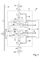
- the Fig. 2 shows a first embodiment of a current measuring circuit 38, which comprises a sensor assembly 14 and a control circuit 18.
- the control circuit 18 comprises two sensor devices 51, 52, each of which evaluates a voltage drop U 1 caused by a current I m flowing through a shunt RS.
- the first sensor device 51 comprises a first analog-digital converter 41
- the second sensor device 52 comprises a second analog-digital converter 42.
- An adaptation unit 90 is provided for processing the digital measured values U 1D , U 2D output by the analog-digital converters 41, 42 for transmitting the digital measured values U 1D , U 2D via a data bus 36 to the sensor controller 18.
- the adaptation unit 90 can comprise a separate adaptation unit, for example one controller each, for each of the two analog-to-digital converters 41, 42. However, it may also be advantageous to use a common controller for both adaptation units.
- the controller may be prepared for the application of a time division method in which a processor performance of the common controller alternately for adapting the digital measured values U 1D of the first analog-to-digital converter 41 and for adapting the digital measured values U 2D of the second analog-digital converter 42 is being used. Symbolize bold arrows in the figure Connections for data flows.
- the input 55a, 56 of the first analog-to-digital converter 41 (or the input 255a, 56 of the second analog-to-digital converter 42) is a voltage measuring input, in normal operation (in the non-short circuit case) only one input current flows with a very low current value Ue1 / Re1 (or Ue2 / Re2) through the ballast impedance Z1 (or Z2).
- the ballast impedance Z1 prevents the short circuit of the input 55a, 56 of the analog-to-digital converter 41 (or in the case of a short circuit of the input 255a, 56 of the analog-to-digital converter 42) other of the two analog-to-digital converters 41, 42 can no longer measure any voltage drop U 1 at the shunt RS.
- the ballast impedance Z1 and / or the ballast impedance Z2 may be a pure effective resistance (ie an impedance without reactance).
- the ballast impedances Z1 can fulfill the task of limiting the short-circuit current through the sensor device 51 (or 52) in the event of a short circuit.
- the real part of the impedance of the ballast impedance Z1 (or Z2) should be greater than the resistance value of the shunt RS by at least a factor of 10, particularly preferably at least by a factor of 30 or 50.
- the amount of the ballast impedance Z1 (or Z2) should be smaller than the input resistance Re1, Re2 of the respective analog-to-digital converter 41, 42 by at least a factor of 10, particularly preferably at least by a factor of 30 or 50.
- the prerequisite for U 1 to be determined with sufficient accuracy is that both the amount of the ballast impedance Z 1 (or Z 2) and the resistance value of the input resistance Re 1 (or Re 2) are known with sufficient accuracy.
- the current measuring circuit 38 comprises a test reference input 94 for applying a predefined test voltage potential U T from a test voltage source not shown in the figure and / or for impressing a predefined test current I T from a test current source 95.
- the current measuring circuit 38 comprises a second test reference input 294 for applying a predefined test voltage potential U T2 from a second test voltage source, not shown in the figure, and / or for impressing a predefined test current I T2 from a second test current source 295.
- the test voltage potential U T (or U T2 ) can each be a constant voltage potential or an AC potential. Accordingly, the test current I T (or I T2 ) may each be a constant current or an alternating current.
- the entrance 55a of the first analog-to-digital converter 41 of the first sensor device 51 is connected via a series circuit of a Aufschaltimpedanz Z T and a first switch S1 connected to the test reference input 94th
- line 56 provides the reference potential for the voltage U T.
- test current source 95 simplifies the self-test of the current sense circuit 38 in that, when using a test current source 95, the value of the turn-on impedance Z T need not be known accurately. From equation 3 or 4 it can be seen that the back-calculated voltage U 1 depends on the test voltage U T or on the test current I T when the first switch S1 is switched to current passage.
- the Aufschaltimpedanz Z T may be a pure effective resistance (ie, a dummy resistance without reactance).
- a control connection 96 is provided, by means of which the sensor controller 18 can actuate the first switch S1.
- the sensor controller 18 at the input 55a of the first analog-to-digital converter 41 bring about a defined operating state II and by means of a comparison of the measurement results in operating state II with predetermined measurement results on the functioning of the sensor devices 51, 52 infer.
- the operating state I denotes an operating state without test connection.
- the sensor controller 18 can filter information portions out of the measurement results U 1D , which represent a system response of the current measuring circuit 38 to the targeted influencing of the input 55a of the first analog-to-digital converter 41.
- a direct voltage or direct current source can be used as the test voltage or test current source 95.
- an AC voltage source or AC source whose temporal voltage or current profile and / or frequency spectrum is predetermined (preferably stationary) can be used as a test voltage or test current source 95 for targeted influencing.
- the AC or AC source may provide a (preferably zero-point) periodic voltage U T or a (preferably zero-point) periodic current I T.
- the voltage UT may be, for example, a triangular voltage or a sine voltage; and the current IT may be, for example, a current whose amplitude is sinusoidal or triangular in time.
- the sensor controller 18 can filter out those alternating voltage components from the measuring signal U 1D , to which the test voltage or test current source 95 contributed at the input 55a of the first analog-digital converter 41.
- the targeted influencing (by the test voltage or test current source 95) preferably contains frequency components in a frequency range which the current I m to be measured on the conductor 22 does not contain or should not be measured by the current measuring circuit 38 as specified.
- the first ballast impedance Z1 may comprise a filter (preferably a frequency filter, particularly preferably a bandpass filter or a lowpass filter).
- the current measuring function of the current measuring circuit 38 can be decoupled from the self-test function of the current measuring circuit 38 in that the self-test is carried out only in operating states of the vehicle electronics in which the function of the vehicle electronics is not affected.
- a development provides that the evaluation of the functionality of the current measuring circuit 38 can also be carried out taking into account measured values U 2D , which can be detected by the second sensor device 52.
- measured values U 2D can be detected by the second sensor device 52.
- the sensor controller 18 can conclude that at least one of the two measuring channels is defective. Based on the consideration that typically both measurement channels will not fail at the same time, the sensor controller 18 may be prepared to conclude by including additional information as to which of the two measurement channels is likely to be defective.
- the additional information can be obtained, for example, by means of the above-described selective connection of test voltages U T , U T2 or test currents I T , I T2 to inputs of the first 41 and / or second 42 analog-to-digital converter. It depends on the application whether it is better in the event of a fault to carry out an emergency operation only with a single presumably still functioning measuring channel or whether a complete omission of measured values U 1D , U 2D for the current I m to be measured is less consequential.
- the current measuring circuit 38 comprises a second test reference input 294
- the input 255a of the second analog-to-digital converter 42 of the second sensor device 52 is connected to the test reference input 294 via a series connection of a connection impedance Z T2 and a second switch S2.
- a control connection 296 is then provided, by means of which the sensor controller 18 can actuate the second switch S2.
- the sensor control 18 can also bring about a defined operating state II at the input 255a of the second analog-to-digital converter 41 and can conclude the functionality of the sensor devices 51, 52 by means of a comparison of the measurement results in operating state II with predetermined measurement results.
- the sensor controller 18 can filter out information portions from the measurement results U 2D , which represent a system response of the current measuring circuit 38 to the targeted influencing of the input 255a of the second analog-to-digital converter 42.
- the Aufschaltimpedanz Z T2 may be a pure effective resistance (ie, an impedance without reactance).
- a direct voltage or direct current source can be used as the test voltage or test current source 95.
- an AC voltage source or AC source whose temporal voltage or current profile and / or frequency spectrum is predetermined (preferably stationary) can be used as a test voltage or test current source 95 for targeted influencing.
- the AC or AC source may provide a (preferably zero-point) periodic voltage U T or a (preferably zero-point) periodic current I T.
- the voltage UT may be, for example, a triangular voltage or a sine voltage; and the stream IT may be, for example, a stream whose amplitude is sinusoidal or triangular in time.
- the sensor controller 18 can filter out those alternating voltage components from the measuring signal U 1D , to which the test voltage or test current source 95 contributed at the input 55a of the first analog-digital converter 41.
- the targeted influencing (by the test voltage or test current source 95) preferably includes frequency components in a frequency range which the current I m to be measured on the conductor 22 does not contain or should not be measured by the current measuring circuit 38 as specified.
- the first ballast impedance Z1 may comprise a filter (preferably a frequency filter, particularly preferably a bandpass filter or a lowpass filter).
- the current measuring function of the current measuring circuit 38 can be decoupled from the self-test function of the current measuring circuit 38 in that the self-test is carried out only in operating states of the vehicle electronics in which the function of the vehicle electronics is not affected.
- a development provides that the evaluation of the functionality of the current measuring circuit 38 can also be carried out taking into account measured values U 2D , which can be detected by the second sensor device 52.
- Use of the optional second test reference input 294 may help to improve availability of the current sense circuit 38 monitoring in the event that a function of the first test reference input 94 fails. Independently of this, use of the optional second test reference input 294 can contribute to increasing the reliability and / or validity of the monitoring of the functionality of the current measuring circuit 38.
- By means of the optional second test reference input 294 may (cross talk) to be tested from the voltage measuring input 255a of the second analog-to-digital converter 42 to the voltage measuring input 55a of the first analog-to-digital converter 41 and recognized, for example crosstalk.
- the illustrated method 100 for monitoring a functionality of a current measuring circuit 38 comprises the following steps 110, 120, 130, 140.
- a current measuring circuit 38 is provided which comprises a first analog-to-digital converter 41 for converting analog measured values into digitized measured values U 1D includes.
- an input 55a of the first analog-to-digital converter 41 is connected to a first input line 55 of the current measuring circuit 14 via a first ballast impedance Z1.
- an input 55a of the first analog-to-digital converter 41 is switched on a test voltage U T or a test current I T to the input 55 a of the first analog-to-digital converter 41.
- a digital measured value U 1D is detected while influencing the input 55a of the first analog-to-digital converter 41.
- a functionality of the current measuring circuit 38 is evaluated by means of a comparison of the detected digital measured value U 1D with predetermined desired measuring results.
- Analog and / or digital electrical signals which are represented in the exemplary embodiments in the form of voltages, can alternatively or additionally also be represented as (impressed) currents.
- voltages or currents mentioned in the description can be rescaled en route from their respective source to their respective sink.
- Analog or digital signals which are represented in the form of voltages or currents, can be linearly or nonlinearly coded according to a known method or according to a method not yet known today. Examples of applicable coding methods are pulse width modulation and pulse code modulation.
- the analog and / or digital signals can be transmitted electrically, optically or by radio.
- the analog and / or digital signals can be transmitted in space division (ie by means of different lines), in time division multiplex or in code division. The transmission of the analog and digital signals can take place via one or more bus systems.
Abstract
Description
Die Erfindung betrifft eine Strommessschaltung, die eine Sensorbaugruppe zur Messung eines durch einen Leiter fließenden elektrischen Stroms mittels Messung einer Eingangsspannung zwischen einer ersten und einer zweiten Eingangsleitung der Sensorbaugruppe und eine Sensorsteuerung zur Steuerung der Sensorbaugruppe umfasst, wobei die Sensorbaugruppe eine erste Sensorvorrichtung zur Erfassung der Stärke des elektrischen Stroms mittels eines ersten Analog-Digital-Wandlers zur Wandlung von analogen Messwerten in digitalisierte Messwerte umfasst und die Strommessschaltung eine Beeinflussungsvorrichtung zur veränderlichen Aufschaltung einer Testspannung oder eines Teststroms auf einen Eingang des ersten Analog-Digital-Wandlers umfasst. Die Beeinflussungsvorrichtung zur veränderlichen Aufschaltung kann ein Schalter (beispielsweise ein Relais oder ein elektronischer Analogschalter) sein, mit dem eine elektrische Verbindung von einer Spannungs- oder Stromquelle zu dem Eingang des ersten Analog-Digital-Wandlers herstellbar und unterbrechbar ist. Statt des Schalters kann die Beeinflussungsvorrichtung eine Spannungs- oder Stromquelle umfassen, die eine Spannung bereitstellt, deren Höhe sich in vorbestimmter Weise (transient oder stationär) zeitlich verändert, oder die einen Strom bereitstellt, dessen Höhe sich in vorbestimmter Weise (transient oder stationär) zeitlich verändert.The invention relates to a current measuring circuit comprising a sensor module for measuring an electrical current flowing through a conductor by measuring an input voltage between a first and a second input line of the sensor assembly and a sensor control for controlling the sensor assembly, wherein the sensor assembly comprises a first sensor device for detecting the strength of the electrical current by means of a first analog-to-digital converter for converting analog measured values into digitized measured values, and the current measuring circuit comprises an influencing device for variably connecting a test voltage or a test current to an input of the first analog-digital converter. The variable-contact influencing device may be a switch (for example, a relay or an electronic analog switch) with which an electrical connection from a voltage or current source to the input of the first analog-to-digital converter can be made and interrupted. Instead of the switch, the influencing device may comprise a voltage or current source which provides a voltage whose magnitude varies in a predetermined manner (transient or stationary) or which provides a current whose magnitude is predetermined in time (transient or stationary) changed.
Außerdem betrifft die Erfindung ein Verfahren zur Überwachung einer Funktionsfähigkeit einer Strommessschaltung.Moreover, the invention relates to a method for monitoring a functionality of a current measuring circuit.
Aus
Mit der vorliegenden Erfindung soll eine Strommessschaltung bereitgestellt werden, deren Funktionsfähigkeit während eines regulären Betriebs eines Bordnetzes überprüft werden kann. Abgesehen davon, dass die bekannte Messvorrichtung nicht den Zweck hat, diese Aufgabe zu lösen, wäre sie aus folgendem Grund auch nicht dafür geeignet. Der Leiterabschnitt ist sowohl Teil des Verbraucherstromkreises als auch Teil des Teststromkreises. Damit fließt durch ihn die Summe der Ströme der beiden Stromkreise (1. Kirchhoffsches Gesetz). Im regulären Betrieb überwiegt der Spannungsabfall, den der Verbraucherstrom am Leiterabschnitt verursacht, den Spannungsabfall, den der Teststrom am Leiterabschnitt verursacht. Im Vergleich zu dem Verbraucherstrom hätte ein Teststrom noch praktikabler Stärke keine ausreichende Stärke, um einen noch zuverlässig auswertbaren Beitrag zum Spannungsabfall am Leiterabschnitt zu verursachen.The present invention is intended to provide a current measuring circuit whose functionality can be checked during regular operation of a vehicle electrical system. Apart from the fact that the known measuring device does not have the purpose to solve this task, it would not be suitable for the following reason. The conductor section is both part of the load circuit and part of the test circuit. Thus flows through him the sum of the currents of the two circuits (1. Kirchoffoff law). In regular operation, the voltage drop caused by the load current at the conductor portion outweighs the voltage drop caused by the test current at the conductor portion. Compared to the load current, a test current still practicable strength would not have sufficient strength to cause a still reliably evaluable contribution to the voltage drop at the conductor section.
Die Aufgabe (trotz dieser Schwierigkeiten) eine Strommessschaltung bereitzustellen, deren Funktionsfähigkeit während eines regulären Betriebs eines Bordnetzes überprüft werden kann, wird mit dem unabhängigen Patentanspruch gelöst. Vorteilhafte Weiterbildungen des Erfindungsgedankens sind Gegenstand der Unteransprüche.The task (despite these difficulties) to provide a current measuring circuit, whose functionality can be checked during regular operation of a vehicle electrical system, is achieved with the independent claim. Advantageous developments of the inventive concept are the subject of the dependent claims.
Erfindungsgemäß ist die bekannte Strommessschaltung dadurch weitergebildet, dass der Eingang des ersten Analog-Digital-Wandlers mit der ersten Eingangsleitung der Sensorbaugruppe über eine erste Vorschaltimpedanz verbunden ist. Die erste Vorschaltimpedanz zwischen der ersten Eingangsleitung der Sensorbaugruppe und dem Eingang des ersten Analog-Digital-Wandlers ändert zwar nichts daran, dass ein Teststrom noch praktikabler Stärke keine ausreichende Stärke hätte, um einen zuverlässig auswertbaren Einfluss auf den Spannungsabfall am Leiterabschnitt zu verursachen. Vorteilhafterweise ist es mit der erfindungsgemäßen Strommessschaltung jedoch möglich, die Eingangsspannung des ersten Analog-Digital-Wandlers mittels der Testspannung oder des Teststroms gezielt zu beeinflussen. So kann die Sensorsteuerung anhand beeinflussungsabhängiger Messwerte Rückschlüsse auf die Funktionsfähigkeit der Strommessschaltung durchführen. Die gezielte Beeinflussung ermöglicht der Sensorsteuerung eine Korrelation zwischen der gezielten Beeinflussung und erfassten Messwerten. Anhand der Korrelation kann die Sensorsteuerung aus den Messergebnissen Informationsanteile herausfiltern, die eine Systemantwort der Strommessschaltung auf die gezielte Beeinflussung des Eingangs des ersten Analog-Digital-Wandlers darstellen. Zur gezielten Beeinflussung kann als Testspannungsquelle oder als Teststromquelle eine Gleichspannungs- beziehungsweise Gleichstromquelle verwendet werden. Die Vorschaltimpedanz kann ein reiner Wirkwiderstand (d.h. ein Scheinwiderstand ohne Blindwiderstand) sein. Alternativ kann für die gezielte Beeinflussung eine Wechselspannungsquelle oder eine Wechselstromquelle verwendet werden, deren zeitlicher Verlauf und/oder Frequenzverteilung vorbestimmt (vorzugsweise stationär) ist. Beispielsweise kann die Wechselspannungs- oder Wechselstromquelle eine periodische Dreiecksspannung bereitstellen. Die Sensorsteuerung kann am Ende der Messkette diejenigen Wechselspannungsanteile aus dem Messsignal herausfiltern, zu denen die Wechselspannungs- oder Wechselstromquelle am Eingang des Analog-Digital-Wandlers beigetragen hat. Vorzugsweise enthält die gezielte Beeinflussung (durch die Wechselspannungs- oder Wechselstromquelle) Frequenzanteile in einem Frequenzbereich, die der auf dem Leiter zu messende Strom nicht enthält oder die in dem Leiter von der Strommessschaltung spezifikationsgemäß nicht zu messen sind. Um zu verhindern, dass die Wechselspannungs- beziehungsweise Wechselstromquelle auf dem Leiter eine unzulässige Störspannung verursacht, kann die erste Vorschaltimpedanz ein Filter (vorzugsweise ein Frequenzfilter, insbesondere bevorzugt ein Bandfilter oder einen Tiefpass) umfassen. In umgekehrter Richtung kann das Filter mittelbare Störungen der Selbsttestfunktion der Strommessschaltung durch Wechselspannungsanteile unterdrücken, die oberhalb einer Grenzfrequenz liegen, bei der Strom durch den Leiter von der Strommessschaltung erfasst werden sollen.According to the known current measuring circuit is further developed in that the input of the first analog-to-digital converter is connected to the first input line of the sensor assembly via a first ballast impedance. Although the first ballast impedance between the first input line of the sensor assembly and the input of the first analog-to-digital converter does not change the fact that a test current still practicable strength would not have sufficient strength to cause a reliable evaluable influence on the voltage drop at the conductor section. Advantageously, however, it is possible with the current measuring circuit according to the invention, to influence the input voltage of the first analog-to-digital converter by means of the test voltage or the test current targeted. Thus, the sensor control can make conclusions on the functionality of the current measuring circuit based on influencing-dependent measured values. The targeted influence allows the sensor control a correlation between the targeted influence and recorded measured values. Based on the correlation, the sensor controller can filter out information portions from the measurement results, which represent a system response of the current measuring circuit to the targeted influencing of the input of the first analog-to-digital converter. For targeted influencing, a direct voltage or direct current source can be used as the test voltage source or as the test current source. The ballast impedance may be a pure effective resistance (ie, a dummy resistance without reactance). Alternatively, an AC voltage source or an AC source can be used for the targeted influencing, the time course and / or frequency distribution is predetermined (preferably stationary). For example, the AC or AC source may provide a periodic triangular voltage. At the end of the measurement chain, the sensor control can filter out those AC components from the measurement signal to which the AC or AC source at the input of the analog-to-digital converter contributed. Preferably, the targeted influence (by the AC or AC source) contains frequency components in a frequency range that does not contain the current to be measured on the conductor or that can not be measured in the conductor of the current measuring circuit according to specification. In order to prevent the AC or AC source on the conductor from causing an inadmissible noise voltage, the first ballast impedance may comprise a filter (preferably a frequency filter, more preferably a bandpass filter or a lowpass filter). In the reverse direction, the filter can suppress indirect disturbances of the self-test function of the current measuring circuit by AC components which are above a cutoff frequency at which current through the conductor is to be detected by the current measuring circuit.
Die Strommessschaltung kann einen Testreferenzeingang zum Anschluss einer Teststromquelle zum Bereitstellen des Teststroms oder zum Anschluss einer Testspannungsquelle zum Bereitstellen der Testspannung umfassen, insbesondere wobei ein Bezugspotentialanschluss der Testspannungsquelle mit einem Bezugspotentialanschluss des ersten Analog-Digital-Wandlers elektrisch verbunden ist. Hierdurch ist es möglich, für die Funktionsprüfung eine Spannungs- oder Stromquelle an die Strommessschaltung als separate Baueinheit anzuschließen und/oder eine Spannungs- oder Stromquelle mitzuverwenden, die für andere Zwecke in dem Fahrzeug ohnehin vorgesehen ist.The current measuring circuit may include a test reference input for connecting a test current source for providing the test current or for connecting a test voltage source for providing the test voltage, in particular wherein a reference potential terminal of the test voltage source is electrically connected to a reference potential terminal of the first analog-to-digital converter. This makes it possible for the function test to connect a voltage or current source to the current measuring circuit as a separate unit and / or concomitantly use a voltage or current source that is provided for other purposes in the vehicle anyway.
Die Strommessschaltung kann eine Steuerverbindung umfassen, mittels der die veränderliche Aufschaltung der Testspannung oder des Teststroms durch die Sensorsteuerung steuerbar ist. Die gezielte Beeinflussbarkeit der veränderlichen Aufschaltung der Testspannung oder des Teststroms durch die Sensorsteuerung ermöglicht der Sensorsteuerung eine zeitliche Korrelation zwischen einer Änderung der Aufschaltung und beobachteten Messergebnissen. Anhand der zeitlichen Korrelation kann die Sensorsteuerung aus den Messergebnissen Informationsteile herausfiltern, die eine Systemantwort der Strommessschaltung auf die Änderung der Aufschaltung darstellen. Alternativ kann eine Änderung der Aufschaltung der Testspannung oder des Teststrom erfolgen, indem die Steuerschaltung einen Betriebsparameter zur Testspannungs- beziehungsweise Teststromquelle sendet, den diese daraufhin anzuwenden hat.The current measuring circuit may comprise a control connection, by means of which the variable connection of the test voltage or the test current is controllable by the sensor control. The targeted influenceability of the variable connection of the test voltage or the test current by the sensor control allows the sensor control a temporal correlation between a change in the connection and observed measurement results. Based on the temporal correlation, the sensor controller can filter out information pieces from the measurement results, which represent a system response of the current measuring circuit to the change in the connection. Alternatively, a change in the application of the test voltage or the test current may be made by the control circuit sending an operating parameter to the test voltage source or test current source, which it then has to apply.
Die Sensorbaugruppe kann eine erste Sensorvorrichtung zur Erfassung der Eingangsspannung und eine zweite Sensorvorrichtung zur Erfassung der Eingangsspannung umfassen, wobei beide Sensorvorrichtungen einen gemeinsamen Messbereich aufweisen. Hierdurch ist in dem gemeinsamen Messbereich eine Plausibilitätsprüfung zwischen den Messdaten, die von der ersten Sensorvorrichtung erfasst werden und den Messdaten, die von der zweiten Sensorvorrichtung erfasst werden, möglich.The sensor module may comprise a first sensor device for detecting the input voltage and a second sensor device for detecting the input voltage, wherein both sensor devices have a common measuring range. As a result, in the common measuring range, a plausibility check between the measured data, which is detected by the first sensor device and the measured data, which is detected by the second sensor device, is possible.
Die Sensorsteuerung kann dazu vorbereitet sein, an einem Eingang des ersten Analog-Digital-Wandlers einen definierten Betriebszustand herbeizuführen und mittels eines Vergleichs der digitalen Messwerte im definierten Betriebszustand mit vorbestimmten Soll-Messergebnissen die Funktionsfähigkeit der Strommessschaltung zu bewerten. Mittels eines Vergleichs mit vorbestimmten oder vorberechneten Soll-Messergebnissen, kann die Bewertung der Funktionsfähigkeit der Strommessschaltung vereinfacht werden. Die Bewertung kann so schneller und/oder öfter und/oder mit höherer Zuverlässigkeit durchgeführt werden.The sensor control can be prepared to bring about a defined operating state at an input of the first analog-to-digital converter and to evaluate the functionality of the current measuring circuit by means of a comparison of the digital measured values in the defined operating state with predetermined desired measurement results. By means of a comparison with predetermined or precalculated desired measurement results, the evaluation of the operability of the current measuring circuit can be simplified. The evaluation can be carried out faster and / or more often and / or with higher reliability.
Die Sensorsteuerung kann dazu vorbereitet sein, die Bewertung der Funktionsfähigkeit der Strommessschaltung auch unter Berücksichtigung von digitalen Messwerten durchzuführen, die von der zweiten Sensorvorrichtung erfassbar sind. Wenn Messwerte, die von den beiden Sensorvorrichtungen ausgegeben werden, nicht ausreichend übereinstimmen, kann die Sensorsteuerung daraus schließen, dass mindestens einer der beiden Messkanäle defekt ist. Ausgehend von der Überlegung, dass typischerweise nicht beide Messkanäle gleichzeitig defekt werden, kann die Sensorsteuerung dafür vorbereitet sein, durch Einbeziehung zusätzlicher Informationen darauf zu schließen, welcher der beiden Messkanäle wahrscheinlich defekt ist. Die zusätzlichen Informationen können beispielsweise mittels des oben beschriebenen selektiven Aufschaltens von Testspannungen oder Testströmen auf Eingänge des ersten und/oder zweiten Analog-Digital-Wandlers gewonnen werden. Es hängt von der Anwendung ab, ob es im Fehlerfall besser ist, einen Notbetrieb mit einem vermutlich noch funktionsfähigen einzelnen Messkanal durchzuführen oder ob ein vollständiger Verzicht auf Strommesswerte weniger folgenreich ist.The sensor control can be prepared to carry out the assessment of the functionality of the current measuring circuit also taking into account digital measured values that can be detected by the second sensor device. If measured values output from the two sensor devices do not match sufficiently, the sensor controller may conclude that at least one of the two measurement channels is defective. Based on the consideration that typically both measurement channels will not fail at the same time, the sensor controller may be prepared to conclude by including additional information which of the two measurement channels is likely to be defective. The additional information may be obtained, for example, by means of the selective application of test voltages or test currents as described above to inputs of the first and / or second analog-to-digital converter. It depends on the application, whether it is better in case of failure, to perform an emergency operation with a presumably still functional single measuring channel or whether a complete abandonment of current readings is less consequential.
Die Steuerverbindung kann zumindest abschnittsweise über einen Datenbus geführt sein, über den digitalisierte Messwerte von dem ersten Analog-Digital-Wandler zu der Sensorsteuerung übertragbar sind. Hierdurch ist eine zuverlässige, standardisierte Übertragung der Steuerdaten über einen Fahrzeugbus, beispielsweise über einen CAN-Bus, möglich. Hierdurch kann die Verwendung und/oder die Bereitstellung eines zweiten Datenbus für die Strommessung vermieden werden.The control connection can be guided at least in sections via a data bus, via which digitized measured values from the first analog-digital converter to the sensor control can be transmitted. As a result, a reliable, standardized transmission of the control data via a vehicle bus, for example via a CAN bus possible. As a result, the use and / or the provision of a second data bus for current measurement can be avoided.
Die Sensorbaugruppe kann eine Anpassungseinheit zur Aufbereitung der von dem ersten Analog-Digital-Wandler bereitgestellten digitalen Messwerte für eine Übertragung über den Datenbus umfassen. Hierdurch kann für die Übermittlung der von dem ersten Analog-Digital-Wandler bereitgestellten Messwerte zur Sensorsteuerung ein im Fahrzeug ohnehin vorhandener Datenbus genutzt werden.The sensor assembly may include an adaptation unit for conditioning the digital measurements provided by the first analog-to-digital converter for transmission over the data bus. As a result, a data bus which is already present in the vehicle can be used for the transmission of the measured values for sensor control provided by the first analog-to-digital converter.
Die Anpassungseinheit kann die Sensorsteuerung umfassen. Durch Zusammenfassung von Anpassungseinheit und Sensorsteuerung in eine gemeinsame Baugruppe kann ein Herstellungs- und Wartungsaufwand für die Strommessschaltung verringert werden.The adaptation unit may comprise the sensor control. By combining the matching unit and sensor control in a common assembly manufacturing and maintenance costs for the current measuring circuit can be reduced.
Die Sensorbaugruppe kann eine Anpassungseinheit zur Aufbereitung der von dem zweiten Analog-Digital-Wandler bereitgestellten digitalen Messwerte für eine Übertragung über den Datenbus umfassen. Hierdurch kann für die Übermittlung der von dem zweiten Analog-Digital-Wandler bereitgestellten Messwerte zur Sensorsteuerung ein im Fahrzeug ohnehin vorhandener Datenbus genutzt werden.The sensor assembly may include an adaptation unit for conditioning the digital measurements provided by the second analog-to-digital converter for transmission over the data bus. In this way, a data bus which is already present in the vehicle can be used for the transmission of the measured values for sensor control provided by the second analog-to-digital converter.
Die Anpassungseinheit kann einen Controller umfasst, der für eine zeitlich abwechselnde Aufbereitung der von dem ersten Analog-Digital-Wandler bereitgestellten digitalen Messwerte und der von dem zweiten Analog-Digital-Wandler bereitgestellten digitalen Messwerte nutzbar ist. Durch abwechselnde Nutzung desselben Controllers im Zeitteilungsverfahren für beide Analog-Digital-Wandler (beispielsweise mittels Multitasking oder Multithreading) kann ein Controller zur Aufbereitung der von dem zweiten Analog-Digital-Wandler bereitgestellten digitalen Messwerte eingespart werden.The adaptation unit may comprise a controller that can be used for a temporally alternating preparation of the digital measured values provided by the first analog-digital converter and the digital measured values provided by the second analog-digital converter. By alternately using the same controller in the time division method for both analog-to-digital converters (for example by means of multitasking or multithreading ), a controller for processing the digital measured values provided by the second analog-to-digital converter can be saved.
Der erste Analog-Digital-Wandler kann Teil eines Mikrocontrollers der Sensorbaugruppe sein. Die Realisierung der Analog-Digital-Wandler-Funktion mittels eines Mikrocontrollers kann eine Anpassungsfähigkeit an neue Anforderungen und eine Einbeziehbarkeit weiterer Funktionalitäten verbessern.The first analog-to-digital converter may be part of a microcontroller of the sensor assembly. The realization of the analog-to-digital converter function by means of a microcontroller can improve an adaptability to new requirements and an incorporation of further functionalities.
Erfindungsgemäß ist das bekannte Verfahren zur Überwachung einer Funktionsfähigkeit einer Strommessschaltung dadurch weitergebildet, dass das Verfahren folgende Schritte umfasst: Bereitstellen einer Strommessschaltung, die einen ersten Analog-Digital-Wandler zur Wandlung von analogen Messwerten in digitalisierte Messwerte umfasst, wobei ein Eingang des ersten Analog-Digital-Wandlers mit einer ersten Eingangsleitung der Strommessschaltung über eine erste Vorschaltimpedanz verbunden ist; Beeinflussen des Eingangs des ersten Analog-Digital-Wandlers mittels Aufschalten einer Testspannung oder eines Teststroms auf den Eingang des ersten Analog-Digital-Wandlers; Erfassen eines Messwerts während des Beeinflussens des Eingangs des ersten Analog-Digital-Wandlers; und Bewerten einer Funktionsfähigkeit der Strommessschaltung mittels eines Vergleichs des erfassten Messwerts mit vorbestimmten Soll-Messergebnissen. Dadurch, dass der Eingang des ersten Analog-Digital-Wandlers mit einer ersten Eingangsleitung der Strommessschaltung über eine erste Vorschaltimpedanz verbunden ist, kann die Eingangsspannung des ersten Analog-Digital-Wandlers mittels der Testspannung oder des Teststroms gezielt beeinflusst werden. So kann die Funktionsfähigkeit der Strommessschaltung anhand beeinflussungsabhängiger Messwerte bewertet werden. Die gezielte Beeinflussung ermöglicht eine Korrelation zwischen der gezielten Beeinflussung und erfassten Messwerte. Anhand der Korrelation können aus den Messergebnissen Informationsanteile herausgefiltert werden, die eine Systemantwort der Strommessschaltung auf die gezielte Beeinflussung des Eingangs des ersten Analog-Digital-Wandlers darstellen.According to the invention, the known method for monitoring the functionality of a current measuring circuit is further developed in that the method comprises the following steps: providing a current measuring circuit which comprises a first analog-to-digital converter for converting analog measured values into digitized measured values, wherein an input of the first analogue Digital converter is connected to a first input line of the current measuring circuit via a first ballast impedance; Influencing the input of the first analog-to-digital converter by applying a test voltage or a test current to the input of the first analog-to-digital converter; Capturing a reading during influencing the input of the first analog-to-digital converter; and evaluating a functionality of the current measuring circuit by means of a comparison of the detected measured value with predetermined desired measurement results. Characterized in that the input of the first analog-to-digital converter is connected to a first input line of the current measuring circuit via a first Vorschaltimpedanz, the input voltage of the first analog-to-digital converter by means of the test voltage or the test current can be selectively influenced. Thus, the functionality of the current measuring circuit can be evaluated on the basis of influencing-dependent measured values. The targeted influence allows a correlation between the targeted influencing and the recorded measured values. On the basis of the correlation information shares can be filtered out of the measurement results, which represent a system response of the current measuring circuit on the targeted influencing the input of the first analog-to-digital converter.
Die Erfindung wird nachfolgend anhand von Ausführungsbeispielen näher erläutert, die in den schematischen Zeichnungen dargestellt sind. Es zeigen:
- Fig. 1
- ein schematisches Blockschaltbild einer Bordschaltung eines Kraftfahrzeugs;
- Fig. 2
- ein schematisches Blockschaltbild einer ersten Ausführungsform einer Strommessschaltung, die eine Sensorsteuerung und eine Steuerverbindung zur Beeinflussung einer Sensorvorrichtung mittels der Sensorsteuerung umfasst;
- Fig.3
- ein schematisches Blockschaltbild einer zweiten Ausführungsform einer Strommessschaltung, die eine Sensorsteuerung und eine Steuerverbindung zur Beeinflussung einer Sensorvorrichtung mittels der Sensorsteuerung umfasst; und
- Fig. 4
- ein schematisches Ablaufdiagramm eines Verfahrens zur Überwachung einer Funktionsfähigkeit einer Strommessschaltung.
- Fig. 1
- a schematic block diagram of an on-board circuit of a motor vehicle;
- Fig. 2
- a schematic block diagram of a first embodiment of a current measuring circuit comprising a sensor control and a control connection for influencing a sensor device by means of the sensor control;
- Figure 3
- a schematic block diagram of a second embodiment of a current measuring circuit comprising a sensor control and a control connection for influencing a sensor device by means of the sensor control; and
- Fig. 4
- a schematic flow diagram of a method for monitoring a functionality of a current measuring circuit.
In den Figuren werden für entsprechende Komponenten jeweils dieselben Bezugszeichen verwendet. Bezugszeichenbezogene Erläuterungen gelten daher figurenübergreifend, sofern sich aus dem Zusammenhang nichts anderes ergibt.In the figures, the same reference numerals are used for respective components. Explanation-related explanations therefore apply across figures, unless otherwise stated in the context.
Die in
Die
Zur Aufbereitung der von den Analog-Digital-Wandlern 41, 42 ausgegebenen digitalen Messwerte U1D, U2D für eine Übertragung der digitalen Messwerte U1D, U2D über einen Datenbus 36 zur Sensorsteuerung 18 ist eine Anpassungseinheit 90 vorgesehen. Die Anpassungseinheit 90 kann für jeden der beiden Analog-Digital-Wandler 41, 42 eine separate Anpassungseinheit, beispielsweise je einen Controller, umfassen. Es kann aber auch vorteilhaft sein, für beide Anpassungseinheiten einen gemeinsamen Controller zu nutzen. Der Controller kann für die Anwendung eines Zeitteilungsverfahrens vorbereitet sein, in welchem eine Prozessorleistung des gemeinsamen Controllers abwechselnd zur Anpassung der digitalen Messwerte U1D des ersten Analog-Digital-Wandlers 41 und zur Anpassung der digitalen Messwerte U2D des zweiten Analog-Digital-Wandlers 42 genutzt wird. Fettgezeichnete Pfeile in der Figur symbolisieren Verbindungen für Datenflüsse.An
Da der Eingang 55a, 56 des ersten Analog-Digital-Wandlers 41 (beziehungsweise der Eingang 255a, 56 des zweiten Analog-Digital-Wandlers 42) ein Spannungsmesseingang ist, fließt im Normalbetrieb (im Nichtkurzschlussfall) nur ein Eingangsstrom mit einer sehr kleinen Stromstärke Ue1/Re1 (beziehungsweise Ue2/Re2) durch die Vorschaltimpedanz Z1 (beziehungsweise Z2). Mit der Vorschaltimpedanz Z1 (bzw. Z2) wird unter anderem verhindert, dass bei einem Kurzschluss des Eingangs 55a, 56 des Analog-Digital-Wandlers 41 (bzw. bei einem Kurzschluss des Eingangs 255a, 56 des Analog-Digital-Wandlers 42) der andere der beiden Analog-Digital-Wandler 41, 42 überhaupt keinen Spannungsabfall U1 am Shunt RS mehr messen kann. Die Vorschaltimpedanz Z1 und/oder die Vorschaltimpedanz Z2 kann ein reiner Wirkwiderstand (d.h. ein Scheinwiderstand ohne Blindwiderstand) sein.Since the
Darüberhinaus können die Vorschaltimpedanzen Z1 (bzw. Z2) die Aufgabe erfüllen, im Kurzschlussfall den Kurzschlussstrom durch die Sensorvorrichtung 51 (bzw. 52) zu begrenzen. Dazu sollte der Realteil der Impedanz der Vorschaltimpedanz Z1 (bzw. Z2) mindestens um den Faktor 10, insbesondere bevorzugt mindestens um den Faktor 30 oder 50, größer sein, als der Widerstandswert des Shunts RS.In addition, the ballast impedances Z1 (or Z2) can fulfill the task of limiting the short-circuit current through the sensor device 51 (or 52) in the event of a short circuit. For this purpose, the real part of the impedance of the ballast impedance Z1 (or Z2) should be greater than the resistance value of the shunt RS by at least a factor of 10, particularly preferably at least by a factor of 30 or 50.
Wenn der Spannungsabfall an der Vorschaltimpedanz Z1 (bzw. Z2) im Verhältnis zu dem Spannungsabfall an dem Eingangswiderstand Re1 (bzw. Re2) des Analog-Digital-Wandlers 41 (bzw. 42) gering ist, kann der Spannungsabfall an der Vorschaltimpedanz Z1 (bzw. Z2) bei der Auswertung der erfassten Spannungswerte Ue1 (bzw. Ue2) vernachlässigt werden. Dazu sollte der Betrag der Vorschaltimpedanz Z1 (bzw. Z2) mindestens um den Faktor 10, insbesondere bevorzugt mindestens um den Faktor 30 oder 50, kleiner sein, als der Eingangswiderstand Re1, Re2 des jeweiligen Analog-Digital-Wandlers 41, 42.If the voltage drop across the ballast impedance Z1 (or Z2) is small in relation to the voltage drop at the input resistance Re1 (or Re2) of the analog-to-digital converter 41 (or 42), the voltage drop at the ballast impedance Z1 (or Z2) are neglected in the evaluation of the detected voltage values Ue1 (or Ue2). For this purpose, the amount of the ballast impedance Z1 (or Z2) should be smaller than the input resistance Re1, Re2 of the respective analog-to-
Durch Beachtung der Spannungsteilerregel kann der Spannungsabfall an der Vorschaltimpedanz Z1 (bzw. Z2) in der Auswertung berücksichtigt werden:![]()
Voraussetzung dafür, dass U1 mit ausreichender Genauigkeit ermittelt werden kann, ist, dass sowohl der Betrag der Vorschaltimpedanz Z1 (bzw. Z2) als auch der Widerstandswert des Eingangswiderstands Re1 (bzw. Re2) mit ausreichender Genauigkeit bekannt sind.By observing the voltage divider rule, the voltage drop at the ballast impedance Z1 (or Z2) can be taken into account in the evaluation: ![]()
The prerequisite for U 1 to be determined with sufficient accuracy is that both the amount of the ballast impedance Z 1 (or Z 2) and the resistance value of the input resistance Re 1 (or Re 2) are known with sufficient accuracy.
Die Strommessschaltung 38 umfasst einen Testreferenzeingang 94 zum Anlegen eines vordefinierten Testspannungspotentials UT aus einer in der Figur nicht dargestellten Testspannungsquelle und/oder zum Einprägen eines vordefinierten Teststroms IT aus einer Teststromquelle 95. Als Option umfasst die Strommessschaltung 38 einen zweiten Testreferenzeingang 294 zum Anlegen eines vordefinierten Testspannungspotentials UT2 aus einer in der Figur nicht dargestellten zweiten Testspannungsquelle und/oder zum Einprägen eines vordefinierten Teststroms IT2 aus einer zweiten Teststromquelle 295. Das Testspannungspotential UT (bzw. UT2) kann jeweils ein Konstantspannungspotential oder ein Wechselspannungspotential sein. Entsprechend kann der Teststrom IT (bzw. IT2) jeweils ein Konstantstrom oder ein Wechselstrom sein.The
Der Eingang 55a des ersten Analog-Digital-Wandlers 41 der ersten Sensorvorrichtung 51 ist über eine Serienschaltung aus einer Aufschaltimpedanz ZT und einem ersten Schalter S1 mit dem Testreferenzeingang 94 verbunden. Wenn der ersten Schalter S1 auf Stromdurchlass geschaltet ist, fließt folgender Eingangstrom Ie1 durch den Eingang des ersten Analog-Digital-Wandlers 41: ![]()
Hierbei wird unterstellt, dass Leitung 56 das Bezugspotential für die Spannung UT bereitstellt.The ![]()
In this case, it is assumed that
Die Eingangsspannung Ue1 des ersten Analog-Digital-Wandlers 41 beträgt somit: ![]()
Wenn die Testspannung UT und die Beträge der Impedanzen Re1, Z1 und ZT mit ausreichender Genauigkeit bekannt sind, kann die Steuerung 18 den Spannungsabfall U1 an dem Shunt RS mittels Anwendung folgender Gleichung zurückrechnen: ![]()
![]()
If the test voltage U T and the amounts of the impedances Re1, Z1 and Z T are known with sufficient accuracy, the ![]()
Wenn statt einer Testspannungsquelle eine Teststromquelle 95 verwendet wird, lautet die entsprechende Beziehung wie folgt: ![]()
![]()
Die Verwendung einer Teststromquelle 95 vereinfacht den Selbsttest der Strommessschaltung 38 insofern, als dass bei Verwendung einer Teststromquelle 95 der Wert der Aufschaltimpedanz ZT nicht genau bekannt sein muss. Aus Gleichung 3 beziehungsweise 4 ist ersichtlich, dass die rückberechnete Spannung U1 von der Testspannung UT beziehungsweise von dem Teststrom IT abhängt, wenn der erste Schalter S1 auf Stromdurchlass geschaltet ist. Die Aufschaltimpedanz ZT kann ein reiner Wirkwiderstand (d.h. ein Scheinwiderstand ohne Blindwiderstand) sein.The use of a test
Zwischen der Sensorsteuerung 18 und dem ersten Schalter S1 ist eine Steuerverbindung 96 vorgesehen, mittels der die Sensorsteuerung 18 den ersten Schalter S1 betätigen kann. Hierdurch kann die Sensorsteuerung 18 an dem Eingang 55a des ersten Analog-Digital-Wandlers 41 einen definierten Betriebszustand II herbeiführen und mittels eines Vergleichs der Messergebnisse im Betriebszustand II mit vorbestimmten Messergebnissen auf die Funktionsfähigkeit der Sensorvorrichtungen 51, 52 rückschließen. Der Betriebszustand I bezeichnet einen Betriebszustand ohne Testaufschaltung. Die Sensorsteuerung 18 kann aus den Messergebnissen U1D Informationsanteile herausfiltern, die eine Systemantwort der Strommessschaltung 38 auf die gezielte Beeinflussung des Eingangs 55a des ersten Analog-Digital-Wandlers 41 darstellen.Between the
Zur gezielten Beeinflussung kann als Testspannungs- oder Teststromquelle 95 eine Gleichspannungs- beziehungsweise Gleichstromquelle verwendet werden. Alternativ kann zur gezielten Beeinflussung als Testspannungs- oder Teststromquelle 95 eine Wechselspannungsbeziehungsweise Wechselstromquelle verwendet werden, deren zeitlicher Spannungs- bzw. Stromverlauf und/oder Frequenzspektrum vorbestimmt (vorzugsweise stationär) ist. Beispielsweise kann die Wechselspannungs- oder Wechselstromquelle eine (vorzugsweise nullpunktfreie) periodische Spannung UT beziehungsweise einen (vorzugsweise nullpunktfreien) periodischen Strom IT bereitstellen. Die Spannung UT kann beispielsweise eine Dreieckspannung oder eine Sinusspannung sein; und der Strom IT kann beispielsweise ein Strom sein, dessen Amplitude zeitlich sinus- oder dreieckförmig verläuft. Die Sensorsteuerung 18 kann am Ende der Messkette 51, 90, 36, 18 diejenigen Wechselspannungsanteile aus dem Messsignal U1D herausfiltern, zu denen am Eingang 55a des ersten Analog-Digital-Wandlers 41 die Testspannungs- beziehungsweise Teststromquelle 95 beigetragen hat. Vorzugsweise enthält die gezielte Beeinflussung (durch die Testspannungs- oder Teststromquelle 95) Frequenzanteile in einem Frequenzbereich, die der auf dem Leiter 22 zu messende Strom Im nicht enthält oder von der Strommessschaltung 38 spezifikationsgemäß nicht gemessen werden sollen.For targeted influencing, a direct voltage or direct current source can be used as the test voltage or test
Um zu verhindern, dass die Testspannungs- beziehungsweise Teststromquelle 95 auf dem Leiter 22 eine unzulässige Störspannung verursacht, kann die erste Vorschaltimpedanz Z1 ein Filter (vorzugsweise ein Frequenzfilter, insbesondere bevorzugt ein Bandfilter oder einen Tiefpass umfassen) umfassen. Alternativ oder zusätzlich kann die Strommessfunktion der Strommessschaltung 38 von der Selbsttestfunktion der Strommessschaltung 38 dadurch entkoppelt werden, dass der Selbsttest nur in Betriebszuständen der Fahrzeugelektronik durchgeführt, in denen die Funktion der Fahrzeugelektronik dadurch nicht beeinträchtigt wird.In order to prevent the
Eine Weiterbildung sieht vor, dass die Bewertung der Funktionsfähigkeit der Strommessschaltung 38 auch unter Berücksichtigung von Messwerten U2D durchführbar ist, die von der zweiten Sensorvorrichtung 52 erfassbar sind. Wenn digitalisierte Messwerte U1D, U2D, die von den beiden Sensorvorrichtungen 51, 52 ausgegeben werden, nicht ausreichend übereinstimmen, kann die Sensorsteuerung 18 daraus schließen, dass mindestens einer der beiden Messkanäle defekt ist. Ausgehend von der Überlegung, dass typischerweise nicht beide Messkanäle gleichzeitig defekt werden, kann die Sensorsteuerung 18 dafür vorbereitet sein, durch Einbeziehung zusätzlicher Informationen darauf zu schließen, welcher der beiden Messkanäle wahrscheinlich defekt ist. Die zusätzlichen Informationen können beispielsweise mittels des oben beschriebenen selektiven Aufschaltens von Testspannungen UT, UT2 oder Testströmen IT, IT2 auf Eingänge des ersten 41 und/oder zweiten 42 Analog-Digital-Wandlers gewonnen werden. Es hängt von der Anwendung ab, ob es im Fehlerfall besser ist, einen Notbetrieb nur mit einem einzelnen vermutlich noch funktionsfähigen Messkanal durchzuführen oder ob ein vollständiger Verzicht auf Messwerte U1D, U2D für den zu messenden Strom Im weniger folgenreich ist.A development provides that the evaluation of the functionality of the
Falls die Strommessschaltung 38 einen zweiten Testreferenzeingang 294 umfasst, ist der Eingang 255a des zweiten Analog-Digital-Wandlers 42 der zweiten Sensorvorrichtung 52 über eine Serienschaltung aus einer Aufschaltimpedanz ZT2 und einem zweiten Schalter S2 mit dem Testreferenzeingang 294 verbunden. Zwischen der Sensorsteuerung 18 und dem zweiten Schalter S2 ist dann eine Steuerverbindung 296 vorgesehen, mittels der die Sensorsteuerung 18 den zweiten Schalter S2 betätigen kann. Hierdurch kann die Sensorsteuerung 18 auch an dem Eingang 255a des zweiten Analog-Digital-Wandlers 41 einen definierten Betriebszustand II herbeiführen und mittels eines Vergleichs der Messergebnisse im Betriebszustand II mit vorbestimmten Messergebnissen auf die Funktionsfähigkeit der Sensorvorrichtungen 51, 52 rückschließen. Die Sensorsteuerung 18 kann aus den Messergebnissen U2D Informationsanteile herausfiltern, die eine Systemantwort der Strommessschaltung 38 auf die gezielte Beeinflussung des Eingangs 255a des zweiten Analog-Digital-Wandlers 42 darstellen. Die Aufschaltimpedanz ZT2 kann ein reiner Wirkwiderstand (d.h. ein Scheinwiderstand ohne Blindwiderstand) sein.If the
Zur gezielten Beeinflussung kann als Testspannungs- oder Teststromquelle 95 eine Gleichspannungs- beziehungsweise Gleichstromquelle verwendet werden. Alternativ kann zur gezielten Beeinflussung als Testspannungs- oder Teststromquelle 95 eine Wechselspannungsbeziehungsweise Wechselstromquelle verwendet werden, deren zeitlicher Spannungs- bzw. Stromverlauf und/oder Frequenzspektrum vorbestimmt (vorzugsweise stationär) ist. Beispielsweise kann die Wechselspannungs- oder Wechselstromquelle eine (vorzugsweise nullpunktfreie) periodische Spannung UT beziehungsweise einen (vorzugsweise nullpunktfreien) periodischen Strom IT bereitstellen. Die Spannung UT kann beispielsweise eine Dreieckspannung oder eine Sinusspannung sein; und der Strom IT kann beispielsweise ein Strom sein, dessen Amplitude zeitlich sinus- oder dreieckförmig verläuft. Die Sensorsteuerung 18 kann am Ende der Messkette 51, 90, 36, 18 diejenigen Wechselspannungsanteile aus dem Messsignal U1D herausfiltern, zu denen am Eingang 55a des ersten Analog-Digital-Wandlers 41 die Testspannungs- beziehungsweise Teststromquelle 95 beigetragen hat. Vorzugsweise enthält die gezielte Beeinflussung (durch die Testspannungs- oder Teststromquelle 95) Frequenzanteile in einem Frequenzbereich, die der auf dem Leiter 22 zu messende Strom Im nicht enthält oder von der Strommessschaltung 38 spezifikationsgemäß nicht gemessen werden sollen.For targeted influencing, a direct voltage or direct current source can be used as the test voltage or test
Um zu verhindern, dass die Testspannungs- beziehungsweise Teststromquelle 95 auf dem Leiter 22 eine unzulässige Störspannung verursacht, kann die erste Vorschaltimpedanz Z1 ein Filter (vorzugsweise ein Frequenzfilter, insbesondere bevorzugt ein Bandfilter oder einen Tiefpass umfassen) umfassen. Alternativ oder zusätzlich kann die Strommessfunktion der Strommessschaltung 38 von der Selbsttestfunktion der Strommessschaltung 38 dadurch entkoppelt werden, dass der Selbsttest nur in Betriebszuständen der Fahrzeugelektronik durchgeführt, in denen die Funktion der Fahrzeugelektronik dadurch nicht beeinträchtigt wird.In order to prevent the
Eine Weiterbildung sieht vor, dass die Bewertung der Funktionsfähigkeit der Strommessschaltung 38 auch unter Berücksichtigung von Messwerten U2D durchführbar ist, die von der zweiten Sensorvorrichtung 52 erfassbar sind.A development provides that the evaluation of the functionality of the
Eine Nutzung des optionalen zweiten Testreferenzeingangs 294 kann dazu beitragen, eine Verfügbarkeit der Überwachung der Strommessschaltung 38 für den Fall zu verbessern, dass eine Funktion des ersten Testreferenzeingangs 94 ausfällt. Unabhängig davon kann eine Nutzung des optionalen zweiten Testreferenzeingangs 294 dazu beitragen, eine Zuverlässigkeit und/oder Aussagekraft der Überwachung der Funktionsfähigkeit der Strommessschaltung 38 zu erhöhen. Mittels des optionalen zweiten Testreferenzeingangs 294 kann beispielsweise ein Übersprechen (crosstalk) von dem Spannungsmesseingang 255a des zweiten Analog-Digital-Wandlers 42 zu dem Spannungsmesseingang 55a des ersten Analog-Digital-Wandlers 41 ausgetestet und erkannt werden.Use of the optional second
Das in
Die beschriebenen Schaltungsprinzipien können auch mit umgekehrter Polung angewendet werden. Analoge und/oder digitale elektrische Signale, die in den Ausführungsbeispielen in Gestalt von Spannungen dargestellt sind, können alternativ oder zusätzlich auch als (eingeprägte) Ströme dargestellt werden. Mittels Verstärkern oder Wandlern können in der Beschreibung erwähnte Spannungen oder Ströme auf dem Weg von ihrer jeweiligen Quelle zu ihrer jeweiligen Senke umskaliert werden. Analoge oder digitale Signale, die in Gestalt von Spannungen oder Strömen dargestellt sind, können nach einem bekannten oder nach einem heute noch nicht bekannten Verfahren linear oder nichtlinear codiert sein. Beispiele für anwendbare Codierungsverfahren sind Pulsweitenmodulation und Pulscodemodulation. Die analogen und/oder digitalen Signale können elektrisch, optisch oder per Funk übertragen werden. Die analogen und/oder digitalen Signale können im Raummultiplex (also mittels unterschiedlicher Leitungen), im Zeitmultiplex oder im Codemultiplex übertragen werden. Die Übertragung der analogen und digitalen Signale kann über ein oder mehrere Bussysteme erfolgen.The described circuit principles can also be applied with reverse polarity. Analog and / or digital electrical signals, which are represented in the exemplary embodiments in the form of voltages, can alternatively or additionally also be represented as (impressed) currents. By means of amplifiers or transducers, voltages or currents mentioned in the description can be rescaled en route from their respective source to their respective sink. Analog or digital signals, which are represented in the form of voltages or currents, can be linearly or nonlinearly coded according to a known method or according to a method not yet known today. Examples of applicable coding methods are pulse width modulation and pulse code modulation. The analog and / or digital signals can be transmitted electrically, optically or by radio. The analog and / or digital signals can be transmitted in space division (ie by means of different lines), in time division multiplex or in code division. The transmission of the analog and digital signals can take place via one or more bus systems.
- 1010
- Bordschaltungboard circuit
- 1212
- Stromquelle; FahrzeugbatteriePower source; vehicle battery
- 1414
- Sensorbaugruppesensor assembly
- 1616
- StromversorgungstrennvorrichtungPower supply disconnecting device
- 1818
- Sensorsteuerungsensor control
- 2020
- elektrische Lastelectrical load
- 2222
- Leiter; PlusleitungLadder; plus line
- 2424
- Plusanschluss der StromquellePlus connection of the power source
- 2626
- Plusanschluss der StromversorgungstrennvorrichtungPlus connection of the power supply disconnecting device
- 3030
- Minusleitungnegative lead
- 3232
- Minusanschluss der StromquelleNegative connection of the power source
- 3434
- Minusanschluss der StromversorgungstrennvorrichtungNegative connection of the power supply disconnecting device
- 3636
- Datenleitung; Datenbus; CAN-BusData line; data bus; CAN bus
- 3838
- StrommessschaltungCurrent measurement circuit
- 4141
- erster Analog-Digital-Wandlerfirst analog-to-digital converter
- 4242
- zweiter Analog-Digital-Wandlersecond analog-to-digital converter
- 5151
- erste Sensorvorrichtungfirst sensor device
- 5252
- zweite Sensorvorrichtungsecond sensor device
- 5555
- erster Abgriff an der Plusleitungfirst tap on the positive line
- 55a55a
- Spannungsmesseingang des ersten Analog-Digital-WandlersVoltage measuring input of the first analog-to-digital converter
- 5656
- zweiter Abgriff an der Plusleitungsecond tap on the positive line
- 9090
- Anpassungseinheitmatching unit
- 9494
- TestreferenzeingangTest reference input
- 9595
- TeststromquelleTest power source
- 9696
- Steuerverbindungcontrol connection
- 100100
- Verfahren zur Überwachung einer Funktionsfähigkeit einer StrommessschaltungMethod for monitoring a functionality of a current measuring circuit
- 110110
- Bereitstellen einer StrommessschaltungProvision of a current measuring circuit
- 120120
- Beeinflussen eines Eingangs des ersten A/D-WandlersAffecting an input of the first A / D converter
- 130130
- Erfassen eines MesswertsCapture a reading
- 140140
- Bewertung einer Funktionsfähigkeit der StrommessschaltungEvaluation of a functionality of the current measuring circuit
- 236236
- Datenleitung; Datenbus für zweiten Analog-Digital-WandlerData line; Data bus for second analog-to-digital converter
- 255a255a
- Spannungsmesseingang des zweiten Analog-Digital-WandlersVoltage measuring input of the second analog-digital converter
- 294294
- zweiter Testreferenzeingangsecond test reference input
- 295295
- zweite Teststromquellesecond test current source
- 296296
- zweite Steuerverbindungsecond control connection
- II
- Betriebszustand ohne TestaufschaltungOperating state without test connection
- IIII
- Betriebszustand mit TestaufschaltungOperating state with test connection
- Im I m
- zu messender Stromcurrent to be measured
- IT I T
- Teststrom durch ersten TestreferenzeingangTest current through first test reference input
- IT2 I T2
- Teststrom durch zweiten TestreferenzeingangTest current through second test reference input
- Re1Re1
- Eingangswiderstand des ersten Analog-Digital-WandlersInput resistance of the first analog-to-digital converter
- Re2Re2
- Eingangswiderstand des zweiten Analog-Digital-WandlersInput resistance of the second analog-to-digital converter
- RSRS
- Shuntshunt
- S1S1
- erster Schalter; erste Beeinflussungsvorrichtungfirst switch; first influencing device
- S2S2
- zweiter Schalter; zweite Beeinflussungsvorrichtungsecond switch; second influencing device
- U1 U 1
- Eingangsspannunginput voltage
- U1D U 1D
- digitalisierter Messwert der ersten SensorvorrichtungDigitized measured value of the first sensor device
- U2D U 2D
- digitalisierter Messwert der zweiten Sensorvorrichtungdigitized measured value of the second sensor device
- Ue1 U e1
-
analoger Messwert; Eingangsspannung des ersten Analog-Digital-Wandlers 41analogue measured value; Input voltage of the first analog-to-
digital converter 41 - Ue2 U e2
-
Eingangsspannung des zweiten Analog-Digital-Wandlers 42Input voltage of the second analog-to-
digital converter 42 - UT U T
- Testspannung an erstem TestreferenzeingangTest voltage at the first test reference input
- UT2 U T2
- Testspannung an zweitem TestreferenzeingangTest voltage at second test reference input
- Z1Z1
- erste Vorschaltimpedanzfirst ballast impedance
- Z2Z2
- zweite Vorschaltimpedanzsecond ballast impedance
- ZT Z T
- Aufschaltimpedanz des ersten TestreferenzeingangsOverload impedance of the first test reference input
- ZT2 Z T2
- Aufschaltimpedanz des zweiten TestreferenzeingangsOverdrive impedance of the second test reference input
Claims (13)
Priority Applications (2)
| Application Number | Priority Date | Filing Date | Title |
|---|---|---|---|
| EP20120153689 EP2623996B1 (en) | 2012-02-02 | 2012-02-02 | Current measuring circuit and method for monitoring the correct operation of a current measuring circuit |
| ES12153689.0T ES2484816T3 (en) | 2012-02-02 | 2012-02-02 | Current measurement circuit and procedure to monitor a functional capacity of a current measurement circuit |
Applications Claiming Priority (1)
| Application Number | Priority Date | Filing Date | Title |
|---|---|---|---|
| EP20120153689 EP2623996B1 (en) | 2012-02-02 | 2012-02-02 | Current measuring circuit and method for monitoring the correct operation of a current measuring circuit |
Publications (2)
| Publication Number | Publication Date |
|---|---|
| EP2623996A1 true EP2623996A1 (en) | 2013-08-07 |
| EP2623996B1 EP2623996B1 (en) | 2014-05-21 |
Family
ID=45566871
Family Applications (1)
| Application Number | Title | Priority Date | Filing Date |
|---|---|---|---|
| EP20120153689 Active EP2623996B1 (en) | 2012-02-02 | 2012-02-02 | Current measuring circuit and method for monitoring the correct operation of a current measuring circuit |
Country Status (2)
| Country | Link |
|---|---|
| EP (1) | EP2623996B1 (en) |
| ES (1) | ES2484816T3 (en) |
Cited By (9)
| Publication number | Priority date | Publication date | Assignee | Title |
|---|---|---|---|---|
| WO2017140589A1 (en) * | 2016-02-18 | 2017-08-24 | Continental Automotive Gmbh | Method for determining a calibration current pulse |
| DE102017003111A1 (en) | 2017-03-30 | 2017-10-19 | Daimler Ag | Current sensor with diagnostics |
| EP3410128A1 (en) * | 2017-06-01 | 2018-12-05 | Hyundai Motor Company | Sensing system and method for improving control of a sensor detection value |
| EP3637116A1 (en) * | 2018-10-12 | 2020-04-15 | Continental Automotive GmbH | Sensor and method for verifying same |
| DE102018217528A1 (en) * | 2018-10-12 | 2020-04-16 | Continental Automotive Gmbh | Method for operating a battery sensor and battery sensor |
| WO2021048232A1 (en) * | 2019-09-11 | 2021-03-18 | Continental Automotive Gmbh | Battery sensor |
| CN112834974A (en) * | 2019-11-22 | 2021-05-25 | 大陆汽车有限公司 | Method for testing a battery sensor, and battery sensor |
| FR3104261A1 (en) * | 2019-12-06 | 2021-06-11 | Psa Automobiles Sa | Secure current measurement device for autonomous vehicles. |
| DE102022001529A1 (en) | 2022-05-02 | 2023-11-02 | Mercedes-Benz Group AG | Monitoring device for monitoring a battery of an at least partially electrically operated motor vehicle and method |
Citations (5)
| Publication number | Priority date | Publication date | Assignee | Title |
|---|---|---|---|---|
| US5426416A (en) * | 1992-10-19 | 1995-06-20 | Westinghouse Electric Corporation | Automotive current sensor |
| EP1030185A2 (en) * | 1999-02-15 | 2000-08-23 | Isabellenhütte Heusler GmbH KG | Process and means for monitoring the current in a power distribution network |
| DE10310503A1 (en) * | 2003-03-11 | 2004-09-23 | Robert Bosch Gmbh | Current measurement arrangement has a test current source of known value that permits the calibration of a measurement resistance prior to, or during, current measurement processes |
| DE102005055272A1 (en) * | 2005-11-17 | 2007-05-31 | Gmc-I Gossen-Metrawatt Gmbh | Network`s leakage, quiescent, and stand-by-current determining method for e.g. motor vehicle, involves carrying out voltage measurement over conductor section when main load is in off-state, and computing leakage current |
| US20110291675A1 (en) * | 2010-05-27 | 2011-12-01 | Rallabandi Madan G | Bi-Directional High Side Current Sense Measurement |
-
2012
- 2012-02-02 EP EP20120153689 patent/EP2623996B1/en active Active
- 2012-02-02 ES ES12153689.0T patent/ES2484816T3/en active Active
Patent Citations (6)
| Publication number | Priority date | Publication date | Assignee | Title |
|---|---|---|---|---|
| US5426416A (en) * | 1992-10-19 | 1995-06-20 | Westinghouse Electric Corporation | Automotive current sensor |
| EP1030185A2 (en) * | 1999-02-15 | 2000-08-23 | Isabellenhütte Heusler GmbH KG | Process and means for monitoring the current in a power distribution network |
| DE10310503A1 (en) * | 2003-03-11 | 2004-09-23 | Robert Bosch Gmbh | Current measurement arrangement has a test current source of known value that permits the calibration of a measurement resistance prior to, or during, current measurement processes |
| DE102005055272A1 (en) * | 2005-11-17 | 2007-05-31 | Gmc-I Gossen-Metrawatt Gmbh | Network`s leakage, quiescent, and stand-by-current determining method for e.g. motor vehicle, involves carrying out voltage measurement over conductor section when main load is in off-state, and computing leakage current |
| DE102005055272B4 (en) | 2005-11-17 | 2008-07-31 | Gmc-I Gossen-Metrawatt Gmbh | Method and device for determining leakage currents in battery-powered networks |
| US20110291675A1 (en) * | 2010-05-27 | 2011-12-01 | Rallabandi Madan G | Bi-Directional High Side Current Sense Measurement |
Cited By (15)
| Publication number | Priority date | Publication date | Assignee | Title |
|---|---|---|---|---|
| WO2017140589A1 (en) * | 2016-02-18 | 2017-08-24 | Continental Automotive Gmbh | Method for determining a calibration current pulse |
| DE102017003111A1 (en) | 2017-03-30 | 2017-10-19 | Daimler Ag | Current sensor with diagnostics |
| EP3410128A1 (en) * | 2017-06-01 | 2018-12-05 | Hyundai Motor Company | Sensing system and method for improving control of a sensor detection value |
| US10719139B2 (en) | 2017-06-01 | 2020-07-21 | Hyundai Motor Company | Sensing system and method for improving control of a sensor detection value |
| CN111123106A (en) * | 2018-10-12 | 2020-05-08 | 大陆汽车有限责任公司 | Sensor and method for checking a sensor |
| DE102018217528A1 (en) * | 2018-10-12 | 2020-04-16 | Continental Automotive Gmbh | Method for operating a battery sensor and battery sensor |
| DE102018217532A1 (en) * | 2018-10-12 | 2020-04-16 | Continental Automotive Gmbh | Sensor and method for checking a sensor |
| EP3637116A1 (en) * | 2018-10-12 | 2020-04-15 | Continental Automotive GmbH | Sensor and method for verifying same |
| CN111123106B (en) * | 2018-10-12 | 2022-07-08 | 大陆汽车有限责任公司 | Sensor and method for checking a sensor |
| US11656284B2 (en) | 2018-10-12 | 2023-05-23 | Continental Automotive Gmbh | Method for operating a battery sensor, and battery sensor |
| WO2021048232A1 (en) * | 2019-09-11 | 2021-03-18 | Continental Automotive Gmbh | Battery sensor |
| CN112834974A (en) * | 2019-11-22 | 2021-05-25 | 大陆汽车有限公司 | Method for testing a battery sensor, and battery sensor |
| FR3104261A1 (en) * | 2019-12-06 | 2021-06-11 | Psa Automobiles Sa | Secure current measurement device for autonomous vehicles. |
| DE102022001529A1 (en) | 2022-05-02 | 2023-11-02 | Mercedes-Benz Group AG | Monitoring device for monitoring a battery of an at least partially electrically operated motor vehicle and method |
| WO2023213547A1 (en) | 2022-05-02 | 2023-11-09 | Mercedes-Benz Group AG | Monitoring device for monitoring a battery of an at least partially electrically driven motor vehicle, and method |
Also Published As
| Publication number | Publication date |
|---|---|
| ES2484816T3 (en) | 2014-08-12 |
| EP2623996B1 (en) | 2014-05-21 |
Similar Documents
| Publication | Publication Date | Title |
|---|---|---|
| EP2623996B1 (en) | Current measuring circuit and method for monitoring the correct operation of a current measuring circuit | |
| EP2205984B1 (en) | Circuit arrangement for monitoring an electrical insulation | |
| EP3637114B1 (en) | High voltage system and method for monitoring insulating defects in a high voltage system | |
| DE19728381B4 (en) | Method and circuit for monitoring the function of a sensor bridge | |
| DE10362049B4 (en) | In-operation test of a signal path | |
| EP3631976B1 (en) | Method for detecting a contact fault in a photovoltaic system | |
| EP1726967A1 (en) | Method and device for measuring a current flowing in an electric conductor | |
| EP2369301A1 (en) | Sensor component and method for monitoring the function of same | |
| WO2019154584A1 (en) | Method for predicting imminent damage to a connection point between two electrical conductors in a motor vehicle electrical system, device and motor vehicle | |
| EP0497994B1 (en) | Method and circuit for monitoring an ion- or redox-potential measuring electrode system | |
| DE102012008601A1 (en) | Method for recognizing switching condition of e.g. relays via which high volt battery of motor vehicle is coupled with onboard network, involves assigning comparison result of noise signals to switching conditions of switching devices | |
| DE102006013911A1 (en) | Electrical load`s power consumption determining method for use in electrical system of motor vehicle, involves controlling selected load to periodically switch on and off loads with preset frequency during measuring period | |
| DE102012204990A1 (en) | Circuit arrangement and method for monitoring a potential separation | |
| WO2012110385A1 (en) | Method and apparatus for diagnosing the electrical contacting of an exhaust gas sensor | |
| DE102005004174B4 (en) | Method for diagnosing a motor vehicle battery | |
| DE102013226663A1 (en) | Vehicle battery with impedance monitoring | |
| DE102012213545A1 (en) | Device and method for braking a rotating element of an arrangement and arrangement with such a device | |
| DE102016212184A1 (en) | Method for detecting an error in a vehicle electrical system | |
| EP3532857B1 (en) | Device and method for diagnosing the detection of a multi-phase electric current | |
| DE102016007947A1 (en) | Test device for an electrical connection point of an electrical energy store of a motor vehicle | |
| WO2020233937A1 (en) | Device and method for controlling the current of an actuator | |
| EP2335025B1 (en) | Process automation field device | |
| EP3899558A1 (en) | Method and testing device | |
| DE102019202465A1 (en) | Method for operating a battery system in a motor vehicle and a correspondingly operable battery system and motor vehicle | |
| DE102016015298A1 (en) | Circuit arrangement for an electric battery |
Legal Events
| Date | Code | Title | Description |
|---|---|---|---|
| PUAI | Public reference made under article 153(3) epc to a published international application that has entered the european phase |
Free format text: ORIGINAL CODE: 0009012 |
|
| AK | Designated contracting states |
Kind code of ref document: A1 Designated state(s): AL AT BE BG CH CY CZ DE DK EE ES FI FR GB GR HR HU IE IS IT LI LT LU LV MC MK MT NL NO PL PT RO RS SE SI SK SM TR |
|
| AX | Request for extension of the european patent |
Extension state: BA ME |
|
| 17P | Request for examination filed |
Effective date: 20130725 |
|
| RBV | Designated contracting states (corrected) |
Designated state(s): AL AT BE BG CH CY CZ DE DK EE ES FI FR GB GR HR HU IE IS IT LI LT LU LV MC MK MT NL NO PL PT RO RS SE SI SK SM TR |
|
| RAP1 | Party data changed (applicant data changed or rights of an application transferred) |
Owner name: MAGNA STEYR BATTERY SYSTEMS GMBH & CO OG |
|
| RIC1 | Information provided on ipc code assigned before grant |
Ipc: G01R 19/00 20060101AFI20131220BHEP Ipc: G01R 35/00 20060101ALI20131220BHEP |
|
| GRAP | Despatch of communication of intention to grant a patent |
Free format text: ORIGINAL CODE: EPIDOSNIGR1 |
|
| INTG | Intention to grant announced |
Effective date: 20140212 |
|
| GRAS | Grant fee paid |
Free format text: ORIGINAL CODE: EPIDOSNIGR3 |
|
| GRAA | (expected) grant |
Free format text: ORIGINAL CODE: 0009210 |
|
| AK | Designated contracting states |
Kind code of ref document: B1 Designated state(s): AL AT BE BG CH CY CZ DE DK EE ES FI FR GB GR HR HU IE IS IT LI LT LU LV MC MK MT NL NO PL PT RO RS SE SI SK SM TR |
|
| REG | Reference to a national code |
Ref country code: GB Ref legal event code: FG4D Free format text: NOT ENGLISH |
|
| REG | Reference to a national code |
Ref country code: CH Ref legal event code: EP |
|
| REG | Reference to a national code |
Ref country code: AT Ref legal event code: REF Ref document number: 669843 Country of ref document: AT Kind code of ref document: T Effective date: 20140615 |
|
| REG | Reference to a national code |
Ref country code: IE Ref legal event code: FG4D Free format text: LANGUAGE OF EP DOCUMENT: GERMAN |
|
| REG | Reference to a national code |
Ref country code: DE Ref legal event code: R096 Ref document number: 502012000765 Country of ref document: DE Effective date: 20140710 |
|
| REG | Reference to a national code |
Ref country code: ES Ref legal event code: FG2A Ref document number: 2484816 Country of ref document: ES Kind code of ref document: T3 Effective date: 20140812 |
|
| REG | Reference to a national code |
Ref country code: NL Ref legal event code: VDEP Effective date: 20140521 |
|
| REG | Reference to a national code |
Ref country code: LT Ref legal event code: MG4D |
|
| PG25 | Lapsed in a contracting state [announced via postgrant information from national office to epo] |
Ref country code: GR Free format text: LAPSE BECAUSE OF FAILURE TO SUBMIT A TRANSLATION OF THE DESCRIPTION OR TO PAY THE FEE WITHIN THE PRESCRIBED TIME-LIMIT Effective date: 20140822 Ref country code: FI Free format text: LAPSE BECAUSE OF FAILURE TO SUBMIT A TRANSLATION OF THE DESCRIPTION OR TO PAY THE FEE WITHIN THE PRESCRIBED TIME-LIMIT Effective date: 20140521 Ref country code: IS Free format text: LAPSE BECAUSE OF FAILURE TO SUBMIT A TRANSLATION OF THE DESCRIPTION OR TO PAY THE FEE WITHIN THE PRESCRIBED TIME-LIMIT Effective date: 20140921 Ref country code: LT Free format text: LAPSE BECAUSE OF FAILURE TO SUBMIT A TRANSLATION OF THE DESCRIPTION OR TO PAY THE FEE WITHIN THE PRESCRIBED TIME-LIMIT Effective date: 20140521 Ref country code: NO Free format text: LAPSE BECAUSE OF FAILURE TO SUBMIT A TRANSLATION OF THE DESCRIPTION OR TO PAY THE FEE WITHIN THE PRESCRIBED TIME-LIMIT Effective date: 20140821 |
|
| PG25 | Lapsed in a contracting state [announced via postgrant information from national office to epo] |
Ref country code: HR Free format text: LAPSE BECAUSE OF FAILURE TO SUBMIT A TRANSLATION OF THE DESCRIPTION OR TO PAY THE FEE WITHIN THE PRESCRIBED TIME-LIMIT Effective date: 20140521 Ref country code: LV Free format text: LAPSE BECAUSE OF FAILURE TO SUBMIT A TRANSLATION OF THE DESCRIPTION OR TO PAY THE FEE WITHIN THE PRESCRIBED TIME-LIMIT Effective date: 20140521 Ref country code: PL Free format text: LAPSE BECAUSE OF FAILURE TO SUBMIT A TRANSLATION OF THE DESCRIPTION OR TO PAY THE FEE WITHIN THE PRESCRIBED TIME-LIMIT Effective date: 20140521 Ref country code: RS Free format text: LAPSE BECAUSE OF FAILURE TO SUBMIT A TRANSLATION OF THE DESCRIPTION OR TO PAY THE FEE WITHIN THE PRESCRIBED TIME-LIMIT Effective date: 20140521 Ref country code: SE Free format text: LAPSE BECAUSE OF FAILURE TO SUBMIT A TRANSLATION OF THE DESCRIPTION OR TO PAY THE FEE WITHIN THE PRESCRIBED TIME-LIMIT Effective date: 20140521 |
|
| PG25 | Lapsed in a contracting state [announced via postgrant information from national office to epo] |
Ref country code: PT Free format text: LAPSE BECAUSE OF FAILURE TO SUBMIT A TRANSLATION OF THE DESCRIPTION OR TO PAY THE FEE WITHIN THE PRESCRIBED TIME-LIMIT Effective date: 20140922 |
|
| PG25 | Lapsed in a contracting state [announced via postgrant information from national office to epo] |
Ref country code: RO Free format text: LAPSE BECAUSE OF FAILURE TO SUBMIT A TRANSLATION OF THE DESCRIPTION OR TO PAY THE FEE WITHIN THE PRESCRIBED TIME-LIMIT Effective date: 20140521 Ref country code: SK Free format text: LAPSE BECAUSE OF FAILURE TO SUBMIT A TRANSLATION OF THE DESCRIPTION OR TO PAY THE FEE WITHIN THE PRESCRIBED TIME-LIMIT Effective date: 20140521 Ref country code: CZ Free format text: LAPSE BECAUSE OF FAILURE TO SUBMIT A TRANSLATION OF THE DESCRIPTION OR TO PAY THE FEE WITHIN THE PRESCRIBED TIME-LIMIT Effective date: 20140521 Ref country code: EE Free format text: LAPSE BECAUSE OF FAILURE TO SUBMIT A TRANSLATION OF THE DESCRIPTION OR TO PAY THE FEE WITHIN THE PRESCRIBED TIME-LIMIT Effective date: 20140521 Ref country code: DK Free format text: LAPSE BECAUSE OF FAILURE TO SUBMIT A TRANSLATION OF THE DESCRIPTION OR TO PAY THE FEE WITHIN THE PRESCRIBED TIME-LIMIT Effective date: 20140521 |
|
| REG | Reference to a national code |
Ref country code: FR Ref legal event code: PLFP Year of fee payment: 4 |
|
| REG | Reference to a national code |
Ref country code: DE Ref legal event code: R097 Ref document number: 502012000765 Country of ref document: DE |
|
| PG25 | Lapsed in a contracting state [announced via postgrant information from national office to epo] |
Ref country code: NL Free format text: LAPSE BECAUSE OF FAILURE TO SUBMIT A TRANSLATION OF THE DESCRIPTION OR TO PAY THE FEE WITHIN THE PRESCRIBED TIME-LIMIT Effective date: 20140521 |
|
| PLBE | No opposition filed within time limit |
Free format text: ORIGINAL CODE: 0009261 |
|
| STAA | Information on the status of an ep patent application or granted ep patent |
Free format text: STATUS: NO OPPOSITION FILED WITHIN TIME LIMIT |
|
| 26N | No opposition filed |
Effective date: 20150224 |
|
| REG | Reference to a national code |
Ref country code: DE Ref legal event code: R097 Ref document number: 502012000765 Country of ref document: DE Effective date: 20150224 |
|
| PG25 | Lapsed in a contracting state [announced via postgrant information from national office to epo] |
Ref country code: BE Free format text: LAPSE BECAUSE OF NON-PAYMENT OF DUE FEES Effective date: 20150228 |
|
| PG25 | Lapsed in a contracting state [announced via postgrant information from national office to epo] |
Ref country code: SI Free format text: LAPSE BECAUSE OF FAILURE TO SUBMIT A TRANSLATION OF THE DESCRIPTION OR TO PAY THE FEE WITHIN THE PRESCRIBED TIME-LIMIT Effective date: 20140521 |
|
| REG | Reference to a national code |
Ref country code: DE Ref legal event code: R082 Ref document number: 502012000765 Country of ref document: DE Representative=s name: GULDE & PARTNER PATENT- UND RECHTSANWALTSKANZL, DE Ref country code: DE Ref legal event code: R081 Ref document number: 502012000765 Country of ref document: DE Owner name: SAMSUNG SDI CO., LTD., YONGIN-SI, KR Free format text: FORMER OWNER: MAGNA STEYR BATTERY SYSTEMS GMBH & CO OG, ZETTLING, AT |
|
| PG25 | Lapsed in a contracting state [announced via postgrant information from national office to epo] |
Ref country code: LU Free format text: LAPSE BECAUSE OF FAILURE TO SUBMIT A TRANSLATION OF THE DESCRIPTION OR TO PAY THE FEE WITHIN THE PRESCRIBED TIME-LIMIT Effective date: 20150202 |
|
| REG | Reference to a national code |
Ref country code: CH Ref legal event code: PL |
|
| PG25 | Lapsed in a contracting state [announced via postgrant information from national office to epo] |
Ref country code: MC Free format text: LAPSE BECAUSE OF FAILURE TO SUBMIT A TRANSLATION OF THE DESCRIPTION OR TO PAY THE FEE WITHIN THE PRESCRIBED TIME-LIMIT Effective date: 20140521 Ref country code: CH Free format text: LAPSE BECAUSE OF NON-PAYMENT OF DUE FEES Effective date: 20150228 Ref country code: LI Free format text: LAPSE BECAUSE OF NON-PAYMENT OF DUE FEES Effective date: 20150228 |
|
| REG | Reference to a national code |
Ref country code: IE Ref legal event code: MM4A |
|
| REG | Reference to a national code |
Ref country code: FR Ref legal event code: PLFP Year of fee payment: 5 |
|
| PG25 | Lapsed in a contracting state [announced via postgrant information from national office to epo] |
Ref country code: IE Free format text: LAPSE BECAUSE OF NON-PAYMENT OF DUE FEES Effective date: 20150202 |
|
| REG | Reference to a national code |
Ref country code: GB Ref legal event code: 732E Free format text: REGISTERED BETWEEN 20160218 AND 20160224 |
|
| REG | Reference to a national code |
Ref country code: GB Ref legal event code: 732E Free format text: REGISTERED BETWEEN 20160225 AND 20160302 |
|
| REG | Reference to a national code |
Ref country code: FR Ref legal event code: TP Owner name: SAMSUNG SDI CO., LTD., KR Effective date: 20160420 |
|
| PG25 | Lapsed in a contracting state [announced via postgrant information from national office to epo] |
Ref country code: MT Free format text: LAPSE BECAUSE OF FAILURE TO SUBMIT A TRANSLATION OF THE DESCRIPTION OR TO PAY THE FEE WITHIN THE PRESCRIBED TIME-LIMIT Effective date: 20140521 |
|
| REG | Reference to a national code |
Ref country code: FR Ref legal event code: PLFP Year of fee payment: 6 |
|
| PG25 | Lapsed in a contracting state [announced via postgrant information from national office to epo] |
Ref country code: HU Free format text: LAPSE BECAUSE OF FAILURE TO SUBMIT A TRANSLATION OF THE DESCRIPTION OR TO PAY THE FEE WITHIN THE PRESCRIBED TIME-LIMIT; INVALID AB INITIO Effective date: 20120202 Ref country code: SM Free format text: LAPSE BECAUSE OF FAILURE TO SUBMIT A TRANSLATION OF THE DESCRIPTION OR TO PAY THE FEE WITHIN THE PRESCRIBED TIME-LIMIT Effective date: 20140521 Ref country code: BG Free format text: LAPSE BECAUSE OF FAILURE TO SUBMIT A TRANSLATION OF THE DESCRIPTION OR TO PAY THE FEE WITHIN THE PRESCRIBED TIME-LIMIT Effective date: 20140521 |
|
| PG25 | Lapsed in a contracting state [announced via postgrant information from national office to epo] |
Ref country code: CY Free format text: LAPSE BECAUSE OF FAILURE TO SUBMIT A TRANSLATION OF THE DESCRIPTION OR TO PAY THE FEE WITHIN THE PRESCRIBED TIME-LIMIT Effective date: 20140521 |
|
| PG25 | Lapsed in a contracting state [announced via postgrant information from national office to epo] |
Ref country code: TR Free format text: LAPSE BECAUSE OF FAILURE TO SUBMIT A TRANSLATION OF THE DESCRIPTION OR TO PAY THE FEE WITHIN THE PRESCRIBED TIME-LIMIT Effective date: 20140521 |
|
| REG | Reference to a national code |
Ref country code: ES Ref legal event code: PC2A Owner name: SAMSUNG SDI CO., LTD Effective date: 20170922 |
|
| REG | Reference to a national code |
Ref country code: FR Ref legal event code: PLFP Year of fee payment: 7 |
|
| REG | Reference to a national code |
Ref country code: AT Ref legal event code: MM01 Ref document number: 669843 Country of ref document: AT Kind code of ref document: T Effective date: 20170202 |
|
| PG25 | Lapsed in a contracting state [announced via postgrant information from national office to epo] |
Ref country code: AT Free format text: LAPSE BECAUSE OF NON-PAYMENT OF DUE FEES Effective date: 20170202 |
|
| PG25 | Lapsed in a contracting state [announced via postgrant information from national office to epo] |
Ref country code: MK Free format text: LAPSE BECAUSE OF FAILURE TO SUBMIT A TRANSLATION OF THE DESCRIPTION OR TO PAY THE FEE WITHIN THE PRESCRIBED TIME-LIMIT Effective date: 20140521 |
|
| PG25 | Lapsed in a contracting state [announced via postgrant information from national office to epo] |
Ref country code: AL Free format text: LAPSE BECAUSE OF FAILURE TO SUBMIT A TRANSLATION OF THE DESCRIPTION OR TO PAY THE FEE WITHIN THE PRESCRIBED TIME-LIMIT Effective date: 20140521 |
|
| PGFP | Annual fee paid to national office [announced via postgrant information from national office to epo] |
Ref country code: FR Payment date: 20230208 Year of fee payment: 12 Ref country code: ES Payment date: 20230310 Year of fee payment: 12 |
|
| PGFP | Annual fee paid to national office [announced via postgrant information from national office to epo] |
Ref country code: IT Payment date: 20230213 Year of fee payment: 12 Ref country code: GB Payment date: 20230126 Year of fee payment: 12 Ref country code: DE Payment date: 20230131 Year of fee payment: 12 |
|
| P01 | Opt-out of the competence of the unified patent court (upc) registered |
Effective date: 20230528 |