EP2631889A1 - System and Method for Providing Traffic Notifications - Google Patents
System and Method for Providing Traffic Notifications Download PDFInfo
- Publication number
- EP2631889A1 EP2631889A1 EP12156931.3A EP12156931A EP2631889A1 EP 2631889 A1 EP2631889 A1 EP 2631889A1 EP 12156931 A EP12156931 A EP 12156931A EP 2631889 A1 EP2631889 A1 EP 2631889A1
- Authority
- EP
- European Patent Office
- Prior art keywords
- traffic
- application
- notification
- reminder
- touch
- Prior art date
- Legal status (The legal status is an assumption and is not a legal conclusion. Google has not performed a legal analysis and makes no representation as to the accuracy of the status listed.)
- Granted
Links
Images


Classifications
-
- G—PHYSICS
- G08—SIGNALLING
- G08G—TRAFFIC CONTROL SYSTEMS
- G08G1/00—Traffic control systems for road vehicles
- G08G1/09—Arrangements for giving variable traffic instructions
- G08G1/0962—Arrangements for giving variable traffic instructions having an indicator mounted inside the vehicle, e.g. giving voice messages
- G08G1/0967—Systems involving transmission of highway information, e.g. weather, speed limits
- G08G1/096708—Systems involving transmission of highway information, e.g. weather, speed limits where the received information might be used to generate an automatic action on the vehicle control
- G08G1/096716—Systems involving transmission of highway information, e.g. weather, speed limits where the received information might be used to generate an automatic action on the vehicle control where the received information does not generate an automatic action on the vehicle control
-
- G—PHYSICS
- G01—MEASURING; TESTING
- G01C—MEASURING DISTANCES, LEVELS OR BEARINGS; SURVEYING; NAVIGATION; GYROSCOPIC INSTRUMENTS; PHOTOGRAMMETRY OR VIDEOGRAMMETRY
- G01C21/00—Navigation; Navigational instruments not provided for in groups G01C1/00 - G01C19/00
- G01C21/26—Navigation; Navigational instruments not provided for in groups G01C1/00 - G01C19/00 specially adapted for navigation in a road network
- G01C21/34—Route searching; Route guidance
- G01C21/36—Input/output arrangements for on-board computers
- G01C21/3691—Retrieval, searching and output of information related to real-time traffic, weather, or environmental conditions
- G01C21/3694—Output thereof on a road map
-
- G—PHYSICS
- G08—SIGNALLING
- G08G—TRAFFIC CONTROL SYSTEMS
- G08G1/00—Traffic control systems for road vehicles
- G08G1/09—Arrangements for giving variable traffic instructions
- G08G1/0962—Arrangements for giving variable traffic instructions having an indicator mounted inside the vehicle, e.g. giving voice messages
- G08G1/0967—Systems involving transmission of highway information, e.g. weather, speed limits
- G08G1/096733—Systems involving transmission of highway information, e.g. weather, speed limits where a selection of the information might take place
- G08G1/09675—Systems involving transmission of highway information, e.g. weather, speed limits where a selection of the information might take place where a selection from the received information takes place in the vehicle
-
- G—PHYSICS
- G08—SIGNALLING
- G08G—TRAFFIC CONTROL SYSTEMS
- G08G1/00—Traffic control systems for road vehicles
- G08G1/09—Arrangements for giving variable traffic instructions
- G08G1/0962—Arrangements for giving variable traffic instructions having an indicator mounted inside the vehicle, e.g. giving voice messages
- G08G1/0967—Systems involving transmission of highway information, e.g. weather, speed limits
- G08G1/096766—Systems involving transmission of highway information, e.g. weather, speed limits where the system is characterised by the origin of the information transmission
- G08G1/096775—Systems involving transmission of highway information, e.g. weather, speed limits where the system is characterised by the origin of the information transmission where the origin of the information is a central station
-
- G—PHYSICS
- G08—SIGNALLING
- G08G—TRAFFIC CONTROL SYSTEMS
- G08G1/00—Traffic control systems for road vehicles
- G08G1/09—Arrangements for giving variable traffic instructions
- G08G1/0962—Arrangements for giving variable traffic instructions having an indicator mounted inside the vehicle, e.g. giving voice messages
- G08G1/0968—Systems involving transmission of navigation instructions to the vehicle
- G08G1/096833—Systems involving transmission of navigation instructions to the vehicle where different aspects are considered when computing the route
- G08G1/096838—Systems involving transmission of navigation instructions to the vehicle where different aspects are considered when computing the route where the user preferences are taken into account or the user selects one route out of a plurality
-
- G—PHYSICS
- G08—SIGNALLING
- G08G—TRAFFIC CONTROL SYSTEMS
- G08G1/00—Traffic control systems for road vehicles
- G08G1/09—Arrangements for giving variable traffic instructions
- G08G1/0962—Arrangements for giving variable traffic instructions having an indicator mounted inside the vehicle, e.g. giving voice messages
- G08G1/0968—Systems involving transmission of navigation instructions to the vehicle
- G08G1/096833—Systems involving transmission of navigation instructions to the vehicle where different aspects are considered when computing the route
- G08G1/096844—Systems involving transmission of navigation instructions to the vehicle where different aspects are considered when computing the route where the complete route is dynamically recomputed based on new data
Definitions
- the following relates to systems and methods for providing traffic notifications.
- a commuter's route home may include a segment of a highway that has no viable alternative due to a bridge, mountain, construction, etc.
- mobile devices such as smart phones, tablet computers, portable global positioning system (GPS) units, in-vehicle navigation systems, and the like, are often able to monitor traffic to both obtain directions, and traffic status updates.
- GPS global positioning system
- a method of providing traffic reminder notifications comprising: detecting selection of an input mechanism; determining traffic data to be monitored according to the selection; determining an acceptable traffic condition in a traffic zone by monitoring the traffic data; and displaying a traffic reminder notification.
- an electronic device comprising a processor, a memory, and a display, the memory comprising computer executable instructions for providing traffic reminder notifications, the computer executable instructions comprising instructions for: detecting selection of an input mechanism; determining traffic data to be monitored according to the selection; determining an acceptable traffic condition in a traffic zone by monitoring the traffic data; and displaying a traffic reminder notification.
- a computer readable storage medium comprising computer executable instructions for providing traffic reminder notifications, the computer executable instructions comprising instructions for: detecting selection of an input mechanism; determining traffic data to be monitored according to the selection; determining an acceptable traffic condition in a traffic zone by monitoring the traffic data; and displaying a traffic reminder notification.
- FIG. 1 is a schematic diagram of a communication system
- FIG. 2 is a block diagram of an example of a configuration for a mobile device having multiple location-based applications
- FIG. 3 is a screen shot of an example of a traffic application user interface
- FIG. 4 is a screen shot of an example of a traffic application user interface
- FIG. 5 is a screen shot of an example of a maps application user interface including traffic information
- FIG. 6 is a screen shot of an example of a maps application user interface
- FIG. 7 is a screen shot of an example of a navigation application user interface showing a specified route
- FIG. 8 is a screen shot showing an example of a traffic reminder notification being displayed
- FIG. 9 is a screen shot showing an example of a menu of options including an option to trigger a traffic reminder notification
- FIG. 10 is a screen shot showing an example of a user interface for selecting a route to monitor in association with a traffic reminder notification
- FIG. 11 is a flow chart illustrating an example of a set of computer executable operations that may be performed in enabling a traffic reminder notification to be triggered and subsequently displayed;
- FIG. 12 is a flow chart illustrating an example of a set of computer executable operations that may be performed in detecting acceptable traffic conditions
- FIG. 13 is a flow chart illustrating an example of a set of computer executable operations that may be performed in determining status of segments in a traffic zone;
- FIG. 14 is a flow chart illustrating an example of a set of computer executable operations that may be performed in displaying a traffic reminder notification.
- FIG. 15 is a block diagram of an example of a configuration for a mobile device.
- drivers may have access to traffic-related applications on a mobile device, typically the relevant traffic data is reported within an application, e.g., via a table, chart, or map route.
- the user may be required to either keep the traffic-related application open and running, or periodically consult the traffic data provided by the traffic application.
- a reminder notification is provided that, when set, enables a user to continue with what they had been doing until the mobile device can determine that the traffic conditions have improved.
- the ability to trigger the reminder notification can be provided in a location-based application such as a maps application, navigation application, or traffic application. Additionally, the ability to trigger the reminder notification can be provided by a module, widget, service, user interface element, or application outside of the location-based applications, to enable the user to trigger the reminder at a convenient time rather than based only on the detection of poor traffic conditions. In this way, the user can trigger the reminder notification when they are thinking of leaving, from within any application or screen that they are currently using.
- the ability to trigger the reminder notification can be provided in connection with a periodic or otherwise recurring reminder or prompt.
- a button or option can be included in a calendar reminder having an embedded location that is triggered to alert a driver when it is time to leave, to enable the driver to postpone the calendar reminder to coincide with more favorable traffic conditions, i.e., "better traffic”.
- an application or core notification system can be responsible for managing the reminder notification.
- the notification reminder can also be provided as an additional layer on top of an application or operating system without having to develop a new application or modify an existing application.
- a layer can be transparent to the user until a reminder notification is displayed, or provided as a link, widget or other user interface element, for example, in a home screen.
- the communication 8 includes a mobile device 10, which has a traffic application 12.
- the mobile device 10 is operable to communicate with a traffic application server 14 via a wireless network 16.
- the wireless network 16 is part of a network infrastructure 22. It can be appreciated that the wireless network 16 and network infrastructure 22 in the example shown in FIG. 1 are for illustrative purposes only.
- the mobile device 10 provides location data 18 and route data 20 to the traffic application server 14 and obtains application updates 24, e.g., traffic updates, navigation directions, etc., for using the traffic application 12.
- the network infrastructure 22 may also provide location data 18 using, for example, cell tower triangulation or other processes for determining an estimated location for the mobile device 10.
- the location data 18 provided by the mobile device 10 may be obtained from, for example, a GPS network (not shown) or using other location finding techniques.
- the route data 20 may include start point and end point coordinates for calculating a route, or may provide the route itself for obtaining traffic data 26 in association with segments along that route.
- the traffic application server 14 may generate the application updates 24 using various sources of information.
- FIG. 1 provides two example sources, a traffic data server 28 providing traffic data 26, and a news feed 32 providing news data 30. It can be appreciated that the data sources and system configuration shown in FIG. 1 are for illustrative purposes only and various other configurations may be possible.
- the traffic application server 14 may include its own traffic data service 28.
- the traffic application 12 may be operable to communicate directly with the traffic data service 28 and/or news feed 30 in order to obtain data which may, collectively, provide application updates 24.
- FIG. 2 illustrates an example of a configuration for the mobile device 10.
- the mobile device 10 includes a communication subsystem 40 for sending and receiving data via the wireless network 16, and includes a display module (display) 42 for rendering graphical user interfaces on a physical display of the mobile device 10. It can be appreciated that the display 42 may also act as an input mechanism, e.g., via touch-sensitivity. Further details concerning various input mechanisms available to the mobile device 10 are described below and shown in FIG. 15 .
- the traffic application 12 is also shown in FIG. 2 and includes or otherwise has access to a traffic data store 44 for storing traffic data 26, application updates 24, etc.
- the traffic application 12 also includes a traffic monitoring module 48 for enabling a traffic reminder notification to be triggered, for monitoring traffic data 26 and/or application updates 24 to determine when traffic conditions in a particular "traffic zone" have improved, and for enabling the traffic reminder notification to be displayed.
- Traffic zones may refer to any route or geographical area of interest that is to be monitored. Traffic zones may include various numbers of streets, landmarks, and other data provided by a particular application, such as the traffic application 12.
- the traffic application 12 and/or traffic monitoring module 48 is/are also communicable with a GPS receiver 46 for obtaining location data 18 for the mobile device 10.
- the traffic monitoring module 48 may also be external to any particular application as shown in dashed lines in FIG. 2 .
- the traffic monitoring module 48 may also be operable to enable the traffic reminder notification to be triggered and displayed in association with other location based applications, such as the navigation application 52 and map application 50 shown in FIG. 2 , or from within or in association with various other applications, screens, etc.
- the traffic monitoring module 48 may be linked to an option provided in a menu or other input mechanism in a widget, home screen, messaging application, web browser, etc. In this way, the traffic monitoring module 48 may serve multiple applications and/or be operable across an operating system to provide traffic reminder notifications independent of where the user is currently interacting with the mobile device 10.
- FIG. 3 illustrates an example of a traffic application user interface 70.
- the traffic application user interface 70 includes one or more route summaries 72.
- Each route summary 72 displays route information 74, such as the type of route (direct, shortest distance, fastest, etc.), arrival time, waypoints or segments along the route (e.g., street names), distance, total time, etc.
- the route summary 72 also includes a chart 76 including one or more segments 77.
- each segment 77 is color coded to show relative traffic conditions along each segment. For example, as shown, each segment 77 may be colored green when traffic is good, yellow when traffic is slower than normal, and red when traffic is slow or stopped. By color coding the segments 77, the user can identify where along the route potential traffic congestion is likely to occur.
- the route summary 72 also includes a notification button 78 that is displayed to enable the user to trigger a traffic reminder notification.
- the notification button 78 is labeled "Notify When Traffic Good", but various other labels may be used to signify that selection of the notification button 78 results in triggering a traffic reminder notification.
- the traffic application user interface 70 may include a no alternative routes found portion 80.
- the traffic application user interface 70 also includes an update routes button 82 to enable the route summaries 72 to be updated with fresh traffic data 26 by obtaining new application updates 24.
- FIG. 4 illustrates another example screen shot of the traffic application user interface 70 wherein two route summaries 72 are displayed.
- both a direct route and an alternate route are shown with corresponding route information 74, and traffic charts 76.
- the notification button 78 may be displayed in association with each route summary 72.
- the notification button 78 within the traffic application 12, when a user is viewing a particular route or routes between a start point (e.g., current location), and an end point (e.g., home), and traffic conditions are not currently favorable, the user can select the notification button 78 to be subsequently reminded when the traffic conditions for that traffic zone have improved. This avoids the user having to periodically access the traffic application 12, select the route of interest, and monitor the traffic conditions. Instead, the traffic reminder notification can be triggered to advise the user when the traffic conditions appear to be better, at which time the user may access the traffic application 12 to confirm their route, choose a new route, or may simply begin driving based on the notification, to name a few examples.
- the traffic monitoring module 48 may also monitor traffic zones that correspond to a particular geographical area.
- a map application user interface 90 is shown in FIG. 5 , wherein traffic data 26 is fed to and displayed within a map area 92.
- traffic segments 94 are inserted along streets within the map area 92 and, similar to the traffic application user interface 70, are color coded.
- the map area 92 also includes a current location identifier 96 and the notification button 78 for triggering a traffic reminder notification in association with the currently viewable map area 92.
- FIG. 5 illustrates an example wherein a commuter is currently at work and is interested in determining local traffic conditions surrounding their place of work.
- the commuter may consult the traffic segments 94 shown in the map area 92 to determine when to leave work. Rather than periodically accessing the map application user interface 90 to determine when traffic has eased, the commuter may instead select the notification button 78 to trigger a traffic reminder notification when traffic is better, e.g., when the current red segments 94 change to yellow or green.
- the notification button 78 may also be displayed in a map application user interface 100 that does not include traffic information, e.g., as shown in FIG. 6 .
- a user may zoom in or out to define a geographical map area 102 that is of interest, e.g., surrounding their current location as specified by a current location identifier 104, and have the traffic monitoring module 48 notify the user when traffic is considered "good" in that area.
- This defined area of interest may relate to only a portion of the user's total planned journey.
- a navigation application user interface 110 may also include the notification button 78 as shown in FIG. 7 .
- the user may select the notification button 78 to have the traffic monitoring module 48 notify the user when traffic is acceptable. For example, a user that is about to leave on an extended trip may select the notification button 78 to determine an appropriate time to leave, based on traffic conditions.
- FIG. 8 An example of a traffic reminder notification user interface (“notification user interface” hereinafter) 122 is shown in FIG. 8 .
- the notification user interface 122 is displayed within a display screen 120, shown generically in FIG. 8 to illustrate that the notification user interface 122 can be displayed in any screen to provide the traffic notification reminder independent of location based applications or the application from which the notification button 78 has been selected.
- the notification user interface 122 includes a notification message 124 (in this example: "Traffic on selected route or in selected area is clear!), an OK button 126 to confirm the reminder, and a snooze button 128 to defer the reminder.
- the snooze button 128 can be used to, for example, have the notification reminder repeated at a later time.
- the snooze button 128, when selected, may cause the traffic monitoring module 48 to operate according to predetermined criteria, or may cause an additional user interface (not shown) to be displayed which enables selection of a particular "snooze time".
- a predetermined criterion for the snooze operation may include the later of 10 minutes or next indication that traffic is good.
- the snooze button 128 can also trigger a follow up reminder that indicates, at a predetermined subsequent time, the current status of the traffic conditions in the associated traffic zone. For example, the user may select the snooze button 128, which causes a delay in the traffic reminder notification of 10 minutes. However, in the intervening 10 minutes, traffic may have deteriorated. Rather than delaying the snooze operation until traffic again improves, the notification user interface 122 may be modified to include a reminder message 124 that indicates traffic has worsened and enable a further snooze or option to not notify the user again until traffic is acceptable. Therefore, it can be appreciated that the notification user interface 122 can be used to provide a control console for managing the propagation of traffic reminders into the future to accommodate changing conditions in the users schedule and changing traffic conditions based on that schedule.
- a traffic reminder notification can also be triggered using other input mechanisms.
- a menu of options 146 may be invoked from a home screen user interface 140 as shown in FIG. 9 .
- the menu of options 146 includes a traffic notification option 148 (labeled: "Notify Me When Traffic Good") that, when selected, triggers the traffic reminder notification in a manner similar to selecting the notification button 78.
- the traffic notification reminder may need to be associated with a particular traffic zone, such as a geographical area or route. Selection of the traffic notification option 148 may, for example, initiate a location based application in order to have the user select a traffic zone, or may, as shown in FIG.
- the traffic monitoring module 48 may obtain saved routes or other traffic zones from, for example, the navigation application 52, traffic application 12, map application 50, etc.; or may provide a user interface to enable a user to customize routes for the traffic reminder notifications.
- a route selection user interface 160 is shown, which may be displayed by the traffic monitoring module 48 after detecting selection of the traffic notification option 148.
- the route selection user interface 160 includes a list 162 of predefined routes and a set route button 164. By selecting one of the routes from the list 162, traffic data 26 associated with segments within that route are referenced by the traffic monitoring module 48 in determining when to display a traffic reminder notification.
- the set route button 164 the user is provided with an opportunity to define a route. For example, a separate user interface (not shown) may be displayed enabling the user to specify start and end points, geographical areas, etc.
- an OK button 166 a selected or defined route can be accepted.
- the traffic reminder notification may be controlled and triggered in various ways, using various mechanisms.
- the home screen 140 shown in FIG. 9 may be adapted to include an icon or other visual element in the banner (upper) portion that indicates when traffic is acceptable, in a manner similar to the way in which identifiers are displayed for new incoming messages, calendar appointments, and the like.
- the notification button 78 may be included directly in the home screen 140 or layered over any other application currently running. The provision of the notification button 78 can also be tied to daily events or other reminders.
- a daily calendar reminder can be used to have a first reminder that the time to leave has arrived and the notification button 78 included to enable the traffic reminder notification to be triggered.
- a calendar reminder can include a destination location or other geographical location to enable the traffic monitoring module 48 to determine what traffic data 26 to reference.
- the home screen 140 or other application screen may also include a traffic widget that provides the functionalities herein described in a separate, standalone user interface element, to further facilitate the use of the traffic reminder notification at any time, from anywhere in the user interface flow.
- FIG. 11 provides a flow chart illustrating an example of a set of computer executable operations that may be performed in enabling a traffic reminder notification to be triggered and subsequently displayed by the traffic monitoring module 48.
- the operations shown by way of example in FIG. 11 may be executed automatically while a location based application is running and/or while such an application is in the foreground of the display of the mobile device 10.
- traffic conditions may be detected while a location based application is running, at which time an input mechanism such as the notification button 78 is displayed at 202.
- the operations may also begin at 202, wherein a user initiates the menu of options 146, the notification button 78 is always displayed, etc.
- the traffic monitoring module 48 After providing the input mechanism at 202, the traffic monitoring module 48 detects at 204, a selection of the input mechanism and determines an associated traffic zone. This may include capturing a currently viewable map area, determining a currently viewable route, enabling selection of a predetermined route, enabling a new route to be defined, etc. After the associated traffic zone is determined at 204, the traffic monitoring module 48 determines the traffic data 26 and/or application updates 24 that should be monitored in order to determine if a traffic condition is acceptable thus warranting a traffic reminder notification.
- the traffic monitoring module 48 may then trigger a reminder in association with the determined traffic data 26 at 208 in order to enable detection of acceptable traffic conditions at 210. For example, after triggering a reminder at 208, the traffic monitoring module 48 may then monitor application updates 24 fed by the traffic application server 14 to determine when predetermined criteria have been met, e.g., when segments in the traffic zone are green. After detecting that traffic conditions are acceptable at 210, the traffic monitoring module 48 displays the traffic reminder notification at 212, e.g., by displaying the notification user interface 122 shown in FIG. 8 .
- FIG. 12 provides a flow chart illustrating an example of a set of computer executable operations that may be performed in detecting acceptable traffic conditions at 210.
- the traffic monitoring module 48 obtains a traffic update (e.g., via an application update 24 provided by the traffic application server 14), and determines the status of segments in the associated traffic zone at 216.
- each traffic zone may include a number of segments along a route or within a particular geographical area, each segment typically comprising a length of roadway.
- data associated with each segment is provided and indicates the traffic conditions in or along that segment. For example, during rush hour, traffic moving along a particular segment may be moving at less than 10 mph on average in a 55 mph speed zone, indicating congested traffic.
- the traffic monitoring module 48 determines if the traffic data 26 is indicative of an acceptable traffic status. If not, the process ends at 220. If the traffic is determined to be acceptable in the traffic zone being monitored, the traffic reminder notification is initiated at 222.
- FIG. 13 provides a flow chart illustrating an example of a set of computer executable operations that may be performed in determining statuses of segments in a traffic zone at 216.
- application updates 24 are provided by the traffic application server 14, which report a green, yellow, or red status for various traffic segments.
- the traffic monitoring module 48 examines the segments for the traffic zone being monitored and determines at 226 if any of the segments are red 226. If one or more of the segments are red, indicating slow traffic in at least one portion of the traffic zone, the traffic monitoring module 48 then determines at 230 if any of the red segments are greater in distance than a predetermined threshold.
- the traffic monitoring module 48 may filter for only red segments that are longer than a predetermined distance, e.g., 100 yards. If at least one red segment is above the threshold, the status of the traffic conditions is set to be unacceptable at 232. If there are no red segments above the threshold, the status of the traffic conditions is set to be acceptable at 228.
- a predetermined distance e.g. 100 yards.
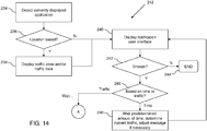
- FIG. 14 provides a flow chart illustrating an example of a set of computer executable operations that may be performed in displaying a traffic reminder notification at 212 ( FIG. 11 ).
- the traffic monitoring module 48 detects the currently displayed application (if any) and determines at 236 if the currently displayed application is location based. If so, the traffic zone being monitored and/or traffic data 26 for the traffic zone is/are displayed at 238.
- the notification user interface 122 may then be displayed at 240, either on its own or in conjunction with the traffic zone and/or traffic data 26.
- the notification user interface 122 may include an OK button 126 to confirm receipt of the notification, and a snooze button 128 to defer the notification.
- the traffic monitoring module 48 may thus determine if the snooze button 128 has been selected. If not, the process ends at 244. If the snooze button 128 has been selected, the traffic monitoring module 48 then determines at 246 whether or not the snooze operation is to be executed according to time (e.g., delay of 10 minutes), or based on the traffic conditions (e.g., do not display again unless traffic is still good after a set period of time).
- time e.g., delay of 10 minutes
- the traffic monitoring module 48 removes the notification user interface 122 from the display of the mobile device 10, waits the predetermined amount of time, determines the current traffic conditions after the delay, and adjusts the notification message 124 for the new current traffic conditions at 248. In this way, the notification user interface 122 may be displayed again at 240 after the associated time delay with updated traffic conditions reported, whether acceptable or unacceptable.
- the traffic monitoring module 48 waits the predetermined amount of time associated with the snooze operation, and then returns to operation 208 shown in FIG. 11 by following path A. It can be appreciated that the operations shown in FIG. 11 may be running periodically and thus path A may instead have the traffic monitoring module 48 continue at its normal periodic monitoring rather than skipping to operation 208 along path A.
- non-mobile devices such as desktop computers.
- providing a notification button 78 in a location based application or web page displayed on a desktop computer can also enable a user to be notified of easing traffic conditions without having to continually consult the application or web page.
- traffic reminder notifications e.g., snooze operations can also be ported or pushed to the mobile device, e.g., if the user plans to leave an office and continue monitoring using a mobile device.
- the mobile device 10 includes a number of components such as a main processor 302 that controls the overall operation of the mobile device 10. Communication functions, including data and voice communications, are performed through a communication subsystem 40.
- the communication subsystem 40 receives messages from and sends messages to a wireless network 16.
- the communication subsystem 40 is configured in accordance with the Global System for Mobile Communication (GSM) and General Packet Radio Services (GPRS) standards, which is used worldwide.
- GSM Global System for Mobile Communication
- GPRS General Packet Radio Services
- 3G and 4G networks such as Enhanced Data-rates for Global Evolution (EDGE), Universal Mobile Telecommunications System (UMTS) and High-Speed Downlink Packet Access (HSDPA), Long Term Evolution (LTE), Worldwide Interoperability for Microwave Access (Wi-Max), etc.
- EDGE Enhanced Data-rates for Global Evolution
- UMTS Universal Mobile Telecommunications System
- HSDPA High-Speed Downlink Packet Access
- LTE Long Term Evolution
- Wi-Max Worldwide Interoperability for Microwave Access
- New standards are still being defined, but it is believed that they will have similarities to the network behavior described herein, and it will also be understood by persons skilled in the art that the examples described herein are intended to use any other suitable standards that are developed in the future.
- the wireless link connecting the communication subsystem 40 with the wireless network 16 represents one or more different Radio Frequency (RF) channels, operating according to defined protocols specified for GSM/GPRS communications.
- RF Radio Frequency
- the main processor 302 also interacts with additional subsystems such as a Random Access Memory (RAM) 306, a flash memory 308, a touch-sensitive display 360, an auxiliary input/output (I/O) subsystem 312, a data port 314, a keyboard 316 (physical, virtual, or both), a speaker 318, a microphone 320, a GPS receiver 46, short-range communications subsystem 326, and other device subsystems 324.
- RAM Random Access Memory
- flash memory 308 a flash memory 308
- I/O auxiliary input/output subsystem
- data port 314 a keyboard 316 (physical, virtual, or both)
- speaker 318 a microphone 320
- GPS receiver 46 short-range communications subsystem 326
- other device subsystems 324 Some of the subsystems of the mobile device 10 perform communication-related functions, whereas other subsystems may provide "resident" or on-device functions.
- the display 42 and the keyboard 316 may be used for both communication-related functions, such as entering a text message for transmission over the wireless network 16, and device-resident functions such as a calculator or task list.
- the mobile device 10 can include a non touch-sensitive display in place of, or in addition to the touch-sensitive display 360.
- the touch-sensitive display 360 can be replaced by a display 42 that may not have touch-sensitive capabilities.
- the mobile device 10 can send and receive communication signals over the wireless network 16 after required network registration or activation procedures have been completed.
- Network access is associated with a subscriber or user of the mobile device 10.
- the mobile device 10 may use a subscriber module component or "smart card” 326, such as a Subscriber Identity Module (SIM), a Removable User Identity Module (RUIM) and a Universal Subscriber Identity Module (USIM).
- SIM Subscriber Identity Module
- RUIM Removable User Identity Module
- USB Universal Subscriber Identity Module
- a SIM/RUIM/USIM 326 is to be inserted into a SIM/RUIM/USIM interface 328 in order to communicate with a network.
- the mobile device 10 is typically a battery-powered device and includes a battery interface 332 for receiving one or more rechargeable batteries 330.
- the battery 330 can be a smart battery with an embedded microprocessor.
- the battery interface 332 is coupled to a regulator (not shown), which assists the battery 330 in providing power to the mobile device 10.
- a regulator not shown
- future technologies such as micro fuel cells may provide the power to the mobile device 10.
- the mobile device 10 also includes an operating system 334 and software components 336 to 342, 12, and 48.
- the operating system 334 and the software components 336 to 346 that are executed by the main processor 302 are typically stored in a persistent store such as the flash memory 308, which may alternatively be a read-only memory (ROM) or similar storage element (not shown).
- ROM read-only memory
- portions of the operating system 334 and the software components 336 to 342, 12, and 48, such as specific device applications, or parts thereof, may be temporarily loaded into a volatile store such as the RAM 306.
- Other software components can also be included, as is well known to those skilled in the art.
- the subset of software applications 336 that control basic device operations, including data and voice communication applications, may be installed on the mobile device 10 during its manufacture.
- Software applications may include a message application 338, a device state module 340, a Personal Information Manager (PIM) 342, a traffic application 12 (see also FIG. 2 ), and a traffic monitoring module 48 (see also FIG. 2 ).
- a message application 338 can be any suitable software program that allows a user of the mobile device 10 to send and receive electronic messages, wherein messages are typically stored in the flash memory 308 of the mobile device 10.
- a device state module 340 provides persistence, i.e.
- a PIM 342 includes functionality for organizing and managing data items of interest to the user, such as, but not limited to, e-mail, contacts, calendar events, and voice mails, and may interact with the wireless network 16.
- software applications or components 339 can also be installed on the mobile device 10. These software applications 339 can be pre-installed applications (i.e. other than message application 338) or third party applications, which are added after the manufacture of the mobile device 10. Examples of third party applications include games, calculators, utilities, etc.
- the additional applications 339 can be loaded onto the mobile device 10 through at least one of the wireless network 16, the auxiliary I/O subsystem 312, the data port 314, the short-range communications subsystem 326, or any other suitable device subsystem 324.
- the data port 314 can be any suitable port that enables data communication between the mobile device 10 and another computing device.
- the data port 314 can be a serial or a parallel port.
- the data port 314 can be a USB port that includes data lines for data transfer and a supply line that can provide a charging current to charge the battery 330 of the mobile device 10.
- received signals are output to the speaker 318, and signals for transmission are generated by the microphone 320.
- voice or audio signal output is accomplished primarily through the speaker 318, the display 42 can also be used to provide additional information such as the identity of a calling party, duration of a voice call, or other voice call related information.
- the touch-sensitive display 360 may be any suitable touch-sensitive display, such as a capacitive, resistive, infrared, surface acoustic wave (SAW) touch-sensitive display, strain gauge, optical imaging, dispersive signal technology, acoustic pulse recognition, and so forth, as known in the art.
- the touch-sensitive display 360 is a capacitive touch-sensitive display which includes a capacitive touch-sensitive overlay 364.
- the overlay 364 may be an assembly of multiple layers in a stack which may include, for example, a substrate, a ground shield layer, a barrier layer, one or more capacitive touch sensor layers separated by a substrate or other barrier, and a cover.
- the capacitive touch sensor layers may be any suitable material, such as patterned indium tin oxide (ITO).
- the display 42 of the touch-sensitive display 360 may include a display area in which information may be displayed, and a non-display area extending around the periphery of the display area. Information is not displayed in the non-display area, which is utilized to accommodate, for example, electronic traces or electrical connections, adhesives or other sealants, and/or protective coatings around the edges of the display area.
- One or more touches may be detected by the touch-sensitive display 360.
- the processor 302 may determine attributes of the touch, including a location of a touch.
- Touch location data may include an area of contact or a single point of contact, such as a point at or near a center of the area of contact, known as the centroid.
- a signal is provided to the controller 366 in response to detection of a touch.
- a touch may be detected from any suitable object, such as a finger, thumb, appendage, or other items, for example, a stylus, pen, or other pointer, depending on the nature of the touch-sensitive display 360.
- the location of the touch moves as the detected object moves during a touch.
- the controller 366 and/or the processor 302 may detect a touch by any suitable contact member on the touch-sensitive display 360. Similarly, multiple simultaneous touches, are detected.
- One or more gestures are also detected by the touch-sensitive display 360.
- a gesture is a particular type of touch on a touch-sensitive display 360 that begins at an origin point and continues to an end point.
- a gesture may be identified by attributes of the gesture, including the origin point, the end point, the distance travelled, the duration, the velocity, and the direction, for example.
- a gesture may be long or short in distance and/or duration. Two points of the gesture may be utilized to determine a direction of the gesture.
- a gesture is a swipe (also known as a "flick").
- a swipe has a single direction.
- the touch-sensitive overlay 364 may evaluate swipes with respect to the origin point at which contact is initially made with the touch-sensitive overlay 364 and the end point at which contact with the touch-sensitive overlay 364 ends rather than using each of location or point of contact over the duration of the gesture to resolve a direction.
- swipes include a horizontal swipe, a vertical swipe, and a diagonal swipe.
- a horizontal swipe typically comprises an origin point towards the left or right side of the touch-sensitive overlay 364 to initialize the gesture, a horizontal movement of the detected object from the origin point to an end point towards the right or left side of the touch-sensitive overlay 364 while maintaining continuous contact with the touch-sensitive overlay 364, and a breaking of contact with the touch-sensitive overlay 364.
- a vertical swipe typically comprises an origin point towards the top or bottom of the touch-sensitive overlay 364 to initialize the gesture, a horizontal movement of the detected object from the origin point to an end point towards the bottom or top of the touch-sensitive overlay 364 while maintaining continuous contact with the touch-sensitive overlay 364, and a breaking of contact with the touch-sensitive overlay 364.
- Swipes can be of various lengths, can be initiated in various places on the touch-sensitive overlay 364, and need not span the full dimension of the touch-sensitive overlay 364.
- breaking contact of a swipe can be gradual in that contact with the touch-sensitive overlay 364 is gradually reduced while the swipe is still underway.
- Meta-navigation gestures may also be detected by the touch-sensitive overlay 364.
- a meta-navigation gesture is a gesture that has an origin point that is outside the display area of the touch-sensitive overlay 364 and that moves to a position on the display area of the touch-sensitive display. Other attributes of the gesture may be detected and be utilized to detect the meta-navigation gesture.
- Meta-navigation gestures may also include multi-touch gestures in which gestures are simultaneous or overlap in time and at least one of the touches has an origin point that is outside the display area and moves to a position on the display area of the touch-sensitive overlay 364. Thus, two fingers may be utilized for meta-navigation gestures. Further, multi-touch meta-navigation gestures may be distinguished from single touch meta-navigation gestures and may provide additional or further functionality.
- an optional force sensor 370 or force sensors is disposed in any suitable location, for example, between the touch-sensitive display 360 and a back of the mobile device 10 to detect a force imparted by a touch on the touch-sensitive display 360.
- the force sensor 370 may be a force-sensitive resistor, strain gauge, piezoelectric or piezoresistive device, pressure sensor, or other suitable device.
- Force as utilized throughout the specification refers to force measurements, estimates, and/or calculations, such as pressure, deformation, stress, strain, force density, force-area relationships, thrust, torque, and other effects that include force or related quantities.
- Force information related to a detected touch may be utilized to select information, such as information associated with a location of a touch. For example, a touch that does not meet a force threshold may highlight a selection option, whereas a touch that meets a force threshold may select or input that selection option.
- Selection options include, for example, displayed or virtual keys of a keyboard; selection boxes or windows, e.g., "cancel,” “delete,” or “unlock”; function buttons, such as play or stop on a music player; and so forth.
- Different magnitudes of force may be associated with different functions or input. For example, a lesser force may result in panning, and a higher force may result in zooming.
- any module or component exemplified herein that executes instructions may include or otherwise have access to computer readable media such as storage media, computer storage media, or data storage devices (removable and/or non-removable) such as, for example, magnetic disks, optical disks, or tape.
- Computer storage media may include volatile and non-volatile, removable and non-removable media implemented in any method or technology for storage of information, such as computer readable instructions, data structures, program modules, or other data.
- Examples of computer storage media include RAM, ROM, EEPROM, flash memory or other memory technology, CD-ROM, digital versatile disks (DVD) or other optical storage, magnetic cassettes, magnetic tape, magnetic disk storage or other magnetic storage devices, or any other medium which can be used to store the desired information and which can be accessed by an application, module, or both. Any such computer storage media may be part of the mobile device 10, any component of or related to the communication system 8, network infrastructure 22, etc., or accessible or connectable thereto. Any application or module herein described may be implemented using computer readable/executable instructions that may be stored or otherwise held by such computer readable media.
Abstract
Description
- The following relates to systems and methods for providing traffic notifications.
- Drivers such as commuters, when possible, typically attempt to avoid heavy traffic. Even when drivers are aware of heavy traffic in a particular area, e.g., via a news report, traffic feed, etc., there are no alternative routes available. For example, a commuter's route home may include a segment of a highway that has no viable alternative due to a bridge, mountain, construction, etc.
- Users of mobile electronic communication devices ("mobile devices" hereinafter) such as smart phones, tablet computers, portable global positioning system (GPS) units, in-vehicle navigation systems, and the like, are often able to monitor traffic to both obtain directions, and traffic status updates.
- There is provided a method of providing traffic reminder notifications, the method comprising: detecting selection of an input mechanism; determining traffic data to be monitored according to the selection; determining an acceptable traffic condition in a traffic zone by monitoring the traffic data; and displaying a traffic reminder notification.
- There is also provided an electronic device comprising a processor, a memory, and a display, the memory comprising computer executable instructions for providing traffic reminder notifications, the computer executable instructions comprising instructions for: detecting selection of an input mechanism; determining traffic data to be monitored according to the selection; determining an acceptable traffic condition in a traffic zone by monitoring the traffic data; and displaying a traffic reminder notification.
- There is also provided a computer readable storage medium comprising computer executable instructions for providing traffic reminder notifications, the computer executable instructions comprising instructions for: detecting selection of an input mechanism; determining traffic data to be monitored according to the selection; determining an acceptable traffic condition in a traffic zone by monitoring the traffic data; and displaying a traffic reminder notification.
- Embodiments will now be described by way of example only with reference to the appended drawings wherein:
-
FIG. 1 is a schematic diagram of a communication system; -
FIG. 2 is a block diagram of an example of a configuration for a mobile device having multiple location-based applications; -
FIG. 3 is a screen shot of an example of a traffic application user interface; -
FIG. 4 is a screen shot of an example of a traffic application user interface; -
FIG. 5 is a screen shot of an example of a maps application user interface including traffic information; -
FIG. 6 is a screen shot of an example of a maps application user interface; -
FIG. 7 is a screen shot of an example of a navigation application user interface showing a specified route; -
FIG. 8 is a screen shot showing an example of a traffic reminder notification being displayed; -
FIG. 9 is a screen shot showing an example of a menu of options including an option to trigger a traffic reminder notification; -
FIG. 10 is a screen shot showing an example of a user interface for selecting a route to monitor in association with a traffic reminder notification; -
FIG. 11 is a flow chart illustrating an example of a set of computer executable operations that may be performed in enabling a traffic reminder notification to be triggered and subsequently displayed; -
FIG. 12 is a flow chart illustrating an example of a set of computer executable operations that may be performed in detecting acceptable traffic conditions; -
FIG. 13 is a flow chart illustrating an example of a set of computer executable operations that may be performed in determining status of segments in a traffic zone; -
FIG. 14 is a flow chart illustrating an example of a set of computer executable operations that may be performed in displaying a traffic reminder notification; and -
FIG. 15 is a block diagram of an example of a configuration for a mobile device. - It will be appreciated that for simplicity and clarity of illustration, where considered appropriate, reference numerals may be repeated among the figures to indicate corresponding or analogous elements. In addition, numerous specific details are set forth in order to provide a thorough understanding of the examples described herein. However, it will be understood by those of ordinary skill in the art that the examples described herein may be practiced without these specific details. In other instances, well-known methods, procedures and components have not been described in detail so as not to obscure the examples described herein. Also, the description is not to be considered as limiting the scope of the examples described herein.
- It will be appreciated that the examples and corresponding diagrams used herein are for illustrative purposes only. Different configurations and terminology can be used without departing from the principles expressed herein. For instance, components and modules can be added, deleted, modified, or arranged with differing connections without departing from these principles.
- Although drivers may have access to traffic-related applications on a mobile device, typically the relevant traffic data is reported within an application, e.g., via a table, chart, or map route. In order to be aware of developing traffic conditions in a particular area of traffic or route, the user may be required to either keep the traffic-related application open and running, or periodically consult the traffic data provided by the traffic application.
- It has been found that while having a traffic-related application open/running while driving is convenient. However, when an individual has not yet commenced driving, having the application running, or periodically checking the traffic data is not particularly convenient because it can be time-consuming. For example, a commuter that is about to leave work to head home may consult their mobile device or other electronic device to determine traffic conditions before leaving. If that commuter has the option to leave when traffic eases, they may need to frequently monitor the traffic data to determine when is a suitable time to leave.
- To address the above drawbacks, a reminder notification is provided that, when set, enables a user to continue with what they had been doing until the mobile device can determine that the traffic conditions have improved. The ability to trigger the reminder notification can be provided in a location-based application such as a maps application, navigation application, or traffic application. Additionally, the ability to trigger the reminder notification can be provided by a module, widget, service, user interface element, or application outside of the location-based applications, to enable the user to trigger the reminder at a convenient time rather than based only on the detection of poor traffic conditions. In this way, the user can trigger the reminder notification when they are thinking of leaving, from within any application or screen that they are currently using.
- Additionally, the ability to trigger the reminder notification can be provided in connection with a periodic or otherwise recurring reminder or prompt. For example, a button or option can be included in a calendar reminder having an embedded location that is triggered to alert a driver when it is time to leave, to enable the driver to postpone the calendar reminder to coincide with more favorable traffic conditions, i.e., "better traffic". As such, it can be appreciated that an application or core notification system can be responsible for managing the reminder notification.
- By accessing traffic data that this already available to one or more applications on the mobile device, the notification reminder can also be provided as an additional layer on top of an application or operating system without having to develop a new application or modify an existing application. Such a layer can be transparent to the user until a reminder notification is displayed, or provided as a link, widget or other user interface element, for example, in a home screen.
- Turning now to
FIG. 1 , an example of acommunication system 8 is shown. In this example, thecommunication 8 includes amobile device 10, which has atraffic application 12. Themobile device 10 is operable to communicate with atraffic application server 14 via awireless network 16. Thewireless network 16 is part of anetwork infrastructure 22. It can be appreciated that thewireless network 16 andnetwork infrastructure 22 in the example shown inFIG. 1 are for illustrative purposes only. - The
mobile device 10 provideslocation data 18 androute data 20 to thetraffic application server 14 and obtainsapplication updates 24, e.g., traffic updates, navigation directions, etc., for using thetraffic application 12. As shown inFIG. 1 , thenetwork infrastructure 22 may also providelocation data 18 using, for example, cell tower triangulation or other processes for determining an estimated location for themobile device 10. Thelocation data 18 provided by themobile device 10, may be obtained from, for example, a GPS network (not shown) or using other location finding techniques. Theroute data 20 may include start point and end point coordinates for calculating a route, or may provide the route itself for obtainingtraffic data 26 in association with segments along that route. - The
traffic application server 14 may generate theapplication updates 24 using various sources of information.FIG. 1 provides two example sources, atraffic data server 28 providingtraffic data 26, and anews feed 32 providingnews data 30. It can be appreciated that the data sources and system configuration shown inFIG. 1 are for illustrative purposes only and various other configurations may be possible. For example, thetraffic application server 14 may include its owntraffic data service 28. Alternatively, thetraffic application 12 may be operable to communicate directly with thetraffic data service 28 and/ornews feed 30 in order to obtain data which may, collectively, provide application updates 24. -
FIG. 2 illustrates an example of a configuration for themobile device 10. Themobile device 10 includes acommunication subsystem 40 for sending and receiving data via thewireless network 16, and includes a display module (display) 42 for rendering graphical user interfaces on a physical display of themobile device 10. It can be appreciated that thedisplay 42 may also act as an input mechanism, e.g., via touch-sensitivity. Further details concerning various input mechanisms available to themobile device 10 are described below and shown inFIG. 15 . Thetraffic application 12 is also shown inFIG. 2 and includes or otherwise has access to atraffic data store 44 for storingtraffic data 26, application updates 24, etc. Thetraffic application 12 also includes atraffic monitoring module 48 for enabling a traffic reminder notification to be triggered, for monitoringtraffic data 26 and/or application updates 24 to determine when traffic conditions in a particular "traffic zone" have improved, and for enabling the traffic reminder notification to be displayed. Traffic zones, as used herein, may refer to any route or geographical area of interest that is to be monitored. Traffic zones may include various numbers of streets, landmarks, and other data provided by a particular application, such as thetraffic application 12. Thetraffic application 12 and/ortraffic monitoring module 48 is/are also communicable with aGPS receiver 46 for obtaininglocation data 18 for themobile device 10. - The
traffic monitoring module 48 may also be external to any particular application as shown in dashed lines inFIG. 2 . For example, thetraffic monitoring module 48 may also be operable to enable the traffic reminder notification to be triggered and displayed in association with other location based applications, such as thenavigation application 52 andmap application 50 shown inFIG. 2 , or from within or in association with various other applications, screens, etc. For example, thetraffic monitoring module 48 may be linked to an option provided in a menu or other input mechanism in a widget, home screen, messaging application, web browser, etc. In this way, thetraffic monitoring module 48 may serve multiple applications and/or be operable across an operating system to provide traffic reminder notifications independent of where the user is currently interacting with themobile device 10. -
FIG. 3 illustrates an example of a trafficapplication user interface 70. The trafficapplication user interface 70 includes one ormore route summaries 72. Eachroute summary 72displays route information 74, such as the type of route (direct, shortest distance, fastest, etc.), arrival time, waypoints or segments along the route (e.g., street names), distance, total time, etc. Theroute summary 72 also includes achart 76 including one ormore segments 77. In the example trafficapplication user interface 70 shown inFIG. 3 , eachsegment 77 is color coded to show relative traffic conditions along each segment. For example, as shown, eachsegment 77 may be colored green when traffic is good, yellow when traffic is slower than normal, and red when traffic is slow or stopped. By color coding thesegments 77, the user can identify where along the route potential traffic congestion is likely to occur. - The
route summary 72 also includes anotification button 78 that is displayed to enable the user to trigger a traffic reminder notification. In the example shown inFIG. 3 , thenotification button 78 is labeled "Notify When Traffic Good", but various other labels may be used to signify that selection of thenotification button 78 results in triggering a traffic reminder notification. - When only one route is available, as shown in
FIG. 3 , the trafficapplication user interface 70 may include a no alternative routes foundportion 80. The trafficapplication user interface 70 also includes anupdate routes button 82 to enable theroute summaries 72 to be updated withfresh traffic data 26 by obtaining new application updates 24. -
FIG. 4 illustrates another example screen shot of the trafficapplication user interface 70 wherein tworoute summaries 72 are displayed. In the example shown inFIG. 4 , both a direct route and an alternate route are shown withcorresponding route information 74, andtraffic charts 76. To enable the user to trigger a traffic reminder notification in association with any available route for a particular traffic zone, thenotification button 78 may be displayed in association with eachroute summary 72. - By providing the
notification button 78 within thetraffic application 12, when a user is viewing a particular route or routes between a start point (e.g., current location), and an end point (e.g., home), and traffic conditions are not currently favorable, the user can select thenotification button 78 to be subsequently reminded when the traffic conditions for that traffic zone have improved. This avoids the user having to periodically access thetraffic application 12, select the route of interest, and monitor the traffic conditions. Instead, the traffic reminder notification can be triggered to advise the user when the traffic conditions appear to be better, at which time the user may access thetraffic application 12 to confirm their route, choose a new route, or may simply begin driving based on the notification, to name a few examples. - As discussed above, the
traffic monitoring module 48 may also monitor traffic zones that correspond to a particular geographical area. A mapapplication user interface 90 is shown inFIG. 5 , whereintraffic data 26 is fed to and displayed within amap area 92. In the example shown inFIG. 5 ,traffic segments 94 are inserted along streets within themap area 92 and, similar to the trafficapplication user interface 70, are color coded. Themap area 92 also includes acurrent location identifier 96 and thenotification button 78 for triggering a traffic reminder notification in association with the currentlyviewable map area 92.FIG. 5 illustrates an example wherein a commuter is currently at work and is interested in determining local traffic conditions surrounding their place of work. The commuter may consult thetraffic segments 94 shown in themap area 92 to determine when to leave work. Rather than periodically accessing the mapapplication user interface 90 to determine when traffic has eased, the commuter may instead select thenotification button 78 to trigger a traffic reminder notification when traffic is better, e.g., when the currentred segments 94 change to yellow or green. - The
notification button 78 may also be displayed in a mapapplication user interface 100 that does not include traffic information, e.g., as shown inFIG. 6 . Providing thenotification button 78 in the mapapplication user interface 100, a user may zoom in or out to define ageographical map area 102 that is of interest, e.g., surrounding their current location as specified by acurrent location identifier 104, and have thetraffic monitoring module 48 notify the user when traffic is considered "good" in that area. This defined area of interest may relate to only a portion of the user's total planned journey. - A navigation
application user interface 110 may also include thenotification button 78 as shown inFIG. 7 . In this way, after selecting and generating a route between points A and B, the user may select thenotification button 78 to have thetraffic monitoring module 48 notify the user when traffic is acceptable. For example, a user that is about to leave on an extended trip may select thenotification button 78 to determine an appropriate time to leave, based on traffic conditions. - An example of a traffic reminder notification user interface ("notification user interface" hereinafter) 122 is shown in
FIG. 8 . In the example shown inFIG. 8 , thenotification user interface 122 is displayed within adisplay screen 120, shown generically inFIG. 8 to illustrate that thenotification user interface 122 can be displayed in any screen to provide the traffic notification reminder independent of location based applications or the application from which thenotification button 78 has been selected. Thenotification user interface 122 includes a notification message 124 (in this example: "Traffic on selected route or in selected area is clear!"), anOK button 126 to confirm the reminder, and asnooze button 128 to defer the reminder. Thesnooze button 128 can be used to, for example, have the notification reminder repeated at a later time. It can be appreciated that thesnooze button 128, when selected, may cause thetraffic monitoring module 48 to operate according to predetermined criteria, or may cause an additional user interface (not shown) to be displayed which enables selection of a particular "snooze time". For example, a predetermined criterion for the snooze operation may include the later of 10 minutes or next indication that traffic is good. - The
snooze button 128 can also trigger a follow up reminder that indicates, at a predetermined subsequent time, the current status of the traffic conditions in the associated traffic zone. For example, the user may select thesnooze button 128, which causes a delay in the traffic reminder notification of 10 minutes. However, in the intervening 10 minutes, traffic may have deteriorated. Rather than delaying the snooze operation until traffic again improves, thenotification user interface 122 may be modified to include areminder message 124 that indicates traffic has worsened and enable a further snooze or option to not notify the user again until traffic is acceptable. Therefore, it can be appreciated that thenotification user interface 122 can be used to provide a control console for managing the propagation of traffic reminders into the future to accommodate changing conditions in the users schedule and changing traffic conditions based on that schedule. - In addition to providing the
notification button 78, a traffic reminder notification can also be triggered using other input mechanisms. For example, a menu ofoptions 146 may be invoked from a homescreen user interface 140 as shown inFIG. 9 . The menu ofoptions 146 includes a traffic notification option 148 (labeled: "Notify Me When Traffic Good") that, when selected, triggers the traffic reminder notification in a manner similar to selecting thenotification button 78. When triggered independent of a location-based application, the traffic notification reminder may need to be associated with a particular traffic zone, such as a geographical area or route. Selection of thetraffic notification option 148 may, for example, initiate a location based application in order to have the user select a traffic zone, or may, as shown inFIG. 10 , enable selection from predetermined traffic zones such as saved routes. It can be appreciated that thetraffic monitoring module 48 may obtain saved routes or other traffic zones from, for example, thenavigation application 52,traffic application 12,map application 50, etc.; or may provide a user interface to enable a user to customize routes for the traffic reminder notifications. - Referring to
FIG. 10 , a routeselection user interface 160 is shown, which may be displayed by thetraffic monitoring module 48 after detecting selection of thetraffic notification option 148. The routeselection user interface 160 includes alist 162 of predefined routes and aset route button 164. By selecting one of the routes from thelist 162,traffic data 26 associated with segments within that route are referenced by thetraffic monitoring module 48 in determining when to display a traffic reminder notification. By selecting theset route button 164, the user is provided with an opportunity to define a route. For example, a separate user interface (not shown) may be displayed enabling the user to specify start and end points, geographical areas, etc. By selecting anOK button 166, a selected or defined route can be accepted. - As discussed above, the traffic reminder notification may be controlled and triggered in various ways, using various mechanisms. In addition to the examples shown in
FIGS. 1-10 , it can be appreciated that other user interface elements may be used. For example, thehome screen 140 shown inFIG. 9 may be adapted to include an icon or other visual element in the banner (upper) portion that indicates when traffic is acceptable, in a manner similar to the way in which identifiers are displayed for new incoming messages, calendar appointments, and the like. Similarly, thenotification button 78 may be included directly in thehome screen 140 or layered over any other application currently running. The provision of thenotification button 78 can also be tied to daily events or other reminders. For example, a daily calendar reminder can be used to have a first reminder that the time to leave has arrived and thenotification button 78 included to enable the traffic reminder notification to be triggered. Such a calendar reminder can include a destination location or other geographical location to enable thetraffic monitoring module 48 to determine whattraffic data 26 to reference. Thehome screen 140 or other application screen may also include a traffic widget that provides the functionalities herein described in a separate, standalone user interface element, to further facilitate the use of the traffic reminder notification at any time, from anywhere in the user interface flow. -
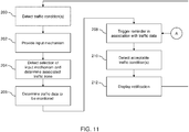
FIG. 11 provides a flow chart illustrating an example of a set of computer executable operations that may be performed in enabling a traffic reminder notification to be triggered and subsequently displayed by thetraffic monitoring module 48. The operations shown by way of example inFIG. 11 may be executed automatically while a location based application is running and/or while such an application is in the foreground of the display of themobile device 10. For example, at 200, traffic conditions may be detected while a location based application is running, at which time an input mechanism such as thenotification button 78 is displayed at 202. The operations may also begin at 202, wherein a user initiates the menu ofoptions 146, thenotification button 78 is always displayed, etc. After providing the input mechanism at 202, thetraffic monitoring module 48 detects at 204, a selection of the input mechanism and determines an associated traffic zone. This may include capturing a currently viewable map area, determining a currently viewable route, enabling selection of a predetermined route, enabling a new route to be defined, etc. After the associated traffic zone is determined at 204, thetraffic monitoring module 48 determines thetraffic data 26 and/or application updates 24 that should be monitored in order to determine if a traffic condition is acceptable thus warranting a traffic reminder notification. - The
traffic monitoring module 48 may then trigger a reminder in association with thedetermined traffic data 26 at 208 in order to enable detection of acceptable traffic conditions at 210. For example, after triggering a reminder at 208, thetraffic monitoring module 48 may then monitorapplication updates 24 fed by thetraffic application server 14 to determine when predetermined criteria have been met, e.g., when segments in the traffic zone are green. After detecting that traffic conditions are acceptable at 210, thetraffic monitoring module 48 displays the traffic reminder notification at 212, e.g., by displaying thenotification user interface 122 shown inFIG. 8 . -
FIG. 12 provides a flow chart illustrating an example of a set of computer executable operations that may be performed in detecting acceptable traffic conditions at 210. At 214, thetraffic monitoring module 48 obtains a traffic update (e.g., via anapplication update 24 provided by the traffic application server 14), and determines the status of segments in the associated traffic zone at 216. As discussed above, each traffic zone may include a number of segments along a route or within a particular geographical area, each segment typically comprising a length of roadway. In this example, data associated with each segment is provided and indicates the traffic conditions in or along that segment. For example, during rush hour, traffic moving along a particular segment may be moving at less than 10 mph on average in a 55 mph speed zone, indicating congested traffic. At 218, thetraffic monitoring module 48 determines if thetraffic data 26 is indicative of an acceptable traffic status. If not, the process ends at 220. If the traffic is determined to be acceptable in the traffic zone being monitored, the traffic reminder notification is initiated at 222. -
FIG. 13 provides a flow chart illustrating an example of a set of computer executable operations that may be performed in determining statuses of segments in a traffic zone at 216. In the example shown inFIG. 13 , it is assumed that application updates 24 are provided by thetraffic application server 14, which report a green, yellow, or red status for various traffic segments. At 224, thetraffic monitoring module 48 examines the segments for the traffic zone being monitored and determines at 226 if any of the segments are red 226. If one or more of the segments are red, indicating slow traffic in at least one portion of the traffic zone, thetraffic monitoring module 48 then determines at 230 if any of the red segments are greater in distance than a predetermined threshold. For example, to avoid reporting poor traffic conditions due to stop lights or other relatively minor delays, thetraffic monitoring module 48 may filter for only red segments that are longer than a predetermined distance, e.g., 100 yards. If at least one red segment is above the threshold, the status of the traffic conditions is set to be unacceptable at 232. If there are no red segments above the threshold, the status of the traffic conditions is set to be acceptable at 228. - It can be appreciated that various other processes or algorithms may be used to determine if traffic is acceptable according to traffic data and other information available to the
mobile device 10; and such processes and algorithms can apply rigid rules or incorporate user preferences, options, selections, behaviors, etc. One way to determine if traffic is acceptable to a particular driver is to have the driver select tolerances or preferences for what constitutes "bad traffic". For example, some drivers may find a few severe slow downs in traffic to be more acceptable than an overall slow pace along an entire route. By taking such preferences into consideration, one route that has a reasonable pace on average may not be considered acceptable traffic, due to several short severe slowdowns; whereas another route that has a relatively slow pace overall, but without any severe slowdowns, is considered acceptable traffic. -
FIG. 14 provides a flow chart illustrating an example of a set of computer executable operations that may be performed in displaying a traffic reminder notification at 212 (FIG. 11 ). At 234, thetraffic monitoring module 48 detects the currently displayed application (if any) and determines at 236 if the currently displayed application is location based. If so, the traffic zone being monitored and/ortraffic data 26 for the traffic zone is/are displayed at 238. Thenotification user interface 122 may then be displayed at 240, either on its own or in conjunction with the traffic zone and/ortraffic data 26. As discussed above, thenotification user interface 122 may include anOK button 126 to confirm receipt of the notification, and asnooze button 128 to defer the notification. While thenotification user interface 122 is being displayed thetraffic monitoring module 48 may thus determine if thesnooze button 128 has been selected. If not, the process ends at 244. If thesnooze button 128 has been selected, thetraffic monitoring module 48 then determines at 246 whether or not the snooze operation is to be executed according to time (e.g., delay of 10 minutes), or based on the traffic conditions (e.g., do not display again unless traffic is still good after a set period of time). If the snooze operation is to be executed based on time, thetraffic monitoring module 48 removes thenotification user interface 122 from the display of themobile device 10, waits the predetermined amount of time, determines the current traffic conditions after the delay, and adjusts thenotification message 124 for the new current traffic conditions at 248. In this way, thenotification user interface 122 may be displayed again at 240 after the associated time delay with updated traffic conditions reported, whether acceptable or unacceptable. - If the snooze operation is based on the traffic conditions, the
traffic monitoring module 48 waits the predetermined amount of time associated with the snooze operation, and then returns tooperation 208 shown inFIG. 11 by following path A. It can be appreciated that the operations shown inFIG. 11 may be running periodically and thus path A may instead have thetraffic monitoring module 48 continue at its normal periodic monitoring rather than skipping tooperation 208 along path A. - It can therefore be appreciated that by enabling a
notification button 78,traffic notification option 148, or other input mechanism to be provided both internal and external to location based applications, a user may be notified of changes in traffic conditions without having to periodically consult such location based applications. - The principles discussed above may also be applicable to other devices, including "non-mobile" devices such as desktop computers. For example, providing a
notification button 78 in a location based application or web page displayed on a desktop computer can also enable a user to be notified of easing traffic conditions without having to continually consult the application or web page. If that user also has a mobile device that is communicable with the desktop computer, it can be appreciated that traffic reminder notifications, e.g., snooze operations can also be ported or pushed to the mobile device, e.g., if the user plans to leave an office and continue monitoring using a mobile device. - Referring to
FIG. 15 , to further aid in the understanding of the examplemobile devices 10 described above, shown therein is a block diagram of an example configuration of amobile device 10. Themobile device 10 includes a number of components such as amain processor 302 that controls the overall operation of themobile device 10. Communication functions, including data and voice communications, are performed through acommunication subsystem 40. Thecommunication subsystem 40 receives messages from and sends messages to awireless network 16. In this example of themobile device 10, thecommunication subsystem 40 is configured in accordance with the Global System for Mobile Communication (GSM) and General Packet Radio Services (GPRS) standards, which is used worldwide. Other communication configurations that are equally applicable are the 3G and 4G networks such as Enhanced Data-rates for Global Evolution (EDGE), Universal Mobile Telecommunications System (UMTS) and High-Speed Downlink Packet Access (HSDPA), Long Term Evolution (LTE), Worldwide Interoperability for Microwave Access (Wi-Max), etc. New standards are still being defined, but it is believed that they will have similarities to the network behavior described herein, and it will also be understood by persons skilled in the art that the examples described herein are intended to use any other suitable standards that are developed in the future. The wireless link connecting thecommunication subsystem 40 with thewireless network 16 represents one or more different Radio Frequency (RF) channels, operating according to defined protocols specified for GSM/GPRS communications. - The
main processor 302 also interacts with additional subsystems such as a Random Access Memory (RAM) 306, aflash memory 308, a touch-sensitive display 360, an auxiliary input/output (I/O)subsystem 312, adata port 314, a keyboard 316 (physical, virtual, or both), aspeaker 318, amicrophone 320, aGPS receiver 46, short-range communications subsystem 326, andother device subsystems 324. Some of the subsystems of themobile device 10 perform communication-related functions, whereas other subsystems may provide "resident" or on-device functions. By way of example, thedisplay 42 and thekeyboard 316 may be used for both communication-related functions, such as entering a text message for transmission over thewireless network 16, and device-resident functions such as a calculator or task list. In one example, themobile device 10 can include a non touch-sensitive display in place of, or in addition to the touch-sensitive display 360. For example the touch-sensitive display 360 can be replaced by adisplay 42 that may not have touch-sensitive capabilities. - The
mobile device 10 can send and receive communication signals over thewireless network 16 after required network registration or activation procedures have been completed. Network access is associated with a subscriber or user of themobile device 10. To identify a subscriber, themobile device 10 may use a subscriber module component or "smart card" 326, such as a Subscriber Identity Module (SIM), a Removable User Identity Module (RUIM) and a Universal Subscriber Identity Module (USIM). In the example shown, a SIM/RUIM/USIM 326 is to be inserted into a SIM/RUIM/USIM interface 328 in order to communicate with a network. - The
mobile device 10 is typically a battery-powered device and includes abattery interface 332 for receiving one or morerechargeable batteries 330. In at least some examples, thebattery 330 can be a smart battery with an embedded microprocessor. Thebattery interface 332 is coupled to a regulator (not shown), which assists thebattery 330 in providing power to themobile device 10. Although current technology makes use of a battery, future technologies such as micro fuel cells may provide the power to themobile device 10. - The
mobile device 10 also includes anoperating system 334 andsoftware components 336 to 342, 12, and 48. Theoperating system 334 and thesoftware components 336 to 346 that are executed by themain processor 302 are typically stored in a persistent store such as theflash memory 308, which may alternatively be a read-only memory (ROM) or similar storage element (not shown). Those skilled in the art will appreciate that portions of theoperating system 334 and thesoftware components 336 to 342, 12, and 48, such as specific device applications, or parts thereof, may be temporarily loaded into a volatile store such as theRAM 306. Other software components can also be included, as is well known to those skilled in the art. - The subset of
software applications 336 that control basic device operations, including data and voice communication applications, may be installed on themobile device 10 during its manufacture. Software applications may include amessage application 338, adevice state module 340, a Personal Information Manager (PIM) 342, a traffic application 12 (see alsoFIG. 2 ), and a traffic monitoring module 48 (see alsoFIG. 2 ). Amessage application 338 can be any suitable software program that allows a user of themobile device 10 to send and receive electronic messages, wherein messages are typically stored in theflash memory 308 of themobile device 10. Adevice state module 340 provides persistence, i.e. thedevice state module 340 ensures that important device data is stored in persistent memory, such as theflash memory 308, so that the data is not lost when themobile device 10 is turned off or loses power. APIM 342 includes functionality for organizing and managing data items of interest to the user, such as, but not limited to, e-mail, contacts, calendar events, and voice mails, and may interact with thewireless network 16. - Other types of software applications or
components 339 can also be installed on themobile device 10. Thesesoftware applications 339 can be pre-installed applications (i.e. other than message application 338) or third party applications, which are added after the manufacture of themobile device 10. Examples of third party applications include games, calculators, utilities, etc. - The
additional applications 339 can be loaded onto themobile device 10 through at least one of thewireless network 16, the auxiliary I/O subsystem 312, thedata port 314, the short-range communications subsystem 326, or any othersuitable device subsystem 324. - The
data port 314 can be any suitable port that enables data communication between themobile device 10 and another computing device. Thedata port 314 can be a serial or a parallel port. In some instances, thedata port 314 can be a USB port that includes data lines for data transfer and a supply line that can provide a charging current to charge thebattery 330 of themobile device 10. - For voice communications, received signals are output to the
speaker 318, and signals for transmission are generated by themicrophone 320. Although voice or audio signal output is accomplished primarily through thespeaker 318, thedisplay 42 can also be used to provide additional information such as the identity of a calling party, duration of a voice call, or other voice call related information. - The touch-
sensitive display 360 may be any suitable touch-sensitive display, such as a capacitive, resistive, infrared, surface acoustic wave (SAW) touch-sensitive display, strain gauge, optical imaging, dispersive signal technology, acoustic pulse recognition, and so forth, as known in the art. In the presently described example, the touch-sensitive display 360 is a capacitive touch-sensitive display which includes a capacitive touch-sensitive overlay 364. Theoverlay 364 may be an assembly of multiple layers in a stack which may include, for example, a substrate, a ground shield layer, a barrier layer, one or more capacitive touch sensor layers separated by a substrate or other barrier, and a cover. The capacitive touch sensor layers may be any suitable material, such as patterned indium tin oxide (ITO). - The
display 42 of the touch-sensitive display 360 may include a display area in which information may be displayed, and a non-display area extending around the periphery of the display area. Information is not displayed in the non-display area, which is utilized to accommodate, for example, electronic traces or electrical connections, adhesives or other sealants, and/or protective coatings around the edges of the display area. - One or more touches, also known as touch contacts or touch events, may be detected by the touch-
sensitive display 360. Theprocessor 302 may determine attributes of the touch, including a location of a touch. Touch location data may include an area of contact or a single point of contact, such as a point at or near a center of the area of contact, known as the centroid. A signal is provided to thecontroller 366 in response to detection of a touch. A touch may be detected from any suitable object, such as a finger, thumb, appendage, or other items, for example, a stylus, pen, or other pointer, depending on the nature of the touch-sensitive display 360. The location of the touch moves as the detected object moves during a touch. Thecontroller 366 and/or theprocessor 302 may detect a touch by any suitable contact member on the touch-sensitive display 360. Similarly, multiple simultaneous touches, are detected. - One or more gestures are also detected by the touch-
sensitive display 360. A gesture is a particular type of touch on a touch-sensitive display 360 that begins at an origin point and continues to an end point. A gesture may be identified by attributes of the gesture, including the origin point, the end point, the distance travelled, the duration, the velocity, and the direction, for example. A gesture may be long or short in distance and/or duration. Two points of the gesture may be utilized to determine a direction of the gesture. - An example of a gesture is a swipe (also known as a "flick"). A swipe has a single direction. The touch-
sensitive overlay 364 may evaluate swipes with respect to the origin point at which contact is initially made with the touch-sensitive overlay 364 and the end point at which contact with the touch-sensitive overlay 364 ends rather than using each of location or point of contact over the duration of the gesture to resolve a direction. - Examples of swipes include a horizontal swipe, a vertical swipe, and a diagonal swipe. A horizontal swipe typically comprises an origin point towards the left or right side of the touch-
sensitive overlay 364 to initialize the gesture, a horizontal movement of the detected object from the origin point to an end point towards the right or left side of the touch-sensitive overlay 364 while maintaining continuous contact with the touch-sensitive overlay 364, and a breaking of contact with the touch-sensitive overlay 364. Similarly, a vertical swipe typically comprises an origin point towards the top or bottom of the touch-sensitive overlay 364 to initialize the gesture, a horizontal movement of the detected object from the origin point to an end point towards the bottom or top of the touch-sensitive overlay 364 while maintaining continuous contact with the touch-sensitive overlay 364, and a breaking of contact with the touch-sensitive overlay 364. - Swipes can be of various lengths, can be initiated in various places on the touch-
sensitive overlay 364, and need not span the full dimension of the touch-sensitive overlay 364. In addition, breaking contact of a swipe can be gradual in that contact with the touch-sensitive overlay 364 is gradually reduced while the swipe is still underway. - Meta-navigation gestures may also be detected by the touch-
sensitive overlay 364. A meta-navigation gesture is a gesture that has an origin point that is outside the display area of the touch-sensitive overlay 364 and that moves to a position on the display area of the touch-sensitive display. Other attributes of the gesture may be detected and be utilized to detect the meta-navigation gesture. Meta-navigation gestures may also include multi-touch gestures in which gestures are simultaneous or overlap in time and at least one of the touches has an origin point that is outside the display area and moves to a position on the display area of the touch-sensitive overlay 364. Thus, two fingers may be utilized for meta-navigation gestures. Further, multi-touch meta-navigation gestures may be distinguished from single touch meta-navigation gestures and may provide additional or further functionality. - In some examples, an
optional force sensor 370 or force sensors is disposed in any suitable location, for example, between the touch-sensitive display 360 and a back of themobile device 10 to detect a force imparted by a touch on the touch-sensitive display 360. Theforce sensor 370 may be a force-sensitive resistor, strain gauge, piezoelectric or piezoresistive device, pressure sensor, or other suitable device. Force as utilized throughout the specification refers to force measurements, estimates, and/or calculations, such as pressure, deformation, stress, strain, force density, force-area relationships, thrust, torque, and other effects that include force or related quantities. - Force information related to a detected touch may be utilized to select information, such as information associated with a location of a touch. For example, a touch that does not meet a force threshold may highlight a selection option, whereas a touch that meets a force threshold may select or input that selection option. Selection options include, for example, displayed or virtual keys of a keyboard; selection boxes or windows, e.g., "cancel," "delete," or "unlock"; function buttons, such as play or stop on a music player; and so forth. Different magnitudes of force may be associated with different functions or input. For example, a lesser force may result in panning, and a higher force may result in zooming.
- It will be appreciated that any module or component exemplified herein that executes instructions may include or otherwise have access to computer readable media such as storage media, computer storage media, or data storage devices (removable and/or non-removable) such as, for example, magnetic disks, optical disks, or tape. Computer storage media may include volatile and non-volatile, removable and non-removable media implemented in any method or technology for storage of information, such as computer readable instructions, data structures, program modules, or other data. Examples of computer storage media include RAM, ROM, EEPROM, flash memory or other memory technology, CD-ROM, digital versatile disks (DVD) or other optical storage, magnetic cassettes, magnetic tape, magnetic disk storage or other magnetic storage devices, or any other medium which can be used to store the desired information and which can be accessed by an application, module, or both. Any such computer storage media may be part of the
mobile device 10, any component of or related to thecommunication system 8,network infrastructure 22, etc., or accessible or connectable thereto. Any application or module herein described may be implemented using computer readable/executable instructions that may be stored or otherwise held by such computer readable media. - The steps or operations in the flow charts and diagrams described herein are just for example. There may be many variations to these steps or operations without departing from the principles discussed above. For instance, the steps may be performed in a differing order, or steps may be added, deleted, or modified.
- Although the above principles have been described with reference to certain specific examples, various modifications thereof will be apparent to those skilled in the art as outlined in the appended claims.
Claims (15)
- A method of providing traffic reminder notifications, the method comprising:detecting selection of an input mechanism;determining traffic data to be monitored according to the selection;determining an acceptable traffic condition in a traffic zone by monitoring the traffic data; anddisplaying a traffic reminder notification.
- The method of claim 1, the input mechanism being displayed in a location based application.
- The method of claim 2, the location based application comprising one or more of a traffic application, a map application, and a navigation application.
- The method of any one of claims 1 to 3, the input mechanism being displayed after detecting an unacceptable traffic condition.
- The method of any one of claims 1 to 4, the input mechanism being provided outside of a location based application.
- The method of any one of claims 1 to 5, further comprising providing a snooze function with the traffic reminder notification.
- The method of claim 6, wherein the snooze function delays displaying of another traffic reminder notification according to any one or more of time and traffic conditions.
- The method of any one of claims 1 to 7, wherein the acceptable traffic condition is determined using status identifiers for one or segments in the traffic zone.
- The method of claim 8, the status identifiers being color coded for use in displaying traffic conditions in a location based application.
- The method of claim 9, further comprising determining the acceptable traffic condition when none of the segments in the traffic zone are of a particular color.
- The method of claim 10, further comprising disregarding segments that are less than a predetermined size.
- The method of any one of claims 1 to 11, the input mechanism being displayed using an electronic device.
- The method of claim 12, the electronic device comprising a mobile device.
- An electronic device comprising a processor, a memory, and a display, the memory comprising computer executable instructions for providing traffic reminder notifications, the computer executable instructions comprising instructions for performing the method according to any one of claims 1 to 13.
- A computer readable storage medium comprising computer executable instructions for providing traffic reminder notifications, the computer executable instructions comprising instructions for performing the method according to any one of claims 1 to 13.
Priority Applications (2)
| Application Number | Priority Date | Filing Date | Title |
|---|---|---|---|
| EP12156931.3A EP2631889B1 (en) | 2012-02-24 | 2012-02-24 | System and Method for Providing Traffic Notifications |
| CA2806902A CA2806902C (en) | 2012-02-24 | 2013-02-21 | System and method for providing time to leave notifications |
Applications Claiming Priority (1)
| Application Number | Priority Date | Filing Date | Title |
|---|---|---|---|
| EP12156931.3A EP2631889B1 (en) | 2012-02-24 | 2012-02-24 | System and Method for Providing Traffic Notifications |
Publications (2)
| Publication Number | Publication Date |
|---|---|
| EP2631889A1 true EP2631889A1 (en) | 2013-08-28 |
| EP2631889B1 EP2631889B1 (en) | 2014-12-31 |
Family
ID=45656699
Family Applications (1)
| Application Number | Title | Priority Date | Filing Date |
|---|---|---|---|
| EP12156931.3A Active EP2631889B1 (en) | 2012-02-24 | 2012-02-24 | System and Method for Providing Traffic Notifications |
Country Status (2)
| Country | Link |
|---|---|
| EP (1) | EP2631889B1 (en) |
| CA (1) | CA2806902C (en) |
Cited By (1)
| Publication number | Priority date | Publication date | Assignee | Title |
|---|---|---|---|---|
| US9706518B2 (en) | 2014-05-30 | 2017-07-11 | Apple Inc. | Location based application feature notification |
Citations (6)
| Publication number | Priority date | Publication date | Assignee | Title |
|---|---|---|---|---|
| US6253146B1 (en) * | 1999-12-06 | 2001-06-26 | At&T Corp. | Network-based traffic congestion notification service |
| US20040054468A1 (en) * | 2001-10-25 | 2004-03-18 | Kunihiro Yamada | Information display system |
| US20060046732A1 (en) * | 2004-08-24 | 2006-03-02 | Microsoft Corporation | Traffic channel |
| US20080021632A1 (en) * | 2004-06-25 | 2008-01-24 | Kouji Amano | Traffic Condition Report Device, System Thereof, Method Thereof, Program For Executing The Method, And Recording Medium Containing The Program |
| US20100070589A1 (en) * | 2008-09-17 | 2010-03-18 | At&T Intellectual Property I, L.P. | Intelligently anticipating and/or prioritizing events associated with a wireless client |
| GB2469327A (en) * | 2009-04-09 | 2010-10-13 | Vodafone Plc | A portable navigation device proactively determining adverse traffic conditions |
-
2012
- 2012-02-24 EP EP12156931.3A patent/EP2631889B1/en active Active
-
2013
- 2013-02-21 CA CA2806902A patent/CA2806902C/en active Active
Patent Citations (6)
| Publication number | Priority date | Publication date | Assignee | Title |
|---|---|---|---|---|
| US6253146B1 (en) * | 1999-12-06 | 2001-06-26 | At&T Corp. | Network-based traffic congestion notification service |
| US20040054468A1 (en) * | 2001-10-25 | 2004-03-18 | Kunihiro Yamada | Information display system |
| US20080021632A1 (en) * | 2004-06-25 | 2008-01-24 | Kouji Amano | Traffic Condition Report Device, System Thereof, Method Thereof, Program For Executing The Method, And Recording Medium Containing The Program |
| US20060046732A1 (en) * | 2004-08-24 | 2006-03-02 | Microsoft Corporation | Traffic channel |
| US20100070589A1 (en) * | 2008-09-17 | 2010-03-18 | At&T Intellectual Property I, L.P. | Intelligently anticipating and/or prioritizing events associated with a wireless client |
| GB2469327A (en) * | 2009-04-09 | 2010-10-13 | Vodafone Plc | A portable navigation device proactively determining adverse traffic conditions |
Cited By (1)
| Publication number | Priority date | Publication date | Assignee | Title |
|---|---|---|---|---|
| US9706518B2 (en) | 2014-05-30 | 2017-07-11 | Apple Inc. | Location based application feature notification |
Also Published As
| Publication number | Publication date |
|---|---|
| CA2806902C (en) | 2020-03-31 |
| EP2631889B1 (en) | 2014-12-31 |
| CA2806902A1 (en) | 2013-08-24 |
Similar Documents
| Publication | Publication Date | Title |
|---|---|---|
| US20130222154A1 (en) | System and method for providing traffic notifications | |
| US20240068830A1 (en) | Routing based on detected stops | |
| US9619787B2 (en) | Dynamic alerts for calendar events | |
| US11118929B2 (en) | Providing light navigation guidance | |
| US11788851B2 (en) | User interfaces for customized navigation routes | |
| CN107230046B (en) | Travel information prompting method and mobile terminal | |
| EP2715285B1 (en) | Devices and methods for comparing and selecting alternative navigation routes | |
| EP2444885B1 (en) | Image display device, image display method and corresponding computer program product | |
| US9189959B2 (en) | Navigation system providing a super detail mode of operation to assist user's driving | |
| EP2431855B1 (en) | Touch screen operation device, touch screen operation method, and corresponding computer program product | |
| EP2990764A1 (en) | Traffic information notification system, traffic information notification device, traffic information notification method, and computer program | |
| CA2806902C (en) | System and method for providing time to leave notifications | |
| EP2654324B1 (en) | Method for guiding location, machine-readable saving medium, and mobile communication terminal | |
| JP2012133245A (en) | Map display device, map display method, and computer program | |
| CN104567886A (en) | Navigation system with content retrieving mechanism and method of operation thereof | |
| KR20150110558A (en) | Computing system with content access mechanism and method of operation thereof | |
| US20240094017A1 (en) | User interfaces for customized navigation routes | |
| CN113670326A (en) | Navigation information display method and device of GPS vehicle-mounted terminal | |
| JP2012068909A (en) | Display processor, display processing method and computer program | |
| JP2012159451A (en) | Map display device, map display method and computer program | |
| AU2015203369A1 (en) | Devices and methods for comparing and selecting alternative navigation routes |
Legal Events
| Date | Code | Title | Description |
|---|---|---|---|
| PUAI | Public reference made under article 153(3) epc to a published international application that has entered the european phase |
Free format text: ORIGINAL CODE: 0009012 |
|
| 17P | Request for examination filed |
Effective date: 20120224 |
|
| AK | Designated contracting states |
Kind code of ref document: A1 Designated state(s): AL AT BE BG CH CY CZ DE DK EE ES FI FR GB GR HR HU IE IS IT LI LT LU LV MC MK MT NL NO PL PT RO RS SE SI SK SM TR |
|
| AX | Request for extension of the european patent |
Extension state: BA ME |
|
| RAP1 | Party data changed (applicant data changed or rights of an application transferred) |
Owner name: BLACKBERRY LIMITED |
|
| RAP1 | Party data changed (applicant data changed or rights of an application transferred) |
Owner name: BLACKBERRY LIMITED |
|
| 17Q | First examination report despatched |
Effective date: 20140317 |
|
| REG | Reference to a national code |
Ref country code: DE Ref legal event code: R079 Ref document number: 602012004580 Country of ref document: DE Free format text: PREVIOUS MAIN CLASS: G08G0001096700 Ipc: G01C0021360000 |
|
| GRAP | Despatch of communication of intention to grant a patent |
Free format text: ORIGINAL CODE: EPIDOSNIGR1 |
|
| RIC1 | Information provided on ipc code assigned before grant |
Ipc: G01C 21/36 20060101AFI20140710BHEP |
|
| INTG | Intention to grant announced |
Effective date: 20140806 |
|
| RIN1 | Information on inventor provided before grant (corrected) |
Inventor name: YURKONIS, PHILIP GABRIEL Inventor name: FUKUMOTO, SCOTT Inventor name: MORI, ROBERT FELICE |
|
| GRAS | Grant fee paid |
Free format text: ORIGINAL CODE: EPIDOSNIGR3 |
|
| GRAA | (expected) grant |
Free format text: ORIGINAL CODE: 0009210 |
|
| AK | Designated contracting states |
Kind code of ref document: B1 Designated state(s): AL AT BE BG CH CY CZ DE DK EE ES FI FR GB GR HR HU IE IS IT LI LT LU LV MC MK MT NL NO PL PT RO RS SE SI SK SM TR |
|
| REG | Reference to a national code |
Ref country code: CH Ref legal event code: EP Ref country code: GB Ref legal event code: FG4D |
|
| REG | Reference to a national code |
Ref country code: IE Ref legal event code: FG4D |
|
| REG | Reference to a national code |
Ref country code: AT Ref legal event code: REF Ref document number: 704673 Country of ref document: AT Kind code of ref document: T Effective date: 20150215 |
|
| REG | Reference to a national code |
Ref country code: DE Ref legal event code: R096 Ref document number: 602012004580 Country of ref document: DE Effective date: 20150219 |
|
| REG | Reference to a national code |
Ref country code: NL Ref legal event code: T3 |
|
| PG25 | Lapsed in a contracting state [announced via postgrant information from national office to epo] |
Ref country code: FI Free format text: LAPSE BECAUSE OF FAILURE TO SUBMIT A TRANSLATION OF THE DESCRIPTION OR TO PAY THE FEE WITHIN THE PRESCRIBED TIME-LIMIT Effective date: 20141231 Ref country code: NO Free format text: LAPSE BECAUSE OF FAILURE TO SUBMIT A TRANSLATION OF THE DESCRIPTION OR TO PAY THE FEE WITHIN THE PRESCRIBED TIME-LIMIT Effective date: 20150331 Ref country code: LT Free format text: LAPSE BECAUSE OF FAILURE TO SUBMIT A TRANSLATION OF THE DESCRIPTION OR TO PAY THE FEE WITHIN THE PRESCRIBED TIME-LIMIT Effective date: 20141231 |
|
| REG | Reference to a national code |
Ref country code: LT Ref legal event code: MG4D |
|
| PG25 | Lapsed in a contracting state [announced via postgrant information from national office to epo] |
Ref country code: HR Free format text: LAPSE BECAUSE OF FAILURE TO SUBMIT A TRANSLATION OF THE DESCRIPTION OR TO PAY THE FEE WITHIN THE PRESCRIBED TIME-LIMIT Effective date: 20141231 Ref country code: SE Free format text: LAPSE BECAUSE OF FAILURE TO SUBMIT A TRANSLATION OF THE DESCRIPTION OR TO PAY THE FEE WITHIN THE PRESCRIBED TIME-LIMIT Effective date: 20141231 Ref country code: LV Free format text: LAPSE BECAUSE OF FAILURE TO SUBMIT A TRANSLATION OF THE DESCRIPTION OR TO PAY THE FEE WITHIN THE PRESCRIBED TIME-LIMIT Effective date: 20141231 Ref country code: GR Free format text: LAPSE BECAUSE OF FAILURE TO SUBMIT A TRANSLATION OF THE DESCRIPTION OR TO PAY THE FEE WITHIN THE PRESCRIBED TIME-LIMIT Effective date: 20150401 Ref country code: RS Free format text: LAPSE BECAUSE OF FAILURE TO SUBMIT A TRANSLATION OF THE DESCRIPTION OR TO PAY THE FEE WITHIN THE PRESCRIBED TIME-LIMIT Effective date: 20141231 |
|
| REG | Reference to a national code |
Ref country code: AT Ref legal event code: MK05 Ref document number: 704673 Country of ref document: AT Kind code of ref document: T Effective date: 20141231 |
|
| PG25 | Lapsed in a contracting state [announced via postgrant information from national office to epo] |
Ref country code: ES Free format text: LAPSE BECAUSE OF FAILURE TO SUBMIT A TRANSLATION OF THE DESCRIPTION OR TO PAY THE FEE WITHIN THE PRESCRIBED TIME-LIMIT Effective date: 20141231 Ref country code: SK Free format text: LAPSE BECAUSE OF FAILURE TO SUBMIT A TRANSLATION OF THE DESCRIPTION OR TO PAY THE FEE WITHIN THE PRESCRIBED TIME-LIMIT Effective date: 20141231 Ref country code: RO Free format text: LAPSE BECAUSE OF FAILURE TO SUBMIT A TRANSLATION OF THE DESCRIPTION OR TO PAY THE FEE WITHIN THE PRESCRIBED TIME-LIMIT Effective date: 20141231 Ref country code: CZ Free format text: LAPSE BECAUSE OF FAILURE TO SUBMIT A TRANSLATION OF THE DESCRIPTION OR TO PAY THE FEE WITHIN THE PRESCRIBED TIME-LIMIT Effective date: 20141231 |
|
| PG25 | Lapsed in a contracting state [announced via postgrant information from national office to epo] |
Ref country code: AT Free format text: LAPSE BECAUSE OF FAILURE TO SUBMIT A TRANSLATION OF THE DESCRIPTION OR TO PAY THE FEE WITHIN THE PRESCRIBED TIME-LIMIT Effective date: 20141231 Ref country code: PL Free format text: LAPSE BECAUSE OF FAILURE TO SUBMIT A TRANSLATION OF THE DESCRIPTION OR TO PAY THE FEE WITHIN THE PRESCRIBED TIME-LIMIT Effective date: 20141231 Ref country code: IS Free format text: LAPSE BECAUSE OF FAILURE TO SUBMIT A TRANSLATION OF THE DESCRIPTION OR TO PAY THE FEE WITHIN THE PRESCRIBED TIME-LIMIT Effective date: 20150430 |
|
| PG25 | Lapsed in a contracting state [announced via postgrant information from national office to epo] |
Ref country code: LU Free format text: LAPSE BECAUSE OF FAILURE TO SUBMIT A TRANSLATION OF THE DESCRIPTION OR TO PAY THE FEE WITHIN THE PRESCRIBED TIME-LIMIT Effective date: 20150224 |
|
| REG | Reference to a national code |
Ref country code: CH Ref legal event code: PL |
|
| REG | Reference to a national code |
Ref country code: DE Ref legal event code: R097 Ref document number: 602012004580 Country of ref document: DE |
|
| PG25 | Lapsed in a contracting state [announced via postgrant information from national office to epo] |
Ref country code: CH Free format text: LAPSE BECAUSE OF NON-PAYMENT OF DUE FEES Effective date: 20150228 Ref country code: MC Free format text: LAPSE BECAUSE OF FAILURE TO SUBMIT A TRANSLATION OF THE DESCRIPTION OR TO PAY THE FEE WITHIN THE PRESCRIBED TIME-LIMIT Effective date: 20141231 Ref country code: LI Free format text: LAPSE BECAUSE OF NON-PAYMENT OF DUE FEES Effective date: 20150228 Ref country code: EE Free format text: LAPSE BECAUSE OF FAILURE TO SUBMIT A TRANSLATION OF THE DESCRIPTION OR TO PAY THE FEE WITHIN THE PRESCRIBED TIME-LIMIT Effective date: 20141231 Ref country code: DK Free format text: LAPSE BECAUSE OF FAILURE TO SUBMIT A TRANSLATION OF THE DESCRIPTION OR TO PAY THE FEE WITHIN THE PRESCRIBED TIME-LIMIT Effective date: 20141231 |
|
| PLBE | No opposition filed within time limit |
Free format text: ORIGINAL CODE: 0009261 |
|
| STAA | Information on the status of an ep patent application or granted ep patent |
Free format text: STATUS: NO OPPOSITION FILED WITHIN TIME LIMIT |
|
| REG | Reference to a national code |
Ref country code: IE Ref legal event code: MM4A |
|
| 26N | No opposition filed |
Effective date: 20151001 |
|
| PG25 | Lapsed in a contracting state [announced via postgrant information from national office to epo] |
Ref country code: IT Free format text: LAPSE BECAUSE OF FAILURE TO SUBMIT A TRANSLATION OF THE DESCRIPTION OR TO PAY THE FEE WITHIN THE PRESCRIBED TIME-LIMIT Effective date: 20141231 |
|
| PG25 | Lapsed in a contracting state [announced via postgrant information from national office to epo] |
Ref country code: IE Free format text: LAPSE BECAUSE OF NON-PAYMENT OF DUE FEES Effective date: 20150224 |
|
| REG | Reference to a national code |
Ref country code: FR Ref legal event code: PLFP Year of fee payment: 5 |
|
| PG25 | Lapsed in a contracting state [announced via postgrant information from national office to epo] |
Ref country code: SI Free format text: LAPSE BECAUSE OF FAILURE TO SUBMIT A TRANSLATION OF THE DESCRIPTION OR TO PAY THE FEE WITHIN THE PRESCRIBED TIME-LIMIT Effective date: 20141231 |
|
| PG25 | Lapsed in a contracting state [announced via postgrant information from national office to epo] |
Ref country code: BE Free format text: LAPSE BECAUSE OF FAILURE TO SUBMIT A TRANSLATION OF THE DESCRIPTION OR TO PAY THE FEE WITHIN THE PRESCRIBED TIME-LIMIT Effective date: 20141231 |
|
| PG25 | Lapsed in a contracting state [announced via postgrant information from national office to epo] |
Ref country code: MT Free format text: LAPSE BECAUSE OF FAILURE TO SUBMIT A TRANSLATION OF THE DESCRIPTION OR TO PAY THE FEE WITHIN THE PRESCRIBED TIME-LIMIT Effective date: 20141231 |
|
| REG | Reference to a national code |
Ref country code: FR Ref legal event code: PLFP Year of fee payment: 6 |
|
| PG25 | Lapsed in a contracting state [announced via postgrant information from national office to epo] |
Ref country code: HU Free format text: LAPSE BECAUSE OF FAILURE TO SUBMIT A TRANSLATION OF THE DESCRIPTION OR TO PAY THE FEE WITHIN THE PRESCRIBED TIME-LIMIT; INVALID AB INITIO Effective date: 20120224 Ref country code: BG Free format text: LAPSE BECAUSE OF FAILURE TO SUBMIT A TRANSLATION OF THE DESCRIPTION OR TO PAY THE FEE WITHIN THE PRESCRIBED TIME-LIMIT Effective date: 20141231 Ref country code: SM Free format text: LAPSE BECAUSE OF FAILURE TO SUBMIT A TRANSLATION OF THE DESCRIPTION OR TO PAY THE FEE WITHIN THE PRESCRIBED TIME-LIMIT Effective date: 20141231 |
|
| PG25 | Lapsed in a contracting state [announced via postgrant information from national office to epo] |
Ref country code: CY Free format text: LAPSE BECAUSE OF FAILURE TO SUBMIT A TRANSLATION OF THE DESCRIPTION OR TO PAY THE FEE WITHIN THE PRESCRIBED TIME-LIMIT Effective date: 20141231 |
|
| PG25 | Lapsed in a contracting state [announced via postgrant information from national office to epo] |
Ref country code: PT Free format text: LAPSE BECAUSE OF FAILURE TO SUBMIT A TRANSLATION OF THE DESCRIPTION OR TO PAY THE FEE WITHIN THE PRESCRIBED TIME-LIMIT Effective date: 20150501 |
|
| PG25 | Lapsed in a contracting state [announced via postgrant information from national office to epo] |
Ref country code: TR Free format text: LAPSE BECAUSE OF FAILURE TO SUBMIT A TRANSLATION OF THE DESCRIPTION OR TO PAY THE FEE WITHIN THE PRESCRIBED TIME-LIMIT Effective date: 20141231 |
|
| REG | Reference to a national code |
Ref country code: FR Ref legal event code: PLFP Year of fee payment: 7 |
|
| PG25 | Lapsed in a contracting state [announced via postgrant information from national office to epo] |
Ref country code: MK Free format text: LAPSE BECAUSE OF FAILURE TO SUBMIT A TRANSLATION OF THE DESCRIPTION OR TO PAY THE FEE WITHIN THE PRESCRIBED TIME-LIMIT Effective date: 20141231 |
|
| PG25 | Lapsed in a contracting state [announced via postgrant information from national office to epo] |
Ref country code: AL Free format text: LAPSE BECAUSE OF FAILURE TO SUBMIT A TRANSLATION OF THE DESCRIPTION OR TO PAY THE FEE WITHIN THE PRESCRIBED TIME-LIMIT Effective date: 20141231 |
|
| PGFP | Annual fee paid to national office [announced via postgrant information from national office to epo] |
Ref country code: NL Payment date: 20230226 Year of fee payment: 12 |
|
| PGFP | Annual fee paid to national office [announced via postgrant information from national office to epo] |
Ref country code: FR Payment date: 20230223 Year of fee payment: 12 |
|
| PGFP | Annual fee paid to national office [announced via postgrant information from national office to epo] |
Ref country code: GB Payment date: 20230227 Year of fee payment: 12 Ref country code: DE Payment date: 20230223 Year of fee payment: 12 |