EP2632013A2 - Mobile terminal and wireless charging module therefor - Google Patents
Mobile terminal and wireless charging module therefor Download PDFInfo
- Publication number
- EP2632013A2 EP2632013A2 EP12188080.1A EP12188080A EP2632013A2 EP 2632013 A2 EP2632013 A2 EP 2632013A2 EP 12188080 A EP12188080 A EP 12188080A EP 2632013 A2 EP2632013 A2 EP 2632013A2
- Authority
- EP
- European Patent Office
- Prior art keywords
- shield sheet
- wireless charging
- clipped
- region
- reception coil
- Prior art date
- Legal status (The legal status is an assumption and is not a legal conclusion. Google has not performed a legal analysis and makes no representation as to the accuracy of the status listed.)
- Granted
Links
- 230000004907 flux Effects 0.000 claims abstract description 49
- 229920006395 saturated elastomer Polymers 0.000 claims abstract description 19
- 230000005540 biological transmission Effects 0.000 claims abstract description 16
- 230000006698 induction Effects 0.000 claims description 20
- 230000005674 electromagnetic induction Effects 0.000 claims description 9
- 239000000463 material Substances 0.000 claims description 8
- 230000020169 heat generation Effects 0.000 abstract description 12
- 230000001965 increasing effect Effects 0.000 abstract description 6
- 238000000034 method Methods 0.000 description 18
- 230000008878 coupling Effects 0.000 description 14
- 238000010168 coupling process Methods 0.000 description 14
- 238000005859 coupling reaction Methods 0.000 description 14
- 238000004891 communication Methods 0.000 description 12
- 230000001939 inductive effect Effects 0.000 description 11
- 238000010295 mobile communication Methods 0.000 description 10
- 238000010586 diagram Methods 0.000 description 6
- 230000000694 effects Effects 0.000 description 4
- 230000006870 function Effects 0.000 description 4
- 238000012986 modification Methods 0.000 description 4
- 230000004048 modification Effects 0.000 description 4
- 238000012545 processing Methods 0.000 description 3
- 230000005236 sound signal Effects 0.000 description 3
- 230000001133 acceleration Effects 0.000 description 2
- 238000013459 approach Methods 0.000 description 2
- 230000008859 change Effects 0.000 description 2
- 230000007423 decrease Effects 0.000 description 2
- 238000007726 management method Methods 0.000 description 2
- 230000003287 optical effect Effects 0.000 description 2
- 230000008569 process Effects 0.000 description 2
- 238000012546 transfer Methods 0.000 description 2
- 238000012937 correction Methods 0.000 description 1
- 238000013500 data storage Methods 0.000 description 1
- 230000003247 decreasing effect Effects 0.000 description 1
- 238000007599 discharging Methods 0.000 description 1
- 238000005516 engineering process Methods 0.000 description 1
- 239000004973 liquid crystal related substance Substances 0.000 description 1
- 230000007246 mechanism Effects 0.000 description 1
- 238000003909 pattern recognition Methods 0.000 description 1
- 230000035515 penetration Effects 0.000 description 1
- 230000009467 reduction Effects 0.000 description 1
- 238000011160 research Methods 0.000 description 1
- 238000004088 simulation Methods 0.000 description 1
- 230000003068 static effect Effects 0.000 description 1
- 230000001629 suppression Effects 0.000 description 1
- 239000010409 thin film Substances 0.000 description 1
- 230000000007 visual effect Effects 0.000 description 1
Images

Classifications
-
- H04B5/79—
-
- H—ELECTRICITY
- H02—GENERATION; CONVERSION OR DISTRIBUTION OF ELECTRIC POWER
- H02J—CIRCUIT ARRANGEMENTS OR SYSTEMS FOR SUPPLYING OR DISTRIBUTING ELECTRIC POWER; SYSTEMS FOR STORING ELECTRIC ENERGY
- H02J50/00—Circuit arrangements or systems for wireless supply or distribution of electric power
- H02J50/10—Circuit arrangements or systems for wireless supply or distribution of electric power using inductive coupling
-
- H—ELECTRICITY
- H02—GENERATION; CONVERSION OR DISTRIBUTION OF ELECTRIC POWER
- H02J—CIRCUIT ARRANGEMENTS OR SYSTEMS FOR SUPPLYING OR DISTRIBUTING ELECTRIC POWER; SYSTEMS FOR STORING ELECTRIC ENERGY
- H02J50/00—Circuit arrangements or systems for wireless supply or distribution of electric power
- H02J50/70—Circuit arrangements or systems for wireless supply or distribution of electric power involving the reduction of electric, magnetic or electromagnetic leakage fields
-
- H—ELECTRICITY
- H02—GENERATION; CONVERSION OR DISTRIBUTION OF ELECTRIC POWER
- H02J—CIRCUIT ARRANGEMENTS OR SYSTEMS FOR SUPPLYING OR DISTRIBUTING ELECTRIC POWER; SYSTEMS FOR STORING ELECTRIC ENERGY
- H02J7/00—Circuit arrangements for charging or depolarising batteries or for supplying loads from batteries
- H02J7/0047—Circuit arrangements for charging or depolarising batteries or for supplying loads from batteries with monitoring or indicating devices or circuits
- H02J7/0048—Detection of remaining charge capacity or state of charge [SOC]
-
- H—ELECTRICITY
- H02—GENERATION; CONVERSION OR DISTRIBUTION OF ELECTRIC POWER
- H02J—CIRCUIT ARRANGEMENTS OR SYSTEMS FOR SUPPLYING OR DISTRIBUTING ELECTRIC POWER; SYSTEMS FOR STORING ELECTRIC ENERGY
- H02J7/00—Circuit arrangements for charging or depolarising batteries or for supplying loads from batteries
- H02J7/02—Circuit arrangements for charging or depolarising batteries or for supplying loads from batteries for charging batteries from ac mains by converters
-
- H—ELECTRICITY
- H04—ELECTRIC COMMUNICATION TECHNIQUE
- H04B—TRANSMISSION
- H04B1/00—Details of transmission systems, not covered by a single one of groups H04B3/00 - H04B13/00; Details of transmission systems not characterised by the medium used for transmission
- H04B1/38—Transceivers, i.e. devices in which transmitter and receiver form a structural unit and in which at least one part is used for functions of transmitting and receiving
- H04B1/3827—Portable transceivers
- H04B1/3883—Arrangements for mounting batteries or battery chargers
-
- H04B5/26—
-
- H—ELECTRICITY
- H02—GENERATION; CONVERSION OR DISTRIBUTION OF ELECTRIC POWER
- H02J—CIRCUIT ARRANGEMENTS OR SYSTEMS FOR SUPPLYING OR DISTRIBUTING ELECTRIC POWER; SYSTEMS FOR STORING ELECTRIC ENERGY
- H02J50/00—Circuit arrangements or systems for wireless supply or distribution of electric power
- H02J50/90—Circuit arrangements or systems for wireless supply or distribution of electric power involving detection or optimisation of position, e.g. alignment
-
- H—ELECTRICITY
- H02—GENERATION; CONVERSION OR DISTRIBUTION OF ELECTRIC POWER
- H02J—CIRCUIT ARRANGEMENTS OR SYSTEMS FOR SUPPLYING OR DISTRIBUTING ELECTRIC POWER; SYSTEMS FOR STORING ELECTRIC ENERGY
- H02J7/00—Circuit arrangements for charging or depolarising batteries or for supplying loads from batteries
- H02J7/00032—Circuit arrangements for charging or depolarising batteries or for supplying loads from batteries characterised by data exchange
- H02J7/00045—Authentication, i.e. circuits for checking compatibility between one component, e.g. a battery or a battery charger, and another component, e.g. a power source
Definitions
- the present disclosure relates to a mobile terminal which can improve wireless charging efficiency and reduce heat generation by adjusting the saturation magnetic flux density and eddy currents of a shield sheet, and particularly, to a wireless charging module therefor.
- a charging unit or charging body or charging apparatus connected to a general power source to supply electric energy to a battery of a mobile terminal.
- Separate contact terminals are respectively provided to outsides of the charging unit and the battery so that the battery can be charged by connecting both contact terminals.
- the contact terminals provided to outsides of the charging unit and the battery are not desirable in terms of appearance. Moreover, if they are exposed to moisture, the charged energy may be lost, and a charging operation may not be properly performed due to an inferior contact status. Further, the user needs to always carry the charging unit in order to charge the battery.
- the conventional non-contact charging method includes a wireless charging method using inductive coupling and a wireless charging method using capacity coupling.
- the wireless charging method using inductive coupling is a method in which a charging unit (e.g., charging pad) is equipped with a primary coil (transmission coil) and a charging target such as a terminal is equipped with a secondary coil (reception coil), and a current generated by the inductive coupling between the primary and secondary coils when the terminal approaches the charging unit is converted into energy to charge a battery.
- the secondary coil has an elliptical shape and is provided on the rear surface of the mobile terminal, i.e., on the inside of a battery case, a rectangular-shaped shield sheet for shielding a magnetic flux generated by the secondary coil by electromagnetic induction is positioned under the secondary coil, and a battery cover is placed on top of the secondary coil. That is, if the battery cover is closed, the shield sheet, the secondary coil, and the battery cover are arranged in order from the inside to the outside.
- the secondary coil causes a magnetic flux density to quickly reach a saturated state in the case of wireless charging because the shield sheet is formed in a simple rectangular shape, and the magnetic flux generates eddy currents in the shield sheet to disturb a change in magnetic field.
- an aspect of the detailed description is to provide a mobile terminal which can increase charging efficiency and reduce heat generation in the case of wireless charging using inductive coupling and a wireless charging module therefor.
- Another aspect of the detailed description is to provide a mobile terminal which can reduce heat generation caused by eddy currents in the case of wireless charging using inductive coupling and a wireless charging module therefor.
- a mobile terminal includes: a terminal body configured to allow a touch input; a display unit for displaying a saturated state of a battery; a wireless charging module that comprises a reception coil and a shield sheet, a part of which is clipped off based on saturation magnetic flux density distribution, and charges the battery by induction currents generated by electromagnetic induction between a transmission coil of a charging unit and the reception coil in the case of wireless charging; and a controller for controlling a charging operation of the wireless charging module.
- the clipped region comprises a region in which the magnetic flux density is most quickly saturated when wireless charging is performed because the reception coil is placed on the shield sheet and a portion through which coil lines of the reception coil pass.
- the size and shape of the clipped region is determined by the size, shape, material, number of turns, and resistance value of the reception coil and the distribution of a saturation magnetic density generated by the reception coil.
- the regions of the shield sheet other than the clipped region are regularly cut outward from the center of the shield sheet, and the cut regions are not connected to the clipped region at the center portion.
- the shield sheet is any one of a shield sheet from which a first region comprising the center is clipped off, a shield sheet from which a second region not comprising the center is clipped off, and a shield sheet diagonally cut at the regions other than the second region.
- the shapes of the first and second regions comprise a circular shape, an elliptical shape, and a polygonal shape corresponding to the shape of the reception coil, and the second region is discontinuously clipped off.
- the wireless charging module in the mobile terminal includes: a charging receiver module that generates induction currents by electromagnetic induction between the transmission coil and the reception coil in the case of contactless charging; a battery that charges the induction currents generated from the charging receiver module; and a wireless charging circuit that controls wireless charging of the battery under control of a controller between the charging receiver module and the battery.
- a wireless charging module includes: a battery for charging induction currents; a wireless charging module that comprises a reception coil and a shield sheet, a part of which is clipped off based on saturation magnetic flux density distribution, and charges the battery by induction currents generated by electromagnetic induction between a transmission coil of a charging unit and the reception coil in the case of wireless charging; and a wireless charging circuit that controls wireless charging of the battery between the charging receiver module and the battery.
- the clipped region comprises a region in which the magnetic flux density is most quickly saturated when wireless charging is performed because the reception coil is placed on the shield sheet and a portion through which coil lines of the reception coil pass.
- the size and shape of the clipped region is determined by the size, shape, material, number of turns, and resistance value of the reception coil and the distribution of a saturation magnetic density generated by the reception coil.
- the regions of the shield sheet other than the clipped region are regularly cut outward from the center of the shield sheet, and the cut regions are not connected to the clipped region at the center portion.
- the shield sheet is any one of a shield sheet from which a first region comprising the center is clipped off, a shield sheet from which a second region not comprising the center is clipped off, and a shield sheet diagonally cut at the regions other than the second region.
- the shapes of the first and second regions comprise a circular shape, an elliptical shape, and a polygonal shape corresponding to the shape of the reception coil, and the second region is discontinuously clipped off.
- a terminal may be implemented in various types.
- the terminal in the present description includes a mobile terminal such as a portable phone, a smart phone, a notebook computer, a digital broadcasting terminal, Personal Digital Assistants (PDA), Portable Multimedia Player (PMP), a navigation system, and a fixed terminal such as a digital TV, a desktop computer, etc.
- PDA Personal Digital Assistants
- PMP Portable Multimedia Player
- a navigation system and a fixed terminal such as a digital TV, a desktop computer, etc.
- the terminal of the present invention is a mobile terminal.
- the present invention may be also applicable to the fixed terminal, except for specific configurations for mobility.
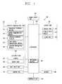
- FIG. 1 is a block diagram of a mobile terminal according to an embodiment of the present invention.
- the mobile terminal 100 includes a wireless communication unit 110, an A/V (Audio/Video) input unit 120, a user input unit 130, a sensing unit 140, an output unit 150, a memory 160, an interface unit 170, a controller 180, and a power supply unit 190.
- FIG. 1 shows the mobile terminal 100 having various components, but it is understood that implementing all of the illustrated components is not a requirement. The mobile terminal 100 may be implemented by greater or fewer components.
- the wireless communication unit 110 typically includes one or more components allowing radio communication between the mobile terminal 100 and a wireless communication system or a network in which the mobile terminal is located.
- the wireless communication unit may include at least one of a broadcast receiving module 111, a mobile communication module 112, a wireless Internet module 113, a short-range communication module 114, and a location information module 115.
- the broadcast receiving module 111 receives broadcast signals and/or broadcast associated information from an external broadcast management server (or other network entity) via a broadcast channel.
- the broadcast channel may include a satellite channel and/or a terrestrial channel.
- the broadcast management server may be a server that generates and transmits a broadcast signal and/or broadcast associated information or a server that receives a previously generated broadcast signal and/or broadcast associated information and transmits the same to a terminal.
- the broadcast associated information may refer to information associated with a broadcast channel, a broadcast program or a broadcast service provider.
- the broadcast signal may include a TV broadcast signal, a radio broadcast signal, a data broadcast signal, and the like. Also, the broadcast signal may further include a broadcast signal combined with a TV or radio broadcast signal.
- the broadcast associated information may also be provided via a mobile communication network and, in this case, the broadcast associated information may be received by the mobile communication module 112.
- the broadcast signal may exist in various forms. For example, it may exist in the form of an electronic program guide (EPG) of digital multimedia broadcasting (DMB), electronic service guide (ESG) of digital video broadcast-handheld (DVB-H), and the like.
- EPG electronic program guide
- DMB digital multimedia broadcasting
- ESG electronic service guide
- DVB-H digital video broadcast-handheld
- the broadcast receiving module 111 may be configured to receive signals broadcast by using various types of broadcast systems.
- the broadcast receiving module 111 may receive a digital broadcast by using a digital broadcast system such as multimedia broadcasting-terrestrial (DMB-T), digital multimedia broadcasting-satellite (DMB-S), digital video broadcast-handheld (DVB-H), the data broadcasting system known as media forward link only (MediaFLO ® ), integrated services digital broadcast-terrestrial (ISDB-T), etc.
- the broadcast receiving module 111 may be configured to be suitable for every broadcast system that provides a broadcast signal as well as the above-mentioned digital broadcast systems.
- Broadcast signals and/or broadcast-associated information received via the broadcast receiving module 111 may be stored in the memory 160 (or anther type of storage medium).
- the mobile communication module 112 transmits and/or receives radio signals to and/or from at least one of a base station, an external terminal and a server.
- radio signals may include a voice call signal, a video call signal or various types of data according to text and/or multimedia message transmission and/or reception.
- the wireless Internet module 113 supports wireless Internet access for the mobile communication terminal. This module may be internally or externally coupled to the mobile terminal 100.
- a wireless local area network (WLAN), Wi-Fi, wireless broadband (WiBro), world interoperability for microwave access (WiMAX), high speed downlink packet access (HSDPA), and the like may be used.
- the short-range communication module 114 is a module for supporting short range communications.
- Some examples of short-range communication technology include Bluetooth TM , Radio Frequency IDentification (RFID), Infrared Data Association (IrDA), Ultra-WideBand (UWB), ZigBee TM , and the like.
- the location information module 115 is a module for checking or acquiring a location (or position) of the mobile communication terminal.
- the location information module 115 may include a GPS (Global Positioning System) module that receives location information from a plurality of satellites.
- the location information may include coordinate information represented by latitude and longitude values.
- the GPS module may measure an accurate time and distance from three or more satellites, and accurately calculate a current location of the mobile terminal according to trigonometry based on the measured time and distances. A method of acquiring distance and time information from three satellites and performing error correction with a single satellite may be used.
- the GPS module may acquire an accurate time together with three-dimensional speed information as well as the location of the latitude, longitude and altitude values from the location information received from the satellites.
- the GPS module may acquire speed information by real time calculating a current position.
- the A/V input unit 120 is configured to receive an audio or video signal.
- the A/V input unit 120 may include a camera 121 and a microphone 122.
- the camera 121 processes image data of still pictures or video acquired by an image capture device in a video capturing mode or an image capturing mode.
- the processed image frames may be displayed on a display unit 151.
- the image frames processed by the camera 121 may be stored in the memory 160 or transmitted via the wireless communication unit 110. Two or more cameras 121 may be provided according to the configuration of the mobile communication terminal.
- the microphone 122 may receive sounds (audible data) via a microphone in a phone call mode, a recording mode, a voice recognition mode, and the like, and can process such sounds into audio data.
- the processed audio (voice) data may be converted for output into a format transmittable to a mobile communication base station via the mobile communication module 112 in case of the phone call mode.
- the microphone 122 may implement various types of noise canceling (or suppression) algorithms to cancel (or suppress) noise or interference generated in the course of receiving and transmitting audio signals.
- the user input unit 130 may generate key input data from commands entered by a user to control various operations of the mobile communication terminal.
- the user input unit 130 allows the user to enter various types of information, and may include a keypad, a dome switch, a touch pad (e.g., a touch sensitive member that detects changes in resistance, pressure, capacitance, etc. due to being contacted) a jog wheel, a jog switch, and the like.
- a touch pad e.g., a touch sensitive member that detects changes in resistance, pressure, capacitance, etc. due to being contacted
- a jog wheel e.g., a jog wheel
- a jog switch e.g., a jog wheel
- a jog switch e.g., a jog wheel
- the touch pad may form a touch screen.
- the sensing unit 140 detects a current status (or state) of the mobile terminal 100 such as an opened or closed state of the mobile terminal 100, a location of the mobile terminal 100, the presence or absence of a user's touch (contact) with the mobile terminal 100 (e.g., touch inputs), the orientation of the mobile terminal 100, an acceleration or deceleration movement and direction of the mobile terminal 100, etc., and generates commands or signals for controlling the operation of the mobile terminal 100.
- the sensing unit 140 may sense whether the slide phone is opened or closed.
- the sensing unit 140 can detect whether or not the power supply unit 190 supplies power or whether or not the interface unit 170 is coupled with an external device.
- the sensing unit 140 may include a proximity sensor 141.
- the sensing unit 140 includes a geomagnetic sensor configured to calculate a moving direction when a user moves, a gyro sensor configured to calculate a rotation direction, and an acceleration sensor.
- the interface unit 170 serves as an interface by which at least one external device may be connected with the mobile terminal 100.
- the external devices may include wired or wireless headset ports, an external power supply (or battery charger) ports, wired or wireless data ports, memory card ports, ports for connecting a device having an identification module, audio input/output (I/O) ports, video I/O ports, earphone ports, or the like.
- the identification module may be a memory chip that stores various information for authenticating user's authority for using the mobile terminal 100 and may include a user identity module (UIM), a subscriber identity module (SIM) a universal subscriber identity module (USIM), and the like.
- the device having the identification module (referred to as the 'identifying device', hereinafter) may take the form of a smart card. Accordingly, the identifying device may be connected with the terminal 100 via a port or other connection mechanisms.
- the interface unit 170 may be used to receive inputs (e.g., data, information, power, etc.) from an external device and transfer the received inputs to one or more elements within the mobile terminal 100 or may be used to transfer data between the mobile terminal and an external device.
- the interface unit 170 may serve as a conduit to allow power from the cradle to be supplied therethrough to the mobile terminal 100 or may serve as a conduit to allow various command signals inputted from the cradle to be transferred to the mobile terminal therethrough.
- Various command signals or power inputted from the cradle may operate as signals for recognizing when the mobile terminal is properly mounted on the cradle.
- the output unit 150 is configured to provide outputs in a visual, audible, and/or tactile manner (e.g., audio signal, video signal, alarm signal, vibration signal, etc.).
- the output unit 150 may include the display unit 151, an audio output module 152, an alarm unit 153, and the like.
- the display unit 151 may display information processed in the mobile terminal 100. For example, when the mobile terminal 100 is in a phone call mode, the display unit 151 may display a User Interface (UI) or a Graphic User Interface (GUI) associated with a call.
- UI User Interface
- GUI Graphic User Interface
- the display unit 151 may function as both an input device and an output device.
- the display unit 151 may include at least one of a Liquid Crystal Display (LCD), a Thin Film Transistor-LCD (TFT-LCD), an Organic Light Emitting Diode (OLED) display, a flexible display, a three-dimensional (3D) display, or the like. Some of these displays may be configured to be transparent so that outside may be seen therethrough, which may be referred to as a transparent display. A representative example of this transparent display may include a transparent organic light emitting diode (TOLED), etc.
- the mobile terminal 100 may include two or more display units 151.
- the mobile terminal may include both an external display unit (not shown) and an internal display unit (not shown).
- the touch screen may be configured to detect a touch input pressure as well as a touch input location and a touch input area.
- the audio output module 152 may convert and output as sound audio data received from the wireless communication unit 110 or stored in the memory 160 in a call signal reception mode, a call mode, a record mode, a voice recognition mode, a broadcast reception mode, and the like. Also, the audio output module 153 may provide audible outputs related to a particular function performed by the mobile terminal 100 (e.g., a call signal reception sound, a message reception sound, etc.). The audio output module 153 may include a speaker, a buzzer, and so on.
- the alarm unit 153 may provide outputs to inform about the occurrence of an event of the mobile terminal 100. Typical events may include call reception, message reception, key signal inputs, a touch input, etc. In addition to audio or video outputs, the alarm unit 153 may provide outputs in a different manner to inform about the occurrence of an event.
- the video signal or the audio signal may be output via the display unit 151 or the audio output module 153. Accordingly, the display unit 151 or the audio output module 152 may be classified as a part of the alarm unit 153.
- the memory 160 may store a program for the processing and control of the controller 180. Alternatively, the memory 160 may temporarily store input/output data (e.g., phonebook data, messages, still images, video and the like). Also, the memory 160 may store data relating to various patterns of vibrations and audio output upon the touch input on the touch screen.
- input/output data e.g., phonebook data, messages, still images, video and the like.
- the memory 160 may store data relating to various patterns of vibrations and audio output upon the touch input on the touch screen.
- the memory 160 may be implemented using any type of suitable storage medium including a flash memory type, a hard disk type, a multimedia card micro type, a memory card type (e.g., SD or DX memory), Random Access Memory (RAM), Static Random Access Memory (SRAM), Read-Only Memory (ROM), Electrically Erasable Programmable Read-only Memory (EEPROM), Programmable Read-only Memory (PROM), magnetic memory, magnetic disk, optical disk, and the like.
- the mobile terminal 100 may operate a web storage which performs the storage function of the memory 160 on the Internet.
- the controller 180 typically controls the overall operations of the mobile terminal 100. For example, the controller 180 performs the control and processing associated with telephony calls, data communications, video calls, and the like.
- the controller 180 may include a multimedia module 181 which provides multimedia playback.
- the multimedia module 181 may be configured as part of the controller 180 or as a separate component.
- the controller 180 can perform a pattern recognition processing so as to recognize writing or drawing input on the touch screen as text or image.
- the power supply unit 190 serves to supply power to each component by receiving external power or internal power under control of the controller 180.
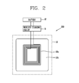
- FIG. 2 is a block diagram of a typical wireless charging module 200.
- the wireless charging module 200 includes a charging receiver module 10 that includes a reception coil 10a and a shield sheet 10b and, in the case of wireless charging, generates induction currents by inductive coupling between the reception coil 10a and a transmission coil (primary coil) provided in a charging unit (e.g., charging pad) (not shown), a wireless charging circuit 11 that controls a wireless charging operation under control of a controller, and a battery 12 that is charged by the induction currents provided through the wireless charging circuit 11.
- a charging receiver module 10 that includes a reception coil 10a and a shield sheet 10b and, in the case of wireless charging, generates induction currents by inductive coupling between the reception coil 10a and a transmission coil (primary coil) provided in a charging unit (e.g., charging pad) (not shown), a wireless charging circuit 11 that controls a wireless charging operation under control of a controller, and a battery 12 that is charged by the induction currents provided through the wireless charging circuit 11.
- the charging receiver module 10 includes the reception coil (secondary coil) 10a that generates induction currents by inductive coupling with the transmission coil (primary coil) provided in the charging unit (e.g., charging pad) and the shield sheet 10b that shields electromagnetic waves generated from the reception coil 10a.
- the reception coil (secondary coil) 10a that generates induction currents by inductive coupling with the transmission coil (primary coil) provided in the charging unit (e.g., charging pad) and the shield sheet 10b that shields electromagnetic waves generated from the reception coil 10a.
- the shield sheet 10b is larger than the reception coil 10a, and the reception coil 10a is attached onto the shield sheet 10b and covered with a battery cover (not shown).
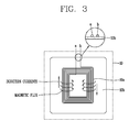
- FIG. 3 is a view showing induction currents and magnetic flux changes which are generated in the charging receiver module 10 in the case of wireless charging.
- eddy currents when the magnetic flux caused by the magnetic field passes through the shield sheet 10b, currents disturbing a change in magnetic field, that is, eddy currents, are generated.
- the eddy currents increase in proportion to the intensity and area of a magnetic field, and cause a temperature rise in the shield sheet 50b.
- the reception coil 10a of the charging receiver module 10 is connected to the wireless charging circuit 11 through coil lines a and b. At this point, the coil lines a and b pass through the shield sheet 10b. Thus, the thickness of the coil lines is added to the thickness of the shield sheet 10b, thus increasing the overall thickness.
- the typical wireless charging module 200 experiences a charging efficiency drop due to a saturation magnetic flux density in the case of wireless charging, and, particularly, the heat generation of the shield sheet 10b caused by eddy currents is emerging as the biggest problem.
- the present invention suggests a method which is capable of improving wireless charging efficiency and eliminating the problem of heat generation caused by eddy currents in the case of wireless charging because a region in which the magnetic flux density is most quickly saturated or a part of the region was clipped off from the shield sheet based on reception coil dimensions and saturation magnetic flux density distribution.
- the present invention provides a shield sheet, a part of which is clipped off based on saturation magnetic flux density distribution in order to facilitate the adjustment of saturation magnetic flux density and reduce eddy currents, rather than providing a shield sheet according to the conventional art having a simple rectangular shape.
- a portion to be clipped off from the shield sheet material includes a region corresponding to the inside of the reception coil when the reception coil is placed on the shield sheet, that is, a center portion of the shield sheet and its periphery where a magnetic flux density is quickly saturated.
- a portion through which the coil lines of the reception coil pass is additionally clipped off.
- the clipping amount and shape are variably determined by the size, shape, material, number of turns, resistance value, and other quality factors of the reception coil and the distribution of a saturation magnetic density.
- the clipping shape can be modified in various ways according to the shape of the reception coil.
- the clipping shape for example, can include a circular shape, an elliptical shape, and other various polygonal shapes.
- reception coils For instance, if two reception coils have different numbers of turns, a larger magnetic flux is generated in the reception coil with more turns even though they have the same size, shape, material, and resistance value. Therefore, to use the reception coil with more turns, the region to be clipped off from the shield sheet needs to be larger.
- the clipping shape may be different from the shape of the reception coil.
- the center portion of the shield sheet and the portion through which the coil lines pass are connected to each other, and the regions of the shield sheet other than the clipped region are cut outward from the center of the shield sheet. At this point, the other regions are not connected to the clipped region, and are cut at regular intervals.
- the reception coil is attached onto the shield sheet to form a wireless charging module, the center portion of the shield sheet and the upper portion through which the coil lines pass are perforated.
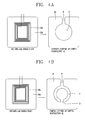
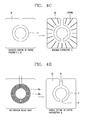
- FIGS. 4A to 4D are a variety of embodiments of a clipped shield sheet.
- FIG. 4A depicts a new shield sheet 20 (type A), which is formed by clipping off a region A, formed by an ellipsoid (or circle) with respect to the center of a rectangular shield sheet 10b, and a region B, through which the coil lines pass, in accordance with the dimensions of the reception coil and the distribution of a magnetic flux density.
- the clipped region A has an elliptical shape, for example, if the reception coil 10a has an elliptical shape, and is smaller than the entire reception coil 10a. That is, the clipped region A is clipped off in a proper size (when viewed from the rear) so that a part of the reception coil 10a is exposed through the clipped region when the reception coil 10a is attached on the shield sheet 20. At this point, the clipped regions A and B are connected to each other.
- the shield sheet 20 shown in FIG. 4A has such a shape that a region including the center is completely clipped off. Therefore, the magnetic flux density decreases near the center in the case of wireless charging. As a result, the magnetic flux density of the shield sheet 20 does not reach a saturation sate, thereby increasing wireless charging efficiency.
- FIG. 4B depicts a new shield sheet 21 (type B), which is formed by clipping off a region C, formed by two ellipsoids (or circles) having different diameters with respect to the center of a rectangular shield sheet 10b, and a region B, through which the coil lines pass, in accordance with the shape of the reception coil 10a.
- the shield sheet of type B has such a shape that a region not including the center is clipped off.
- the region C is not completely clipped off, but is discontinuously clipped off so that the remaining center portion(the portion including the center) is connected to the shield sheet 21.
- the discontinuous region D may be formed at, but not limited to, the bottom, and may be formed at the top, left, or right. Moreover, at least one discontinuous region D may be formed.
- the shield sheet 21 shown in FIG. 4B has such a shape that the center portion remains and the periphery thereof is partially clipped off. Therefore, the magnetic flux density is saturated near the center in the case of wireless charging, but the portion where the coils are placed is not saturated, thereby increasing wireless charging efficiency.
- FIG. 4C depicts a shield sheet 22 (type C), which is formed by diagonally cutting the unclipped portion toward the clipped region C on the shield sheet 21 shown in FIG. 4B .
- the width, number, and intervals of cuts can be set by the user.
- the performance of the shield sheet 22 (type C) is similar to the performance of the shield sheet 21 (type B), it has flaws or cuts, which are not formed in the shield sheet 21. Thus, the eddy current generation area is decreased, and this causes less heat generation.
- FIGS. 4A to 4C depict the shield sheet 21 clipped off in a circular shape with respect to the elliptical reception coil 10a, but the present invention is not limited thereto and the reception coil 10a and the shield sheet 21 may have the same shape as shown in FIG. 4D , that is, the shield sheet 21 may be clipped off in a circular shape with respect to the circular reception coil 10a.
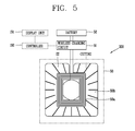
- FIG. 5 is a block diagram of a wireless charging module 300 including a shield sheet according to an embodiment of the present invention.
- the wireless charging module 300 shown in FIG. 5 has the same components as FIG. 3 , except for a charging receiver module 50, though different reference numerals are used.
- the charging receiver module 50 includes a reception coil 50a that, in the case of wireless charging, generates induction currents by inductive coupling with a transmission coil (primary coil) provided in a charging unit (e.g., charging pad) and a shield sheet 50b that shields electromagnetic waves generated from the reception coil 50a when the reception coil 50a is placed, with the center portion being clipped off in a predetermined shape based on saturation magnetic density distribution.
- the shield sheet 50b is one of the types A through C shown in FIGS. 4a through 4c .
- FIG. 5 illustrates an example of the shield sheet 50b of type C.
- the induction currents generated from the charging receiver module 50 is charged in a battery 52 through a wireless charging circuit 51.
- the battery 52 corresponds to the power supply unit 190 of FIG. 1 .
- the wireless charging circuit 51 detects a charged state of the battery under control of the controller 180 to control a wireless charging operation, and the detected charged state of the battery 52 is displayed on the display unit 151 through the controller 180.
- the saturation magnetic flux density of the shield sheet 50b is adjusted in accordance with a cutting position and shape. Accordingly, when induction currents are generated by inductive coupling between the transmission coil (primary coil) provided in the charging unit (e.g., charging pad) and the reception coil, it may be further absorbed into the shield sheet 50b of a magnetic flux generated by electromagnetic induction. Consequently, the penetration of the coils of the magnetic flux becomes deeper, compared to the conventional art, and this leads to an increase in wireless charging efficiency on the whole.
- the shield sheet 50b is used to constitute the charging receiver module 50, eddy currents generated in the shield sheet 50b decrease in accordance with a cutting position and shape, thereby reducing heat generation, compared to the conventional art.
- FIG. 6 is a view showing the arrangement positions of the coil lines a and b of the reception coil 50a when the shield sheet 50b is used to constitute the charging receiver module 50.
- the reception coil 50a is attached onto the shield sheet 50b when used to constitute the charging receiver module 50.
- the coil lines a and b of the reception coil 50a are placed within the clipped region B, so the thickness of the coil lines a and b can be eliminated.
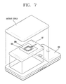
- FIG. 7 is a view showing an example of coupling of a charging receiver module to a mobile terminal.
- the charging receiver module 50 is connected to the battery 52 through the wireless charging unit 51 positioned on the rear surface of the mobile terminal.
- An input end of the wireless charging circuit 51 is connected to the coil lines a and b of the reception coil 50a, and an output end thereof is coupled to the battery 52.
- the wireless charging circuit 51 has a charging control function for controlling charging or discharging by detecting the state of the battery 52 under control of the controller 180.
- a battery cover is placed on top of the charging receiver module 50.
- the charging unit e.g., charging pad
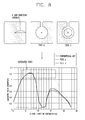
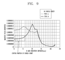
- FIGS. 8 and 9 are graphs showing simulation results for shield sheet types when the charging receiver module 50 is configured to perform wireless charging.
- FIG. 8 is a graph showing the distribution of magnetic flux density of a shield sheet according to shield sheet types.
- the magnetic flux density of a portion extending from the center of the shield sheet to a coil placement part gets saturated (about 1.2T) during actual wireless charging.
- the wireless charging efficiency is lowered, and eddy currents are generated, thereby increasing heat generation.
- the magnetic flux density is quite low (about 0.1T) during actual wireless charging because the center portion of the shield sheet was clipped off, and the magnetic flux density increases toward the outside to reach about 0.63T.
- the shield sheet of type B of the present invention is used to constitute the charging receiver module 50, the magnetic flux density is saturated (about 1.2T) during actual wireless charging because the center portion of the shield sheet was not clipped off, and the magnetic flux density is abruptly lowered due to the clipped region and increases again toward the outside to reach about 0.6T. That is, the saturation of the shield sheet at the reception coil portion was lowered by about 50% compared to the conventional art.
- FIG. 9 is a graph showing the distribution of shielding effect according to shield sheet types.
- the intensity T of a magnetic field obtained when no shield sheet is used is almost similar to the intensity T of a magnetic field obtained when the shield sheet of type A of the present invention.
- the intensity T of a magnetic field at the center obtained when the shield sheet of type B of the present invention is used becomes lower than those obtained when the shield sheets of the conventional art and type A are used, whereby it can be seen that the shielding effect is improved. Accordingly, in the case that the shield sheet of type B or C of the present invention is used to constitute the charging receiver module 50, charging efficiency can be increased, and the problem of heat generation caused by eddy currents can be effectively solved without lowering the shielding effect.
- the present invention can improve wireless charging efficiency and eliminate the problem of heat generation of a shield sheet, because a region in which the magnetic flux density is most quickly saturated or a part of the region was clipped off from the shield sheet based on a magnetic flux density distribution when configuring a wireless charging module, and the saturation magnetic flux density distribution of the shield sheet and the generation of eddy currents are adjusted when performing wireless charging by induction currents generated by electromagnetic induction between a transmission coil of a charging unit and a reception coil of the wireless charging module.
- the above-described method can be implemented as a computer readable code on a medium recording a program.
- the computer readable medium includes all kinds of storage devices for storing data readable by a computer system. Examples of the computer readable medium include ROM, RAM, CD-ROMs, magnetic tapes, floppy disks, optical data storage devices, and so on, and may also be implemented in the form of carrier waves, such as transmission over the Internet.
- the computer may include a controller of a terminal.
- the above-described mobile terminal is not limited to the configuration and method of the embodiments described as above, but the embodiments may be configured by selectively combining all the embodiments or some of the embodiments so that various modifications can be made.
Landscapes
- Engineering & Computer Science (AREA)
- Power Engineering (AREA)
- Computer Networks & Wireless Communication (AREA)
- Physics & Mathematics (AREA)
- Electromagnetism (AREA)
- Signal Processing (AREA)
- Charge And Discharge Circuits For Batteries Or The Like (AREA)
- Telephone Set Structure (AREA)
Abstract
Description
- The present disclosure relates to a mobile terminal which can improve wireless charging efficiency and reduce heat generation by adjusting the saturation magnetic flux density and eddy currents of a shield sheet, and particularly, to a wireless charging module therefor.
- Recently, mobile terminals allowing users to receive broadcast or multicast signals to view video or television programs have created the demand for higher-capacity batteries. However, batteries having a satisfactory level of capacity have not been developed yet despite continuing research. As a result, unless a charging operation is performed by determining a proper charging time and method based on a residual battery amount, mobile terminals may often fail to allow user to view video or television programs.
- Accordingly, a variety of charging apparatuses and methods for making it easy to charge a battery of a mobile terminal are being developed.
- In general, in order to charge a battery, there is a need for a charging unit (or charging body or charging apparatus) connected to a general power source to supply electric energy to a battery of a mobile terminal. Separate contact terminals are respectively provided to outsides of the charging unit and the battery so that the battery can be charged by connecting both contact terminals.
- However, the contact terminals provided to outsides of the charging unit and the battery are not desirable in terms of appearance. Moreover, if they are exposed to moisture, the charged energy may be lost, and a charging operation may not be properly performed due to an inferior contact status. Further, the user needs to always carry the charging unit in order to charge the battery.
- Therefore, to solve the above-mentioned problems, there has been developed a method that allows easy charging in a wireless (or contactless) manner without including separate contact terminals respectively in the charging unit and the battery, which is used in some fields of applications.
- Known examples of the conventional non-contact charging method include a wireless charging method using inductive coupling and a wireless charging method using capacity coupling. Of the two methods, the wireless charging method using inductive coupling is a method in which a charging unit (e.g., charging pad) is equipped with a primary coil (transmission coil) and a charging target such as a terminal is equipped with a secondary coil (reception coil), and a current generated by the inductive coupling between the primary and secondary coils when the terminal approaches the charging unit is converted into energy to charge a battery.
- The secondary coil has an elliptical shape and is provided on the rear surface of the mobile terminal, i.e., on the inside of a battery case, a rectangular-shaped shield sheet for shielding a magnetic flux generated by the secondary coil by electromagnetic induction is positioned under the secondary coil, and a battery cover is placed on top of the secondary coil. That is, if the battery cover is closed, the shield sheet, the secondary coil, and the battery cover are arranged in order from the inside to the outside.
- In the non-contact charging method using inductive coupling, however, the secondary coil causes a magnetic flux density to quickly reach a saturated state in the case of wireless charging because the shield sheet is formed in a simple rectangular shape, and the magnetic flux generates eddy currents in the shield sheet to disturb a change in magnetic field.
- Therefore, unsaturated magnetic fields of the secondary coil (reception coil) are all lost after the magnetic flux density reaches the saturated state, whereby wireless charging efficiency is reduced, and the temperature of the shield sheet rises due to the eddy currents.
- Therefore, an aspect of the detailed description is to provide a mobile terminal which can increase charging efficiency and reduce heat generation in the case of wireless charging using inductive coupling and a wireless charging module therefor.
- Another aspect of the detailed description is to provide a mobile terminal which can reduce heat generation caused by eddy currents in the case of wireless charging using inductive coupling and a wireless charging module therefor.
- To achieve these and other advantages and in accordance with the purpose of this specification, as embodied and broadly described herein, a mobile terminal according to an embodiment of the present invention includes: a terminal body configured to allow a touch input; a display unit for displaying a saturated state of a battery; a wireless charging module that comprises a reception coil and a shield sheet, a part of which is clipped off based on saturation magnetic flux density distribution, and charges the battery by induction currents generated by electromagnetic induction between a transmission coil of a charging unit and the reception coil in the case of wireless charging; and a controller for controlling a charging operation of the wireless charging module.
- The clipped region comprises a region in which the magnetic flux density is most quickly saturated when wireless charging is performed because the reception coil is placed on the shield sheet and a portion through which coil lines of the reception coil pass.
- The size and shape of the clipped region is determined by the size, shape, material, number of turns, and resistance value of the reception coil and the distribution of a saturation magnetic density generated by the reception coil.
- The regions of the shield sheet other than the clipped region are regularly cut outward from the center of the shield sheet, and the cut regions are not connected to the clipped region at the center portion.
- The shield sheet is any one of a shield sheet from which a first region comprising the center is clipped off, a shield sheet from which a second region not comprising the center is clipped off, and a shield sheet diagonally cut at the regions other than the second region.
- The shapes of the first and second regions comprise a circular shape, an elliptical shape, and a polygonal shape corresponding to the shape of the reception coil, and the second region is discontinuously clipped off.
- The wireless charging module in the mobile terminal includes: a charging receiver module that generates induction currents by electromagnetic induction between the transmission coil and the reception coil in the case of contactless charging; a battery that charges the induction currents generated from the charging receiver module; and a wireless charging circuit that controls wireless charging of the battery under control of a controller between the charging receiver module and the battery.
- To achieve these and other advantages and in accordance with the purpose of this specification, as embodied and broadly described herein, a wireless charging module according to an embodiment of the present invention includes: a battery for charging induction currents; a wireless charging module that comprises a reception coil and a shield sheet, a part of which is clipped off based on saturation magnetic flux density distribution, and charges the battery by induction currents generated by electromagnetic induction between a transmission coil of a charging unit and the reception coil in the case of wireless charging; and a wireless charging circuit that controls wireless charging of the battery between the charging receiver module and the battery.
- The clipped region comprises a region in which the magnetic flux density is most quickly saturated when wireless charging is performed because the reception coil is placed on the shield sheet and a portion through which coil lines of the reception coil pass.
- The size and shape of the clipped region is determined by the size, shape, material, number of turns, and resistance value of the reception coil and the distribution of a saturation magnetic density generated by the reception coil.
- The regions of the shield sheet other than the clipped region are regularly cut outward from the center of the shield sheet, and the cut regions are not connected to the clipped region at the center portion.
- The shield sheet is any one of a shield sheet from which a first region comprising the center is clipped off, a shield sheet from which a second region not comprising the center is clipped off, and a shield sheet diagonally cut at the regions other than the second region. The shapes of the first and second regions comprise a circular shape, an elliptical shape, and a polygonal shape corresponding to the shape of the reception coil, and the second region is discontinuously clipped off.
- Further scope of applicability of the present application will become more apparent from the detailed description given hereinafter. However, it should be understood that the detailed description and specific examples, while indicating preferred embodiments of the invention, are given by way of illustration only, since various changes and modifications within the spirit and scope of the invention will become apparent to those skilled in the art from the detailed description.
- The accompanying drawings, which are included to provide a further understanding of the invention and are incorporated in and constitute a part of this specification, illustrate exemplary embodiments and together with the description serve to explain the principles of the invention.
- In the drawings:
-
FIG. 1 is a block diagram of a mobile terminal associated with an embodiment of the present invention. -
FIG. 2 is a block diagram of a typical wireless charging module; -
FIG. 3 is a view showing induction currents and magnetic flux changes which are generated in a charging receiver module in the case of wireless charging; -
FIGS. 4A to 4D are a variety of embodiments of a clipped shield sheet according to the present invention; -
FIG. 5 is a block diagram of a wireless charging module including a shield sheet according to an embodiment of the present invention; -
FIG. 6 is a view showing the arrangement positions of coil lines of a reception coil when a shield sheet is used to constitute a charging receiver module according to the present invention; -
FIG. 7 is a view showing an example of coupling of a charging receiver module to a mobile terminal. -
FIG. 8 is a graph showing the distribution of magnetic flux density of a shield sheet according to shield sheet types; and -
FIG. 9 is a graph showing the distribution of shielding effect according to shield sheet types. - Description will now be given in detail of the exemplary embodiments, with reference to the accompanying drawings. For the sake of brief description with reference to the drawings, the same or equivalent components will be provided with the same reference numbers, and description thereof will not be repeated.
- Hereinafter, a mobile terminal according to the present invention will be explained in more detail with reference to the attached drawings. The suffixes attached to components of the wireless speaker, such as 'module' and 'unit or portion' were used for facilitation of the detailed description of the present invention. Therefore, the suffixes do not have different meanings from each other.
- A terminal may be implemented in various types. For instance, the terminal in the present description includes a mobile terminal such as a portable phone, a smart phone, a notebook computer, a digital broadcasting terminal, Personal Digital Assistants (PDA), Portable Multimedia Player (PMP), a navigation system, and a fixed terminal such as a digital TV, a desktop computer, etc. It is assumed that the terminal of the present invention is a mobile terminal. However, it will be obvious to those skilled in the art that the present invention may be also applicable to the fixed terminal, except for specific configurations for mobility.
-
FIG. 1 is a block diagram of a mobile terminal according to an embodiment of the present invention. - As shown in
FIG. 1 , themobile terminal 100 includes awireless communication unit 110, an A/V (Audio/Video)input unit 120, auser input unit 130, asensing unit 140, anoutput unit 150, amemory 160, aninterface unit 170, acontroller 180, and apower supply unit 190.FIG. 1 shows themobile terminal 100 having various components, but it is understood that implementing all of the illustrated components is not a requirement. Themobile terminal 100 may be implemented by greater or fewer components. - The
wireless communication unit 110 typically includes one or more components allowing radio communication between themobile terminal 100 and a wireless communication system or a network in which the mobile terminal is located. For example, the wireless communication unit may include at least one of abroadcast receiving module 111, amobile communication module 112, awireless Internet module 113, a short-range communication module 114, and alocation information module 115. - The
broadcast receiving module 111 receives broadcast signals and/or broadcast associated information from an external broadcast management server (or other network entity) via a broadcast channel. The broadcast channel may include a satellite channel and/or a terrestrial channel. The broadcast management server may be a server that generates and transmits a broadcast signal and/or broadcast associated information or a server that receives a previously generated broadcast signal and/or broadcast associated information and transmits the same to a terminal. The broadcast associated information may refer to information associated with a broadcast channel, a broadcast program or a broadcast service provider. The broadcast signal may include a TV broadcast signal, a radio broadcast signal, a data broadcast signal, and the like. Also, the broadcast signal may further include a broadcast signal combined with a TV or radio broadcast signal. - The broadcast associated information may also be provided via a mobile communication network and, in this case, the broadcast associated information may be received by the
mobile communication module 112. - The broadcast signal may exist in various forms. For example, it may exist in the form of an electronic program guide (EPG) of digital multimedia broadcasting (DMB), electronic service guide (ESG) of digital video broadcast-handheld (DVB-H), and the like.
- The
broadcast receiving module 111 may be configured to receive signals broadcast by using various types of broadcast systems. In particular, thebroadcast receiving module 111 may receive a digital broadcast by using a digital broadcast system such as multimedia broadcasting-terrestrial (DMB-T), digital multimedia broadcasting-satellite (DMB-S), digital video broadcast-handheld (DVB-H), the data broadcasting system known as media forward link only (MediaFLO®), integrated services digital broadcast-terrestrial (ISDB-T), etc. Thebroadcast receiving module 111 may be configured to be suitable for every broadcast system that provides a broadcast signal as well as the above-mentioned digital broadcast systems. - Broadcast signals and/or broadcast-associated information received via the
broadcast receiving module 111 may be stored in the memory 160 (or anther type of storage medium). - The
mobile communication module 112 transmits and/or receives radio signals to and/or from at least one of a base station, an external terminal and a server. Such radio signals may include a voice call signal, a video call signal or various types of data according to text and/or multimedia message transmission and/or reception. - The
wireless Internet module 113 supports wireless Internet access for the mobile communication terminal. This module may be internally or externally coupled to themobile terminal 100. Here, as the wireless Internet technique, a wireless local area network (WLAN), Wi-Fi, wireless broadband (WiBro), world interoperability for microwave access (WiMAX), high speed downlink packet access (HSDPA), and the like, may be used. - The short-
range communication module 114 is a module for supporting short range communications. Some examples of short-range communication technology include Bluetooth™, Radio Frequency IDentification (RFID), Infrared Data Association (IrDA), Ultra-WideBand (UWB), ZigBee™, and the like. - The
location information module 115 is a module for checking or acquiring a location (or position) of the mobile communication terminal. For example, thelocation information module 115 may include a GPS (Global Positioning System) module that receives location information from a plurality of satellites. Here, the location information may include coordinate information represented by latitude and longitude values. For example, the GPS module may measure an accurate time and distance from three or more satellites, and accurately calculate a current location of the mobile terminal according to trigonometry based on the measured time and distances. A method of acquiring distance and time information from three satellites and performing error correction with a single satellite may be used. In particular, the GPS module may acquire an accurate time together with three-dimensional speed information as well as the location of the latitude, longitude and altitude values from the location information received from the satellites. Furthermore the GPS module may acquire speed information by real time calculating a current position. - The A/
V input unit 120 is configured to receive an audio or video signal. The A/V input unit 120 may include acamera 121 and amicrophone 122. Thecamera 121 processes image data of still pictures or video acquired by an image capture device in a video capturing mode or an image capturing mode. The processed image frames may be displayed on adisplay unit 151. - The image frames processed by the
camera 121 may be stored in thememory 160 or transmitted via thewireless communication unit 110. Two ormore cameras 121 may be provided according to the configuration of the mobile communication terminal. - The
microphone 122 may receive sounds (audible data) via a microphone in a phone call mode, a recording mode, a voice recognition mode, and the like, and can process such sounds into audio data. The processed audio (voice) data may be converted for output into a format transmittable to a mobile communication base station via themobile communication module 112 in case of the phone call mode. Themicrophone 122 may implement various types of noise canceling (or suppression) algorithms to cancel (or suppress) noise or interference generated in the course of receiving and transmitting audio signals. - The
user input unit 130 may generate key input data from commands entered by a user to control various operations of the mobile communication terminal. Theuser input unit 130 allows the user to enter various types of information, and may include a keypad, a dome switch, a touch pad (e.g., a touch sensitive member that detects changes in resistance, pressure, capacitance, etc. due to being contacted) a jog wheel, a jog switch, and the like. In particular, when the touch pad is overlaid on thedisplay unit 151 in a layered manner, it may form a touch screen. - The
sensing unit 140 detects a current status (or state) of themobile terminal 100 such as an opened or closed state of themobile terminal 100, a location of themobile terminal 100, the presence or absence of a user's touch (contact) with the mobile terminal 100 (e.g., touch inputs), the orientation of themobile terminal 100, an acceleration or deceleration movement and direction of themobile terminal 100, etc., and generates commands or signals for controlling the operation of themobile terminal 100. For example, when themobile terminal 100 is implemented as a slide type mobile phone, thesensing unit 140 may sense whether the slide phone is opened or closed. In addition, thesensing unit 140 can detect whether or not thepower supply unit 190 supplies power or whether or not theinterface unit 170 is coupled with an external device. Thesensing unit 140 may include a proximity sensor 141. - The
sensing unit 140 includes a geomagnetic sensor configured to calculate a moving direction when a user moves, a gyro sensor configured to calculate a rotation direction, and an acceleration sensor. - The
interface unit 170 serves as an interface by which at least one external device may be connected with themobile terminal 100. For example, the external devices may include wired or wireless headset ports, an external power supply (or battery charger) ports, wired or wireless data ports, memory card ports, ports for connecting a device having an identification module, audio input/output (I/O) ports, video I/O ports, earphone ports, or the like. - Here, the identification module may be a memory chip that stores various information for authenticating user's authority for using the
mobile terminal 100 and may include a user identity module (UIM), a subscriber identity module (SIM) a universal subscriber identity module (USIM), and the like. In addition, the device having the identification module (referred to as the 'identifying device', hereinafter) may take the form of a smart card. Accordingly, the identifying device may be connected with the terminal 100 via a port or other connection mechanisms. Theinterface unit 170 may be used to receive inputs (e.g., data, information, power, etc.) from an external device and transfer the received inputs to one or more elements within themobile terminal 100 or may be used to transfer data between the mobile terminal and an external device. - When the
mobile terminal 100 is connected with an external cradle, theinterface unit 170 may serve as a conduit to allow power from the cradle to be supplied therethrough to themobile terminal 100 or may serve as a conduit to allow various command signals inputted from the cradle to be transferred to the mobile terminal therethrough. Various command signals or power inputted from the cradle may operate as signals for recognizing when the mobile terminal is properly mounted on the cradle. - The
output unit 150 is configured to provide outputs in a visual, audible, and/or tactile manner (e.g., audio signal, video signal, alarm signal, vibration signal, etc.). Theoutput unit 150 may include thedisplay unit 151, anaudio output module 152, analarm unit 153, and the like. - The
display unit 151 may display information processed in themobile terminal 100. For example, when themobile terminal 100 is in a phone call mode, thedisplay unit 151 may display a User Interface (UI) or a Graphic User Interface (GUI) associated with a call. - When the
display unit 151 and the touch pad are overlaid in a layered manner to form a touch screen, thedisplay unit 151 may function as both an input device and an output device. Thedisplay unit 151 may include at least one of a Liquid Crystal Display (LCD), a Thin Film Transistor-LCD (TFT-LCD), an Organic Light Emitting Diode (OLED) display, a flexible display, a three-dimensional (3D) display, or the like. Some of these displays may be configured to be transparent so that outside may be seen therethrough, which may be referred to as a transparent display. A representative example of this transparent display may include a transparent organic light emitting diode (TOLED), etc. Themobile terminal 100 may include two ormore display units 151. For example, the mobile terminal may include both an external display unit (not shown) and an internal display unit (not shown). The touch screen may be configured to detect a touch input pressure as well as a touch input location and a touch input area. - The
audio output module 152 may convert and output as sound audio data received from thewireless communication unit 110 or stored in thememory 160 in a call signal reception mode, a call mode, a record mode, a voice recognition mode, a broadcast reception mode, and the like. Also, theaudio output module 153 may provide audible outputs related to a particular function performed by the mobile terminal 100 (e.g., a call signal reception sound, a message reception sound, etc.). Theaudio output module 153 may include a speaker, a buzzer, and so on. - The
alarm unit 153 may provide outputs to inform about the occurrence of an event of themobile terminal 100. Typical events may include call reception, message reception, key signal inputs, a touch input, etc. In addition to audio or video outputs, thealarm unit 153 may provide outputs in a different manner to inform about the occurrence of an event. The video signal or the audio signal may be output via thedisplay unit 151 or theaudio output module 153. Accordingly, thedisplay unit 151 or theaudio output module 152 may be classified as a part of thealarm unit 153. - The
memory 160 may store a program for the processing and control of thecontroller 180. Alternatively, thememory 160 may temporarily store input/output data (e.g., phonebook data, messages, still images, video and the like). Also, thememory 160 may store data relating to various patterns of vibrations and audio output upon the touch input on the touch screen. - The
memory 160 may be implemented using any type of suitable storage medium including a flash memory type, a hard disk type, a multimedia card micro type, a memory card type (e.g., SD or DX memory), Random Access Memory (RAM), Static Random Access Memory (SRAM), Read-Only Memory (ROM), Electrically Erasable Programmable Read-only Memory (EEPROM), Programmable Read-only Memory (PROM), magnetic memory, magnetic disk, optical disk, and the like. Also, themobile terminal 100 may operate a web storage which performs the storage function of thememory 160 on the Internet. - The
controller 180 typically controls the overall operations of themobile terminal 100. For example, thecontroller 180 performs the control and processing associated with telephony calls, data communications, video calls, and the like. Thecontroller 180 may include amultimedia module 181 which provides multimedia playback. Themultimedia module 181 may be configured as part of thecontroller 180 or as a separate component. - The
controller 180 can perform a pattern recognition processing so as to recognize writing or drawing input on the touch screen as text or image. - The
power supply unit 190 serves to supply power to each component by receiving external power or internal power under control of thecontroller 180. - Various embodiments described herein may be implemented in a computer-readable medium using, for example, software, hardware, or some combination thereof.
-
FIG. 2 is a block diagram of a typicalwireless charging module 200. - As shown therein, the
wireless charging module 200 includes a chargingreceiver module 10 that includes areception coil 10a and ashield sheet 10b and, in the case of wireless charging, generates induction currents by inductive coupling between thereception coil 10a and a transmission coil (primary coil) provided in a charging unit (e.g., charging pad) (not shown), awireless charging circuit 11 that controls a wireless charging operation under control of a controller, and abattery 12 that is charged by the induction currents provided through thewireless charging circuit 11. - The charging
receiver module 10 includes the reception coil (secondary coil) 10a that generates induction currents by inductive coupling with the transmission coil (primary coil) provided in the charging unit (e.g., charging pad) and theshield sheet 10b that shields electromagnetic waves generated from thereception coil 10a. - The
shield sheet 10b is larger than thereception coil 10a, and thereception coil 10a is attached onto theshield sheet 10b and covered with a battery cover (not shown). -
FIG. 3 is a view showing induction currents and magnetic flux changes which are generated in the chargingreceiver module 10 in the case of wireless charging. - As shown in
FIG. 3 , when a mobile terminal is placed on a charging pad, a magnetic field is generated by inductive coupling between the transmission coil (not shown) andreception coil 10a of the charging pad to cause induction currents to flow through thereception coil 10a. At this point, when the reception coil is placed at a center portion of theshield sheet 50a, the magnetic flux density of a region of the shield sheet corresponding to the inside of the reception coil increases, and hence the magnetic flux density of theshield sheet 50a where thereception coil 10a is placed also quickly reaches a saturated state. - If the magnetic flux density quickly reaches a saturated state, this means that the magnetic flux quickly approaches a maximum value, which implies that there is less room for absorbing magnetic flux.
- Therefore, unsaturated magnetic fields are all lost after the magnetic flux density reaches the saturated state, thereby causing a reduction in wireless charging efficiency and, especially, an increase in heat generation caused by the magnetic field loss.
- Moreover, when the magnetic flux caused by the magnetic field passes through the
shield sheet 10b, currents disturbing a change in magnetic field, that is, eddy currents, are generated. The eddy currents increase in proportion to the intensity and area of a magnetic field, and cause a temperature rise in theshield sheet 50b. - Further, the
reception coil 10a of the chargingreceiver module 10 is connected to thewireless charging circuit 11 through coil lines a and b. At this point, the coil lines a and b pass through theshield sheet 10b. Thus, the thickness of the coil lines is added to the thickness of theshield sheet 10b, thus increasing the overall thickness. - As such, the typical
wireless charging module 200 experiences a charging efficiency drop due to a saturation magnetic flux density in the case of wireless charging, and, particularly, the heat generation of theshield sheet 10b caused by eddy currents is emerging as the biggest problem. - Accordingly, in order to solve the problems occurring in the typical wireless charging module, the present invention suggests a method which is capable of improving wireless charging efficiency and eliminating the problem of heat generation caused by eddy currents in the case of wireless charging because a region in which the magnetic flux density is most quickly saturated or a part of the region was clipped off from the shield sheet based on reception coil dimensions and saturation magnetic flux density distribution.
- The present invention provides a shield sheet, a part of which is clipped off based on saturation magnetic flux density distribution in order to facilitate the adjustment of saturation magnetic flux density and reduce eddy currents, rather than providing a shield sheet according to the conventional art having a simple rectangular shape.
- Provided that a shield sheet material has a rectangular shape, a portion to be clipped off from the shield sheet material includes a region corresponding to the inside of the reception coil when the reception coil is placed on the shield sheet, that is, a center portion of the shield sheet and its periphery where a magnetic flux density is quickly saturated. In order to reduce the thickness, a portion through which the coil lines of the reception coil pass is additionally clipped off.
- The clipping amount and shape are variably determined by the size, shape, material, number of turns, resistance value, and other quality factors of the reception coil and the distribution of a saturation magnetic density. Especially, the clipping shape can be modified in various ways according to the shape of the reception coil. The clipping shape, for example, can include a circular shape, an elliptical shape, and other various polygonal shapes.
- For instance, if two reception coils have different numbers of turns, a larger magnetic flux is generated in the reception coil with more turns even though they have the same size, shape, material, and resistance value. Therefore, to use the reception coil with more turns, the region to be clipped off from the shield sheet needs to be larger.
- In another embodiment, the clipping shape may be different from the shape of the reception coil.
- The center portion of the shield sheet and the portion through which the coil lines pass are connected to each other, and the regions of the shield sheet other than the clipped region are cut outward from the center of the shield sheet. At this point, the other regions are not connected to the clipped region, and are cut at regular intervals.
- Accordingly, if the reception coil is attached onto the shield sheet to form a wireless charging module, the center portion of the shield sheet and the upper portion through which the coil lines pass are perforated.
-
FIGS. 4A to 4D are a variety of embodiments of a clipped shield sheet. -
FIG. 4A depicts a new shield sheet 20 (type A), which is formed by clipping off a region A, formed by an ellipsoid (or circle) with respect to the center of arectangular shield sheet 10b, and a region B, through which the coil lines pass, in accordance with the dimensions of the reception coil and the distribution of a magnetic flux density. - The clipped region A has an elliptical shape, for example, if the
reception coil 10a has an elliptical shape, and is smaller than theentire reception coil 10a. That is, the clipped region A is clipped off in a proper size (when viewed from the rear) so that a part of thereception coil 10a is exposed through the clipped region when thereception coil 10a is attached on theshield sheet 20. At this point, the clipped regions A and B are connected to each other. - The
shield sheet 20 shown inFIG. 4A has such a shape that a region including the center is completely clipped off. Therefore, the magnetic flux density decreases near the center in the case of wireless charging. As a result, the magnetic flux density of theshield sheet 20 does not reach a saturation sate, thereby increasing wireless charging efficiency. -
FIG. 4B depicts a new shield sheet 21 (type B), which is formed by clipping off a region C, formed by two ellipsoids (or circles) having different diameters with respect to the center of arectangular shield sheet 10b, and a region B, through which the coil lines pass, in accordance with the shape of thereception coil 10a. - That is, the shield sheet of type B has such a shape that a region not including the center is clipped off. At this point, the region C is not completely clipped off, but is discontinuously clipped off so that the remaining center portion(the portion including the center) is connected to the
shield sheet 21. The discontinuous region D may be formed at, but not limited to, the bottom, and may be formed at the top, left, or right. Moreover, at least one discontinuous region D may be formed. - The
shield sheet 21 shown inFIG. 4B has such a shape that the center portion remains and the periphery thereof is partially clipped off. Therefore, the magnetic flux density is saturated near the center in the case of wireless charging, but the portion where the coils are placed is not saturated, thereby increasing wireless charging efficiency. -
FIG. 4C depicts a shield sheet 22 (type C), which is formed by diagonally cutting the unclipped portion toward the clipped region C on theshield sheet 21 shown inFIG. 4B . At this point, the width, number, and intervals of cuts can be set by the user. - Although the performance of the shield sheet 22 (type C) is similar to the performance of the shield sheet 21 (type B), it has flaws or cuts, which are not formed in the
shield sheet 21. Thus, the eddy current generation area is decreased, and this causes less heat generation. -
FIGS. 4A to 4C depict theshield sheet 21 clipped off in a circular shape with respect to theelliptical reception coil 10a, but the present invention is not limited thereto and thereception coil 10a and theshield sheet 21 may have the same shape as shown inFIG. 4D , that is, theshield sheet 21 may be clipped off in a circular shape with respect to thecircular reception coil 10a. -
FIG. 5 is a block diagram of awireless charging module 300 including a shield sheet according to an embodiment of the present invention. Thewireless charging module 300 shown inFIG. 5 has the same components asFIG. 3 , except for a chargingreceiver module 50, though different reference numerals are used. - As shown in
FIG. 5 , the chargingreceiver module 50 includes areception coil 50a that, in the case of wireless charging, generates induction currents by inductive coupling with a transmission coil (primary coil) provided in a charging unit (e.g., charging pad) and ashield sheet 50b that shields electromagnetic waves generated from thereception coil 50a when thereception coil 50a is placed, with the center portion being clipped off in a predetermined shape based on saturation magnetic density distribution. Theshield sheet 50b is one of the types A through C shown inFIGS. 4a through 4c .FIG. 5 illustrates an example of theshield sheet 50b of type C. - The induction currents generated from the charging
receiver module 50 is charged in abattery 52 through awireless charging circuit 51. Thebattery 52 corresponds to thepower supply unit 190 ofFIG. 1 . - The
wireless charging circuit 51 detects a charged state of the battery under control of thecontroller 180 to control a wireless charging operation, and the detected charged state of thebattery 52 is displayed on thedisplay unit 151 through thecontroller 180. - If the
shield sheet 50b is used to constitute the chargingreceiver module 50, the saturation magnetic flux density of theshield sheet 50b is adjusted in accordance with a cutting position and shape. Accordingly, when induction currents are generated by inductive coupling between the transmission coil (primary coil) provided in the charging unit (e.g., charging pad) and the reception coil, it may be further absorbed into theshield sheet 50b of a magnetic flux generated by electromagnetic induction. Consequently, the penetration of the coils of the magnetic flux becomes deeper, compared to the conventional art, and this leads to an increase in wireless charging efficiency on the whole. - Moreover, if the
shield sheet 50b is used to constitute the chargingreceiver module 50, eddy currents generated in theshield sheet 50b decrease in accordance with a cutting position and shape, thereby reducing heat generation, compared to the conventional art. -
FIG. 6 is a view showing the arrangement positions of the coil lines a and b of thereception coil 50a when theshield sheet 50b is used to constitute the chargingreceiver module 50. - As shown in
FIG. 6 , thereception coil 50a is attached onto theshield sheet 50b when used to constitute the chargingreceiver module 50. At this point, the coil lines a and b of thereception coil 50a are placed within the clipped region B, so the thickness of the coil lines a and b can be eliminated. -
FIG. 7 is a view showing an example of coupling of a charging receiver module to a mobile terminal. - As shown in
FIG. 7 , the chargingreceiver module 50 according to the present invention is connected to thebattery 52 through thewireless charging unit 51 positioned on the rear surface of the mobile terminal. An input end of thewireless charging circuit 51 is connected to the coil lines a and b of thereception coil 50a, and an output end thereof is coupled to thebattery 52. Thewireless charging circuit 51 has a charging control function for controlling charging or discharging by detecting the state of thebattery 52 under control of thecontroller 180. - Accordingly, when the charging
receiver module 50 is connected to thewireless charging circuit 51, a battery cover is placed on top of the chargingreceiver module 50. When the mobile terminal is placed on the charging unit (e.g., charging pad) for wireless charging, with the battery covered closed, wireless charging is performed. -
FIGS. 8 and9 are graphs showing simulation results for shield sheet types when the chargingreceiver module 50 is configured to perform wireless charging.FIG. 8 is a graph showing the distribution of magnetic flux density of a shield sheet according to shield sheet types. - As shown in
FIG. 8 , if a conventional rectangular shield sheet is used to constitute the chargingreceiver module 50, the magnetic flux density of a portion extending from the center of the shield sheet to a coil placement part gets saturated (about 1.2T) during actual wireless charging. As a result, it can be seen that the wireless charging efficiency is lowered, and eddy currents are generated, thereby increasing heat generation. - On the other hand, if the shield sheet of type A of the present invention is used to constitute the charging
receiver module 50, the magnetic flux density is quite low (about 0.1T) during actual wireless charging because the center portion of the shield sheet was clipped off, and the magnetic flux density increases toward the outside to reach about 0.63T. Further, if the shield sheet of type B of the present invention is used to constitute the chargingreceiver module 50, the magnetic flux density is saturated (about 1.2T) during actual wireless charging because the center portion of the shield sheet was not clipped off, and the magnetic flux density is abruptly lowered due to the clipped region and increases again toward the outside to reach about 0.6T. That is, the saturation of the shield sheet at the reception coil portion was lowered by about 50% compared to the conventional art. -
FIG. 9 is a graph showing the distribution of shielding effect according to shield sheet types. - As shown in
FIG. 9 , the intensity T of a magnetic field obtained when no shield sheet is used is almost similar to the intensity T of a magnetic field obtained when the shield sheet of type A of the present invention. However, the intensity T of a magnetic field at the center obtained when the shield sheet of type B of the present invention is used becomes lower than those obtained when the shield sheets of the conventional art and type A are used, whereby it can be seen that the shielding effect is improved. Accordingly, in the case that the shield sheet of type B or C of the present invention is used to constitute the chargingreceiver module 50, charging efficiency can be increased, and the problem of heat generation caused by eddy currents can be effectively solved without lowering the shielding effect. - As described above, the present invention can improve wireless charging efficiency and eliminate the problem of heat generation of a shield sheet, because a region in which the magnetic flux density is most quickly saturated or a part of the region was clipped off from the shield sheet based on a magnetic flux density distribution when configuring a wireless charging module, and the saturation magnetic flux density distribution of the shield sheet and the generation of eddy currents are adjusted when performing wireless charging by induction currents generated by electromagnetic induction between a transmission coil of a charging unit and a reception coil of the wireless charging module.
- According to an embodiment disclosed in this specification, the above-described method can be implemented as a computer readable code on a medium recording a program. The computer readable medium includes all kinds of storage devices for storing data readable by a computer system. Examples of the computer readable medium include ROM, RAM, CD-ROMs, magnetic tapes, floppy disks, optical data storage devices, and so on, and may also be implemented in the form of carrier waves, such as transmission over the Internet. The computer may include a controller of a terminal.
- As described above, the above-described mobile terminal is not limited to the configuration and method of the embodiments described as above, but the embodiments may be configured by selectively combining all the embodiments or some of the embodiments so that various modifications can be made.
- The foregoing embodiments and advantages are merely exemplary and are not to be construed as limiting the present disclosure. The present teachings can be readily applied to other types of apparatuses. This description is intended to be illustrative, and not to limit the scope of the claims. Many alternatives, modifications, and variations will be apparent to those skilled in the art. The features, structures, methods, and other characteristics of the exemplary embodiments described herein may be combined in various ways to obtain additional and/or alternative exemplary embodiments.
- As the present features may be embodied in several forms without departing from the characteristics thereof, it should also be understood that the above-described embodiments are not limited by any of the details of the foregoing description, unless otherwise specified, but rather should be construed broadly within its scope as defined in the appended claims, and therefore all changes and modifications that fall within the metes and bounds of the claims, or equivalents of such metes and bounds are therefore intended to be embraced by the appended claims.
Claims (15)
- A mobile terminal (100) comprising:a terminal body configured to allow a touch input;a display unit (151) for displaying a saturated state of a battery (52);a wireless charging module (300) that comprises a reception coil (10a) and a shield sheet (50b), a part of which is clipped off based on saturation magnetic flux density distribution, and charges the battery (52) by induction current generated by electromagnetic induction between a transmission coil of a charging unit and the reception coil (50a) in the case of wireless charging; anda controller (180) for controlling a charging operation of the wireless charging module (300).
- The mobile terminal of claim 1, wherein the clipped region comprises a region in which the magnetic flux density is most quickly saturated when wireless charging is performed because the reception coil (50a) is placed on the shield sheet (50b) and a portion through which coil lines of the reception coil (50a) pass.
- The mobile terminal of claim 1, wherein the size and shape of the clipped region is determined by the size, shape, material, number of turns, and resistance value of the reception coil (50a) and the distribution of a saturation magnetic density generated by the reception coil (50a).
- The mobile terminal of claim 2, wherein a clipped center portion of the clipped shield sheet (50b) and the portion through which the coil lines pass are connected to each other, and
wherein the regions of the shield sheet (50b) other than the clipped region are cut outward from the center of the shield sheet (50b). - The mobile terminal of claim 4, wherein the cut regions are not connected to the clipped region, and are cut at regular intervals.
- The mobile terminal of claim 1, wherein the shield sheet (50b) is any one of a shield sheet from which a first region comprising the center is clipped off, a shield sheet from which a second region not comprising the center is clipped off, and a shield sheet diagonally cut at the regions other than the second region.
- The mobile terminal of claim 1, wherein the shapes of the first and second regions comprise a circular shape, an elliptical shape, and a polygonal shape corresponding to the shape of the reception coil (50a), and the second region is discontinuously clipped off.
- The mobile terminal of claim 1, wherein the wireless charging module (300) comprises:a charging receiver module (50) that generates induction current by electromagnetic induction between the transmission coil and the reception coil (50a) in the case of contactless charging;a battery (52) that charges the induction current generated from the charging receiver module (50); anda wireless charging circuit (51) that controls wireless charging of the battery (52) under control of a controller (180) between the charging receiver module (50) and the battery (52).
- A wireless charging module (300) comprising:a battery (52) for charging induction currents;a charging receiver module (50) that comprises a reception coil (50a) and a shield sheet (50b), a part of which is clipped off based on saturation magnetic flux density distribution, and generates induction current according to electromagnetic induction between a transmission coil of a charging unit and the reception coil (50a) in the case of wireless charging; anda wireless charging circuit (51) that controls wireless charging of the battery (52) between the charging receiver module (50) and the battery (52).
- The wireless charging module of claim 9, wherein the clipped region comprises a region in which the magnetic flux density is most quickly saturated when wireless charging is performed because the reception coil (50a) is placed on the shield sheet (50b) and a portion through which coil lines of the reception coil (50a) pass.
- The wireless charging module of claim 9, wherein the size and shape of the clipped region is determined by the size, shape, material, number of turns, and resistance value of the reception coil (50a) and the distribution of a saturation magnetic density generated by the reception coil (50a).
- The wireless charging module of claim 10, wherein a clipped center portion of the clipped shield sheet (50b) and the portion through which the coil lines pass are connected to each other, and
wherein the regions of the shield sheet (50b) other than the clipped region are cut outward from the center of the shield sheet (50b). - The wireless charging module of claim 12, wherein the cut regions are not connected to the clipped region, and are cut at regular intervals.
- The wireless charging module of claim 9, wherein the shield sheet (50b) is any one of a shield sheet from which a first region comprising the center is clipped off, a shield sheet from which a second region not comprising the center is clipped off, and a shield sheet diagonally cut at the regions other than the second region.
- The wireless charging module of claim 13, wherein the shapes of the first and second regions comprise a circular shape, an elliptical shape, and a polygonal shape corresponding to the shape of the reception coil (50a), and the second region is discontinuously clipped off.
Applications Claiming Priority (1)
| Application Number | Priority Date | Filing Date | Title |
|---|---|---|---|
| KR1020120018670A KR101890676B1 (en) | 2012-02-23 | 2012-02-23 | Mobile terminal terminal wireless charging module |
Publications (3)
| Publication Number | Publication Date |
|---|---|
| EP2632013A2 true EP2632013A2 (en) | 2013-08-28 |
| EP2632013A3 EP2632013A3 (en) | 2015-02-18 |
| EP2632013B1 EP2632013B1 (en) | 2017-06-28 |
Family
ID=47355799
Family Applications (1)
| Application Number | Title | Priority Date | Filing Date |
|---|---|---|---|
| EP12188080.1A Not-in-force EP2632013B1 (en) | 2012-02-23 | 2012-10-11 | Mobile terminal and wireless charging module therefor |
Country Status (4)
| Country | Link |
|---|---|
| US (1) | US9413190B2 (en) |
| EP (1) | EP2632013B1 (en) |
| KR (1) | KR101890676B1 (en) |
| CN (1) | CN103296709B (en) |
Cited By (1)
| Publication number | Priority date | Publication date | Assignee | Title |
|---|---|---|---|---|
| US11316387B2 (en) | 2017-10-31 | 2022-04-26 | Hmd Global Oy | Wireless charging feature for wireless device and wireless charging method having a backoff feature |
Families Citing this family (25)
| Publication number | Priority date | Publication date | Assignee | Title |
|---|---|---|---|---|
| US20130293191A1 (en) | 2011-01-26 | 2013-11-07 | Panasonic Corporation | Non-contact charging module and non-contact charging instrument |
| JP5342073B2 (en) | 2011-06-14 | 2013-11-13 | パナソニック株式会社 | Communication device |
| KR20130048982A (en) * | 2011-11-03 | 2013-05-13 | 삼성전기주식회사 | Wired or wireless charging apparatus and display system therewith |
| JP2013169122A (en) | 2012-02-17 | 2013-08-29 | Panasonic Corp | Non-contact charge module and portable terminal having the same |
| JP6112383B2 (en) | 2012-06-28 | 2017-04-12 | パナソニックIpマネジメント株式会社 | Mobile device |
| US9287718B2 (en) * | 2013-03-01 | 2016-03-15 | Nokia Technologies Oy | Method, apparatus, and computer program product for foreign object detection parameter and charging data communication with wireless charging capable battery pack |
| JP5688549B2 (en) * | 2013-04-10 | 2015-03-25 | パナソニック インテレクチュアル プロパティ コーポレーション オブアメリカPanasonic Intellectual Property Corporation of America | Coil module and electronic device |
| US20150115881A1 (en) * | 2013-10-25 | 2015-04-30 | Samsung Electro-Mechanics Co., Ltd. | Wireless power transceiver and portable terminal having the same |
| TW201534024A (en) * | 2014-02-19 | 2015-09-01 | wei-zhong Shi | Multi-port charging device |
| DE102014206543A1 (en) * | 2014-04-04 | 2015-10-08 | Robert Bosch Gmbh | Method and device for increasing safety when using battery systems |
| KR101641253B1 (en) * | 2014-05-20 | 2016-07-20 | 엘지전자 주식회사 | Wireless power receiving apparatus and mobile terminal having thereof |
| KR102191523B1 (en) | 2014-06-05 | 2020-12-15 | 삼성전자주식회사 | Portable apparatus |
| JP6596942B2 (en) | 2015-06-04 | 2019-10-30 | 株式会社Ihi | Coil device |
| KR101926594B1 (en) | 2015-08-20 | 2018-12-10 | 주식회사 아모텍 | Antenna unit for a wireless charging and wireless charging module having the same |
| US9954385B2 (en) * | 2015-12-24 | 2018-04-24 | Intel Corporation | EMI suppression with wireless charging |
| US10622909B2 (en) * | 2017-01-12 | 2020-04-14 | Ford Global Technologies, Llc | Power module for inverter switching devices having gate coils shielded from eddy currents |
| CN106787238B (en) * | 2017-01-16 | 2023-07-25 | 歌尔科技有限公司 | Wireless charging device |
| KR102136216B1 (en) * | 2017-06-16 | 2020-07-21 | 주식회사 아모센스 | wireless power transmission device for car |
| US20190131822A1 (en) * | 2017-10-29 | 2019-05-02 | Peter Kulukurgiotis | One Touch Charger |
| CN108134430A (en) * | 2018-01-22 | 2018-06-08 | 常州众合劲能电源有限公司 | Intelligent terminal, interconnection charging method, charging/discharging thereof and wireless management of charging and discharging device |
| CN110634663B (en) * | 2018-06-22 | 2022-06-03 | 苹果公司 | Electrical shielding structure |
| US10855118B2 (en) | 2018-06-22 | 2020-12-01 | Apple Inc. | Electric shielding structures |
| JP7147437B2 (en) * | 2018-09-28 | 2022-10-05 | 豊田合成株式会社 | storage holder |
| CN112653249B (en) * | 2019-10-10 | 2023-06-06 | 北京小米移动软件有限公司 | Wireless charging system, charging area determining method and device and electronic equipment |
| CN111513848B (en) * | 2020-04-28 | 2022-03-29 | 绍兴梅奥心磁医疗科技有限公司 | Method and device for individually setting working magnetic field intensity and magnetic navigation system |
Family Cites Families (7)
| Publication number | Priority date | Publication date | Assignee | Title |
|---|---|---|---|---|
| WO2007111019A1 (en) * | 2006-03-24 | 2007-10-04 | Kabushiki Kaisha Toshiba | Power receiving device, electronic apparatus using same and non-contact charger |
| KR101052981B1 (en) | 2006-03-24 | 2011-07-29 | 도시바 마테리알 가부시키가이샤 | Non-contact type power receiving device, electronic device and non-contact charging device using the same |
| KR100971737B1 (en) | 2007-11-30 | 2010-07-21 | 정춘길 | Multiple non-contact charging system of wireless power transmision and control method thereof |
| US20110050164A1 (en) | 2008-05-07 | 2011-03-03 | Afshin Partovi | System and methods for inductive charging, and improvements and uses thereof |
| JP2010245323A (en) | 2009-04-07 | 2010-10-28 | Seiko Epson Corp | Coil unit and electronic equipment |
| WO2011037322A2 (en) * | 2009-09-25 | 2011-03-31 | Lg Electronics Inc. | Apparatus and method for controlling a battery |
| KR101169908B1 (en) | 2010-06-24 | 2012-08-01 | 주식회사 한림포스텍 | Method for changing receiving mode in mobile terminal and mobile terminal thereof |
-
2012
- 2012-02-23 KR KR1020120018670A patent/KR101890676B1/en active IP Right Grant
- 2012-08-30 US US13/599,068 patent/US9413190B2/en not_active Expired - Fee Related
- 2012-10-11 EP EP12188080.1A patent/EP2632013B1/en not_active Not-in-force
- 2012-10-11 CN CN201210384772.0A patent/CN103296709B/en not_active Expired - Fee Related
Non-Patent Citations (1)
| Title |
|---|
| None |
Cited By (1)
| Publication number | Priority date | Publication date | Assignee | Title |
|---|---|---|---|---|
| US11316387B2 (en) | 2017-10-31 | 2022-04-26 | Hmd Global Oy | Wireless charging feature for wireless device and wireless charging method having a backoff feature |
Also Published As
| Publication number | Publication date |
|---|---|
| EP2632013A3 (en) | 2015-02-18 |
| EP2632013B1 (en) | 2017-06-28 |
| US9413190B2 (en) | 2016-08-09 |
| KR20130097002A (en) | 2013-09-02 |
| KR101890676B1 (en) | 2018-08-22 |
| US20130221910A1 (en) | 2013-08-29 |
| CN103296709A (en) | 2013-09-11 |
| CN103296709B (en) | 2016-08-03 |
Similar Documents
| Publication | Publication Date | Title |
|---|---|---|
| EP2632013B1 (en) | Mobile terminal and wireless charging module therefor | |
| US8198858B2 (en) | Mobile terminal having menu providing function for wireless recharging and recharging method thereof | |
| US8301094B2 (en) | Mobile terminal having multiple antennas and antenna information display method thereof | |
| EP2658080B1 (en) | Mobile terminal and controlling method thereof | |
| CN104660913A (en) | Focus length adjusting method and device | |
| US20090140692A1 (en) | Mobile terminal having recharge menu setting function and inter-recharging method using the same | |
| CN105163355A (en) | Method and device for switching networks of mobile terminal | |
| CN104811865B (en) | Audio-frequency inputting method, device and system | |
| CN105163042A (en) | Device and method for virtually processing depth image | |
| CN104660912A (en) | Photographing method and photographing device | |
| CN105704282A (en) | Detection method and apparatus for camera | |
| CN104735255A (en) | Split screen display method and system | |
| CN105208277A (en) | Mobile terminal and camera focusing processing method thereof | |
| CN105045502A (en) | Image processing method and image processing device | |
| CN104993180A (en) | Terminal charging method and device | |
| CN104967726A (en) | Voice instruction processing method, voice instruction processing device and mobile terminal | |
| CN105094612A (en) | Object selecting method and device | |
| CN104935044A (en) | Charging method and charging device | |
| CN104916270A (en) | Method for adjusting screen brightness and device thereof | |
| CN105094428A (en) | Intelligent terminal and processing method for preventing intelligent terminal against misoperation | |
| CN105975753A (en) | Method for calculating moving speed of user and mobile terminal | |
| CN105100478A (en) | Apparatus and method for controlling audio output of mobile terminal | |
| CN105681654A (en) | Photographing method and mobile terminal | |
| CN105244959A (en) | Charging control device and method | |
| CN105049612A (en) | Method of realizing recording and device of realizing recording |
Legal Events
| Date | Code | Title | Description |
|---|---|---|---|
| PUAI | Public reference made under article 153(3) epc to a published international application that has entered the european phase |
Free format text: ORIGINAL CODE: 0009012 |
|
| AK | Designated contracting states |
Kind code of ref document: A2 Designated state(s): AL AT BE BG CH CY CZ DE DK EE ES FI FR GB GR HR HU IE IS IT LI LT LU LV MC MK MT NL NO PL PT RO RS SE SI SK SM TR |
|
| AX | Request for extension of the european patent |
Extension state: BA ME |
|
| PUAL | Search report despatched |
Free format text: ORIGINAL CODE: 0009013 |
|
| AK | Designated contracting states |
Kind code of ref document: A3 Designated state(s): AL AT BE BG CH CY CZ DE DK EE ES FI FR GB GR HR HU IE IS IT LI LT LU LV MC MK MT NL NO PL PT RO RS SE SI SK SM TR |
|
| AX | Request for extension of the european patent |
Extension state: BA ME |
|
| RIC1 | Information provided on ipc code assigned before grant |
Ipc: H04B 1/38 20150101ALI20150114BHEP Ipc: H02J 5/00 20060101AFI20150114BHEP Ipc: H02J 7/02 20060101ALI20150114BHEP |
|
| 17P | Request for examination filed |
Effective date: 20150813 |
|
| RBV | Designated contracting states (corrected) |
Designated state(s): AL AT BE BG CH CY CZ DE DK EE ES FI FR GB GR HR HU IE IS IT LI LT LU LV MC MK MT NL NO PL PT RO RS SE SI SK SM TR |
|
| 17Q | First examination report despatched |
Effective date: 20150923 |
|
| GRAP | Despatch of communication of intention to grant a patent |
Free format text: ORIGINAL CODE: EPIDOSNIGR1 |
|
| RAP1 | Party data changed (applicant data changed or rights of an application transferred) |
Owner name: LG ELECTRONICS INC. |
|
| INTG | Intention to grant announced |
Effective date: 20170124 |
|
| RAP1 | Party data changed (applicant data changed or rights of an application transferred) |
Owner name: LG ELECTRONICS INC. |
|
| GRAS | Grant fee paid |
Free format text: ORIGINAL CODE: EPIDOSNIGR3 |
|
| GRAA | (expected) grant |
Free format text: ORIGINAL CODE: 0009210 |
|
| AK | Designated contracting states |
Kind code of ref document: B1 Designated state(s): AL AT BE BG CH CY CZ DE DK EE ES FI FR GB GR HR HU IE IS IT LI LT LU LV MC MK MT NL NO PL PT RO RS SE SI SK SM TR |
|
| REG | Reference to a national code |
Ref country code: GB Ref legal event code: FG4D |
|
| REG | Reference to a national code |
Ref country code: CH Ref legal event code: EP |
|
| REG | Reference to a national code |
Ref country code: AT Ref legal event code: REF Ref document number: 905627 Country of ref document: AT Kind code of ref document: T Effective date: 20170715 |
|
| REG | Reference to a national code |
Ref country code: IE Ref legal event code: FG4D |
|
| REG | Reference to a national code |
Ref country code: DE Ref legal event code: R096 Ref document number: 602012033907 Country of ref document: DE |
|
| REG | Reference to a national code |
Ref country code: FR Ref legal event code: PLFP Year of fee payment: 6 |
|
| PG25 | Lapsed in a contracting state [announced via postgrant information from national office to epo] |
Ref country code: LT Free format text: LAPSE BECAUSE OF FAILURE TO SUBMIT A TRANSLATION OF THE DESCRIPTION OR TO PAY THE FEE WITHIN THE PRESCRIBED TIME-LIMIT Effective date: 20170628 Ref country code: HR Free format text: LAPSE BECAUSE OF FAILURE TO SUBMIT A TRANSLATION OF THE DESCRIPTION OR TO PAY THE FEE WITHIN THE PRESCRIBED TIME-LIMIT Effective date: 20170628 Ref country code: NO Free format text: LAPSE BECAUSE OF FAILURE TO SUBMIT A TRANSLATION OF THE DESCRIPTION OR TO PAY THE FEE WITHIN THE PRESCRIBED TIME-LIMIT Effective date: 20170928 Ref country code: GR Free format text: LAPSE BECAUSE OF FAILURE TO SUBMIT A TRANSLATION OF THE DESCRIPTION OR TO PAY THE FEE WITHIN THE PRESCRIBED TIME-LIMIT Effective date: 20170929 Ref country code: FI Free format text: LAPSE BECAUSE OF FAILURE TO SUBMIT A TRANSLATION OF THE DESCRIPTION OR TO PAY THE FEE WITHIN THE PRESCRIBED TIME-LIMIT Effective date: 20170628 |
|
| REG | Reference to a national code |
Ref country code: NL Ref legal event code: MP Effective date: 20170628 |
|
| REG | Reference to a national code |
Ref country code: LT Ref legal event code: MG4D |
|
| REG | Reference to a national code |
Ref country code: AT Ref legal event code: MK05 Ref document number: 905627 Country of ref document: AT Kind code of ref document: T Effective date: 20170628 |
|
| PG25 | Lapsed in a contracting state [announced via postgrant information from national office to epo] |
Ref country code: RS Free format text: LAPSE BECAUSE OF FAILURE TO SUBMIT A TRANSLATION OF THE DESCRIPTION OR TO PAY THE FEE WITHIN THE PRESCRIBED TIME-LIMIT Effective date: 20170628 Ref country code: NL Free format text: LAPSE BECAUSE OF FAILURE TO SUBMIT A TRANSLATION OF THE DESCRIPTION OR TO PAY THE FEE WITHIN THE PRESCRIBED TIME-LIMIT Effective date: 20170628 Ref country code: SE Free format text: LAPSE BECAUSE OF FAILURE TO SUBMIT A TRANSLATION OF THE DESCRIPTION OR TO PAY THE FEE WITHIN THE PRESCRIBED TIME-LIMIT Effective date: 20170628 Ref country code: BG Free format text: LAPSE BECAUSE OF FAILURE TO SUBMIT A TRANSLATION OF THE DESCRIPTION OR TO PAY THE FEE WITHIN THE PRESCRIBED TIME-LIMIT Effective date: 20170928 Ref country code: LV Free format text: LAPSE BECAUSE OF FAILURE TO SUBMIT A TRANSLATION OF THE DESCRIPTION OR TO PAY THE FEE WITHIN THE PRESCRIBED TIME-LIMIT Effective date: 20170628 |
|
| PG25 | Lapsed in a contracting state [announced via postgrant information from national office to epo] |
Ref country code: CZ Free format text: LAPSE BECAUSE OF FAILURE TO SUBMIT A TRANSLATION OF THE DESCRIPTION OR TO PAY THE FEE WITHIN THE PRESCRIBED TIME-LIMIT Effective date: 20170628 Ref country code: EE Free format text: LAPSE BECAUSE OF FAILURE TO SUBMIT A TRANSLATION OF THE DESCRIPTION OR TO PAY THE FEE WITHIN THE PRESCRIBED TIME-LIMIT Effective date: 20170628 Ref country code: SK Free format text: LAPSE BECAUSE OF FAILURE TO SUBMIT A TRANSLATION OF THE DESCRIPTION OR TO PAY THE FEE WITHIN THE PRESCRIBED TIME-LIMIT Effective date: 20170628 Ref country code: RO Free format text: LAPSE BECAUSE OF FAILURE TO SUBMIT A TRANSLATION OF THE DESCRIPTION OR TO PAY THE FEE WITHIN THE PRESCRIBED TIME-LIMIT Effective date: 20170628 Ref country code: AT Free format text: LAPSE BECAUSE OF FAILURE TO SUBMIT A TRANSLATION OF THE DESCRIPTION OR TO PAY THE FEE WITHIN THE PRESCRIBED TIME-LIMIT Effective date: 20170628 |
|
| PG25 | Lapsed in a contracting state [announced via postgrant information from national office to epo] |
Ref country code: IT Free format text: LAPSE BECAUSE OF FAILURE TO SUBMIT A TRANSLATION OF THE DESCRIPTION OR TO PAY THE FEE WITHIN THE PRESCRIBED TIME-LIMIT Effective date: 20170628 Ref country code: ES Free format text: LAPSE BECAUSE OF FAILURE TO SUBMIT A TRANSLATION OF THE DESCRIPTION OR TO PAY THE FEE WITHIN THE PRESCRIBED TIME-LIMIT Effective date: 20170628 Ref country code: PL Free format text: LAPSE BECAUSE OF FAILURE TO SUBMIT A TRANSLATION OF THE DESCRIPTION OR TO PAY THE FEE WITHIN THE PRESCRIBED TIME-LIMIT Effective date: 20170628 Ref country code: IS Free format text: LAPSE BECAUSE OF FAILURE TO SUBMIT A TRANSLATION OF THE DESCRIPTION OR TO PAY THE FEE WITHIN THE PRESCRIBED TIME-LIMIT Effective date: 20171028 Ref country code: SM Free format text: LAPSE BECAUSE OF FAILURE TO SUBMIT A TRANSLATION OF THE DESCRIPTION OR TO PAY THE FEE WITHIN THE PRESCRIBED TIME-LIMIT Effective date: 20170628 |
|
| REG | Reference to a national code |
Ref country code: DE Ref legal event code: R097 Ref document number: 602012033907 Country of ref document: DE |
|
| PG25 | Lapsed in a contracting state [announced via postgrant information from national office to epo] |
Ref country code: DK Free format text: LAPSE BECAUSE OF FAILURE TO SUBMIT A TRANSLATION OF THE DESCRIPTION OR TO PAY THE FEE WITHIN THE PRESCRIBED TIME-LIMIT Effective date: 20170628 |
|
| PLBE | No opposition filed within time limit |
Free format text: ORIGINAL CODE: 0009261 |
|
| STAA | Information on the status of an ep patent application or granted ep patent |
Free format text: STATUS: NO OPPOSITION FILED WITHIN TIME LIMIT |
|
| PG25 | Lapsed in a contracting state [announced via postgrant information from national office to epo] |
Ref country code: MC Free format text: LAPSE BECAUSE OF FAILURE TO SUBMIT A TRANSLATION OF THE DESCRIPTION OR TO PAY THE FEE WITHIN THE PRESCRIBED TIME-LIMIT Effective date: 20170628 |
|
| REG | Reference to a national code |
Ref country code: CH Ref legal event code: PL |
|
| 26N | No opposition filed |
Effective date: 20180329 |
|
| REG | Reference to a national code |
Ref country code: IE Ref legal event code: MM4A |
|
| PG25 | Lapsed in a contracting state [announced via postgrant information from national office to epo] |
Ref country code: LI Free format text: LAPSE BECAUSE OF NON-PAYMENT OF DUE FEES Effective date: 20171031 Ref country code: LU Free format text: LAPSE BECAUSE OF NON-PAYMENT OF DUE FEES Effective date: 20171011 Ref country code: CH Free format text: LAPSE BECAUSE OF NON-PAYMENT OF DUE FEES Effective date: 20171031 |
|
| REG | Reference to a national code |
Ref country code: BE Ref legal event code: MM Effective date: 20171031 |
|
| PG25 | Lapsed in a contracting state [announced via postgrant information from national office to epo] |
Ref country code: BE Free format text: LAPSE BECAUSE OF NON-PAYMENT OF DUE FEES Effective date: 20171031 Ref country code: SI Free format text: LAPSE BECAUSE OF FAILURE TO SUBMIT A TRANSLATION OF THE DESCRIPTION OR TO PAY THE FEE WITHIN THE PRESCRIBED TIME-LIMIT Effective date: 20170628 |
|
| REG | Reference to a national code |
Ref country code: FR Ref legal event code: PLFP Year of fee payment: 7 |
|
| PG25 | Lapsed in a contracting state [announced via postgrant information from national office to epo] |
Ref country code: MT Free format text: LAPSE BECAUSE OF NON-PAYMENT OF DUE FEES Effective date: 20171011 |
|
| PG25 | Lapsed in a contracting state [announced via postgrant information from national office to epo] |
Ref country code: IE Free format text: LAPSE BECAUSE OF NON-PAYMENT OF DUE FEES Effective date: 20171011 |
|
| PG25 | Lapsed in a contracting state [announced via postgrant information from national office to epo] |
Ref country code: HU Free format text: LAPSE BECAUSE OF FAILURE TO SUBMIT A TRANSLATION OF THE DESCRIPTION OR TO PAY THE FEE WITHIN THE PRESCRIBED TIME-LIMIT; INVALID AB INITIO Effective date: 20121011 |
|
| PG25 | Lapsed in a contracting state [announced via postgrant information from national office to epo] |
Ref country code: CY Free format text: LAPSE BECAUSE OF NON-PAYMENT OF DUE FEES Effective date: 20170628 |
|
| PGFP | Annual fee paid to national office [announced via postgrant information from national office to epo] |
Ref country code: FR Payment date: 20190906 Year of fee payment: 8 |
|
| PG25 | Lapsed in a contracting state [announced via postgrant information from national office to epo] |
Ref country code: MK Free format text: LAPSE BECAUSE OF FAILURE TO SUBMIT A TRANSLATION OF THE DESCRIPTION OR TO PAY THE FEE WITHIN THE PRESCRIBED TIME-LIMIT Effective date: 20170628 |
|
| PGFP | Annual fee paid to national office [announced via postgrant information from national office to epo] |
Ref country code: GB Payment date: 20190909 Year of fee payment: 8 |
|
| PGFP | Annual fee paid to national office [announced via postgrant information from national office to epo] |
Ref country code: DE Payment date: 20190905 Year of fee payment: 8 |
|
| PG25 | Lapsed in a contracting state [announced via postgrant information from national office to epo] |
Ref country code: TR Free format text: LAPSE BECAUSE OF FAILURE TO SUBMIT A TRANSLATION OF THE DESCRIPTION OR TO PAY THE FEE WITHIN THE PRESCRIBED TIME-LIMIT Effective date: 20170628 |
|
| PG25 | Lapsed in a contracting state [announced via postgrant information from national office to epo] |
Ref country code: PT Free format text: LAPSE BECAUSE OF FAILURE TO SUBMIT A TRANSLATION OF THE DESCRIPTION OR TO PAY THE FEE WITHIN THE PRESCRIBED TIME-LIMIT Effective date: 20170628 |
|
| PG25 | Lapsed in a contracting state [announced via postgrant information from national office to epo] |
Ref country code: AL Free format text: LAPSE BECAUSE OF FAILURE TO SUBMIT A TRANSLATION OF THE DESCRIPTION OR TO PAY THE FEE WITHIN THE PRESCRIBED TIME-LIMIT Effective date: 20170628 |
|
| REG | Reference to a national code |
Ref country code: DE Ref legal event code: R119 Ref document number: 602012033907 Country of ref document: DE |
|
| GBPC | Gb: european patent ceased through non-payment of renewal fee |
Effective date: 20201011 |
|
| PG25 | Lapsed in a contracting state [announced via postgrant information from national office to epo] |
Ref country code: DE Free format text: LAPSE BECAUSE OF NON-PAYMENT OF DUE FEES Effective date: 20210501 Ref country code: FR Free format text: LAPSE BECAUSE OF NON-PAYMENT OF DUE FEES Effective date: 20201031 |
|
| PG25 | Lapsed in a contracting state [announced via postgrant information from national office to epo] |
Ref country code: GB Free format text: LAPSE BECAUSE OF NON-PAYMENT OF DUE FEES Effective date: 20201011 |