EP2649976A1 - Device for assisting joint exercise - Google Patents
Device for assisting joint exercise Download PDFInfo
- Publication number
- EP2649976A1 EP2649976A1 EP12757662.7A EP12757662A EP2649976A1 EP 2649976 A1 EP2649976 A1 EP 2649976A1 EP 12757662 A EP12757662 A EP 12757662A EP 2649976 A1 EP2649976 A1 EP 2649976A1
- Authority
- EP
- European Patent Office
- Prior art keywords
- joint
- assisting
- assist force
- mounting section
- force transmission
- Prior art date
- Legal status (The legal status is an assumption and is not a legal conclusion. Google has not performed a legal analysis and makes no representation as to the accuracy of the status listed.)
- Granted
Links
Images


Classifications
-
- A—HUMAN NECESSITIES
- A61—MEDICAL OR VETERINARY SCIENCE; HYGIENE
- A61H—PHYSICAL THERAPY APPARATUS, e.g. DEVICES FOR LOCATING OR STIMULATING REFLEX POINTS IN THE BODY; ARTIFICIAL RESPIRATION; MASSAGE; BATHING DEVICES FOR SPECIAL THERAPEUTIC OR HYGIENIC PURPOSES OR SPECIFIC PARTS OF THE BODY
- A61H1/00—Apparatus for passive exercising; Vibrating apparatus ; Chiropractic devices, e.g. body impacting devices, external devices for briefly extending or aligning unbroken bones
- A61H1/02—Stretching or bending or torsioning apparatus for exercising
- A61H1/0237—Stretching or bending or torsioning apparatus for exercising for the lower limbs
- A61H1/0244—Hip
-
- A—HUMAN NECESSITIES
- A63—SPORTS; GAMES; AMUSEMENTS
- A63B—APPARATUS FOR PHYSICAL TRAINING, GYMNASTICS, SWIMMING, CLIMBING, OR FENCING; BALL GAMES; TRAINING EQUIPMENT
- A63B21/00—Exercising apparatus for developing or strengthening the muscles or joints of the body by working against a counterforce, with or without measuring devices
- A63B21/02—Exercising apparatus for developing or strengthening the muscles or joints of the body by working against a counterforce, with or without measuring devices using resilient force-resisters
-
- A—HUMAN NECESSITIES
- A61—MEDICAL OR VETERINARY SCIENCE; HYGIENE
- A61H—PHYSICAL THERAPY APPARATUS, e.g. DEVICES FOR LOCATING OR STIMULATING REFLEX POINTS IN THE BODY; ARTIFICIAL RESPIRATION; MASSAGE; BATHING DEVICES FOR SPECIAL THERAPEUTIC OR HYGIENIC PURPOSES OR SPECIFIC PARTS OF THE BODY
- A61H1/00—Apparatus for passive exercising; Vibrating apparatus ; Chiropractic devices, e.g. body impacting devices, external devices for briefly extending or aligning unbroken bones
- A61H1/02—Stretching or bending or torsioning apparatus for exercising
- A61H1/0237—Stretching or bending or torsioning apparatus for exercising for the lower limbs
- A61H1/024—Knee
-
- A—HUMAN NECESSITIES
- A61—MEDICAL OR VETERINARY SCIENCE; HYGIENE
- A61H—PHYSICAL THERAPY APPARATUS, e.g. DEVICES FOR LOCATING OR STIMULATING REFLEX POINTS IN THE BODY; ARTIFICIAL RESPIRATION; MASSAGE; BATHING DEVICES FOR SPECIAL THERAPEUTIC OR HYGIENIC PURPOSES OR SPECIFIC PARTS OF THE BODY
- A61H3/00—Appliances for aiding patients or disabled persons to walk about
-
- A—HUMAN NECESSITIES
- A63—SPORTS; GAMES; AMUSEMENTS
- A63B—APPARATUS FOR PHYSICAL TRAINING, GYMNASTICS, SWIMMING, CLIMBING, OR FENCING; BALL GAMES; TRAINING EQUIPMENT
- A63B21/00—Exercising apparatus for developing or strengthening the muscles or joints of the body by working against a counterforce, with or without measuring devices
- A63B21/00181—Exercising apparatus for developing or strengthening the muscles or joints of the body by working against a counterforce, with or without measuring devices comprising additional means assisting the user to overcome part of the resisting force, i.e. assisted-active exercising
-
- A—HUMAN NECESSITIES
- A63—SPORTS; GAMES; AMUSEMENTS
- A63B—APPARATUS FOR PHYSICAL TRAINING, GYMNASTICS, SWIMMING, CLIMBING, OR FENCING; BALL GAMES; TRAINING EQUIPMENT
- A63B21/00—Exercising apparatus for developing or strengthening the muscles or joints of the body by working against a counterforce, with or without measuring devices
- A63B21/06—User-manipulated weights
- A63B21/068—User-manipulated weights using user's body weight
-
- A—HUMAN NECESSITIES
- A63—SPORTS; GAMES; AMUSEMENTS
- A63B—APPARATUS FOR PHYSICAL TRAINING, GYMNASTICS, SWIMMING, CLIMBING, OR FENCING; BALL GAMES; TRAINING EQUIPMENT
- A63B21/00—Exercising apparatus for developing or strengthening the muscles or joints of the body by working against a counterforce, with or without measuring devices
- A63B21/15—Arrangements for force transmissions
- A63B21/151—Using flexible elements for reciprocating movements, e.g. ropes or chains
-
- A—HUMAN NECESSITIES
- A63—SPORTS; GAMES; AMUSEMENTS
- A63B—APPARATUS FOR PHYSICAL TRAINING, GYMNASTICS, SWIMMING, CLIMBING, OR FENCING; BALL GAMES; TRAINING EQUIPMENT
- A63B21/00—Exercising apparatus for developing or strengthening the muscles or joints of the body by working against a counterforce, with or without measuring devices
- A63B21/40—Interfaces with the user related to strength training; Details thereof
- A63B21/4001—Arrangements for attaching the exercising apparatus to the user's body, e.g. belts, shoes or gloves specially adapted therefor
- A63B21/4009—Arrangements for attaching the exercising apparatus to the user's body, e.g. belts, shoes or gloves specially adapted therefor to the waist
-
- A—HUMAN NECESSITIES
- A63—SPORTS; GAMES; AMUSEMENTS
- A63B—APPARATUS FOR PHYSICAL TRAINING, GYMNASTICS, SWIMMING, CLIMBING, OR FENCING; BALL GAMES; TRAINING EQUIPMENT
- A63B21/00—Exercising apparatus for developing or strengthening the muscles or joints of the body by working against a counterforce, with or without measuring devices
- A63B21/40—Interfaces with the user related to strength training; Details thereof
- A63B21/4001—Arrangements for attaching the exercising apparatus to the user's body, e.g. belts, shoes or gloves specially adapted therefor
- A63B21/4011—Arrangements for attaching the exercising apparatus to the user's body, e.g. belts, shoes or gloves specially adapted therefor to the lower limbs
-
- A—HUMAN NECESSITIES
- A63—SPORTS; GAMES; AMUSEMENTS
- A63B—APPARATUS FOR PHYSICAL TRAINING, GYMNASTICS, SWIMMING, CLIMBING, OR FENCING; BALL GAMES; TRAINING EQUIPMENT
- A63B71/00—Games or sports accessories not covered in groups A63B1/00 - A63B69/00
- A63B71/0009—Games or sports accessories not covered in groups A63B1/00 - A63B69/00 for handicapped persons
-
- A—HUMAN NECESSITIES
- A61—MEDICAL OR VETERINARY SCIENCE; HYGIENE
- A61H—PHYSICAL THERAPY APPARATUS, e.g. DEVICES FOR LOCATING OR STIMULATING REFLEX POINTS IN THE BODY; ARTIFICIAL RESPIRATION; MASSAGE; BATHING DEVICES FOR SPECIAL THERAPEUTIC OR HYGIENIC PURPOSES OR SPECIFIC PARTS OF THE BODY
- A61H2201/00—Characteristics of apparatus not provided for in the preceding codes
- A61H2201/12—Driving means
- A61H2201/1207—Driving means with electric or magnetic drive
- A61H2201/1215—Rotary drive
-
- A—HUMAN NECESSITIES
- A61—MEDICAL OR VETERINARY SCIENCE; HYGIENE
- A61H—PHYSICAL THERAPY APPARATUS, e.g. DEVICES FOR LOCATING OR STIMULATING REFLEX POINTS IN THE BODY; ARTIFICIAL RESPIRATION; MASSAGE; BATHING DEVICES FOR SPECIAL THERAPEUTIC OR HYGIENIC PURPOSES OR SPECIFIC PARTS OF THE BODY
- A61H2201/00—Characteristics of apparatus not provided for in the preceding codes
- A61H2201/14—Special force transmission means, i.e. between the driving means and the interface with the user
- A61H2201/1481—Special movement conversion means
- A61H2201/149—Special movement conversion means rotation-linear or vice versa
-
- A—HUMAN NECESSITIES
- A61—MEDICAL OR VETERINARY SCIENCE; HYGIENE
- A61H—PHYSICAL THERAPY APPARATUS, e.g. DEVICES FOR LOCATING OR STIMULATING REFLEX POINTS IN THE BODY; ARTIFICIAL RESPIRATION; MASSAGE; BATHING DEVICES FOR SPECIAL THERAPEUTIC OR HYGIENIC PURPOSES OR SPECIFIC PARTS OF THE BODY
- A61H2201/00—Characteristics of apparatus not provided for in the preceding codes
- A61H2201/50—Control means thereof
- A61H2201/5058—Sensors or detectors
- A61H2201/5071—Pressure sensors
-
- A—HUMAN NECESSITIES
- A61—MEDICAL OR VETERINARY SCIENCE; HYGIENE
- A61H—PHYSICAL THERAPY APPARATUS, e.g. DEVICES FOR LOCATING OR STIMULATING REFLEX POINTS IN THE BODY; ARTIFICIAL RESPIRATION; MASSAGE; BATHING DEVICES FOR SPECIAL THERAPEUTIC OR HYGIENIC PURPOSES OR SPECIFIC PARTS OF THE BODY
- A61H2230/00—Measuring physical parameters of the user
- A61H2230/60—Muscle strain, i.e. measured on the user, e.g. Electromyography [EMG]
- A61H2230/605—Muscle strain, i.e. measured on the user, e.g. Electromyography [EMG] used as a control parameter for the apparatus
-
- A—HUMAN NECESSITIES
- A63—SPORTS; GAMES; AMUSEMENTS
- A63B—APPARATUS FOR PHYSICAL TRAINING, GYMNASTICS, SWIMMING, CLIMBING, OR FENCING; BALL GAMES; TRAINING EQUIPMENT
- A63B22/00—Exercising apparatus specially adapted for conditioning the cardio-vascular system, for training agility or co-ordination of movements
- A63B2022/0094—Exercising apparatus specially adapted for conditioning the cardio-vascular system, for training agility or co-ordination of movements for active rehabilitation, e.g. slow motion devices
-
- A—HUMAN NECESSITIES
- A63—SPORTS; GAMES; AMUSEMENTS
- A63B—APPARATUS FOR PHYSICAL TRAINING, GYMNASTICS, SWIMMING, CLIMBING, OR FENCING; BALL GAMES; TRAINING EQUIPMENT
- A63B21/00—Exercising apparatus for developing or strengthening the muscles or joints of the body by working against a counterforce, with or without measuring devices
- A63B21/005—Exercising apparatus for developing or strengthening the muscles or joints of the body by working against a counterforce, with or without measuring devices using electromagnetic or electric force-resisters
- A63B21/0058—Exercising apparatus for developing or strengthening the muscles or joints of the body by working against a counterforce, with or without measuring devices using electromagnetic or electric force-resisters using motors
-
- A—HUMAN NECESSITIES
- A63—SPORTS; GAMES; AMUSEMENTS
- A63B—APPARATUS FOR PHYSICAL TRAINING, GYMNASTICS, SWIMMING, CLIMBING, OR FENCING; BALL GAMES; TRAINING EQUIPMENT
- A63B21/00—Exercising apparatus for developing or strengthening the muscles or joints of the body by working against a counterforce, with or without measuring devices
- A63B21/40—Interfaces with the user related to strength training; Details thereof
- A63B21/4041—Interfaces with the user related to strength training; Details thereof characterised by the movements of the interface
- A63B21/4047—Pivoting movement
-
- A—HUMAN NECESSITIES
- A63—SPORTS; GAMES; AMUSEMENTS
- A63B—APPARATUS FOR PHYSICAL TRAINING, GYMNASTICS, SWIMMING, CLIMBING, OR FENCING; BALL GAMES; TRAINING EQUIPMENT
- A63B2220/00—Measuring of physical parameters relating to sporting activity
- A63B2220/50—Force related parameters
- A63B2220/51—Force
-
- A—HUMAN NECESSITIES
- A63—SPORTS; GAMES; AMUSEMENTS
- A63B—APPARATUS FOR PHYSICAL TRAINING, GYMNASTICS, SWIMMING, CLIMBING, OR FENCING; BALL GAMES; TRAINING EQUIPMENT
- A63B2230/00—Measuring physiological parameters of the user
- A63B2230/60—Measuring physiological parameters of the user muscle strain, i.e. measured on the user
- A63B2230/605—Measuring physiological parameters of the user muscle strain, i.e. measured on the user used as a control parameter for the apparatus
-
- A—HUMAN NECESSITIES
- A63—SPORTS; GAMES; AMUSEMENTS
- A63B—APPARATUS FOR PHYSICAL TRAINING, GYMNASTICS, SWIMMING, CLIMBING, OR FENCING; BALL GAMES; TRAINING EQUIPMENT
- A63B23/00—Exercising apparatus specially adapted for particular parts of the body
- A63B23/035—Exercising apparatus specially adapted for particular parts of the body for limbs, i.e. upper or lower limbs, e.g. simultaneously
- A63B23/03516—For both arms together or both legs together; Aspects related to the co-ordination between right and left side limbs of a user
- A63B23/03533—With separate means driven by each limb, i.e. performing different movements
- A63B23/03541—Moving independently from each other
-
- A—HUMAN NECESSITIES
- A63—SPORTS; GAMES; AMUSEMENTS
- A63B—APPARATUS FOR PHYSICAL TRAINING, GYMNASTICS, SWIMMING, CLIMBING, OR FENCING; BALL GAMES; TRAINING EQUIPMENT
- A63B23/00—Exercising apparatus specially adapted for particular parts of the body
- A63B23/035—Exercising apparatus specially adapted for particular parts of the body for limbs, i.e. upper or lower limbs, e.g. simultaneously
- A63B23/04—Exercising apparatus specially adapted for particular parts of the body for limbs, i.e. upper or lower limbs, e.g. simultaneously for lower limbs
- A63B23/0482—Exercising apparatus specially adapted for particular parts of the body for limbs, i.e. upper or lower limbs, e.g. simultaneously for lower limbs primarily by articulating the hip joints
-
- A—HUMAN NECESSITIES
- A63—SPORTS; GAMES; AMUSEMENTS
- A63B—APPARATUS FOR PHYSICAL TRAINING, GYMNASTICS, SWIMMING, CLIMBING, OR FENCING; BALL GAMES; TRAINING EQUIPMENT
- A63B23/00—Exercising apparatus specially adapted for particular parts of the body
- A63B23/035—Exercising apparatus specially adapted for particular parts of the body for limbs, i.e. upper or lower limbs, e.g. simultaneously
- A63B23/04—Exercising apparatus specially adapted for particular parts of the body for limbs, i.e. upper or lower limbs, e.g. simultaneously for lower limbs
- A63B23/0494—Exercising apparatus specially adapted for particular parts of the body for limbs, i.e. upper or lower limbs, e.g. simultaneously for lower limbs primarily by articulating the knee joints
-
- A—HUMAN NECESSITIES
- A63—SPORTS; GAMES; AMUSEMENTS
- A63B—APPARATUS FOR PHYSICAL TRAINING, GYMNASTICS, SWIMMING, CLIMBING, OR FENCING; BALL GAMES; TRAINING EQUIPMENT
- A63B69/00—Training appliances or apparatus for special sports
- A63B69/0028—Training appliances or apparatus for special sports for running, jogging or speed-walking
Definitions
- the present invention relates to a device for assisting joint exercise which, when a user is bending and extending his joints, exerts on the user an assist force which makes it possible to realize bending and extending, or exerts a load (resist force) for efficiently strengthening the muscle strength required for bending and extending.
- Patent Document 1 Japanese Patent No. 4200492
- the wearable type movement assistance device noted in Patent Document 1 is a so-called exoskeleton type assistance device, and by a hard exoskeleton arm arranged at the side of the user's body being driven by a motor at the joint sections, the arm, leg or the like of the user wearing the exoskeleton arm moves together with the exoskeleton arm.
- Patent Document 2 proposed is a walking assistance device with a relatively simple and light structure.
- a hard exoskeleton (arm) that extends along the side surface of the thigh is required, so there were cases when device simplification and lightening were still not sufficient.
- the present invention has been developed with the circumstances described above as the background, and the problem it addresses is to provide a device for assisting joint exercise with a novel structure which can be easily put on and taken off by the user with a simple structure that is light, and which can also be used to effectively perform muscle strength strengthening training rather than solely movement assistance.
- a first mode of the present invention is a device for assisting joint exercise comprising: a flexible assist force transmission section; a first mounting section and a second mounting section, which are provided at both end portions of the assist force transmission section, the first mounting section adapted to be mounted on one site and the second mounting section adapted to be mounted on another site sandwiching a user's joint; and a drive source that exerts tensile force between the first mounting section and the second mounting section through the assist force transmission section, wherein at least a portion of the assist force transmission section is elastically deformable in an acting direction of the tensile force by the drive source.
- the assist force transmission section having flexibility and allowing deformation, the user can put on and take this off more easily than with a device for assisting joint exercise having a hard exoskeleton. Because of that, when movement is difficult due to a decrease in muscle strength or the like due to aging or disability, with a simple task for putting on and taking off the device for assisting joint exercise, it is possible to realize performing of a target movement using the force obtained from the device for assisting joint exercise as an assist force, and efficient strengthening of the muscle strength necessary for a target movement with the force obtained from the device for assisting joint exercise as a load.
- the assist force transmission section being flexible, it is less likely for the user to be given a sense of being restrained, and the wearing comfort is improved. Because of that, the physical and mental burden on the user due to wearing of the device for assisting joint exercise is reduced, and it becomes possible to wear it continuously over a long period.
- the assist force transmission section be able to elastically deform in the tensile force acting direction, the tensile force exerted by the drive source is eased by the elasticity of the assist force transmission section between the first mounting section and the second mounting section. Because of that, it is possible to have the assisting force act with a buffering effect so as not to apply an excessive load on the user's joints or the like.
- a second mode of the present invention is the device for assisting joint exercise according to the first mode, further comprising a sensor for detecting bending and extending of the user's joint, and a control device arranged for controlling the drive source based on detection results of the sensor.
- the assisting force is automatically controlled based on the sensor detection results, so it is possible to obtain suitable assistance at a suitable time without requiring a troublesome operation such as a switch operation or the like.
- a third mode of the present invention is the device for assisting joint exercise according to the second mode, wherein the sensor can detect bending and extending of the user's joint based on force exerted on the sensor in accordance with the bending and extending of the user's joint.
- a fourth mode of the present invention is the device for assisting joint exercise according to the third mode, wherein the sensor includes at least one of a capacitance type sensor and a resistance change type sensor.
- the capacitance type sensor With the fourth mode, by using the capacitance type sensor, it is possible to detect the force exerted on the sensor with high precision, and possible to suitably assist movement. Furthermore, the decrease in detection precision is small even when force is repeatedly input, and since the reproducibility of the detection results are good, durability is improved. Yet further, with the capacitance type sensor, the variation range of the detection precision in relation to temperature change is small, and it is easy to correct the detection precision by adjusting the initial value in relation to temperature change. Therefore, even when the temperature change is large, stable detection is realized.
- the resistance change type sensor can do detection across a broad range from cases when the force acting on the sensor is small to cases when it is large, so it is possible to obtain effective detection results both in cases when the bending of the joints is small and in cases when it is large.
- a fifth mode of the present invention is the device for assisting joint exercise according to any one of the first through fourth modes, wherein the assist force transmission section is in a band form that extends in a force transmission direction.
- the assist force transmission section be in band form, the mass of the assist force transmission section is small, and it is possible to make the device for assisting joint exercise lighter. As a result, an improvement in the ease of wearing and a decrease in the burden due to wearing are realized, so it is possible to obtain a device for assisting joint exercise that is easier to handle.
- the assist force transmission section be thin, it is easy to allow bending in the thickness direction, so by the assist force transmission section deforming according to the surface shape of the user's body, the sense of the device as a foreign object is reduced, and the wearing comfort is increased. Furthermore, if the assist force transmission section is thin, when clothing is worn after putting on the device for assisting joint exercise, bumps in the clothing due to the assist force transmission section do not occur easily, and because the device for assisting joint exercise is prevented from standing out, it is easier to make daily use of it for everyday activities.
- a sixth mode of the present invention is the device for assisting joint exercise according to any one of the first through fifth modes, wherein the assist force transmission section is provided as an integral unit with a main unit in clothing form, and by wearing the main unit, the assist force transmission section is arranged across the user's joint.
- the assist force transmission section provided as an integral unit with the main unit in clothing form, wearing and arranging in a designated position of the assist force transmission section can be completed easily by putting the main unit on in the same manner as clothing. Because of that, even for an elderly or disabled person with decreased muscle strength, it is easy to use for daily life, and it is also possible to effectively obtain movement assistance with the goal of appropriately transmitting tensile force by the drive source.
- a seventh mode of the present invention is the device for assisting joint exercise according to any one of the first through sixth modes, wherein the portion of the assist force transmission section which is elastically deformable is an item for which, compared to elasticity in the acting direction of the tensile force by the drive source, elasticity in a direction orthogonal to that is smaller.
- the seventh mode in the length direction which is the tensile force acting direction, by having the tensile force by the drive source transmitted with sufficient buffering, it is possible to suppress the load on the user's joints and the like. Also, by suppressing deformation in the width direction orthogonal to the tensile force acting direction, selective transmission of force is realized, and it is also possible to improve shape stability and durability.
- An eighth mode of the present invention is the device for assisting joint exercise according to any one of the first through seventh modes, wherein the assist force transmission section is arranged across at least one of a hip joint and a knee joint of the user.
- assisting force exerted on the leg by having assisting force exerted on the leg, bending and extending is assisted for at least one of the hip joint or the knee joint. Because of that, for example, it is possible to realize easing of leg exercise or strengthening of leg muscle strength by an assisting force (assist force) that supplements insufficient muscle strength necessary for bending and extending the joints, or an assisting force (resist force) acting as a resistive load on the muscle strength necessary for bending and extending the joints.
- a ninth mode of the present invention is the device for assisting joint exercise according to the eighth mode, wherein the first mounting section is attached to at least one of a thigh and the knee joint of the user while the second mounting section is attached to a lower back of the user so that the assist force transmission section is arranged across the hip joint.
- the tensile force by the drive source acts as an assist force for reinforcing the muscle strength needed for bending and extending the hip joint, or as resist force for effectively strengthening the muscle strength of the muscles surrounding the hip joint or the like, so walking movement that involves hip joint bending and extending exercise and the like is assisted by the device for assisting joint exercise.
- a tenth mode of the present invention is the device for assisting joint exercise according to the ninth mode, wherein the drive source is attached to the second mounting section.
- the drive source is supported by the second mounting section attached to the lower back which has smaller movement than the thigh during bending and extending of the hip joint. Accordingly, the drive source is supported stably, and also, the drive source which can easily become relatively heavy is arranged at the lower back which has smaller movement, so inertia or the like acting on the drive source is prevented from becoming a load on the user's leg.
- the first mounting section is attached to the thigh or knee joint
- the second mounting section that supports the drive source is attached to the lower back, so both the first mounting section and the second mounting section are arranged at positions near the hip joint. Because of that, it is possible to shorten the length of the assist force transmission section arranged across the hip joints, advantageously lightening or making more compact the device for assisting joint exercise, and also making it possible to easily put on the device for assisting joint exercise.
- An eleventh mode of the present invention is the device for assisting joint exercise according to any one of the first through tenth modes, wherein the tensile force by the drive source acts as an assist force that reinforces force necessary for joint bending and extending exercise.
- the eleventh mode when there has been a decrease in the muscle strength needed for joint bending and extending exercise, the tensile force by the drive force is transmitted via the assist force transmission band, and by acting as an assist force, supplements the insufficient muscle strength, making it possible to perform the target joint bending and extending exercise.
- the assist force transmission band by acting as an assist force, supplements the insufficient muscle strength, making it possible to perform the target joint bending and extending exercise.
- a twelfth mode of the present invention is the device for assisting joint exercise according to any one of the first through eleventh modes, wherein the tensile force by the drive source acts as a resist force resisting the force necessary for joint bending and extending exercise.
- the assisting force by the drive source acts as a load (resist force) daringly in the direction resisting the force necessary for the movement. Accordingly, it is possible to efficiently implement rehabilitation in an attempt to recover function by strengthening reduced muscle strength. Also, it is possible to effectively strengthen muscle strength by the action of the resist force, so it is possible to efficiently achieve the goal of preventing a decrease in muscle strength due to insufficient amount of exercise or the like when used by healthy persons.
- the assist force transmission section can be elastically deformed in the acting direction of the tensile force by the drive source, so that the tensile force by the drive source is buffered when exerted on the user.
- the assist force transmission section having flexibility, attachment and detachment can be done easily as necessary, making it possible to use for long periods because of the excellent wearing comfort.
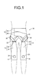
- FIG. 1 and FIG. 2 show a device for assisting joint exercise 10 as a first embodiment of the present invention.
- the device for assisting joint exercise 10 is for assisting bending and extending of the hip joints, and has a constitution including assist force transmission bands 12, 12 as a pair of assist force transmission sections at left and right extending across the hip joints, and a first mounting section 14 and a second mounting section 16 respectively attached to both end parts of the assist force transmission bands 12, 12 so that the first mounting section 14 is attached to one side and the second mounting section 16 is attached to the other side sandwiching the hip joints.
- the device for assisting joint exercise 10 is shown in a state worn by the user, and the outline of the user is shown by a double-dot-dash line.
- the front surface means the surface on the user's abdominal side (front surface)
- the rear surface means the surface on the user's back side (back surface)
- the vertical direction means the vertical direction in FIG. 1 , which coincides with the vertical direction.
- assistant force means the assisting force acting in the direction supplementing the force required for movement
- resist force means the assisting force acting in the direction resisting the force required for movement.
- the assist force transmission band 12 has a constitution whereby a first traction band 18 and a second traction band 20 which are respectively formed using fabric are connected by a connecting fitting 22 made of metal, and the part constituted by the first traction band 18 and the second traction band 20 is flexibly deformable.
- the first traction band 18 is formed with a thin band shaped fabric which gradually has a narrower width toward one end part side (in FIG. 1 , the top side), and in the state with the device for assisting joint exercise 10 worn, is arranged so as to cover the front surface of the user's thighs. Also, the first traction band 18 can be elastically deformed in the lengthwise direction (in FIG. 1 , the vertical direction) which is the direction of action of the tensile force by an electric motor 40 described later, and has smaller elasticity and limited deformation in the width direction (in FIG. 1 , the horizontal direction), and also has anisotropy of the deformation volume in relation to input in the lengthwise direction and width direction.
- the first traction band 18 preferably has elasticity of 0.3 kgf/cm or greater and 0.5 kgf/cm or less in the lengthwise direction.
- a ring shaped connecting fitting 22 is attached to the top end of the first traction band 18, and the first traction band 18 is connected to the second traction band 20 via the connecting fitting 22.
- the second traction band 20 is a band shape having a generally fixed width dimension, and is formed with fabric using fibers with low stretch properties.
- the second traction band 20 is connected with the first traction band 18 with the middle part inserted in the connecting fitting 22, thus constituting the assist force transmission band 12.
- the second traction band 20 does not absolutely have to be an item with suppressed stretch properties, and it is also possible to use an item having the same stretch properties formed using elastic fibers or the like the same as with the first traction band 18.
- the first mounting section 14 is provided underneath the first traction band 18 of the assist force transmission band 12.
- the first mounting section 14 is a sports supporter band used for protecting knee joints, and is formed with fabric or the like having stretch properties, and is worn wound on the user's knee joint.
- the first mounting section 14 is formed as an integral unit with the first traction band 18, and the first traction band 18 faces upward extending from the front surface part of the first mounting section 14.
- a partial through hole 24 is provided on the first mounting section 14, and by the partial through hole 24 being aligned with the user's kneecap, it is made not to obstruct bending and extending of the knee joint.
- both end parts of the second traction band 20 of the assist force transmission band 12 are attached to the second mounting section 16.
- the second mounting section 16 has a transmission band support belt 26 and a drive device support belt 28 respectively worn on the lower back, with one end part of the second traction band 20 attached to the transmission band support belt 26 and the other end part attached to the drive device support belt 28.
- the transmission band support belt 26 is formed by a band shaped fabric with low stretch properties, and is worn on the lower back of the user by being wound onto the lower back of the user and having both end parts connected using a surface fastener, snap, hook or the like. Also, a pair of guide fittings 30, 30 exhibiting a ring shape are provided on the transmission band support belt 26. In a state with the transmission band support belt 26 worn on the lower back, the guide fittings 30, 30 are arranged at both the left and right sides of the lower back. Then, one end part of the second traction band 20 is attached to the front part of the transmission band support belt 26 using mean such as sewing, adhesion, a snap, hook, surface fastener or the like.
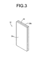
- the capacitance type sensor 32 is a flexible capacitance change type sensor which allows elastic deformation as shown for example in Japanese Unexamined Patent Publication No. 2010-43880 and Japanese Unexamined Patent Publication No. 2009-20006 , and as shown in FIG. 3 , has a constitution by which a pair of electrode films 36a, 36b formed using a conductive, elastic material are provided on both surfaces of a dielectric layer 34 formed using a dielectric elastic material. Also, the capacitance type sensor 32 is attached to the transmission band support belt 26 by one electrode film 36a being fixed to the inner surface of the back part of the transmission band support belt 26.
- the capacitance type sensor 32 detects changes in the acting pressure by bending and extending of the hip joint as changes in the capacitance that accompanies closeness and distance of the pair of electrode films 36a and 36b, and outputs the detection results to a control device 46 of a drive device 38 described later.
- the capacitance type sensors 32 are arranged as a left and right pair, and one capacitance type sensor 32 each is overlapped on the left and right buttock.
- the thickness dimension of the dielectric layer 34 and the pair of electrode films 36a and 36b is shown to be more enlarged than the length dimension and the width dimension, but preferably, the dielectric layer 34 as well as the pair of electrode films 36a and 36b have a thin film shape, and can be arranged without giving a sense of discomfort to the buttocks.
- the drive device support belt 28 the same as with the transmission band support belt 26, is formed with a band shaped fabric with low stretch properties, and is worn on the lower back of the user by being wound onto the lower back of the user and having both end parts connected using a surface fastener, snap, hook or the like. Also, with the drive device support belt 28, the back surface part extends downward further than the front surface part so as to have a large surface area, and the drive device 38 is fixed at that back surface part.
- the drive device 38 has the electric motor 40 as a drive source, a rotation shaft 42 that is rotationally driven by the electric motor 40, a power supply device 44 such as a battery or the like that supplies power to the electric motor 40, and the control device 46 for controlling the electric motor 40 based on the detection results of the capacitance type sensor 32.
- the electric motor 40 is a typical electric motor, and generates rotational drive force of the drive shaft 48 by power being conducted from the power supply device 44. Also, the rotational drive force exerted on the drive shaft 48 of the electric motor 40 is transmitted to the rotation shaft 42 via a speed reducing gear train (not illustrated).
- the rotation shaft 42 is a circular shaft shaped member supported so as to allow rotation in the circumference direction, and the other end part of the second traction band 20 is fixed to the outer circumference surface of the rotation shaft 42. By doing this, the other end part of the second traction band 20 is attached to the drive device support belt 28 via the drive device 38, and thus the assist force transmission band 12 is arranged across the hip joints.
- the second traction band 20 of the assist force transmission band 12 is wound onto the rotation shaft 42.
- the drive force by the electric motor 40 is transmitted in the lengthwise direction of the assist force transmission band 12 (lengthwise direction of the first traction band 18 and the second traction band 20), and is exerted as tensile force between the first mounting section 14 and the second mounting section 16.
- the assist force transmission band 12 extends in the transmission direction of the drive force of the electric motor 40.
- control of the electric motor 40 is executed by the presence or absence of power conduction to the electric motor 40 from the power supply device 44 and the conductivity direction (rotation direction of the drive shaft 48) being controlled by the control device 46.
- the control device 46 is equipped with a CPU, RAM, ROM or the like, and based on the capacitance type sensor 32 detection results (output signals), it detects hip joint bending exercise and extending exercise by the user, and controls power conduction to the electric motor 40 according to the detected hip joint exercise. By doing this, the tensile force exerted between the first mounting section 14 and the second mounting section 16 based on the drive force of the electric motor 40 is adjusted by the control device 46.
- the control device 46 identifies the walking movement stage (e.g. the stage of bending the hip joint and carrying the back leg to the front, or the stage of extending the hip joint and kicking the front leg to the ground or the like), and controls the power conduction to the electric motor 40 according to the identified walking movement stage.
- assisting force that reinforces the force required for the hip joint's bending exercise
- the movement accompanied with hip joint bending and extending is assisted.
- the control device 46 identifies that the user is trying to bend the hip joint based on the detection results of the capacitance type sensor 32, power is conducted to the electric motor 40 from the power supply device 44, and the rotation shaft 42 is rotated in one circumference direction.
- the second traction band 20 is wound by the rotation shaft 42, and the substantial length of the second traction band 20 becomes shorter, so the connecting fitting 22 externally fitted around the middle part of the second traction band 20 is pulled toward the second mounting section 16 side (top side) and displaced. Then, tensile force is exerted on the first mounting section 14 through the first traction band 18 attached to the connecting fitting 22, and the first mounting section 14 worn on the knee joint is pulled toward the second mounting section 16 side worn on the lower back. As a result, assist force acts so as to pull the knee joint to the lower back side in resistance to gravity, and assists the hip joint bending exercise. Based on the detected value of the capacitance type sensor 32, if the control device 46 adjusts the rotation volume of the rotation shaft 42 (power conduction time to the electric motor 40), just enough assist force is provided for the movement the user is trying to perform.
- the control device 46 identifies that the user is trying to extend the hip joint based on the detection results of the capacitance type sensor 32, power is conducted to the electric motor 40 from the power supply device 44 and the rotation shaft 42 is rotated in the other circumference direction.
- the winding of the second traction band 20 by the rotation shaft 42 is cancelled, and the substantial length of the second traction band 20 becomes longer, so the connecting fitting 22 externally fitted around the middle part of the second traction band 20 is displaced to the direction separating from the second mounting section 16 (bottom side) by its own weight or the like.
- the device for assisting joint exercise 10 is worn, a part of the force required when bending the hip joint is supplemented by the force generated by the electric motor 40, so for example when doing the movement of carrying the back leg to the front by bending the hip joint when walking, it is possible to perform the goal movement with small muscle strength. Therefore, using the device for assisting joint exercise 10, even when sufficient muscle strength is not available for performing movement by the user due to being elderly or disabled, it is possible to smoothly perform the target movement, and it becomes possible to prevent restriction of activities by the user.
- the first traction band 18 of the assist force transmission band 12 which is provided on the path for transmitting the generated drive force of the electric motor 40 as an assist force to the user's leg, can be elastically deformed in the force transmission direction. By doing this, the generated force of the electric motor 40 is exerted on the user's leg after being eased by the elastic deformation of the first traction band 18. Because of that, compared to when the generated drive force of the electric motor 40 is transmitted directly, the load on the user's joints and the like is reduced, and it is possible to prevent the problem of muscle pain and the like.
- the assist force exerted on the user's leg is 2 kgf to 5 kgf which is a relatively small force, and rather than forcibly causing movement, it is always based on the concept of supplementing insufficient muscle strength required for movement. Therefore, it is possible to perform the necessary assistance without placing a burden on the user's body.
- the elasticity in the force transmission direction of the first traction band 18 is set between 0.3 kgf and 0.5 kgf.
- the first traction band 18 has deformation limited in the direction roughly orthogonal to the force transmission direction.
- the first mounting section 14 formed as an integral unit with the first traction band 18 is restrained from stretching in the circumference direction (diameter expansion deformation or diameter reduction deformation), and the shape stability is increased. By doing this, during acting of the tensile force by the electric motor 40, the first mounting section 14 is held without coming off from the knee joint, and the assist force is transmitted effectively to the leg.
- the assist force by the device for assisting joint exercise 10 is exhibited when doing hip joint bending exercise, whereas it is canceled when doing hip joint extending exercise.
- the device for assisting joint exercise 10 is worn, while it assists hip joint bending exercise which requires exercise in resistance to gravity in a standing state, with hip joint extending exercise which is assisted by the action of gravity in a standing state, there is no acting of the assist force as a resist force, but instead smooth movement is realized. Therefore, even with walking movement performing repeated hip joint bending and extending or the like, there is no obstruction of the movement, and it is possible to provide the necessary assist force at appropriate times and to give appropriate assistance for movement.
- this kind of switching of assistance according to the user movement state is executed automatically by the control device 46 based on the detection results of the capacitance type sensor 32. Because of that, the user is able to obtain suitable assistance at a suitable time without requiring manual control by the user of the timing at which assist force is given, of the size of the assist force or the like.
- the capacitance type sensor 32 as the sensor, it is possible to obtain high precision detection results. Because of that, for example, if the assist force size or the like is adjusted based on the detection results, more appropriate assistance is possible. Furthermore, with the capacitance type sensor 32, the reduction in detection precision in relation to temperature change is small, and correction in relation to temperature change is easy, so it is possible to stably obtain correct detection results even when the temperature change is big. In addition, with the capacitance type sensor 32, since the detection precision decrease in relation to repeated input is small, it is possible to ensure sufficient durability, and daily use with everyday activities or the like can be realized.
- the assist force transmission section of this embodiment is made to be the assist force transmission band 12 formed of a band shaped thin cloth. Accordingly, it has sufficient flexibility, and compared to a device for assisting joint exercise having a hard exoskeleton, it is possible to put it on and take it off easily. Specifically, when the user wears the hard exoskeleton, the user has to adjust the joint bending angle to match the shape of the exoskeleton, and there are many cases when putting it on is difficult when sitting. However, with the device for assisting joint exercise 10 of this embodiment, the assist force transmission band 12 that connects the first mounting section 14 and the second mounting section 16 bends as needed.
- the assist force transmission band 12 is made sufficiently long, regardless of the degree of the bending angle of the user's joint, it is possible to attach the first mounting section 14 and the second mounting section 16 at respectively suitable positions.
- the assist force transmission band 12 being flexible, for example, it is possible to respectively put on the first mounting section 14 and the second mounting section 16 in a seated posture with the hip joint bent. Thus, it is possible to do the work of putting on and taking off the item from a position of ease.
- the device for assisting joint exercise 10 is light, and it can be easily handled even by elderly persons or the like for whom muscle strength has decreased.
- both the first mounting section 14 and the second mounting section 16 are also made of cloth, the overall device for assisting joint exercise 10 is lighter, and there are further improvements in handling including the task of putting on and taking off the device and the like.
- the assist force transmission band 12 made of thin cloth, in the state when worn, the assist force transmission band 12 curves easily in the thickness direction along the shape of the user's body surface. Because of that, with the device for assisting joint exercise 10, a good sense of wearing comfort is realized. Also, when worn with clothing over the device for assisting joint exercise 10, it is possible to prevent the assist force transmission band 12 from having dents and bumps occur which would make the device stand out, so it can be used easily for everyday activities. With this embodiment, both the first mounting section 14 and the second mounting section 16 are also thin. Therefore, by avoiding an odd visual appearance when wearing with clothing over the device for assisting joint exercise 10, it is easy to use this on a daily basis.
- the first mounting section 14 attached to the knee joint, and the second mounting section 16 attached to the lower back, it is possible to efficiently exert assist force on the leg while preventing making the length of the assist force transmission band 12 longer than necessary, as well as making the device for assisting joint exercise 10 smaller.
- the separation distance from the hip joint (the fulcrum during swinging of the thigh) to the first mounting section 14 (the action point) is larger, the tensile force acts efficiently on the first mounting section 14.
- the drive device 38 on the lower back for which there is little exercise volume during walking, it is possible to prevent the drive device 38 from obstructing the walking movement.
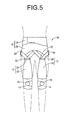
- FIG. 5 and FIG. 6 show a device for assisting joint exercise 50 as a second embodiment of the present invention.
- the device for assisting joint exercise 50 is constituted including the assist force transmission band 12 and the assist force transmission band 52 as the assist force transmission section, and the first mounting section 14 and the second mounting section 16 provided at both ends of that.
- the assist force transmission band 52 is constituted including a third traction band 54 and a fourth traction band 56, and these are arranged across the hip joint on the user's back surface side, connecting the first mounting section 14 and the second mounting section 16.
- the third traction band 54 extends upward from the top end of the back surface side of the first mounting section 14, with the bottom end fixed on the first mounting section 14, and the top end fixed to the connecting fitting 22.
- the third traction band 54 is formed as a separate item from the first mounting section 14 and connected by a means such as a seam or the like, and it is possible to realize both of the required performance of the third traction band 54 and the required performance of the first mounting section 14 at a high level.
- the third traction band 54 has a gradually narrower width facing upward, and has a shape that allows deformation of the thigh muscle or the like when bending and extending the hip joint.
- the third traction band 54 is also elastically deformable in the lengthwise direction (in FIG. 6 , the vertical direction) which is the action direction of the tensile force by the electric motor 40 of the drive device 38.
- the fourth traction band 56 is inserted through the connecting fitting 22 attached to the third traction band 54.
- the fourth traction band 56 is in a thin band form having a generally constant width dimension, and is formed using fibers which do not stretch easily, so elastic deformation is restricted.
- one end part is fixed by a means such as a seam or the like to the transmission band support belt 26, and the other end part is fixed to the rotation shaft 42 of the drive device 38.
- the third traction band 54 is connected to the middle part of the fourth traction band 56, and the first mounting section 14 and the second mounting section 16 are connected to each other by the third and fourth traction bands 54 and 56.
- the rotation shaft 42 is rotated to one circumference direction side by the drive force of the electric motor 40 so that the fourth traction band 56 is wound on the rotation shaft 42. Consequently, tensile force is exerted between the first mounting section 14 and the second mounting section 16 through the third and fourth traction bands 54 and 56. Meanwhile, by the rotation shaft 42 rotating to the other circumference direction side, the winding of the fourth traction band 56 by the rotation shaft 42 is cancelled, so the aforementioned tensile force is cancelled.
- the electric motor 40 for exerting tensile force on the fourth traction band 56 may be provided separately from the electric motor 40 for exerting tensile force on the second traction band 20, or alternatively, it is also possible to have tensile force by a common electric motor 40 selectively exerted on either one of the second traction band 20 or the fourth traction band 56.
- the tensile force exerted between the first mounting section 14 and the second mounting section 16 through the third and fourth traction bands 54 and 56 is cancelled, and acting of the tensile force as an assist force is prevented.
- strengthening of the muscle strength of the muscles around the hip joint and the like is efficiently realized. If control is done so that tensile force exerted on the first mounting section 14 through the first and second traction bands 18 and 20 is canceled when the hip joint is bent, and acts when the hip joint is extended, it is possible to add a load in relation to the exercise of extending the hip joint. It is possible to more effectively realize strengthening of the muscle strength thereby.
- assisting force assist force
- the tensile force exerted on the first mounting section 14 through the third and fourth traction bands 54 and 56 is cancelled when doing bending exercise of the hip joint, while being acted when doing extending exercise of the hip joint.
- assist force is exerted through the first and second traction bands 18 and 20 for hip joint bending exercise, and assist force is exerted through the third and fourth traction bands 54 and 56 for hip joint extending exercise.
- the device for assisting joint exercise 50 it is possible to selectively use, according to user's needs, function as an assisting device for aiding movement such as walking or the like, or function as an assisting device for efficiently strengthening muscle strength of the muscles around the hip joints during rehabilitation or the like.
- assisting force is exerted not only for hip joint bending exercise but also for extending exercises, so user movement is more effectively assisted.
- the third and fourth traction bands 54 and 56 are provided so as to exhibit assisting force even for hip joint extending exercise. Accordingly, when the device for assisting joint exercise 50 is put on in a seated state, after putting it on, it is also possible to start the movement assistance by the device while still in the seated posture, and to assist the standing up movement.
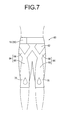
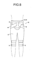
- FIG. 7 and FIG. 8 show a device for assisting joint exercise 60 as a third embodiment of the present invention.
- This device for assisting joint exercise 60 has a main unit 62 exhibiting a pants (leggings) shape which adheres tightly to the body surface covering from the lower back to below the knees.
- This main unit 62 is formed with fabric that has excellent stretch properties that allow elastic deformation according to the user's body shape, and deforms according to the user's body shape or the like.
- an assist force transmission section 64 is provided on the main unit 62.
- the assist force transmission section 64 is a thin band shaped fabric, and is equipped integrally with a first traction section 66 extending vertically so as to cover the front surface of the thigh, and a second traction section 68 extending diagonally upward branching left and right at a designated angle from the top end of the first traction section 66.
- both the first traction section 66 and the second traction section 68 of the assist force transmission section 64 are allowed elastic deformation in the lengthwise direction (in FIG. 7 , the vertical direction) which is the action direction of tensile force by the electric motor 40 of the drive device 38, while being restricted from elastic deformation in the width direction.
- This assist force transmission section 64 is provided integrally during weaving and formed as an integral unit with the main unit 62.
- a first mounting section 70 is provided below the first traction section 66 of the assist force transmission section 64.
- the first mounting section 70 is generally ring shaped, and is worn so as to generally cover across the entire circumference of the knee joint.
- the first mounting section 70 uses the same fabric as the first traction section 66, and is provided as an integral unit with the main unit 62 and the first traction section 66.
- the first mounting section 70 is restricted from elastic deformation in the circumference direction, so displacement from the knee joint is suppressed.
- the part that covers the front surface of the knee joint is interwoven as an integral unit with the main unit 62, and the parts that cover the back surface from the side surface of the knee joints extend in respective band forms separating from the main unit 62 at the left and right side surface parts.
- surface fasteners (not illustrated) are provided on the left and right pair of band shaped parts of the first mounting section 70 separating from the main unit 62 at the left and right side surface parts. Then, by pulling those band shaped parts in the circumference direction and tightening the knee joint when necessary and connecting to each other by the surface fasteners, the first mounting section 70 is aligned to the knee joint.
- a part formed by a material that has excellent stretch properties the same as the main unit 62 is provided on the front surface center part of the first mounting section 70.
- the end part extending to the inside branching laterally is held tightened by the drive device support belt 28.
- the side extending to the outside branching laterally is separated from the main unit 62 at the side of the lower back so the end part forms a band shape, and is fixed to the rotation shaft 42 of the drive device 38.
- the drive device 38 of this embodiment is equipped with one electric motor 40 for which the rotation direction of the drive shaft 48 is controlled by the control device 46.
- the rotation shafts 42 and 42 connected one each to the left and right assist force transmission sections 64 and 64 are rotated by the one electric motor 40.
- the left side assist force transmission section 64 is inserted from the back surface side in the drive device 38 and fixed to the rotation shaft 42, while the right side assist force transmission section 64 is inserted from between the drive device support belt 28 and the drive device 38, and fixed to the rotation shaft 42.
- the bottom end part is attached to the first mounting section 14, and the top end part is attached to the drive device support belt 28 as the second mounting section, and arranged across the hip joints.
- the device for assisting joint exercise 60 constituted in this way, the same as with the device for assisting joint exercise 10 shown in the first embodiment, tensile force is exerted between the first mounting section 70 and the second mounting section 16 through the assist force transmission section 64, and it is possible to assist hip joint exercise including walking.
- the device for assisting joint exercise 60 has the assist force transmission section 64 interwoven to be provided as an integral unit with the pants shaped main unit 62, so it is possible to easily put it on and take it off with a simple action the same as with pants. Furthermore, simply by correctly putting on the main unit 62, the assist force transmission section 64 is arranged at an accurate position, and it is possible to efficiently obtain assisting force. In addition, even when worn under clothing, the problem of bumps and dents arising and causing bulkiness does not occur easily, so other people are not given a strange visual impression easily. Moreover, it is possible to avoid problems of the movement of the user being restricted and the freedom of choice of clothing being small.
- the assist force transmission section is also possible to provide the assist force transmission section as an integral unit with a shirt form main unit in the same manner as with this embodiment.
- the main unit in clothing form worn so as to cover the joints can be prepared according to the joint for which movement is to be assisted.
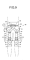
- FIG. 9 shows a device for assisting joint exercise 80 as a fourth embodiment of the present invention.
- the device for assisting joint exercise 80 has a constitution by which an assist force transmission band 82 as the assist force transmission section connects the first mounting section 14 and the second mounting section 16.
- the assist force transmission band 82 is constituted including a first traction band 84, a second traction band 86, and a third traction band 88.
- the first through third traction bands 84, 86, and 88 are respectively formed with thin band shaped fabric extending at a generally fixed width dimension.
- the first and second traction bands 84 and 86 are made to be elastically deformable in the lengthwise direction (in FIG. 9 , the vertical direction) which is the action direction of the tensile force by the electric motor 40 of the drive device 38, while the third traction band 88 has elastic deformation restricted in the lengthwise direction.
- an adjustable fitting 90 is provided on the second traction band 86, and this makes it possible to easily adjust the length of the second traction band 86 according to physical build.
- the top end of the first traction band 84 and the bottom end of the second traction band 86 are respectively attached to a ring shaped first connecting fitting 92, and the first traction band 84 and the second traction band 86 are connected via the first connecting fitting 92. Furthermore, the top end of the second traction band 86 is attached to a ring shaped second connecting fitting 94, and the third traction band 88 is inserted through the second connecting fitting 94, so that the top end of the second traction band 86 and the middle part of the third traction band 88 are connected via the second connecting fitting 94.
- first and second traction bands 84 and 86 fix the first and second traction bands 84 and 86 to the first and second connecting fittings 92 and 94 so they can't be removed, but it is preferable to attach them using a hook, snap, surface fastener or the like so they are removable. With this embodiment, they are attached in a removable state using a snap 96.
- first traction band 84 is attached to the top end of the front surface part of the first mounting section 14.
- the attachment of the first traction band 84 to the first mounting section 14 can be fixing by sewing or adhesion, but it is preferable to attach it so as to be detachable using a hook, snap, surface fastener or the like.
- the third traction band 88 one of the end parts extends circling around to the back part from the side part of the lower back, and is fixed to the rotation shaft 42 of the drive device 38 shown in FIG 4 . Meanwhile, the other end part of the third traction band 88 is attached to the drive device support belt 28 of the second mounting section 16 at the front of the lower back.
- a hook fitting 98 is attached to the other end part of the third traction band 88, and that is attached in a state that is detachable to a ring shaped or half ring shaped attachment fitting 100 provided on the front surface part of the drive device support belt 28.
- a plurality of the attachment fittings 100 are provided aligned in the circumference direction on the drive device support belt 28, and by suitably selecting from among that plurality the attachment fitting 100 for attaching the hook fitting 98, it is possible to adjust the length of the third traction band 88.
- the first mounting section 14 and the second mounting section 16 are connected by the assist force transmission band 82 constituted by the first through third traction bands 84, 86, and 88.
- the assist force transmission band 82 constituted by the first through third traction bands 84, 86, and 88.
- the assist force transmission band 82 is constituted by the first through third traction bands 84, 86, and 88, and they are respectively connected by the connecting fittings 92 and 94. Because of that, in cases such as when any of the first through third traction bands 84, 86, and 88 are damaged, it is possible to remove and replace just the damaged part from the connecting fittings 92 and 94, so maintainability is excellent.
- the first mounting section for using the device for assisting joint exercise for hip joint exercise assistance is attached to the knee joint.
- the first mounting section it will suffice for the first mounting section to be provided on the opposite side to the second mounting section across the lower back, and when the second mounting section is worn on the lower back, it is possible to obtain generally the same effect even by the first mounting section being attached to the thigh.
- the first mounting attachment position is too close to the hip joint, it is difficult for the assist force to act effectively, so when the first mounting section is attached to the thigh, it is preferable to attach it to a position near the knee joint.
- the arrangement position of the drive device is not limited to being on the lower back.
- the drive device when assisting bending and extending exercise of the shoulder joint, by providing the drive device on the user's back, it is possible to make the device for assisting joint exercise more compact by shortening the assist force transmission path without obstructing user's movement.
- a sensor for detecting user's movement this is not limited to being a capacitance type sensor.
- a resistance change type sensor that detects user's movement based on changes in the resistance value by action of a force. If this kind of resistance change type sensor is used, because it is possible to do measurement using DC voltage, simplifying the measuring circuit is easy, and realizing smaller size and lower costs is easy. In fact, since the resistance value changes sharply even with the action of a small force, it is possible to detect over a wide range, from tiny exercise to big exercise of the joints.
- the resistance change type sensor for example, an item having flexibility like that shown in Japanese Unexamined Patent Publication No. 2008-69313 can be suitably used. It is also possible to use a combination of a plurality of different types of sensors with different structures and detection methods, such as using the capacitance type sensor and resistance change type sensor in combination or the like.
- the sensor arrangement positions shown in the embodiments noted above are simply examples, and as long as it is possible to detect user's movement, the arrangement mode is not particularly limited.
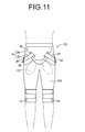
- a capacitance type sensor 112 is arranged on the back surface of the first traction band 18 (surface overlaid on the thigh). By so doing, it is also possible to detect the gripping pressure between the first traction band 18 and the thigh, which comes with deformation of the thigh muscle when bending the hip joint, as a change in capacitance.
- the structure includes a pants (leggings) shaped sensor holding suit 124 equipped with a capacitance type sensor 122. Then, the assist force transmission band 12 as well as the first and second mounting sections 14 and 16 are put on after putting on the sensor holding suit 124.
- the capacitance type sensor 11 also have the basic structure that is the same as that of the capacitance type sensor 32 shown in the embodiment, so their explanation will be omitted here. Furthermore, it is also possible to use a combination of the capacitance type sensor 112 and the capacitance type sensor 122, making it possible to more precisely detect movement.
- the assist force transmission section is provided at least at the front surface side.
- the assist force transmission section is also possible to provide the assist force transmission section only on the back side.
- the assist force transmission section is acceptable as long as it is suitably arranged considering the mobility of the joints and the like.
- the assist force transmission section is not limited to being an item having flexibleness (flexibility) for the entire object, but can also have a hard part formed of metal, plastic or the like as long as it is only partial. Furthermore, it is possible to have the entire assist force transmission section be elastically deformable in the force transmission direction, or alternatively to have the assist force transmission section allow partial elastic deformation in the force transmission direction.
- the transmission band support belt 26 and the drive device support belt 28 do not absolutely have to be provided independently.
- the end part of the assist force transmission band 12 being fixed to the front part of the drive device support belt 28, and simultaneously equipping a function with the drive device support belt 28 as the transmission band support belt.
- the assist force transmission band 12 does not have to be formed as a separate item in relation to the transmission band support belt 26.
- the assist force transmission band 12 can be formed as an integral unit with the drive device support belt 28.
- the device for assisting joint exercise for assisting hip joint bending and extending exercise is shown, but the device for assisting joint exercise of the present invention can also be used for assisting bending and extending exercise of joints other than the hip joint, such as the knee joint, shoulder joint, elbow joint and the like.
Abstract
Description
- The present invention relates to a device for assisting joint exercise which, when a user is bending and extending his joints, exerts on the user an assist force which makes it possible to realize bending and extending, or exerts a load (resist force) for efficiently strengthening the muscle strength required for bending and extending.
- From the past, to support movement such as walking or the like for physically disabled persons who have lost muscle strength or for elderly persons whose muscle strength has diminished, wearable type movement assistance devices like that shown in Japanese Patent No.
4200492 - However, the wearable type movement assistance device noted in Patent Document 1 is a so-called exoskeleton type assistance device, and by a hard exoskeleton arm arranged at the side of the user's body being driven by a motor at the joint sections, the arm, leg or the like of the user wearing the exoskeleton arm moves together with the exoskeleton arm.
- However, with assistive devices using this kind of hard exoskeleton, it was necessary to accurately measure the physical build of the user (thigh and lower leg length and the like) and to precisely adjust the length of the exoskeleton arm, and when this adjustment was not done appropriately, excessive force could be applied to the joints during exercise, which could lead to a very dangerous situation. Also, the work of putting on and taking off the exoskeleton type assistance device is not easy for a user who requires assistance to move, and a great deal of effort and time is required to put it on and take it off. Because of that, it was difficult to wear and use for everyday purposes with the goal of supplementing reduced muscle strength to make movement easier. In fact, when using an assistance device having a large exoskeleton, it is virtually impossible for the user to move in resistance to the drive force of the exoskeleton with his own muscle strength, and there was absolutely no consideration taken for using this kind of assistance device for walking training or the like with the goal of efficient strengthening of muscle strength. Also, to control the movement of the assistance device, it is necessary to perform measurement of the surface electromyography, so there was also the problem of the user having to wear numerous surface electrodes (normally 18).
- In Japanese Unexamined Patent Publication No.
2010-110464 -
- Patent Document 1: Japanese Patent No.
4200492 - Patent Document 2: Japanese Unexamined Patent Publication No.
2010-110464 - The present invention has been developed with the circumstances described above as the background, and the problem it addresses is to provide a device for assisting joint exercise with a novel structure which can be easily put on and taken off by the user with a simple structure that is light, and which can also be used to effectively perform muscle strength strengthening training rather than solely movement assistance.
- Specifically, a first mode of the present invention is a device for assisting joint exercise comprising: a flexible assist force transmission section; a first mounting section and a second mounting section, which are provided at both end portions of the assist force transmission section, the first mounting section adapted to be mounted on one site and the second mounting section adapted to be mounted on another site sandwiching a user's joint; and a drive source that exerts tensile force between the first mounting section and the second mounting section through the assist force transmission section, wherein at least a portion of the assist force transmission section is elastically deformable in an acting direction of the tensile force by the drive source.
- With this kind of device for assisting joint exercise noted in the first mode, by the assist force transmission section having flexibility and allowing deformation, the user can put on and take this off more easily than with a device for assisting joint exercise having a hard exoskeleton. Because of that, when movement is difficult due to a decrease in muscle strength or the like due to aging or disability, with a simple task for putting on and taking off the device for assisting joint exercise, it is possible to realize performing of a target movement using the force obtained from the device for assisting joint exercise as an assist force, and efficient strengthening of the muscle strength necessary for a target movement with the force obtained from the device for assisting joint exercise as a load. As a result, it is possible to prevent on an everyday basis the restriction of activities in the elderly or the like due to locomotive syndrome (musculoskeletal system syndrome) due to movement disorders, and it is also possible to perform high efficiency muscle strength strengthening training even during daily activities. Thus, it is possible to quickly eliminate temporary muscle strength decreases and the like due to various injuries or illnesses and bed rest.
- Furthermore, by the assist force transmission section being flexible, it is less likely for the user to be given a sense of being restrained, and the wearing comfort is improved. Because of that, the physical and mental burden on the user due to wearing of the device for assisting joint exercise is reduced, and it becomes possible to wear it continuously over a long period.
- Also, by having at least a portion of the assist force transmission section be able to elastically deform in the tensile force acting direction, the tensile force exerted by the drive source is eased by the elasticity of the assist force transmission section between the first mounting section and the second mounting section. Because of that, it is possible to have the assisting force act with a buffering effect so as not to apply an excessive load on the user's joints or the like.
- A second mode of the present invention is the device for assisting joint exercise according to the first mode, further comprising a sensor for detecting bending and extending of the user's joint, and a control device arranged for controlling the drive source based on detection results of the sensor.
- With the second mode, the assisting force is automatically controlled based on the sensor detection results, so it is possible to obtain suitable assistance at a suitable time without requiring a troublesome operation such as a switch operation or the like.
- A third mode of the present invention is the device for assisting joint exercise according to the second mode, wherein the sensor can detect bending and extending of the user's joint based on force exerted on the sensor in accordance with the bending and extending of the user's joint.
- With the third mode, since bending and extending of the joints is detected based on the force exerted on the sensor, high precision detection is possible, and it is possible to efficiently assist user's movement.
- A fourth mode of the present invention is the device for assisting joint exercise according to the third mode, wherein the sensor includes at least one of a capacitance type sensor and a resistance change type sensor.
- With the fourth mode, by using the capacitance type sensor, it is possible to detect the force exerted on the sensor with high precision, and possible to suitably assist movement. Furthermore, the decrease in detection precision is small even when force is repeatedly input, and since the reproducibility of the detection results are good, durability is improved. Yet further, with the capacitance type sensor, the variation range of the detection precision in relation to temperature change is small, and it is easy to correct the detection precision by adjusting the initial value in relation to temperature change. Therefore, even when the temperature change is large, stable detection is realized.
- Meanwhile, if the resistance change type sensor is used, the resistance value changes sharply in relation to the force exerted on the sensor, so it is possible to have control with little time delay, making it possible to realize movement assistance with suitable timing. Furthermore, the resistance change type sensor can do detection across a broad range from cases when the force acting on the sensor is small to cases when it is large, so it is possible to obtain effective detection results both in cases when the bending of the joints is small and in cases when it is large.
- A fifth mode of the present invention is the device for assisting joint exercise according to any one of the first through fourth modes, wherein the assist force transmission section is in a band form that extends in a force transmission direction.
- With the fifth mode, by having the assist force transmission section be in band form, the mass of the assist force transmission section is small, and it is possible to make the device for assisting joint exercise lighter. As a result, an improvement in the ease of wearing and a decrease in the burden due to wearing are realized, so it is possible to obtain a device for assisting joint exercise that is easier to handle.
- Also, by having the assist force transmission section be thin, it is easy to allow bending in the thickness direction, so by the assist force transmission section deforming according to the surface shape of the user's body, the sense of the device as a foreign object is reduced, and the wearing comfort is increased. Furthermore, if the assist force transmission section is thin, when clothing is worn after putting on the device for assisting joint exercise, bumps in the clothing due to the assist force transmission section do not occur easily, and because the device for assisting joint exercise is prevented from standing out, it is easier to make daily use of it for everyday activities.
- A sixth mode of the present invention is the device for assisting joint exercise according to any one of the first through fifth modes, wherein the assist force transmission section is provided as an integral unit with a main unit in clothing form, and by wearing the main unit, the assist force transmission section is arranged across the user's joint.
- With the sixth mode, by having the assist force transmission section provided as an integral unit with the main unit in clothing form, wearing and arranging in a designated position of the assist force transmission section can be completed easily by putting the main unit on in the same manner as clothing. Because of that, even for an elderly or disabled person with decreased muscle strength, it is easy to use for daily life, and it is also possible to effectively obtain movement assistance with the goal of appropriately transmitting tensile force by the drive source.
- A seventh mode of the present invention is the device for assisting joint exercise according to any one of the first through sixth modes, wherein the portion of the assist force transmission section which is elastically deformable is an item for which, compared to elasticity in the acting direction of the tensile force by the drive source, elasticity in a direction orthogonal to that is smaller.
- With the seventh mode, in the length direction which is the tensile force acting direction, by having the tensile force by the drive source transmitted with sufficient buffering, it is possible to suppress the load on the user's joints and the like. Also, by suppressing deformation in the width direction orthogonal to the tensile force acting direction, selective transmission of force is realized, and it is also possible to improve shape stability and durability.
- An eighth mode of the present invention is the device for assisting joint exercise according to any one of the first through seventh modes, wherein the assist force transmission section is arranged across at least one of a hip joint and a knee joint of the user.
- With the eighth mode, by having assisting force exerted on the leg, bending and extending is assisted for at least one of the hip joint or the knee joint. Because of that, for example, it is possible to realize easing of leg exercise or strengthening of leg muscle strength by an assisting force (assist force) that supplements insufficient muscle strength necessary for bending and extending the joints, or an assisting force (resist force) acting as a resistive load on the muscle strength necessary for bending and extending the joints.
- A ninth mode of the present invention is the device for assisting joint exercise according to the eighth mode, wherein the first mounting section is attached to at least one of a thigh and the knee joint of the user while the second mounting section is attached to a lower back of the user so that the assist force transmission section is arranged across the hip joint.
- With the ninth mode, the tensile force by the drive source acts as an assist force for reinforcing the muscle strength needed for bending and extending the hip joint, or as resist force for effectively strengthening the muscle strength of the muscles surrounding the hip joint or the like, so walking movement that involves hip joint bending and extending exercise and the like is assisted by the device for assisting joint exercise.
- A tenth mode of the present invention is the device for assisting joint exercise according to the ninth mode, wherein the drive source is attached to the second mounting section.
- With the tenth mode, the drive source is supported by the second mounting section attached to the lower back which has smaller movement than the thigh during bending and extending of the hip joint. Accordingly, the drive source is supported stably, and also, the drive source which can easily become relatively heavy is arranged at the lower back which has smaller movement, so inertia or the like acting on the drive source is prevented from becoming a load on the user's leg.
- Also, the first mounting section is attached to the thigh or knee joint, and the second mounting section that supports the drive source is attached to the lower back, so both the first mounting section and the second mounting section are arranged at positions near the hip joint. Because of that, it is possible to shorten the length of the assist force transmission section arranged across the hip joints, advantageously lightening or making more compact the device for assisting joint exercise, and also making it possible to easily put on the device for assisting joint exercise.
- An eleventh mode of the present invention is the device for assisting joint exercise according to any one of the first through tenth modes, wherein the tensile force by the drive source acts as an assist force that reinforces force necessary for joint bending and extending exercise.
- With the eleventh mode, when there has been a decrease in the muscle strength needed for joint bending and extending exercise, the tensile force by the drive force is transmitted via the assist force transmission band, and by acting as an assist force, supplements the insufficient muscle strength, making it possible to perform the target joint bending and extending exercise. By doing this, for example, when exercise is difficult due to decreased muscle strength in an elderly person or the like, it is possible to supplement the user's movement as needed, and to easily maintain a state for which exercise is possible. As a result, it is possible to prevent limitation of activities due to reduced muscle strength as well as to prevent further reduction of muscle strength, making it possible to prevent worsening of the condition.
- A twelfth mode of the present invention is the device for assisting joint exercise according to any one of the first through eleventh modes, wherein the tensile force by the drive source acts as a resist force resisting the force necessary for joint bending and extending exercise.
- With the twelfth mode, for example, when there is a temporary decrease in the muscle strength needed for joint bending and extending exercise due to injury or illness or the like, the assisting force by the drive source acts as a load (resist force) daringly in the direction resisting the force necessary for the movement. Accordingly, it is possible to efficiently implement rehabilitation in an attempt to recover function by strengthening reduced muscle strength. Also, it is possible to effectively strengthen muscle strength by the action of the resist force, so it is possible to efficiently achieve the goal of preventing a decrease in muscle strength due to insufficient amount of exercise or the like when used by healthy persons.
- With the present invention, by exerting tensile force via the assist force transmission section between the first mounting section and the second mounting section arranged at each side sandwiching the joint, bending and extending of the joint is assisted. Therefore, it is possible to supplement insufficient muscle strength, or to try to efficiently strengthen muscle strength. In fact, the assist force transmission section can be elastically deformed in the acting direction of the tensile force by the drive source, so that the tensile force by the drive source is buffered when exerted on the user. Thus, excess load on the joints is prevented, reducing the burden on the user. Furthermore, by the assist force transmission section having flexibility, attachment and detachment can be done easily as necessary, making it possible to use for long periods because of the excellent wearing comfort.
-
-
FIG. 1 is a front view showing a device for assisting joint exercise according to a first embodiment of the present invention. -
FIG. 2 is a back view of the device for assisting joint exercise shown inFIG. 1 . -
FIG. 3 is a perspective view of a capacitance type sensor constituting the device for assisting joint exercise shown inFIG. 1 . -
FIG. 4 is a drawing showing an internal structure of a drive device with the back view of the device for assisting joint exercise shown inFIG. 2 . -
FIG. 5 is a front view showing a device for assisting joint exercise according to a second embodiment of the present invention. -
FIG. 6 is a back view of the device for assisting joint exercise shown inFIG. 5 . -
FIG. 7 is a front view showing a device for assisting joint exercise according to a third embodiment of the present invention. -
FIG. 8 is a back view of the device for assisting joint exercise shown inFIG. 7 . -
FIG. 9 is a front view showing a device for assisting joint exercise according to a fourth embodiment of the present invention. -
FIG. 10 is a front view showing a device for assisting joint exercise according to another embodiment of the present invention. -
FIG. 11 is a back view showing a device for assisting joint exercise according to yet another embodiment of the present invention. - Following, we will describe embodiments of the present invention while referring to drawings.
-
FIG. 1 andFIG. 2 show a device for assistingjoint exercise 10 as a first embodiment of the present invention. The device for assistingjoint exercise 10 is for assisting bending and extending of the hip joints, and has a constitution including assistforce transmission bands first mounting section 14 and asecond mounting section 16 respectively attached to both end parts of the assistforce transmission bands section 14 is attached to one side and thesecond mounting section 16 is attached to the other side sandwiching the hip joints. InFIG. 1 andFIG. 2 , the device for assistingjoint exercise 10 is shown in a state worn by the user, and the outline of the user is shown by a double-dot-dash line. Also, in the description hereafter, the front surface means the surface on the user's abdominal side (front surface), the rear surface means the surface on the user's back side (back surface), and the vertical direction means the vertical direction inFIG. 1 , which coincides with the vertical direction. Also, in the description hereafter, "assist force" means the assisting force acting in the direction supplementing the force required for movement, and "resist force" means the assisting force acting in the direction resisting the force required for movement. - In more detail, the assist
force transmission band 12 has a constitution whereby afirst traction band 18 and asecond traction band 20 which are respectively formed using fabric are connected by a connectingfitting 22 made of metal, and the part constituted by thefirst traction band 18 and thesecond traction band 20 is flexibly deformable. - The
first traction band 18 is formed with a thin band shaped fabric which gradually has a narrower width toward one end part side (inFIG. 1 , the top side), and in the state with the device for assistingjoint exercise 10 worn, is arranged so as to cover the front surface of the user's thighs. Also, thefirst traction band 18 can be elastically deformed in the lengthwise direction (inFIG. 1 , the vertical direction) which is the direction of action of the tensile force by anelectric motor 40 described later, and has smaller elasticity and limited deformation in the width direction (inFIG. 1 , the horizontal direction), and also has anisotropy of the deformation volume in relation to input in the lengthwise direction and width direction. Thefirst traction band 18 preferably has elasticity of 0.3 kgf/cm or greater and 0.5 kgf/cm or less in the lengthwise direction. - Also, a ring shaped connecting fitting 22 is attached to the top end of the
first traction band 18, and thefirst traction band 18 is connected to thesecond traction band 20 via the connectingfitting 22. Thesecond traction band 20 is a band shape having a generally fixed width dimension, and is formed with fabric using fibers with low stretch properties. Thesecond traction band 20 is connected with thefirst traction band 18 with the middle part inserted in the connectingfitting 22, thus constituting the assistforce transmission band 12. Thesecond traction band 20 does not absolutely have to be an item with suppressed stretch properties, and it is also possible to use an item having the same stretch properties formed using elastic fibers or the like the same as with thefirst traction band 18. - Also, the first mounting
section 14 is provided underneath thefirst traction band 18 of the assistforce transmission band 12. Thefirst mounting section 14 is a sports supporter band used for protecting knee joints, and is formed with fabric or the like having stretch properties, and is worn wound on the user's knee joint. Also, the first mountingsection 14 is formed as an integral unit with thefirst traction band 18, and thefirst traction band 18 faces upward extending from the front surface part of the first mountingsection 14. A partial throughhole 24 is provided on the first mountingsection 14, and by the partial throughhole 24 being aligned with the user's kneecap, it is made not to obstruct bending and extending of the knee joint. - Also, both end parts of the
second traction band 20 of the assistforce transmission band 12 are attached to thesecond mounting section 16. Thesecond mounting section 16 has a transmissionband support belt 26 and a drivedevice support belt 28 respectively worn on the lower back, with one end part of thesecond traction band 20 attached to the transmissionband support belt 26 and the other end part attached to the drivedevice support belt 28. - The transmission
band support belt 26 is formed by a band shaped fabric with low stretch properties, and is worn on the lower back of the user by being wound onto the lower back of the user and having both end parts connected using a surface fastener, snap, hook or the like. Also, a pair ofguide fittings band support belt 26. In a state with the transmissionband support belt 26 worn on the lower back, theguide fittings second traction band 20 is attached to the front part of the transmissionband support belt 26 using mean such as sewing, adhesion, a snap, hook, surface fastener or the like. - Furthermore, a pair of
capacitance type sensors 32 are attached as the sensor to the transmissionband support belt 26. Thecapacitance type sensor 32 is a flexible capacitance change type sensor which allows elastic deformation as shown for example in Japanese Unexamined Patent Publication No.2010-43880 2009-20006 FIG. 3 , has a constitution by which a pair ofelectrode films dielectric layer 34 formed using a dielectric elastic material. Also, thecapacitance type sensor 32 is attached to the transmissionband support belt 26 by oneelectrode film 36a being fixed to the inner surface of the back part of the transmissionband support belt 26. - Then, in the state with the transmission
band support belt 26 worn, thecapacitance type sensor 32, with theother electrode film 36b overlapping the user's buttocks, is sandwiched between the buttocks and the transmissionband support belt 26. By doing this, thecapacitance type sensor 32 detects changes in the acting pressure by bending and extending of the hip joint as changes in the capacitance that accompanies closeness and distance of the pair ofelectrode films control device 46 of adrive device 38 described later. As shown by the dotted line inFIG 2 , thecapacitance type sensors 32 are arranged as a left and right pair, and onecapacitance type sensor 32 each is overlapped on the left and right buttock. Also, inFIG. 3 , the thickness dimension of thedielectric layer 34 and the pair ofelectrode films dielectric layer 34 as well as the pair ofelectrode films - Meanwhile, as shown in
FIG. 1 andFIG. 2 , the drivedevice support belt 28, the same as with the transmissionband support belt 26, is formed with a band shaped fabric with low stretch properties, and is worn on the lower back of the user by being wound onto the lower back of the user and having both end parts connected using a surface fastener, snap, hook or the like. Also, with the drivedevice support belt 28, the back surface part extends downward further than the front surface part so as to have a large surface area, and thedrive device 38 is fixed at that back surface part. - As shown in
FIG. 4 , thedrive device 38 has theelectric motor 40 as a drive source, arotation shaft 42 that is rotationally driven by theelectric motor 40, apower supply device 44 such as a battery or the like that supplies power to theelectric motor 40, and thecontrol device 46 for controlling theelectric motor 40 based on the detection results of thecapacitance type sensor 32. - The
electric motor 40 is a typical electric motor, and generates rotational drive force of thedrive shaft 48 by power being conducted from thepower supply device 44. Also, the rotational drive force exerted on thedrive shaft 48 of theelectric motor 40 is transmitted to therotation shaft 42 via a speed reducing gear train (not illustrated). Therotation shaft 42 is a circular shaft shaped member supported so as to allow rotation in the circumference direction, and the other end part of thesecond traction band 20 is fixed to the outer circumference surface of therotation shaft 42. By doing this, the other end part of thesecond traction band 20 is attached to the drivedevice support belt 28 via thedrive device 38, and thus the assistforce transmission band 12 is arranged across the hip joints. - Then, by the
rotation shaft 42 being rotated in one circumference direction by the drive force exerted from thedrive shaft 48 of theelectric motor 40, thesecond traction band 20 of the assistforce transmission band 12 is wound onto therotation shaft 42. By doing this, the drive force by theelectric motor 40 is transmitted in the lengthwise direction of the assist force transmission band 12 (lengthwise direction of thefirst traction band 18 and the second traction band 20), and is exerted as tensile force between the first mountingsection 14 and thesecond mounting section 16. As is clear from the description above, the assistforce transmission band 12 extends in the transmission direction of the drive force of theelectric motor 40. Meanwhile, when therotation shaft 42 is rotated in the other circumference direction by theelectric motor 40, winding of the assistforce transmission band 12 by therotation shaft 42 is cancelled, and the tensile force between the first mountingsection 14 and thesecond mounting section 16 is cancelled. - Also, control of the
electric motor 40 is executed by the presence or absence of power conduction to theelectric motor 40 from thepower supply device 44 and the conductivity direction (rotation direction of the drive shaft 48) being controlled by thecontrol device 46. Thecontrol device 46 is equipped with a CPU, RAM, ROM or the like, and based on thecapacitance type sensor 32 detection results (output signals), it detects hip joint bending exercise and extending exercise by the user, and controls power conduction to theelectric motor 40 according to the detected hip joint exercise. By doing this, the tensile force exerted between the first mountingsection 14 and thesecond mounting section 16 based on the drive force of theelectric motor 40 is adjusted by thecontrol device 46. With this embodiment, thecontrol device 46 identifies the walking movement stage (e.g. the stage of bending the hip joint and carrying the back leg to the front, or the stage of extending the hip joint and kicking the front leg to the ground or the like), and controls the power conduction to theelectric motor 40 according to the identified walking movement stage. - If the device for assisting
joint exercise 10 constituted as described above is used, when bending the hip joint, assisting force (assist force) that reinforces the force required for the hip joint's bending exercise is exerted, and the movement accompanied with hip joint bending and extending is assisted. Specifically, when thecontrol device 46 identifies that the user is trying to bend the hip joint based on the detection results of thecapacitance type sensor 32, power is conducted to theelectric motor 40 from thepower supply device 44, and therotation shaft 42 is rotated in one circumference direction. By doing this, thesecond traction band 20 is wound by therotation shaft 42, and the substantial length of thesecond traction band 20 becomes shorter, so the connecting fitting 22 externally fitted around the middle part of thesecond traction band 20 is pulled toward thesecond mounting section 16 side (top side) and displaced. Then, tensile force is exerted on the first mountingsection 14 through thefirst traction band 18 attached to the connectingfitting 22, and the first mountingsection 14 worn on the knee joint is pulled toward thesecond mounting section 16 side worn on the lower back. As a result, assist force acts so as to pull the knee joint to the lower back side in resistance to gravity, and assists the hip joint bending exercise. Based on the detected value of thecapacitance type sensor 32, if thecontrol device 46 adjusts the rotation volume of the rotation shaft 42 (power conduction time to the electric motor 40), just enough assist force is provided for the movement the user is trying to perform. - Meanwhile, when the
control device 46 identifies that the user is trying to extend the hip joint based on the detection results of thecapacitance type sensor 32, power is conducted to theelectric motor 40 from thepower supply device 44 and therotation shaft 42 is rotated in the other circumference direction. By doing this, the winding of thesecond traction band 20 by therotation shaft 42 is cancelled, and the substantial length of thesecond traction band 20 becomes longer, so the connecting fitting 22 externally fitted around the middle part of thesecond traction band 20 is displaced to the direction separating from the second mounting section 16 (bottom side) by its own weight or the like. Then, the tensile force exerted on the first mountingsection 14 through thefirst traction band 18 attached to the connectingfitting 22 is cancelled, and the first mountingsection 14 separates from thesecond mounting section 16 based on gravitational action or the like. As a result, the hip joint extending exercise being obstructed by the device for assistingjoint exercise 10 is prevented. - In this way, if the device for assisting
joint exercise 10 is worn, a part of the force required when bending the hip joint is supplemented by the force generated by theelectric motor 40, so for example when doing the movement of carrying the back leg to the front by bending the hip joint when walking, it is possible to perform the goal movement with small muscle strength. Therefore, using the device for assistingjoint exercise 10, even when sufficient muscle strength is not available for performing movement by the user due to being elderly or disabled, it is possible to smoothly perform the target movement, and it becomes possible to prevent restriction of activities by the user. - Also, the
first traction band 18 of the assistforce transmission band 12, which is provided on the path for transmitting the generated drive force of theelectric motor 40 as an assist force to the user's leg, can be elastically deformed in the force transmission direction. By doing this, the generated force of theelectric motor 40 is exerted on the user's leg after being eased by the elastic deformation of thefirst traction band 18. Because of that, compared to when the generated drive force of theelectric motor 40 is transmitted directly, the load on the user's joints and the like is reduced, and it is possible to prevent the problem of muscle pain and the like. In particular with this embodiment, the assist force exerted on the user's leg is 2 kgf to 5 kgf which is a relatively small force, and rather than forcibly causing movement, it is always based on the concept of supplementing insufficient muscle strength required for movement. Therefore, it is possible to perform the necessary assistance without placing a burden on the user's body. - In fact, with this embodiment, the elasticity in the force transmission direction of the
first traction band 18 is set between 0.3 kgf and 0.5 kgf. By doing this, the generated drive force of theelectric motor 40 is sufficiently buffered, and it is possible to avoid excess loads acting on the user's leg. At the same time, effective assist force in an amount that allows sufficient realization of movement by the user is transmitted to the leg of the user, and it is possible to effectively assist movement. - Furthermore, the
first traction band 18 has deformation limited in the direction roughly orthogonal to the force transmission direction. Thus, the first mountingsection 14 formed as an integral unit with thefirst traction band 18 is restrained from stretching in the circumference direction (diameter expansion deformation or diameter reduction deformation), and the shape stability is increased. By doing this, during acting of the tensile force by theelectric motor 40, the first mountingsection 14 is held without coming off from the knee joint, and the assist force is transmitted effectively to the leg. - Also, the assist force by the device for assisting
joint exercise 10 is exhibited when doing hip joint bending exercise, whereas it is canceled when doing hip joint extending exercise. By doing this, if the device for assistingjoint exercise 10 is worn, while it assists hip joint bending exercise which requires exercise in resistance to gravity in a standing state, with hip joint extending exercise which is assisted by the action of gravity in a standing state, there is no acting of the assist force as a resist force, but instead smooth movement is realized. Therefore, even with walking movement performing repeated hip joint bending and extending or the like, there is no obstruction of the movement, and it is possible to provide the necessary assist force at appropriate times and to give appropriate assistance for movement. - With the device for assisting
joint exercise 10 of this embodiment, this kind of switching of assistance according to the user movement state is executed automatically by thecontrol device 46 based on the detection results of thecapacitance type sensor 32. Because of that, the user is able to obtain suitable assistance at a suitable time without requiring manual control by the user of the timing at which assist force is given, of the size of the assist force or the like. - In fact, by using the
capacitance type sensor 32 as the sensor, it is possible to obtain high precision detection results. Because of that, for example, if the assist force size or the like is adjusted based on the detection results, more appropriate assistance is possible. Furthermore, with thecapacitance type sensor 32, the reduction in detection precision in relation to temperature change is small, and correction in relation to temperature change is easy, so it is possible to stably obtain correct detection results even when the temperature change is big. In addition, with thecapacitance type sensor 32, since the detection precision decrease in relation to repeated input is small, it is possible to ensure sufficient durability, and daily use with everyday activities or the like can be realized. - Also, the assist force transmission section of this embodiment is made to be the assist
force transmission band 12 formed of a band shaped thin cloth. Accordingly, it has sufficient flexibility, and compared to a device for assisting joint exercise having a hard exoskeleton, it is possible to put it on and take it off easily. Specifically, when the user wears the hard exoskeleton, the user has to adjust the joint bending angle to match the shape of the exoskeleton, and there are many cases when putting it on is difficult when sitting. However, with the device for assistingjoint exercise 10 of this embodiment, the assistforce transmission band 12 that connects the first mountingsection 14 and thesecond mounting section 16 bends as needed. Therefore, if the assistforce transmission band 12 is made sufficiently long, regardless of the degree of the bending angle of the user's joint, it is possible to attach the first mountingsection 14 and thesecond mounting section 16 at respectively suitable positions. In fact, by the assistforce transmission band 12 being flexible, for example, it is possible to respectively put on the first mountingsection 14 and thesecond mounting section 16 in a seated posture with the hip joint bent. Thus, it is possible to do the work of putting on and taking off the item from a position of ease. - Furthermore, by using the assist
force transmission band 12 formed with a thin, band shaped cloth, the device for assistingjoint exercise 10 is light, and it can be easily handled even by elderly persons or the like for whom muscle strength has decreased. In fact, with this embodiment, since both the first mountingsection 14 and thesecond mounting section 16 are also made of cloth, the overall device for assistingjoint exercise 10 is lighter, and there are further improvements in handling including the task of putting on and taking off the device and the like. - Yet further, by having the assist
force transmission band 12 made of thin cloth, in the state when worn, the assistforce transmission band 12 curves easily in the thickness direction along the shape of the user's body surface. Because of that, with the device for assistingjoint exercise 10, a good sense of wearing comfort is realized. Also, when worn with clothing over the device for assistingjoint exercise 10, it is possible to prevent the assistforce transmission band 12 from having dents and bumps occur which would make the device stand out, so it can be used easily for everyday activities. With this embodiment, both the first mountingsection 14 and thesecond mounting section 16 are also thin. Therefore, by avoiding an odd visual appearance when wearing with clothing over the device for assistingjoint exercise 10, it is easy to use this on a daily basis. - Also, by having the first mounting
section 14 attached to the knee joint, and thesecond mounting section 16 attached to the lower back, it is possible to efficiently exert assist force on the leg while preventing making the length of the assistforce transmission band 12 longer than necessary, as well as making the device for assistingjoint exercise 10 smaller. Perhaps this is because when the separation distance from the hip joint (the fulcrum during swinging of the thigh) to the first mounting section 14 (the action point) is larger, the tensile force acts efficiently on the first mountingsection 14. In fact, by providing thedrive device 38 on the lower back for which there is little exercise volume during walking, it is possible to prevent thedrive device 38 from obstructing the walking movement. -
FIG. 5 andFIG. 6 show a device for assistingjoint exercise 50 as a second embodiment of the present invention. The device for assistingjoint exercise 50 is constituted including the assistforce transmission band 12 and the assistforce transmission band 52 as the assist force transmission section, and the first mountingsection 14 and thesecond mounting section 16 provided at both ends of that. With the description hereafter, for substantially the same members and parts as those of the first embodiment, we will give the same code number and omit an explanation. - In more detail, the assist
force transmission band 52 is constituted including athird traction band 54 and afourth traction band 56, and these are arranged across the hip joint on the user's back surface side, connecting the first mountingsection 14 and thesecond mounting section 16. - The
third traction band 54 extends upward from the top end of the back surface side of the first mountingsection 14, with the bottom end fixed on the first mountingsection 14, and the top end fixed to the connectingfitting 22. Thethird traction band 54 is formed as a separate item from the first mountingsection 14 and connected by a means such as a seam or the like, and it is possible to realize both of the required performance of thethird traction band 54 and the required performance of the first mountingsection 14 at a high level. Also, thethird traction band 54 has a gradually narrower width facing upward, and has a shape that allows deformation of the thigh muscle or the like when bending and extending the hip joint. Besides, thethird traction band 54 is also elastically deformable in the lengthwise direction (inFIG. 6 , the vertical direction) which is the action direction of the tensile force by theelectric motor 40 of thedrive device 38. - Also, the
fourth traction band 56 is inserted through the connecting fitting 22 attached to thethird traction band 54. The same as thesecond traction band 20, thefourth traction band 56 is in a thin band form having a generally constant width dimension, and is formed using fibers which do not stretch easily, so elastic deformation is restricted. With thisfourth traction band 56, while the middle part is inserted through the connectingfitting 22, one end part is fixed by a means such as a seam or the like to the transmissionband support belt 26, and the other end part is fixed to therotation shaft 42 of thedrive device 38. By doing this, thethird traction band 54 is connected to the middle part of thefourth traction band 56, and the first mountingsection 14 and thesecond mounting section 16 are connected to each other by the third andfourth traction bands - Then, the
rotation shaft 42 is rotated to one circumference direction side by the drive force of theelectric motor 40 so that thefourth traction band 56 is wound on therotation shaft 42. Consequently, tensile force is exerted between the first mountingsection 14 and thesecond mounting section 16 through the third andfourth traction bands rotation shaft 42 rotating to the other circumference direction side, the winding of thefourth traction band 56 by therotation shaft 42 is cancelled, so the aforementioned tensile force is cancelled. Theelectric motor 40 for exerting tensile force on thefourth traction band 56 may be provided separately from theelectric motor 40 for exerting tensile force on thesecond traction band 20, or alternatively, it is also possible to have tensile force by a commonelectric motor 40 selectively exerted on either one of thesecond traction band 20 or thefourth traction band 56. - Then, when the user bends the hip joint, tensile force in the direction that pulls the first mounting
section 14 toward thesecond mounting section 16 side is exerted through the third andfourth traction bands electric motor 40 acts as a load (resistance) to the hip joint bending exercise, so it efficiently strengthens the muscle strength necessary for movement accompanied with hip joint exercise such as walking movement or the like. Furthermore, when extending the hip joint, the tensile force exerted between the first mountingsection 14 and thesecond mounting section 16 through the third andfourth traction bands section 14 through the first andsecond traction bands - Meanwhile, if the tensile force action and cancellation control is reversed, it is also possible to effectively obtain assisting force (assist force) for aiding movement. Specifically, in addition to giving assist force by the first and
second traction bands section 14 through the third andfourth traction bands second traction bands fourth traction bands - In other words, with the device for assisting
joint exercise 50, it is possible to selectively use, according to user's needs, function as an assisting device for aiding movement such as walking or the like, or function as an assisting device for efficiently strengthening muscle strength of the muscles around the hip joints during rehabilitation or the like. In fact, with the device for assistingjoint exercise 50, assisting force is exerted not only for hip joint bending exercise but also for extending exercises, so user movement is more effectively assisted. - Also, with the device for assisting
joint exercise 50, the third andfourth traction bands joint exercise 50 is put on in a seated state, after putting it on, it is also possible to start the movement assistance by the device while still in the seated posture, and to assist the standing up movement. - Also,
FIG. 7 andFIG. 8 show a device for assistingjoint exercise 60 as a third embodiment of the present invention. This device for assistingjoint exercise 60 has amain unit 62 exhibiting a pants (leggings) shape which adheres tightly to the body surface covering from the lower back to below the knees. Thismain unit 62 is formed with fabric that has excellent stretch properties that allow elastic deformation according to the user's body shape, and deforms according to the user's body shape or the like. - Also, an assist
force transmission section 64 is provided on themain unit 62. The assistforce transmission section 64 is a thin band shaped fabric, and is equipped integrally with afirst traction section 66 extending vertically so as to cover the front surface of the thigh, and asecond traction section 68 extending diagonally upward branching left and right at a designated angle from the top end of thefirst traction section 66. Also, both thefirst traction section 66 and thesecond traction section 68 of the assistforce transmission section 64 are allowed elastic deformation in the lengthwise direction (inFIG. 7 , the vertical direction) which is the action direction of tensile force by theelectric motor 40 of thedrive device 38, while being restricted from elastic deformation in the width direction. This assistforce transmission section 64 is provided integrally during weaving and formed as an integral unit with themain unit 62. - Also, a
first mounting section 70 is provided below thefirst traction section 66 of the assistforce transmission section 64. Thefirst mounting section 70 is generally ring shaped, and is worn so as to generally cover across the entire circumference of the knee joint. Also, the first mountingsection 70 uses the same fabric as thefirst traction section 66, and is provided as an integral unit with themain unit 62 and thefirst traction section 66. Thus, the first mountingsection 70 is restricted from elastic deformation in the circumference direction, so displacement from the knee joint is suppressed. Also, with the first mountingsection 70, the part that covers the front surface of the knee joint is interwoven as an integral unit with themain unit 62, and the parts that cover the back surface from the side surface of the knee joints extend in respective band forms separating from themain unit 62 at the left and right side surface parts. Besides, surface fasteners (not illustrated) are provided on the left and right pair of band shaped parts of the first mountingsection 70 separating from themain unit 62 at the left and right side surface parts. Then, by pulling those band shaped parts in the circumference direction and tightening the knee joint when necessary and connecting to each other by the surface fasteners, the first mountingsection 70 is aligned to the knee joint. A part formed by a material that has excellent stretch properties the same as themain unit 62 is provided on the front surface center part of the first mountingsection 70. By arranging that part so as to cover the kneecap, restriction of the knee joint is prevented. - Also, with the
second traction section 68 of the assistforce transmission section 64, the end part extending to the inside branching laterally is held tightened by the drivedevice support belt 28. Meanwhile, the side extending to the outside branching laterally is separated from themain unit 62 at the side of the lower back so the end part forms a band shape, and is fixed to therotation shaft 42 of thedrive device 38. Though not shown in the drawing, thedrive device 38 of this embodiment is equipped with oneelectric motor 40 for which the rotation direction of thedrive shaft 48 is controlled by thecontrol device 46. Therotation shafts force transmission sections electric motor 40. Also, with this embodiment, the left side assistforce transmission section 64 is inserted from the back surface side in thedrive device 38 and fixed to therotation shaft 42, while the right side assistforce transmission section 64 is inserted from between the drivedevice support belt 28 and thedrive device 38, and fixed to therotation shaft 42. Based on the above, with the assistforce transmission section 64, the bottom end part is attached to the first mountingsection 14, and the top end part is attached to the drivedevice support belt 28 as the second mounting section, and arranged across the hip joints. - With the device for assisting
joint exercise 60 constituted in this way, the same as with the device for assistingjoint exercise 10 shown in the first embodiment, tensile force is exerted between the first mountingsection 70 and thesecond mounting section 16 through the assistforce transmission section 64, and it is possible to assist hip joint exercise including walking. - In fact, the device for assisting
joint exercise 60 has the assistforce transmission section 64 interwoven to be provided as an integral unit with the pants shapedmain unit 62, so it is possible to easily put it on and take it off with a simple action the same as with pants. Furthermore, simply by correctly putting on themain unit 62, the assistforce transmission section 64 is arranged at an accurate position, and it is possible to efficiently obtain assisting force. In addition, even when worn under clothing, the problem of bumps and dents arising and causing bulkiness does not occur easily, so other people are not given a strange visual impression easily. Moreover, it is possible to avoid problems of the movement of the user being restricted and the freedom of choice of clothing being small. - When using the device for assisting joint exercise of the present invention for assisting joint movement of the upper half of the body, it is also possible to provide the assist force transmission section as an integral unit with a shirt form main unit in the same manner as with this embodiment. In other words, the main unit in clothing form worn so as to cover the joints can be prepared according to the joint for which movement is to be assisted.
-
FIG. 9 shows a device for assistingjoint exercise 80 as a fourth embodiment of the present invention. The device for assistingjoint exercise 80 has a constitution by which an assistforce transmission band 82 as the assist force transmission section connects the first mountingsection 14 and thesecond mounting section 16. - The assist
force transmission band 82 is constituted including afirst traction band 84, asecond traction band 86, and athird traction band 88. The first throughthird traction bands second traction bands FIG. 9 , the vertical direction) which is the action direction of the tensile force by theelectric motor 40 of thedrive device 38, while thethird traction band 88 has elastic deformation restricted in the lengthwise direction. Also, anadjustable fitting 90 is provided on thesecond traction band 86, and this makes it possible to easily adjust the length of thesecond traction band 86 according to physical build. - Then, the top end of the
first traction band 84 and the bottom end of thesecond traction band 86 are respectively attached to a ring shaped first connecting fitting 92, and thefirst traction band 84 and thesecond traction band 86 are connected via the first connectingfitting 92. Furthermore, the top end of thesecond traction band 86 is attached to a ring shaped second connecting fitting 94, and thethird traction band 88 is inserted through the second connecting fitting 94, so that the top end of thesecond traction band 86 and the middle part of thethird traction band 88 are connected via the second connecting fitting 94. It is possible to fix the first andsecond traction bands fittings snap 96. - Also, the bottom end of the
first traction band 84 is attached to the top end of the front surface part of the first mountingsection 14. The attachment of thefirst traction band 84 to the first mountingsection 14 can be fixing by sewing or adhesion, but it is preferable to attach it so as to be detachable using a hook, snap, surface fastener or the like. - Furthermore, with the
third traction band 88, one of the end parts extends circling around to the back part from the side part of the lower back, and is fixed to therotation shaft 42 of thedrive device 38 shown inFIG 4 . Meanwhile, the other end part of thethird traction band 88 is attached to the drivedevice support belt 28 of thesecond mounting section 16 at the front of the lower back. In more detail, a hook fitting 98 is attached to the other end part of thethird traction band 88, and that is attached in a state that is detachable to a ring shaped or half ring shaped attachment fitting 100 provided on the front surface part of the drivedevice support belt 28. A plurality of theattachment fittings 100 are provided aligned in the circumference direction on the drivedevice support belt 28, and by suitably selecting from among that plurality the attachment fitting 100 for attaching the hook fitting 98, it is possible to adjust the length of thethird traction band 88. - By the description above, with the device for assisting
joint exercise 80, the first mountingsection 14 and thesecond mounting section 16 are connected by the assistforce transmission band 82 constituted by the first throughthird traction bands section 14 and thesecond mounting section 16 through the assistforce transmission band 82. Then, the same as with the first embodiment, when doing hip joint bending and extending exercise, assist force is exerted using tensile force, which assists walking. - Also, with this embodiment, the assist
force transmission band 82 is constituted by the first throughthird traction bands fittings third traction bands fittings - Also, if replaced with an item for which the lengths of the first to
third traction bands attachment fittings 100 are provided aligned laterally, by changing the attachment position of thehook fittings 98, it is possible to change the vertical direction length of the assistforce transmission band 82. Thus, it is possible to easily perform adjustments according to differences in physical build. In addition, since anadjustable fitting 90 is provided on thesecond traction band 86, it is possible to easily adjust the length of the assistforce transmission band 82 by adjusting the length of thesecond traction band 86. - Above, we gave a detailed description of embodiments of the present invention, but the present invention is not limited by those specific descriptions. For example, with the embodiments noted above, the first mounting section for using the device for assisting joint exercise for hip joint exercise assistance is attached to the knee joint. However, it will suffice for the first mounting section to be provided on the opposite side to the second mounting section across the lower back, and when the second mounting section is worn on the lower back, it is possible to obtain generally the same effect even by the first mounting section being attached to the thigh. Naturally, if the first mounting attachment position is too close to the hip joint, it is difficult for the assist force to act effectively, so when the first mounting section is attached to the thigh, it is preferable to attach it to a position near the knee joint.
- Also, the arrangement position of the drive device is not limited to being on the lower back. For example, when assisting bending and extending exercise of the shoulder joint, by providing the drive device on the user's back, it is possible to make the device for assisting joint exercise more compact by shortening the assist force transmission path without obstructing user's movement.
- Also, as a sensor for detecting user's movement, this is not limited to being a capacitance type sensor. For example, it is also possible to use a resistance change type sensor that detects user's movement based on changes in the resistance value by action of a force. If this kind of resistance change type sensor is used, because it is possible to do measurement using DC voltage, simplifying the measuring circuit is easy, and realizing smaller size and lower costs is easy. In fact, since the resistance value changes sharply even with the action of a small force, it is possible to detect over a wide range, from tiny exercise to big exercise of the joints. As the resistance change type sensor, for example, an item having flexibility like that shown in Japanese Unexamined Patent Publication No.
2008-69313 - Also, the sensor arrangement positions shown in the embodiments noted above are simply examples, and as long as it is possible to detect user's movement, the arrangement mode is not particularly limited. In specific terms, for example as with a device for assisting
joint exercise 110 shown inFIG 10 , acapacitance type sensor 112 is arranged on the back surface of the first traction band 18 (surface overlaid on the thigh). By so doing, it is also possible to detect the gripping pressure between thefirst traction band 18 and the thigh, which comes with deformation of the thigh muscle when bending the hip joint, as a change in capacitance. Furthermore, for example as with the device for assistingjoint exercise 120 shown inFIG. 11 , if thecapacitance type sensor 122 that expands from the user's buttocks toward the thigh is used, it is possible to more directly detect bending and extending of the hip joint. In this case, with the device for assistingjoint exercise 120, in addition to the assistforce transmission band 12 as well as the first and second mountingsections sensor holding suit 124 equipped with acapacitance type sensor 122. Then, the assistforce transmission band 12 as well as the first and second mountingsections sensor holding suit 124. Thecapacitance type sensors FIG. 10 andFIG. 11 also have the basic structure that is the same as that of thecapacitance type sensor 32 shown in the embodiment, so their explanation will be omitted here. Furthermore, it is also possible to use a combination of thecapacitance type sensor 112 and thecapacitance type sensor 122, making it possible to more precisely detect movement. - Also, with the embodiments noted above, to effectively assist bending and extending of the hip joint, the assist force transmission section is provided at least at the front surface side. However, for example in a case of assisting bending and extending of the knee joint or the like, it is also possible to provide the assist force transmission section only on the back side. In other words, the assist force transmission section is acceptable as long as it is suitably arranged considering the mobility of the joints and the like.
- Also, the assist force transmission section is not limited to being an item having flexibleness (flexibility) for the entire object, but can also have a hard part formed of metal, plastic or the like as long as it is only partial. Furthermore, it is possible to have the entire assist force transmission section be elastically deformable in the force transmission direction, or alternatively to have the assist force transmission section allow partial elastic deformation in the force transmission direction.
- Also, the transmission
band support belt 26 and the drivedevice support belt 28 do not absolutely have to be provided independently. For example, there can also be cases of the end part of the assistforce transmission band 12 being fixed to the front part of the drivedevice support belt 28, and simultaneously equipping a function with the drivedevice support belt 28 as the transmission band support belt. Also, the assistforce transmission band 12 does not have to be formed as a separate item in relation to the transmissionband support belt 26. It is also possible to provide thesecond traction band 20 of the assistforce transmission band 12 as an integral unit so as to extend from the front part of the transmissionband support belt 26. As is clear from the description above, when the drivedevice support belt 28 has a function as the transmission band support belt, the assistforce transmission band 12 can be formed as an integral unit with the drivedevice support belt 28. - Also, with the embodiments noted above, the device for assisting joint exercise for assisting hip joint bending and extending exercise is shown, but the device for assisting joint exercise of the present invention can also be used for assisting bending and extending exercise of joints other than the hip joint, such as the knee joint, shoulder joint, elbow joint and the like.
-
- 10, 50, 60, 80, 110, 120: Device for assisting joint exercise
- 12, 52, 82: Assist force transmission band (assist force transmission section)
- 14, 70: First mounting section
- 16: Second mounting section
- 32, 112, 122: Capacitance type sensor
- 40: Electric motor (drive source)
- 46: Control device
- 62: Main unit
- 64: Assist force transmission section
Claims (12)
- A device for assisting joint exercise comprising:a flexible assist force transmission section;a first mounting section and a second mounting section, which are provided at both end portions of the assist force transmission section, the first mounting section adapted to be mounted on one site and the second mounting section adapted to be mounted on another site sandwiching a user's joint; anda drive source that exerts tensile force between the first mounting section and the second mounting section through the assist force transmission section,wherein at least a portion of the assist force transmission section is elastically deformable in an acting direction of the tensile force by the drive source.
- The device for assisting joint exercise according to claim 1, further comprising a sensor for detecting bending and extending of the user's joint, and a control device arranged for controlling the drive source based on detection results of the sensor.
- The device for assisting joint exercise according to claim 2, wherein the sensor can detect bending and extending of the user's joint based on force exerted on the sensor in accordance with the bending and extending of the user's joint.
- The device for assisting joint exercise according to claim 3, wherein the sensor includes at least one of a capacitance type sensor and a resistance change type sensor.
- The device for assisting joint exercise according to any one of claims 1-4, wherein the assist force transmission section is in a band form that extends in a force transmission direction.
- The device for assisting joint exercise according to any one of claims 1-5, wherein the assist force transmission section is provided as an integral unit with a main unit in clothing form, and by wearing the main unit, the assist force transmission section is arranged across the user's joint.
- The device for assisting joint exercise according to any one of claims 1-6, wherein the portion of the assist force transmission section which is elastically deformable is an item for which, compared to elasticity in the acting direction of the tensile force by the drive source, elasticity in a direction orthogonal to that is smaller.
- The device for assisting joint exercise according to any one of claims 1-7, wherein the assist force transmission section is arranged across at least one of a hip joint and a knee joint of the user.
- The device for assisting joint exercise according to claim 8, wherein the first mounting section is attached to at least one of a thigh and the knee joint of the user while the second mounting section is attached to a lower back of the user so that the assist force transmission section is arranged across the hip joint.
- The device for assisting joint exercise according to claim 9, wherein the drive source is attached to the second mounting section.
- The device for assisting joint exercise according to any one of claims 1-10, wherein the tensile force by the drive source acts as an assist force that reinforces force necessary for joint bending and extending exercise.
- The device for assisting joint exercise according to any one of claims 1-11, wherein the tensile force by the drive source acts as a resist force resisting the force necessary for joint bending and extending exercise.
Applications Claiming Priority (2)
| Application Number | Priority Date | Filing Date | Title |
|---|---|---|---|
| JP2011057470A JP5868011B2 (en) | 2011-03-16 | 2011-03-16 | Walking exercise aid |
| PCT/JP2012/001792 WO2012124328A1 (en) | 2011-03-16 | 2012-03-14 | Device for assisting joint exercise |
Publications (3)
| Publication Number | Publication Date |
|---|---|
| EP2649976A1 true EP2649976A1 (en) | 2013-10-16 |
| EP2649976A4 EP2649976A4 (en) | 2014-12-10 |
| EP2649976B1 EP2649976B1 (en) | 2016-09-28 |
Family
ID=46830414
Family Applications (1)
| Application Number | Title | Priority Date | Filing Date |
|---|---|---|---|
| EP12757662.7A Not-in-force EP2649976B1 (en) | 2011-03-16 | 2012-03-14 | Device for assisting joint exercise |
Country Status (5)
| Country | Link |
|---|---|
| US (1) | US20130288863A1 (en) |
| EP (1) | EP2649976B1 (en) |
| JP (1) | JP5868011B2 (en) |
| CN (1) | CN103379887B (en) |
| WO (1) | WO2012124328A1 (en) |
Cited By (9)
| Publication number | Priority date | Publication date | Assignee | Title |
|---|---|---|---|---|
| US9351900B2 (en) | 2012-09-17 | 2016-05-31 | President And Fellows Of Harvard College | Soft exosuit for assistance with human motion |
| EP3137035A4 (en) * | 2014-05-02 | 2018-02-28 | Ekso Bionics, Inc. | Exoskeleton and method of increasing the flexibility of an exoskeleton joint |
| US10278883B2 (en) | 2014-02-05 | 2019-05-07 | President And Fellows Of Harvard College | Systems, methods, and devices for assisting walking for developmentally-delayed toddlers |
| US10434030B2 (en) | 2014-09-19 | 2019-10-08 | President And Fellows Of Harvard College | Soft exosuit for assistance with human motion |
| US10843332B2 (en) | 2013-05-31 | 2020-11-24 | President And Fellow Of Harvard College | Soft exosuit for assistance with human motion |
| US10864100B2 (en) | 2014-04-10 | 2020-12-15 | President And Fellows Of Harvard College | Orthopedic device including protruding members |
| US11014804B2 (en) | 2017-03-14 | 2021-05-25 | President And Fellows Of Harvard College | Systems and methods for fabricating 3D soft microstructures |
| US11324655B2 (en) | 2013-12-09 | 2022-05-10 | Trustees Of Boston University | Assistive flexible suits, flexible suit systems, and methods for making and control thereof to assist human mobility |
| US11498203B2 (en) | 2016-07-22 | 2022-11-15 | President And Fellows Of Harvard College | Controls optimization for wearable systems |
Families Citing this family (23)
| Publication number | Priority date | Publication date | Assignee | Title |
|---|---|---|---|---|
| EP2910228B1 (en) * | 2012-10-19 | 2018-08-08 | Nikon Corporation | Assist apparatus |
| US20150196789A1 (en) * | 2014-01-12 | 2015-07-16 | Russell Thomas Whitt | Hamstrong prosthetic hamstring/ post chain brace |
| US9895569B2 (en) * | 2014-04-24 | 2018-02-20 | New York University | Exercise garment with ergonomic and modifiable resistance bands |
| JP6297407B2 (en) * | 2014-05-16 | 2018-03-20 | 住友理工株式会社 | Angle sensor device |
| KR102115016B1 (en) | 2014-05-23 | 2020-05-26 | 삼성전자주식회사 | A driving module and a motion assist apparatus |
| JP2017023619A (en) * | 2015-07-28 | 2017-02-02 | 住友理工株式会社 | Walking auxiliary device |
| KR102432618B1 (en) | 2015-11-05 | 2022-08-16 | 삼성전자주식회사 | A driving module and a motion assist apparatus comprising thereof |
| US11590046B2 (en) | 2016-03-13 | 2023-02-28 | President And Fellows Of Harvard College | Flexible members for anchoring to the body |
| JP2017170008A (en) * | 2016-03-25 | 2017-09-28 | 住友理工株式会社 | Walking assist device |
| WO2017187659A1 (en) * | 2016-04-28 | 2017-11-02 | ボッシュ株式会社 | Motion assist device |
| WO2018003371A1 (en) | 2016-06-30 | 2018-01-04 | パナソニックIpマネジメント株式会社 | Gait assistance device and control method |
| US10772785B2 (en) * | 2016-10-03 | 2020-09-15 | Springactive, Inc. | Personal augmentation suit and method for assisted human motion |
| JP6851021B2 (en) | 2016-10-05 | 2021-03-31 | パナソニックIpマネジメント株式会社 | Assist device, assist method and program |
| CN106726359B (en) * | 2016-12-25 | 2022-12-13 | 河北工业大学 | Flexible wearable lower limb assistance exoskeleton suit |
| JP6945145B2 (en) * | 2017-06-26 | 2021-10-06 | パナソニックIpマネジメント株式会社 | Assist device and how to operate the assist device |
| JP7054801B2 (en) * | 2017-07-18 | 2022-04-15 | パナソニックIpマネジメント株式会社 | Assist device and assist method |
| JP7142252B2 (en) * | 2017-10-31 | 2022-09-27 | パナソニックIpマネジメント株式会社 | Assist device, operating method and program for assist device |
| US11192237B2 (en) | 2017-11-28 | 2021-12-07 | Seismic Holdings, Inc. | Exosuit systems and methods |
| CN108261716A (en) * | 2018-03-02 | 2018-07-10 | 西安体育学院 | The outer muscle boosting device of lower limb |
| US11207677B2 (en) | 2018-03-07 | 2021-12-28 | University Of Virginia Patent Foundation | Devices, systems, and methods for detecting substances |
| US11559420B2 (en) | 2019-02-27 | 2023-01-24 | Springactive, Inc. | Personal augmentation suit and method for assisted human motion with back differential assembly |
| US11826298B2 (en) * | 2019-10-16 | 2023-11-28 | Springactive, Inc. | Preloaded personal augmentation suit and method for assisted human motion |
| CN114100104B (en) * | 2021-11-12 | 2023-01-24 | 香港大学深圳医院 | Training record reminding device and motion detection equipment |
Citations (2)
| Publication number | Priority date | Publication date | Assignee | Title |
|---|---|---|---|---|
| US20060135903A1 (en) * | 2004-12-22 | 2006-06-22 | Ossur Hf | Knee brace and method for securing the same |
| JP4582523B2 (en) * | 2005-01-24 | 2010-11-17 | 政則 愛知 | Limb correction tool |
Family Cites Families (22)
| Publication number | Priority date | Publication date | Assignee | Title |
|---|---|---|---|---|
| US3452747A (en) * | 1965-10-20 | 1969-07-01 | Samuel Varco | Pelvic traction belt |
| US3872860A (en) * | 1973-12-13 | 1975-03-25 | Orthopedic Equipment Company I | Pelvic traction belt |
| US4252112A (en) * | 1979-03-26 | 1981-02-24 | Joyce Raymond D | Strap device for assisting in hip, knee and foot movement |
| US4586494A (en) * | 1982-11-16 | 1986-05-06 | National Research Development Corp. | Orthopaedic traction devices |
| JP2894778B2 (en) * | 1990-03-05 | 1999-05-24 | アルケア株式会社 | Supporter |
| US5286251A (en) * | 1992-04-10 | 1994-02-15 | Thompson John K | Hip harness |
| JP3043589U (en) * | 1997-01-17 | 1997-11-28 | 善嗣 上田 | Walking promotion clothing |
| RU2165752C1 (en) * | 2000-06-21 | 2001-04-27 | ЗАО Научно-производственный центр ОГОНЕК | Device for treating the patients suffering from complications due to central nervous system lesions and injured locomotor apparatus |
| US20020068667A1 (en) * | 2000-12-04 | 2002-06-06 | Strachan Kenneth L. | Training device |
| US7144380B2 (en) * | 2001-07-23 | 2006-12-05 | Gilliam Larry A | Traction method and device |
| SG103371A1 (en) * | 2001-12-28 | 2004-04-29 | Matsushita Electric Works Ltd | Wearable human motion applicator |
| JP4200492B2 (en) | 2004-03-11 | 2008-12-24 | 国立大学法人 筑波大学 | Wearable motion assist device |
| US7261679B2 (en) * | 2004-09-17 | 2007-08-28 | Jason M Sload | Runner training and exercise device |
| US7757305B2 (en) * | 2005-01-07 | 2010-07-20 | Nada Concepts, Inc. | Lower body garment with integral back support |
| JP4424269B2 (en) * | 2005-06-24 | 2010-03-03 | カシオ計算機株式会社 | Muscle strength control device |
| JP4603479B2 (en) * | 2005-12-09 | 2010-12-22 | 本田技研工業株式会社 | Force transmission member |
| US8083644B2 (en) * | 2005-12-14 | 2011-12-27 | Peter Purdy | Resistance garments and active materials |
| JP4345025B2 (en) * | 2006-09-12 | 2009-10-14 | 国立大学法人 北海道大学 | Strength assist device |
| JP4848260B2 (en) * | 2006-12-12 | 2011-12-28 | ピジョン株式会社 | Maternity belt |
| US20120095379A1 (en) * | 2008-05-28 | 2012-04-19 | Hiroshima University | Pelvic belt |
| JP5161036B2 (en) | 2008-11-06 | 2013-03-13 | 本田技研工業株式会社 | Walking assist device |
| JP5388747B2 (en) * | 2009-08-10 | 2014-01-15 | 本田技研工業株式会社 | Training equipment |
-
2011
- 2011-03-16 JP JP2011057470A patent/JP5868011B2/en not_active Expired - Fee Related
-
2012
- 2012-03-14 WO PCT/JP2012/001792 patent/WO2012124328A1/en active Application Filing
- 2012-03-14 EP EP12757662.7A patent/EP2649976B1/en not_active Not-in-force
- 2012-03-14 CN CN201280009101.4A patent/CN103379887B/en not_active Expired - Fee Related
-
2013
- 2013-07-01 US US13/932,553 patent/US20130288863A1/en not_active Abandoned
Patent Citations (2)
| Publication number | Priority date | Publication date | Assignee | Title |
|---|---|---|---|---|
| US20060135903A1 (en) * | 2004-12-22 | 2006-06-22 | Ossur Hf | Knee brace and method for securing the same |
| JP4582523B2 (en) * | 2005-01-24 | 2010-11-17 | 政則 愛知 | Limb correction tool |
Non-Patent Citations (1)
| Title |
|---|
| See also references of WO2012124328A1 * |
Cited By (11)
| Publication number | Priority date | Publication date | Assignee | Title |
|---|---|---|---|---|
| US9351900B2 (en) | 2012-09-17 | 2016-05-31 | President And Fellows Of Harvard College | Soft exosuit for assistance with human motion |
| US10427293B2 (en) | 2012-09-17 | 2019-10-01 | Prisident And Fellows Of Harvard College | Soft exosuit for assistance with human motion |
| US11464700B2 (en) | 2012-09-17 | 2022-10-11 | President And Fellows Of Harvard College | Soft exosuit for assistance with human motion |
| US10843332B2 (en) | 2013-05-31 | 2020-11-24 | President And Fellow Of Harvard College | Soft exosuit for assistance with human motion |
| US11324655B2 (en) | 2013-12-09 | 2022-05-10 | Trustees Of Boston University | Assistive flexible suits, flexible suit systems, and methods for making and control thereof to assist human mobility |
| US10278883B2 (en) | 2014-02-05 | 2019-05-07 | President And Fellows Of Harvard College | Systems, methods, and devices for assisting walking for developmentally-delayed toddlers |
| US10864100B2 (en) | 2014-04-10 | 2020-12-15 | President And Fellows Of Harvard College | Orthopedic device including protruding members |
| EP3137035A4 (en) * | 2014-05-02 | 2018-02-28 | Ekso Bionics, Inc. | Exoskeleton and method of increasing the flexibility of an exoskeleton joint |
| US10434030B2 (en) | 2014-09-19 | 2019-10-08 | President And Fellows Of Harvard College | Soft exosuit for assistance with human motion |
| US11498203B2 (en) | 2016-07-22 | 2022-11-15 | President And Fellows Of Harvard College | Controls optimization for wearable systems |
| US11014804B2 (en) | 2017-03-14 | 2021-05-25 | President And Fellows Of Harvard College | Systems and methods for fabricating 3D soft microstructures |
Also Published As
| Publication number | Publication date |
|---|---|
| EP2649976A4 (en) | 2014-12-10 |
| CN103379887A (en) | 2013-10-30 |
| CN103379887B (en) | 2015-06-24 |
| JP5868011B2 (en) | 2016-02-24 |
| EP2649976B1 (en) | 2016-09-28 |
| WO2012124328A1 (en) | 2012-09-20 |
| JP2012192013A (en) | 2012-10-11 |
| US20130288863A1 (en) | 2013-10-31 |
Similar Documents
| Publication | Publication Date | Title |
|---|---|---|
| EP2649976B1 (en) | Device for assisting joint exercise | |
| EP2832338B1 (en) | Walking movement aid | |
| JP7362159B2 (en) | Flexible wearable muscle assist device | |
| EP2742922B1 (en) | Swinging leg pendulum movement aid for walking, and assistance force control method | |
| JP4093912B2 (en) | Walking assist device | |
| JP4112430B2 (en) | Walking assist device | |
| JP4326580B2 (en) | Walking assistance device thigh orthosis | |
| JP3955304B2 (en) | Lumbar orthosis | |
| EP1637115A1 (en) | Walking aid device | |
| KR20080055869A (en) | Motion assistance apparatus and method of assisting motion | |
| CN112476408A (en) | Auxiliary device | |
| WO2021088664A1 (en) | Ankle-assisted exoskeleton device | |
| WO2019156002A1 (en) | Walking aid and walking aid method | |
| JP4112543B2 (en) | Walking assist device | |
| KR102207991B1 (en) | Flexible Sheet Type Muscular Strength Assisting Suit | |
| JP6622042B2 (en) | Walking assist device | |
| JP4481934B2 (en) | Supporter | |
| US20210315514A1 (en) | Wearable passive assisting device | |
| US20230404836A1 (en) | Apparatus for assisted mobility | |
| JP2017104271A (en) | Walking assist device | |
| JP2021088049A (en) | Assist device | |
| JP2023069572A (en) | Wear | |
| JP2014133009A (en) | Wearable implement |
Legal Events
| Date | Code | Title | Description |
|---|---|---|---|
| PUAI | Public reference made under article 153(3) epc to a published international application that has entered the european phase |
Free format text: ORIGINAL CODE: 0009012 |
|
| 17P | Request for examination filed |
Effective date: 20130711 |
|
| AK | Designated contracting states |
Kind code of ref document: A1 Designated state(s): AL AT BE BG CH CY CZ DE DK EE ES FI FR GB GR HR HU IE IS IT LI LT LU LV MC MK MT NL NO PL PT RO RS SE SI SK SM TR |
|
| DAX | Request for extension of the european patent (deleted) | ||
| RAP1 | Party data changed (applicant data changed or rights of an application transferred) |
Owner name: SUMITOMO RIKO COMPANY LIMITED Owner name: KYUSHU UNIVERSITY, NATIONAL UNIVERSITY CORPORATION |
|
| A4 | Supplementary search report drawn up and despatched |
Effective date: 20141106 |
|
| RIC1 | Information provided on ipc code assigned before grant |
Ipc: A61H 1/02 20060101ALI20141031BHEP Ipc: A61H 3/00 20060101AFI20141031BHEP Ipc: A63B 23/04 20060101ALI20141031BHEP Ipc: A63B 21/005 20060101ALI20141031BHEP Ipc: A63B 24/00 20060101ALI20141031BHEP Ipc: A63B 23/08 20060101ALI20141031BHEP |
|
| RIC1 | Information provided on ipc code assigned before grant |
Ipc: A63B 23/035 20060101ALI20160302BHEP Ipc: A63B 21/00 20060101ALI20160302BHEP Ipc: A63B 23/08 20060101ALI20160302BHEP Ipc: A63B 21/005 20060101ALI20160302BHEP Ipc: A63B 23/04 20060101ALI20160302BHEP Ipc: A63B 71/00 20060101ALI20160302BHEP Ipc: A63B 24/00 20060101ALI20160302BHEP Ipc: A63B 22/00 20060101ALI20160302BHEP Ipc: A63B 21/068 20060101ALI20160302BHEP Ipc: A61H 3/00 20060101AFI20160302BHEP Ipc: A61H 1/02 20060101ALI20160302BHEP Ipc: A63B 69/00 20060101ALI20160302BHEP |
|
| GRAP | Despatch of communication of intention to grant a patent |
Free format text: ORIGINAL CODE: EPIDOSNIGR1 |
|
| INTG | Intention to grant announced |
Effective date: 20160421 |
|
| GRAS | Grant fee paid |
Free format text: ORIGINAL CODE: EPIDOSNIGR3 |
|
| GRAA | (expected) grant |
Free format text: ORIGINAL CODE: 0009210 |
|
| AK | Designated contracting states |
Kind code of ref document: B1 Designated state(s): AL AT BE BG CH CY CZ DE DK EE ES FI FR GB GR HR HU IE IS IT LI LT LU LV MC MK MT NL NO PL PT RO RS SE SI SK SM TR |
|
| REG | Reference to a national code |
Ref country code: GB Ref legal event code: FG4D |
|
| REG | Reference to a national code |
Ref country code: CH Ref legal event code: EP |
|
| REG | Reference to a national code |
Ref country code: AT Ref legal event code: REF Ref document number: 832112 Country of ref document: AT Kind code of ref document: T Effective date: 20161015 |
|
| REG | Reference to a national code |
Ref country code: IE Ref legal event code: FG4D |
|
| REG | Reference to a national code |
Ref country code: DE Ref legal event code: R096 Ref document number: 602012023540 Country of ref document: DE |
|
| REG | Reference to a national code |
Ref country code: LT Ref legal event code: MG4D |
|
| PG25 | Lapsed in a contracting state [announced via postgrant information from national office to epo] |
Ref country code: NO Free format text: LAPSE BECAUSE OF FAILURE TO SUBMIT A TRANSLATION OF THE DESCRIPTION OR TO PAY THE FEE WITHIN THE PRESCRIBED TIME-LIMIT Effective date: 20161228 Ref country code: RS Free format text: LAPSE BECAUSE OF FAILURE TO SUBMIT A TRANSLATION OF THE DESCRIPTION OR TO PAY THE FEE WITHIN THE PRESCRIBED TIME-LIMIT Effective date: 20160928 Ref country code: HR Free format text: LAPSE BECAUSE OF FAILURE TO SUBMIT A TRANSLATION OF THE DESCRIPTION OR TO PAY THE FEE WITHIN THE PRESCRIBED TIME-LIMIT Effective date: 20160928 Ref country code: LT Free format text: LAPSE BECAUSE OF FAILURE TO SUBMIT A TRANSLATION OF THE DESCRIPTION OR TO PAY THE FEE WITHIN THE PRESCRIBED TIME-LIMIT Effective date: 20160928 Ref country code: FI Free format text: LAPSE BECAUSE OF FAILURE TO SUBMIT A TRANSLATION OF THE DESCRIPTION OR TO PAY THE FEE WITHIN THE PRESCRIBED TIME-LIMIT Effective date: 20160928 |
|
| REG | Reference to a national code |
Ref country code: NL Ref legal event code: MP Effective date: 20160928 |
|
| REG | Reference to a national code |
Ref country code: AT Ref legal event code: MK05 Ref document number: 832112 Country of ref document: AT Kind code of ref document: T Effective date: 20160928 |
|
| PG25 | Lapsed in a contracting state [announced via postgrant information from national office to epo] |
Ref country code: SE Free format text: LAPSE BECAUSE OF FAILURE TO SUBMIT A TRANSLATION OF THE DESCRIPTION OR TO PAY THE FEE WITHIN THE PRESCRIBED TIME-LIMIT Effective date: 20160928 Ref country code: NL Free format text: LAPSE BECAUSE OF FAILURE TO SUBMIT A TRANSLATION OF THE DESCRIPTION OR TO PAY THE FEE WITHIN THE PRESCRIBED TIME-LIMIT Effective date: 20160928 Ref country code: GR Free format text: LAPSE BECAUSE OF FAILURE TO SUBMIT A TRANSLATION OF THE DESCRIPTION OR TO PAY THE FEE WITHIN THE PRESCRIBED TIME-LIMIT Effective date: 20161229 Ref country code: LV Free format text: LAPSE BECAUSE OF FAILURE TO SUBMIT A TRANSLATION OF THE DESCRIPTION OR TO PAY THE FEE WITHIN THE PRESCRIBED TIME-LIMIT Effective date: 20160928 |
|
| PG25 | Lapsed in a contracting state [announced via postgrant information from national office to epo] |
Ref country code: RO Free format text: LAPSE BECAUSE OF FAILURE TO SUBMIT A TRANSLATION OF THE DESCRIPTION OR TO PAY THE FEE WITHIN THE PRESCRIBED TIME-LIMIT Effective date: 20160928 Ref country code: EE Free format text: LAPSE BECAUSE OF FAILURE TO SUBMIT A TRANSLATION OF THE DESCRIPTION OR TO PAY THE FEE WITHIN THE PRESCRIBED TIME-LIMIT Effective date: 20160928 |
|
| PG25 | Lapsed in a contracting state [announced via postgrant information from national office to epo] |
Ref country code: ES Free format text: LAPSE BECAUSE OF FAILURE TO SUBMIT A TRANSLATION OF THE DESCRIPTION OR TO PAY THE FEE WITHIN THE PRESCRIBED TIME-LIMIT Effective date: 20160928 Ref country code: CZ Free format text: LAPSE BECAUSE OF FAILURE TO SUBMIT A TRANSLATION OF THE DESCRIPTION OR TO PAY THE FEE WITHIN THE PRESCRIBED TIME-LIMIT Effective date: 20160928 Ref country code: AT Free format text: LAPSE BECAUSE OF FAILURE TO SUBMIT A TRANSLATION OF THE DESCRIPTION OR TO PAY THE FEE WITHIN THE PRESCRIBED TIME-LIMIT Effective date: 20160928 Ref country code: BE Free format text: LAPSE BECAUSE OF FAILURE TO SUBMIT A TRANSLATION OF THE DESCRIPTION OR TO PAY THE FEE WITHIN THE PRESCRIBED TIME-LIMIT Effective date: 20160928 Ref country code: SM Free format text: LAPSE BECAUSE OF FAILURE TO SUBMIT A TRANSLATION OF THE DESCRIPTION OR TO PAY THE FEE WITHIN THE PRESCRIBED TIME-LIMIT Effective date: 20160928 Ref country code: BG Free format text: LAPSE BECAUSE OF FAILURE TO SUBMIT A TRANSLATION OF THE DESCRIPTION OR TO PAY THE FEE WITHIN THE PRESCRIBED TIME-LIMIT Effective date: 20161228 Ref country code: PL Free format text: LAPSE BECAUSE OF FAILURE TO SUBMIT A TRANSLATION OF THE DESCRIPTION OR TO PAY THE FEE WITHIN THE PRESCRIBED TIME-LIMIT Effective date: 20160928 Ref country code: IS Free format text: LAPSE BECAUSE OF FAILURE TO SUBMIT A TRANSLATION OF THE DESCRIPTION OR TO PAY THE FEE WITHIN THE PRESCRIBED TIME-LIMIT Effective date: 20170128 Ref country code: PT Free format text: LAPSE BECAUSE OF FAILURE TO SUBMIT A TRANSLATION OF THE DESCRIPTION OR TO PAY THE FEE WITHIN THE PRESCRIBED TIME-LIMIT Effective date: 20170130 Ref country code: SK Free format text: LAPSE BECAUSE OF FAILURE TO SUBMIT A TRANSLATION OF THE DESCRIPTION OR TO PAY THE FEE WITHIN THE PRESCRIBED TIME-LIMIT Effective date: 20160928 |
|
| REG | Reference to a national code |
Ref country code: DE Ref legal event code: R097 Ref document number: 602012023540 Country of ref document: DE |
|
| PG25 | Lapsed in a contracting state [announced via postgrant information from national office to epo] |
Ref country code: IT Free format text: LAPSE BECAUSE OF FAILURE TO SUBMIT A TRANSLATION OF THE DESCRIPTION OR TO PAY THE FEE WITHIN THE PRESCRIBED TIME-LIMIT Effective date: 20160928 |
|
| PG25 | Lapsed in a contracting state [announced via postgrant information from national office to epo] |
Ref country code: DK Free format text: LAPSE BECAUSE OF FAILURE TO SUBMIT A TRANSLATION OF THE DESCRIPTION OR TO PAY THE FEE WITHIN THE PRESCRIBED TIME-LIMIT Effective date: 20160928 |
|
| PLBE | No opposition filed within time limit |
Free format text: ORIGINAL CODE: 0009261 |
|
| STAA | Information on the status of an ep patent application or granted ep patent |
Free format text: STATUS: NO OPPOSITION FILED WITHIN TIME LIMIT |
|
| 26N | No opposition filed |
Effective date: 20170629 |
|
| REG | Reference to a national code |
Ref country code: CH Ref legal event code: PL |
|
| GBPC | Gb: european patent ceased through non-payment of renewal fee |
Effective date: 20170314 |
|
| PG25 | Lapsed in a contracting state [announced via postgrant information from national office to epo] |
Ref country code: MC Free format text: LAPSE BECAUSE OF FAILURE TO SUBMIT A TRANSLATION OF THE DESCRIPTION OR TO PAY THE FEE WITHIN THE PRESCRIBED TIME-LIMIT Effective date: 20160928 Ref country code: SI Free format text: LAPSE BECAUSE OF FAILURE TO SUBMIT A TRANSLATION OF THE DESCRIPTION OR TO PAY THE FEE WITHIN THE PRESCRIBED TIME-LIMIT Effective date: 20160928 |
|
| REG | Reference to a national code |
Ref country code: IE Ref legal event code: MM4A |
|
| REG | Reference to a national code |
Ref country code: FR Ref legal event code: ST Effective date: 20171130 |
|
| PG25 | Lapsed in a contracting state [announced via postgrant information from national office to epo] |
Ref country code: LU Free format text: LAPSE BECAUSE OF NON-PAYMENT OF DUE FEES Effective date: 20170314 Ref country code: FR Free format text: LAPSE BECAUSE OF NON-PAYMENT OF DUE FEES Effective date: 20170331 |
|
| PG25 | Lapsed in a contracting state [announced via postgrant information from national office to epo] |
Ref country code: CH Free format text: LAPSE BECAUSE OF NON-PAYMENT OF DUE FEES Effective date: 20170331 Ref country code: GB Free format text: LAPSE BECAUSE OF NON-PAYMENT OF DUE FEES Effective date: 20170314 Ref country code: LI Free format text: LAPSE BECAUSE OF NON-PAYMENT OF DUE FEES Effective date: 20170331 Ref country code: IE Free format text: LAPSE BECAUSE OF NON-PAYMENT OF DUE FEES Effective date: 20170314 |
|
| PG25 | Lapsed in a contracting state [announced via postgrant information from national office to epo] |
Ref country code: MT Free format text: LAPSE BECAUSE OF NON-PAYMENT OF DUE FEES Effective date: 20170314 |
|
| PG25 | Lapsed in a contracting state [announced via postgrant information from national office to epo] |
Ref country code: AL Free format text: LAPSE BECAUSE OF FAILURE TO SUBMIT A TRANSLATION OF THE DESCRIPTION OR TO PAY THE FEE WITHIN THE PRESCRIBED TIME-LIMIT Effective date: 20160928 |
|
| PG25 | Lapsed in a contracting state [announced via postgrant information from national office to epo] |
Ref country code: HU Free format text: LAPSE BECAUSE OF FAILURE TO SUBMIT A TRANSLATION OF THE DESCRIPTION OR TO PAY THE FEE WITHIN THE PRESCRIBED TIME-LIMIT; INVALID AB INITIO Effective date: 20120314 |
|
| PG25 | Lapsed in a contracting state [announced via postgrant information from national office to epo] |
Ref country code: CY Free format text: LAPSE BECAUSE OF NON-PAYMENT OF DUE FEES Effective date: 20160928 |
|
| PG25 | Lapsed in a contracting state [announced via postgrant information from national office to epo] |
Ref country code: MK Free format text: LAPSE BECAUSE OF FAILURE TO SUBMIT A TRANSLATION OF THE DESCRIPTION OR TO PAY THE FEE WITHIN THE PRESCRIBED TIME-LIMIT Effective date: 20160928 |
|
| PG25 | Lapsed in a contracting state [announced via postgrant information from national office to epo] |
Ref country code: TR Free format text: LAPSE BECAUSE OF FAILURE TO SUBMIT A TRANSLATION OF THE DESCRIPTION OR TO PAY THE FEE WITHIN THE PRESCRIBED TIME-LIMIT Effective date: 20160928 |
|
| PGFP | Annual fee paid to national office [announced via postgrant information from national office to epo] |
Ref country code: DE Payment date: 20200303 Year of fee payment: 9 |
|
| REG | Reference to a national code |
Ref country code: DE Ref legal event code: R119 Ref document number: 602012023540 Country of ref document: DE |
|
| PG25 | Lapsed in a contracting state [announced via postgrant information from national office to epo] |
Ref country code: DE Free format text: LAPSE BECAUSE OF NON-PAYMENT OF DUE FEES Effective date: 20211001 |