EP2659848A2 - Surgical instrument with stamped double-flag jaws and actuation mechanism - Google Patents
Surgical instrument with stamped double-flag jaws and actuation mechanism Download PDFInfo
- Publication number
- EP2659848A2 EP2659848A2 EP13166213.2A EP13166213A EP2659848A2 EP 2659848 A2 EP2659848 A2 EP 2659848A2 EP 13166213 A EP13166213 A EP 13166213A EP 2659848 A2 EP2659848 A2 EP 2659848A2
- Authority
- EP
- European Patent Office
- Prior art keywords
- knife
- drive rod
- jaw members
- jaw
- flanges
- Prior art date
- Legal status (The legal status is an assumption and is not a legal conclusion. Google has not performed a legal analysis and makes no representation as to the accuracy of the status listed.)
- Granted
Links
Images


Classifications
-
- A—HUMAN NECESSITIES
- A61—MEDICAL OR VETERINARY SCIENCE; HYGIENE
- A61B—DIAGNOSIS; SURGERY; IDENTIFICATION
- A61B18/00—Surgical instruments, devices or methods for transferring non-mechanical forms of energy to or from the body
- A61B18/04—Surgical instruments, devices or methods for transferring non-mechanical forms of energy to or from the body by heating
- A61B18/12—Surgical instruments, devices or methods for transferring non-mechanical forms of energy to or from the body by heating by passing a current through the tissue to be heated, e.g. high-frequency current
-
- A—HUMAN NECESSITIES
- A61—MEDICAL OR VETERINARY SCIENCE; HYGIENE
- A61B—DIAGNOSIS; SURGERY; IDENTIFICATION
- A61B17/00—Surgical instruments, devices or methods, e.g. tourniquets
- A61B17/28—Surgical forceps
- A61B17/29—Forceps for use in minimally invasive surgery
-
- A—HUMAN NECESSITIES
- A61—MEDICAL OR VETERINARY SCIENCE; HYGIENE
- A61B—DIAGNOSIS; SURGERY; IDENTIFICATION
- A61B18/00—Surgical instruments, devices or methods for transferring non-mechanical forms of energy to or from the body
- A61B18/04—Surgical instruments, devices or methods for transferring non-mechanical forms of energy to or from the body by heating
- A61B18/12—Surgical instruments, devices or methods for transferring non-mechanical forms of energy to or from the body by heating by passing a current through the tissue to be heated, e.g. high-frequency current
- A61B18/14—Probes or electrodes therefor
- A61B18/1442—Probes having pivoting end effectors, e.g. forceps
- A61B18/1445—Probes having pivoting end effectors, e.g. forceps at the distal end of a shaft, e.g. forceps or scissors at the end of a rigid rod
-
- A—HUMAN NECESSITIES
- A61—MEDICAL OR VETERINARY SCIENCE; HYGIENE
- A61B—DIAGNOSIS; SURGERY; IDENTIFICATION
- A61B17/00—Surgical instruments, devices or methods, e.g. tourniquets
- A61B2017/00367—Details of actuation of instruments, e.g. relations between pushing buttons, or the like, and activation of the tool, working tip, or the like
-
- A—HUMAN NECESSITIES
- A61—MEDICAL OR VETERINARY SCIENCE; HYGIENE
- A61B—DIAGNOSIS; SURGERY; IDENTIFICATION
- A61B17/00—Surgical instruments, devices or methods, e.g. tourniquets
- A61B17/28—Surgical forceps
- A61B17/29—Forceps for use in minimally invasive surgery
- A61B2017/2926—Details of heads or jaws
- A61B2017/2932—Transmission of forces to jaw members
- A61B2017/2933—Transmission of forces to jaw members camming or guiding means
- A61B2017/2936—Pins in guiding slots
-
- A—HUMAN NECESSITIES
- A61—MEDICAL OR VETERINARY SCIENCE; HYGIENE
- A61B—DIAGNOSIS; SURGERY; IDENTIFICATION
- A61B18/00—Surgical instruments, devices or methods for transferring non-mechanical forms of energy to or from the body
- A61B2018/00571—Surgical instruments, devices or methods for transferring non-mechanical forms of energy to or from the body for achieving a particular surgical effect
- A61B2018/00601—Cutting
-
- A—HUMAN NECESSITIES
- A61—MEDICAL OR VETERINARY SCIENCE; HYGIENE
- A61B—DIAGNOSIS; SURGERY; IDENTIFICATION
- A61B18/00—Surgical instruments, devices or methods for transferring non-mechanical forms of energy to or from the body
- A61B2018/00571—Surgical instruments, devices or methods for transferring non-mechanical forms of energy to or from the body for achieving a particular surgical effect
- A61B2018/00607—Coagulation and cutting with the same instrument
-
- A—HUMAN NECESSITIES
- A61—MEDICAL OR VETERINARY SCIENCE; HYGIENE
- A61B—DIAGNOSIS; SURGERY; IDENTIFICATION
- A61B18/00—Surgical instruments, devices or methods for transferring non-mechanical forms of energy to or from the body
- A61B2018/00571—Surgical instruments, devices or methods for transferring non-mechanical forms of energy to or from the body for achieving a particular surgical effect
- A61B2018/0063—Sealing
-
- A—HUMAN NECESSITIES
- A61—MEDICAL OR VETERINARY SCIENCE; HYGIENE
- A61B—DIAGNOSIS; SURGERY; IDENTIFICATION
- A61B18/00—Surgical instruments, devices or methods for transferring non-mechanical forms of energy to or from the body
- A61B2018/00982—Surgical instruments, devices or methods for transferring non-mechanical forms of energy to or from the body combined with or comprising means for visual or photographic inspections inside the body, e.g. endoscopes
-
- A—HUMAN NECESSITIES
- A61—MEDICAL OR VETERINARY SCIENCE; HYGIENE
- A61B—DIAGNOSIS; SURGERY; IDENTIFICATION
- A61B18/00—Surgical instruments, devices or methods for transferring non-mechanical forms of energy to or from the body
- A61B18/04—Surgical instruments, devices or methods for transferring non-mechanical forms of energy to or from the body by heating
- A61B18/12—Surgical instruments, devices or methods for transferring non-mechanical forms of energy to or from the body by heating by passing a current through the tissue to be heated, e.g. high-frequency current
- A61B18/14—Probes or electrodes therefor
- A61B18/1442—Probes having pivoting end effectors, e.g. forceps
- A61B2018/1452—Probes having pivoting end effectors, e.g. forceps including means for cutting
- A61B2018/1455—Probes having pivoting end effectors, e.g. forceps including means for cutting having a moving blade for cutting tissue grasped by the jaws
-
- F—MECHANICAL ENGINEERING; LIGHTING; HEATING; WEAPONS; BLASTING
- F04—POSITIVE - DISPLACEMENT MACHINES FOR LIQUIDS; PUMPS FOR LIQUIDS OR ELASTIC FLUIDS
- F04C—ROTARY-PISTON, OR OSCILLATING-PISTON, POSITIVE-DISPLACEMENT MACHINES FOR LIQUIDS; ROTARY-PISTON, OR OSCILLATING-PISTON, POSITIVE-DISPLACEMENT PUMPS
- F04C2270/00—Control; Monitoring or safety arrangements
- F04C2270/04—Force
- F04C2270/042—Force radial
- F04C2270/0421—Controlled or regulated
Definitions
- the present disclosure relates generally to the field of surgical instruments.
- the disclosure relates to an endoscopic electrosurgical forceps that is economical to manufacture and is capable of sealing and cutting relatively large tissue structures.
- Instruments such as electrosurgical forceps are commonly used in open and endoscopic surgical procedures to coagulate, cauterize and seal tissue.
- Such forceps typically include a pair of jaws that can be controlled by a surgeon to grasp targeted tissue, such as, e.g., a blood vessel.
- the jaws may be approximated to apply a mechanical clamping force to the tissue, and are associated with at least one electrode to permit the delivery of electrosurgical energy to the tissue.
- the combination of the mechanical clamping force and the electrosurgical energy has been demonstrated to join adjacent layers of tissue captured between the jaws. When the adjacent layers of tissue include the walls of a blood vessel, sealing the tissue may result in hemostasis, which may facilitate the transection of the sealed tissue.
- a detailed discussion of the use of an electrosurgical forceps may be found in U.S. Patent No 7,255,697 to Dycus et al.
- a bipolar electrosurgical forceps typically includes opposed electrodes disposed on clamping faces of the jaws.
- the electrodes are charged to opposite electrical potentials such that an electrosurgical current may be selectively transferred through tissue grasped between the electrodes.
- an electrosurgical current may be selectively transferred through tissue grasped between the electrodes.
- Both the pressure and gap distance influence the effectiveness of the resultant tissue seal. If an adequate gap distance is not maintained, there is a possibility that the opposed electrodes will contact one another, which may cause a short circuit and prevent energy from being transferred through the tissue. Also, if too low a force is applied the tissue may have a tendency to move before an adequate seal can be generated.
- the thickness of a typical effective tissue seal is optimally between about 0.001 and about 0.006 inches. Below this range, the seal may shred or tear and above this range the vessel walls may not be effectively joined. Closure pressures for sealing large tissue structures preferably fall within the range of about 3kg/cm 2 to about 16 kg/cm 2 .
- the present disclosure describes a surgical instrument for treating tissue that is economical to manufacture and is capable of sealing and cutting relatively large tissue structures.
- the surgical instrument includes a housing and an elongated shaft extending distally therefrom.
- the elongated shaft includes a proximal portion coupled to the housing and a distal portion opposite the proximal portion, and defines a longitudinal axis.
- a drive rod extends at least partially through the elongated shaft, and is selectively movable in a longitudinal direction with respect to the elongated shaft.
- An end effector is supported by the distal portion of the elongated shaft, and is adapted for treating tissue.
- the end effector includes an upper jaw member pivotally coupled to the distal portion of the elongated shaft about a pivot axis, and the upper jaw member includes a first pair of laterally spaced flanges.
- the end effector also includes a lower jaw member pivotally coupled to the distal portion of the elongated shaft about the pivot axis, and the lower jaw member includes a second pair of laterally spaced flanges.
- the first and second pairs of flanges of the jaw members are arranged in an offset configuration such that one flange of the upper jaw member is positioned on a laterally exterior side of a corresponding flange of the lower jaw member, and the other flange of the upper jaw member is positioned on a laterally interior side of the other flange of the lower jaw member.
- the laterally spaced flanges of the jaw members may be arranged in a nestled configuration wherein both of the flanges of one of the jaw members are arranged within a laterally interior side of the laterally spaced flanges of the other of the jaw members.
- a camming mechanism or some other cooperative arrangement is defined between some or all of the flanges and the drive rod such that longitudinal movement of the drive rod causes the jaw members to move between open and closed positions.
- the upper and lower jaw members may be constructed as substantially identical components positioned in a laterally offset manner with respect to one another.
- Each of the flanges may extend proximally from a tissue engaging portion of the jaw members, and the tissue engaging portions may be substantially curved.
- the curvature may be in a left or right direction relative to the longitudinal axis with respect to the jaw members opening and closing in up and down directions.
- the pivot axis may extends through each of the flanges in a direction substantially transverse to the longitudinal axis.
- the jaw members may each be formed from a metal sheet shaped to define the proximal flanges and a support portion for supporting a tissue engaging portion of the jaw member.
- the support portion may be shaped to form a U-shaped channel.
- the drive rod may extend through the jaw members on a laterally interior side of each of the flanges, and the drive rod may exhibit a generally u-shaped profile.
- the surgical instrument may further include a knife selectively movable in a longitudinal direction with respect to the drive rod, and the knife may be supported within the u-shaped profile such that the drive rod provides restricts lateral movement of the knife in a first lateral plane.
- the drive rod may also include an overfold disposed opposite a u-shaped connector portion of the drive rod such that the knife is substantially surrounded on four lateral sides, and such that the overfold and the u-shaped connector portion restrict movement of the knife in a second lateral plane that is orthogonal to the first lateral plane.
- the drive rod includes opposed sidewalls disposed on either side and constraining a knife having a flat profile.
- a lower side wall connector portion may be provided for vertically supporting the knife, the connector portion extending between the sidewalls.
- at least one (upper) horizontal flange extends form the or a respective sidewall to laterally support the drive rod within the elongated shaft.
- the respective horizontal flanges project from respective sidewalls of the drive rod for abutting opposed sides of an interior of the elongated shaft to laterally guide the drive rod.
- the at least one flange may be provided along a part of the drive rod.
- a distal end portion of the drive rod may include a fold over to vertically constrain the knife in combination with the connector portion.
- the drive rod is shaped to envelope and guide the flat knife from at least three sides from a proximal end of the drive rod to a distal end.
- the drive rod is formed by shaping a metal blank.
- the instrument comprises at least one wire conduit into which one or more wires has been fed during assembly to electrosurgically connect the end effector to an electrosurgical energy source.
- the conduit may be disposed under the at least one flange of the drive rod and adjacent a sidewall of the drive rod. In the case of there being conduits, the conduits may be disposed outside opposed sidewalls of the drive rod and under opposed lateral flanges of the drive rod.
- the jaw member may be adapted for electrosurgically treating tissue and may include electrical wires extending proximally therefrom for facilitating connection of the respective jaw members to a source of electrosurgical energy.
- At least one of the flanges of each of the jaw members may include an electrically isolative wire guide disposed on a lateral side thereof, wherein the electrical wire of the respective jaw member extends through the wire guide.
- the wire guides may be constructed of an electrically isolative plastic molded onto the respective flanges.
- a surgical instrument includes a housing and an elongated shaft extending therefrom.
- the elongated shaft includes a proximal portion coupled to the housing and a distal portion opposite the proximal portion and defining a longitudinal axis.
- An end effector is supported by the distal portion of the elongated shaft.
- the end effector is adapted for treating tissue and includes first and second jaw members pivotally coupled to one another to move between open and closed configurations.
- Each of the jaw members includes a pair of laterally spaced flanges, and each of the flanges includes a camming surface thereon.
- the laterally spaced flanges of the jaw members may be arranged in a nestled configuration wherein both of the flanges of one of the jaw members are arranged within a laterally interior side of the laterally spaced flanges of the other of the jaw members.
- the knife may be constructed of a substantially flat piece of metal, and the drive rod may be constructed of metal folded to exhibit a generally u-shaped profile extending around the four lateral sides of the knife. A distal-most end of the drive rod may extend around the four lateral sides of the knife and a proximal portion of the drive rod may extend around fewer than four lateral sides of the knife.
- the elongated shaft exhibits a generally rectangular profile
- the present disclosure relates to an electrosurgical apparatus and methods for performing electrosurgical procedures. More particularly, the present disclosure relates to electrosurgically sealing tissue.
- distal refers herein to an end of the apparatus that is farther from an operator
- proximal refers herein to the end of the forceps 10 which is closer to the operator.
- an embodiment of an electrosurgical forceps 10 generally includes a housing 12 that supports various actuators thereon for remotely controlling an end effector 14 through an elongated shaft 16.
- a housing 12 that supports various actuators thereon for remotely controlling an end effector 14 through an elongated shaft 16.
- this configuration is typically associated with instruments for use in laparoscopic or endoscopic surgical procedures, various aspects of the present disclosure may be practiced with traditional open instruments and in connection with endoluminal procedures as well.
- the housing 12 is constructed of a left housing half 12a and a right housing half 12b.
- the left and right designation of the housing halves 12a, 12b refer to the respective directions as perceived by an operator using the forceps 10.
- the housing halves 12a, 12b may be constructed of sturdy plastic, and may be joined to one another by adhesives, ultrasonic welding or other suitable assembly methods.
- the housing 12 supports a stationary handle 20, a movable handle 22, a trigger 26 and rotation knob 28.
- the movable handle 22 is operable to move the end effector 14 between an open configuration ( FIG. 2A ) wherein a pair of opposed jaw members 30, 32 are disposed in spaced relation relative to one another, and a closed or clamping configuration ( FIG. 2B ) wherein the jaw members 30, 32 are closer together. Approximation of the movable handle 22 with the stationary handle 20 serves to move the end effector 14 to the closed confguration and separation of the movable handle 22 from the stationary handle 20 serves to move the end effector 14 open configuration.
- the trigger 26 is operable to extend and retract a knife blade 56 (see FIG. 2A ) through the end effector 14 when the end effector 14 is in the closed configuration.
- the rotation knob 28 serves to rotate the elongated shaft 16 and the end effector 14 about a longitudinal axis A-A extending through the forceps.
- the housing 12 supports a switch 36 thereon, which is operable by the user to initiate and terminate the delivery of electrosurgical energy to the end effector 14.
- the switch 36 is in electrical communication with a source of electrosurgical energy such as electrosurgical generator 40.
- the generator 40 may include devices such as the LIGASURE ® Vessel Sealing Generator and the Force Triad ® Generator as sold by Covidien.
- a cable 42 extends between the housing 12 and the generator 40 and may include a connector (not shown) thereon such that the forceps 10 may be selectively coupled and decoupled electrically from the generator 40.
- a battery powered instrument may be provided in which a generator and connector may be internal or integral to the instrument.
- the end effector 14 may be moved from the open configuration ( FIG. 2A ) wherein tissue (not shown) may be received between the jaw members 30, 32, and the closed configuration ( FIG. 2B ), wherein the tissue may be clamped and sealed.
- Upper jaw member 30 and lower jaw member 32 are mechanically coupled to the elongated shaft 16 about a pivot pin 44.
- the upper jaw member 30 is electrically coupled to cable 42, and thus to the generator 40, (see FIG. 1 ) through a wire 46b extending through the elongated shaft 16.
- the lower jaw member 32 is also coupled to the generator 40 by another wire 46a ( FIG. 4 ) extending through the elongated shaft 16.
- the wires 46a, 46b provide an electrical pathway to a pair of electrically conductive, tissue-engaging sealing plates 48, 50 disposed on the lower and upper jaw members 32, 30, respectively.
- the sealing plate 48 of the lower jaw member 32 opposes a sealing plate 50 of the upper jaw member 30, and, in some embodiments, the sealing plates 48 and 50 are electrically coupled to opposite terminals, e.g., positive or active (+) and negative or return (-) terminals associated with the generator 40.
- bipolar energy may be provided through the end effector 14.
- the end effector 14 may be configured for delivering monopolar energy to the tissue. In a monopolar configuration, the end effector 14 delivers electrosurgical energy from an active terminal, e.g. (+), while a return pad (not shown) is placed generally on a patient and provides a return path to the opposite terminal, e.g. (-), of the generator 40.
- the jaw members 30, 32 may be pivoted about the pivot pin 44 to move the end effector 14 to the closed configuration of FIG. 2B wherein the sealing plates 48, 50 provide a pressure to the tissue grasped therebetween.
- a pressure within a range between about 3 kg/cm 2 to about 16 kg/cm 2 and, desirably, within a working range of 7 kg/cm 2 to 13 kg/cm 2 may be applied to the tissue.
- a separation or gap distance "G" may be maintained between the sealing plates 48, 50 by an array of stop members 54 disposed on or adjacent the sealing plates 48, 50.
- the stop members 54 contact opposing surfaces on the opposing jaw member 30, 32 and prohibit further approximation of the sealing plates 48, 50.
- an appropriate gap distance of about 0.001 inches to about 0.006 inches and, desirably, between about 0.002 and about 0.005 inches may be provided.
- the stop members 54 are constructed of an electrically non-conductive plastic or other material molded onto the jaw members 30, 32, e.g., by a process such as overmolding or injection molding.
- the stop members 54 are constructed of a heat-resistant ceramic deposited onto the jaw members 30, 32. Other methods of controlling gap are contemplated including those described in the commonly assigned patent application entitled GAP CONTROL VIA OVERMOLD TEETH AND HARD STOPS (Application No. _/_,_).
- the elongated shaft 16 includes various longitudinal components that operatively couple the end effector 14 to the various actuators supported by the housing 12 ( FIG. 1 ).
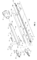
- An outer shaft member 60 defines an exterior surface of the elongated shaft 16 and supports movement of other components therethrough as described below.
- the outer shaft member 60 may be constructed from a flat stock piece of metal.
- a stamping, punching or similar metal-working process may be employed to initially generate a flat blank that includes an appropriate outer profile and any interior openings or features. Thereafter, the necessary folds, bends and curves, etc., may be formed by bending the flat blank with a press brake, or other suitable metal-working equipment.
- folds, bends and curves may be formed in metal components simultaneously with the outer profile and interior openings, or with the same equipment employed for forming the outer profile and interior openings.
- a reference to a stamping process may be understood to include the formation of a flat profile, as well as imparting any curves, rolls or bends, etc., to the relevant component.
- the outer shaft member 60 may be formed by folding the flat blank into a generally rectangular profile such that two opposing longitudinal edges of the flat blank meet at a longitudinal seam 62 (see FIG. 4 ).
- the longitudinal seam 62 may be joined by laser welding (or other suitable processes) the two opposing longitudinal edges together to form a continuous rectangular profile.
- the seam 62 may be generally straight as depicted, or alternatively, a box joint, a dovetail joint or other interfaces known in the metal-working arts may be defined along the seam 62.
- the outer shaft member 60 defines a clevis 64 at a distal end thereof for receiving the jaw members 30 and 32.
- Opposing vertical sidewalls 64a and 64b of the outer shaft member 60 extend distally of horizontal walls 64c and 64d and include respective bores 66a, 66b extending therethrough.
- the bores 66a, 66b frictionally support the pivot pin 44 and maintain an orientation of the pivot pin 44 with respect to the outer shaft member 60.
- the pivot pin 44 may be fastened to the outer shaft member 60 by laser or heat-based welding, adhesives, chemical bonding, or other suitable processes.
- a pair of tabs 66c are provided to couple the outer shaft member 60 to the rotation knob 28.
- the connection established between the outer shaft member 60 and the rotation knob is described below with reference to FIGS. 5 and 6 .
- the pivot pin 44 extends through a proximal portion of each of the jaw members 30, 32 to pivotally support the jaw members 30, 32 at the distal end of the outer shaft member 60.
- a proximal portion of each of the jaw members 30, 32 is configured as a "double flag” (alternately referred to as a "double flange”).
- the double flag configuration refers to the two laterally spaced parallel flanges or "flags" 30a, 30b and 32a, 32b respectively, extending proximally from a distal portion of the jaw members 30 and 32.
- a lateral cam slot 30c and a lateral pivot bore 30d extend through each of the flags 30a, 30b of the upper jaw member 30.
- a lateral cam slot 32c and a lateral pivot bore 32d extend through each of the flags 32a, 32b of the lower jaw member 32.
- the pivot bores 30d, 32d receive the pivot pin 44 in a slip-fit relation that permits the jaw members 30, 32 to pivot about the pivot pin 44 to move the end effector 14 between the open and closed configurations ( FIGS. 2A and 2B respectively).
- a distal portion of each of the jaw members 30, 32 extends distally of the outer shaft member 60.
- the distal portion of each of the jaw members 30, 32 may be curved to facilitate manipulation of tissue and to provide better "line of sight" for accessing organs and large tissue structures.
- the jaw members 30, 32 curve to the left from the perspective of a user.
- the end effector 14 may be rotated about the longitudinal axis A-A such that the jaw members 30, 32 curve to the right.
- end effector 220 may be rotated to a stable orientation where jaw members 222, 224 curve in an upward direction.
- a pair of wire guides 68 are provided to protect the wires 46a, 46b ( FIG. 4 )
- the wire guides 68 are positioned adjacent interior surfaces of the opposing vertical sidewalls 64a and 64b of the outer shaft member 60. Adhesives, screws or similar fastening mechanisms may be employed to affix the wire guides 68 such that position of the wire guides 68 may be maintained.
- wire guides 68 may be eliminated and structures may be incorporated into nearby components which may serve as wire guides.
- the wire guides 68 are generally flat and may be constructed of metal, a lubricious plastic such as polytetrafluoroethylene (PTFE) or similar material.
- the wire guides 68 may thus provide a bearing surface for the exterior surfaces of flags 32a and 32b of the lower jaw member 32 as the jaw members 30, 32 pivot about the pivot pin 44.
- the wire guides 68 include a longitudinal passageway 70 through which a respective one of the wires 46a, 46b ( FIG. 4 ) may extend to connect the sealing plates 48, 50 ( FIG. 2A ) to the electrosurgical generator 40 ( FIG. 1 ).
- the passageways 70 maintain the wires against the sidewalls 64a, 64b of the clevis 64 to discourage entanglement of the wires due to motion of the various components within the elongated shaft 16.
- a distal flare 72 is provided in the passageways 70 to provide clearance for the wires to move with the jaw members 30, 32 as the jaw members 30, 32 pivot.
- Holes 74 are provided in the wire guides 68 to permit passage of the pivot pin 44 therethrough, and slots 76 are provided to guide motion of a cam pin 92 as described below with continued reference to FIG. 3 .
- the slots 76 are optional and may be excluded from the wire guides 68 in some alternative embodiments where the cam pin 92 is sufficiently short.
- the holes 74 and the slots 76 are disposed on a central axis of the wire guides 68, and thus, two identical wire guides 68, oriented oppositely, may provide proper alignment with the holes 66a and 66b on outer shaft member 60.
- a jaw drive rod 80 is received within the outer shaft member 60 and is configured for longitudinal motion with respect to the outer shaft member 60.
- the jaw drive rod 80 is constructed from a flat, metal stock piece, and may be formed by a stamping process similar to the formation of the outer shaft member 60 as described above.
- the jaw drive rod 80 generally exhibits a U-shaped profile including sidewalls 82a, 82b and a u-shaped connector portion 82c.
- Horizontal flanges 84a and 84b protrude laterally from the respective sidewalls 82b and 82a and laterally support the jaw drive rod within the outer shaft member 60.
- the distal portion 86 of the jaw drive rod 80 includes a round hole 90 extending through the sidewalls 82a, 82b for receiving the cam pin 92.
- the cam pin 92 may be friction fit, welded or otherwise fastened within the hole 90 such that the cam pin 92 is fixedly coupled to the jaw drive rod 80 and protrudes laterally from each of the sidewalls 82a and 82b.
- a longitudinal slot 96 is defined through the sidewalls 82a, 82b. The longitudinal slot 96 provides clearance for the pivot pin 44, and thus, permits longitudinal reciprocation of the jaw drive rod 80 independent of the pivot pin 44.
- An overfold 98 is defined in the vicinity of the hole 90 and the slot 96. A portion of the sidewall 82b is folded toward the opposing sidewall 82a such that a portion of the jaw drive rod 80 exhibits a generally closed profile in the vicinity of the overfold 98. As described in greater detail below with reference to FIG. 4 , the overfold 98 permits the jaw drive rod 80 to serve as a knife guide to guide the motion of a knife 102.
- the proximal portion 88 of the jaw drive rod 80 includes a set of laterally protruding collar stops 88a, 88b and 88c, and a pair of laterally protruding spring stops 88d, 88e.
- the collar stops 88a, 88b, 88c engage a drive collar 184, and the spring stops 88d, 88e engage a spring keeper 192, which, as described below with reference to FIG. 18 , cooperate to operatively couple the jaw drive shaft 80 to the movable handle 22.
- the outer shaft member 60 is secured to the rotation knob 28 by the engagement of the tabs 66c on the outer shaft member 60 with the rotation knob 28 (see also, FIG. 6 ).
- the jaw drive rod 80 is positioned within the outer shaft member 60 such that the horizontal flanges 84a and 84b of the jaw drive rod 80 abut the sidewalls 64a and 64b of the outer shaft member 60.
- the wire guides 68 are positioned between the sidewalls 64a and 64b of the outer shaft member 60 and the flags 32a, 32b of the lower jaw member 32, thus, providing lateral support to the lower jaw member 32.
- the flags 30a, 30b of the upper jaw member 30 are disposed laterally within the flags 32a, 32b of the of the lower jaw member 32.
- This arrangement of flags 30a, 30b laterally within the flags 32a, 32b may be described as a “nestled” arrangement. Other arrangements are contemplated such as the "offset" arrangement described below with reference to FIG. 15 .
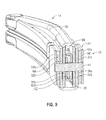
- the knife 102 is centrally disposed within the jaw drive shaft 80.
- the sidewalls 82a, 82b of the jaw drive shaft 80 provide lateral support to the knife 102, and vertical support is provided by the u-shaped connector portion 82c and the over-fold 98.
- the knife 102 is substantially surrounded at its distal end by the jaw drive shaft 80 on four lateral sides, and by substantially surrounding the knife 102 at its distal end, the jaw drive shaft 80 constrains the motion of the knife 102 in the four lateral directions. Free motion of the knife 102 is permitted only in a longitudinal direction.
- the jaw drive shaft 80 serves as a knife guide by urging the knife 102 into a central position within the elongated shaft 16, and thus ensuring proper alignment of the knife 102 as the knife 102 reciprocates within knife channel 58 ( FIG. 2A ).
- the jaw drive rod 80 restricts movement of the knife 102 in two orthogonal lateral planes, e.g. a vertical and a horizontal plane.
- the jaw drive rod 80 may also serve to protect the knife 102 and other components from damage throughout the assembly of the elongated shaft 16 and jaw members 30, 32.
- a proximal end of the rotation knob 28 is configured to engage the housing 12.
- a circular groove 124 is defined around a circular boss 126 projecting proximally from the rotation knob 28.
- the circular groove 124 receives an inwardly projecting wall (not visible) of the housing 12 to maintain the rotation knob 28 against the distal end of the housing 12.
- the circular groove 124 guides the rotational motion of the rotation knob 28 about the longitudinal axis A-A ( FIG. 1 ).
- Two radially opposite positions are defined wherein the rotational position of the rotation knob 28 is relatively stable. These two radially opposite positions correspond with two orientations of the end effector 14 ( FIG. 1 ) in which the jaw members 30, 32 curve to the right and to the left from the perspective of a user.
- the end effector 14 is coupled to the distal end of the elongated shaft 16 by the pivot pin 44.
- the pivot pin 44 is coupled to the sidewalls 64a and 64b of the clevis 64 defined at the distal end of the outer shaft member 60.
- the pivot pin 44 represents a longitudinally stationary reference for the longitudinal movements of jaw drive rod 80 and the knife 102.
- the pivot pin 44 extends through the wire guides 68, the flags 32a, 32b of the lower jaw member 32, the flags 30a and 30b of the upper jaw member 30, the sidewalls 82a, 82b of the jaw drive shaft 80, and the knife 102.
- the jaw members 30, 32 are free to pivot about the pivot pin 44, and the jaw actuation shaft 80 and the knife 102 are free to translate longitudinally around the pivot pin 44.
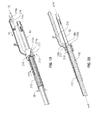
- the jaw drive rod is 80 is disposed in a distal position maintaining the end effector 14 in the open configuration. Since the jaw drive rod 80 is coupled to the cam pin 92, when the jaw drive rod 80 is in the distal position, the cam pin 92 is located in a distal position in cam slots 30c and 32c defined through the flags 30a, 30b, 23a, 32b of the jaw members 30, 32. Also, when the jaw drive rod 80 is in the distal position, a distal-most face 86a of the jaw drive rod 80 extends to a tissue receiving region 14a of the end effector 14. Thus, the jaw drive rod 80 provides a stop to prevent the entry of tissue into the elongated shaft 16.
- the jaw drive rod 80 may be drawn proximally relative to the pivot pin 44 (the stationary longitudinal reference) to move the end effector 14 to the closed configuration (see FIG. 2B ). Since the longitudinal position of the pivot pin 44 is fixed (by the outer shaft member 60, which is removed from view in FIG. 10 for clarity), and since the cam slots 30c, 32c are obliquely arranged with respect to the longitudinal axis A-A, proximal retraction of the cam pin 92 through the cam slots 30c, 32c induces the jaw members 30, 32 to pivot toward one another about the pivot pin 44. Conversely, when the end effector 14 is in the closed configuration, longitudinal translation of the jaw drive rod 80 in a distal direction induces the jaw members 30, 32 to pivot away from one another toward the open configuration.
- the knife 102 when the end effector 14 is in the closed configuration, the knife 102 is freely movable in a longitudinal direction within the jaw drive shaft 80.
- the slot 106 in the knife 102 extends around the both the pivot pin 44 and the cam pin 92, and thus the pins 44, 92 do not interfere with the reciprocal motion of the knife 102.
- the blade 56 at the distal-most end of the knife 102 is centrally aligned by the distal-most end of the jaw drive rod 80 that includes the fold-over 98.
- the blade 104 readily enters the knife channel 58 defined in the jaw members 30, 32.
- the portion of the knife 102 extending distally from the jaw drive rod 80 is free to bend and, thus, the blade 104 follows the curvature of the knife channel 58 through the jaw members 30, 32 as the knife 102 reciprocates longitudinally.
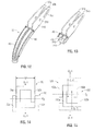
- the lower jaw member 32 is constructed of three major components. These components include a double-flag jaw insert 140, an insulator 142 and the sealing plate 48. In some alternative embodiments, as described below with reference to FIG. 22 , for example, a jaw member 224 may be provided that is constructed of major components arranged to provide unique advantages.
- the flags 32a, 32b of the jaw member 32 define a proximal portion of the double-flag jaw insert 140, and a generally u-shaped channel 144 extends distally to support the tissue engaging portion of the jaw member 32.
- the double-flag jaw insert 140 includes various planar surfaces, and may be constructed as a sheet metal component formed by a stamping process as described above. In such a stamping process, the cam slots 32c and pivot holes 32d may be punched into a flat blank, and subsequently the blank may be bent to form the flags 32a, 32b and the u-shaped channel 144. A lateral bend may also be applied to the jaw insert 140 to accommodate the curvature of the jaw member 32.
- the insulator 142 may be constructed of an electrically isolative plastic such as a polycarbonate (PC), acrylonitrile butadiene styrene (ABS), or a blend (PC/ABS) thereof.
- the electrically isolative plastic may be overmolded onto the jaw insert 140 in a single-shot injection molding process.
- Various features may be molded into the insulator 142 that facilitate the attachment of the sealing plate 48 to the insert 140. For example, tabs may be provided that permit a snap-fit attachment of the sealing plate 48, or ridges may formed that permit ultrasonic welding of the sealing plate onto the insulator 142.
- the sealing plate 50 may be constructed of an electrically conductive metal, and may be stamped from a flat sheet stock.
- the flags 30a, 30b of the upper jaw member 30 are depicted schematically in a nestled configuration with respect to the flags 32a, 32b of the lower jaw member 32.
- the proximal portion of the upper jaw member 30 is narrower than the proximal portion of the lower jaw member 32, and thus, a lateral spacing "S" between the flags 32a, 32b is sufficient to permit the flags 30a and 30b to be positioned therebetween.
- one flag 150a of the upper jaw member 150 is positioned on a laterally exterior side of the corresponding flag 152a of the lower jaw member 152, and the other flag 150b of the upper jaw member 150 is positioned on a laterally interior side of the corresponding flag 152b of the lower jaw member 152.
- a centerline "CL - 2" of the proximal portion of the upper jaw member 150 is laterally offset with respect to a centerline "CL - 3" of the lower jaw member 152.
- a distal, tissue engaging portion (depicted in phantom) of the jaw members 150, 152 is generally straight, e.g., without the lateral curve of jaw members 30, 32 (see, e.g., FIG. 2B )
- the offset configuration permits the jaws 150 and 152 to be constructed as substantially identical components.
- the straight distal portions of the jaw members 150, 152 may be aligned along a common centerline "CL-4" although proximal portions of the jaw members 150, 152 are aligned along their respective centerlines "CL - 2" and "CL - 3.”
- a forceps with identically configured jaw members 150, 152 may be relatively economical to produce.
- the actuation mechanism 160 employs a pair of stamped lever links 162, 164 for opening and closing a pair of jaw members 166, 168.
- An upper jaw member 166 includes a proximal flange 166a pivotally coupled to a lower lever link 162 about pivot axis "P1.”
- a lower jaw member 168 includes proximal flanges 168a pivotally coupled to an upper lever link 164 about pivot axis "P2.”
- Each of the proximal flanges 166a and 168a may also be constructed as stamped metal components as described above.
- the reciprocating drive rod 170 is movable in a distal longitudinal direction as indicated by arrow "D1" and a proximal longitudinal direction, as indicated by arrow "D2.” Since the longitudinal position of the pivot pin 172 is fixed, longitudinal movement of the reciprocating drive rod 170 induces the link 162 to pivot simultaneously about axes "P1" and “P3,” and induces link 164 to pivot simultaneously about axes "P2" and “P4.” This simultaneous pivoting of the links 162, 164 induces the jaw members 166, 168 to pivot about the axis "P5" between the closed configuration depicted and an open configuration (not shown).
- the double flag jaw members 166, 168 include proximal flanges 166a, 168a arranged in a nestled configuration (see FIG. 14 ).
- the upper link 164 may also be characterized as “nestled,” or disposed laterally between, the flags of proximal flange 168a of the lower jaw member 168.
- the proximal flange 166a of the upper jaw member 166 is "nestled" within the lower lever link 162.
- Each of the pivot links 162, 164 and the proximal flanges 166a, 168a include a generally u-shaped cross section to permit the pivot links 162, 164 to interleave with the proximal flanges 166a, 168a in this manner.
- This configuration provides a central channel 174 through which a knife or other centrally disposed drive component (not shown) may extend.
- the actuation mechanism 160 allows the jaw members 166, 168 to open or separate from one another to a greater degree than an actuation mechanism for opening similarly sized jaw members employing a simple cam slot (see, e.g., FIG. 10 ).
- the actuation mechanism 160 also provides a tactile feel that some operators may prefer.
- the stamped lever links 162, 164 and proximal flanges 166a, 168a provide a relatively strong actuation mechanism 160, which permits the jaw members 166, 168 to apply a relatively large force to tissue captured therebetween.
- the movable handle 22 may be manipulated to impart longitudinal motion to the jaw drive rod 80 ( FIG. 10 ), and knife trigger 26 may be manipulated to impart longitudinal motion to the knife 102 ( FIG. 11 ).
- longitudinal motion of the jaw drive rod 80 serves to move the end effector 14 between the open configuration of FIG. 2A and the closed configuration of FIG. 2B
- longitudinal motion of the knife 102 serves to move knife blade 56 through knife channel 58 ( FIG. 2A ).
- the movable handle 22 is operatively coupled to the jaw drive rod 80 by a connection mechanism 176.
- the connection mechanism 176 includes a clevis 178 defined at an upper end of the movable handle 22.
- the clevis 178 is pivotally supported on the right housing half 12a by a pivot boss 180.
- a second complementary pivot boss 180 (not shown) is provided on the left housing half 12b ( FIG. 1 ) to support the clevis 178.
- Each of two upper flanges 178a and 178b of the clevis 178 include rounded drive surfaces 182a and 182b thereon for engaging respective rims 184a and 184b of a drive collar 184 ( FIG. 18 ).
- the drive surfaces 182a, 182b are arranged along the longitudinal axis A-A such that pivotal motions of the movable handle 22 about the pivot bosses 180 induce corresponding longitudinal motions of the drive collar 184 along the longitudinal axis A-A.
- a distal longitudinal motion may be imparted to the connection mechanism 176 by pushing the distal rim 184a of the drive collar 184 with the movable handle 22 ( FIG. 17 ) as indicated by arrow D3.
- the distal rim 184a engages the collar stops 88a ( FIG. 3 ), 88b and 88c.
- the distal longitudinal motion of the drive collar 184 will be transmitted directly to the jaw drive rod 80 to induce a corresponding distal motion of the jaw drive rod 80.
- a proximal longitudinal motion may be imparted to the connection mechanism 176 by pushing the proximal rim 184b of the drive collar 184 with the movable handle 22 ( FIG. 17 ) as indicated by arrow D4.
- the proximal rim 184b engages a compression spring 188, which is constrained between the proximal rim 184b and a spring keeper 192.
- the spring keeper 192 engages the spring stops 88d ( FIG. 3 ) and 88e of the jaw drive rod 80.
- the spring 188 When compressed, the spring 188 imparts additional force to the jaw drive rod 80, which results in additional closure force applied to tissue captured between the jaw members 30, 32 (see FIG. 2B ).
- the spring 188 also serves to bias the jaw members 30, 32 and the movable handle 22 to the open configuration.
- a rotation spacer 196 is supported at the proximal end of the jaw drive rod 80.
- the rotation spacer 196 includes an interior passageway (not shown) that receives the irregular cross-section of the jaw drive rod 80.
- An outer surface of the rotation spacer 196 is generally cylindrical, and thus, the rotation spacer 196 may support the proximal end of the jaw drive rod 80 within the housing 12 (see FIG. 17 ) through rotation of the elongated shaft 80 about the longitudinal axis A-A, e.g., rotation induced by rotation of the rotation knob 28 ( FIG. 17 ).
- the knife carriage 210 is longitudinally movable over the jaw drive rod 80 independently of the motion of the jaw drive rod 80.
- the jaw drive rod 80 may be regarded as a stationary reference for the movement of the knife carriage 210.
- the knife carriage 210 includes a sleeve 212, a knife arm 216, and a cap 218.
- the knife arm 216 includes a pivot boss 216a, about which the link 208 (see FIG. 21C ) is coupled to knife arm 216. As described below with reference to FIG. 21C , the link 208 imparts longitudinal movement to the knife carriage 210 in a distal direction of arrow A9. Guide arms 216b protrude laterally from the proximal end of the knife arm 216, and engage a respective guide slot 12c (shown schematically in FIG. 19 and visible in FIG. 21C ) defined in the housing 12 to guide the longitudinal motion of the knife carriage 210.
- the knife carriage 210 abuts a spring 219, which is compressed against the rotation knob 28 (shown schematically in FIG. 19 ) when the knife carriage 210 translates in the direction of arrow A9.
- the spring 219 biases the knife carriage 210 in a proximal direction to a proximal position along the jaw drive rod 80.
- a sequence of motions may be initiated by moving the movable handle 22 to induce motion in the jaw drive mechanism in order to close the jaws 30, 32, and by moving the trigger 26 to induce motion in the knife actuation mechanism in order to translate the bade 56 through the jaws 30, 32.
- both the moveable handle 22 and the knife trigger 26 are in a distal or un-actuated position as depicted in FIG. 21A .
- This arrangement of the moveable handle 22 and trigger 26 sustains the end effector 14 in the open configuration ( FIG.
- the movable handle 22 may be moved from the distal position of FIG. 21A to the intermediate position depicted in 21B to move the jaw members 30, 32 to the closed configuration ( FIG. 2B ).
- the drive surface 182b engages the proximal rim 184b of the drive collar 184.
- the drive collar 184, the spring 188 and the spring keeper 192 are all driven proximally against the spring stops 88d and 88e of the jaw drive rod 80, and thus, the jaw drive rod 80 is driven proximally in the direction of arrow M2.
- proximal movement of the jaw drive rod 80 serves to draw the cam pin 92 proximally though the cam slots 30c, 32c of the jaw members 30, 32 and thus pivot the jaw members 30, 32 toward one another.
- the jaw actuation mechanism "bottoms out” and further proximal movement of the cam pin 92 and the jaw drive rod 80 is prohibited.
- a flange 22a on the moveable handle 22 is received in a railway 20a supported within the stationary handle 20.
- the railway 20a serves to temporarily lock the movable handle 22 in the proximal position against the bias of the spring 188, which biases the movable handle 22 from the proximal position of FIG. 21C to the intermediate position of FIG. 21B .
- the railway 20a permits the maintenance of pressure at the end effector 14 without actively maintaining pressure on the movable handle 22.
- the flange 22a may be released from the railway 20a by pivoting the movable handle 22 proximally and releasing the movable handle 22 to move under the influence of the spring 188.
- the knife trigger 26 When the movable handle 22 is in the actuated or proximal position, the knife trigger 26 may be selectively moved from the distal position of FIG. 21C to the proximal position of FIG. 21D to advance the knife blade 56 distally through the jaw members 30, 32.
- the knife trigger 26 may be pivoted in the direction of arrow M5, about pivot boss 202 to advance the flange 26b of the knife trigger 26 distally in the direction of arrow M6. Movement of the flange 26b induces the link 208 to pivot with respect to the flange 26b of the trigger 26, and with respect to the knife arm 216 such that the link 208 draws the knife carriage 210 distally in the direction of arrow M7.
- distal movement of the knife carriage 210 advances the knife blade 56 distally through the jaw members 30, 32.
- an alternate embodiment of an end effector 220 includes upper and lower jaw members 222 and 224 respectively, which are configured to facilitate blunt dissection of tissue.
- Each jaw member 222, 224 exhibits a scalloped distal end with a ledge 222a, 224a protruding distally from a less prominent portion 222b, 224b of the distal tip.
- the ledges 222a, 224a may be pressed into tissue to be dissected.
- the end effector 220 may then be moved to the open configuration to separate the jaw members 222, 224 and any tissue gripped by the ledges 222a, 224a.
- the ledges 222a, 224a may be constructed of an electrically isolative material, e.g., the insulator 230 as depicted in FIG. 23 .
- the upper jaw member 222 is constructed of three major components including a double-flag jaw insert 234, the insulator 230 and a sealing plate 238.
- the insulator 230 may molded onto a u-shaped channel 236 of the of the double-flag jaw insert 234 and the sealing plate 238 in a single-shot molding operation.
- the insulator 230 may completely surround the u-shaped channel 236, and may include various features such as the ledge 224a ( FIG. 22 ) at the distal end thereof, and a wire guide 240 at a proximal end thereof.
- the wire guide 240 is a portion of the insulator 230 that is molded to a lateral side of the double-flag jaw insert 234, and over the wire 46b that couples the sealing plate 238 to the electrosurgical generator 40 ( FIG. 1 ) as described above.
- the wire guide 240 includes a hole 244 to provide clearance for a pivot pin 44 ( FIG. 24 ), and is disposed on a single lateral side of the upper jaw member 222.
- Lower jaw member 224 ( FIG. 22 ) may include a similar wire guide (not shown), which may be positioned on the opposing lateral side when the upper and lower jaw members 222, 224 are assembled to an outer shaft member 250 in an "offset" arrangement as depicted in FIG. 24 .
- the wire guide 240 may thus protect the wire 46b from abrasion from the outer shaft member 250 as the upper jaw member 222 pivots about pivot pin 44.
- a rotation knob 260 is constructed of two distinct components 262 and 264.
- An exterior component 262 provides gripping surfaces 268 which may be engaged by an operator in use.
- the exterior component 262 generally exhibits a thin wall construction to facilitate molding from a plastic or similar material.
- Inner wall portions 270 are provided to engage an inner component 264 of the rotation knob 260 in a snap-fit manner.
- the inner component 264 includes a distal engagement portion 272 for coupling the rotation knob 260 to the outer shaft member 250 (see FIG. 27 ), and a circular boss 276 extending proximally therefrom.
- the circular boss 276 includes radially spaced detents 278 projecting radially from an outer circumference thereof and a proximal extension 280 protruding longitudinally therefrom.
- the detents 278 and proximal extension 280 define the rotational limits of the rotation knob 260 as described below with reference to FIG. 28 .
- the outer shaft member 250 may be coupled to the rotation knob 260 in a snap-fit manner.
- the outer shaft member 250 includes a pair of rectangular openings 284 extending through vertical sidewalls 250a, 250b near a proximal end thereof.
- the rectangular openings 284 provide flexibility to the proximal end of the outer shaft member 250 such that a pair of latches 288 at a proximal end of the sidewalls 250a, 250b may be installed into the distal engagement portion 272 of the interior component 264 of the rotation knob 260.
- the distal engagement portion 272 includes tapered walls 272a, 272b to urge the latches 288 laterally inward temporarily as the outer shaft member 250 is inserted longitudinally between the walls 272a, 272b. Once the latches 288 have been inserted proximally beyond the walls 272a, 272b, the latches 288 will snap into place as the resiliency of the outer shaft member 250 urges the latches laterally outward. The outer shaft member 250 may thus be operatively coupled to the rotation knob 260.
- the rotational motion of the rotation knob 260 is limited by its connection to a housing 302, which includes right and left housing halves 302a, 302b, respectively.
- a stop 304 projects laterally inward from housing half 302b and is positioned to engage the proximal extension 280 to prevent rotational motion of the rotation knob further than, in one embodiment, 180 degrees in either direction.
- a pair of the detents 278 extending from outer circumference of the rotation knob 260 engage a pair of cantilever arms 306 projecting from the housing half 302b. The engagement of the detents 278 with the cantilever arms 306 defines a relatively stable relation between the rotation knob 260 and the housing 302.
- the detents 278 are radially spaced by about 90 degrees such that at least three relatively stable positions may be defined within the extent of the rotation permitted by proximal extension 280 and the stop 304. These positions may correspond to a configuration wherein jaw members 222 and 224 ( FIG. 22 ) curve to the left, in an upward direction, and to right from the perspective of a user.
- the components for limiting the rotation of the rotation knob 260 are all defined on an interior of the housing 302, and thus, interference from foreign materials is limited.
- the outer shaft member 250, rotation knob 260 and the housing 302 define a longitudinal passage through which jaw drive rod 80, knife 102 and wire conduits 78a and 78b may extend.
- the rotation knob 260 may also include an interior shelf (not shown) against which spring 219 may be compressed (see FIG. 21D for a depiction of the spring 219 in a compressed state).
- a knife carriage 310 may be operatively coupled to the knife 102 by relative rotation of the knife carriage 310 with respect to the knife.
- the knife carriage 310 includes a single component (compare with knife carriage 210 described above with reference to FIG. 19 , which includes both a cap 218 and a sleeve 212 for capturing the knife 102).
- An opening 312 in the knife carriage 310 receives the proximal tabs 108a, 108b of the knife 102.
- Rotation of the knife carriage 310 in the direction of arrow Q1 captures the proximal tabs 108a, 108b against a proximal ledge of the knife carriage.
- longitudinal motion may be transmitted between the knife carriage 310 and the knife 102.
Abstract
Description
- The present disclosure relates generally to the field of surgical instruments. In particular, the disclosure relates to an endoscopic electrosurgical forceps that is economical to manufacture and is capable of sealing and cutting relatively large tissue structures.
- Instruments such as electrosurgical forceps are commonly used in open and endoscopic surgical procedures to coagulate, cauterize and seal tissue. Such forceps typically include a pair of jaws that can be controlled by a surgeon to grasp targeted tissue, such as, e.g., a blood vessel. The jaws may be approximated to apply a mechanical clamping force to the tissue, and are associated with at least one electrode to permit the delivery of electrosurgical energy to the tissue. The combination of the mechanical clamping force and the electrosurgical energy has been demonstrated to join adjacent layers of tissue captured between the jaws. When the adjacent layers of tissue include the walls of a blood vessel, sealing the tissue may result in hemostasis, which may facilitate the transection of the sealed tissue. A detailed discussion of the use of an electrosurgical forceps may be found in
U.S. Patent No 7,255,697 to Dycus et al. - A bipolar electrosurgical forceps typically includes opposed electrodes disposed on clamping faces of the jaws. The electrodes are charged to opposite electrical potentials such that an electrosurgical current may be selectively transferred through tissue grasped between the electrodes. To effect a proper seal, particularly in relatively large vessels, two predominant mechanical parameters must be accurately controlled; the pressure applied to the vessel, and the gap distance established between the electrodes.
- Both the pressure and gap distance influence the effectiveness of the resultant tissue seal. If an adequate gap distance is not maintained, there is a possibility that the opposed electrodes will contact one another, which may cause a short circuit and prevent energy from being transferred through the tissue. Also, if too low a force is applied the tissue may have a tendency to move before an adequate seal can be generated. The thickness of a typical effective tissue seal is optimally between about 0.001 and about 0.006 inches. Below this range, the seal may shred or tear and above this range the vessel walls may not be effectively joined. Closure pressures for sealing large tissue structures preferably fall within the range of about 3kg/cm2 to about 16 kg/cm2.
- The present disclosure describes a surgical instrument for treating tissue that is economical to manufacture and is capable of sealing and cutting relatively large tissue structures. The surgical instrument includes a housing and an elongated shaft extending distally therefrom. The elongated shaft includes a proximal portion coupled to the housing and a distal portion opposite the proximal portion, and defines a longitudinal axis. A drive rod extends at least partially through the elongated shaft, and is selectively movable in a longitudinal direction with respect to the elongated shaft. An end effector is supported by the distal portion of the elongated shaft, and is adapted for treating tissue. The end effector includes an upper jaw member pivotally coupled to the distal portion of the elongated shaft about a pivot axis, and the upper jaw member includes a first pair of laterally spaced flanges. The end effector also includes a lower jaw member pivotally coupled to the distal portion of the elongated shaft about the pivot axis, and the lower jaw member includes a second pair of laterally spaced flanges. The first and second pairs of flanges of the jaw members are arranged in an offset configuration such that one flange of the upper jaw member is positioned on a laterally exterior side of a corresponding flange of the lower jaw member, and the other flange of the upper jaw member is positioned on a laterally interior side of the other flange of the lower jaw member. Alternatively, the laterally spaced flanges of the jaw members may be arranged in a nestled configuration wherein both of the flanges of one of the jaw members are arranged within a laterally interior side of the laterally spaced flanges of the other of the jaw members. A camming mechanism or some other cooperative arrangement is defined between some or all of the flanges and the drive rod such that longitudinal movement of the drive rod causes the jaw members to move between open and closed positions.
- The upper and lower jaw members may be constructed as substantially identical components positioned in a laterally offset manner with respect to one another. Each of the flanges may extend proximally from a tissue engaging portion of the jaw members, and the tissue engaging portions may be substantially curved. The curvature may be in a left or right direction relative to the longitudinal axis with respect to the jaw members opening and closing in up and down directions. The pivot axis may extends through each of the flanges in a direction substantially transverse to the longitudinal axis.
- The jaw members may each be formed from a metal sheet shaped to define the proximal flanges and a support portion for supporting a tissue engaging portion of the jaw member. The support portion may be shaped to form a U-shaped channel.
- The drive rod may extend through the jaw members on a laterally interior side of each of the flanges, and the drive rod may exhibit a generally u-shaped profile. The surgical instrument may further include a knife selectively movable in a longitudinal direction with respect to the drive rod, and the knife may be supported within the u-shaped profile such that the drive rod provides restricts lateral movement of the knife in a first lateral plane. The drive rod may also include an overfold disposed opposite a u-shaped connector portion of the drive rod such that the knife is substantially surrounded on four lateral sides, and such that the overfold and the u-shaped connector portion restrict movement of the knife in a second lateral plane that is orthogonal to the first lateral plane.
- In an embodiment, the drive rod includes opposed sidewalls disposed on either side and constraining a knife having a flat profile. A lower side wall connector portion may be provided for vertically supporting the knife, the connector portion extending between the sidewalls. In an embodiment, at least one (upper) horizontal flange extends form the or a respective sidewall to laterally support the drive rod within the elongated shaft. In an embodiment, the respective horizontal flanges project from respective sidewalls of the drive rod for abutting opposed sides of an interior of the elongated shaft to laterally guide the drive rod. The at least one flange may be provided along a part of the drive rod. A distal end portion of the drive rod may include a fold over to vertically constrain the knife in combination with the connector portion. The drive rod is shaped to envelope and guide the flat knife from at least three sides from a proximal end of the drive rod to a distal end.
- In an embodiment, the drive rod is formed by shaping a metal blank.
- In an embodiment, the instrument comprises at least one wire conduit into which one or more wires has been fed during assembly to electrosurgically connect the end effector to an electrosurgical energy source. The conduit may be disposed under the at least one flange of the drive rod and adjacent a sidewall of the drive rod. In the case of there being conduits, the conduits may be disposed outside opposed sidewalls of the drive rod and under opposed lateral flanges of the drive rod.
- The jaw member may be adapted for electrosurgically treating tissue and may include electrical wires extending proximally therefrom for facilitating connection of the respective jaw members to a source of electrosurgical energy. At least one of the flanges of each of the jaw members may include an electrically isolative wire guide disposed on a lateral side thereof, wherein the electrical wire of the respective jaw member extends through the wire guide. The wire guides may be constructed of an electrically isolative plastic molded onto the respective flanges.
- According to another aspect of the disclosure a surgical instrument includes a housing and an elongated shaft extending therefrom. The elongated shaft includes a proximal portion coupled to the housing and a distal portion opposite the proximal portion and defining a longitudinal axis. An end effector is supported by the distal portion of the elongated shaft. The end effector is adapted for treating tissue and includes first and second jaw members pivotally coupled to one another to move between open and closed configurations. Each of the jaw members includes a pair of laterally spaced flanges, and each of the flanges includes a camming surface thereon. A knife extends at least partially through the elongated shaft and is selectively movable in a longitudinal direction between the flanges of the jaw members. A blade of the knife is extendable into a tissue contacting portion of the jaw members. A drive rod extends at least partially through the elongated shaft and is selectively movable in a longitudinal direction with respect to the knife and with respect to the elongated shaft in response to manipulation of the housing. The drive rod carries a cam pin positioned to engage the camming surface of each of the flanges to induce the jaw members to move between the open and closed configurations. The drive rod substantially surrounds the knife on four lateral sides to restrict motion of the knife in at least two orthogonal planes.
- The laterally spaced flanges of the jaw members may be arranged in a nestled configuration wherein both of the flanges of one of the jaw members are arranged within a laterally interior side of the laterally spaced flanges of the other of the jaw members. The knife may be constructed of a substantially flat piece of metal, and the drive rod may be constructed of metal folded to exhibit a generally u-shaped profile extending around the four lateral sides of the knife. A distal-most end of the drive rod may extend around the four lateral sides of the knife and a proximal portion of the drive rod may extend around fewer than four lateral sides of the knife.
- In an embodiment, the elongated shaft exhibits a generally rectangular profile,
- The accompanying drawings, which are incorporated in and constitute a part of this specification, illustrate embodiments of the present disclosure and, together with the detailed description of the embodiments given below, serve to explain the principles of the disclosure.
-
FIG. 1 is a perspective view of an electrosurgical forceps according to an embodiment of the present disclosure including a housing, an elongated shaft, and an end effector; -
FIG. 2A is an enlarged perspective view of the end effector ofFIG. 1 depicted with a pair of jaw members in an open configuration; -
FIG. 2B is an enlarged perspective view of the end effector ofFIG. 1 depicted with the pair of jaw members in a closed configuration; -
FIG. 3 is a perspective view of the end effector and elongated shaft ofFIG. 1 with parts separated; -
FIG. 4 is cross-sectional view of the elongated shaft ifFIG. 1 taken through a plane that extends through an interface between the elongated shaft and a rotation knob, facing a proximal end of the jaw members; -
FIG. 5 is a proximally-facing perspective view of a rotation knob depicting a cavity for receiving an the elongated shaft ofFIG. 1 ; -
FIG. 6 is a cross-sectional, perspective view of the rotation knob ofFIG. 5 assembled to an outer shaft member of the elongated shaft ofFIG. 1 ; -
FIG. 7 is a distally-facing perspective view of the rotation knob ofFIG. 5 depicting a groove for receiving a portion of the housing ofFIG. 1 ; -
FIG. 8 is a perspective view of the rotation knob ofFIG. 5 assembled to the housing ofFIG. 1 ; -
FIG. 9 is a cross-sectional, perspective view of the end effector assembled with the elongated shaft ofFIG. 1 ; -
FIG. 10 is a partial, perspective view of a distal portion of a jaw actuation mechanism of the end effector ofFIG. 1 ; -
FIG. 11 is a partial, perspective view of distal portion of a knife actuation mechanism of the end effector ofFIG. 1 ; -
FIG. 12 is a perspective view of a lower jaw member of the end effector ofFIG. 1 depicting a double flange at a proximal end thereof; -
FIG. 13 cross-sectional, perspective view of the lower jaw member ofFIG. 12 ; -
FIG. 14 is a schematic view of the nestled arrangement of the double flange ofFIG. 12 with a double flange of an upper jaw member; -
FIG. 15 is a schematic view of an alternative offset arrangement of double flanges of an alternate pair of jaw members; -
FIG. 16 is a partial, perspective view of an alternate embodiment of a jaw actuation mechanism depicting an alternate pair of jaw members with a nestled arrangement of double flanges coupled to an reciprocating actuation rod by stamped links; -
FIG. 17 is a perspective view of a proximal portion of the instrument ofFIG. 1 with a portion of the housing removed revealing internal components; -
FIG. 18 is a partial, side view of a proximal portion of the jaw actuation mechanism ofFIG. 10 depicting a connection between the handle and the jaw drive rod mechanism for imparting longitudinal movement to the jaw drive rod; -
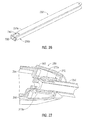
FIG. 19 is a perspective view of a proximal portion of the knife actuation mechanism ofFIG. 11 ; and -
FIG. 20 is a cross-sectional, perspective view of the knife actuation mechanism ofFIG. 19 . -
FIG. 21A is a side view of the proximal portion of the instrument ofFIG. 17 depicting a movable handle in a separated position with respect to a stationary handle, which corresponds to the open configuration of the end effector depicted inFIG. 2A , and a knife trigger in a separated configuration with respect to the stationary handle, which corresponds to an un-actuated or proximal configuration of a knife with respect to the jaw members; -
FIG. 21B is a side view of the proximal portion of the instrument ofFIG. 17 depicting the movable handle in an intermediate position with respect to the stationary handle, which corresponds to a first closed configuration of the end effector wherein the jaw members encounter one another; -
FIG. 21C is a side view of the proximal portion of the instrument ofFIG. 17 depicting the movable handle in an approximated configuration with respect to the stationary handle, which corresponds to a second closed configuration of the end effector wherein the jaw members apply an appropriate pressure to generate a tissue seal; -
FIG. 21D is a side view of the proximal portion of the instrument ofFIG. 17 depicting the knife trigger in an actuated configuration, which corresponds to an actuated or distal position of the knife with respect to the jaw members; -
FIG. 22 is a perspective view of an alternate embodiment of an end effector including upper and lower jaw members with scalloped distal ends; -
FIG. 23 is a cross-sectional, perspective view of an alternate embodiment of the lower jaw member of the end effector ofFIG. 22 ; -
FIG. 24 is a perspective view of the end effector ofFIG. 22 coupled to an outer shaft member, illustrating a wire guide incorporated into a proximal portion of the upper and lower jaw members; -
FIG. 25 is an exploded perspective view of an alternate embodiment of a rotation knob constructed of two distinct components; -
FIG. 26 is a perspective view of an alternate embodiment of an outer shaft member for connection with the rotation knob ofFIG. 25 ; -
FIG. 27 is a cross-sectional, perspective view of the rotation knob ofFIG. 25 assembled to the outer shaft member ofFIG. 26 ; -
FIG. 28 is cross sectional, perspective view the rotation knob ofFIG. 25 coupled to a alternate embodiment of a housing, illustrating stop features and detent arms for defining a "jaws up" configuration in addition to a jaws right and jaws left configuration; and -
FIG. 29 is an alternate embodiment of a jaw drive mechanism including single-component a knife arm configured for connection to the knife ofFIG. 3 without additional fasteners. - The present disclosure relates to an electrosurgical apparatus and methods for performing electrosurgical procedures. More particularly, the present disclosure relates to electrosurgically sealing tissue. As is traditional, the term "distal" refers herein to an end of the apparatus that is farther from an operator, and the term "proximal" refers herein to the end of the
forceps 10 which is closer to the operator. - Referring initially to
FIG. 1 , an embodiment of anelectrosurgical forceps 10 generally includes ahousing 12 that supports various actuators thereon for remotely controlling anend effector 14 through anelongated shaft 16. Although this configuration is typically associated with instruments for use in laparoscopic or endoscopic surgical procedures, various aspects of the present disclosure may be practiced with traditional open instruments and in connection with endoluminal procedures as well. - The
housing 12 is constructed of aleft housing half 12a and aright housing half 12b. The left and right designation of thehousing halves forceps 10. Thehousing halves - To mechanically control the
end effector 14, thehousing 12 supports astationary handle 20, amovable handle 22, atrigger 26 androtation knob 28. Themovable handle 22 is operable to move theend effector 14 between an open configuration (FIG. 2A ) wherein a pair ofopposed jaw members FIG. 2B ) wherein thejaw members movable handle 22 with thestationary handle 20 serves to move theend effector 14 to the closed confguration and separation of themovable handle 22 from thestationary handle 20 serves to move theend effector 14 open configuration. Thetrigger 26 is operable to extend and retract a knife blade 56 (seeFIG. 2A ) through theend effector 14 when theend effector 14 is in the closed configuration. Therotation knob 28 serves to rotate theelongated shaft 16 and theend effector 14 about a longitudinal axis A-A extending through the forceps. - To electrically control the
end effector 14, thehousing 12 supports aswitch 36 thereon, which is operable by the user to initiate and terminate the delivery of electrosurgical energy to theend effector 14. Theswitch 36 is in electrical communication with a source of electrosurgical energy such aselectrosurgical generator 40. Thegenerator 40 may include devices such as the LIGASURE® Vessel Sealing Generator and the Force Triad® Generator as sold by Covidien. Acable 42 extends between thehousing 12 and thegenerator 40 and may include a connector (not shown) thereon such that theforceps 10 may be selectively coupled and decoupled electrically from thegenerator 40. In other embodiments (not shown) a battery powered instrument may be provided in which a generator and connector may be internal or integral to the instrument. - Referring now to
FIGS. 2A and 2B , theend effector 14 may be moved from the open configuration (FIG. 2A ) wherein tissue (not shown) may be received between thejaw members FIG. 2B ), wherein the tissue may be clamped and sealed.Upper jaw member 30 andlower jaw member 32 are mechanically coupled to theelongated shaft 16 about apivot pin 44. Theupper jaw member 30 is electrically coupled tocable 42, and thus to thegenerator 40, (seeFIG. 1 ) through awire 46b extending through theelongated shaft 16. Thelower jaw member 32 is also coupled to thegenerator 40 by anotherwire 46a (FIG. 4 ) extending through theelongated shaft 16. Thewires sealing plates upper jaw members plate 48 of thelower jaw member 32 opposes a sealingplate 50 of theupper jaw member 30, and, in some embodiments, the sealingplates generator 40. Thus, bipolar energy may be provided through theend effector 14. Alternatively, theend effector 14 may be configured for delivering monopolar energy to the tissue. In a monopolar configuration, theend effector 14 delivers electrosurgical energy from an active terminal, e.g. (+), while a return pad (not shown) is placed generally on a patient and provides a return path to the opposite terminal, e.g. (-), of thegenerator 40. - The
jaw members pivot pin 44 to move theend effector 14 to the closed configuration ofFIG. 2B wherein the sealingplates plates stop members 54 disposed on or adjacent the sealingplates stop members 54 contact opposing surfaces on the opposingjaw member plates stop members 54 are constructed of an electrically non-conductive plastic or other material molded onto thejaw members stop members 54 are constructed of a heat-resistant ceramic deposited onto thejaw members - Electrosurgical energy may be delivered to the tissue through the electrically
conductive seal plates knife blade 56 may be advanced through aknife channel 58 defined in thejaw members Knife blade 56 is depicted inFIG. 2A as extending from theelongated shaft 16 when theend effector 14 is in an open configuration. In some embodiments, a knife lockout is provided to prevent extension of theknife blade 56 into theknife channel 58 when theend effector 14 is in the open configuration, thus preventing accidental or premature transection of tissue. - Referring now to
FIG. 3 , theelongated shaft 16 includes various longitudinal components that operatively couple theend effector 14 to the various actuators supported by the housing 12 (FIG. 1 ). Anouter shaft member 60 defines an exterior surface of theelongated shaft 16 and supports movement of other components therethrough as described below. Theouter shaft member 60 may be constructed from a flat stock piece of metal. In constructing theouter shaft member 60, a stamping, punching or similar metal-working process may be employed to initially generate a flat blank that includes an appropriate outer profile and any interior openings or features. Thereafter, the necessary folds, bends and curves, etc., may be formed by bending the flat blank with a press brake, or other suitable metal-working equipment. In some instances, folds, bends and curves may be formed in metal components simultaneously with the outer profile and interior openings, or with the same equipment employed for forming the outer profile and interior openings. Thus, a reference to a stamping process may be understood to include the formation of a flat profile, as well as imparting any curves, rolls or bends, etc., to the relevant component. Theouter shaft member 60 may be formed by folding the flat blank into a generally rectangular profile such that two opposing longitudinal edges of the flat blank meet at a longitudinal seam 62 (seeFIG. 4 ). Thelongitudinal seam 62 may be joined by laser welding (or other suitable processes) the two opposing longitudinal edges together to form a continuous rectangular profile. Theseam 62 may be generally straight as depicted, or alternatively, a box joint, a dovetail joint or other interfaces known in the metal-working arts may be defined along theseam 62. - The
outer shaft member 60 defines aclevis 64 at a distal end thereof for receiving thejaw members vertical sidewalls outer shaft member 60 extend distally ofhorizontal walls respective bores 66a, 66b extending therethrough. Thebores 66a, 66b frictionally support thepivot pin 44 and maintain an orientation of thepivot pin 44 with respect to theouter shaft member 60. Alternatively or additionally, thepivot pin 44 may be fastened to theouter shaft member 60 by laser or heat-based welding, adhesives, chemical bonding, or other suitable processes. - At a proximal end of the
outer shaft member 60, a pair oftabs 66c (only one visible inFIG. 3 ) are provided to couple theouter shaft member 60 to therotation knob 28. The connection established between theouter shaft member 60 and the rotation knob is described below with reference toFIGS. 5 and 6 . - The
pivot pin 44 extends through a proximal portion of each of thejaw members jaw members outer shaft member 60. As described in greater detail below with reference toFIG. 12 , a proximal portion of each of thejaw members jaw members lateral cam slot 30c and a lateral pivot bore 30d extend through each of theflags upper jaw member 30. Similarly, alateral cam slot 32c and a lateral pivot bore 32d extend through each of theflags lower jaw member 32. The pivot bores 30d, 32d receive thepivot pin 44 in a slip-fit relation that permits thejaw members pivot pin 44 to move theend effector 14 between the open and closed configurations (FIGS. 2A and 2B respectively). - A distal portion of each of the
jaw members outer shaft member 60. The distal portion of each of thejaw members FIG. 3 , thejaw members FIG. 8 , for example, theend effector 14 may be rotated about the longitudinal axis A-A such that thejaw members FIG. 28 , for example, andend effector 220 may be rotated to a stable orientation wherejaw members - A pair of wire guides 68 are provided to protect the
wires FIG. 4 ) The wire guides 68 are positioned adjacent interior surfaces of the opposingvertical sidewalls outer shaft member 60. Adhesives, screws or similar fastening mechanisms may be employed to affix the wire guides 68 such that position of the wire guides 68 may be maintained. In some alternative embodiments, as described below with reference toFIG. 23 , wire guides 68 may be eliminated and structures may be incorporated into nearby components which may serve as wire guides. - The wire guides 68 are generally flat and may be constructed of metal, a lubricious plastic such as polytetrafluoroethylene (PTFE) or similar material. The wire guides 68 may thus provide a bearing surface for the exterior surfaces of
flags lower jaw member 32 as thejaw members pivot pin 44. The wire guides 68 include alongitudinal passageway 70 through which a respective one of thewires FIG. 4 ) may extend to connect the sealingplates 48, 50 (FIG. 2A ) to the electrosurgical generator 40 (FIG. 1 ). Thepassageways 70 maintain the wires against thesidewalls clevis 64 to discourage entanglement of the wires due to motion of the various components within theelongated shaft 16. Adistal flare 72 is provided in thepassageways 70 to provide clearance for the wires to move with thejaw members jaw members Holes 74 are provided in the wire guides 68 to permit passage of thepivot pin 44 therethrough, andslots 76 are provided to guide motion of acam pin 92 as described below with continued reference toFIG. 3 . Theslots 76 are optional and may be excluded from the wire guides 68 in some alternative embodiments where thecam pin 92 is sufficiently short. Theholes 74 and theslots 76 are disposed on a central axis of the wire guides 68, and thus, two identical wire guides 68, oriented oppositely, may provide proper alignment with theholes 66a and 66b onouter shaft member 60. - A pair of
wire conduits wires FIG. 4 ) proximally of the wire guides 68. Thewire conduits wires wire conduits wires - A
jaw drive rod 80 is received within theouter shaft member 60 and is configured for longitudinal motion with respect to theouter shaft member 60. Thejaw drive rod 80 is constructed from a flat, metal stock piece, and may be formed by a stamping process similar to the formation of theouter shaft member 60 as described above. Thejaw drive rod 80 generally exhibits a U-shaped profile including sidewalls 82a, 82b and au-shaped connector portion 82c.Horizontal flanges respective sidewalls outer shaft member 60. Adistal portion 86 of thejaw drive rod 80 is configured for receipt within theouter shaft member 60 and includes features for operatively coupling thejaw drive rod 80 to theend effector 14. Aproximal portion 88 of thejaw drive rod 80 is configured for receipt within the housing 12 (FIG. 1 ), and includes features for operatively coupling thejaw drive rod 80 to the actuators supported thereon, e.g. themovable handle 22. - The
distal portion 86 of thejaw drive rod 80 includes around hole 90 extending through thesidewalls cam pin 92. Thecam pin 92 may be friction fit, welded or otherwise fastened within thehole 90 such that thecam pin 92 is fixedly coupled to thejaw drive rod 80 and protrudes laterally from each of thesidewalls hole 90, alongitudinal slot 96 is defined through thesidewalls longitudinal slot 96 provides clearance for thepivot pin 44, and thus, permits longitudinal reciprocation of thejaw drive rod 80 independent of thepivot pin 44. - An
overfold 98 is defined in the vicinity of thehole 90 and theslot 96. A portion of thesidewall 82b is folded toward the opposingsidewall 82a such that a portion of thejaw drive rod 80 exhibits a generally closed profile in the vicinity of theoverfold 98. As described in greater detail below with reference toFIG. 4 , theoverfold 98 permits thejaw drive rod 80 to serve as a knife guide to guide the motion of aknife 102. - The
proximal portion 88 of thejaw drive rod 80 includes a set of laterally protruding collar stops 88a, 88b and 88c, and a pair of laterally protruding spring stops 88d, 88e. The collar stops 88a, 88b, 88c engage adrive collar 184, and the spring stops 88d, 88e engage aspring keeper 192, which, as described below with reference toFIG. 18 , cooperate to operatively couple thejaw drive shaft 80 to themovable handle 22. - The
knife 102 is a generally flat, metal component defining a profile that may be constructed by a stamping process as described above. Theknife 102 supports the sharpenedknife blade 56 at a distal-most end thereof. The sharp edge of theknife blade 56 may be applied to the distal end of theknife 102 subsequent to the stamping process that forms the profile. For example, various manufacturing techniques may be employed such as grinding, coining, electrochemical etching or other suitable manufacturing processes for forming sharpened edges. Alongitudinal slot 106 is defined with theknife 102 to provide clearance for thepivot pin 44 and thecam pin 92.Proximal tabs knife 102 and provide a mechanism for operatively coupling theknife 102 to thetrigger 26. The connection between theknife 102 and thetrigger 26 is described in detail below with reference toFIGS. 19 and 20 . - Referring now to
FIG. 4 , the various components of theelongated shaft 16 are depicted assembled to one another and to the upper andlower jaw members outer shaft member 60 is secured to therotation knob 28 by the engagement of thetabs 66c on theouter shaft member 60 with the rotation knob 28 (see also,FIG. 6 ). Thejaw drive rod 80 is positioned within theouter shaft member 60 such that thehorizontal flanges jaw drive rod 80 abut thesidewalls outer shaft member 60. The wire guides 68 are positioned between the sidewalls 64a and 64b of theouter shaft member 60 and theflags lower jaw member 32, thus, providing lateral support to thelower jaw member 32. Theflags upper jaw member 30 are disposed laterally within theflags lower jaw member 32. This arrangement offlags flags FIG. 15 . - The
knife 102 is centrally disposed within thejaw drive shaft 80. Thesidewalls jaw drive shaft 80 provide lateral support to theknife 102, and vertical support is provided by theu-shaped connector portion 82c and the over-fold 98. Theknife 102 is substantially surrounded at its distal end by thejaw drive shaft 80 on four lateral sides, and by substantially surrounding theknife 102 at its distal end, thejaw drive shaft 80 constrains the motion of theknife 102 in the four lateral directions. Free motion of theknife 102 is permitted only in a longitudinal direction. Thus, thejaw drive shaft 80 serves as a knife guide by urging theknife 102 into a central position within theelongated shaft 16, and thus ensuring proper alignment of theknife 102 as theknife 102 reciprocates within knife channel 58 (FIG. 2A ). By substantially surrounding theknife 102 at its distal end, thejaw drive rod 80 restricts movement of theknife 102 in two orthogonal lateral planes, e.g. a vertical and a horizontal plane. Thejaw drive rod 80 may also serve to protect theknife 102 and other components from damage throughout the assembly of theelongated shaft 16 andjaw members - Referring now to
FIGS. 5 and 6 , therotation knob 28 is configured as a single component. In some alternative embodiments, as described below with reference toFIG 25 , for example, arotation knob 260 may be provided that is constructed of multiple components affixed to one another. Therotation knob 28 includes a distal opening 112 defined therein for receiving theouter shaft member 60. The distal opening 112 is bounded bylateral walls outer shaft member 60. The distal opening 112 includes aninterior landing 114 for seating a proximal-most surface of theouter shaft member 60 and two lateral latch pockets 116 for receiving thetabs 66c of theouter shaft member 60. Thetabs 66c are flexible and project laterally outward in a distal direction such that the insertion of the proximal end of theouter shaft member 60 onto the distal opening 112 of therotation knob 28 induces the tabs to flex inwardly momentarily as thetabs 66c engagelateral walls tabs 66c thus lock theouter shaft member 60 to therotation knob 28. Due to the rectangular profile of theouter shaft member 60 and the opening 112, rotational motion imparted to therotation knob 28 about the longitudinal axis A-A (FIG. 1 ) is transferred to theouter shaft member 60. - A
passageway 120 is defined through therotation knob 28 to permit longitudinal motion of the jaw drive shaft 80 (FIG. 3 ) therethrough. Thepassageway 120 is shaped such that rotational motion imparted to therotation knob 28 is transferred to thejaw drive shaft 80. In one embodiment, acable clearance passageway 122 is also defined throughrotation knob 28 to permit passage of electrical cables (e.g., 46a, 46b,FIG. 4 ) that electrically couple the sealingplates 48, 50 (FIG. 2A ) to the electrosurgical generator 40 (FIG. 1 ). Rotational motion imparted to therotation knob 28 may thus impart rotational motion to each of the components of theelongated shaft 16, and to theend effector 14, which is coupled thereto. - Referring now to
FIGS. 7 and 8 , a proximal end of therotation knob 28 is configured to engage thehousing 12. Acircular groove 124 is defined around acircular boss 126 projecting proximally from therotation knob 28. Thecircular groove 124 receives an inwardly projecting wall (not visible) of thehousing 12 to maintain therotation knob 28 against the distal end of thehousing 12. Thecircular groove 124 guides the rotational motion of therotation knob 28 about the longitudinal axis A-A (FIG. 1 ). - The rotational motion of the
rotation knob 28 may be limited by astop boss 130 projecting distally from thehousing 12. Thestop boss 130 is positioned to engage rotation stops 134 on therotation knob 28 to prevent rotational motion of the rotation knob further than, for example, 180 degrees in either direction.Detents 136 project proximally from therotation knob 28 to engage a distal surface of thestop boss 130 prior to thestop boss 130 engaging the rotation stops. When therotation knob 28 is rotated to a position wherein thestop boss 130 is positioned between arotation stop 134 and adetent 136, the rotational position of therotation knob 28 is relatively stable, and may be releasably maintained until a sufficient force is supplied to move thedetents 136 over thestop boss 130. Two radially opposite positions are defined wherein the rotational position of therotation knob 28 is relatively stable. These two radially opposite positions correspond with two orientations of the end effector 14 (FIG. 1 ) in which thejaw members - Referring now to
FIG. 9 , theend effector 14 is coupled to the distal end of theelongated shaft 16 by thepivot pin 44. Thepivot pin 44 is coupled to thesidewalls clevis 64 defined at the distal end of theouter shaft member 60. Thus, thepivot pin 44 represents a longitudinally stationary reference for the longitudinal movements ofjaw drive rod 80 and theknife 102. Laterally inward of thesidewalls pivot pin 44 extends through the wire guides 68, theflags lower jaw member 32, theflags upper jaw member 30, thesidewalls jaw drive shaft 80, and theknife 102. Thejaw members pivot pin 44, and thejaw actuation shaft 80 and theknife 102 are free to translate longitudinally around thepivot pin 44. - Referring now to
FIG. 10 , the jaw drive rod is 80 is disposed in a distal position maintaining theend effector 14 in the open configuration. Since thejaw drive rod 80 is coupled to thecam pin 92, when thejaw drive rod 80 is in the distal position, thecam pin 92 is located in a distal position incam slots flags jaw members jaw drive rod 80 is in the distal position, adistal-most face 86a of thejaw drive rod 80 extends to atissue receiving region 14a of theend effector 14. Thus, thejaw drive rod 80 provides a stop to prevent the entry of tissue into theelongated shaft 16. - The
jaw drive rod 80 may be drawn proximally relative to the pivot pin 44 (the stationary longitudinal reference) to move theend effector 14 to the closed configuration (seeFIG. 2B ). Since the longitudinal position of thepivot pin 44 is fixed (by theouter shaft member 60, which is removed from view inFIG. 10 for clarity), and since thecam slots cam pin 92 through thecam slots jaw members pivot pin 44. Conversely, when theend effector 14 is in the closed configuration, longitudinal translation of thejaw drive rod 80 in a distal direction induces thejaw members - Referring now to
FIG. 11 , when theend effector 14 is in the closed configuration, theknife 102 is freely movable in a longitudinal direction within thejaw drive shaft 80. Theslot 106 in theknife 102 extends around the both thepivot pin 44 and thecam pin 92, and thus thepins knife 102. Theblade 56 at the distal-most end of theknife 102 is centrally aligned by the distal-most end of thejaw drive rod 80 that includes the fold-over 98. Properly aligned, the blade 104 readily enters theknife channel 58 defined in thejaw members knife 102 extending distally from thejaw drive rod 80 is free to bend and, thus, the blade 104 follows the curvature of theknife channel 58 through thejaw members knife 102 reciprocates longitudinally. - Referring now to
FIGS. 12 and 13 , thelower jaw member 32 is constructed of three major components. These components include a double-flag jaw insert 140, aninsulator 142 and the sealingplate 48. In some alternative embodiments, as described below with reference toFIG. 22 , for example, ajaw member 224 may be provided that is constructed of major components arranged to provide unique advantages. - The
flags jaw member 32 define a proximal portion of the double-flag jaw insert 140, and a generallyu-shaped channel 144 extends distally to support the tissue engaging portion of thejaw member 32. The double-flag jaw insert 140 includes various planar surfaces, and may be constructed as a sheet metal component formed by a stamping process as described above. In such a stamping process, thecam slots 32c andpivot holes 32d may be punched into a flat blank, and subsequently the blank may be bent to form theflags u-shaped channel 144. A lateral bend may also be applied to thejaw insert 140 to accommodate the curvature of thejaw member 32. - The
insulator 142 may be constructed of an electrically isolative plastic such as a polycarbonate (PC), acrylonitrile butadiene styrene (ABS), or a blend (PC/ABS) thereof. The electrically isolative plastic may be overmolded onto thejaw insert 140 in a single-shot injection molding process. Various features may be molded into theinsulator 142 that facilitate the attachment of the sealingplate 48 to theinsert 140. For example, tabs may be provided that permit a snap-fit attachment of the sealingplate 48, or ridges may formed that permit ultrasonic welding of the sealing plate onto theinsulator 142. The sealingplate 50 may be constructed of an electrically conductive metal, and may be stamped from a flat sheet stock. - Referring now to
FIG. 14 , theflags upper jaw member 30 are depicted schematically in a nestled configuration with respect to theflags lower jaw member 32. A. The proximal portion of theupper jaw member 30 is narrower than the proximal portion of thelower jaw member 32, and thus, a lateral spacing "S" between theflags flags flags lower jaw members lower jaw members - An alternative to the nestled configuration illustrated in
FIG. 14 is the offset configuration illustrated schematically inFIG. 15 . A proximal portion of double-flagupper jaw member 150 includesflags lower jaw member 152 includesflags upper jaw member 150. To provide an overlapping portion of theflags jaw members flag 150a of theupper jaw member 150 is positioned on a laterally exterior side of thecorresponding flag 152a of thelower jaw member 152, and theother flag 150b of theupper jaw member 150 is positioned on a laterally interior side of thecorresponding flag 152b of thelower jaw member 152. In the offset configuration, a centerline "CL - 2" of the proximal portion of theupper jaw member 150 is laterally offset with respect to a centerline "CL - 3" of thelower jaw member 152. - In embodiments where a distal, tissue engaging portion (depicted in phantom) of the
jaw members jaw members 30, 32 (see, e.g.,FIG. 2B ), the offset configuration permits thejaws jaw members jaw members jaw members - Referring now to
FIG. 16 , an alternate embodiment of anactuation mechanism 160 is depicted. Theactuation mechanism 160 employs a pair of stampedlever links jaw members upper jaw member 166 includes aproximal flange 166a pivotally coupled to alower lever link 162 about pivot axis "P1." Alower jaw member 168 includesproximal flanges 168a pivotally coupled to anupper lever link 164 about pivot axis "P2." Each of theproximal flanges reciprocating drive rod 170 about respective pivot axes "P3" and "P4" and each of theproximal flanges pivot pin 172, which is arranged about a pivot axis "P5." Thepivot pin 172 is coupled to an outer shaft member (not shown), and thus represents a fixed reference for the motion of the motion of theactuation mechanism 160. - The
reciprocating drive rod 170 is movable in a distal longitudinal direction as indicated by arrow "D1" and a proximal longitudinal direction, as indicated by arrow "D2." Since the longitudinal position of thepivot pin 172 is fixed, longitudinal movement of thereciprocating drive rod 170 induces thelink 162 to pivot simultaneously about axes "P1" and "P3," and induces link 164 to pivot simultaneously about axes "P2" and "P4." This simultaneous pivoting of thelinks jaw members - The double
flag jaw members proximal flanges FIG. 14 ). Theupper link 164 may also be characterized as "nestled," or disposed laterally between, the flags ofproximal flange 168a of thelower jaw member 168. Theproximal flange 166a of theupper jaw member 166 is "nestled" within thelower lever link 162. Each of the pivot links 162, 164 and theproximal flanges proximal flanges central channel 174 through which a knife or other centrally disposed drive component (not shown) may extend. - The
actuation mechanism 160 allows thejaw members FIG. 10 ). Theactuation mechanism 160 also provides a tactile feel that some operators may prefer. The stampedlever links proximal flanges strong actuation mechanism 160, which permits thejaw members - Referring now to
FIG. 17 , the connection of themovable handle 22 and theknife trigger 26 to the longitudinally movable components of theelongated shaft 16 is described. Themovable handle 22 may be manipulated to impart longitudinal motion to the jaw drive rod 80 (FIG. 10 ), andknife trigger 26 may be manipulated to impart longitudinal motion to the knife 102 (FIG. 11 ). As discussed above, longitudinal motion of thejaw drive rod 80 serves to move theend effector 14 between the open configuration ofFIG. 2A and the closed configuration ofFIG. 2B , and longitudinal motion of theknife 102 serves to moveknife blade 56 through knife channel 58 (FIG. 2A ). - The
movable handle 22 is operatively coupled to thejaw drive rod 80 by aconnection mechanism 176. Theconnection mechanism 176 includes aclevis 178 defined at an upper end of themovable handle 22. Theclevis 178 is pivotally supported on theright housing half 12a by apivot boss 180. A second complementary pivot boss 180 (not shown) is provided on theleft housing half 12b (FIG. 1 ) to support theclevis 178. Each of twoupper flanges clevis 178 includerounded drive surfaces respective rims FIG. 18 ). The drive surfaces 182a, 182b are arranged along the longitudinal axis A-A such that pivotal motions of themovable handle 22 about thepivot bosses 180 induce corresponding longitudinal motions of thedrive collar 184 along the longitudinal axis A-A. - Referring now to
FIG. 18 , a distal longitudinal motion may be imparted to theconnection mechanism 176 by pushing thedistal rim 184a of thedrive collar 184 with the movable handle 22 (FIG. 17 ) as indicated by arrow D3. Thedistal rim 184a engages the collar stops 88a (FIG. 3 ), 88b and 88c. Thus, the distal longitudinal motion of thedrive collar 184 will be transmitted directly to thejaw drive rod 80 to induce a corresponding distal motion of thejaw drive rod 80. A proximal longitudinal motion may be imparted to theconnection mechanism 176 by pushing theproximal rim 184b of thedrive collar 184 with the movable handle 22 (FIG. 17 ) as indicated by arrow D4. Theproximal rim 184b engages acompression spring 188, which is constrained between theproximal rim 184b and aspring keeper 192. Thespring keeper 192 engages the spring stops 88d (FIG. 3 ) and 88e of thejaw drive rod 80. Thus, the proximal motion of thedrive collar 184 is transmitted to thejaw drive rod 80 through thecompression spring 188 and thespring keeper 192. - Proximal movement of the
jaw drive rod 80 draws thecam pin 92 proximally to pivot thejaw members end effector 14 to the closed configuration as described above with reference toFIG. 10 . Once thejaw members jaw drive rod 80 essentially bottoms out (i.e., further proximal movement of thejaw drive rod 80 is prohibited since thejaw members FIG. 17 ), however, will continue to move thedrive collar 184 proximally. This continued proximal movement of thedrive collar 184 compresses thespring 188. When compressed, thespring 188 imparts additional force to thejaw drive rod 80, which results in additional closure force applied to tissue captured between thejaw members 30, 32 (seeFIG. 2B ). Thespring 188 also serves to bias thejaw members movable handle 22 to the open configuration. - A
rotation spacer 196 is supported at the proximal end of thejaw drive rod 80. Therotation spacer 196 includes an interior passageway (not shown) that receives the irregular cross-section of thejaw drive rod 80. An outer surface of therotation spacer 196 is generally cylindrical, and thus, therotation spacer 196 may support the proximal end of thejaw drive rod 80 within the housing 12 (seeFIG. 17 ) through rotation of theelongated shaft 80 about the longitudinal axis A-A, e.g., rotation induced by rotation of the rotation knob 28 (FIG. 17 ). In some embodiments, e.g., where longitudinal translation between therotation spacer 196 andspring keeper 192 is not required, therotation spacer 196 and thespring keeper 192 may be constructed as a single component as depicted in phantom. The singlecomponent spring keeper 192 androtation spacer 196 may be coupled to thejaw drive shaft 80 by a dowel pin (not shown). - Referring again to
FIG. 17 , thetrigger 26 is pivotally supported in thehousing 12 about apivot boss 202 protruding from thetrigger 26. Thetrigger 26 is operatively coupled to the knife 102 (FIG 11 ) by aknife connection mechanism 204 such that pivotal motion of thetrigger 26 induces longitudinal motion of theknife 102. Theknife connection mechanism 204 includesupper flanges trigger 26, alink 208, and aknife carriage 210. Thelink 208 is pivotally coupled to theflanges knife carriage 210 such that pivotal motion of thetrigger 26 induces longitudinal motion of theknife carriage 210. - Referring now to
FIG. 19 , theknife carriage 210 is longitudinally movable over thejaw drive rod 80 independently of the motion of thejaw drive rod 80. Thus, thejaw drive rod 80 may be regarded as a stationary reference for the movement of theknife carriage 210. Theknife carriage 210 includes asleeve 212, aknife arm 216, and acap 218. - The
knife arm 216 includes apivot boss 216a, about which the link 208 (seeFIG. 21C ) is coupled toknife arm 216. As described below with reference toFIG. 21C , thelink 208 imparts longitudinal movement to theknife carriage 210 in a distal direction of arrow A9.Guide arms 216b protrude laterally from the proximal end of theknife arm 216, and engage arespective guide slot 12c (shown schematically inFIG. 19 and visible inFIG. 21C ) defined in thehousing 12 to guide the longitudinal motion of theknife carriage 210. - The
sleeve 212 is coupled to theknife arm 216, and thus, thesleeve 212 translates along with theknife bar 216. Thesleeve 212 includes indentations orcatches 212a defined therein, which receive snap-inarms 218a of thecap 218. Thecap 218 may thus be assembled to thesleeve 212 such thatcap 218 and thesleeve 212 translate together. Thus, theentire knife carriage 210, i.e., theknife bar 216, thesleeve 212 and thecap 218, may all be induced to translate together along thejaw drive rod 80 in the direction of arrow A9. Theknife carriage 210 abuts aspring 219, which is compressed against the rotation knob 28 (shown schematically inFIG. 19 ) when theknife carriage 210 translates in the direction of arrow A9. Thespring 219 biases theknife carriage 210 in a proximal direction to a proximal position along thejaw drive rod 80. - Referring now to
FIG. 20 , theknife 102 is coupled to theknife carriage 210 such that the longitudinal motion of theknife carriage 210 is transmitted to theknife 102. Theproximal tabs knife 102 are captured between thesleeve 212 and thecap 218, and thus theknife 102 will translate with theknife carriage 210 in both the proximal and distal directions. Theproximal tabs sleeve 212, and thus, theknife 102 may rotate along with thejaw drive rod 80 within theknife carriage 210 when therotation knob 28 is rotated as described above. - Referring now to
FIGS. 21A ,21B ,21C and21D , a sequence of motions may be initiated by moving themovable handle 22 to induce motion in the jaw drive mechanism in order to close thejaws trigger 26 to induce motion in the knife actuation mechanism in order to translate the bade 56 through thejaws moveable handle 22 and theknife trigger 26 are in a distal or un-actuated position as depicted inFIG. 21A . This arrangement of themoveable handle 22 andtrigger 26 sustains theend effector 14 in the open configuration (FIG. 2A ) wherein thejaw members knife blade 56 is in a retracted or proximal position with respect to thejaw memebers trigger 22 is actively maintained by the influence of thespring 219 on the knife actuation mechanism. The distal position of themoveable handle 22, however, is only passively maintained, e.g., by internal friction within the jaw actuation mechanism. When both themoveable handle 22 and theknife trigger 26 are in the distal, un-actuated position, pivotal motion of theknife trigger 26 in a proximal direction, i.e., toward thestationary handle 20, is prohibited by interference between thetrigger 26 andmoveable handle 22. This interference prohibits advancement of the knife blade through thejaw members end effector 14 is in the open configuration. - The
movable handle 22 may be moved from the distal position ofFIG. 21A to the intermediate position depicted in 21B to move thejaw members FIG. 2B ). As themovable handle 22 pivots about thepivot boss 180 in the direction of arrow M1, thedrive surface 182b engages theproximal rim 184b of thedrive collar 184. Thedrive collar 184, thespring 188 and thespring keeper 192 are all driven proximally against the spring stops 88d and 88e of thejaw drive rod 80, and thus, thejaw drive rod 80 is driven proximally in the direction of arrow M2. As discussed above with reference toFIG. 10 , proximal movement of thejaw drive rod 80 serves to draw thecam pin 92 proximally though thecam slots jaw members jaw members jaw members jaw members cam pin 92 and thejaw drive rod 80 is prohibited. - The
movable handle 22 may be moved from the intermediate position ofFIG. 21B to the actuated or proximal position ofFIG 21C to increase the pressure applied by the jaw members. 30, 32. As themovable handle 22 pivots further about thepivot boss 180 in the direction of arrow M3, thedrive surface 182b presses theproximal rim 184b of thedrive collar 184 further distally against thespring 188 in the direction of arrow M4. Thespring 188 is compressed against thespring keeper 192, and a tensile force is transmitted through thejaw drive rod 80 to thejaw members spring 188 ensures that thejaw members movable handle 22 is in the actuated or proximal position, electrosurgical energy may be selectively supplied to theend effector 14 to generate a tissue seal. - When the
movable handle 22 is in the actuated or proximal position, aflange 22a on themoveable handle 22 is received in arailway 20a supported within thestationary handle 20. Therailway 20a serves to temporarily lock themovable handle 22 in the proximal position against the bias of thespring 188, which biases themovable handle 22 from the proximal position ofFIG. 21C to the intermediate position ofFIG. 21B . Thus, therailway 20a permits the maintenance of pressure at theend effector 14 without actively maintaining pressure on themovable handle 22. Theflange 22a may be released from therailway 20a by pivoting themovable handle 22 proximally and releasing themovable handle 22 to move under the influence of thespring 188. Operation of therailway 20a is described in greater detail inU.S. Patent Application Serial No. 11/595,194 to Hixon et al. , nowU.S. Patent No. 7,766,910 . In some embodiments (not shown), theflange 22a and therailway 22a may be eliminated to provide an instrument without the temporary locking capability provided by these features. - When the
movable handle 22 is in the actuated or proximal position, theknife trigger 26 may be selectively moved from the distal position ofFIG. 21C to the proximal position ofFIG. 21D to advance theknife blade 56 distally through thejaw members knife trigger 26 may be pivoted in the direction of arrow M5, aboutpivot boss 202 to advance theflange 26b of theknife trigger 26 distally in the direction of arrow M6. Movement of theflange 26b induces thelink 208 to pivot with respect to theflange 26b of thetrigger 26, and with respect to theknife arm 216 such that thelink 208 draws theknife carriage 210 distally in the direction of arrow M7. As described above with reference toFIGS. 11 and19-20 , distal movement of theknife carriage 210 advances theknife blade 56 distally through thejaw members - Referring now to
FIGS. 22-29 , various alternate components are described, which may be substituted individually or in combination for the similarly named components described above in order to provide specific functionality to a surgical instrument. With reference toFIG. 22 , an alternate embodiment of anend effector 220 includes upper andlower jaw members jaw member ledge prominent portion end effector 220 is in the closed configuration as depicted, theledges end effector 220 may then be moved to the open configuration to separate thejaw members ledges - The
ledges insulator 230 as depicted inFIG. 23 . Theupper jaw member 222 is constructed of three major components including a double-flag jaw insert 234, theinsulator 230 and asealing plate 238. Theinsulator 230 may molded onto au-shaped channel 236 of the of the double-flag jaw insert 234 and the sealingplate 238 in a single-shot molding operation. Theinsulator 230 may completely surround theu-shaped channel 236, and may include various features such as theledge 224a (FIG. 22 ) at the distal end thereof, and awire guide 240 at a proximal end thereof. - The
wire guide 240 is a portion of theinsulator 230 that is molded to a lateral side of the double-flag jaw insert 234, and over thewire 46b that couples the sealingplate 238 to the electrosurgical generator 40 (FIG. 1 ) as described above. Thewire guide 240 includes ahole 244 to provide clearance for a pivot pin 44 (FIG. 24 ), and is disposed on a single lateral side of theupper jaw member 222. Lower jaw member 224 (FIG. 22 ) may include a similar wire guide (not shown), which may be positioned on the opposing lateral side when the upper andlower jaw members outer shaft member 250 in an "offset" arrangement as depicted inFIG. 24 . Thewire guide 240 may thus protect thewire 46b from abrasion from theouter shaft member 250 as theupper jaw member 222 pivots aboutpivot pin 44. - Referring now to
FIG. 25 , arotation knob 260 is constructed of twodistinct components exterior component 262 providesgripping surfaces 268 which may be engaged by an operator in use. Theexterior component 262 generally exhibits a thin wall construction to facilitate molding from a plastic or similar material.Inner wall portions 270 are provided to engage aninner component 264 of therotation knob 260 in a snap-fit manner. Theinner component 264 includes adistal engagement portion 272 for coupling therotation knob 260 to the outer shaft member 250 (seeFIG. 27 ), and acircular boss 276 extending proximally therefrom. Thecircular boss 276 includes radially spaceddetents 278 projecting radially from an outer circumference thereof and aproximal extension 280 protruding longitudinally therefrom. Thedetents 278 andproximal extension 280 define the rotational limits of therotation knob 260 as described below with reference toFIG. 28 . - Referring now to
FIGS. 26 and 27 , theouter shaft member 250 may be coupled to therotation knob 260 in a snap-fit manner. Theouter shaft member 250 includes a pair ofrectangular openings 284 extending through vertical sidewalls 250a, 250b near a proximal end thereof. Therectangular openings 284 provide flexibility to the proximal end of theouter shaft member 250 such that a pair oflatches 288 at a proximal end of the sidewalls 250a, 250b may be installed into thedistal engagement portion 272 of theinterior component 264 of therotation knob 260. Thedistal engagement portion 272 includes taperedwalls latches 288 laterally inward temporarily as theouter shaft member 250 is inserted longitudinally between thewalls latches 288 have been inserted proximally beyond thewalls latches 288 will snap into place as the resiliency of theouter shaft member 250 urges the latches laterally outward. Theouter shaft member 250 may thus be operatively coupled to therotation knob 260. - Referring now to
FIG. 28 , the rotational motion of therotation knob 260 is limited by its connection to ahousing 302, which includes right and lefthousing halves stop 304 projects laterally inward fromhousing half 302b and is positioned to engage theproximal extension 280 to prevent rotational motion of the rotation knob further than, in one embodiment, 180 degrees in either direction. A pair of thedetents 278 extending from outer circumference of therotation knob 260 engage a pair ofcantilever arms 306 projecting from thehousing half 302b. The engagement of thedetents 278 with thecantilever arms 306 defines a relatively stable relation between therotation knob 260 and thehousing 302. In one embodiment, thedetents 278 are radially spaced by about 90 degrees such that at least three relatively stable positions may be defined within the extent of the rotation permitted byproximal extension 280 and thestop 304. These positions may correspond to a configuration whereinjaw members 222 and 224 (FIG. 22 ) curve to the left, in an upward direction, and to right from the perspective of a user. The components for limiting the rotation of therotation knob 260 are all defined on an interior of thehousing 302, and thus, interference from foreign materials is limited. - The
outer shaft member 250,rotation knob 260 and thehousing 302 define a longitudinal passage through which jaw driverod 80,knife 102 andwire conduits rotation knob 260 may also include an interior shelf (not shown) against which spring 219 may be compressed (seeFIG. 21D for a depiction of thespring 219 in a compressed state). - Referring now to
FIG. 29 , aknife carriage 310 may be operatively coupled to theknife 102 by relative rotation of theknife carriage 310 with respect to the knife. Theknife carriage 310 includes a single component (compare withknife carriage 210 described above with reference toFIG. 19 , which includes both acap 218 and asleeve 212 for capturing the knife 102). Anopening 312 in theknife carriage 310 receives theproximal tabs knife 102. Rotation of theknife carriage 310 in the direction of arrow Q1 captures theproximal tabs knife carriage 310 and theknife 102. - While several embodiments of the disclosure have been shown in the drawings, it is not intended that the disclosure be limited thereto, as it is intended that the disclosure be as broad in scope as the art will allow and that the specification be read likewise. Therefore, the above description should not be construed as limiting, but merely as examples of particular embodiments. Those skilled in the art will envision other modifications within the scope and spirit of the claims appended hereto.
- Although the foregoing disclosure has been described in some detail by way of illustration and example, for purposes of clarity or understanding, it will be obvious that certain changes and modifications may be practiced within the scope of the appended claims.
Claims (16)
- A surgical instrument, comprising:a housing;an elongated shaft including a proximal portion coupled to the housing and a distal portion opposite the proximal portion, the elongated shaft defining a longitudinal axis;a drive rod extending at least partially through the elongated shaft, the drive rod selectively movable in a longitudinal direction with respect to the elongated shaft;a cam pin supported by the drive rod such that longitudinal movement of the drive rod is imparted to the cam pin, andan end effector supported by the distal portion of the elongated shaft, the end effector adapted for treating tissue, and comprising:an upper jaw member pivotally coupled to the distal portion of the elongated shaft about a pivot axis and including a first pair of laterally spaced flanges each defining a camming slot for engaging the cam pin; anda lower jaw member pivotally coupled to the distal portion of the elongated shaft about the pivot axis and including a second pair of laterally spaced flanges each defining a camming slot for engaging the cam pin, wherein the first and second pairs of flanges of the jaw members are arranged in an offset configuration such that one flange of the upper jaw member is positioned on a laterally exterior side of a corresponding flange of the lower jaw member, and the other flange of the upper jaw member is positioned on a laterally interior side of the other flange of the lower jaw member.
- The surgical instrument according to claim 1, wherein the upper and lower jaw members are constructed as substantially identical components positioned in a laterally offset manner with respect to one another.
- The surgical instrument according to claim 1 or 2, wherein each of the flanges extends proximally from a tissue engaging portion of each of the jaw members, and wherein the tissue engaging portions are substantially curved.
- The surgical instrument according to claim 1, 2 or 3, wherein the pivot axis extends through each of the flanges in a direction substantially transverse to the longitudinal axis.
- The surgical instrument according to any preceding claim, wherein the drive rod extends through the jaw members on a laterally interior side of each of the flanges.
- The surgical instrument according to claim 5, wherein the drive rod exhibits a generally u-shaped profile.
- The surgical instrument according to claim 6, further comprising a knife selectively movable in a longitudinal direction with respect to the drive rod, the knife supported within the u-shaped profile such that the drive rod restricts lateral movement of the knife in a first lateral plane.
- The surgical instrument according to claim 7, wherein the drive rod includes an overfold disposed opposite a u-shaped connector portion of the drive rod such that the knife is substantially surrounded on four lateral sides, and such that the overfold and the u-shaped connector portion restrict movement of the knife in a second lateral plane that is orthogonal to the first lateral plane.
- The surgical instrument according to any preceding claim, wherein each of the jaw members is adapted for electrosurgically treating tissue, and wherein each of the jaw members includes an electrical wire extending proximally therefrom for facilitating connection of the respective jaw member to a source of electrosurgical energy.
- The surgical instrument according to claim 9, wherein at least one of the flanges of each of the jaw members includes an electrically isolative wire guide disposed on a lateral side thereof, the electrical wire of the respective jaw member extending through the wire guide.
- The surgical instrument according to claim 10, wherein the wire guides are constructed of an electrically isolative plastic molded onto the respective flanges.
- A surgical instrument, comprising:a housing;an elongated shaft including a proximal portion coupled to the housing and a distal portion opposite the proximal portion, the elongated shaft defining a longitudinal axis;an end effector supported by the distal portion of the elongated shaft, the end effector adapted for treating tissue and including first and second jaw members pivotally coupled to one another to move between open and closed configurations, wherein each of the jaw members includes a pair of laterally spaced flanges, and wherein each of the flanges includes a camming surface thereon;a knife extending at least partially through the elongated shaft and selectively movable in a longitudinal direction between the flanges of the jaw members, a blade of the knife extendable into a tissue contacting portion of the jaw members; anda drive rod extending at least partially through the elongated shaft and selectively movable in a longitudinal direction with respect to the knife and with respect to the elongated shaft, the drive rod carrying a cam pin positioned to engage the camming surface of each of the flanges to induce the jaw members to move between the open and closed configurations, the drive rod substantially surrounding the knife on four lateral sides to restrict motion of the knife in at least two orthogonal planes.
- The surgical instrument according to claim 12, wherein the laterally spaced flanges of the jaw members are arranged in a nestled configuration wherein both of the flanges of one of the jaw members are arranged within a laterally interior side of the laterally spaced flanges of the other of the jaw members.
- The surgical instrument according to claim 12 or 13, wherein the knife is constructed of a substantially flat piece of metal.
- The surgical instrument according to claim 12, 13 or 14, wherein the drive rod is constructed of metal folded to exhibit a generally u-shaped profile extending around the four lateral sides of the knife.
- The surgical instrument according to claim 12, 13, 14 or 15, wherein a distal-most end of the drive rod extends around the four lateral sides of the knife and a proximal portion of the drive rod extends around fewer than four lateral sides of the knife.
Priority Applications (2)
| Application Number | Priority Date | Filing Date | Title |
|---|---|---|---|
| EP16196552.0A EP3146928B1 (en) | 2012-05-01 | 2013-05-02 | Surgical instrument with stamped double-flag jaws and actuation mechanism |
| EP15151110.2A EP2886076B1 (en) | 2012-05-01 | 2013-05-02 | Surgical instrument with stamped double-flag jaws and actuation mechanism |
Applications Claiming Priority (1)
| Application Number | Priority Date | Filing Date | Title |
|---|---|---|---|
| US13/461,378 US8968311B2 (en) | 2012-05-01 | 2012-05-01 | Surgical instrument with stamped double-flag jaws and actuation mechanism |
Related Child Applications (3)
| Application Number | Title | Priority Date | Filing Date |
|---|---|---|---|
| EP15151110.2A Division EP2886076B1 (en) | 2012-05-01 | 2013-05-02 | Surgical instrument with stamped double-flag jaws and actuation mechanism |
| EP15151110.2A Division-Into EP2886076B1 (en) | 2012-05-01 | 2013-05-02 | Surgical instrument with stamped double-flag jaws and actuation mechanism |
| EP16196552.0A Division EP3146928B1 (en) | 2012-05-01 | 2013-05-02 | Surgical instrument with stamped double-flag jaws and actuation mechanism |
Publications (3)
| Publication Number | Publication Date |
|---|---|
| EP2659848A2 true EP2659848A2 (en) | 2013-11-06 |
| EP2659848A3 EP2659848A3 (en) | 2013-12-25 |
| EP2659848B1 EP2659848B1 (en) | 2015-04-08 |
Family
ID=48190846
Family Applications (3)
| Application Number | Title | Priority Date | Filing Date |
|---|---|---|---|
| EP15151110.2A Active EP2886076B1 (en) | 2012-05-01 | 2013-05-02 | Surgical instrument with stamped double-flag jaws and actuation mechanism |
| EP13166213.2A Active EP2659848B1 (en) | 2012-05-01 | 2013-05-02 | Surgical instrument with double flag-jaws and actuation mechanism |
| EP16196552.0A Active EP3146928B1 (en) | 2012-05-01 | 2013-05-02 | Surgical instrument with stamped double-flag jaws and actuation mechanism |
Family Applications Before (1)
| Application Number | Title | Priority Date | Filing Date |
|---|---|---|---|
| EP15151110.2A Active EP2886076B1 (en) | 2012-05-01 | 2013-05-02 | Surgical instrument with stamped double-flag jaws and actuation mechanism |
Family Applications After (1)
| Application Number | Title | Priority Date | Filing Date |
|---|---|---|---|
| EP16196552.0A Active EP3146928B1 (en) | 2012-05-01 | 2013-05-02 | Surgical instrument with stamped double-flag jaws and actuation mechanism |
Country Status (7)
| Country | Link |
|---|---|
| US (7) | US8968311B2 (en) |
| EP (3) | EP2886076B1 (en) |
| JP (2) | JP6104693B2 (en) |
| CN (4) | CN203447355U (en) |
| AU (1) | AU2013205084B2 (en) |
| CA (1) | CA2812673C (en) |
| ES (1) | ES2535652T3 (en) |
Cited By (13)
| Publication number | Priority date | Publication date | Assignee | Title |
|---|---|---|---|---|
| EP2777586A1 (en) * | 2013-03-11 | 2014-09-17 | Covidien LP | Surgical instrument |
| US20160175026A1 (en) * | 2014-12-18 | 2016-06-23 | Covidien Lp | Surgical instrument with stopper assembly |
| US9456863B2 (en) | 2013-03-11 | 2016-10-04 | Covidien Lp | Surgical instrument with switch activation control |
| WO2016200496A1 (en) * | 2015-06-11 | 2016-12-15 | Surgiquest, Inc. | Hand instruments with shaped shafts for use in laparoscopic surgery |
| GB2546414A (en) * | 2016-01-12 | 2017-07-19 | Gyrus Medical Ltd | Electrosurgical device |
| EP3207881A1 (en) * | 2016-02-22 | 2017-08-23 | Covidien LP | Surgical instrument including rotating end effector and rotation-limiting structure |
| US9783329B2 (en) | 2013-06-28 | 2017-10-10 | Covidien Lp | Articulating apparatus with shipping wedge |
| US10070916B2 (en) | 2013-03-11 | 2018-09-11 | Covidien Lp | Surgical instrument with system and method for springing open jaw members |
| US10188387B2 (en) | 2013-06-28 | 2019-01-29 | Covidien Lp | Articulating apparatus for endoscopic procedures |
| US10231776B2 (en) | 2014-01-29 | 2019-03-19 | Covidien Lp | Tissue sealing instrument with tissue-dissecting electrode |
| EP3578118A1 (en) * | 2018-06-05 | 2019-12-11 | Erbe Elektromedizin GmbH | Surgical instrument |
| US10660694B2 (en) | 2014-08-27 | 2020-05-26 | Covidien Lp | Vessel sealing instrument and switch assemblies thereof |
| WO2020205372A1 (en) * | 2019-03-29 | 2020-10-08 | Gyrus Acmi, Inc. D/B/A Olympus Surgical Technologies America | Forceps motion transfer assembly |
Families Citing this family (122)
| Publication number | Priority date | Publication date | Assignee | Title |
|---|---|---|---|---|
| US7364577B2 (en) | 2002-02-11 | 2008-04-29 | Sherwood Services Ag | Vessel sealing system |
| US7473253B2 (en) | 2001-04-06 | 2009-01-06 | Covidien Ag | Vessel sealer and divider with non-conductive stop members |
| US7867252B2 (en) | 2002-06-11 | 2011-01-11 | Tyco Healthcare Group Lp | Hernia mesh tacks |
| US8926637B2 (en) | 2003-06-13 | 2015-01-06 | Covidien Lp | Multiple member interconnect for surgical instrument and absorbable screw fastener |
| EP1635723B1 (en) | 2003-06-13 | 2011-08-10 | Tyco Healthcare Group LP | Multiple member interconnect for surgical instrument and absorbable screw fastener |
| US10478179B2 (en) | 2004-04-27 | 2019-11-19 | Covidien Lp | Absorbable fastener for hernia mesh fixation |
| US7628791B2 (en) | 2005-08-19 | 2009-12-08 | Covidien Ag | Single action tissue sealer |
| US8298232B2 (en) | 2006-01-24 | 2012-10-30 | Tyco Healthcare Group Lp | Endoscopic vessel sealer and divider for large tissue structures |
| US8357158B2 (en) | 2008-04-22 | 2013-01-22 | Covidien Lp | Jaw closure detection system |
| US8469956B2 (en) | 2008-07-21 | 2013-06-25 | Covidien Lp | Variable resistor jaw |
| US8133254B2 (en) | 2009-09-18 | 2012-03-13 | Tyco Healthcare Group Lp | In vivo attachable and detachable end effector assembly and laparoscopic surgical instrument and methods therefor |
| US8480671B2 (en) | 2010-01-22 | 2013-07-09 | Covidien Lp | Compact jaw including split pivot pin |
| US8439913B2 (en) | 2010-04-29 | 2013-05-14 | Covidien Lp | Pressure sensing sealing plate |
| US8430877B2 (en) | 2010-06-02 | 2013-04-30 | Covidien Lp | Apparatus for performing an electrosurgical procedure |
| US8491624B2 (en) | 2010-06-02 | 2013-07-23 | Covidien Lp | Apparatus for performing an electrosurgical procedure |
| US8469991B2 (en) | 2010-06-02 | 2013-06-25 | Covidien Lp | Apparatus for performing an electrosurgical procedure |
| US8409246B2 (en) | 2010-06-02 | 2013-04-02 | Covidien Lp | Apparatus for performing an electrosurgical procedure |
| US9844384B2 (en) | 2011-07-11 | 2017-12-19 | Covidien Lp | Stand alone energy-based tissue clips |
| US8968309B2 (en) | 2011-11-10 | 2015-03-03 | Covidien Lp | Surgical forceps |
| US8747434B2 (en) | 2012-02-20 | 2014-06-10 | Covidien Lp | Knife deployment mechanisms for surgical forceps |
| US8887373B2 (en) | 2012-02-24 | 2014-11-18 | Covidien Lp | Vessel sealing instrument with reduced thermal spread and method of manufacture therefor |
| US9668807B2 (en) | 2012-05-01 | 2017-06-06 | Covidien Lp | Simplified spring load mechanism for delivering shaft force of a surgical instrument |
| US9820765B2 (en) | 2012-05-01 | 2017-11-21 | Covidien Lp | Surgical instrument with stamped double-flange jaws |
| US8968311B2 (en) * | 2012-05-01 | 2015-03-03 | Covidien Lp | Surgical instrument with stamped double-flag jaws and actuation mechanism |
| US9039731B2 (en) | 2012-05-08 | 2015-05-26 | Covidien Lp | Surgical forceps including blade safety mechanism |
| US9375258B2 (en) | 2012-05-08 | 2016-06-28 | Covidien Lp | Surgical forceps |
| US10368945B2 (en) | 2012-07-17 | 2019-08-06 | Covidien Lp | Surgical instrument for energy-based tissue treatment |
| US8939975B2 (en) * | 2012-07-17 | 2015-01-27 | Covidien Lp | Gap control via overmold teeth and hard stops |
| US9301798B2 (en) | 2012-07-19 | 2016-04-05 | Covidien Lp | Surgical forceps including reposable end effector assemblies |
| US9192421B2 (en) | 2012-07-24 | 2015-11-24 | Covidien Lp | Blade lockout mechanism for surgical forceps |
| US9636168B2 (en) | 2012-08-09 | 2017-05-02 | Covidien Lp | Electrosurgical instrument including nested knife assembly |
| US9433461B2 (en) | 2012-09-07 | 2016-09-06 | Covidien Lp | Instruments, systems, and methods for sealing tissue structures |
| US9687290B2 (en) | 2012-10-02 | 2017-06-27 | Covidien Lp | Energy-based medical devices |
| US9439711B2 (en) | 2012-10-02 | 2016-09-13 | Covidien Lp | Medical devices for thermally treating tissue |
| US9549749B2 (en) | 2012-10-08 | 2017-01-24 | Covidien Lp | Surgical forceps |
| US9526564B2 (en) | 2012-10-08 | 2016-12-27 | Covidien Lp | Electric stapler device |
| US9265566B2 (en) | 2012-10-16 | 2016-02-23 | Covidien Lp | Surgical instrument |
| US9375259B2 (en) | 2012-10-24 | 2016-06-28 | Covidien Lp | Electrosurgical instrument including an adhesive applicator assembly |
| US9375205B2 (en) | 2012-11-15 | 2016-06-28 | Covidien Lp | Deployment mechanisms for surgical instruments |
| US10772674B2 (en) | 2012-11-15 | 2020-09-15 | Covidien Lp | Deployment mechanisms for surgical instruments |
| US9351733B2 (en) | 2013-01-18 | 2016-05-31 | Covidien Lp | Surgical fastener applier |
| US9358010B2 (en) | 2013-03-12 | 2016-06-07 | Covidien Lp | Flex cable and spring-loaded tube for tacking device |
| US9867620B2 (en) | 2013-03-14 | 2018-01-16 | Covidien Lp | Articulation joint for apparatus for endoscopic procedures |
| US9655621B2 (en) | 2013-03-15 | 2017-05-23 | Covidien Lp | Surgical instrument for dispensing tacks and solution |
| USD728786S1 (en) | 2013-05-03 | 2015-05-05 | Covidien Lp | Vessel sealer with mechanical cutter and pistol-grip-style trigger |
| US20150032130A1 (en) | 2013-07-24 | 2015-01-29 | Covidien Lp | Expanding absorbable tack |
| US9642671B2 (en) | 2013-09-30 | 2017-05-09 | Covidien Lp | Limited-use medical device |
| USD788302S1 (en) | 2013-10-01 | 2017-05-30 | Covidien Lp | Knife for endoscopic electrosurgical forceps |
| US9743946B2 (en) | 2013-12-17 | 2017-08-29 | Ethicon Llc | Rotation features for ultrasonic surgical instrument |
| CN107106170B (en) * | 2014-04-16 | 2019-09-06 | 伊西康内外科有限责任公司 | Fastener cartridge including the tissue engaging member that can be disposed |
| RU2705617C2 (en) | 2014-04-23 | 2019-11-11 | Ю.С. Пейтент Инновейшнс Ллк | Multifunctional electrosurgical plasma instrument |
| US10080606B2 (en) | 2014-09-17 | 2018-09-25 | Covidien Lp | Method of forming a member of an end effector |
| US9877777B2 (en) | 2014-09-17 | 2018-01-30 | Covidien Lp | Surgical instrument having a bipolar end effector assembly and a deployable monopolar assembly |
| US9987076B2 (en) | 2014-09-17 | 2018-06-05 | Covidien Lp | Multi-function surgical instruments |
| US10080605B2 (en) | 2014-09-17 | 2018-09-25 | Covidien Lp | Deployment mechanisms for surgical instruments |
| US10039592B2 (en) | 2014-09-17 | 2018-08-07 | Covidien Lp | Deployment mechanisms for surgical instruments |
| US9918785B2 (en) | 2014-09-17 | 2018-03-20 | Covidien Lp | Deployment mechanisms for surgical instruments |
| US10258360B2 (en) | 2014-09-25 | 2019-04-16 | Covidien Lp | Surgical instruments |
| US11207127B2 (en) | 2014-09-25 | 2021-12-28 | Covidien Lp | Surgical instruments facilitating replacement of disposable components and/or sterilization of reusable components |
| WO2016100667A2 (en) * | 2014-12-17 | 2016-06-23 | Maquet Cardiovascular Llc | Surgical device |
| USD748259S1 (en) | 2014-12-29 | 2016-01-26 | Applied Medical Resources Corporation | Electrosurgical instrument |
| US10172612B2 (en) | 2015-01-21 | 2019-01-08 | Covidien Lp | Surgical instruments with force applier and methods of use |
| CN107249495B (en) * | 2015-02-16 | 2021-02-02 | 柯惠Lp公司 | Robotic surgical assembly and electrosurgical instrument therefor |
| US11134968B2 (en) * | 2015-03-16 | 2021-10-05 | Cilag Gmbh International | Surgical jaw coupling methods and devices |
| US11090097B2 (en) | 2015-03-17 | 2021-08-17 | Covidien Lp | Connecting end effectors to surgical devices |
| USD800906S1 (en) | 2015-03-25 | 2017-10-24 | Medtronic Ps Medical, Inc. | Surgical tool |
| USD790699S1 (en) | 2015-03-25 | 2017-06-27 | Medtronic Ps Medical, Inc. | Surgical tool |
| US10080579B2 (en) | 2015-03-25 | 2018-09-25 | Medtronic Ps Medical, Inc. | Pin drive rotary surgical cutting tools and powered handpieces |
| USD800907S1 (en) | 2015-03-25 | 2017-10-24 | Medtronic Ps Medical, Inc. | Surgical tool |
| USD782042S1 (en) | 2015-03-25 | 2017-03-21 | Medtronic Ps Medical, Inc. | Surgical tool |
| US10314610B2 (en) | 2015-03-25 | 2019-06-11 | Medtronic Ps Medical, Inc. | Slanted drive axis rotary surgical cutting tools and powered handpieces |
| US9918779B2 (en) * | 2015-05-22 | 2018-03-20 | Covidien Lp | Surgical instruments and methods for performing tonsillectomy, adenoidectomy, and other surgical procedures |
| US10624662B2 (en) | 2015-05-22 | 2020-04-21 | Covidien Lp | Surgical instruments and methods for performing tonsillectomy, adenoidectomy, and other surgical procedures |
| CA3029355A1 (en) * | 2015-05-22 | 2016-11-22 | Covidien Lp | Surgical instruments and methods for performing tonsillectomy, adenoidectomy, and other surgical procedures |
| US9918781B2 (en) * | 2015-05-22 | 2018-03-20 | Covidien Lp | Surgical instruments and methods for performing tonsillectomy, adenoidectomy, and other surgical procedures |
| US10828084B2 (en) | 2015-05-22 | 2020-11-10 | Covidien Lp | Surgical instruments and methods for performing tonsillectomy, adenoidectomy, and other surgical procedures |
| US9956022B2 (en) | 2015-05-27 | 2018-05-01 | Covidien Lp | Surgical forceps and methods of manufacturing the same |
| CN106264714B (en) * | 2015-06-11 | 2019-01-04 | 天津瑞奇外科器械股份有限公司 | A kind of high frequency electrosurgical surgical instrument and its driving device |
| USD844139S1 (en) | 2015-07-17 | 2019-03-26 | Covidien Lp | Monopolar assembly of a multi-function surgical instrument |
| USD844138S1 (en) | 2015-07-17 | 2019-03-26 | Covidien Lp | Handle assembly of a multi-function surgical instrument |
| USD800903S1 (en) | 2016-02-09 | 2017-10-24 | Medtronic Ps Medical, Inc. | Surgical tool |
| US10537381B2 (en) | 2016-02-26 | 2020-01-21 | Covidien Lp | Surgical instrument having a bipolar end effector assembly and a deployable monopolar assembly |
| US10314645B2 (en) * | 2016-03-16 | 2019-06-11 | Ethicon Llc | Surgical end effectors with increased stiffness |
| JP6691231B2 (en) | 2016-04-15 | 2020-04-28 | ジャストライト サージカル,リミティド ライアビリティ カンパニー | Electrosurgical sealer and divider |
| US10765471B2 (en) | 2016-04-15 | 2020-09-08 | Bolder Surgical, Llc | Electrosurgical sealer and divider |
| US10772673B2 (en) | 2016-05-02 | 2020-09-15 | Covidien Lp | Surgical energy system with universal connection features |
| WO2017190304A1 (en) * | 2016-05-05 | 2017-11-09 | Covidien Lp | Surgical forceps for treating and cutting tissue |
| TW201803529A (en) * | 2016-06-17 | 2018-02-01 | 梅格迪恩醫藥產品公司 | Hand-held instrument with body-swivel |
| WO2018081820A1 (en) | 2016-10-31 | 2018-05-03 | U.S. Patent Innovations Llc | Attachment for electrosurgical system |
| US11207091B2 (en) * | 2016-11-08 | 2021-12-28 | Covidien Lp | Surgical instrument for grasping, treating, and/or dividing tissue |
| US10792060B2 (en) | 2017-03-14 | 2020-10-06 | Gyrus Acmi, Inc. | Instrument with a controlled jaw movement |
| BR112019027065B1 (en) * | 2017-06-28 | 2023-12-26 | Ethicon Llc | SURGICAL INSTRUMENT AND SURGICAL SYSTEM |
| US20190015124A1 (en) * | 2017-07-11 | 2019-01-17 | Conmed Corporation | Jaw assembly for a vessel sealer |
| US11154348B2 (en) | 2017-08-29 | 2021-10-26 | Covidien Lp | Surgical instruments and methods of assembling surgical instruments |
| WO2019098467A1 (en) * | 2017-11-14 | 2019-05-23 | 주식회사 엔도비전 | Rotating-type surgical tissue removing device |
| JP7286641B2 (en) * | 2017-11-14 | 2023-06-05 | アトリキュア, インコーポレイテッド | clip applier |
| US11076910B2 (en) * | 2018-01-22 | 2021-08-03 | Covidien Lp | Jaw members for surgical instruments and surgical instruments incorporating the same |
| US11241275B2 (en) | 2018-03-21 | 2022-02-08 | Covidien Lp | Energy-based surgical instrument having multiple operational configurations |
| US20190298353A1 (en) * | 2018-03-28 | 2019-10-03 | Ethicon Llc | Surgical stapling devices with asymmetric closure features |
| CN108451554B (en) * | 2018-04-02 | 2019-03-22 | 成都五义医疗科技有限公司 | A kind of surgical instrument containing electrodeless latch mechanism |
| US11123132B2 (en) | 2018-04-09 | 2021-09-21 | Covidien Lp | Multi-function surgical instruments and assemblies therefor |
| US10828756B2 (en) | 2018-04-24 | 2020-11-10 | Covidien Lp | Disassembly methods facilitating reprocessing of multi-function surgical instruments |
| US10849634B2 (en) | 2018-06-20 | 2020-12-01 | Medtronic Xomed, Inc. | Coupling portion for rotary surgical cutting systems |
| US10973515B2 (en) * | 2018-07-16 | 2021-04-13 | Ethicon Llc | Permanent attachment means for curved tip of component of surgical stapling instrument |
| US11246601B2 (en) * | 2018-08-13 | 2022-02-15 | Covidien Lp | Elongated assemblies for surgical clip appliers and surgical clip appliers incorporating the same |
| US10874412B2 (en) * | 2018-08-23 | 2020-12-29 | Titan Medical Inc. | Surgical instrument and removable end effector apparatus |
| USD888950S1 (en) * | 2018-10-10 | 2020-06-30 | Bolder Surgical, Llc | Yoke assembly for a surgical instrument |
| USD904611S1 (en) | 2018-10-10 | 2020-12-08 | Bolder Surgical, Llc | Jaw design for a surgical instrument |
| JP2022507329A (en) * | 2018-11-15 | 2022-01-18 | アプライド メディカル リソーシーズ コーポレイション | Laparoscopic gripper with force limiting grip mechanism |
| JP2022520438A (en) * | 2019-02-15 | 2022-03-30 | コヴィディエン リミテッド パートナーシップ | Robotic surgical instruments including high range of motion wrist assembly |
| US11471212B2 (en) | 2019-04-04 | 2022-10-18 | Cilag Gmbh International | Electrosurgical devices with monopolar and bipolar functionality |
| US11241269B2 (en) | 2019-04-04 | 2022-02-08 | Cilag Gmbh International | Surgical devices switchable between monopolar functionality and bipolar functionality |
| CN110051428B (en) * | 2019-05-15 | 2021-11-23 | 成都五义医疗科技有限公司 | Improved surgical instrument head assembly |
| CN110051426B (en) * | 2019-05-15 | 2021-11-23 | 成都五义医疗科技有限公司 | Slender shaft assembly for minimally invasive surgery |
| EP3744266B1 (en) * | 2019-05-27 | 2024-02-28 | Erbe Elektromedizin GmbH | Electro-surgical instrument |
| US11602365B2 (en) * | 2020-01-21 | 2023-03-14 | Covidien Lp | Cam driver for surgical instruments |
| GB2593877A (en) * | 2020-03-31 | 2021-10-13 | Gyrus Medical Ltd | Drive shaft for a surgical instrument |
| US20210338049A1 (en) * | 2020-04-30 | 2021-11-04 | Ambu A/S | Method of assembly of an endoscope control system |
| US11883051B2 (en) * | 2020-08-24 | 2024-01-30 | Covidien Lp | Hollow graspers |
| USD934423S1 (en) | 2020-09-11 | 2021-10-26 | Bolder Surgical, Llc | End effector for a surgical device |
| US11925406B2 (en) | 2020-09-14 | 2024-03-12 | Covidien Lp | End effector assemblies for surgical instruments |
| WO2024064840A1 (en) | 2022-09-23 | 2024-03-28 | Bolder Surgical, Llc | Sealer, divider and dissector device jaws |
Citations (2)
| Publication number | Priority date | Publication date | Assignee | Title |
|---|---|---|---|---|
| US7255697B2 (en) | 2001-04-06 | 2007-08-14 | Sherwood Services Ag | Vessel sealer and divider |
| US7766910B2 (en) | 2006-01-24 | 2010-08-03 | Tyco Healthcare Group Lp | Vessel sealer and divider for large tissue structures |
Family Cites Families (304)
| Publication number | Priority date | Publication date | Assignee | Title |
|---|---|---|---|---|
| US702472A (en) | 1898-08-08 | 1902-06-17 | Louis M Pignolet | Surgical forceps. |
| US2801633A (en) | 1954-02-17 | 1957-08-06 | Joseph C Ehrlich | Lancets |
| SU401367A1 (en) | 1971-10-05 | 1973-10-12 | Тернопольский государственный медицинский институт | BIAKTIVNYE ELECTRO SURGICAL INSTRUMENT |
| DE2415263A1 (en) | 1974-03-29 | 1975-10-02 | Aesculap Werke Ag | Surgical H.F. coagulation probe has electrode tongs - with exposed ends of insulated conductors forming tong-jaws |
| DE2514501A1 (en) | 1975-04-03 | 1976-10-21 | Karl Storz | Bipolar coagulation instrument for endoscopes - has two high frequency electrodes looped over central insulating piece |
| FR2315286A2 (en) | 1975-06-26 | 1977-01-21 | Lamidey Marcel | H.F. blood coagulating dissecting forceps - with adjustable stops to vary clamping space and circuit making contacts |
| USD249549S (en) | 1976-10-22 | 1978-09-19 | Aspen Laboratories, Inc. | Electrosurgical handle |
| USD263020S (en) | 1980-01-22 | 1982-02-16 | Rau Iii David M | Retractable knife |
| JPS6030945A (en) | 1983-08-01 | 1985-02-16 | Mitsubishi Electric Corp | Hot-water storage type hot-water supply device |
| US4671274A (en) | 1984-01-30 | 1987-06-09 | Kharkovsky Nauchno-Issledovatelsky Institut Obschei I | Bipolar electrosurgical instrument |
| DE3423356C2 (en) | 1984-06-25 | 1986-06-26 | Berchtold Medizin-Elektronik GmbH & Co, 7200 Tuttlingen | Electrosurgical high frequency cutting instrument |
| US4657016A (en) | 1984-08-20 | 1987-04-14 | Garito Jon C | Electrosurgical handpiece for blades, needles and forceps |
| USD299413S (en) | 1985-07-17 | 1989-01-17 | The Stanley Works | Folding pocket saw handle |
| USD295893S (en) | 1985-09-25 | 1988-05-24 | Acme United Corporation | Disposable surgical clamp |
| USD295894S (en) | 1985-09-26 | 1988-05-24 | Acme United Corporation | Disposable surgical scissors |
| JPH055106Y2 (en) | 1986-02-28 | 1993-02-09 | ||
| USD298353S (en) | 1986-05-06 | 1988-11-01 | Vitalmetrics, Inc. | Handle for surgical instrument |
| JPH0540112Y2 (en) | 1987-03-03 | 1993-10-12 | ||
| DE3712328A1 (en) | 1987-04-11 | 1988-10-27 | Messerschmitt Boelkow Blohm | DEVICE FOR INFRARED RADIATION SHIELDING |
| DE8712328U1 (en) | 1987-09-11 | 1988-02-18 | Jakoubek, Franz, 7201 Emmingen-Liptingen, De | |
| US4793218A (en) | 1987-10-09 | 1988-12-27 | George Jordan | Method of forming knife blades by photo-chemical etching |
| JPH01147150A (en) | 1987-12-04 | 1989-06-08 | Hitachi Ltd | Variable venturi carburetor |
| JPH0630945Y2 (en) | 1988-10-21 | 1994-08-22 | 株式会社イナックス | Siphon wash toilet |
| AU4958590A (en) | 1988-12-05 | 1990-07-10 | Trustees Of Columbia University In The City Of New York, The | Novel derivatives of cyclosporine a, antibodies directed thereto and uses thereof |
| US5486185A (en) | 1989-01-30 | 1996-01-23 | Dexide, Inc. | Surgical apparatus |
| JP2806511B2 (en) | 1990-07-31 | 1998-09-30 | 松下電工株式会社 | Manufacturing method of sintered alloy |
| US5389102A (en) | 1990-09-13 | 1995-02-14 | United States Surgical Corporation | Apparatus and method for subcuticular stapling of body tissue |
| CA2050868C (en) | 1990-10-05 | 2002-01-01 | Ernie Aranyi | Endoscopic surgical instrument |
| US5486189A (en) | 1990-10-05 | 1996-01-23 | United States Surgical Corporation | Endoscopic surgical instrument |
| US5626609A (en) * | 1990-10-05 | 1997-05-06 | United States Surgical Corporation | Endoscopic surgical instrument |
| US5190541A (en) | 1990-10-17 | 1993-03-02 | Boston Scientific Corporation | Surgical instrument and method |
| US5100506A (en) | 1990-12-04 | 1992-03-31 | Grace Manufacturing Inc. | Chemically machined sheet metal cutting tools and method |
| JP2951418B2 (en) | 1991-02-08 | 1999-09-20 | トキコ株式会社 | Sample liquid component analyzer |
| US5330471A (en) | 1991-06-07 | 1994-07-19 | Hemostatic Surgery Corporation | Bi-polar electrosurgical endoscopic instruments and methods of use |
| USD348930S (en) | 1991-10-11 | 1994-07-19 | Ethicon, Inc. | Endoscopic stapler |
| US5242456A (en) | 1991-11-21 | 1993-09-07 | Kensey Nash Corporation | Apparatus and methods for clamping tissue and reflecting the same |
| JPH0630945B2 (en) | 1991-12-20 | 1994-04-27 | 株式会社サトー | Winding mechanism to prevent meandering of carbon ribbon |
| US5317938A (en) | 1992-01-16 | 1994-06-07 | Duke University | Method for making microstructural surgical instruments |
| US5383471A (en) | 1992-04-10 | 1995-01-24 | Funnell; David M. | Surgical biopsy instrument |
| JPH0630945A (en) | 1992-05-19 | 1994-02-08 | Olympus Optical Co Ltd | Suturing apparatus |
| US5431667A (en) | 1992-05-26 | 1995-07-11 | Origin Medsystems, Inc. | Gas-sealed instruments for use in laparoscopic surgery |
| CA2104423A1 (en) | 1992-08-24 | 1994-02-25 | Boris Zvenyatsky | Handle for endoscopic instruments and jaw structure |
| USD349341S (en) | 1992-10-28 | 1994-08-02 | Microsurge, Inc. | Endoscopic grasper |
| US5395364A (en) | 1993-06-10 | 1995-03-07 | Symbiosis Corporation | Endoscopic instrument incorporating an elastomeric fluid seal |
| US5302234A (en) | 1993-01-28 | 1994-04-12 | Grace Manufacturing Inc. | Surgical cutting instrument forming method |
| US5833692A (en) | 1993-01-29 | 1998-11-10 | Smith & Nephew, Inc. | Surgical instrument |
| US5620447A (en) | 1993-01-29 | 1997-04-15 | Smith & Nephew Dyonics Inc. | Surgical instrument |
| DE4303882C2 (en) | 1993-02-10 | 1995-02-09 | Kernforschungsz Karlsruhe | Combination instrument for separation and coagulation for minimally invasive surgery |
| JP3390041B2 (en) | 1993-04-05 | 2003-03-24 | オリンパス光学工業株式会社 | Forceps |
| GB9309142D0 (en) | 1993-05-04 | 1993-06-16 | Gyrus Medical Ltd | Laparoscopic instrument |
| USD343453S (en) | 1993-05-05 | 1994-01-18 | Laparomed Corporation | Handle for laparoscopic surgical instrument |
| USD354564S (en) | 1993-06-25 | 1995-01-17 | Richard-Allan Medical Industries, Inc. | Surgical clip applier |
| US5693051A (en) | 1993-07-22 | 1997-12-02 | Ethicon Endo-Surgery, Inc. | Electrosurgical hemostatic device with adaptive electrodes |
| US5688270A (en) | 1993-07-22 | 1997-11-18 | Ethicon Endo-Surgery,Inc. | Electrosurgical hemostatic device with recessed and/or offset electrodes |
| GB9322464D0 (en) | 1993-11-01 | 1993-12-22 | Gyrus Medical Ltd | Electrosurgical apparatus |
| US5477604A (en) | 1993-11-01 | 1995-12-26 | Smith; Daniel | Process for manufacturing taper point surgical needles |
| USD358887S (en) | 1993-12-02 | 1995-05-30 | Cobot Medical Corporation | Combined cutting and coagulating forceps |
| DE4403252A1 (en) | 1994-02-03 | 1995-08-10 | Michael Hauser | Instrument shaft for min. invasive surgery |
| GB9413070D0 (en) | 1994-06-29 | 1994-08-17 | Gyrus Medical Ltd | Electrosurgical apparatus |
| US5522839A (en) | 1994-09-09 | 1996-06-04 | Pilling Weck Incorporated | Dissecting forceps |
| USD384413S (en) | 1994-10-07 | 1997-09-30 | United States Surgical Corporation | Endoscopic suturing instrument |
| GB9425781D0 (en) | 1994-12-21 | 1995-02-22 | Gyrus Medical Ltd | Electrosurgical instrument |
| DE19506363A1 (en) | 1995-02-24 | 1996-08-29 | Frost Lore Geb Haupt | Non-invasive thermometry in organs under hyperthermia and coagulation conditions |
| JPH08289895A (en) | 1995-04-21 | 1996-11-05 | Olympus Optical Co Ltd | Suture device |
| DE19515914C1 (en) | 1995-05-02 | 1996-07-25 | Aesculap Ag | Tong or scissor-shaped surgical instrument |
| US5571129A (en) | 1995-05-15 | 1996-11-05 | Portlyn Corporation | Surgical cutting instrument with improved cleaning capability and ease of use |
| US6293942B1 (en) | 1995-06-23 | 2001-09-25 | Gyrus Medical Limited | Electrosurgical generator method |
| JPH1024051A (en) | 1995-09-20 | 1998-01-27 | Olympus Optical Co Ltd | Coagulation forceps with separating function |
| USH1745H (en) | 1995-09-29 | 1998-08-04 | Paraschac; Joseph F. | Electrosurgical clamping device with insulation limited bipolar electrode |
| US5707392A (en) | 1995-09-29 | 1998-01-13 | Symbiosis Corporation | Hermaphroditic stamped forceps jaw for disposable endoscopic biopsy forceps and method of making the same |
| US5716374A (en) | 1995-10-10 | 1998-02-10 | Symbiosis Corporation | Stamped clevis for endoscopic instruments and method of making the same |
| AU703455B2 (en) | 1995-10-20 | 1999-03-25 | Ethicon Endo-Surgery, Inc. | Self protecting knife for curved jaw surgical instruments |
| US5673842A (en) | 1996-03-05 | 1997-10-07 | Ethicon Endo-Surgery | Surgical stapler with locking mechanism |
| DE19608716C1 (en) | 1996-03-06 | 1997-04-17 | Aesculap Ag | Bipolar surgical holding instrument |
| USD408018S (en) | 1996-03-12 | 1999-04-13 | Mcnaughton Patrick J | Switch guard |
| USD416089S (en) | 1996-04-08 | 1999-11-02 | Richard-Allan Medical Industries, Inc. | Endoscopic linear stapling and dividing surgical instrument |
| DE29616210U1 (en) | 1996-09-18 | 1996-11-14 | Winter & Ibe Olympus | Handle for surgical instruments |
| US5923475A (en) | 1996-11-27 | 1999-07-13 | Eastman Kodak Company | Laser printer using a fly's eye integrator |
| JP3836551B2 (en) | 1996-12-04 | 2006-10-25 | ペンタックス株式会社 | Endoscopic hot biopsy forceps |
| US5891142A (en) | 1996-12-06 | 1999-04-06 | Eggers & Associates, Inc. | Electrosurgical forceps |
| USH1904H (en) | 1997-05-14 | 2000-10-03 | Ethicon Endo-Surgery, Inc. | Electrosurgical hemostatic method and device |
| USH2037H1 (en) | 1997-05-14 | 2002-07-02 | David C. Yates | Electrosurgical hemostatic device including an anvil |
| US6096037A (en) * | 1997-07-29 | 2000-08-01 | Medtronic, Inc. | Tissue sealing electrosurgery device and methods of sealing tissue |
| JP3986127B2 (en) | 1997-08-06 | 2007-10-03 | オリンパス株式会社 | Endoscopic surgical instrument |
| DE19738457B4 (en) | 1997-09-03 | 2009-01-02 | Celon Ag Medical Instruments | Method and device for in vivo deep coagulation of biological tissue volumes while sparing the tissue surface with high frequency alternating current |
| USD402028S (en) | 1997-10-10 | 1998-12-01 | Invasatec, Inc. | Hand controller for medical system |
| US5980510A (en) | 1997-10-10 | 1999-11-09 | Ethicon Endo-Surgery, Inc. | Ultrasonic clamp coagulator apparatus having improved clamp arm pivot mount |
| JP2605222Y2 (en) | 1997-10-20 | 2000-07-04 | 株式会社長谷工コーポレーション | Sheath tube unit |
| DE19751108A1 (en) | 1997-11-18 | 1999-05-20 | Beger Frank Michael Dipl Desig | Electrosurgical operation tool, especially for diathermy |
| JPH11169381A (en) | 1997-12-15 | 1999-06-29 | Olympus Optical Co Ltd | High frequency treating device |
| EP0923907A1 (en) | 1997-12-19 | 1999-06-23 | Gyrus Medical Limited | An electrosurgical instrument |
| ES2251260T3 (en) | 1998-10-23 | 2006-04-16 | Sherwood Services Ag | FORCEPS OF OBTURATION OF OPEN GLASSES WITH MEMBER OF BUMPER. |
| USD449886S1 (en) | 1998-10-23 | 2001-10-30 | Sherwood Services Ag | Forceps with disposable electrode |
| US6277117B1 (en) | 1998-10-23 | 2001-08-21 | Sherwood Services Ag | Open vessel sealing forceps with disposable electrodes |
| USD424694S (en) | 1998-10-23 | 2000-05-09 | Sherwood Services Ag | Forceps |
| USD425201S (en) | 1998-10-23 | 2000-05-16 | Sherwood Services Ag | Disposable electrode assembly |
| US7267677B2 (en) | 1998-10-23 | 2007-09-11 | Sherwood Services Ag | Vessel sealing instrument |
| DE19858512C1 (en) | 1998-12-18 | 2000-05-25 | Storz Karl Gmbh & Co Kg | Bipolar medical instrument for minimally invasive surgery for endoscopic operations; has mutually insulated leads passing through tubular shaft to conductor elements on linked jaw parts |
| US6202465B1 (en) | 1999-03-05 | 2001-03-20 | Micro Stamping Corporation | Method for forming endoscopic instrument body |
| DE19915061A1 (en) | 1999-04-01 | 2000-10-26 | Erbe Elektromedizin | Surgical instrument |
| US6013028A (en) | 1999-04-23 | 2000-01-11 | Integra Neurocare Llc | Tissue spreading instrument for use in narrow passage |
| GB9911956D0 (en) | 1999-05-21 | 1999-07-21 | Gyrus Medical Ltd | Electrosurgery system and method |
| GB9911954D0 (en) | 1999-05-21 | 1999-07-21 | Gyrus Medical Ltd | Electrosurgery system and instrument |
| GB9912627D0 (en) | 1999-05-28 | 1999-07-28 | Gyrus Medical Ltd | An electrosurgical instrument |
| GB9912625D0 (en) | 1999-05-28 | 1999-07-28 | Gyrus Medical Ltd | An electrosurgical generator and system |
| GB9913652D0 (en) | 1999-06-11 | 1999-08-11 | Gyrus Medical Ltd | An electrosurgical generator |
| JP2001003400A (en) | 1999-06-21 | 2001-01-09 | Sumitomo Constr Mach Co Ltd | Monitor device for hydraulic shovel |
| US6117158A (en) | 1999-07-07 | 2000-09-12 | Ethicon Endo-Surgery, Inc. | Ratchet release mechanism for hand held instruments |
| DE19940689A1 (en) | 1999-08-27 | 2001-04-05 | Storz Karl Gmbh & Co Kg | Bipolar medical instrument |
| US6419675B1 (en) | 1999-09-03 | 2002-07-16 | Conmed Corporation | Electrosurgical coagulating and cutting instrument |
| US6423051B1 (en) | 1999-09-16 | 2002-07-23 | Aaron V. Kaplan | Methods and apparatus for pericardial access |
| USD465281S1 (en) | 1999-09-21 | 2002-11-05 | Karl Storz Gmbh & Co. Kg | Endoscopic medical instrument |
| DE19946527C1 (en) | 1999-09-28 | 2001-07-12 | Storz Karl Gmbh & Co Kg | Bipolar, e.g. laparoscopic surgery instrument, cuts electrically, cauterizes and grips using simple design with high frequency current-concentrating projections |
| JP4315557B2 (en) | 2000-01-12 | 2009-08-19 | オリンパス株式会社 | Medical treatment tool |
| DE10003020C2 (en) | 2000-01-25 | 2001-12-06 | Aesculap Ag & Co Kg | Bipolar barrel instrument |
| DE10031773B4 (en) | 2000-05-04 | 2007-11-29 | Erbe Elektromedizin Gmbh | Surgical gripping instrument, in particular tweezers or forceps |
| DE10027727C1 (en) | 2000-06-03 | 2001-12-06 | Aesculap Ag & Co Kg | Scissors-shaped or forceps-shaped surgical instrument |
| DE10045375C2 (en) | 2000-09-14 | 2002-10-24 | Aesculap Ag & Co Kg | Medical instrument |
| AU2002246923A1 (en) | 2000-10-20 | 2002-07-30 | Onux Medical, Inc. | Surgical suturing instrument and method of use |
| JP3523839B2 (en) | 2000-10-30 | 2004-04-26 | オリンパス株式会社 | Surgical instruments |
| USD453923S1 (en) | 2000-11-16 | 2002-02-26 | Carling Technologies, Inc. | Electrical rocker switch guard |
| DE10061278B4 (en) | 2000-12-08 | 2004-09-16 | GFD-Gesellschaft für Diamantprodukte mbH | Instrument for surgical purposes |
| US20020111624A1 (en) | 2001-01-26 | 2002-08-15 | Witt David A. | Coagulating electrosurgical instrument with tissue dam |
| DE20121161U1 (en) | 2001-01-31 | 2002-04-04 | Winter & Ibe Olympus | Endoscopic instrument |
| USD454951S1 (en) | 2001-02-27 | 2002-03-26 | Visionary Biomedical, Inc. | Steerable catheter |
| USD466209S1 (en) | 2001-02-27 | 2002-11-26 | Visionary Biomedical, Inc. | Steerable catheter |
| US7083618B2 (en) * | 2001-04-06 | 2006-08-01 | Sherwood Services Ag | Vessel sealer and divider |
| ES2240723T3 (en) * | 2001-04-06 | 2005-10-16 | Sherwood Services Ag | MOLDED INSULATING HINGE FOR BIPOLAR INSTRUMENTS. |
| USD457959S1 (en) | 2001-04-06 | 2002-05-28 | Sherwood Services Ag | Vessel sealer |
| US7101372B2 (en) * | 2001-04-06 | 2006-09-05 | Sherwood Sevices Ag | Vessel sealer and divider |
| US7473253B2 (en) | 2001-04-06 | 2009-01-06 | Covidien Ag | Vessel sealer and divider with non-conductive stop members |
| USD457958S1 (en) | 2001-04-06 | 2002-05-28 | Sherwood Services Ag | Vessel sealer and divider |
| US6994709B2 (en) | 2001-08-30 | 2006-02-07 | Olympus Corporation | Treatment device for tissue from living tissues |
| DE10156313A1 (en) | 2001-11-19 | 2003-06-05 | Wolf Gmbh Richard | Medical forceps |
| US7367939B2 (en) * | 2004-06-14 | 2008-05-06 | Ethicon Endo-Surgery, Inc. | Rotational, translational and torqueing control members for an endoscopic instrument |
| US6676660B2 (en) | 2002-01-23 | 2004-01-13 | Ethicon Endo-Surgery, Inc. | Feedback light apparatus and method for use with an electrosurgical instrument |
| US7270664B2 (en) | 2002-10-04 | 2007-09-18 | Sherwood Services Ag | Vessel sealing instrument with electrical cutting mechanism |
| DE60312348T2 (en) | 2002-10-04 | 2008-01-24 | Covidien Ag | ELECTRODE ARRANGEMENT FOR SEALING AND CUTTING TISSUE |
| JP2003175052A (en) | 2002-11-01 | 2003-06-24 | Olympus Optical Co Ltd | Coagulation treatment tool |
| US20040148992A1 (en) | 2003-01-30 | 2004-08-05 | Huang Yih Ren | Rolled tube fabrication method |
| USD493888S1 (en) | 2003-02-04 | 2004-08-03 | Sherwood Services Ag | Electrosurgical pencil with pistol grip |
| USD499181S1 (en) | 2003-05-15 | 2004-11-30 | Sherwood Services Ag | Handle for a vessel sealer and divider |
| USD496997S1 (en) | 2003-05-15 | 2004-10-05 | Sherwood Services Ag | Vessel sealer and divider |
| USD502994S1 (en) | 2003-05-21 | 2005-03-15 | Blake, Iii Joseph W | Repeating multi-clip applier |
| US7156846B2 (en) | 2003-06-13 | 2007-01-02 | Sherwood Services Ag | Vessel sealer and divider for use with small trocars and cannulas |
| US7150749B2 (en) | 2003-06-13 | 2006-12-19 | Sherwood Services Ag | Vessel sealer and divider having elongated knife stroke and safety cutting mechanism |
| USD545432S1 (en) | 2003-08-08 | 2007-06-26 | Olympus Corporation | Distal portion of hemostatic forceps for endoscope |
| USD509297S1 (en) | 2003-10-17 | 2005-09-06 | Tyco Healthcare Group, Lp | Surgical instrument |
| WO2005049097A2 (en) | 2003-11-13 | 2005-06-02 | Jerome Canady | Bipolar surgical forceps with argon plasma coagulation capability |
| US6988650B2 (en) * | 2003-12-30 | 2006-01-24 | Ethicon Endo-Surgery, Inc. | Retaining pin lever advancement mechanism for a curved cutter stapler |
| JP4624697B2 (en) | 2004-03-12 | 2011-02-02 | オリンパス株式会社 | Surgical instrument |
| USD541938S1 (en) | 2004-04-09 | 2007-05-01 | Sherwood Services Ag | Open vessel sealer with mechanical cutter |
| US8231652B2 (en) | 2004-04-26 | 2012-07-31 | Boston Scientific Scimed, Inc. | Instrument with sealing device and methods of advancing fluid therethrough |
| DE102004026179B4 (en) | 2004-05-14 | 2009-01-22 | Erbe Elektromedizin Gmbh | Electrosurgical instrument |
| USD533942S1 (en) | 2004-06-30 | 2006-12-19 | Sherwood Services Ag | Open vessel sealer with mechanical cutter |
| JP2006015078A (en) | 2004-07-05 | 2006-01-19 | Olympus Corp | Medical apparatus |
| DE102004040959B4 (en) | 2004-08-24 | 2008-12-24 | Erbe Elektromedizin Gmbh | Surgical instrument |
| US7195631B2 (en) * | 2004-09-09 | 2007-03-27 | Sherwood Services Ag | Forceps with spring loaded end effector assembly |
| USD541418S1 (en) | 2004-10-06 | 2007-04-24 | Sherwood Services Ag | Lung sealing device |
| USD535027S1 (en) | 2004-10-06 | 2007-01-09 | Sherwood Services Ag | Low profile vessel sealing and cutting mechanism |
| USD525361S1 (en) | 2004-10-06 | 2006-07-18 | Sherwood Services Ag | Hemostat style elongated dissecting and dividing instrument |
| USD531311S1 (en) | 2004-10-06 | 2006-10-31 | Sherwood Services Ag | Pistol grip style elongated dissecting and dividing instrument |
| USD567943S1 (en) | 2004-10-08 | 2008-04-29 | Sherwood Services Ag | Over-ratchet safety for a vessel sealing instrument |
| USD533274S1 (en) | 2004-10-12 | 2006-12-05 | Allegiance Corporation | Handle for surgical suction-irrigation device |
| USD564662S1 (en) | 2004-10-13 | 2008-03-18 | Sherwood Services Ag | Hourglass-shaped knife for electrosurgical forceps |
| USD582038S1 (en) | 2004-10-13 | 2008-12-02 | Medtronic, Inc. | Transurethral needle ablation device |
| USD538932S1 (en) | 2005-06-30 | 2007-03-20 | Medical Action Industries Inc. | Surgical needle holder |
| WO2007035522A2 (en) | 2005-09-15 | 2007-03-29 | Plainfield Tool And Engineering, Inc. | Method and apparatus for manufacturing precision parts |
| US20070173872A1 (en) * | 2006-01-23 | 2007-07-26 | Ethicon Endo-Surgery, Inc. | Surgical instrument for cutting and coagulating patient tissue |
| US8298232B2 (en) * | 2006-01-24 | 2012-10-30 | Tyco Healthcare Group Lp | Endoscopic vessel sealer and divider for large tissue structures |
| US8241282B2 (en) | 2006-01-24 | 2012-08-14 | Tyco Healthcare Group Lp | Vessel sealing cutting assemblies |
| US8734443B2 (en) * | 2006-01-24 | 2014-05-27 | Covidien Lp | Vessel sealer and divider for large tissue structures |
| USD541611S1 (en) | 2006-01-26 | 2007-05-01 | Robert Bosch Gmbh | Cordless screwdriver |
| DE102006006812B4 (en) * | 2006-02-14 | 2011-04-07 | Erbe Elektromedizin Gmbh | Electrosurgical instrument |
| US7615067B2 (en) * | 2006-06-05 | 2009-11-10 | Cambridge Endoscopic Devices, Inc. | Surgical instrument |
| USD547154S1 (en) | 2006-09-08 | 2007-07-24 | Winsource Industries Limited | Rotary driving tool |
| DE102006047204B4 (en) | 2006-10-05 | 2015-04-23 | Erbe Elektromedizin Gmbh | Tubular shaft instrument |
| WO2008048808A2 (en) | 2006-10-06 | 2008-04-24 | Applied Medical Resources Corporation | Method for manufacturing high flow insufflation needle stylet |
| CN101522127B (en) * | 2006-10-06 | 2011-11-16 | Tyco医疗健康集团 | Endoscopic vessel sealer and divider having a flexible articulating shaft |
| USD575395S1 (en) | 2007-02-15 | 2008-08-19 | Tyco Healthcare Group Lp | Hemostat style elongated dissecting and dividing instrument |
| USD649249S1 (en) | 2007-02-15 | 2011-11-22 | Tyco Healthcare Group Lp | End effectors of an elongated dissecting and dividing instrument |
| USD575401S1 (en) | 2007-06-12 | 2008-08-19 | Tyco Healthcare Group Lp | Vessel sealer |
| US20080319467A1 (en) | 2007-06-22 | 2008-12-25 | Thomas Wenchell | Thin bladed obturator |
| DE202007009317U1 (en) | 2007-06-26 | 2007-08-30 | Aesculap Ag & Co. Kg | Surgical instrument e.g. shear, for minimal invasive surgery, has tool unit connected with force transmission unit over flexible drive unit in sections for transmitting actuating force from force transmission unit to tool unit |
| DE202007009318U1 (en) | 2007-06-26 | 2007-08-30 | Aesculap Ag & Co. Kg | Surgical instrument |
| DE202007009165U1 (en) | 2007-06-29 | 2007-08-30 | Kls Martin Gmbh + Co. Kg | Surgical instrument e.g. tube shaft, for use in e.g. high frequency coagulation instrument, has separator inserted through opening such that largest extension of opening transverse to moving direction corresponds to dimension of separator |
| US8114076B2 (en) * | 2007-08-23 | 2012-02-14 | Markham Harold A | Instrument for endoscopic surgery |
| AU2008221509B2 (en) | 2007-09-28 | 2013-10-10 | Covidien Lp | Dual durometer insulating boot for electrosurgical forceps |
| US20090088743A1 (en) | 2007-09-28 | 2009-04-02 | Shinya Masuda | Surgical operating apparatus |
| DE202007016233U1 (en) | 2007-11-20 | 2008-01-31 | Aesculap Ag & Co. Kg | Surgical forceps |
| US8192444B2 (en) | 2008-01-16 | 2012-06-05 | Tyco Healthcare Group Lp | Uterine sealer |
| DE102008018406B3 (en) | 2008-04-10 | 2009-07-23 | Bowa-Electronic Gmbh & Co. Kg | Electrosurgical device |
| WO2010014825A1 (en) | 2008-07-30 | 2010-02-04 | Neotract, Inc. | Slotted anchor device |
| US20100069903A1 (en) | 2008-09-18 | 2010-03-18 | Tyco Healthcare Group Lp | Vessel Sealing Instrument With Cutting Mechanism |
| US8636761B2 (en) | 2008-10-09 | 2014-01-28 | Covidien Lp | Apparatus, system, and method for performing an endoscopic electrosurgical procedure |
| CN201299462Y (en) | 2008-10-28 | 2009-09-02 | 宋洪海 | Multi-layer metal composite pot |
| US8197479B2 (en) | 2008-12-10 | 2012-06-12 | Tyco Healthcare Group Lp | Vessel sealer and divider |
| USD621503S1 (en) | 2009-04-28 | 2010-08-10 | Tyco Healthcare Group Ip | Pistol grip laparoscopic sealing and dissection device |
| US8187273B2 (en) | 2009-05-07 | 2012-05-29 | Tyco Healthcare Group Lp | Apparatus, system, and method for performing an electrosurgical procedure |
| USD618798S1 (en) | 2009-05-13 | 2010-06-29 | Tyco Healthcare Group Lp | Vessel sealing jaw seal plate |
| USD649643S1 (en) | 2009-05-13 | 2011-11-29 | Tyco Healthcare Group Lp | End effector with a rounded tip |
| USD617902S1 (en) | 2009-05-13 | 2010-06-15 | Tyco Healthcare Group Lp | End effector tip with undercut top jaw |
| USD617901S1 (en) | 2009-05-13 | 2010-06-15 | Tyco Healthcare Group Lp | End effector chamfered tip |
| USD617903S1 (en) | 2009-05-13 | 2010-06-15 | Tyco Healthcare Group Lp | End effector pointed tip |
| USD617900S1 (en) | 2009-05-13 | 2010-06-15 | Tyco Healthcare Group Lp | End effector tip with undercut bottom jaw |
| US8246618B2 (en) | 2009-07-08 | 2012-08-21 | Tyco Healthcare Group Lp | Electrosurgical jaws with offset knife |
| USD630324S1 (en) | 2009-08-05 | 2011-01-04 | Tyco Healthcare Group Lp | Dissecting surgical jaw |
| US8430876B2 (en) | 2009-08-27 | 2013-04-30 | Tyco Healthcare Group Lp | Vessel sealer and divider with knife lockout |
| USD627462S1 (en) | 2009-09-09 | 2010-11-16 | Tyco Healthcare Group Lp | Knife channel of a jaw device |
| CN201558165U (en) * | 2009-11-27 | 2010-08-25 | 上海医疗器械(集团)有限公司手术器械厂 | Bipolar multifunctional minimally invasive surgery instrument |
| USD628289S1 (en) | 2009-11-30 | 2010-11-30 | Tyco Healthcare Group Lp | Surgical instrument handle |
| USD628290S1 (en) | 2009-11-30 | 2010-11-30 | Tyco Healthcare Group Lp | Surgical instrument handle |
| JP5579427B2 (en) | 2009-12-14 | 2014-08-27 | 中国電力株式会社 | Indirect hot wire work tool support device |
| US8545486B2 (en) * | 2009-12-15 | 2013-10-01 | Covidien Lp | Surgical clip applier |
| US8480671B2 (en) | 2010-01-22 | 2013-07-09 | Covidien Lp | Compact jaw including split pivot pin |
| US8540749B2 (en) | 2010-06-02 | 2013-09-24 | Covidien Lp | Apparatus for performing an electrosurgical procedure |
| US9028495B2 (en) * | 2010-06-23 | 2015-05-12 | Covidien Lp | Surgical instrument with a separable coaxial joint |
| US9192431B2 (en) | 2010-07-23 | 2015-11-24 | Ethicon Endo-Surgery, Inc. | Electrosurgical cutting and sealing instrument |
| US9005200B2 (en) * | 2010-09-30 | 2015-04-14 | Covidien Lp | Vessel sealing instrument |
| USD661394S1 (en) | 2011-02-24 | 2012-06-05 | Tyco Healthcare Group Lp | Device jaw |
| US20120239034A1 (en) | 2011-03-17 | 2012-09-20 | Tyco Healthcare Group Lp | Method of Manufacturing Tissue Seal Plates |
| US8968305B2 (en) | 2011-03-28 | 2015-03-03 | Covidien Lp | Surgical forceps with external cutter |
| US9381059B2 (en) | 2011-04-05 | 2016-07-05 | Covidien Lp | Electrically-insulative hinge for electrosurgical jaw assembly, bipolar forceps including same, and methods of jaw-assembly alignment using fastened electrically-insulative hinge |
| US20120265241A1 (en) | 2011-04-12 | 2012-10-18 | Tyco Healthcare Group Lp | Surgical Forceps and Method of Manufacturing Thereof |
| US8568408B2 (en) | 2011-04-21 | 2013-10-29 | Covidien Lp | Surgical forceps |
| US8939972B2 (en) | 2011-05-06 | 2015-01-27 | Covidien Lp | Surgical forceps |
| US8900232B2 (en) | 2011-05-06 | 2014-12-02 | Covidien Lp | Bifurcated shaft for surgical instrument |
| US9265568B2 (en) | 2011-05-16 | 2016-02-23 | Coviden Lp | Destruction of vessel walls for energy-based vessel sealing enhancement |
| US20120296238A1 (en) | 2011-05-16 | 2012-11-22 | Tyco Healthcare Group Lp | System and Methods for Energy-Based Sealing of Tissue with Optical Feedback |
| US9113933B2 (en) | 2011-05-16 | 2015-08-25 | Covidien Lp | Optical energy-based methods and apparatus for tissue sealing |
| US9113934B2 (en) | 2011-05-16 | 2015-08-25 | Covidien Lp | Optical energy-based methods and apparatus for tissue sealing |
| US10117705B2 (en) | 2011-05-16 | 2018-11-06 | Covidien Lp | Optical recognition of tissue and vessels |
| US9456870B2 (en) | 2011-05-16 | 2016-10-04 | Covidien Lp | Optical energy-based methods and apparatus for tissue sealing |
| US8685009B2 (en) | 2011-05-16 | 2014-04-01 | Covidien Lp | Thread-like knife for tissue cutting |
| US20120296371A1 (en) | 2011-05-17 | 2012-11-22 | Tyco Healthcare Group Lp | Modular Shaft for Endoscopic Vessel Sealer and Divider |
| US8852185B2 (en) | 2011-05-19 | 2014-10-07 | Covidien Lp | Apparatus for performing an electrosurgical procedure |
| US8968283B2 (en) | 2011-05-19 | 2015-03-03 | Covidien Lp | Ultrasound device for precise tissue sealing and blade-less cutting |
| US9161807B2 (en) | 2011-05-23 | 2015-10-20 | Covidien Lp | Apparatus for performing an electrosurgical procedure |
| US8702749B2 (en) | 2011-06-09 | 2014-04-22 | Covidien Lp | Lever latch assemblies for vessel sealer and divider |
| US9615877B2 (en) | 2011-06-17 | 2017-04-11 | Covidien Lp | Tissue sealing forceps |
| US9039704B2 (en) | 2011-06-22 | 2015-05-26 | Covidien Lp | Forceps |
| US20120330308A1 (en) | 2011-06-22 | 2012-12-27 | Tyco Healthcare Group Lp | Forceps |
| US9039732B2 (en) | 2011-07-11 | 2015-05-26 | Covidien Lp | Surgical forceps |
| US9844384B2 (en) | 2011-07-11 | 2017-12-19 | Covidien Lp | Stand alone energy-based tissue clips |
| US8628557B2 (en) | 2011-07-11 | 2014-01-14 | Covidien Lp | Surgical forceps |
| US8745840B2 (en) | 2011-07-11 | 2014-06-10 | Covidien Lp | Surgical forceps and method of manufacturing thereof |
| US8888771B2 (en) | 2011-07-15 | 2014-11-18 | Covidien Lp | Clip-over disposable assembly for use with hemostat-style surgical instrument and methods of manufacturing same |
| US20130022495A1 (en) | 2011-07-19 | 2013-01-24 | Tyco Healthcare Group Lp | Sterilization Techniques for Surgical Instruments |
| US8702737B2 (en) | 2011-08-08 | 2014-04-22 | Covidien Lp | Surgical forceps |
| US8968306B2 (en) | 2011-08-09 | 2015-03-03 | Covidien Lp | Surgical forceps |
| US8968307B2 (en) | 2011-08-18 | 2015-03-03 | Covidien Lp | Surgical forceps |
| US8968317B2 (en) | 2011-08-18 | 2015-03-03 | Covidien Lp | Surgical forceps |
| US8685056B2 (en) * | 2011-08-18 | 2014-04-01 | Covidien Lp | Surgical forceps |
| US9028492B2 (en) | 2011-08-18 | 2015-05-12 | Covidien Lp | Surgical instruments with removable components |
| US9113909B2 (en) | 2011-09-01 | 2015-08-25 | Covidien Lp | Surgical vessel sealer and divider |
| US9113938B2 (en) | 2011-09-09 | 2015-08-25 | Covidien Lp | Apparatus for performing electrosurgical procedures having a spring mechanism associated with the jaw members |
| US8679098B2 (en) | 2011-09-13 | 2014-03-25 | Covidien Lp | Rotation knobs for surgical instruments |
| US8845636B2 (en) | 2011-09-16 | 2014-09-30 | Covidien Lp | Seal plate with insulation displacement connection |
| US9636169B2 (en) | 2011-09-19 | 2017-05-02 | Covidien Lp | Electrosurgical instrument |
| US20130071282A1 (en) | 2011-09-19 | 2013-03-21 | Tyco Healthcare Group Lp | Method For Securing A Stop Member To A Seal Plate Configured For Use With An Electrosurgical Instrument |
| US20130079774A1 (en) | 2011-09-23 | 2013-03-28 | Tyco Healthcare Group Lp | End-Effector Assemblies for Electrosurgical Instruments and Methods of Manufacturing Jaw Assembly Components of End-Effector Assemblies |
| US9486220B2 (en) | 2011-09-28 | 2016-11-08 | Covidien Lp | Surgical tissue occluding device |
| US8961515B2 (en) | 2011-09-28 | 2015-02-24 | Covidien Lp | Electrosurgical instrument |
| US8756785B2 (en) | 2011-09-29 | 2014-06-24 | Covidien Lp | Surgical instrument shafts and methods of manufacturing shafts for surgical instruments |
| US9668806B2 (en) | 2011-09-29 | 2017-06-06 | Covidien Lp | Surgical forceps including a removable stop member |
| US9060780B2 (en) * | 2011-09-29 | 2015-06-23 | Covidien Lp | Methods of manufacturing shafts for surgical instruments |
| US8864795B2 (en) | 2011-10-03 | 2014-10-21 | Covidien Lp | Surgical forceps |
| US9492221B2 (en) | 2011-10-20 | 2016-11-15 | Covidien Lp | Dissection scissors on surgical device |
| US8968308B2 (en) | 2011-10-20 | 2015-03-03 | Covidien Lp | Multi-circuit seal plates |
| US9314295B2 (en) | 2011-10-20 | 2016-04-19 | Covidien Lp | Dissection scissors on surgical device |
| US8968309B2 (en) | 2011-11-10 | 2015-03-03 | Covidien Lp | Surgical forceps |
| US9265565B2 (en) | 2011-11-29 | 2016-02-23 | Covidien Lp | Open vessel sealing instrument and method of manufacturing the same |
| US9113899B2 (en) | 2011-11-29 | 2015-08-25 | Covidien Lp | Coupling mechanisms for surgical instruments |
| US8968310B2 (en) | 2011-11-30 | 2015-03-03 | Covidien Lp | Electrosurgical instrument with a knife blade lockout mechanism |
| US9259268B2 (en) | 2011-12-06 | 2016-02-16 | Covidien Lp | Vessel sealing using microwave energy |
| US8864753B2 (en) | 2011-12-13 | 2014-10-21 | Covidien Lp | Surgical Forceps Connected to Treatment Light Source |
| US9023035B2 (en) | 2012-01-06 | 2015-05-05 | Covidien Lp | Monopolar pencil with integrated bipolar/ligasure tweezers |
| US9113882B2 (en) | 2012-01-23 | 2015-08-25 | Covidien Lp | Method of manufacturing an electrosurgical instrument |
| US8961513B2 (en) | 2012-01-25 | 2015-02-24 | Covidien Lp | Surgical tissue sealer |
| US8968360B2 (en) | 2012-01-25 | 2015-03-03 | Covidien Lp | Surgical instrument with resilient driving member and related methods of use |
| US9693816B2 (en) | 2012-01-30 | 2017-07-04 | Covidien Lp | Electrosurgical apparatus with integrated energy sensing at tissue site |
| US8747434B2 (en) | 2012-02-20 | 2014-06-10 | Covidien Lp | Knife deployment mechanisms for surgical forceps |
| US8887373B2 (en) | 2012-02-24 | 2014-11-18 | Covidien Lp | Vessel sealing instrument with reduced thermal spread and method of manufacture therefor |
| US9011435B2 (en) | 2012-02-24 | 2015-04-21 | Covidien Lp | Method for manufacturing vessel sealing instrument with reduced thermal spread |
| US8752264B2 (en) | 2012-03-06 | 2014-06-17 | Covidien Lp | Surgical tissue sealer |
| US8961514B2 (en) | 2012-03-06 | 2015-02-24 | Covidien Lp | Articulating surgical apparatus |
| US8968298B2 (en) | 2012-03-15 | 2015-03-03 | Covidien Lp | Electrosurgical instrument |
| US9375282B2 (en) | 2012-03-26 | 2016-06-28 | Covidien Lp | Light energy sealing, cutting and sensing surgical device |
| US9265569B2 (en) | 2012-03-29 | 2016-02-23 | Covidien Lp | Method of manufacturing an electrosurgical forceps |
| US10966780B2 (en) | 2012-04-17 | 2021-04-06 | Covidien Lp | Electrosurgical instrument having a coated electrode |
| US9713493B2 (en) | 2012-04-30 | 2017-07-25 | Covidien Lp | Method of switching energy modality on a cordless RF device |
| US9034009B2 (en) | 2012-05-01 | 2015-05-19 | Covidien Lp | Surgical forceps |
| US8968311B2 (en) * | 2012-05-01 | 2015-03-03 | Covidien Lp | Surgical instrument with stamped double-flag jaws and actuation mechanism |
| US8920461B2 (en) | 2012-05-01 | 2014-12-30 | Covidien Lp | Surgical forceps with bifurcated flanged jaw components |
| US9820765B2 (en) | 2012-05-01 | 2017-11-21 | Covidien Lp | Surgical instrument with stamped double-flange jaws |
| US9375258B2 (en) | 2012-05-08 | 2016-06-28 | Covidien Lp | Surgical forceps |
| US20130304066A1 (en) | 2012-05-09 | 2013-11-14 | Tyco Healthcare Group Lp | Apparatus for Activating an Electrosurgical Vessel Sealing Instrument Having an Electrical Cutting Mechanism |
| US9113901B2 (en) | 2012-05-14 | 2015-08-25 | Covidien Lp | Modular surgical instrument with contained electrical or mechanical systems |
| US9192432B2 (en) | 2012-05-29 | 2015-11-24 | Covidien Lp | Lever latch assemblies for surgical improvements |
| US8679140B2 (en) | 2012-05-30 | 2014-03-25 | Covidien Lp | Surgical clamping device with ratcheting grip lock |
| US9072524B2 (en) | 2012-06-29 | 2015-07-07 | Covidien Lp | Surgical forceps |
| US9039691B2 (en) | 2012-06-29 | 2015-05-26 | Covidien Lp | Surgical forceps |
| JP6030945B2 (en) | 2012-12-20 | 2016-11-24 | 日本電信電話株式会社 | Viewer video display control device, viewer video display control method, and viewer video display control program |
| FR3011095B1 (en) | 2013-09-26 | 2016-12-23 | Valeo Vision | ADAPTIVE OPTICAL FILTER FOR GLASSES OF GLASSES |
-
2012
- 2012-05-01 US US13/461,378 patent/US8968311B2/en active Active
-
2013
- 2013-04-13 AU AU2013205084A patent/AU2013205084B2/en not_active Ceased
- 2013-04-16 CA CA2812673A patent/CA2812673C/en not_active Expired - Fee Related
- 2013-04-26 JP JP2013094330A patent/JP6104693B2/en not_active Expired - Fee Related
- 2013-05-02 CN CN201320231255.XU patent/CN203447355U/en not_active Expired - Lifetime
- 2013-05-02 EP EP15151110.2A patent/EP2886076B1/en active Active
- 2013-05-02 CN CN201611112104.7A patent/CN106420043B/en active Active
- 2013-05-02 ES ES13166213.2T patent/ES2535652T3/en active Active
- 2013-05-02 EP EP13166213.2A patent/EP2659848B1/en active Active
- 2013-05-02 CN CN201420056650.3U patent/CN203736304U/en not_active Expired - Lifetime
- 2013-05-02 EP EP16196552.0A patent/EP3146928B1/en active Active
- 2013-05-02 CN CN201310157856.5A patent/CN103381108B/en active Active
-
2015
- 2015-01-23 US US14/604,385 patent/US9375263B2/en active Active
-
2016
- 2016-06-14 US US15/182,047 patent/US9956030B2/en active Active
- 2016-11-24 JP JP2016227660A patent/JP6280625B2/en active Active
-
2018
- 2018-04-30 US US15/966,159 patent/US20180243028A1/en not_active Abandoned
- 2018-08-02 US US16/052,904 patent/US10271897B2/en active Active
-
2019
- 2019-04-29 US US16/396,832 patent/US11219482B2/en active Active
-
2020
- 2020-10-06 US US17/063,772 patent/US11672592B2/en active Active
Patent Citations (2)
| Publication number | Priority date | Publication date | Assignee | Title |
|---|---|---|---|---|
| US7255697B2 (en) | 2001-04-06 | 2007-08-14 | Sherwood Services Ag | Vessel sealer and divider |
| US7766910B2 (en) | 2006-01-24 | 2010-08-03 | Tyco Healthcare Group Lp | Vessel sealer and divider for large tissue structures |
Cited By (43)
| Publication number | Priority date | Publication date | Assignee | Title |
|---|---|---|---|---|
| EP2777586A1 (en) * | 2013-03-11 | 2014-09-17 | Covidien LP | Surgical instrument |
| US11207128B2 (en) | 2013-03-11 | 2021-12-28 | Covidien Lp | Surgical instrument with system and method for springing open jaw members |
| US9456863B2 (en) | 2013-03-11 | 2016-10-04 | Covidien Lp | Surgical instrument with switch activation control |
| US11090111B2 (en) | 2013-03-11 | 2021-08-17 | Covidien Lp | Surgical instrument with switch activation control |
| US10687886B2 (en) | 2013-03-11 | 2020-06-23 | Covidien Lp | Surgical instrument |
| US9655673B2 (en) | 2013-03-11 | 2017-05-23 | Covidien Lp | Surgical instrument |
| US10335228B2 (en) | 2013-03-11 | 2019-07-02 | Covidien Lp | Surgical instrument with switch activation control |
| US10070916B2 (en) | 2013-03-11 | 2018-09-11 | Covidien Lp | Surgical instrument with system and method for springing open jaw members |
| US9783329B2 (en) | 2013-06-28 | 2017-10-10 | Covidien Lp | Articulating apparatus with shipping wedge |
| US10786250B2 (en) | 2013-06-28 | 2020-09-29 | Covidien Lp | Surgical instrument including rotating end effector and rotation-limiting structure |
| US10188387B2 (en) | 2013-06-28 | 2019-01-29 | Covidien Lp | Articulating apparatus for endoscopic procedures |
| US10085746B2 (en) | 2013-06-28 | 2018-10-02 | Covidien Lp | Surgical instrument including rotating end effector and rotation-limiting structure |
| US11350983B2 (en) | 2014-01-29 | 2022-06-07 | Covidien Lp | Tissue sealing instrument with tissue-dissecting electrode |
| US10231776B2 (en) | 2014-01-29 | 2019-03-19 | Covidien Lp | Tissue sealing instrument with tissue-dissecting electrode |
| US10660694B2 (en) | 2014-08-27 | 2020-05-26 | Covidien Lp | Vessel sealing instrument and switch assemblies thereof |
| US20160175026A1 (en) * | 2014-12-18 | 2016-06-23 | Covidien Lp | Surgical instrument with stopper assembly |
| EP3040035A3 (en) * | 2014-12-18 | 2016-12-07 | Covidien LP | Surgical instrument with stopper assembly |
| US10463422B2 (en) * | 2014-12-18 | 2019-11-05 | Covidien Lp | Surgical instrument with stopper assembly |
| US10201381B2 (en) | 2015-06-11 | 2019-02-12 | Conmed Corporation | Hand instruments with shaped shafts for use in laparoscopic surgery |
| WO2016200496A1 (en) * | 2015-06-11 | 2016-12-15 | Surgiquest, Inc. | Hand instruments with shaped shafts for use in laparoscopic surgery |
| GB2546414B (en) * | 2016-01-12 | 2019-06-26 | Gyrus Medical Ltd | Electrosurgical device |
| GB2546414A (en) * | 2016-01-12 | 2017-07-19 | Gyrus Medical Ltd | Electrosurgical device |
| GB2546624A (en) * | 2016-01-12 | 2017-07-26 | Gyrus Medical Ltd | Electrosurgical device |
| GB2546624B (en) * | 2016-01-12 | 2018-09-19 | Gyrus Medical Ltd | Electrosurgical device |
| US10945784B2 (en) | 2016-01-12 | 2021-03-16 | Gyrus Medical Limited | Electrosurgical device |
| US11844564B2 (en) | 2016-01-12 | 2023-12-19 | Gyrus Medical Limited | Electrosurgical device |
| US10653477B2 (en) | 2016-01-12 | 2020-05-19 | Gyrus Medical Limited | Electrosurgical device |
| EP3207881A1 (en) * | 2016-02-22 | 2017-08-23 | Covidien LP | Surgical instrument including rotating end effector and rotation-limiting structure |
| CN107095698A (en) * | 2016-02-22 | 2017-08-29 | 柯惠Lp公司 | Operating theater instruments including rotary end effector and rotary limiting structure |
| EP3578118A1 (en) * | 2018-06-05 | 2019-12-11 | Erbe Elektromedizin GmbH | Surgical instrument |
| US11648051B2 (en) | 2018-06-05 | 2023-05-16 | Erbe Elektromedizin Gmbh | Surgical instrument |
| WO2020205372A1 (en) * | 2019-03-29 | 2020-10-08 | Gyrus Acmi, Inc. D/B/A Olympus Surgical Technologies America | Forceps motion transfer assembly |
| US11452535B2 (en) | 2019-03-29 | 2022-09-27 | Gyrus Acmi, Inc. | Forceps jaw flanges |
| US11464530B2 (en) | 2019-03-29 | 2022-10-11 | Gyrus Acmi, Inc. | Forceps guide plug |
| US11529159B2 (en) | 2019-03-29 | 2022-12-20 | Gyrus Acmi, Inc. | Forceps jaw flanges |
| US11147576B2 (en) | 2019-03-29 | 2021-10-19 | Gyrus Acmi, Inc. | Nested forceps subassemblies and methods of assembly |
| US11678899B2 (en) | 2019-03-29 | 2023-06-20 | Gyrus Acmi, Inc. | Forceps actuation systems |
| US11730502B2 (en) | 2019-03-29 | 2023-08-22 | Gyrus Acmi, Inc. | Forceps guide tube |
| US11793534B2 (en) | 2019-03-29 | 2023-10-24 | Gyrus Acmi, Inc. | Forceps having actuator splay control |
| US11826066B2 (en) | 2019-03-29 | 2023-11-28 | Gyrus Acmi, Inc. | Forceps with intentionally misaligned pin |
| US11129632B2 (en) | 2019-03-29 | 2021-09-28 | Gyms Acmi, Inc. | Forceps with intentionally misaligned pin |
| US11883049B2 (en) | 2019-03-29 | 2024-01-30 | Gyrus Acmi, Inc. | Forceps drive shaft control |
| US11911058B2 (en) | 2019-03-29 | 2024-02-27 | Gyrus Acmi, Inc. | Forceps drive shaft |
Also Published As
Similar Documents
| Publication | Publication Date | Title |
|---|---|---|
| US11672592B2 (en) | Electrosurgical instrument | |
| US10588651B2 (en) | Surgical instrument with stamped double-flange jaws | |
| US10952789B2 (en) | Simplified spring load mechanism for delivering shaft force of a surgical instrument | |
| US9839471B2 (en) | Surgical instrument | |
| AU2018202617B2 (en) | Surgical instrument with stamped double-flag jaws and actuation mechanism | |
| AU2015203497B2 (en) | Surgical instrument with stamped double-flag jaws and actuation mechanism |
Legal Events
| Date | Code | Title | Description |
|---|---|---|---|
| PUAI | Public reference made under article 153(3) epc to a published international application that has entered the european phase |
Free format text: ORIGINAL CODE: 0009012 |
|
| AK | Designated contracting states |
Kind code of ref document: A2 Designated state(s): AL AT BE BG CH CY CZ DE DK EE ES FI FR GB GR HR HU IE IS IT LI LT LU LV MC MK MT NL NO PL PT RO RS SE SI SK SM TR |
|
| AX | Request for extension of the european patent |
Extension state: BA ME |
|
| PUAL | Search report despatched |
Free format text: ORIGINAL CODE: 0009013 |
|
| AK | Designated contracting states |
Kind code of ref document: A3 Designated state(s): AL AT BE BG CH CY CZ DE DK EE ES FI FR GB GR HR HU IE IS IT LI LT LU LV MC MK MT NL NO PL PT RO RS SE SI SK SM TR |
|
| AX | Request for extension of the european patent |
Extension state: BA ME |
|
| RIC1 | Information provided on ipc code assigned before grant |
Ipc: A61B 17/29 20060101ALN20131119BHEP Ipc: A61B 18/14 20060101AFI20131119BHEP |
|
| 17P | Request for examination filed |
Effective date: 20140616 |
|
| RBV | Designated contracting states (corrected) |
Designated state(s): AL AT BE BG CH CY CZ DE DK EE ES FI FR GB GR HR HU IE IS IT LI LT LU LV MC MK MT NL NO PL PT RO RS SE SI SK SM TR |
|
| GRAP | Despatch of communication of intention to grant a patent |
Free format text: ORIGINAL CODE: EPIDOSNIGR1 |
|
| RIC1 | Information provided on ipc code assigned before grant |
Ipc: A61B 17/29 20060101ALN20140826BHEP Ipc: A61B 18/14 20060101AFI20140826BHEP |
|
| INTG | Intention to grant announced |
Effective date: 20140919 |
|
| RIN1 | Information on inventor provided before grant (corrected) |
Inventor name: ALLEN IV, JAMES D. Inventor name: BUCCIAGLIA, JOSEPH D. Inventor name: CHOJIN, EDWARD M. |
|
| GRAS | Grant fee paid |
Free format text: ORIGINAL CODE: EPIDOSNIGR3 |
|
| GRAA | (expected) grant |
Free format text: ORIGINAL CODE: 0009210 |
|
| AK | Designated contracting states |
Kind code of ref document: B1 Designated state(s): AL AT BE BG CH CY CZ DE DK EE ES FI FR GB GR HR HU IE IS IT LI LT LU LV MC MK MT NL NO PL PT RO RS SE SI SK SM TR |
|
| REG | Reference to a national code |
Ref country code: GB Ref legal event code: FG4D |
|
| REG | Reference to a national code |
Ref country code: CH Ref legal event code: EP |
|
| REG | Reference to a national code |
Ref country code: IE Ref legal event code: FG4D |
|
| REG | Reference to a national code |
Ref country code: ES Ref legal event code: FG2A Ref document number: 2535652 Country of ref document: ES Kind code of ref document: T3 Effective date: 20150513 |
|
| REG | Reference to a national code |
Ref country code: AT Ref legal event code: REF Ref document number: 719904 Country of ref document: AT Kind code of ref document: T Effective date: 20150515 |
|
| REG | Reference to a national code |
Ref country code: DE Ref legal event code: R096 Ref document number: 602013001434 Country of ref document: DE Effective date: 20150521 |
|
| REG | Reference to a national code |
Ref country code: AT Ref legal event code: MK05 Ref document number: 719904 Country of ref document: AT Kind code of ref document: T Effective date: 20150408 |
|
| REG | Reference to a national code |
Ref country code: NL Ref legal event code: VDEP Effective date: 20150408 |
|
| REG | Reference to a national code |
Ref country code: LT Ref legal event code: MG4D |
|
| PG25 | Lapsed in a contracting state [announced via postgrant information from national office to epo] |
Ref country code: NL Free format text: LAPSE BECAUSE OF FAILURE TO SUBMIT A TRANSLATION OF THE DESCRIPTION OR TO PAY THE FEE WITHIN THE PRESCRIBED TIME-LIMIT Effective date: 20150408 |
|
| PG25 | Lapsed in a contracting state [announced via postgrant information from national office to epo] |
Ref country code: FI Free format text: LAPSE BECAUSE OF FAILURE TO SUBMIT A TRANSLATION OF THE DESCRIPTION OR TO PAY THE FEE WITHIN THE PRESCRIBED TIME-LIMIT Effective date: 20150408 Ref country code: PT Free format text: LAPSE BECAUSE OF FAILURE TO SUBMIT A TRANSLATION OF THE DESCRIPTION OR TO PAY THE FEE WITHIN THE PRESCRIBED TIME-LIMIT Effective date: 20150810 Ref country code: NO Free format text: LAPSE BECAUSE OF FAILURE TO SUBMIT A TRANSLATION OF THE DESCRIPTION OR TO PAY THE FEE WITHIN THE PRESCRIBED TIME-LIMIT Effective date: 20150708 Ref country code: LT Free format text: LAPSE BECAUSE OF FAILURE TO SUBMIT A TRANSLATION OF THE DESCRIPTION OR TO PAY THE FEE WITHIN THE PRESCRIBED TIME-LIMIT Effective date: 20150408 Ref country code: HR Free format text: LAPSE BECAUSE OF FAILURE TO SUBMIT A TRANSLATION OF THE DESCRIPTION OR TO PAY THE FEE WITHIN THE PRESCRIBED TIME-LIMIT Effective date: 20150408 |
|
| PG25 | Lapsed in a contracting state [announced via postgrant information from national office to epo] |
Ref country code: GR Free format text: LAPSE BECAUSE OF FAILURE TO SUBMIT A TRANSLATION OF THE DESCRIPTION OR TO PAY THE FEE WITHIN THE PRESCRIBED TIME-LIMIT Effective date: 20150709 Ref country code: IS Free format text: LAPSE BECAUSE OF FAILURE TO SUBMIT A TRANSLATION OF THE DESCRIPTION OR TO PAY THE FEE WITHIN THE PRESCRIBED TIME-LIMIT Effective date: 20150808 Ref country code: LV Free format text: LAPSE BECAUSE OF FAILURE TO SUBMIT A TRANSLATION OF THE DESCRIPTION OR TO PAY THE FEE WITHIN THE PRESCRIBED TIME-LIMIT Effective date: 20150408 Ref country code: RS Free format text: LAPSE BECAUSE OF FAILURE TO SUBMIT A TRANSLATION OF THE DESCRIPTION OR TO PAY THE FEE WITHIN THE PRESCRIBED TIME-LIMIT Effective date: 20150408 Ref country code: AT Free format text: LAPSE BECAUSE OF FAILURE TO SUBMIT A TRANSLATION OF THE DESCRIPTION OR TO PAY THE FEE WITHIN THE PRESCRIBED TIME-LIMIT Effective date: 20150408 |
|
| REG | Reference to a national code |
Ref country code: DE Ref legal event code: R097 Ref document number: 602013001434 Country of ref document: DE |
|
| PG25 | Lapsed in a contracting state [announced via postgrant information from national office to epo] |
Ref country code: EE Free format text: LAPSE BECAUSE OF FAILURE TO SUBMIT A TRANSLATION OF THE DESCRIPTION OR TO PAY THE FEE WITHIN THE PRESCRIBED TIME-LIMIT Effective date: 20150408 Ref country code: DK Free format text: LAPSE BECAUSE OF FAILURE TO SUBMIT A TRANSLATION OF THE DESCRIPTION OR TO PAY THE FEE WITHIN THE PRESCRIBED TIME-LIMIT Effective date: 20150408 Ref country code: MC Free format text: LAPSE BECAUSE OF FAILURE TO SUBMIT A TRANSLATION OF THE DESCRIPTION OR TO PAY THE FEE WITHIN THE PRESCRIBED TIME-LIMIT Effective date: 20150408 |
|
| PLBE | No opposition filed within time limit |
Free format text: ORIGINAL CODE: 0009261 |
|
| STAA | Information on the status of an ep patent application or granted ep patent |
Free format text: STATUS: NO OPPOSITION FILED WITHIN TIME LIMIT |
|
| PG25 | Lapsed in a contracting state [announced via postgrant information from national office to epo] |
Ref country code: CZ Free format text: LAPSE BECAUSE OF FAILURE TO SUBMIT A TRANSLATION OF THE DESCRIPTION OR TO PAY THE FEE WITHIN THE PRESCRIBED TIME-LIMIT Effective date: 20150408 Ref country code: PL Free format text: LAPSE BECAUSE OF FAILURE TO SUBMIT A TRANSLATION OF THE DESCRIPTION OR TO PAY THE FEE WITHIN THE PRESCRIBED TIME-LIMIT Effective date: 20150408 Ref country code: SK Free format text: LAPSE BECAUSE OF FAILURE TO SUBMIT A TRANSLATION OF THE DESCRIPTION OR TO PAY THE FEE WITHIN THE PRESCRIBED TIME-LIMIT Effective date: 20150408 Ref country code: RO Free format text: LAPSE BECAUSE OF NON-PAYMENT OF DUE FEES Effective date: 20150408 |
|
| 26N | No opposition filed |
Effective date: 20160111 |
|
| REG | Reference to a national code |
Ref country code: FR Ref legal event code: PLFP Year of fee payment: 4 |
|
| PG25 | Lapsed in a contracting state [announced via postgrant information from national office to epo] |
Ref country code: SI Free format text: LAPSE BECAUSE OF FAILURE TO SUBMIT A TRANSLATION OF THE DESCRIPTION OR TO PAY THE FEE WITHIN THE PRESCRIBED TIME-LIMIT Effective date: 20150408 |
|
| PG25 | Lapsed in a contracting state [announced via postgrant information from national office to epo] |
Ref country code: BE Free format text: LAPSE BECAUSE OF FAILURE TO SUBMIT A TRANSLATION OF THE DESCRIPTION OR TO PAY THE FEE WITHIN THE PRESCRIBED TIME-LIMIT Effective date: 20150408 |
|
| PG25 | Lapsed in a contracting state [announced via postgrant information from national office to epo] |
Ref country code: MT Free format text: LAPSE BECAUSE OF FAILURE TO SUBMIT A TRANSLATION OF THE DESCRIPTION OR TO PAY THE FEE WITHIN THE PRESCRIBED TIME-LIMIT Effective date: 20150408 |
|
| REG | Reference to a national code |
Ref country code: CH Ref legal event code: PL |
|
| PG25 | Lapsed in a contracting state [announced via postgrant information from national office to epo] |
Ref country code: LI Free format text: LAPSE BECAUSE OF NON-PAYMENT OF DUE FEES Effective date: 20160531 Ref country code: CH Free format text: LAPSE BECAUSE OF NON-PAYMENT OF DUE FEES Effective date: 20160531 |
|
| REG | Reference to a national code |
Ref country code: FR Ref legal event code: PLFP Year of fee payment: 5 |
|
| PG25 | Lapsed in a contracting state [announced via postgrant information from national office to epo] |
Ref country code: BG Free format text: LAPSE BECAUSE OF FAILURE TO SUBMIT A TRANSLATION OF THE DESCRIPTION OR TO PAY THE FEE WITHIN THE PRESCRIBED TIME-LIMIT Effective date: 20150408 Ref country code: HU Free format text: LAPSE BECAUSE OF FAILURE TO SUBMIT A TRANSLATION OF THE DESCRIPTION OR TO PAY THE FEE WITHIN THE PRESCRIBED TIME-LIMIT; INVALID AB INITIO Effective date: 20130502 |
|
| PG25 | Lapsed in a contracting state [announced via postgrant information from national office to epo] |
Ref country code: CY Free format text: LAPSE BECAUSE OF FAILURE TO SUBMIT A TRANSLATION OF THE DESCRIPTION OR TO PAY THE FEE WITHIN THE PRESCRIBED TIME-LIMIT Effective date: 20150408 Ref country code: SE Free format text: LAPSE BECAUSE OF FAILURE TO SUBMIT A TRANSLATION OF THE DESCRIPTION OR TO PAY THE FEE WITHIN THE PRESCRIBED TIME-LIMIT Effective date: 20150408 |
|
| PG25 | Lapsed in a contracting state [announced via postgrant information from national office to epo] |
Ref country code: TR Free format text: LAPSE BECAUSE OF FAILURE TO SUBMIT A TRANSLATION OF THE DESCRIPTION OR TO PAY THE FEE WITHIN THE PRESCRIBED TIME-LIMIT Effective date: 20150408 |
|
| PG25 | Lapsed in a contracting state [announced via postgrant information from national office to epo] |
Ref country code: LU Free format text: LAPSE BECAUSE OF NON-PAYMENT OF DUE FEES Effective date: 20150502 |
|
| REG | Reference to a national code |
Ref country code: FR Ref legal event code: PLFP Year of fee payment: 6 |
|
| PG25 | Lapsed in a contracting state [announced via postgrant information from national office to epo] |
Ref country code: SM Free format text: LAPSE BECAUSE OF FAILURE TO SUBMIT A TRANSLATION OF THE DESCRIPTION OR TO PAY THE FEE WITHIN THE PRESCRIBED TIME-LIMIT Effective date: 20150408 |
|
| PG25 | Lapsed in a contracting state [announced via postgrant information from national office to epo] |
Ref country code: MK Free format text: LAPSE BECAUSE OF FAILURE TO SUBMIT A TRANSLATION OF THE DESCRIPTION OR TO PAY THE FEE WITHIN THE PRESCRIBED TIME-LIMIT Effective date: 20150408 |
|
| PG25 | Lapsed in a contracting state [announced via postgrant information from national office to epo] |
Ref country code: AL Free format text: LAPSE BECAUSE OF FAILURE TO SUBMIT A TRANSLATION OF THE DESCRIPTION OR TO PAY THE FEE WITHIN THE PRESCRIBED TIME-LIMIT Effective date: 20150408 |
|
| PGFP | Annual fee paid to national office [announced via postgrant information from national office to epo] |
Ref country code: IT Payment date: 20210422 Year of fee payment: 9 |
|
| PGFP | Annual fee paid to national office [announced via postgrant information from national office to epo] |
Ref country code: IE Payment date: 20210422 Year of fee payment: 9 |
|
| PGFP | Annual fee paid to national office [announced via postgrant information from national office to epo] |
Ref country code: ES Payment date: 20220601 Year of fee payment: 10 |
|
| PG25 | Lapsed in a contracting state [announced via postgrant information from national office to epo] |
Ref country code: IE Free format text: LAPSE BECAUSE OF NON-PAYMENT OF DUE FEES Effective date: 20220502 |
|
| PG25 | Lapsed in a contracting state [announced via postgrant information from national office to epo] |
Ref country code: IT Free format text: LAPSE BECAUSE OF NON-PAYMENT OF DUE FEES Effective date: 20220502 |
|
| PGFP | Annual fee paid to national office [announced via postgrant information from national office to epo] |
Ref country code: FR Payment date: 20230420 Year of fee payment: 11 Ref country code: DE Payment date: 20230419 Year of fee payment: 11 |
|
| PGFP | Annual fee paid to national office [announced via postgrant information from national office to epo] |
Ref country code: GB Payment date: 20230420 Year of fee payment: 11 |