EP2680574A2 - Methods and systems for processing digital data rate and directional playback changes - Google Patents
Methods and systems for processing digital data rate and directional playback changes Download PDFInfo
- Publication number
- EP2680574A2 EP2680574A2 EP13185692.4A EP13185692A EP2680574A2 EP 2680574 A2 EP2680574 A2 EP 2680574A2 EP 13185692 A EP13185692 A EP 13185692A EP 2680574 A2 EP2680574 A2 EP 2680574A2
- Authority
- EP
- European Patent Office
- Prior art keywords
- data
- rate change
- source
- component
- playback
- Prior art date
- Legal status (The legal status is an assumption and is not a legal conclusion. Google has not performed a legal analysis and makes no representation as to the accuracy of the status listed.)
- Granted
Links
Images


Classifications
-
- G—PHYSICS
- G11—INFORMATION STORAGE
- G11B—INFORMATION STORAGE BASED ON RELATIVE MOVEMENT BETWEEN RECORD CARRIER AND TRANSDUCER
- G11B20/00—Signal processing not specific to the method of recording or reproducing; Circuits therefor
- G11B20/10—Digital recording or reproducing
- G11B20/10527—Audio or video recording; Data buffering arrangements
-
- G—PHYSICS
- G11—INFORMATION STORAGE
- G11B—INFORMATION STORAGE BASED ON RELATIVE MOVEMENT BETWEEN RECORD CARRIER AND TRANSDUCER
- G11B27/00—Editing; Indexing; Addressing; Timing or synchronising; Monitoring; Measuring tape travel
- G11B27/02—Editing, e.g. varying the order of information signals recorded on, or reproduced from, record carriers
- G11B27/031—Electronic editing of digitised analogue information signals, e.g. audio or video signals
- G11B27/034—Electronic editing of digitised analogue information signals, e.g. audio or video signals on discs
-
- G—PHYSICS
- G11—INFORMATION STORAGE
- G11B—INFORMATION STORAGE BASED ON RELATIVE MOVEMENT BETWEEN RECORD CARRIER AND TRANSDUCER
- G11B27/00—Editing; Indexing; Addressing; Timing or synchronising; Monitoring; Measuring tape travel
- G11B27/005—Reproducing at a different information rate from the information rate of recording
-
- H—ELECTRICITY
- H04—ELECTRIC COMMUNICATION TECHNIQUE
- H04N—PICTORIAL COMMUNICATION, e.g. TELEVISION
- H04N5/00—Details of television systems
- H04N5/76—Television signal recording
- H04N5/78—Television signal recording using magnetic recording
- H04N5/782—Television signal recording using magnetic recording on tape
- H04N5/783—Adaptations for reproducing at a rate different from the recording rate
-
- G—PHYSICS
- G11—INFORMATION STORAGE
- G11B—INFORMATION STORAGE BASED ON RELATIVE MOVEMENT BETWEEN RECORD CARRIER AND TRANSDUCER
- G11B20/00—Signal processing not specific to the method of recording or reproducing; Circuits therefor
- G11B20/10—Digital recording or reproducing
- G11B20/10527—Audio or video recording; Data buffering arrangements
- G11B2020/10537—Audio or video recording
-
- G—PHYSICS
- G11—INFORMATION STORAGE
- G11B—INFORMATION STORAGE BASED ON RELATIVE MOVEMENT BETWEEN RECORD CARRIER AND TRANSDUCER
- G11B20/00—Signal processing not specific to the method of recording or reproducing; Circuits therefor
- G11B20/10—Digital recording or reproducing
- G11B20/10527—Audio or video recording; Data buffering arrangements
- G11B2020/1062—Data buffering arrangements, e.g. recording or playback buffers
- G11B2020/10675—Data buffering arrangements, e.g. recording or playback buffers aspects of buffer control
- G11B2020/10694—Data buffering arrangements, e.g. recording or playback buffers aspects of buffer control output interface, i.e. the way data leave the buffer, e.g. by adjusting the clock rate
-
- H—ELECTRICITY
- H04—ELECTRIC COMMUNICATION TECHNIQUE
- H04N—PICTORIAL COMMUNICATION, e.g. TELEVISION
- H04N5/00—Details of television systems
- H04N5/76—Television signal recording
- H04N5/765—Interface circuits between an apparatus for recording and another apparatus
-
- H—ELECTRICITY
- H04—ELECTRIC COMMUNICATION TECHNIQUE
- H04N—PICTORIAL COMMUNICATION, e.g. TELEVISION
- H04N5/00—Details of television systems
- H04N5/76—Television signal recording
- H04N5/765—Interface circuits between an apparatus for recording and another apparatus
- H04N5/775—Interface circuits between an apparatus for recording and another apparatus between a recording apparatus and a television receiver
-
- H—ELECTRICITY
- H04—ELECTRIC COMMUNICATION TECHNIQUE
- H04N—PICTORIAL COMMUNICATION, e.g. TELEVISION
- H04N5/00—Details of television systems
- H04N5/76—Television signal recording
- H04N5/84—Television signal recording using optical recording
- H04N5/85—Television signal recording using optical recording on discs or drums
-
- H—ELECTRICITY
- H04—ELECTRIC COMMUNICATION TECHNIQUE
- H04N—PICTORIAL COMMUNICATION, e.g. TELEVISION
- H04N9/00—Details of colour television systems
- H04N9/79—Processing of colour television signals in connection with recording
- H04N9/80—Transformation of the television signal for recording, e.g. modulation, frequency changing; Inverse transformation for playback
- H04N9/804—Transformation of the television signal for recording, e.g. modulation, frequency changing; Inverse transformation for playback involving pulse code modulation of the colour picture signal components
- H04N9/8042—Transformation of the television signal for recording, e.g. modulation, frequency changing; Inverse transformation for playback involving pulse code modulation of the colour picture signal components involving data reduction
-
- H—ELECTRICITY
- H04—ELECTRIC COMMUNICATION TECHNIQUE
- H04N—PICTORIAL COMMUNICATION, e.g. TELEVISION
- H04N9/00—Details of colour television systems
- H04N9/79—Processing of colour television signals in connection with recording
- H04N9/80—Transformation of the television signal for recording, e.g. modulation, frequency changing; Inverse transformation for playback
- H04N9/804—Transformation of the television signal for recording, e.g. modulation, frequency changing; Inverse transformation for playback involving pulse code modulation of the colour picture signal components
- H04N9/806—Transformation of the television signal for recording, e.g. modulation, frequency changing; Inverse transformation for playback involving pulse code modulation of the colour picture signal components with processing of the sound signal
- H04N9/8063—Transformation of the television signal for recording, e.g. modulation, frequency changing; Inverse transformation for playback involving pulse code modulation of the colour picture signal components with processing of the sound signal using time division multiplex of the PCM audio and PCM video signals
-
- H—ELECTRICITY
- H04—ELECTRIC COMMUNICATION TECHNIQUE
- H04N—PICTORIAL COMMUNICATION, e.g. TELEVISION
- H04N9/00—Details of colour television systems
- H04N9/79—Processing of colour television signals in connection with recording
- H04N9/80—Transformation of the television signal for recording, e.g. modulation, frequency changing; Inverse transformation for playback
- H04N9/82—Transformation of the television signal for recording, e.g. modulation, frequency changing; Inverse transformation for playback the individual colour picture signal components being recorded simultaneously only
- H04N9/8205—Transformation of the television signal for recording, e.g. modulation, frequency changing; Inverse transformation for playback the individual colour picture signal components being recorded simultaneously only involving the multiplexing of an additional signal and the colour video signal
- H04N9/8227—Transformation of the television signal for recording, e.g. modulation, frequency changing; Inverse transformation for playback the individual colour picture signal components being recorded simultaneously only involving the multiplexing of an additional signal and the colour video signal the additional signal being at least another television signal
Definitions
- This invention relates to methods and systems for processing renderable digital data, such as video data, audio/video data, and the like.
- the invention relates to methods and systems for processing playback speed or rate changes and directional changes (i.e. forward and reverse data playback).
- the playback rate (also referred to as the playback speed) determines the amount of time that each frame of data is displayed.
- Fast playback rates typically display frames for shorter periods of time than slower playback rates.
- Fast playback rates have high bandwidth requirements that can exceed most processor storage retrieval and hardware capabilities.
- Usually fast playback rates are approximated using so-called "scan modes" that selectively present only a (small) portion of a data stream by discarding some of the data of the stream. This is somewhat analogous to a rapidly progressing slide show.
- the source (or source filter) is part of a data processing pipeline that processes the data so that the data can be ultimately rendered for a user.
- the source reads media files and typically passes the data samples or buffers (which are usually compressed using, e.g., MPEG) to some type of decoder for processing.
- the decoder decompresses the data and passes it to some type of renderer that is configured to and capable of rendering the data for the user.
- the renderer typically uses an internal (or external) clock, and various timing information that is included with the data samples themselves, to present or render the samples at the correct time.
- an initial rendering clock time can be passed to the source and decoder.
- the source can then begin to produce samples with timestamps that start at some point after the initial renderer time.
- the timestamps are used by the renderer to schedule and render the various data samples based on their authored time of presentation. Small delays between pipeline and/or processing components (such as filters), can occur since samples are buffered between each stage in the data processing pipeline.
- the (graph or) pipeline latency is the cumulative propagation delay of the sample from the source (filter) to the time that it is presented or rendered. It has been and continues to be a goal of developers to enable systems to smoothly playback data, such as video content, at different playback rates (both in the forward and reverse directions). The nature of data processing pipelines and various data formats, however, continues to present challenges to developers.
- the MPEG-2 format is a format referred to as a "forward decoding" format.
- An example representation of an MPEG-2 format is shown in Fig. 1 generally at 10.
- Each video sequence is composed of a series of Groups of Pictures (or "GOPs").
- a GOP is composed of a sequence of pictures or frames.
- Frames can be encoded in three types: intra-frames (I-frames), forward predicted frames (P-frames), and bi-directional predicted frames (B-frames).
- An I-frame or "key frame” (such as 1-frame 12) is encoded as a single image, with no reference to any past or future frames.
- the encoding scheme used is similar to JPEG compression.
- a P-frame (such as P-frame 18) is encoded relative to the past reference frame.
- P-frames can also be considered as "delta frames" in that they contain changes over their reference frame.
- a reference frame is a P- or I-frame.
- the past reference frame is the closest preceding reference frame.
- a B-frame (or bi-directional frame, such as frames 14 and 16) is encoded relative to the past reference frame, the future reference frame, or both frames.
- the future reference frame is the closest following reference frame (I or P).
- B-frames are a function of only the adjacent reference frames.
- a GOP structure is intended to assist random access into a sequence.
- a GOP is typically an independently decodable unit that can be of any size as long as it begins with an I-frame.
- One problem associated with the MPEG-2 format pertains to being able to playback the data in reverse. Playing the data forward is typically not a problem because the format itself is forward decoding-meaning that one must typically decode the I frame first and then move on to the other frames in the GOP. Playing back the data in reverse, however, is a little more challenging because one cannot backward-decode the GOP.
- VOBUs video object basic units
- I-frames when discussed within the MPEG2 context can be extended to keyframes in other data formats.
- I-frame is synonymous with a keyframe when discussed outside of the MPEG2 context.
- HDTV ATSC (American Television Standards (Commission) and DVB (European format)
- High Definition Television or HDTV uses the MPEG-2 format as well.
- video blocks and audio blocks are aligned with a bit of a skew.
- one cannot simply fast forward or jump to a certain point in the stream because, while there may be a video sample at that point, the associated audio sample begins at another location in the stream.
- the audio sample can only be decoded forward as a block. This means that one has to back up within the stream and look for the associated audio sample.
- FIG. 2 illustrates an exemplary system 200 that can render data from a DVD.
- System 200 includes an application 202 that communicates with a source component 204 that reads data off of a DVD 206.
- the data that is read off of the DVD includes audio and video data that has been encoded and multiplexed together.
- the source reads the data off of the DVD, it applies timestamps to the data packets which are then used to synchronize and schedule the packets for rendering.
- the packets are then provided to a demultiplexer (or "demux") 208 which splits the packets into different constituent portions-audio, video and, if present, subpicture packets.
- demultiplexer or "demux"
- the packets are then provided by the demultiplexer to an associated decoder such as video decoder 210 (for decoding video packets), audio decoder 212 (for decoding audio packets) and subpicture decoder 214 (for decoding subpicture packets).
- Each one of the packets has associated timing information, which defines when the packet is supposed to be rendered.
- the various decoders then decompress their associated packets and send the individual data samples or packets (including the packets' timestamps) to the appropriate renderers—such as video renderer 216 and audio renderer 218.
- System 200 also typically includes a global clock 220 that is used by the various renderers to ascertain when to render certain data samples whose timestamps coincide with a time indicated by the global clock.
- a past approach for regulating a forward rate change is to manipulate the global clock 22 0. That is, if one wishes to play data twice as fast as the normal rate, then by manipulating the speed of the global clock, the desired rate change can be implemented.
- the problem with this approach is that the audio renderer can experience problems associated with frequency shifts and distorted audio output-which degrades the user's experience. Additionally, when the video renderer attempts to comply with the clock change, the video renderer can get behind in its processing which results in the renderer dropping samples to attempt to catch up. The overall result of this is a frequency shift on the audio, and a tug-and-pull on the video.
- the subpicture component which can produce data that gets sent to the video renderer, can also have problems associated with the global clock change thus causing, for example, the subpicture to be rendered at an inappropriate time or in connection with inappropriate video. Thus, the quality of the output can be significantly degraded.
- Another approach that attempts to deal with a forward rate change is to have source 204 notify demultiplexer 208, which, in turn, notifies video decoder 210 to make the appropriate rate change.
- the decoder 210 can then do scaling operations on the samples' timestamps to make the video play at a different rate.
- the problem with this approach is that there is no guarantee that the video decoder 210, audio decoder 212 and subpicture decoder 214 will process the samples using the same techniques and algorithms-which is particularly true if the different decoders come from different vendors.
- the rate change can be affected at slightly different speeds which, in turn, can cause the video and audio to start to drift. Even worse, the subpicture can become unsynchronized which can cause it to appear at the wrong time.
- this invention arose out of concerns associated with providing improved methods and systems for processing renderable digital data.
- Various methods and systems permit digital data, such as video data, audio/video data, audio/video/subpicture data and the like, to be processed in a manner that permits playback in both forward and reverse directions.
- Various embodiments are also directed to handling playback rate changes in a manner that can enhance the user's experience.
- FIG. 3 illustrates an example of a suitable computing environment 300 on which the system and related methods described below can be implemented.
- computing environment 300 is only one example of a suitable computing environment and is not intended to suggest any limitation as to the scope of use or functionality of the media processing system. Neither should the computing environment 300 be interpreted as having any dependency or requirement relating to any one or combination of components illustrated in the exemplary computing environment 300.
- the various described embodiments can be operational with numerous other general purpose or special purpose computing system environments or configurations.
- Examples of well known computing systems, environments, and/or configurations that may be suitable for use with the media processing system include, but are not limited to, personal computers, server computers, thin clients, thick clients, hand-held or laptop devices, multiprocessor systems, microprocessor-based systems, set top boxes, programmable consumer electronics, network PCs, minicomputers, mainframe computers, distributed computing environments that include any of the above systems or devices, and the like.
- system and related methods may well be described in the general context of computer-executable instructions, such as program modules, being executed by a computer.
- program modules include routines, programs, objects, components, data structures, etc. that perform particular tasks or implement particular abstract data types.
- the embodiments can also be practiced in distributed computing environments where tasks are performed by remote processing devices that are linked through a communications network.
- program modules may be located in both local and remote computer storage media including memory storage devices.
- computing system 300 comprising one or more processors or processing units 302, a system memory 304, and a bus 306 that couples various system components including the system memory 304 to the processor 302.
- Bus 306 is intended to represent one or more of any of several types of bus structures, including a memory bus or memory controller, a peripheral bus, an accelerated graphics port, and a processor or local bus using any of a variety of bus architectures.
- bus architectures include Industry Standard Architecture (ISA) bus, Micro Channel Architecture (MCA) bus, Enhanced ISA (EISA) bus, Video Electronics Standards Association (VESA) local bus, and Peripheral Component Interconnects (PCI) bus also known as Mezzanine bus.
- Computer 300 typically includes a variety of computer readable media. Such media may be any available media that is locally and/or remotely accessible by computer 300, and it includes both volatile and non-volatile media, removable and non-removable media.
- the system memory 304 includes computer readable media in the form of volatile, such as random access memory (RAM) 310, and/or non-volatile memory, such as read only memory (ROM) 308.
- RAM random access memory
- ROM read only memory
- BIOS basic input/output system
- RAM 310 typically contains data and/or program modules that are immediately accessible to and/or presently be operated on by processing unit(s) 302.
- Computer 300 may further include other removable/non-removable, volatile/non-volatile computer storage media.
- Fig. 3 illustrates a hard disk drive 328 for reading from and writing to a non-removable, non-volatile magnetic media (not shown and typically called a "hard drive"), a magnetic disk drive 330 for reading from and writing to a removable, non-volatile magnetic disk 332 (e.g., a "floppy disk"), and an optical disk drive 334 for reading from or writing to a removable, non-volatile optical disk 336 such as a CD-ROM, DVD-ROM or other optical media.
- the hard disk drive 328, magnetic disk drive 330, and optical disk drive 334 are each connected to bus 306 by one or more interfaces 326.
- the drives and their associated computer-readable media provide nonvolatile storage of computer readable instructions, data structures, program modules, and other data for computer 300.
- exemplary environment described herein employs a hard disk 328, a removable magnetic disk 332 and a removable optical disk 336, it should be appreciated by those skilled in the art that other types of computer readable media which can store data that is accessible by a computer, such as magnetic cassettes, flash memory cards, digital video disks, random access memories (RAMs), read only memories (ROM), and the like, may also be used in the exemplary operating environment.
- a number of program modules may be stored on the hard disk 328, magnetic disk 3 32, optical disk 336, ROM 308, or RAM 310, including, by way of example, and not limitation, an operating system 314, one or more application programs 316 (e.g., multimedia application program 324), other program modules 318, and program data 320.
- a user may enter commands and information into computer 300 through input devices such as keyboard 338 and pointing device 340 (such as a "mouse").
- Other input devices may include an audio/video input device(s) 353, a microphone, joystick, game pad, satellite dish, serial port, scanner, or the like (not shown).
- input interface(s) 342 that is coupled to bus 306, but may be connected by other interface and bus structures, such as a parallel port, game port, or a universal serial bus (USB).
- a monitor 356 or other type of display device is also connected to bus 306 via an interface, such as a video adapter or video/graphics card 344.
- an interface such as a video adapter or video/graphics card 344.
- personal computers typically include other peripheral output devices (not shown), such as speakers and printers, which may be connected through output peripheral interface 346.
- Computer 300 may operate in a networked environment using logical connections to one or more remote computers, such as a remote computer 350.
- Remote computer 350 may include many or all of the elements and features described herein relative to computer.
- computing system 300 is communicatively coupled to remote devices (e.g., remote computer 350) through a local area network (LAN) 351 and a general wide area network (WAN) 352.
- remote devices e.g., remote computer 350
- LAN local area network
- WAN wide area network
- Such networking environments are commonplace in offices, enterprise-wide computer networks, intranets, and the Internet.
- the computer 300 When used in a LAN networking environment, the computer 300 is connected to LAN 351 through a suitable network interface or adapter 348. When used in a WAN networking environment, the computer 300 typically includes a modem 354 or other means for establishing communications over the WAN 352.
- the modem 354 which may be internal or external, may be connected to the system bus 306 via the user input interface 342, or other appropriate mechanism.
- Fig. 3 illustrates remote application programs 316 as residing on a memory device of remote computer 350. It will be appreciated that the network connections shown and described are exemplary and other means of establishing a communications link between the computers may be used.
- Fig. 4 diagrammatically illustrates a first embodiment in which digital data that is embodied on some type of media is processed so that it can be rendered in reverse.
- a system includes an application 400 th at provides an interface through which a user can interact with the particular digital media that is to be processed and rendered.
- the system also includes one or more sources 402 for reading the data that is to be rendered, one or more decoders 406 for decoding or decompressing data that is to be rendered, and one or more renderers 408 for rendering the data (although only one of each type of component is shown).
- Digital media which is to be rendered by renderer 408 is provided on a media 410 which, in this example, comprises a disk such as a DVD. However, any type of medium can be utilized to store the digital media. It should be appreciated that while the source, decoder and renderer are shown as separate individual components, it is possible for the functionality of each to be provided in a more integrated fashion.
- Media 410 typically holds a large amount of data that can be rendered.
- the data is usually organized into logical units.
- the logical units are represented as blocks .
- the term "blocks" is not intended to designate any specific type of data or medium. Rather, the term is used to illustrate the principles under which this embodiment operates. Accordingly, the illustrated blocks can represent different types or formats of data which usually break up the data into sections beginning with keyframes.
- the blocks can comprise GOPs such as would be utilized to format data in the MPEG-1 or MPEG-2 format.
- the blocks can also represent VOBUs such as would be used to format data on a DVD.
- Block 1 is comprised of sub-portions 1, 2, 3, and 4, each of which indicating a video frame.
- Blocks can also be decomposed into smaller independent subblocks which are passed to downstream components to be processed as blocks.
- a VOBU could contain several GOPs.
- the VOBU block can be broken into several subblocks, each containing a GOP. This is useful when playing content in reverse, since the larger blocks can be decomposed into smaller blocks whose order is reversed when they are sent downstream. New timestamps need to be computed for each of the new subblocks (see figure 14 ).
- application 400 When a user indicates, via application 400, that they wish to play particular data (such as video data) in reverse, application 400 notifies source 402 that reverse playback is intended.
- the application can also typically indicate a time range or source time over which the reverse playback is to occur.
- the source 402 enters a time period over which the reverse playback is to occur, the source reads blocks of data within the relative source time in reverse.
- media 410 is shown to include three individual blocks (designated as Block 1, Block 2 and Block 3) as group A. Actually, media 410 includes many more blocks than those illustrated. Assume though, in this instance, that the user has indicated to source 402 via application 400 that they desire to play the blocks of group A in reverse.
- Blocks 1-3 are read in reverse order. Specifically, Block 3 is read first, then Block 2, and then Block 1. Hence, notice to the left of source 402 that the ordering of the blocks, as read, is Block 3/Block 2/Block 1 to define a group B.
- Source 402 then adds one or more flags to the blocks to indicate that they are intended for reverse playback. Specifically, notice that a start flag is added to Block 3 and an end flag is added to Block 1. Any suitable arrangement of flags can be used to designate the blocks for reverse playback. For example, the flags can be added to each block.
- Source 402 can also process the blocks by adding timestamps to the blocks. This can be done by mapping each block's source time to monotonically increasing timestamps that are used by the renderer to schedule rendering activities.
- Each block is then provided by source 402 to decoder 406.
- a demultiplexer or splitter can be interposed between the source and decoder-but for simplicity sake is not illustrated here. So, in this example, Block 3 can be provided to decoder 406, then Block 2 and finally Block 1.
- the source can pre-parse blocks and send smaller subblocks of a block at a time in reverse order to the decoder for processing or decoding/decompressing. This reduces the size of the blocks propagating to the decoder.
- the decoder 406 When the decoder 406 receives the blocks, it has to decode from left to right. But the flags on the block indicate to the decoder that it is to decode the blocks and reverse the order of the sub-portions (frames) of the blocks that it emits to renderer 408. Specifically, when decoder 406 receives Block 3, it decodes the block as usual and can buffer the decoded block portions while it processes the other blocks. The decoder 406 similarly processes Blocks 2 and 1. When the decoder reaches the end flag, it knows that the particular block sequence for which reverse play is to occur has been defined. The decoder can now reverse the timestamps on the block sub-portions and can emit the block sub-portions to renderer 408 in reverse order: The emitted block sub-portions are designated as group C.
- the renderer receives a stream of data that is reversed relative to the order that the stream would have if it was forward-played.
- the renderer can now schedule the stream for rendering.
- the renderer here is unaware of the stream being played in reverse direction, as that detail is confined within the source and decoder components.
- rate changes can be implemented as follows. Assume that a user wishes to have data rendered at a rate that is faster or slower than normal, i.e., 1x. Rate changes can be communicated to source 402 via application 400. The rate change information can be provided from the source to decoder 406 so that rate change processing can be performed by the decoder. In this embodiment, the decoder can perform rate change processing by manipulating the timestamps of the samples or block sub-portions that it processes.
- a group of samples is to be rendered at 1x and has timestamps that extend from t 1 to t 4
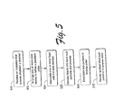
- Fig. 5 is a flow diagram that describes steps in a method in accordance with one embodiment.
- the method can be implemented in any suitable hardware, software, firmware or combination thereof.
- the method can be implemented in connection with the system shown and described in connection with Fig. 4 .
- Step 500 receives an indication that reverse playback is desired.
- This step can be implemented by receiving a communication or call from a software application that reverse playback is desired.
- This communication can include a range of source times over which reverse playback is desired.
- Step 502 arranges one or more data blocks to define a playback order. This step can be implemented by reading blocks that correspond to an indicated source time range in reverse. One example of how this can be done is given above.
- Step 504 associates one or more flags with the data block(s).
- the flag or flags are intended to indicate that one or more of the blocks of interest are subject to reverse playback.
- a reverse playback start flag and a reverse playback end flag can be associated with the block(s) of interest.
- Step 506 decodes blocks into individual block sub-portions and can further process the block sub-portions pursuant to the desired reverse playback. This can include, for example, buffering the block sub-portions for a predetermined period of time. For example, the block sub-portions can be buffered until all of the block sub-portions intended for reverse playback have been decoded. Alternately or additionally, the block sub-portions can be buffered until a pre-determined number or amount of sub-portions have been buffered.
- the buffered decoded data can also be used with compressed source data to completely regenerate the reverse playback stream. Additionally, the block sub-portions can also be processed so as to manipulate their associated timestamps. This can include reversing the effective order of the timestamps for the individual sub-portions. This can also include any timestamp processing due to any rate changes that might be requested. Such timestamp processing can include changing the values of the timestamps.
- Step 508 emits the block sub-portions in reverse order.
- the flag(s) of step 504 can be utilized to indicate that the block sub-portions should be emitted in reverse order.
- decoder 406 Fig. 4
- the presence of any flags can indicate that the decoder should emit the block sub-portions in reverse order.
- the decoder can then emit the block sub-portions in reverse order. One example of how this is done is given above.
- Step 510 then renders the emitted block sub-portions in the reverse order that the sub-portions were emitted.
- the same algorithm can be applied to break up a block into subblocks, which may be used by higher level components such as the source or decoder.
- the source is breaking up the entire video into subblocks (VOBUs in the DVD case) and emitting them in reverse order with reversed timestamps.
- the decoder can break the VOBUs into GOP blocks to pass to the renderer by reading and caching a VOBU, then emitting the cached data in reverse order.
- the methods and systems described above can take advantage of various pipelined video acceleration techniques in the graphics processor. This is particularly true for the decoder. This can permit the data pipeline to effectively run continuously and can avoid initialization startup costs.
- Various pipelined video acceleration techniques are described in U.S. Patent Application Serial No. 09/839,682 , entitled “An Extensible Multimedia Application Program Interface And Related Methods", filed on April 20, 2001, the disclosure of which is incorporated by reference herein.
- the decoder was configured to process any rate changes as well as any reverse playback requests from the application.
- Systems for pro cessing renderable data can, however, include more components in the chain or processing pipeline.
- Filter graph is a directed network of filters (or processing units). It can contain many different types of filters that are configured to process data to be finally rendered.
- filter graphs can contain transform filters, effects filters, network links, analysis filters and the like.
- rate changes can take place in one of two ways.
- the user can request that a rate change take place presently or "now, which semantically means at the next available time. Perhaps the user manipulates a slider in UI that affects the playback rate.
- a rate change can be scheduled at a given location in the source content. For example, perhaps the user indicates that a rate change to 2x is desirable starting at a source time of 00:00:05.
- the first scenario is the more difficult scenario because of the timing of the request and the state of the processing pipeline at that moment. It's possible that the source content has already been read by the source and forwarded to the next component in the pipeline.
- the second scenario is a less difficult problem, because one knows where the rate changes are going to occur and hence, the rate changes can be scheduled in advance.
- the source when it processes data, it reads the data from a particular medium and maps source times associated with the data to timestamps that are used to schedule rendering. For example, the table immediately below illustrates a representation of the mapping operation that is performed by the source for a forward play at 1x.
- Source Time Timestamp 00:00:01 Frame 1 (0 sec.) 00:00:02 Frame 2 (1 sec.) 00:00:03 Frame 3 (2 sec.) 00:00:04 Frame 4 (3 sec.) 00:00:05 Frame 5 (4 sec.)
- source times that correspond to 00:00:01 through 00:00:05 are mapped to timestamps that coincide with particular frames that are to be rendered. For example, 00:00:01 maps to a timestamp that corresponds to Frame 1; 00:00:02 maps to a timestamp that corresponds to Frame 2 and so on. Thus, there is a one-to-one mapping relationship for forward playback at 1x.
- the mapping operation When there is a request for a reverse playback, the mapping operation is charged somewhat. In this instance, the source still maps source times to timestamps. However, the source does so in a manner that not only provides a continuous, monotonically increasing stream of timestamps, but takes into account the reverse playback request as well.
- the table below illustrates a mapping operation for a reverse playback at 1x over the source time range of 00:00:01 through 00:00:05: Source Time Timestamp 00:00:01 Frame 5 (0 sec.) 00:00:02 Frame 4 (1 sec.) 00:00:03 Frame 3 (2 sec.) 00:00:04 Frame 2 (3 sec.) 00:00:05 Frame 1 (4 sec.)
- the source content is to be rendered for a source time range of 00:00:01 through 00:00:05, and then there is to be a jump to a source time range of 00:00:20 through 00:00:24.
- mapping operation would produce a stream of monotonically increasing timestamps as follows: Source Time Timestamp 00:00:01 Frame 1 (0 sec.) 00:00:02 Frame 2 (1 sec.) 00:00:03 Frame 3 (2 sec.) 00:00:04 Frame 4 (3 sec.) 00:00:05 Frame 5 (4 sec.) 00:00:20 Frame 6 (5 sec.) 00:00:21 Frame 7 (6 sec.) 00:00:22 Frame 8 (7 sec.) 00:00:23 Frame 9 (8 sec.) 00:00:24 Frame 10 (9 sec.)
- the source's responsibility is to receive requests from the application and map the context based location of the source data (i.e. the source times) into monotonically increasing output timestamps.
- a continuous stream of data can be provided to the renderer for rendering.
- the source can maintain a history of when it performed rate changes and where the rate changes map into a list of events that are to occur in the future. Then, if the application starts asking for rate changes at a particular time, the source is aware of how it has organized the rate changes in the past. It is also aware of whether the source content associated with any rate changes has already been passed to a downstream component for processing. If so, the source can take steps to attempt to have the rate change implemented by, for example, passing the rate change request to downstream components and having those components perform associated processing for implementing the rate change. In other approaches, any such rate change requests for source content that had already left the source were simply dropped.
- the source has the ability to query components within the processing pipeline to ascertain the capabilities of the components. For example, the source can query the components such as the decoder to ascertain whether they support reverse playback, which playback rates they support, their maximum and minimum playback rates and the like. By doing so, the source can then make intelligent decisions concerning how it reads the source data and, in some instances, the format of the source data that it sends along to the other components.
- the components such as the decoder to ascertain whether they support reverse playback, which playback rates they support, their maximum and minimum playback rates and the like.
- one or more of the pipeline components are provided with an interface (which is simply a collection of callable methods) that can be queried by the source.
- the source can query one or more of the interfaces to ascertain the capabilities of the components. For example, the source might query the components to ascertain if any of them support reverse playback. If not, this can cause the source to enter a simpler mode in which it does not support reverse playback and indicate that to the application which will make the application present a smarter UI to the user.
- the source can query to ascertain the playback rates that are supported. By knowing this, the source can adapt its processing to ensure that it does not overwhelm the pipeline. For example, if a particular playback speed is not supported by the pipeline, then the source may only send certain block portions (e.g. I frames only) for further processing by the pipeline. This helps to ensure that the pipeline is not unduly burdened with data that it cannot efficiently process, while at the same time attempts to provide a rendered display that is as close to the requested playback rate as possible.
- block portions e.g. I frames only
- Fig. 6 which shows an exemplary pipeline 600 that includes a source 602, demux 604, decoders 606, 606a, components 608, 608a, 610, 610a (which can be any suitable components), and renderers 612, 612a.
- source 602 queries demux 604; demux 604 queries decoders: 606, 606a, and so on.
- the query results can then be bubbled back up the pipeline.
- the source is interested in the maximum forward playback rates of the various components.
- each of the component's maximum rates is shown immediately beneath the component. So, for example, the maximum rate of renderer 612 is 2x; and the maximum rate of renderer 612a is 3x and so on.
- the source can make a decision on the maximum rate of the pipeline in general. First, the source can, in a conservative approach, simply take the minimum of all of the rates of the various components. So, in this particular example, the minimum of all of the rates is 2x. Hence, with this knowledge, the source can assume that any requested rates below 2x can be rendered smoothly without having to drop meaningful amounts of data.
- a second, more aggressive approach is to assume that there is a multiplicative effect as between the various components. For example, if a first component can support 2x and its downstream component can support 3x, then the maximum rate change that can be provided together by the components is 6x. Thus, in the figure, when the renderer 612 is queried by component 610, it reports a playback rate of 2x (which is indicated in parentheses between the components). Accordingly, component 610 can report, because of the multiplicative effect, a playback rate of 4x to component 608. Likewise, component 608 can report a playback rate of 8x to component 606 and so on. Assume in this example that demux 604 supports only a 1x playback rate.
- the demux 604 can now report to source 602 two playback rates-16x and 32x.
- the source can now select the lower of the two playback rate, i.e. 16x as the maximum playrate supported by the pipeline to achieve a generally smooth playback rate.
- the source knows the rate capabilities of the pipeline (e.g. 16x), it knows that it can provide entire data blocks to the pipeline when the requested rate equal to or less than 16x and the data will be rendered at this rate. It also knows that for any requested rate changes greater than 16x, it may have to do some additional processing to attempt to provide the higher rate. This can involve sending only truncated and/or selective blocks for processing by the pipeline. This mode is referred to as a "scan mode" where, for example, only keyframes might be sent by the source to the pipeline for processing.
- scan mode where, for example, only keyframes might be sent by the source to the pipeline for processing.
- Fig. 7 is a flow diagram that describes steps in a method in accordance with one embodiment.
- the method can be implemented in any suitable hardware, software, firmware or combination thereof.
- the method can be implemented in connection with a system such as the one shown and described in connection with Fig. 6 .
- Step 700 provides a data processing pipeline.
- Any suitable data processing pipeline can be provided.
- Suitable pipelines typically include one or more components that read source data off of some type of medium (such as a disk), demultiplex the data into individual data streams, decode the data and process it in some manner, and render the data for a user to enjoy. These different functionalities tend to be performed by different components-although such need not be the case.
- Step 702 queries a component for providing playback support capabilities.
- playback support capabilities include, without limitation, playback rates (maximum, minimum and/or a range of rates), playback directions (forward, reverse), and the like.
- Step 704 determines whether there are any components downstream of a queried component. If there are, step 706 goes to the next component and returns to step 702 to query the component to provide its playback support capabilities. If there are no additional downstream components, then step 708 reports the playback support capabilities up the data processing pipeline.
- the capabilities of each component can be reported to the source, which can then make intelligent data processing decisions. For example, the playback rates of each of the components can be reported to the source so that it can select the minimum playback rate.
- the capabilities of each of the components can be considered in connection with the capabilities of all of the other components. For example, the playback rates of all of the components in a particular pipeline or sub-pipeline can be multiplied so that an overall effective playback rate that is supported by the pipeline or sub-pipeline can be ascertained. Once ascertained, the source can make intelligent decisions on how to process data, as noted above.
- every suitably configured component can be thought of as a data manipulator. That is, individual components can partially process the data and pass along appropriate hints as to how the data has been manipulated. The next component can further process the data towards achieving a desired playback rate or direction.
- the source can reduce the amount of data that it provides to the decoder while at the same time maintain any timing information (such as a rate change) with the data. This gives the decoder a hint that a rate change is desired.
- the decoder can receive the data from the source and, in addition to decoding, can process it in a manner that attempts to achieve the rate change. Components in a chain can have the option of processing the data in a manner that is directed to achieving the desired playback, or, the component can pass the data down to the next component along with information on any rate changes. Such processing can include reversing data block portions, reassigning timestamps in an event that a reverse playback request has been received, and removing any associated flags from the data.
- the source is responsible for flipping the stream around at the block level and adding flags to indicate that reverse playback is intended.
- the blocks are then propagated downstream to other components.
- the component When a component encounters data having a reverse flag, the component has the option of passing the blocks to another component downstream, or processing the data to, for example, flip the order of the frames, remove the flags, and push the data to the next component.
- the renderers receive what looks like a forward stream having appropriately increasing timestamps.
- the application can request the source component to perform a rate change at a specific time or source time.
- the rate change information is then propagated through the pipeline until it encounters a component, whose queue contains a data sample with the source time associated with the rate change.
- the component can then queue up the rate change request so that the rate change is processed with the sample.
- the component can perform any necessary processing such as altering the output data (e.g. the sample's timestamp). If further processing is necessary, the component can pass along the rate change information (as well as any other useful information) with each output sample.
- the renderer will receive the sample and can schedule rendering. It is to be appreciated that the renderer can also be configured to implement playback or rate change processing as part of the distributed process.
- Another significant advantage is that the source's rate change queue is limited to data it has not sent or read yet. The remainder of the queue is distributed across the pipeline, which in most cases will be relatively short.
- the source can look in its buffers and ascertain whether the data relative to which the rate change is to take place is located in its buffers. The source can typically do this by noting the source times over which the rate change is to take place. If the data in the source's buffer have corresponding source times that are greater than the source times over which the rate change is to take place, then the data samples have already been passed to a downstream component. If the source locates a buffer that contains a data sample subject to the rate change, the source can associate rate change information with the sample.
- every data sample contains a list that includes properties that define (1) any rate changes, (2) the time range when the sample should be played, (3) whether the sample is to be played in forward or reverse.
- These lists are propagated along with the data sample so that components in the pipeline do not have to maintain a list of every rate change that has occurred in the past.
- the source checks its buffers and does not find the samples on which the rate change is to occur, the source sends the rate change request to the next downstream component.
- the next component then performs a similar process by checking its buffers to ascertain whether the buffers contain the sample on which the rate change is to occur. If the component finds the appropriate data sample, it can either add the rate change information to the sample when it processes the sample, or it can look into its buffers and attach the rate change information to the sample in its buffer. This process can be performed by any suitably configured components in the data pipeline.
- Fig. 8 is a flow diagram that describes steps in a method in accordance with one embodiment.
- the method can be implemented in any suitable hardware, software, firmware or combination thereof.
- the method can be implemented in connection with a system such as the one shown and described in connection with Fig. 6 .
- Step 800 receives a rate change request for a particular source time.
- the rate change request originates with an application and is passed to the source.
- step 802 examines one or more buffers to ascertain whether a corresponding data sample over which the rate change is to occur is present.
- the buffers that are examined are the buffers that are associated with the component that received the rate change request. If the sample is found (step 804) then step 806 attaches rate change information to the sample.
- This step can be implemented in a couple of ways.
- the rate change information can be attached to the sample while it is in the buffer. This can be implemented when the buffer is a read/write queue. Alternately, the rate change information can be cached and attached to the sample when it is processed by the component. This step can be implemented when the buffer is a read only queue.
- step 808 sends the rate change request to the next in line downstream component.
- step 810 then examines the buffers associated with the downstream component. This step can be implemented by the component that received the rate change request. If the sample is found (step 812), the method can branch to step 806. If, on the other hand, the sample is not found, step 814 determines whether there is another downstream component. If so, the method branches to step 808 and sends the rate change request to the next component. If, on the other hand, there are no additional downstream components, step 816 discards the rate change request. Presumably, this step is implemented by the renderer. Discarding the rate change request will only have a temporary effect on the output rate of the rendering.
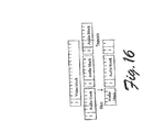
- Multiplexed data streams may not necessarily have secondary streams aligned at the video's keyframes. This poses problems when attempting to break up the content into distinct blocks separated by keyframes.
- FIG. 16 illustrates how extra data can be read for secondary streams and how it can be modified to match the video stream interval. For forward playback, rate changes in the same direction during full frame mode are not affected by clean points.
- the secondary streams either need to be trimmed or fragmented. Since a large amount of data is being skipped anyways, fragmentation may be preferable since it will simplify the source's design. More complex seeking can be added as an enhancement, but may incur a performance cost due to the seeking and interaction with the reader.
- trimmed secondary streams are required for continuous reverse audio.
- the buffering requirements tilt the buffer space
- the extra rapid decoding/discarding may not be feasible.
- the audio decoding is relatively fast compared to the video decoding.
- the source is responsible for discarding samples outside of the trimming range.
- An IRateChangeData interface is provided on each sample and is used to maintain rate change information, flags and rate change locations.
- a sample allocator creates samples that support the IRateChargeData interface.
- the interface IRateChangeControl (usually on the filter's input pin, or on the input to a component) provides a method ::ScheduleRateChange to request a rate change insertion. It also supports the method ::GetMaxRate to query the maximum forward and reverse decode rates.
- the method ::GetFurthestPosition is provided to query the furthest stream time that has not yet been processed and to determine the time interval for which rate changes can be scheduled after that time.
- ::ScheduleRateChangeNow requests that a rate change be scheduled at the next available time location and that the actual location be returned. This method could be called on the stream which is the least able to recover from missed rate changes.
- the :: ScheduleRateChange method would be called on the other streams using the location returned by ::ScheduleRateChangeNow.
- the example is drawn along the following assumptions concerning data format.
- scan is used to denote a truncated playback due to playback speed beyond a maximum rate supported by a pipeline or graph
- the source must be able to break the stream into disjoint blocks separated by clean points.
- a clean point is a location in the compressed data, where all streams are synchronized (i.e. each stream begins a new sample at the same presentation timestamp).
- the DVD source will use VOBUs as source blocks.
- the source will break the stream into GOPs since the video and the audio streams start new frames at keyframe boundaries.
- content without clean points such as general MPEG-2 content, please refer to the previous section on "Rate Changes for Data Without Clean Points".
- rate changes can be provided as real-time interactive changes, if they are in the same direction and in the same mode. Additionally, the decoder's bit rates are not exceeded when the maximum number of frames are displayed in scan mode. Additionally, timestamps are only modified by the renderers and the timestamp mapping code can be centralized and hidden.
- ScheduleRateChange() requests an rate change insertion
- ScheduleRateChangeNow() requests an rate change insertion at the soonest available time and returns the time at which it will occur
- ScheduleTruncation() requests an data truncation
- the method GetFurthestPosition() queries the furthest stream time that has not yet been processed
- the source is responsible for generating a continuous data stream
- the decoder is responsible for modifying the stream
- the renderer will ultimately be the rate change component. If the renderer does not support the rate change mechanisms, then the previous filter is responsible for acting on behalf of the renderer by altering timestamps to perform the rate change.
- the source is responsible for generating and managing timestamp information.
- the source should generate monotonically increasing streams by shifting out timestamp discontinuities and flipping around reverse playback blocks into forward stream blocks and tagging each to be played backwards.
- the source is also responsible for figuring out how to implement a user request for rate changes at particular locations. It also figures out how to schedule a rate change to be performed "now", by either
- the source Since samples are sent out with varying formats (e.g. forward versus reverse samples), the source maintains a block (e.g. a GOP or VOBU) history of the most recent direction change. A rate change in a different direction can only occur after the most recent direction change.
- a block e.g. a GOP or VOBU
- the decoder primarily acts as a stream preprocessor to aid the renderer (e.g. by cutting the b it rate, adding data for slow motion, and the like).
- the decoder performs as much interpolation as possible. It can also pass the rate change onto the next filter for subsequent processing.
- the decoder can also break reverse playback blocks into smaller reverse blocks for proc essing by the renderer.
- the original VOBU block can be decomposed into two or more smaller subblocks (GOPs in this example).
- the order of the subblocks are reversed and their timestamps are also reversed (see figure 14 ).
- the renderer then receives the new blocks and can reverse each one as it receives it. This has the advantage of reducing the amount of buffered uncompressed data that the renderer needs to retain.
- the decoder must modify its output timestamps to perform the rate change.
- the renderer ultimately implements rate change. It computes the effective presentation timestamp of a sample after the rate change. It also maintains a rate change history so that it can handle salvage/failure situations when, for example, a rate change cannot be done, or the renderer receives a rate change request that should have occurred in the past.
- the renderer can perform some buffering of output frames, then the renderer can actually perform the reverse playback using acceleration techniques.
- the renderer will receive reverse order samples from the decoder and begin recording or caching the decoded frames. Once the end of the reverse block has been received, the cached frames can be rendered in reverse order.
- the timestamp management code can be abstracted into a rate change management function that the renderer can use to map input timestamps (and rate change requests and possibly the current clock location) into an output timestamp for the sample.
- Fig. 14 illustrates a rate change request to be made by the user at a specified location.
- 12 frames of content have been sent to the renderers in various block sizes.
- the user has requested a rate change of 2x at time 00:00:15.
- the source maps the content specific location to the corresponding output sample 7's timestamp.
- the rate change requests are sent to each output pin to request that the next filter insert a rate change.
- the video decoder has buffered sample 7, so it attaches the rate change information to sample 7.
- the audio decoder has already processed sample 7, so it passes the request to the audio renderer.
- the renderer will break the next buffer into two sections to be played at different rates.
- Each renderer consults the timestamp manager to map each input timestamp into an output timestamp.
- a second situation occurs when the user wants to change the rate immediately.
- the source queries the next available timestamp and the amount of time available until it occurs. Using this timestamp, the source propagates a rate change down the pipeline or filter graph.
- the next available timestamp can be computed by the times tamp manager or in a distributed recursive fashion.
- the timestamp manager has the advantage of not requiring each filter along the chain to account for rate changes to the stream (by querying each queued sample for rate changes). As an example , consider Fig. 15 .
- the timestamp manager includes a registry. Each renderer registers and updates the timestamp manager with its current progress. The timestamp manager can compute the next available time to schedule a rate change and pass it back to the source (e.g. at frame 5, with 2 frames to propagate the rate change). The source can also find out where the renderers are (in source timestamps) and compute the source location to the application. The timestamp manager then extrapolates the location of each renderers and returns it to the source.
- timestamp mapping and registry functions occur at a central location, standardization and uniformity are enhanced in that these functions can be removed from other components in the pipeline. Additionally, errors can be reduced by providing a centralized location for the timestamp mapping.
- the methods and systems described above can provide improved methods and systems for processing renderable digital data.
- Various methods and systems permit digital data, such as video data, audio/video data, audio/video/subpicture data and the like, to be processed in a manner that permits playback in both forward and reverse directions in a manner that enhances the user's experience.
- Various embodiments can also handle playback rate changes in a manner that can enhance the user's experience.
- the invention may also refer to one or more of the following examples:
Abstract
Description
- This invention relates to methods and systems for processing renderable digital data, such as video data, audio/video data, and the like. In particular, the invention relates to methods and systems for processing playback speed or rate changes and directional changes (i.e. forward and reverse data playback).
- As the performance of processors, acceleration hardware and storage devices continue to improve, playback speeds beyond normal (i.e., 1.0) are possible. However, buffering and stream alignment issues limit the degree of interactivity between an application and user-perceived changes in the actual playback speed. It is possible to solve this problem in a monolithic and closed environment, where all the components of the solution are intertwined. But it's a much harder issue in the case of an open and componentized solution. Several attempts have been made to solve the problem, although each has fundamental flaws and oversights that have limited their usefulness.
- The playback rate (also referred to as the playback speed) determines the amount of time that each frame of data is displayed. Fast playback rates typically display frames for shorter periods of time than slower playback rates. Fast playback rates have high bandwidth requirements that can exceed most processor storage retrieval and hardware capabilities. Usually fast playback rates are approximated using so-called "scan modes" that selectively present only a (small) portion of a data stream by discarding some of the data of the stream. This is somewhat analogous to a rapidly progressing slide show.
- Many video applications, such as those that execute on computers or in connection with interactive television sets, are composed of a user interface that controls a source (or source filter). The source (or source filter) is part of a data processing pipeline that processes the data so that the data can be ultimately rendered for a user. The source reads media files and typically passes the data samples or buffers (which are usually compressed using, e.g., MPEG) to some type of decoder for processing. The decoder decompresses the data and passes it to some type of renderer that is configured to and capable of rendering the data for the user. The renderer typically uses an internal (or external) clock, and various timing information that is included with the data samples themselves, to present or render the samples at the correct time. When the renderer begins processing, an initial rendering clock time can be passed to the source and decoder. The source can then begin to produce samples with timestamps that start at some point after the initial renderer time. The timestamps are used by the renderer to schedule and render the various data samples based on their authored time of presentation. Small delays between pipeline and/or processing components (such as filters), can occur since samples are buffered between each stage in the data processing pipeline. The (graph or) pipeline latency is the cumulative propagation delay of the sample from the source (filter) to the time that it is presented or rendered. It has been and continues to be a goal of developers to enable systems to smoothly playback data, such as video content, at different playback rates (both in the forward and reverse directions). The nature of data processing pipelines and various data formats, however, continues to present challenges to developers.
- Consider, for example, some different data formats-the MPEG-2, DVD and HDTV formats.
- The MPEG-2 format is a format referred to as a "forward decoding" format. An example representation of an MPEG-2 format is shown in
Fig. 1 generally at 10. Each video sequence is composed of a series of Groups of Pictures (or "GOPs"). A GOP is composed of a sequence of pictures or frames. Frames can be encoded in three types: intra-frames (I-frames), forward predicted frames (P-frames), and bi-directional predicted frames (B-frames). - An I-frame or "key frame" (such as 1-frame 12) is encoded as a single image, with no reference to any past or future frames. The encoding scheme used is similar to JPEG compression. A P-frame (such as P-frame 18) is encoded relative to the past reference frame. P-frames can also be considered as "delta frames" in that they contain changes over their reference frame. A reference frame is a P- or I-frame. The past reference frame is the closest preceding reference frame. A B-frame (or bi-directional frame, such as frames 14 and 16) is encoded relative to the past reference frame, the future reference frame, or both frames. The future reference frame is the closest following reference frame (I or P). B-frames are a function of only the adjacent reference frames.
- The GOP structure is intended to assist random access into a sequence. A GOP is typically an independently decodable unit that can be of any size as long as it begins with an I-frame.
- One problem associated with the MPEG-2 format pertains to being able to playback the data in reverse. Playing the data forward is typically not a problem because the format itself is forward decoding-meaning that one must typically decode the I frame first and then move on to the other frames in the GOP. Playing back the data in reverse, however, is a little more challenging because one cannot backward-decode the GOP.
- Normally, when images are recorded on a disk, such as a DVD, the video is actually broken into small units covering a pre-determined time period (typically ½-second units or video object basic units ("VOBUs")). The advantage of this format is that when you play the video, you can progress through the video units one by one. If one wants to jump to an arbitrary piece of video, one can simply jump to the video unit of interest and the audio and video will be synchronized. The location at which all streams are synchronized is referred to as a "clean point". Accordingly, when the video and audio units are compressed, they are compressed in a unit that is to be rendered at the exact same time-that is, there is no skew between the audio and video.
- All references to I-frames when discussed within the MPEG2 context can be extended to keyframes in other data formats. The term I-frame is synonymous with a keyframe when discussed outside of the MPEG2 context.
- High Definition Television or HDTV uses the MPEG-2 format as well. Here, however, video blocks and audio blocks are aligned with a bit of a skew. In this case, one cannot simply fast forward or jump to a certain point in the stream because, while there may be a video sample at that point, the associated audio sample begins at another location in the stream. Additionally, the audio sample can only be decoded forward as a block. This means that one has to back up within the stream and look for the associated audio sample. Depending on the particular format, one may not really know where the beginning of the corresponding audio block or sample is located. Thus, one has to keep looking back in the stream for some point before both the video and audio samples of interest.
- With these different types of formats come challenges when one attempts to enable different playback rates and directions for an open and componentized solution.
- Consider now
Fig. 2 which illustrates an exemplary system 200 that can render data from a DVD. System 200 includes anapplication 202 that communicates with asource component 204 that reads data off of aDVD 206. The data that is read off of the DVD includes audio and video data that has been encoded and multiplexed together. As the source reads the data off of the DVD, it applies timestamps to the data packets which are then used to synchronize and schedule the packets for rendering. The packets are then provided to a demultiplexer (or "demux") 208 which splits the packets into different constituent portions-audio, video and, if present, subpicture packets. The packets are then provided by the demultiplexer to an associated decoder such as video decoder 210 (for decoding video packets), audio decoder 212 (for decoding audio packets) and subpicture decoder 214 (for decoding subpicture packets). Each one of the packets has associated timing information, which defines when the packet is supposed to be rendered. The various decoders then decompress their associated packets and send the individual data samples or packets (including the packets' timestamps) to the appropriate renderers—such asvideo renderer 216 andaudio renderer 218. - System 200 also typically includes a
global clock 220 that is used by the various renderers to ascertain when to render certain data samples whose timestamps coincide with a time indicated by the global clock. - Assume now that a user indicates, via
application 202, that he/she wish to have the data samples rendered at a different, perhaps faster rate. - A past approach for regulating a forward rate change is to manipulate the global clock 22 0. That is, if one wishes to play data twice as fast as the normal rate, then by manipulating the speed of the global clock, the desired rate change can be implemented. The problem with this approach is that the audio renderer can experience problems associated with frequency shifts and distorted audio output-which degrades the user's experience. Additionally, when the video renderer attempts to comply with the clock change, the video renderer can get behind in its processing which results in the renderer dropping samples to attempt to catch up. The overall result of this is a frequency shift on the audio, and a tug-and-pull on the video. The subpicture component, which can produce data that gets sent to the video renderer, can also have problems associated with the global clock change thus causing, for example, the subpicture to be rendered at an inappropriate time or in connection with inappropriate video. Thus, the quality of the output can be significantly degraded.
- Another approach that attempts to deal with a forward rate change is to have
source 204 notifydemultiplexer 208, which, in turn, notifiesvideo decoder 210 to make the appropriate rate change. Thedecoder 210 can then do scaling operations on the samples' timestamps to make the video play at a different rate. The problem with this approach is that there is no guarantee that thevideo decoder 210,audio decoder 212 andsubpicture decoder 214 will process the samples using the same techniques and algorithms-which is particularly true if the different decoders come from different vendors. Hence, the rate change can be affected at slightly different speeds which, in turn, can cause the video and audio to start to drift. Even worse, the subpicture can become unsynchronized which can cause it to appear at the wrong time. - Additionally, these two approaches were only really employed in the context of forward-played video and not backward-played video. Using these past approaches, there really was (and is) no way to tell the video renderer to play the video backwards. The video renderer typically has no control over or knowledge about how the video is read off of the disk.
- Accordingly, this invention arose out of concerns associated with providing improved methods and systems for processing renderable digital data.
- Various methods and systems permit digital data, such as video data, audio/video data, audio/video/subpicture data and the like, to be processed in a manner that permits playback in both forward and reverse directions. Various embodiments are also directed to handling playback rate changes in a manner that can enhance the user's experience.
-
-
Fig. 1 is diagram of an exemplary block of data that can b e processed in accordance with one or more embodiments. -
Fig. 2 is a block diagram of a system for processing data blocks. -
Fig. 3 is a block diagram of an exemplary computing environment within which principles of the described embodiment can be implemented. -
Fig. 4 is a block diagram of a system for processing data blocks in accordance with one embodiment. -
Fig. 5 is a flow diagram that describes steps in a method in accordance with one embodiment. -
Fig. 6 is a block diagram of a system for processing data blocks and illustrates certain aspects of one or more of the described embodiments. -
Fig. 7 is a flow diagram that describes steps in a method in accordance with one embodiment. -
Fig. 8 is a flow diagram that describes steps in a method in accordance with one embodiment. -
Figs. 9-13 are diagrams that illustrate exemplary data blocks in a manner that is useful for understanding one or more of the described embodiments. -
Fig. 14 is block diagram of an exemplary system for processing data blocks in accordance with one embodiment. -
Fig. 15 is block diagram of an exemplary system for processing data blocks in accordance with one embodiment. -
Fig. 16 is a diagram that illustrates a technique for processing complex data in accordance with one embodiment. - Various methods and systems described below permits digital data, such as video data, audio/video data, audio/video/subpicture data, to be processed in a manner that permits smooth playback in both forward and reverse directions. Additionally, playback rate changes can be handled in a manner that enhances the user's experience.
-
Fig. 3 illustrates an example of asuitable computing environment 300 on which the system and related methods described below can be implemented. - It is to be appreciated that computing
environment 300 is only one example of a suitable computing environment and is not intended to suggest any limitation as to the scope of use or functionality of the media processing system. Neither should thecomputing environment 300 be interpreted as having any dependency or requirement relating to any one or combination of components illustrated in theexemplary computing environment 300. - The various described embodiments can be operational with numerous other general purpose or special purpose computing system environments or configurations. Examples of well known computing systems, environments, and/or configurations that may be suitable for use with the media processing system include, but are not limited to, personal computers, server computers, thin clients, thick clients, hand-held or laptop devices, multiprocessor systems, microprocessor-based systems, set top boxes, programmable consumer electronics, network PCs, minicomputers, mainframe computers, distributed computing environments that include any of the above systems or devices, and the like.
- In certain implementations, the system and related methods may well be described in the general context of computer-executable instructions, such as program modules, being executed by a computer. Generally, program modules include routines, programs, objects, components, data structures, etc. that perform particular tasks or implement particular abstract data types. The embodiments can also be practiced in distributed computing environments where tasks are performed by remote processing devices that are linked through a communications network. In a distributed computing environment, program modules may be located in both local and remote computer storage media including memory storage devices.
- In accordance with the illustrated example embodiment of
Fig. 3 ,computing system 300 is shown comprising one or more processors orprocessing units 302, asystem memory 304, and abus 306 that couples various system components including thesystem memory 304 to theprocessor 302. -
Bus 306 is intended to represent one or more of any of several types of bus structures, including a memory bus or memory controller, a peripheral bus, an accelerated graphics port, and a processor or local bus using any of a variety of bus architectures. By way of example, and not limitation, such architectures include Industry Standard Architecture (ISA) bus, Micro Channel Architecture (MCA) bus, Enhanced ISA (EISA) bus, Video Electronics Standards Association (VESA) local bus, and Peripheral Component Interconnects (PCI) bus also known as Mezzanine bus. -
Computer 300 typically includes a variety of computer readable media. Such media may be any available media that is locally and/or remotely accessible bycomputer 300, and it includes both volatile and non-volatile media, removable and non-removable media. - In
Fig. 3 , thesystem memory 304 includes computer readable media in the form of volatile, such as random access memory (RAM) 310, and/or non-volatile memory, such as read only memory (ROM) 308. A basic input/output system (BIOS) 312, containing the basic routines that help to transfer information between elements withincomputer 300, such as during start-up, is stored inROM 308.RAM 310 typically contains data and/or program modules that are immediately accessible to and/or presently be operated on by processing unit(s) 302. -
Computer 300 may further include other removable/non-removable, volatile/non-volatile computer storage media. By way of example only,Fig. 3 illustrates ahard disk drive 328 for reading from and writing to a non-removable, non-volatile magnetic media (not shown and typically called a "hard drive"), amagnetic disk drive 330 for reading from and writing to a removable, non-volatile magnetic disk 332 (e.g., a "floppy disk"), and anoptical disk drive 334 for reading from or writing to a removable, non-volatileoptical disk 336 such as a CD-ROM, DVD-ROM or other optical media. Thehard disk drive 328,magnetic disk drive 330, andoptical disk drive 334 are each connected tobus 306 by one ormore interfaces 326. - The drives and their associated computer-readable media provide nonvolatile storage of computer readable instructions, data structures, program modules, and other data for
computer 300. Although the exemplary environment described herein employs ahard disk 328, a removablemagnetic disk 332 and a removableoptical disk 336, it should be appreciated by those skilled in the art that other types of computer readable media which can store data that is accessible by a computer, such as magnetic cassettes, flash memory cards, digital video disks, random access memories (RAMs), read only memories (ROM), and the like, may also be used in the exemplary operating environment. - A number of program modules may be stored on the
hard disk 328,magnetic disk 3 32,optical disk 336,ROM 308, orRAM 310, including, by way of example, and not limitation, anoperating system 314, one or more application programs 316 (e.g., multimedia application program 324),other program modules 318, andprogram data 320. A user may enter commands and information intocomputer 300 through input devices such askeyboard 338 and pointing device 340 (such as a "mouse"). Other input devices may include an audio/video input device(s) 353, a microphone, joystick, game pad, satellite dish, serial port, scanner, or the like (not shown). These and other input devices are connected to the processing unit(s) 302 through input interface(s) 342 that is coupled tobus 306, but may be connected by other interface and bus structures, such as a parallel port, game port, or a universal serial bus (USB). - A monitor 356 or other type of display device is also connected to
bus 306 via an interface, such as a video adapter or video/graphics card 344. In addition to the monitor, personal computers typically include other peripheral output devices (not shown), such as speakers and printers, which may be connected through outputperipheral interface 346. -
Computer 300 may operate in a networked environment using logical connections to one or more remote computers, such as aremote computer 350.Remote computer 350 may include many or all of the elements and features described herein relative to computer. - As shown in
Fig. 3 ,computing system 300 is communicatively coupled to remote devices (e.g., remote computer 350) through a local area network (LAN) 351 and a general wide area network (WAN) 352. Such networking environments are commonplace in offices, enterprise-wide computer networks, intranets, and the Internet. - When used in a LAN networking environment, the
computer 300 is connected toLAN 351 through a suitable network interface oradapter 348. When used in a WAN networking environment, thecomputer 300 typically includes amodem 354 or other means for establishing communications over theWAN 352. Themodem 354, which may be internal or external, may be connected to thesystem bus 306 via theuser input interface 342, or other appropriate mechanism. - In a networked environment, program modules depicted relative to the
personal computer 300, or portions thereof, may be stored in a remote memory storage device. By way of example, and not limitation,Fig. 3 illustratesremote application programs 316 as residing on a memory device ofremote computer 350. It will be appreciated that the network connections shown and described are exemplary and other means of establishing a communications link between the computers may be used. -
Fig. 4 diagrammatically illustrates a first embodiment in which digital data that is embodied on some type of media is processed so that it can be rendered in reverse. In this example, a system includes anapplication 400 th at provides an interface through which a user can interact with the particular digital media that is to be processed and rendered. The system also includes one ormore sources 402 for reading the data that is to be rendered, one ormore decoders 406 for decoding or decompressing data that is to be rendered, and one ormore renderers 408 for rendering the data (although only one of each type of component is shown). Digital media which is to be rendered byrenderer 408 is provided on amedia 410 which, in this example, comprises a disk such as a DVD. However, any type of medium can be utilized to store the digital media. It should be appreciated that while the source, decoder and renderer are shown as separate individual components, it is possible for the functionality of each to be provided in a more integrated fashion. -
Media 410 typically holds a large amount of data that can be rendered. The data is usually organized into logical units. Here, the logical units are represented as blocks. The term "blocks" is not intended to designate any specific type of data or medium. Rather, the term is used to illustrate the principles under which this embodiment operates. Accordingly, the illustrated blocks can represent different types or formats of data which usually break up the data into sections beginning with keyframes. For example, the blocks can comprise GOPs such as would be utilized to format data in the MPEG-1 or MPEG-2 format. The blocks can also represent VOBUs such as would be used to format data on a DVD. - One characteristic of such blocks is that the individual blocks are comprised of sub-portions that represent sub-components of the blocks. So, in the case where the block represents a GOP, individual sub-portions can include an I-frame and one or more P-frames or B-frames. The sub-portions of each block are indicated numerically inside each block. For example,
Block 1 is comprised ofsub-portions - Blocks can also be decomposed into smaller independent subblocks which are passed to downstream components to be processed as blocks. For example, in DVD a VOBU could contain several GOPs. The VOBU block can be broken into several subblocks, each containing a GOP. This is useful when playing content in reverse, since the larger blocks can be decomposed into smaller blocks whose order is reversed when they are sent downstream. New timestamps need to be computed for each of the new subblocks (see
figure 14 ). - When a user indicates, via
application 400, that they wish to play particular data (such as video data) in reverse,application 400 notifiessource 402 that reverse playback is intended. The application can also typically indicate a time range or source time over which the reverse playback is to occur. When thesource 402 enters a time period over which the reverse playback is to occur, the source reads blocks of data within the relative source time in reverse. - Consider, for example,
Fig. 4 . Notice thatmedia 410 is shown to include three individual blocks (designated asBlock 1,Block 2 and Block 3) as group A. Actually,media 410 includes many more blocks than those illustrated. Assume though, in this instance, that the user has indicated tosource 402 viaapplication 400 that they desire to play the blocks of group A in reverse. - As the source reads data from
media 410 it keeps track of the source time and when the source time coincides with Blocks 1-3, Blocks 1-3 are read in reverse order. Specifically,Block 3 is read first, thenBlock 2, and thenBlock 1. Hence, notice to the left ofsource 402 that the ordering of the blocks, as read, isBlock 3/Block 2/Block 1 to define agroup B. Source 402 then adds one or more flags to the blocks to indicate that they are intended for reverse playback. Specifically, notice that a start flag is added toBlock 3 and an end flag is added toBlock 1. Any suitable arrangement of flags can be used to designate the blocks for reverse playback. For example, the flags can be added to each block.Source 402 can also process the blocks by adding timestamps to the blocks. This can be done by mapping each block's source time to monotonically increasing timestamps that are used by the renderer to schedule rendering activities. - Each block is then provided by
source 402 todecoder 406. It will be appreciated that a demultiplexer or splitter can be interposed between the source and decoder-but for simplicity sake is not illustrated here. So, in this example,Block 3 can be provided todecoder 406, then Block 2 and finallyBlock 1. Alternately, the source can pre-parse blocks and send smaller subblocks of a block at a time in reverse order to the decoder for processing or decoding/decompressing. This reduces the size of the blocks propagating to the decoder. - When the
decoder 406 receives the blocks, it has to decode from left to right. But the flags on the block indicate to the decoder that it is to decode the blocks and reverse the order of the sub-portions (frames) of the blocks that it emits to renderer 408. Specifically, whendecoder 406 receivesBlock 3, it decodes the block as usual and can buffer the decoded block portions while it processes the other blocks. Thedecoder 406 similarly processesBlocks renderer 408 in reverse order: The emitted block sub-portions are designated as group C. - As can be seen, the renderer receives a stream of data that is reversed relative to the order that the stream would have if it was forward-played. The renderer can now schedule the stream for rendering. The renderer here is unaware of the stream being played in reverse direction, as that detail is confined within the source and decoder components.
- Now assume that the user wishes to implement a rate change to change the playback rate. In this embodiment, rate changes can be implemented as follows. Assume that a user wishes to have data rendered at a rate that is faster or slower than normal, i.e., 1x. Rate changes can be communicated to
source 402 viaapplication 400. The rate change information can be provided from the source to decoder 406 so that rate change processing can be performed by the decoder. In this embodiment, the decoder can perform rate change processing by manipulating the timestamps of the samples or block sub-portions that it processes. For example, if a group of samples is to be rendered at 1x and has timestamps that extend from t1 to t4 , such samples can be rendered at 2x by changing the timestamps from t1 - t4 to t1 - t2, where t2 - t1 = (t4 - t1 ) / 2. -
Fig. 5 is a flow diagram that describes steps in a method in accordance with one embodiment. The method can be implemented in any suitable hardware, software, firmware or combination thereof. In the illustrated example, the method can be implemented in connection with the system shown and described in connection withFig. 4 . - Step 500 receives an indication that reverse playback is desired. This step can be implemented by receiving a communication or call from a software application that reverse playback is desired. This communication can include a range of source times over which reverse playback is desired. Step 502 arranges one or more data blocks to define a playback order. This step can be implemented by reading blocks that correspond to an indicated source time range in reverse. One example of how this can be done is given above. Step 504 associates one or more flags with the data block(s). The flag or flags are intended to indicate that one or more of the blocks of interest are subject to reverse playback. Here, a reverse playback start flag and a reverse playback end flag can be associated with the block(s) of interest.
- Step 506 decodes blocks into individual block sub-portions and can further process the block sub-portions pursuant to the desired reverse playback. This can include, for example, buffering the block sub-portions for a predetermined period of time. For example, the block sub-portions can be buffered until all of the block sub-portions intended for reverse playback have been decoded. Alternately or additionally, the block sub-portions can be buffered until a pre-determined number or amount of sub-portions have been buffered. The buffered decoded data can also be used with compressed source data to completely regenerate the reverse playback stream. Additionally, the block sub-portions can also be processed so as to manipulate their associated timestamps. This can include reversing the effective order of the timestamps for the individual sub-portions. This can also include any timestamp processing due to any rate changes that might be requested. Such timestamp processing can include changing the values of the timestamps.
- Step 508 emits the block sub-portions in reverse order. In this step, the flag(s) of
step 504 can be utilized to indicate that the block sub-portions should be emitted in reverse order. Thus, when for example, decoder 406 (Fig. 4 ) processes the block sub-portions, the presence of any flags can indicate that the decoder should emit the block sub-portions in reverse order. The decoder can then emit the block sub-portions in reverse order. One example of how this is done is given above. Step 510 then renders the emitted block sub-portions in the reverse order that the sub-portions were emitted. - The same algorithm can be applied to break up a block into subblocks, which may be used by higher level components such as the source or decoder. Effectively, the source is breaking up the entire video into subblocks (VOBUs in the DVD case) and emitting them in reverse order with reversed timestamps. The decoder can break the VOBUs into GOP blocks to pass to the renderer by reading and caching a VOBU, then emitting the cached data in reverse order.
- The above-described processes and systems have a higher requirement of memory to buffer the decoded block sub-portions. But the advantages of this approach include the following. First, some systems attempt to achieve reverse playback by repeating a process that effectively jumps backward in position and plays forward for a number of frames, and then again jumps backward in position and plays forward for a number of frames. This process can become extremely computationally inefficient since it repeats work and will usually degrade the user's experience. Other approaches can only work on one data block at a time.
- The above systems and methods can actually change the order of multiple blocks when reverse playback is desired. Further, use of flags permits the system to actually render individual block sub-portions or frames in reverse order. Also rate changes can be smoothly provided by manipulating the timestamps of the block sub-portions. Other advantages will be apparent to those of skill in the art.
- As a performance advantage, the methods and systems described above can take advantage of various pipelined video acceleration techniques in the graphics processor. This is particularly true for the decoder. This can permit the data pipeline to effectively run continuously and can avoid initialization startup costs. Various pipelined video acceleration techniques are described in
U.S. Patent Application Serial No. 09/839,682 - In the embodiment described above, the decoder was configured to process any rate changes as well as any reverse playback requests from the application. Systems for pro cessing renderable data can, however, include more components in the chain or processing pipeline. For example, one type of processing pipeline is known as a filter graph. Filter graph is a directed network of filters (or processing units). It can contain many different types of filters that are configured to process data to be finally rendered. In addition to source and decoder filters, such filter graphs can contain transform filters, effects filters, network links, analysis filters and the like.
- It can be advantageous to distribute playback and rate change processing across the system, pipeline or filter graph. One reason for this is increased flexibility of implementation as well as an open and extensible architecture. For example, if the user requests a rate change for a sample that has already been processed by the decoder, but which is queued up at a downstream component that is unable to effectuate the rate change, most if not all current systems will typically ignore the rate change.
- Typically, rate changes can take place in one of two ways. First, the user can request that a rate change take place presently or "now, which semantically means at the next available time. Perhaps the user manipulates a slider in UI that affects the playback rate. Second, a rate change can be scheduled at a given location in the source content. For example, perhaps the user indicates that a rate change to 2x is desirable starting at a source time of 00:00:05. These two scenarios are fundamentally different. The first scenario is the more difficult scenario because of the timing of the request and the state of the processing pipeline at that moment. It's possible that the source content has already been read by the source and forwarded to the next component in the pipeline. The second scenario is a less difficult problem, because one knows where the rate changes are going to occur and hence, the rate changes can be scheduled in advance.
- As noted above, when the source processes data, it reads the data from a particular medium and maps source times associated with the data to timestamps that are used to schedule rendering. For example, the table immediately below illustrates a representation of the mapping operation that is performed by the source for a forward play at 1x.
Source Time Timestamp 00:00:01 Frame 1 (0 sec.) 00:00:02 Frame 2 (1 sec.) 00:00:03 Frame 3 (2 sec.) 00:00:04 Frame 4 (3 sec.) 00:00:05 Frame 5 (4 sec.) - In the table above, source times that correspond to 00:00:01 through 00:00:05 are mapped to timestamps that coincide with particular frames that are to be rendered. For example, 00:00:01 maps to a timestamp that corresponds to Frame 1; 00:00:02 maps to a timestamp that corresponds to Frame 2 and so on. Thus, there is a one-to-one mapping relationship for forward playback at 1x.
- When there is a request for a reverse playback, the mapping operation is charged somewhat. In this instance, the source still maps source times to timestamps. However, the source does so in a manner that not only provides a continuous, monotonically increasing stream of timestamps, but takes into account the reverse playback request as well. For example, the table below illustrates a mapping operation for a reverse playback at 1x over the source time range of 00:00:01 through 00:00:05:
Source Time Timestamp 00:00:01 Frame 5 (0 sec.) 00:00:02 Frame 4 (1 sec.) 00:00:03 Frame 3 (2 sec.) 00:00:04 Frame 2 (3 sec.) 00:00:05 Frame 1 (4 sec.) - Notice here that the source times are reassigned to reflect reverse playback, but the corresponding timestamps continue to monotonically increase. Thus, when the renderer receives the data samples, it will schedule rendering so as to affect reverse playback.
- Now assume that there is a jump to another portion of the source content. Perhaps the source content is to be rendered for a source time range of 00:00:01 through 00:00:05, and then there is to be a jump to a source time range of 00:00:20 through 00:00:24. In this case, the mapping operation would produce a stream of monotonically increasing timestamps as follows:
Source Time Timestamp 00:00:01 Frame 1 (0 sec.) 00:00:02 Frame 2 (1 sec.) 00:00:03 Frame 3 (2 sec.) 00:00:04 Frame 4 (3 sec.) 00:00:05 Frame 5 (4 sec.) 00:00:20 Frame 6 (5 sec.) 00:00:21 Frame 7 (6 sec.) 00:00:22 Frame 8 (7 sec.) 00:00:23 Frame 9 (8 sec.) 00:00:24 Frame 10 (9 sec.) - Thus, in this embodiment, the source's responsibility is to receive requests from the application and map the context based location of the source data (i.e. the source times) into monotonically increasing output timestamps. In doing so, a continuous stream of data can be provided to the renderer for rendering. This is advantageous from the standpoint of other components, particularly the decoder, in that the other component do not need to keep track of timestamps and where they are in a particular process. Rather, the other components can simply receive and process samples having a linear stream of timestamps.
- To facilitate processing at the source, the source can maintain a history of when it performed rate changes and where the rate changes map into a list of events that are to occur in the future. Then, if the application starts asking for rate changes at a particular time, the source is aware of how it has organized the rate changes in the past. It is also aware of whether the source content associated with any rate changes has already been passed to a downstream component for processing. If so, the source can take steps to attempt to have the rate change implemented by, for example, passing the rate change request to downstream components and having those components perform associated processing for implementing the rate change. In other approaches, any such rate change requests for source content that had already left the source were simply dropped.
- One advantageous feature of some of the embodiments described above and below is that the source has the ability to query components within the processing pipeline to ascertain the capabilities of the components. For example, the source can query the components such as the decoder to ascertain whether they support reverse playback, which playback rates they support, their maximum and minimum playback rates and the like. By doing so, the source can then make intelligent decisions concerning how it reads the source data and, in some instances, the format of the source data that it sends along to the other components.
- As an example, consider the following. To implement rate changes and to do so intelligently, it can be advantageous for the source to know the maximum rate that is supported by the entire pipeline or filter graph. This can be the case for both forward and reverse playback. In this embodiment, one or more of the pipeline components are provided with an interface (which is simply a collection of callable methods) that can be queried by the source. When the pipeline is constructed or instantiated, the source can query one or more of the interfaces to ascertain the capabilities of the components. For example, the source might query the components to ascertain if any of them support reverse playback. If not, this can cause the source to enter a simpler mode in which it does not support reverse playback and indicate that to the application which will make the application present a smarter UI to the user. This can include, for example, to just reading the key frames of the blocks in the reverse order, rather than reverse reading the whole block and tagging them with appropriate flags, which the decoder cannot act upon anyway. Additionally, the source can query to ascertain the playback rates that are supported. By knowing this, the source can adapt its processing to ensure that it does not overwhelm the pipeline. For example, if a particular playback speed is not supported by the pipeline, then the source may only send certain block portions (e.g. I frames only) for further processing by the pipeline. This helps to ensure that the pipeline is not unduly burdened with data that it cannot efficiently process, while at the same time attempts to provide a rendered display that is as close to the requested playback rate as possible.
- One way of implementing the querying process is as follows. When the source first starts out or is instantiated, it queries, either directly or indirectly, every component down the pipeline for their capabilities, e.g. their maximum forward and reverse rates. One way of doing this is for the source to query the first downstream component, and for the first downstream component to query its first downstream component and so on. As an example, consider
Fig. 6 which shows anexemplary pipeline 600 that includes asource 602,demux 604,decoders components renderers source 602 queries demux 604; demux 604 queries decoders: 606, 606a, and so on. The query results can then be bubbled back up the pipeline. - Assume in this example that the source is interested in the maximum forward playback rates of the various components. In this example, each of the component's maximum rates is shown immediately beneath the component. So, for example, the maximum rate of
renderer 612 is 2x; and the maximum rate ofrenderer 612a is 3x and so on. There are a couple of ways that the source can make a decision on the maximum rate of the pipeline in general. First, the source can, in a conservative approach, simply take the minimum of all of the rates of the various components. So, in this particular example, the minimum of all of the rates is 2x. Hence, with this knowledge, the source can assume that any requested rates below 2x can be rendered smoothly without having to drop meaningful amounts of data. A second, more aggressive approach, is to assume that there is a multiplicative effect as between the various components. For example, if a first component can support 2x and its downstream component can support 3x, then the maximum rate change that can be provided together by the components is 6x. Thus, in the figure, when therenderer 612 is queried bycomponent 610, it reports a playback rate of 2x (which is indicated in parentheses between the components). Accordingly,component 610 can report, because of the multiplicative effect, a playback rate of 4x tocomponent 608. Likewise,component 608 can report a playback rate of 8x tocomponent 606 and so on. Assume in this example that demux 604 supports only a 1x playback rate. Thedemux 604 can now report tosource 602 two playback rates-16x and 32x. In accordance with this approach, the source can now select the lower of the two playback rate, i.e. 16x as the maximum playrate supported by the pipeline to achieve a generally smooth playback rate. - Once the source knows the rate capabilities of the pipeline (e.g. 16x), it knows that it can provide entire data blocks to the pipeline when the requested rate equal to or less than 16x and the data will be rendered at this rate. It also knows that for any requested rate changes greater than 16x, it may have to do some additional processing to attempt to provide the higher rate. This can involve sending only truncated and/or selective blocks for processing by the pipeline. This mode is referred to as a "scan mode" where, for example, only keyframes might be sent by the source to the pipeline for processing.
-
Fig. 7 is a flow diagram that describes steps in a method in accordance with one embodiment. The method can be implemented in any suitable hardware, software, firmware or combination thereof. In the illustrated example, the method can be implemented in connection with a system such as the one shown and described in connection withFig. 6 . - Step 700 provides a data processing pipeline. Any suitable data processing pipeline can be provided. Suitable pipelines typically include one or more components that read source data off of some type of medium (such as a disk), demultiplex the data into individual data streams, decode the data and process it in some manner, and render the data for a user to enjoy. These different functionalities tend to be performed by different components-although such need not be the case.
- Step 702 queries a component for providing playback support capabilities. Examples of playback support capabilities include, without limitation, playback rates (maximum, minimum and/or a range of rates), playback directions (forward, reverse), and the like. Step 704 determines whether there are any components downstream of a queried component. If there are,
step 706 goes to the next component and returns to step 702 to query the component to provide its playback support capabilities. If there are no additional downstream components, then step 708 reports the playback support capabilities up the data processing pipeline. - This step can be implemented in a couple of different ways. First, as noted above, the capabilities of each component can be reported to the source, which can then make intelligent data processing decisions. For example, the playback rates of each of the components can be reported to the source so that it can select the minimum playback rate. Second, the capabilities of each of the components can be considered in connection with the capabilities of all of the other components. For example, the playback rates of all of the components in a particular pipeline or sub-pipeline can be multiplied so that an overall effective playback rate that is supported by the pipeline or sub-pipeline can be ascertained. Once ascertained, the source can make intelligent decisions on how to process data, as noted above.
- In the example embodiments described above, every suitably configured component (filter) can be thought of as a data manipulator. That is, individual components can partially process the data and pass along appropriate hints as to how the data has been manipulated. The next component can further process the data towards achieving a desired playback rate or direction.
- If necessary, for example, the source can reduce the amount of data that it provides to the decoder while at the same time maintain any timing information (such as a rate change) with the data. This gives the decoder a hint that a rate change is desired. The decoder can receive the data from the source and, in addition to decoding, can process it in a manner that attempts to achieve the rate change. Components in a chain can have the option of processing the data in a manner that is directed to achieving the desired playback, or, the component can pass the data down to the next component along with information on any rate changes. Such processing can include reversing data block portions, reassigning timestamps in an event that a reverse playback request has been received, and removing any associated flags from the data.
- Thus, in this example, the source is responsible for flipping the stream around at the block level and adding flags to indicate that reverse playback is intended. The blocks are then propagated downstream to other components. When a component encounters data having a reverse flag, the component has the option of passing the blocks to another component downstream, or processing the data to, for example, flip the order of the frames, remove the flags, and push the data to the next component. Ultimately then, the renderers receive what looks like a forward stream having appropriately increasing timestamps.
- The above-described embodiments work well when a rate change is to occur at a given time, and the source has not yet read the data blocks over which the rate change is to be implemented. There is another situation, briefly mentioned above, where a rate change request is received after the source has read the data blocks and/or passed the blocks along to a downstream component for processing.
- In the embodiment about to be described, flexibility is enhanced by distributing processing across the component pipeline or filter graph. Specifically, the application can request the source component to perform a rate change at a specific time or source time. The rate change information is then propagated through the pipeline until it encounters a component, whose queue contains a data sample with the source time associated with the rate change. The component can then queue up the rate change request so that the rate change is processed with the sample. When the corresponding sample is processed by the component, the component can perform any necessary processing such as altering the output data (e.g. the sample's timestamp). If further processing is necessary, the component can pass along the rate change information (as well as any other useful information) with each output sample. Eventually the renderer will receive the sample and can schedule rendering. It is to be appreciated that the renderer can also be configured to implement playback or rate change processing as part of the distributed process.
- Another significant advantage is that the source's rate change queue is limited to data it has not sent or read yet. The remainder of the queue is distributed across the pipeline, which in most cases will be relatively short.
- As an example, consider the following. When an application sends a rate change request to then source, the source can look in its buffers and ascertain whether the data relative to which the rate change is to take place is located in its buffers. The source can typically do this by noting the source times over which the rate change is to take place. If the data in the source's buffer have corresponding source times that are greater than the source times over which the rate change is to take place, then the data samples have already been passed to a downstream component. If the source locates a buffer that contains a data sample subject to the rate change, the source can associate rate change information with the sample.
- That is, in accordance with this embodiment, every data sample contains a list that includes properties that define (1) any rate changes, (2) the time range when the sample should be played, (3) whether the sample is to be played in forward or reverse. These lists are propagated along with the data sample so that components in the pipeline do not have to maintain a list of every rate change that has occurred in the past.
- If the source checks its buffers and does not find the samples on which the rate change is to occur, the source sends the rate change request to the next downstream component. The next component then performs a similar process by checking its buffers to ascertain whether the buffers contain the sample on which the rate change is to occur. If the component finds the appropriate data sample, it can either add the rate change information to the sample when it processes the sample, or it can look into its buffers and attach the rate change information to the sample in its buffer. This process can be performed by any suitably configured components in the data pipeline.
-
Fig. 8 is a flow diagram that describes steps in a method in accordance with one embodiment. The method can be implemented in any suitable hardware, software, firmware or combination thereof. In the illustrated example, the method can be implemented in connection with a system such as the one shown and described in connection withFig. 6 . - Step 800 receives a rate change request for a particular source time. Typically, the rate change request originates with an application and is passed to the source. Responsive to receiving the rate change request,
step 802 examines one or more buffers to ascertain whether a corresponding data sample over which the rate change is to occur is present. The buffers that are examined are the buffers that are associated with the component that received the rate change request. If the sample is found (step 804) then step 806 attaches rate change information to the sample. This step can be implemented in a couple of ways. For example, the rate change information can be attached to the sample while it is in the buffer. This can be implemented when the buffer is a read/write queue. Alternately, the rate change information can be cached and attached to the sample when it is processed by the component. This step can be implemented when the buffer is a read only queue. - If, on the other hand, the sample is not found in the component's buffers,
step 808 sends the rate change request to the next in line downstream component. Step 810 then examines the buffers associated with the downstream component. This step can be implemented by the component that received the rate change request. If the sample is found (step 812), the method can branch to step 806. If, on the other hand, the sample is not found,step 814 determines whether there is another downstream component. If so, the method branches to step 808 and sends the rate change request to the next component. If, on the other hand, there are no additional downstream components, step 816 discards the rate change request. Presumably, this step is implemented by the renderer. Discarding the rate change request will only have a temporary effect on the output rate of the rendering. - Multiplexed data streams (such as ATSC MPEG2) may not necessarily have secondary streams aligned at the video's keyframes. This poses problems when attempting to break up the content into distinct blocks separated by keyframes.
- There are two solutions to generate data for the secondary streams for an arbitrary time interval corresponding to the block of primary stream data:
- 1) Trimming
The source seeks backwards in the content such that every stream has data present in the interval and each stream is told to skip to the start timestamp of the interval. - 2) Discard fragments
The source seeks to the start of the primary stream and the secondary stream discard the block fragments until the next frame start. The stream will be missing data for this interval and a discontinuity will have to be sent at the start of the interval. - A truncation marker will need to be inserted in each stream to end the data after the time interval.
Fig. 16 illustrates how extra data can be read for secondary streams and how it can be modified to match the video stream interval. For forward playback, rate changes in the same direction during full frame mode are not affected by clean points. - For forwards or reverse keyframe scan mode, the secondary streams either need to be trimmed or fragmented. Since a large amount of data is being skipped anyways, fragmentation may be preferable since it will simplify the source's design. More complex seeking can be added as an enhancement, but may incur a performance cost due to the seeking and interaction with the reader.
- For smooth reverse playback, trimmed secondary streams are required for continuous reverse audio. However, the buffering requirements (twice the buffer space) on the source and the extra rapid decoding/discarding may not be feasible. However the audio decoding is relatively fast compared to the video decoding.
- The source is responsible for discarding samples outside of the trimming range.
- Aspects of the above-described embodiments will now be described in the context of a specific implementation example. It is to be understood that the example described below is intended for illustrative purposes and should not be construed to limit application of the claimed subject matter.
- The example about to be described utilizes the following architectural aspects. An IRateChangeData interface is provided on each sample and is used to maintain rate change information, flags and rate change locations. A sample allocator creates samples that support the IRateChargeData interface. The interface IRateChangeControl (usually on the filter's input pin, or on the input to a component) provides a method ::ScheduleRateChange to request a rate change insertion. It also supports the method ::GetMaxRate to query the maximum forward and reverse decode rates. The method ::GetFurthestPosition is provided to query the furthest stream time that has not yet been processed and to determine the time interval for which rate changes can be scheduled after that time.
- Another method, ::ScheduleRateChangeNow requests that a rate change be scheduled at the next available time location and that the actual location be returned. This method could be called on the stream which is the least able to recover from missed rate changes. The :: ScheduleRateChange method would be called on the other streams using the location returned by ::ScheduleRateChangeNow.
- In addition, the example is drawn along the following assumptions concerning data format. For smooth reverse, reverse scan and forward scan playback (where the term "scan" is used to denote a truncated playback due to playback speed beyond a maximum rate supported by a pipeline or graph), usually the source must be able to break the stream into disjoint blocks separated by clean points. A clean point is a location in the compressed data, where all streams are synchronized (i.e. each stream begins a new sample at the same presentation timestamp). For example, the DVD source will use VOBUs as source blocks. For other content formats, the source will break the stream into GOPs since the video and the audio streams start new frames at keyframe boundaries. For content without clean points, such as general MPEG-2 content, please refer to the previous section on "Rate Changes for Data Without Clean Points".
- With respect to scheduling and processing a rate change request:
- The filter sends an IRateChangeControl::ScheduleRateChange request to the decoder to insert a mid-sample rate change at a specific source timestamp. The decoder determines if it will encounter a sample containing the rate change location. If it has already processed the timestamp or does not handle rate changes, it passes the rate change request to each of its output pins controlled by corresponding to the input pin.
- Alternatively, to schedule an immediate rate change the filter sends an IRateChangeControl::ScheduleRateChangeNow request to the decoder (usually of the stream which cannot easily recover from data loss, e.g. audio which would cause noticeable 'pops') to insert a mid-sample rate change at a the next available source timestamp. The request is recursively passed downstream until a component decides that it must process the rate change insertion request. The actual location is returned up the stream to the initial filter. The filter then propagates the rate change request to the other streams using the timestamp returned by the ScheduleRateChangeNow request.
- When the decoder handles the request, it internally queues the rate change information to be processed when it receives a sample containing the rate change timestamp. When the sample is encountered, the decoder performs any rate change interpolation and copies the rate change information into the output sample's IRateChangeData interface.
- Timestamp information in the data stream is not altered directly by the source or any intermediate filters. Each filter simply modifies the stream's contents.
- With respect to computing rate changes:
- The source filter uses the IRateChangeControl::GetMaxRate method to query the decoder's maximum forward and backward playback bit rates. If the global flag is set to true, then a filter must compute and return the maximum rates of both its corresponding output pins and its maximum internal rate.
- With respect to the IRateChangeData interface:
- The IRateChangeData interface is used to both indicate the presence of a rate change and to store rate change information related to the sample.
- The IRateChangeData interface maintains the following information:
- o LONG Rate - a signed fixed point scale value (x100000) where a negative value indicates reverse playback. A value of 0 indicates that no rate change event is present in this sample (although the flags field may still contain sample information).
- ○ REFERENCETIME Location - The source timestamp location of the rate change
- ○ DWORD Flags - A bit wise OR of the following flags
- ■ Flag_ReverseStart - the first sample in a 'reverse playback' group of samples
- ■ Flag_ReverseEnd - the last sample in a 'reverse playback' group of samples
- ■ Flag_ScanMode - part of a video section in forward or reverse scan mode
- ■ Flag_TruncationPoint - the Location specifies that the sample should be truncated at this point. The 'Rate' field is not used.
- ■ Flag_SkipPoint - the Location specifies that the start of the sample up to this point should be discarded. The 'Rate' field is not used.
- With respect to timestamps and data interpretation at different playback rates:
- The source filter is responsible for ensuring that timestamps are continuous and monotonically increasing. Timestamps are modified to appear as a continuous linear piece of video. Discontinuities indicate that there is a break in the source data.
- Changes in playback direction can only occur at sample boundaries and not in the middle of a 'reverse playback' group of samples (see below).
- In smooth forward playback (below the maximum forward rate), samples are sent normally as indicated in
Fig. 9 . - For smooth reverse play, it is assumed that decoders decode blocks of samples forward, and then deliver the frames in reverse order. The Flag_ReverseStart flag (in the IRateChangeData::Flags data field) indicates that this sample is the first sample in a group of samples that is intended to be played backwards. The Flag_ReverseEnd flag indicates that the sample is the last sample of a "reverse playback" group of samples. The start and end timestamps of the interval over which the samples are to be played does not change. The display order of the data is reversed as indicated in
Fig. 10 . - The display timestamp of a frame in the first interval is computed as:

- During forward (or reverse) scan playback beyond the maximum rate, only keyframes (I frames) are sent to the decoder (without discontinuities) as approximations of the video to be displayed for the time interval. The output timestamp will be the same as the original interval's end timestamp as noted in
Fig. 11 . Timestamps are modified to appear as a linear piece of video played at 1x speed. The start and end timestamps indicate the period over which the sample is to be played. - Transitions between scan (only keyframes sent) and smooth modes (full video sent) inherently change the actual data. A rate change at a rate below the maximum rate indicates samples will be sent in smooth mode; otherwise samples are sent in scan mode. Each sample's IRateChangeData flags contains a hint to aid the decoder in determining the mode of the sample (smooth or scan, and reverse or forward).
- A direction change is indicated by a change in the sign of the rate.
Direction changes can only occur at sample boundaries and cannot occur in the middle of 'reverse playback' groups of samples. - Multiple same-direction rate changes can occur within a sample and across samples of mixed scan and non-scan modes as illustrated in
Fig. 12 . - The rate change mechanism in this example only assumes that the video format can be broken into blocks separated by keyframes. To ensure that timestamps monotonically increase, the length of each block (between keyframes) must be computable by the source filter to compute the end timestamp and the next timestamp of the subsequence key frame.
- Timestamps are not usually modified by filters as they propagate through the pipeline. The renderers modify the timestamps (using a rate change command stream) to produce the output timestamps. If a component does not modify timestamps, then it must map all output timestamp information back into the input timestamp (and vice versa) when queried for its location or when propagating rate change information downstream.
- It is possible for a source filter not to attach timestamps to the samples, but to indicate that they are part of a reverse playback block. In this situation, the first filter to read in-band timestamps is responsible for generating monotonically increasing timestamps on the samples belonging to the whole block.
- An intermediate filter is permitted to break up a reverse sample into smaller reverse samples, sent in the reverse order that they are received, as indicated in
Fig. 13 . - The above described example embodies several advantages. First, rate changes can be provided as real-time interactive changes, if they are in the same direction and in the same mode. Additionally, the decoder's bit rates are not exceeded when the maximum number of frames are displayed in scan mode. Additionally, timestamps are only modified by the renderers and the timestamp mapping code can be centralized and hidden.
- In this particular implementation example, the following interfaces can be used:
     Interface IRateChangeControl
     {
            HRESULT ScheduleRateChange( TIME SourcePosition,
                   LONG Rate)
            HRESULT ScheduleRateChangeNow( LONG Rate,
                   TIME* pActualSourcePosition)
            HRESULT ScheduleTruncation(TIME SourcePosition)
            HRESULT ScheduleSkip(TIME SourcePosition)
            HRESULT GetMaxRate( BOOL IncludeDownstream,
                   DWORD* pForwardRate, DWORD* pReverseRate)
            HRESULT GetFurthestPosition( BOOL IncludeDownstream,
                   TIME* pSourcePosition, TIME* pValidDuration)
     }
- The SourcePosition parameter specifies the timestamp to execute the rate change at relative to the source timestamps
- The Rate specifies the rate x 10000, which is negative if in reverse
playback
- The pActualSourcePosition parameter returns the actual timestamp the rate change was scheduled for
- The Rate specifies the rate x 10000, which is negative if in reverse
playback
- The SourcePosition parameter specifies the timestamp to truncate the sample at
- The method ScheduleSkip() requests an data skip from the start of the sample
- The SourcePosition parameter specifies the timestamp to skip from
the start of the sample to
- The pForwardRate and pBackwardRate parameters return positive values indicating the maximum relative forward and backward playback rates
- The IncludeDownstream flag indicates that the component should recursively include any downstream dependencies in its computation
- The pSourcePosition is a return parameter which indicates the current timestamp (relative to the source timestamps) of the output.
- The pValidPeriod is a return parameter which indicates the duration after the source position which the rate change could be scheduled for (i.e. the time until the next source position available after this one).
- querying the downstream filters' locations and deciding where to schedule the actual change based on the available locations and available time intervals. It may enforce a minimum distance from the available location to allow for propagation delays through the components.
- by using the ScheduleRateChangeNow method on one stream, then propagating the request's (returned) location to the other streams using ScheduleRateChange.
-
Embodiment 1. A computer-readable media, wherein the instructions cause one or more processors to arrange the data blocks by reading in one or more blocks, in reverse order, from a medium containing the blocks. -
Embodiment 2. A computer-readable media, wherein the instructions cause one or more processors to associate one or more flags with one or more blocks, where one or more flags indicating, to at least one downstream component, that the blocks are subject to reverse playback. -
Embodiment 3. A computer-readable media, wherein the instructions cause one or more processors to:- associate one or more flags with one or more blocks, where one or more flags indicating, to at least one downstream component, that the blocks are subject to reverse playback; and
- use one or more flags to change the order of block sub-portions to effectuate reverse playback.
-
Embodiment 4. A method, wherein the digital data comprises video data. -
Embodiment 5. A method, wherein the data blocks have sub-portions comprising key frames. -
Embodiment 6. A data pipeline having multiple components, the pipeline being configured to implement the method. -
Embodiment 7. One or more computer-readable media having computer-readable instructions thereon which, when executed by one or more processors, cause one or more processors to implement the method. -
Embodiment 8. A method further comprising after associating said one or more flags, decoding, with a decoder, one or more blocks into individual block sub-portions. -
Embodiment 9. A method further comprising after associating said one or more flags, with a decoder:- decoding one or more blocks into individual block sub-portions; and
- using one or more flags to emit block sub-portions in reverse order to a downstream component.
-
Embodiment 10. A method further comprising after associating said one or more flags, with a decoder:- decoding one or more blocks into individual block sub-portions;
- using one or more flags to emit block sub-portions in reverse order to a downstream component, wherein the block sub-portions have one or more associated timestamps that can be used for scheduling the sub-portions for rendering, and further comprising manipulating the order of the timestamps of the block sub-portions.
-
Embodiment 11. A method, wherein the digital data comprises video data. -
Embodiment 12. A method, wherein the data blocks have sub-portions comprising key frames. - Embodiment 13. A data pipeline having multiple components, the pipeline being configured to implement the method.
- Embodiment 14. One or more computer-readable media having computer-readable instructions thereon which, when executed by one or more processors, cause the one or more processors to implement the method.
- Embodiment 15. An architecture, wherein the block sub-portions have one or more associated Timestamps that can be used for scheduling the sub-blocks for rendering, the second component further being configured to manipulate the order of the timestamps of the block sub-portions.
- Embodiment 16. An architecture, wherein the data blocks have sub-portions comprising key frames.
- Embodiment 17. A data pipeline having multiple components, the pipeline being configured to implement the method.
-
Embodiment 18. One or more computer-readable media having computer-readable instructions thereon which, when executed by one or more processors, cause the one or more processors to implement the method. - Embodiment 19. A method, wherein the first-mentioned downstream component comprises a decoder.
- Embodiment 20. A method, wherein one of said components comprises a video renderer.
-
Embodiment 21. A method, wherein one of said components comprises a video decoder. - Embodiment 22. An architecture comprising:
- a source component configured to:
- receive a rate change request for changing a playback rate at which digital data is to be played back;
- determine whether data associated with the rate change request has been provided from the source component to a first downstream component;
- wherein if the data has not been provided to the first downstream component, the source component is configured to process the data effective to at least indicate that the data is subject to a rate change request;
- wherein if the data has been provided to the first downstream component, the source component is configured to pass the rate change request to the first downstream component to attempt to have the rate change implemented
- a first downstream component configured to:
- receive the rate change request and determine whether data associated with the rate change request has been provided to a second downstream component;
- wherein if the data has not been provided to the second downstream component, the first downstream component is configured to process the data effective to at least indicate that the data is subject to a rate change request;
- wherein if the data has been provided to the second downstream component, the first downstream component is configured to pass the rate change request to the second downstream component to attempt to have the rate change implemented.
- a source component configured to:
-
Embodiment 23. The architecture of embodiment 22, wherein one of the downstream components comprises a decoder. - Embodiment 24. The architecture of embodiment 22, wherein one of the downstream components comprises a renderer.
- Embodiment 25. The architecture of embodiment 22, wherein one of the downstream components comprises a video renderer.
- Embodiment 26. One or more computer-readable media having computer-readable instructions thereon which, when executed by one or more processors, cause the one or more processors to implement the method.
- Embodiment 27. An architecture comprising:
- a source component comprising part of a data-rendering pipeline;
- at least one other component associated with the source component;
- the source component being configured to query at least said other component in the data-rendering pipeline to ascertain data-processing capabilities of the pipeline;
- the source further being configured to adjust one or more of the following, responsive to receiving query results: (a) a direction in which data is capable of being read by the source component, and (b) a format of the data that is provided by the source component to other components in the data-rendering pipeline.
- Embodiment 28. The architecture of embodiment 27, wherein the query ascertains whether components support reverse playback.
- Embodiment 29. The architecture of embodiment 27, wherein the query ascertains component playback rates.
- Embodiment 30. The architecture of embodiment 27, wherein the query ascertains component playback rates and whether components support reverse playback.
- Embodiment 31. The architecture of embodiment 27, wherein the query ascertains at least one maximum playback rate supported by the data-rendering pipeline.
- Embodiment 32. The architecture of embodiment 27, wherein the query ascertains at least one maximum forward playback rate supported by the data-rendering pipeline.
- Embodiment 33. The architecture of embodiment 27, wherein the query ascertains at least one maximum reverse playback rate supported by the data-rendering pipeline.
-
Embodiment 34. A method, wherein said query ascertains whether components support reverse playback. - Embodiment 35. A method, wherein said query ascertains component playback rates.
- Embodiment 36. A method, wherein said query ascertains component playback rates and whether components support reverse playback.
- Embodiment 37. A method, wherein said query ascertains at least one maximum playback rate supported by the data-rendering pipeline.
- Embodiment 38. One or more computer-readable media having computer-readable instructions thereon which, when executed by one or more processors, cause the one or more processors to implement the method.
- Embodiment 39. An architecture comprising:
- a source component comprising part of a data-rendering pipeline;
- multiple components associated with the source component for processing data;
- the source component being configured to initiate a query that is directed to ascertain component capabilities along the pipeline;
- individual components being configured to receive the query and propagate the query along the pipeline to other components; and
- the source component being configured to receive query results and use the query results to determine how to process data that is to be rendered by the pipeline.
- Embodiment 40. The architecture of embodiment 39, wherein said query ascertains whether components support reverse playback.
- Embodiment 41. The architecture of embodiment 39, wherein said query ascertains component playback rates.
- Embodiment 42. The architecture of embodiment 39, wherein said query ascertains component playback rates and whether components support reverse playback.
- Embodiment 43. The architecture of embodiment 39, wherein said query ascertains at least one maximum playback rate supported by the data-rendering pipeline.
- Embodiment 44. The architecture of embodiment 39, where said one maximum playback rate comprises a minimum of all of the rates of the components.
- Embodiment 45. The architecture of embodiment 39, where said one maximum playback rate comprises a multiplicative product of component playback rates.
- Embodiment 46. One or more computer-readable media having computer-readable instructions thereon which, when executed by one or more processors, cause the one or more processors to implement the method.
- Embodiment 47. One or more computer-readable media having computer-readable instructions thereon which, when executed by one or more processors, cause the one or more processors to implement the method.
- 1. An example of a method comprising:
- receiving an indication that reverse playback of digital data is desired;
- responsive to said receiving, arranging one or more data blocks to define, at least in part, a reverse playback order; and
- sending the arranged blocks to a downstream component for further processing.
- 2. The method of example 1, wherein the act of receiving is performed by a source component that is configured to read data that is the subject of the reverse playback indication.
- 3. The method of example 1 or 2, wherein the act of arranging comprises reading in one or more blocks, in reverse order, from a medium containing the blocks.
- 4. The method of one of examples 1 to 3, wherein the act of arranging comprises associating one or more flags with one or more blocks, where one or more flags indicating, to at least one downstream component, that the blocks are subject to reverse playback.
- 5. The method of example 4 further comprising using one or more flags to change the order of block sub-portions to effectuate reverse playback.
- 6. The method of one of examples 1 to 5, wherein the digital data comprises video data.
- 7. The method of one of examples 1 to 6, wherein the data blocks have sub-portions comprising key frames.
- 8. The method of one of examples 1 to 7, wherein the step of arranging comprises:
- responsive to said receiving, reading in one or more blocks, in reverse order, from a medium containing the blocks to define, at least in part, a reverse playback order; and
- associating one or more flags with one or more blocks, where one or more flags indicating, to at least one downstream component, that the blocks are subject to reverse playback.
- 9. The method of example 8 further comprising after associating said one or more flags, decoding one or more blocks into individual block sub-portions.
- 10. The method of example 8 further comprising after associating said one or more flags:
- decoding one or more blocks into individual block sub-portions; and
- using one or more flags to emit block sub-portions in reverse order to a downstream component.
- 11. The method of example 8 further comprising after associating said one or more flags:
- decoding one or more blocks into individual block sub-portions;
- using one or more flags to emit block sub-portions in reverse order to a downstream component; and
- wherein the block sub-portions have one or more associated timestamps that can be used for scheduling the sub-portions for rendering, and further manipulating the order of the timestamps of the block sub-portions.
- 12. The method of example 8 further comprising after associating said one or more flags:
- decoding one or more blocks into individual block sub-portions;
- using one or more flags to emit block sub-portions in reverse order to a downstream component;
- wherein the block sub-portions have one or more associated timestamps that can be used for scheduling the sub-portions for rendering, and further manipulating the order of the timestamps of the block sub-portions; and
- said manipulating further comprising implementing a rate change by manipulating timestamp values.
- 13. The method of example 8 further comprising after associating said one or more flags:
- decoding one or more blocks into individual block sub-portions;
- using one or more flags to emit block sub-portions in reverse order to a downstream component;
- wherein the block sub-portions have one or more associated timestamps that can be used for scheduling the sub-portions for rendering, and further manipulating the order of the timestamps of the block sub-portions; and
- said manipulating comprising reversing the effective order of the timestamps on the emitted block sub-portions.
- 14. The method of example 8 further comprising:
- after associating said one or more flags, decoding one or more blocks into individual block sub-portions; and
- using one or more flags to reverse the order of block sub-portions.
- 15. The method of example 8 further comprising:
- after associating said one or more flags, decoding one or more blocks into individual block sub-portions; and
- with a decoder, using one or more flags to reverse the order of block sub-portions.
- 16. The method of example 8, wherein the steps of receiving, reading in and associating are performed by a source component.
- 17. An example of a method comprising:
- receiving an indication that reverse playback of digital data is desired;
- reading data blocks from a medium and arranging one or more data blocks to define, at least in part, a reverse playback order; and
- associating timestamps with data blocks in addition to, as well as those data blocks subject to the reverse playback, in a monotonically increasing fashion across all data blocks.
- 18. The method of example 17, wherein the act of associating comprises associating the timestamps in a manner to effectuate a change in a rate at which the data blocks are played back.
- 19. The method of example 17 or 18 further comprising determining whether data blocks that are subject to a rate change have been passed to a downstream component and, if so, passing a rate change request to a downstream component to attempt to have the rate change implemented.
- 20. The method of one of examples 17 to 19, wherein the act of receiving is performed by a source component that is configured to read data that is the subject of the reverse playback indication.
- 21. The method of one of examples 17 to 20, wherein the act of arranging comprises reading in one or more blocks, in reverse order, from a medium containing the blocks.
- 22. The method of one of examples 17 to 21, wherein the act of arranging comprises associating one or more flags with one or more blocks, where one or more flags indicating, to at least one downstream component, that the blocks are subject to reverse playback.
- 23. The method of one of examples 17 to 21, wherein the act of arranging comprises associating one or more flags with one or more blocks, where one or more flags indicating, to at least one downstream component, that the blocks are subject to reverse playback and further comprising using the one or more flags to change the order of block sub-portions to effectuate reverse playback.
- 24. The method of one of examples 17 to 23, wherein the digital data comprises video data.
- 25. The method of one of examples 17 to 24, wherein the data blocks have sub-portions comprising key frames.
- 26. An example of a method comprising:
- receiving, at a source, a rate change request for changing a playback rate at which digital data is to be played back;
- determining whether data associated with the rate change request has been provided from the source to a downstream component;
- if the data has not been provided to a downstream component, processing the data effective to at least indicate that the data is subject to a rate change request; and
- if the data has been provided to a downstream component, passing the rate change request to a downstream component to attempt to have the rate change implemented.
- 27. The method of example 26 further comprising:
- receiving the rate change request with a downstream component;
- determining whether data associated with the rate change request has been provided to another downstream component;
- if the data has not been provided to another downstream component, processing the data effective to at least indicate that the data is subject to a rate change request; and
- if the data has been provided to a different downstream component, passing the rate change request to the different downstream component to attempt to have the rate change implemented, or if the data has already been rendered, dropping the rate change request.
- 28. The method of example 26 or 27, wherein the first-mentioned downstream component comprises a demultiplexer or a decoder.
- 29. The method of one of examples 26 to 28, wherein one of said components comprises a renderer, a video renderer or a video decoder.
- 30. An example of a method comprising:
- querying, with a source component that comprises part of a data-rendering pipeline, at least one other component in the data-rendering pipeline to ascertain component capabilities;
- responsive to query results, adjusting one or more of the following: (a) a direction in which data is capable of being read by the source component, and (b) a format in which the data is provided by the source component to other components in the data-rendering pipeline.
- 31. An example of a method comprising:
- initiating a query at a source component that comprises part of a data-rendering pipeline having multiple components, the query being directed to ascertain component capabilities along the pipeline;
- propagating the query along the pipeline, from component to component;
- receiving query results with the source component; and
- using the query results, with the source component, to determine how to process data that is to be rendered by the pipeline.
- 32. The method of example 30 or 31, wherein said querying ascertains whether components support reverse playback.
- 33. The method of example one of examples 30 to 32, wherein said querying ascertains component playback rates.
- 34. The method of one of examples 30 to 33, wherein said querying ascertains component playback rates and whether components support reverse playback.
- 35. The method of one of examples 30 to 34, wherein said querying ascertains at least one maximum playback rate supported by the data-rendering pipeline.
- 36. The method of example 35, wherein said maximum playback rate comprises a minimum of all of the rates of the components.
- 37. The method of example 35 or 36, wherein said maximum playback rate comprises a multiplicative product of component playback rates.
- 38. The method of one of examples 30 to 37, wherein said querying ascertains at least one maximum forward playback rate supported by the data-rendering pipeline.
- 39. The method of one of examples 30 to 38, wherein said querying ascertains at least one maximum reverse playback rate supported by the data-rendering pipeline.
- 40. An example of a method comprising:
- attaching information to one or more data samples that are to be rendered by a renderers that comprises part of a data-processing pipeline, the information defining:
- rate changes, if any, that a data sample is subject to;
- a timestamp associated with when a data sample should be rendered; and
- whether the data sample is to be rendered in forward or reverse direction;
- propagating the one or more data samples and their associated information along the pipeline;
- receiving data samples and their associated information at one or more components downstream of a source that reads in the data samples from a medium;
- processing, at said one or more downstream components, one or more data samples sufficient to implement either or both of a rate change and a rendering direction, said processing comprising at least manipulating timestamp values associated with the data samples.
- attaching information to one or more data samples that are to be rendered by a renderers that comprises part of a data-processing pipeline, the information defining:
- 41. The method of example 40, wherein the act of processing comprises reversing data sample orders to effectuate reverse playback.
- 42. The method of example 40 or 41, wherein:
- the act of processing comprises reversing data sample orders to effectuate reverse playback;
and - at least one of said acts of manipulating timestamp values and reversing data sample orders is performed by the renderer.
- the act of processing comprises reversing data sample orders to effectuate reverse playback;
- 56. An example of an architecture comprising:
- a source for generating and managing timestamp information associated with data samples that are to be rendered, the source being configured to:
- generate monotonically increasing timestamps for data samples that are subject to forward and reverse playback;
- reverse the order of data blocks containing data samples to effect reverse playback;
- tag each block that is to be played in reverse;
- enable rate changes to be scheduled by querying downstream components for the purpose of scheduling the rate change;
- a decoder configured to decode data samples; and
- a renderer configured to render data samples.
- a source for generating and managing timestamp information associated with data samples that are to be rendered, the source being configured to:
- 57. The architecture of example 56 further comprising:
- a timestamp manager that can be queried by the source for the next available timestamp and
- the amount of time available until the timestamp occurs for purposes of implementing a rate change.
- 58. The architecture of example 56 or 57 further comprising a registry associated with the timestamp manager, the renderer being configured to register with the timestamp manager and update the registry as it renders data samples.
- 59. The architecture of example 56, wherein:
- the decoder is configured to:
- perform interpolation on data samples responsive to receiving a rate change;
- pass rate changes onto a downstream component;
- break reverse playback blocks into smaller reverse blocks for processing; and
- modify output timestamps of data samples to assist in implementing a rate change; and
- the renderer is configured to:
- compute an effective presentation timestamp of a data sample associated with a rate change;
- receive data samples intended for reverse playback; and
- cache data samples so that the renderer can render the data samples in reverse order.
- the decoder is configured to:
- 60. The architecture of example 59, wherein a component can decompose a reverse playback block into subblocks, then emit the subblocks in reverse order with appropriately altered timestamps.
- 61. The architecture of example 59 or 60 further comprising a timestamp manager that can be used by the renderer to map input timestamps to output timestamps for implementing a rate change.
- 62. An example of one or more data samples comprising:
- an interface that is used to maintain:
- rate change information associated with a rate at which the data sample can be rendered;
- one or more flags associated with a change in playback direction; and
- rate change locations.
- an interface that is used to maintain:
- 63. An example of a data-rendering pipeline comprising multiple components that are configured to process one or more data samples of example 62.
Claims (13)
- A method comprising:receiving, at a source component, a rate change request for a data sample having particular source time;responsive to receiving the rate change request, examining one or more buffers associated with the source component to ascertain whether a corresponding data sample over which the rate change is to occur is present;if the data sample is found in the one or more buffers, attaching rate change information to the data sample; andif the data sample is not found in the source component's buffers, sending the rate change request to a next in line downstream component.
- The method of claim 1, wherein said act of attaching comprises attaching the rate change information to the data sample while the data sample is still in the buffer.
- The method of claim 1, wherein said act of attaching comprises caching the rate change information and attaching the rate change information to the data sample when the data sample is processed by the source component.
- The method of one of claims 1 to 3 further comprising:receiving the rate change request with the next in line downstream component; andresponsive to receiving the rate change request, examining one or more buffers associated with the downstream component to ascertain whether a corresponding data sample over which the rate change is to occur is present and:if the data sample is found in the downstream component's buffers, attaching rate change information to the data sample; andif the data sample is not found in the downstream component's buffers, sending the rate change request to a next in line downstream component.
- The method of claim 4 further comprising continuing to send the rate change request to downstream components if the data sample is not found in any buffers of components that receive the request, until the rate change request is received by a renderer; and, if the rate change request is received by the renderer and the data sample has been rendered by the renderer, discarding the rate change request.
- The method of one of claims 1 to 5 further comprising implementing the rate change request at a component downstream from the source component.
- The method of one of claims 1 to 5 further comprising implementing the rate change request at a renderer downstream from the source component.
- A data pipeline having multiple components, the pipeline being configured to implement the method of one of claims 1 to 7.
- One or more computer-readable media having computer-readable instructions thereon which, when executed by one or more processors, cause one or more processors to perform the method of one of claims 1 to 7.
- An architecture comprising components to perform the method of one of claims 1 to 7.
- The architecture of claim 10 comprising a decoder component.
- The architecture of claim 10 or 11 comprising a renderer component.
- The architecture of one of claims 10 to 12 comprising at least a portion of a filter graph.
Applications Claiming Priority (2)
| Application Number | Priority Date | Filing Date | Title |
|---|---|---|---|
| US10/185,800 US7496283B2 (en) | 2002-06-28 | 2002-06-28 | Methods and systems for processing digital data rate and directional playback changes |
| EP03014095A EP1387578A3 (en) | 2002-06-28 | 2003-06-23 | Methods and systems for processing digital data rate and playback direction changes |
Related Parent Applications (2)
| Application Number | Title | Priority Date | Filing Date |
|---|---|---|---|
| EP03014095.8 Division | 2003-06-23 | ||
| EP03014095A Division EP1387578A3 (en) | 2002-06-28 | 2003-06-23 | Methods and systems for processing digital data rate and playback direction changes |
Publications (3)
| Publication Number | Publication Date |
|---|---|
| EP2680574A2 true EP2680574A2 (en) | 2014-01-01 |
| EP2680574A3 EP2680574A3 (en) | 2014-12-10 |
| EP2680574B1 EP2680574B1 (en) | 2017-10-04 |
Family
ID=29779740
Family Applications (3)
| Application Number | Title | Priority Date | Filing Date |
|---|---|---|---|
| EP03014095A Ceased EP1387578A3 (en) | 2002-06-28 | 2003-06-23 | Methods and systems for processing digital data rate and playback direction changes |
| EP03014096.6A Expired - Lifetime EP1387579B1 (en) | 2002-06-28 | 2003-06-23 | Methods and systems for processing digital data rate and playback direction changes |
| EP13185692.4A Expired - Lifetime EP2680574B1 (en) | 2002-06-28 | 2003-06-23 | Methods and systems for processing digital data rate and directional playback changes |
Family Applications Before (2)
| Application Number | Title | Priority Date | Filing Date |
|---|---|---|---|
| EP03014095A Ceased EP1387578A3 (en) | 2002-06-28 | 2003-06-23 | Methods and systems for processing digital data rate and playback direction changes |
| EP03014096.6A Expired - Lifetime EP1387579B1 (en) | 2002-06-28 | 2003-06-23 | Methods and systems for processing digital data rate and playback direction changes |
Country Status (3)
| Country | Link |
|---|---|
| US (3) | US7496283B2 (en) |
| EP (3) | EP1387578A3 (en) |
| JP (2) | JP4429643B2 (en) |
Cited By (1)
| Publication number | Priority date | Publication date | Assignee | Title |
|---|---|---|---|---|
| US10817792B2 (en) | 2016-02-01 | 2020-10-27 | Piksel, Inc. | Monitoring streaming related to connectivity |
Families Citing this family (55)
| Publication number | Priority date | Publication date | Assignee | Title |
|---|---|---|---|---|
| EP1189444A1 (en) * | 2000-09-16 | 2002-03-20 | Deutsche Thomson-Brandt Gmbh | Method and data recorder for converting first data packet timestamps based on a first clock rate to second data packet timestamps based on a second clock rate |
| US7496283B2 (en) | 2002-06-28 | 2009-02-24 | Microsoft Corporation | Methods and systems for processing digital data rate and directional playback changes |
| US7290057B2 (en) * | 2002-08-20 | 2007-10-30 | Microsoft Corporation | Media streaming of web content data |
| US7409056B2 (en) * | 2002-12-16 | 2008-08-05 | Broadcom Corporation | Switchboard for dual-rate single-band communication system |
| US7466362B2 (en) * | 2002-10-22 | 2008-12-16 | Broadcom Corporation | Data rate management system and method for A/V decoder |
| US7792806B2 (en) * | 2003-06-27 | 2010-09-07 | Microsoft Corporation | Rate change |
| JP2005044297A (en) * | 2003-07-25 | 2005-02-17 | Sony Corp | Audio reproduction method and device |
| ES2470976T3 (en) * | 2003-09-12 | 2014-06-24 | Open Tv, Inc. | Method and system to control the recording and playback of interactive applications |
| US7725828B1 (en) * | 2003-10-15 | 2010-05-25 | Apple Inc. | Application of speed effects to a video presentation |
| US8391672B2 (en) | 2004-02-06 | 2013-03-05 | Panasonic Corporation | Recording medium, reproduction device, program, and reproduction method |
| DE602005017824D1 (en) | 2004-06-02 | 2009-12-31 | Panasonic Corp | Recording medium, player, program and method of playback |
| US7471337B2 (en) * | 2004-06-09 | 2008-12-30 | Lsi Corporation | Method of audio-video synchronization |
| EP2113121B1 (en) * | 2004-11-22 | 2018-11-07 | Mario Pirchio | Method to synchronize audio and graphics in a multimedia presentation |
| US7817900B2 (en) * | 2005-06-30 | 2010-10-19 | Microsoft Corporation | GPU timeline with render-ahead queue |
| US8306396B2 (en) * | 2006-07-20 | 2012-11-06 | Carnegie Mellon University | Hardware-based, client-side, video compositing system |
| US20080316887A1 (en) * | 2007-06-21 | 2008-12-25 | Chernick Mark J | Game system and method employing reversible voice recorder |
| US9426522B2 (en) * | 2007-07-10 | 2016-08-23 | Qualcomm Incorporated | Early rendering for fast channel switching |
| EP2015305A1 (en) * | 2007-07-12 | 2009-01-14 | Alcatel Lucent | A device and method for smooth reverse playback of media |
| JP4941753B2 (en) * | 2007-08-31 | 2012-05-30 | 横河電機株式会社 | Field control system |
| US20090196572A1 (en) * | 2008-02-04 | 2009-08-06 | Microsoft Corporation | Rewind Playback of Media |
| US8989561B1 (en) * | 2008-05-29 | 2015-03-24 | Rovi Guides, Inc. | Systems and methods for alerting users of the postponed recording of programs |
| GB2469528B (en) * | 2009-04-18 | 2011-10-05 | Saffron Digital Ltd | Transcoding video data |
| US7702805B1 (en) | 2009-10-05 | 2010-04-20 | Adobe Systems Incorporated | Streaming media seek |
| ES2627521T3 (en) | 2010-01-18 | 2017-07-28 | Telefonaktiebolaget Lm Ericsson (Publ) | Method and arrangement to support content reproduction |
| US8676818B2 (en) * | 2010-05-03 | 2014-03-18 | International Business Machines Corporation | Dynamic storage and retrieval of process graphs representative of business processes and extraction of formal process models therefrom |
| US10324605B2 (en) | 2011-02-16 | 2019-06-18 | Apple Inc. | Media-editing application with novel editing tools |
| US8472783B2 (en) * | 2010-11-30 | 2013-06-25 | Echostar Technologies L.L.C. | Systems and methods for digital video high accuracy fast forward, rewind and skip |
| CN102547823B (en) * | 2010-12-30 | 2014-11-05 | 中国移动通信集团设计院有限公司 | Method and system for determining scheduling users during network simulation |
| US9099161B2 (en) | 2011-01-28 | 2015-08-04 | Apple Inc. | Media-editing application with multiple resolution modes |
| US9997196B2 (en) | 2011-02-16 | 2018-06-12 | Apple Inc. | Retiming media presentations |
| US8839110B2 (en) | 2011-02-16 | 2014-09-16 | Apple Inc. | Rate conform operation for a media-editing application |
| US11747972B2 (en) | 2011-02-16 | 2023-09-05 | Apple Inc. | Media-editing application with novel editing tools |
| KR101187530B1 (en) * | 2011-03-02 | 2012-10-02 | 한국과학기술원 | Rendering strategy for monoscopic, stereoscopic and multi-view computer generated imagery, system using the same and recording medium for the same |
| JP2012244411A (en) * | 2011-05-19 | 2012-12-10 | Sony Corp | Image data transmission apparatus, image data transmission method and image data reception apparatus |
| US8744249B2 (en) | 2011-06-17 | 2014-06-03 | Apple Inc. | Picture selection for video skimming |
| US9066145B2 (en) * | 2011-06-30 | 2015-06-23 | Hulu, LLC | Commenting correlated to temporal point of video data |
| US9532080B2 (en) | 2012-05-31 | 2016-12-27 | Sonic Ip, Inc. | Systems and methods for the reuse of encoding information in encoding alternative streams of video data |
| US9241166B2 (en) * | 2012-06-11 | 2016-01-19 | Qualcomm Incorporated | Technique for adapting device tasks based on the available device resources |
| US9014544B2 (en) | 2012-12-19 | 2015-04-21 | Apple Inc. | User interface for retiming in a media authoring tool |
| US9357210B2 (en) | 2013-02-28 | 2016-05-31 | Sonic Ip, Inc. | Systems and methods of encoding multiple video streams for adaptive bitrate streaming |
| US20160006526A1 (en) * | 2014-07-03 | 2016-01-07 | Qualcomm Incorporated | Systems and methods of network clock comparison |
| EP2996269A1 (en) | 2014-09-09 | 2016-03-16 | Fraunhofer-Gesellschaft zur Förderung der angewandten Forschung e.V. | Audio splicing concept |
| EP3205110B1 (en) | 2014-10-07 | 2019-05-22 | Telefonaktiebolaget LM Ericsson (publ) | Video bitstream processing for enabling tune-in |
| US10051294B2 (en) * | 2015-03-31 | 2018-08-14 | Avago Technologies General Ip (Singapore) Pte. Ltd. | Compressed video buffering |
| CN104954722B (en) * | 2015-06-15 | 2018-04-27 | 深圳市美德医疗电子技术有限公司 | A kind of transmission method and device of HDMI audio-video signals |
| US9715375B1 (en) * | 2016-01-27 | 2017-07-25 | International Business Machines Corporation | Parallel compilation of software application |
| US9940968B2 (en) | 2016-08-30 | 2018-04-10 | The Nielsen Company (Us), Llc | Methods and apparatus to perform speed-enhanced playback of recorded media |
| US11653040B2 (en) * | 2018-07-05 | 2023-05-16 | Mux, Inc. | Method for audio and video just-in-time transcoding |
| US11695978B2 (en) | 2018-07-05 | 2023-07-04 | Mux, Inc. | Methods for generating video-and audience-specific encoding ladders with audio and video just-in-time transcoding |
| CN111866549B (en) * | 2019-04-29 | 2023-03-24 | 腾讯科技(深圳)有限公司 | Video processing method and device, terminal and storage medium |
| US11457266B2 (en) | 2019-07-18 | 2022-09-27 | Realtek Semiconductor Corporation | Method for synchronizing audio and video and related apparatus |
| CN111182322B (en) * | 2019-12-31 | 2021-04-06 | 北京达佳互联信息技术有限公司 | Director control method and device, electronic equipment and storage medium |
| CN111432245B (en) * | 2020-03-27 | 2021-07-13 | 腾讯科技(深圳)有限公司 | Multimedia information playing control method, device, equipment and storage medium |
| CN113825019B (en) * | 2020-06-19 | 2022-11-11 | 北京字节跳动网络技术有限公司 | Video variable-speed playing method and device, electronic equipment and computer readable medium |
| JP2022077231A (en) * | 2020-11-11 | 2022-05-23 | キヤノン株式会社 | Sound processing apparatus, sound processing method, and program |
Family Cites Families (66)
| Publication number | Priority date | Publication date | Assignee | Title |
|---|---|---|---|---|
| US4661862A (en) * | 1984-04-27 | 1987-04-28 | Rca Corporation | Differential PCM video transmission system employing horizontally offset five pixel groups and delta signals having plural non-linear encoding functions |
| GB2164480B (en) * | 1984-09-18 | 1988-01-13 | Sony Corp | Reproducing digital audio signals |
| JPH0264542A (en) | 1988-08-31 | 1990-03-05 | Matsushita Electric Ind Co Ltd | Resist coating device for optical original disk |
| JP2520160B2 (en) | 1988-10-20 | 1996-07-31 | 富士通株式会社 | Graphic processing LSI circuit |
| US5193004A (en) * | 1990-12-03 | 1993-03-09 | The Trustees Of Columbia University In The City Of New York | Systems and methods for coding even fields of interlaced video sequences |
| US5621578A (en) * | 1992-02-06 | 1997-04-15 | Matsushita Electric Industrial Co., Ltd. | Method of transmitting digital video and audio signals between bit rate reduction encoded signal recording and reproducing systems |
| US5341474A (en) | 1992-05-15 | 1994-08-23 | Bell Communications Research, Inc. | Communications architecture and buffer for distributing information services |
| US5298992A (en) | 1992-10-08 | 1994-03-29 | International Business Machines Corporation | System and method for frame-differencing based video compression/decompression with forward and reverse playback capability |
| US5442389A (en) | 1992-12-28 | 1995-08-15 | At&T Corp. | Program server for interactive television system |
| US5377051A (en) * | 1993-01-13 | 1994-12-27 | Hitachi America, Ltd. | Digital video recorder compatible receiver with trick play image enhancement |
| US5535008A (en) * | 1993-03-16 | 1996-07-09 | Victor Company Of Japan, Ltd. | Method for jump-reproducing video data of moving picture coded with high efficiency |
| US5414455A (en) * | 1993-07-07 | 1995-05-09 | Digital Equipment Corporation | Segmented video on demand system |
| US6101070A (en) * | 1993-09-30 | 2000-08-08 | Sony Corporation | Method and apparatus for determining information and a cassette for use therewith |
| EP0653884A1 (en) | 1993-11-17 | 1995-05-17 | BELL TELEPHONE MANUFACTURING COMPANY Naamloze Vennootschap | Interactive video on demand network |
| JP3471401B2 (en) | 1993-12-28 | 2003-12-02 | 松下電器産業株式会社 | Stored AV information communication device |
| JP3312074B2 (en) * | 1994-01-24 | 2002-08-05 | シャープ株式会社 | Digital recording and reproducing apparatus for video signals |
| JPH07226917A (en) * | 1994-02-14 | 1995-08-22 | Toshiba Corp | Picture reproducing system and device therefor |
| JP3607315B2 (en) | 1994-03-23 | 2005-01-05 | パイオニア株式会社 | Video decoding device |
| US5892882A (en) * | 1994-03-23 | 1999-04-06 | Pioneer Electronic Corporation | Moving picture decoding device having a compressed picture data memory |
| US5521630A (en) | 1994-04-04 | 1996-05-28 | International Business Machines Corporation | Frame sampling scheme for video scanning in a video-on-demand system |
| JPH08102913A (en) | 1994-09-29 | 1996-04-16 | Victor Co Of Japan Ltd | Method for reverse production of compressed moving picture data |
| JP3034173B2 (en) | 1994-10-31 | 2000-04-17 | 株式会社グラフィックス・コミュニケーション・ラボラトリーズ | Image signal processing device |
| JP3491366B2 (en) | 1995-01-31 | 2004-01-26 | ソニー株式会社 | Special reproduction method and special reproduction apparatus for encoded data |
| JP3663661B2 (en) | 1995-04-07 | 2005-06-22 | ソニー株式会社 | Video signal reproducing apparatus, video signal decoding apparatus and method |
| US6179489B1 (en) * | 1997-04-04 | 2001-01-30 | Texas Instruments Incorporated | Devices, methods, systems and software products for coordination of computer main microprocessor and second microprocessor coupled thereto |
| JPH09282166A (en) | 1996-04-09 | 1997-10-31 | Hitachi Ltd | Pipeline arithmetic unit |
| WO1997046027A1 (en) * | 1996-05-29 | 1997-12-04 | Sarnoff Corporation | Preserving synchronization of audio and video presentation |
| JPH1013791A (en) | 1996-06-24 | 1998-01-16 | Matsushita Electric Ind Co Ltd | Video signal decoding method and video signal decoder |
| US5913038A (en) | 1996-12-13 | 1999-06-15 | Microsoft Corporation | System and method for processing multimedia data streams using filter graphs |
| US6262776B1 (en) * | 1996-12-13 | 2001-07-17 | Microsoft Corporation | System and method for maintaining synchronization between audio and video |
| US6014706A (en) | 1997-01-30 | 2000-01-11 | Microsoft Corporation | Methods and apparatus for implementing control functions in a streamed video display system |
| US6201927B1 (en) * | 1997-02-18 | 2001-03-13 | Mary Lafuze Comer | Trick play reproduction of MPEG encoded signals |
| US6806909B1 (en) * | 1997-03-03 | 2004-10-19 | Koninklijke Philips Electronics N.V. | Seamless splicing of MPEG-2 multimedia data streams |
| JPH10257407A (en) * | 1997-03-14 | 1998-09-25 | Toshiba Corp | Receiver |
| US20020154694A1 (en) * | 1997-03-21 | 2002-10-24 | Christopher H. Birch | Bit stream splicer with variable-rate output |
| US6167083A (en) * | 1997-04-04 | 2000-12-26 | Avid Technology, Inc. | Computer system and process for capture editing and playback of motion video compressed using interframe and intraframe techniques |
| US5936968A (en) * | 1997-05-28 | 1999-08-10 | Sarnoff Corporation | Method and apparatus for multiplexing complete MPEG transport streams from multiple sources using a PLL coupled to both the PCR and the transport encoder clock |
| JP3510769B2 (en) | 1997-07-17 | 2004-03-29 | 三洋電機株式会社 | Error correction device and error correction method |
| US6247072B1 (en) * | 1998-01-27 | 2001-06-12 | Cisco Technology, Inc. | Real-time data rate matching across a medium |
| US6327421B1 (en) | 1998-03-10 | 2001-12-04 | International Business Machines Corporation | Multiple speed fast forward/rewind compressed video delivery system |
| US6611624B1 (en) * | 1998-03-13 | 2003-08-26 | Cisco Systems, Inc. | System and method for frame accurate splicing of compressed bitstreams |
| JP4123567B2 (en) * | 1998-04-30 | 2008-07-23 | ソニー株式会社 | Image signal processing apparatus and method |
| US6473558B1 (en) | 1998-06-26 | 2002-10-29 | Lsi Logic Corporation | System and method for MPEG reverse play through dynamic assignment of anchor frames |
| US6269117B1 (en) * | 1998-06-29 | 2001-07-31 | Sony Corporation | System and method for enhancing downsampling operations |
| US6654539B1 (en) * | 1998-10-26 | 2003-11-25 | Sony Corporation | Trick playback of digital video data |
| JP2002529024A (en) | 1998-10-26 | 2002-09-03 | ソニー エレクトロニクス インク | Manage trick play of video data |
| JP2000148639A (en) | 1998-11-09 | 2000-05-30 | Nippon Telegr & Teleph Corp <Ntt> | Data transmission control method and recording medium with data transmission control program recorded therein |
| JP2001036850A (en) * | 1999-07-16 | 2001-02-09 | Sony Corp | Recorder, recorder/reproducer, recording method, recording/reproducing method and image pickup unit |
| US6993081B1 (en) * | 1999-11-23 | 2006-01-31 | International Business Machines Corporation | Seamless splicing/spot-insertion for MPEG-2 digital video/audio stream |
| AUPQ435799A0 (en) | 1999-11-30 | 1999-12-23 | Add Astra Environment Technologies Pty Ltd | A process for recovering hydrocarbons from a carbon containing material |
| US7362957B2 (en) * | 2000-01-25 | 2008-04-22 | Canon Kabushiki Kaisha | Reproducing apparatus |
| US7035916B1 (en) | 2000-02-16 | 2006-04-25 | Microsoft Corporation | Coupling a filter graph space to a network driver space |
| JP4282201B2 (en) * | 2000-03-06 | 2009-06-17 | 株式会社東芝 | Encoded data recording device |
| JP4944338B2 (en) | 2000-03-31 | 2012-05-30 | ユナイテッド ビデオ プロパティーズ インク | System and method for reducing cut-off in recording a program |
| US6646195B1 (en) * | 2000-04-12 | 2003-11-11 | Microsoft Corporation | Kernel-mode audio processing modules |
| JP2001359060A (en) | 2000-04-14 | 2001-12-26 | Mitsubishi Electric Corp | Data broadcast service transmitter, data broadcast service receiver, data broadcast service transmission method, data broadcast service reception method, data broadcast service production aid system, index information generator and digital broadcast reception system |
| US6891893B2 (en) * | 2000-04-21 | 2005-05-10 | Microsoft Corp. | Extensible multimedia application program interface and related methods |
| US7333711B2 (en) * | 2000-06-14 | 2008-02-19 | Sony Corporation | Data distribution apparatus and method, and data distribution system |
| JP2002010213A (en) | 2000-06-27 | 2002-01-11 | Mitsubishi Electric Corp | Method and device for reproducing encoded data |
| JP3877947B2 (en) | 2000-09-29 | 2007-02-07 | パイオニア株式会社 | Encoded data transfer control method and storage / reproduction system |
| US20020087976A1 (en) * | 2000-12-28 | 2002-07-04 | Kaplan Marc P. | System and method for distributing video with targeted advertising using switched communication networks |
| US7706445B2 (en) * | 2001-05-31 | 2010-04-27 | Sanyo Electric Co., Ltd. | Image processing employing picture type conversion |
| US6738980B2 (en) * | 2001-11-15 | 2004-05-18 | Industrial Technology Research Institute | Methods and systems for video streaming with VCR functionality |
| US7110382B2 (en) | 2002-03-01 | 2006-09-19 | Microsoft Corporation | Method to obtain friendly names for Bluetooth devices |
| US7496283B2 (en) | 2002-06-28 | 2009-02-24 | Microsoft Corporation | Methods and systems for processing digital data rate and directional playback changes |
| US7327784B2 (en) * | 2003-02-24 | 2008-02-05 | Vixs Systems, Inc. | Method and system for transcoding video data |
-
2002
- 2002-06-28 US US10/185,800 patent/US7496283B2/en not_active Expired - Fee Related
-
2003
- 2003-04-21 US US10/419,622 patent/US8169345B2/en active Active
- 2003-06-23 EP EP03014095A patent/EP1387578A3/en not_active Ceased
- 2003-06-23 EP EP03014096.6A patent/EP1387579B1/en not_active Expired - Lifetime
- 2003-06-23 EP EP13185692.4A patent/EP2680574B1/en not_active Expired - Lifetime
- 2003-06-26 JP JP2003183599A patent/JP4429643B2/en not_active Expired - Fee Related
- 2003-06-27 JP JP2003185957A patent/JP4346976B2/en not_active Expired - Fee Related
-
2012
- 2012-02-10 US US13/370,613 patent/US8705942B2/en not_active Expired - Lifetime
Cited By (1)
| Publication number | Priority date | Publication date | Assignee | Title |
|---|---|---|---|---|
| US10817792B2 (en) | 2016-02-01 | 2020-10-27 | Piksel, Inc. | Monitoring streaming related to connectivity |
Also Published As
| Publication number | Publication date |
|---|---|
| US20120141090A1 (en) | 2012-06-07 |
| US8705942B2 (en) | 2014-04-22 |
| EP1387578A2 (en) | 2004-02-04 |
| US7496283B2 (en) | 2009-02-24 |
| EP2680574A3 (en) | 2014-12-10 |
| JP2004040794A (en) | 2004-02-05 |
| US20040001695A1 (en) | 2004-01-01 |
| EP1387579A2 (en) | 2004-02-04 |
| EP1387579B1 (en) | 2014-07-16 |
| EP1387578A3 (en) | 2010-09-29 |
| JP2004040791A (en) | 2004-02-05 |
| JP4429643B2 (en) | 2010-03-10 |
| EP1387579A3 (en) | 2010-09-22 |
| US8169345B2 (en) | 2012-05-01 |
| US20040001694A1 (en) | 2004-01-01 |
| JP4346976B2 (en) | 2009-10-21 |
| EP2680574B1 (en) | 2017-10-04 |
Similar Documents
| Publication | Publication Date | Title |
|---|---|---|
| EP2680574B1 (en) | Methods and systems for processing digital data rate and directional playback changes | |
| US7792806B2 (en) | Rate change | |
| US7020892B2 (en) | Time-shifted video signal processing | |
| EP1239674A2 (en) | Method and apparatus for recording broadcast data | |
| US7733962B2 (en) | Reconstructed frame caching | |
| US7471875B2 (en) | Method and system for providing instant reverse play | |
| US9531983B2 (en) | Decoding interdependent frames of a video for display | |
| EP1899848A2 (en) | Gpu timeline with render-ahead queue | |
| US8315509B2 (en) | Video player for digital video server | |
| JP2006324848A (en) | Apparatus and method for information processing | |
| US20080075175A1 (en) | Information processing apparatus and method | |
| JP2009111881A (en) | Video reproducing apparatus, video reproducing method, and video reproduction-processing program | |
| US20060008248A1 (en) | Optimal buffering and scheduling strategy for smooth reverse in a DVD player or the like | |
| US20070286244A1 (en) | Information processing apparatus and information processing method | |
| JP2002344964A (en) | System and method for preventing interruption of input of variable length code | |
| JP3986147B2 (en) | Acoustic signal processing apparatus and audio high-speed playback method | |
| JP2000023090A (en) | Compressed moving image editing device and storage medium | |
| EP1534005A2 (en) | Method and apparatus for recording broadcast data | |
| JP2007515739A (en) | Circuit and method for retrieving data | |
| JP2011166486A (en) | Device and method for decoding | |
| JP2003324687A (en) | Video data processing device and stream transfer control device | |
| MXPA05001063A (en) | Trick play method. |
Legal Events
| Date | Code | Title | Description |
|---|---|---|---|
| PUAI | Public reference made under article 153(3) epc to a published international application that has entered the european phase |
Free format text: ORIGINAL CODE: 0009012 |
|
| AC | Divisional application: reference to earlier application |
Ref document number: 1387578 Country of ref document: EP Kind code of ref document: P |
|
| AK | Designated contracting states |
Kind code of ref document: A2 Designated state(s): AT BE BG CH CY CZ DE DK EE ES FI FR GB GR HU IE IT LI LU MC NL PT RO SE SI SK TR |
|
| PUAL | Search report despatched |
Free format text: ORIGINAL CODE: 0009013 |
|
| AK | Designated contracting states |
Kind code of ref document: A3 Designated state(s): AT BE BG CH CY CZ DE DK EE ES FI FR GB GR HU IE IT LI LU MC NL PT RO SE SI SK TR |
|
| RIC1 | Information provided on ipc code assigned before grant |
Ipc: H04N 9/806 20060101ALI20141104BHEP Ipc: G11B 20/10 20060101ALI20141104BHEP Ipc: H04N 5/85 20060101ALI20141104BHEP Ipc: G11B 27/00 20060101ALI20141104BHEP Ipc: H04N 5/775 20060101ALI20141104BHEP Ipc: G11B 27/034 20060101ALI20141104BHEP Ipc: H04N 9/804 20060101ALI20141104BHEP Ipc: H04N 5/783 20060101AFI20141104BHEP Ipc: H04N 5/765 20060101ALI20141104BHEP Ipc: H04N 9/82 20060101ALI20141104BHEP |
|
| RAP1 | Party data changed (applicant data changed or rights of an application transferred) |
Owner name: MICROSOFT TECHNOLOGY LICENSING, LLC |
|
| 17P | Request for examination filed |
Effective date: 20150609 |
|
| RBV | Designated contracting states (corrected) |
Designated state(s): AT BE BG CH CY CZ DE DK EE ES FI FR GB GR HU IE IT LI LU MC NL PT RO SE SI SK TR |
|
| 17Q | First examination report despatched |
Effective date: 20160620 |
|
| GRAP | Despatch of communication of intention to grant a patent |
Free format text: ORIGINAL CODE: EPIDOSNIGR1 |
|
| INTG | Intention to grant announced |
Effective date: 20170426 |
|
| GRAA | (expected) grant |
Free format text: ORIGINAL CODE: 0009210 |
|
| GRAS | Grant fee paid |
Free format text: ORIGINAL CODE: EPIDOSNIGR3 |
|
| AC | Divisional application: reference to earlier application |
Ref document number: 1387578 Country of ref document: EP Kind code of ref document: P |
|
| AK | Designated contracting states |
Kind code of ref document: B1 Designated state(s): AT BE BG CH CY CZ DE DK EE ES FI FR GB GR HU IE IT LI LU MC NL PT RO SE SI SK TR |
|
| REG | Reference to a national code |
Ref country code: GB Ref legal event code: FG4D |
|
| REG | Reference to a national code |
Ref country code: CH Ref legal event code: EP |
|
| REG | Reference to a national code |
Ref country code: AT Ref legal event code: REF Ref document number: 935061 Country of ref document: AT Kind code of ref document: T Effective date: 20171015 |
|
| REG | Reference to a national code |
Ref country code: IE Ref legal event code: FG4D |
|
| REG | Reference to a national code |
Ref country code: DE Ref legal event code: R096 Ref document number: 60350671 Country of ref document: DE |
|
| REG | Reference to a national code |
Ref country code: NL Ref legal event code: FP |
|
| REG | Reference to a national code |
Ref country code: AT Ref legal event code: MK05 Ref document number: 935061 Country of ref document: AT Kind code of ref document: T Effective date: 20171004 |
|
| PG25 | Lapsed in a contracting state [announced via postgrant information from national office to epo] |
Ref country code: FI Free format text: LAPSE BECAUSE OF FAILURE TO SUBMIT A TRANSLATION OF THE DESCRIPTION OR TO PAY THE FEE WITHIN THE PRESCRIBED TIME-LIMIT Effective date: 20171004 Ref country code: ES Free format text: LAPSE BECAUSE OF FAILURE TO SUBMIT A TRANSLATION OF THE DESCRIPTION OR TO PAY THE FEE WITHIN THE PRESCRIBED TIME-LIMIT Effective date: 20171004 Ref country code: SE Free format text: LAPSE BECAUSE OF FAILURE TO SUBMIT A TRANSLATION OF THE DESCRIPTION OR TO PAY THE FEE WITHIN THE PRESCRIBED TIME-LIMIT Effective date: 20171004 |
|
| REG | Reference to a national code |
Ref country code: FR Ref legal event code: PLFP Year of fee payment: 16 |
|
| PG25 | Lapsed in a contracting state [announced via postgrant information from national office to epo] |
Ref country code: AT Free format text: LAPSE BECAUSE OF FAILURE TO SUBMIT A TRANSLATION OF THE DESCRIPTION OR TO PAY THE FEE WITHIN THE PRESCRIBED TIME-LIMIT Effective date: 20171004 Ref country code: GR Free format text: LAPSE BECAUSE OF FAILURE TO SUBMIT A TRANSLATION OF THE DESCRIPTION OR TO PAY THE FEE WITHIN THE PRESCRIBED TIME-LIMIT Effective date: 20180105 Ref country code: BG Free format text: LAPSE BECAUSE OF FAILURE TO SUBMIT A TRANSLATION OF THE DESCRIPTION OR TO PAY THE FEE WITHIN THE PRESCRIBED TIME-LIMIT Effective date: 20180104 |
|
| REG | Reference to a national code |
Ref country code: DE Ref legal event code: R097 Ref document number: 60350671 Country of ref document: DE |
|
| PG25 | Lapsed in a contracting state [announced via postgrant information from national office to epo] |
Ref country code: EE Free format text: LAPSE BECAUSE OF FAILURE TO SUBMIT A TRANSLATION OF THE DESCRIPTION OR TO PAY THE FEE WITHIN THE PRESCRIBED TIME-LIMIT Effective date: 20171004 Ref country code: DK Free format text: LAPSE BECAUSE OF FAILURE TO SUBMIT A TRANSLATION OF THE DESCRIPTION OR TO PAY THE FEE WITHIN THE PRESCRIBED TIME-LIMIT Effective date: 20171004 Ref country code: CZ Free format text: LAPSE BECAUSE OF FAILURE TO SUBMIT A TRANSLATION OF THE DESCRIPTION OR TO PAY THE FEE WITHIN THE PRESCRIBED TIME-LIMIT Effective date: 20171004 Ref country code: SK Free format text: LAPSE BECAUSE OF FAILURE TO SUBMIT A TRANSLATION OF THE DESCRIPTION OR TO PAY THE FEE WITHIN THE PRESCRIBED TIME-LIMIT Effective date: 20171004 |
|
| PLBE | No opposition filed within time limit |
Free format text: ORIGINAL CODE: 0009261 |
|
| STAA | Information on the status of an ep patent application or granted ep patent |
Free format text: STATUS: NO OPPOSITION FILED WITHIN TIME LIMIT |
|
| PG25 | Lapsed in a contracting state [announced via postgrant information from national office to epo] |
Ref country code: RO Free format text: LAPSE BECAUSE OF FAILURE TO SUBMIT A TRANSLATION OF THE DESCRIPTION OR TO PAY THE FEE WITHIN THE PRESCRIBED TIME-LIMIT Effective date: 20171004 Ref country code: IT Free format text: LAPSE BECAUSE OF FAILURE TO SUBMIT A TRANSLATION OF THE DESCRIPTION OR TO PAY THE FEE WITHIN THE PRESCRIBED TIME-LIMIT Effective date: 20171004 |
|
| 26N | No opposition filed |
Effective date: 20180705 |
|
| PG25 | Lapsed in a contracting state [announced via postgrant information from national office to epo] |
Ref country code: SI Free format text: LAPSE BECAUSE OF FAILURE TO SUBMIT A TRANSLATION OF THE DESCRIPTION OR TO PAY THE FEE WITHIN THE PRESCRIBED TIME-LIMIT Effective date: 20171004 |
|
| REG | Reference to a national code |
Ref country code: CH Ref legal event code: PL |
|
| REG | Reference to a national code |
Ref country code: BE Ref legal event code: MM Effective date: 20180630 |
|
| REG | Reference to a national code |
Ref country code: IE Ref legal event code: MM4A |
|
| PG25 | Lapsed in a contracting state [announced via postgrant information from national office to epo] |
Ref country code: MC Free format text: LAPSE BECAUSE OF FAILURE TO SUBMIT A TRANSLATION OF THE DESCRIPTION OR TO PAY THE FEE WITHIN THE PRESCRIBED TIME-LIMIT Effective date: 20171004 Ref country code: LU Free format text: LAPSE BECAUSE OF NON-PAYMENT OF DUE FEES Effective date: 20180623 |
|
| REG | Reference to a national code |
Ref country code: DE Ref legal event code: R082 Ref document number: 60350671 Country of ref document: DE Representative=s name: GRUENECKER PATENT- UND RECHTSANWAELTE PARTG MB, DE |
|
| PG25 | Lapsed in a contracting state [announced via postgrant information from national office to epo] |
Ref country code: IE Free format text: LAPSE BECAUSE OF NON-PAYMENT OF DUE FEES Effective date: 20180623 Ref country code: LI Free format text: LAPSE BECAUSE OF NON-PAYMENT OF DUE FEES Effective date: 20180630 Ref country code: CH Free format text: LAPSE BECAUSE OF NON-PAYMENT OF DUE FEES Effective date: 20180630 |
|
| PG25 | Lapsed in a contracting state [announced via postgrant information from national office to epo] |
Ref country code: BE Free format text: LAPSE BECAUSE OF NON-PAYMENT OF DUE FEES Effective date: 20180630 |
|
| PGFP | Annual fee paid to national office [announced via postgrant information from national office to epo] |
Ref country code: NL Payment date: 20190612 Year of fee payment: 17 Ref country code: DE Payment date: 20190612 Year of fee payment: 17 |
|
| PGFP | Annual fee paid to national office [announced via postgrant information from national office to epo] |
Ref country code: FR Payment date: 20190510 Year of fee payment: 17 |
|
| PGFP | Annual fee paid to national office [announced via postgrant information from national office to epo] |
Ref country code: GB Payment date: 20190619 Year of fee payment: 17 |
|
| PG25 | Lapsed in a contracting state [announced via postgrant information from national office to epo] |
Ref country code: TR Free format text: LAPSE BECAUSE OF FAILURE TO SUBMIT A TRANSLATION OF THE DESCRIPTION OR TO PAY THE FEE WITHIN THE PRESCRIBED TIME-LIMIT Effective date: 20171004 |
|
| PG25 | Lapsed in a contracting state [announced via postgrant information from national office to epo] |
Ref country code: HU Free format text: LAPSE BECAUSE OF FAILURE TO SUBMIT A TRANSLATION OF THE DESCRIPTION OR TO PAY THE FEE WITHIN THE PRESCRIBED TIME-LIMIT; INVALID AB INITIO Effective date: 20030623 Ref country code: PT Free format text: LAPSE BECAUSE OF FAILURE TO SUBMIT A TRANSLATION OF THE DESCRIPTION OR TO PAY THE FEE WITHIN THE PRESCRIBED TIME-LIMIT Effective date: 20171004 |
|
| PG25 | Lapsed in a contracting state [announced via postgrant information from national office to epo] |
Ref country code: CY Free format text: LAPSE BECAUSE OF FAILURE TO SUBMIT A TRANSLATION OF THE DESCRIPTION OR TO PAY THE FEE WITHIN THE PRESCRIBED TIME-LIMIT Effective date: 20171004 |
|
| REG | Reference to a national code |
Ref country code: DE Ref legal event code: R119 Ref document number: 60350671 Country of ref document: DE |
|
| REG | Reference to a national code |
Ref country code: NL Ref legal event code: MM Effective date: 20200701 |
|
| GBPC | Gb: european patent ceased through non-payment of renewal fee |
Effective date: 20200623 |
|
| PG25 | Lapsed in a contracting state [announced via postgrant information from national office to epo] |
Ref country code: NL Free format text: LAPSE BECAUSE OF NON-PAYMENT OF DUE FEES Effective date: 20200701 Ref country code: FR Free format text: LAPSE BECAUSE OF NON-PAYMENT OF DUE FEES Effective date: 20200630 Ref country code: GB Free format text: LAPSE BECAUSE OF NON-PAYMENT OF DUE FEES Effective date: 20200623 |
|
| PG25 | Lapsed in a contracting state [announced via postgrant information from national office to epo] |
Ref country code: DE Free format text: LAPSE BECAUSE OF NON-PAYMENT OF DUE FEES Effective date: 20210101 |