EP2710985A2 - Implant, system formed of an implant and a catheter, and method for producing such a system - Google Patents
Implant, system formed of an implant and a catheter, and method for producing such a system Download PDFInfo
- Publication number
- EP2710985A2 EP2710985A2 EP13180502.0A EP13180502A EP2710985A2 EP 2710985 A2 EP2710985 A2 EP 2710985A2 EP 13180502 A EP13180502 A EP 13180502A EP 2710985 A2 EP2710985 A2 EP 2710985A2
- Authority
- EP
- European Patent Office
- Prior art keywords
- shaft
- catheter
- implant
- connecting portion
- inner shaft
- Prior art date
- Legal status (The legal status is an assumption and is not a legal conclusion. Google has not performed a legal analysis and makes no representation as to the accuracy of the status listed.)
- Withdrawn
Links
Images


Classifications
-
- A—HUMAN NECESSITIES
- A61—MEDICAL OR VETERINARY SCIENCE; HYGIENE
- A61F—FILTERS IMPLANTABLE INTO BLOOD VESSELS; PROSTHESES; DEVICES PROVIDING PATENCY TO, OR PREVENTING COLLAPSING OF, TUBULAR STRUCTURES OF THE BODY, e.g. STENTS; ORTHOPAEDIC, NURSING OR CONTRACEPTIVE DEVICES; FOMENTATION; TREATMENT OR PROTECTION OF EYES OR EARS; BANDAGES, DRESSINGS OR ABSORBENT PADS; FIRST-AID KITS
- A61F2/00—Filters implantable into blood vessels; Prostheses, i.e. artificial substitutes or replacements for parts of the body; Appliances for connecting them with the body; Devices providing patency to, or preventing collapsing of, tubular structures of the body, e.g. stents
- A61F2/82—Devices providing patency to, or preventing collapsing of, tubular structures of the body, e.g. stents
-
- A—HUMAN NECESSITIES
- A61—MEDICAL OR VETERINARY SCIENCE; HYGIENE
- A61F—FILTERS IMPLANTABLE INTO BLOOD VESSELS; PROSTHESES; DEVICES PROVIDING PATENCY TO, OR PREVENTING COLLAPSING OF, TUBULAR STRUCTURES OF THE BODY, e.g. STENTS; ORTHOPAEDIC, NURSING OR CONTRACEPTIVE DEVICES; FOMENTATION; TREATMENT OR PROTECTION OF EYES OR EARS; BANDAGES, DRESSINGS OR ABSORBENT PADS; FIRST-AID KITS
- A61F2/00—Filters implantable into blood vessels; Prostheses, i.e. artificial substitutes or replacements for parts of the body; Appliances for connecting them with the body; Devices providing patency to, or preventing collapsing of, tubular structures of the body, e.g. stents
- A61F2/02—Prostheses implantable into the body
- A61F2/24—Heart valves ; Vascular valves, e.g. venous valves; Heart implants, e.g. passive devices for improving the function of the native valve or the heart muscle; Transmyocardial revascularisation [TMR] devices; Valves implantable in the body
- A61F2/2427—Devices for manipulating or deploying heart valves during implantation
- A61F2/2436—Deployment by retracting a sheath
-
- A—HUMAN NECESSITIES
- A61—MEDICAL OR VETERINARY SCIENCE; HYGIENE
- A61F—FILTERS IMPLANTABLE INTO BLOOD VESSELS; PROSTHESES; DEVICES PROVIDING PATENCY TO, OR PREVENTING COLLAPSING OF, TUBULAR STRUCTURES OF THE BODY, e.g. STENTS; ORTHOPAEDIC, NURSING OR CONTRACEPTIVE DEVICES; FOMENTATION; TREATMENT OR PROTECTION OF EYES OR EARS; BANDAGES, DRESSINGS OR ABSORBENT PADS; FIRST-AID KITS
- A61F2/00—Filters implantable into blood vessels; Prostheses, i.e. artificial substitutes or replacements for parts of the body; Appliances for connecting them with the body; Devices providing patency to, or preventing collapsing of, tubular structures of the body, e.g. stents
- A61F2/95—Instruments specially adapted for placement or removal of stents or stent-grafts
-
- A—HUMAN NECESSITIES
- A61—MEDICAL OR VETERINARY SCIENCE; HYGIENE
- A61F—FILTERS IMPLANTABLE INTO BLOOD VESSELS; PROSTHESES; DEVICES PROVIDING PATENCY TO, OR PREVENTING COLLAPSING OF, TUBULAR STRUCTURES OF THE BODY, e.g. STENTS; ORTHOPAEDIC, NURSING OR CONTRACEPTIVE DEVICES; FOMENTATION; TREATMENT OR PROTECTION OF EYES OR EARS; BANDAGES, DRESSINGS OR ABSORBENT PADS; FIRST-AID KITS
- A61F2/00—Filters implantable into blood vessels; Prostheses, i.e. artificial substitutes or replacements for parts of the body; Appliances for connecting them with the body; Devices providing patency to, or preventing collapsing of, tubular structures of the body, e.g. stents
- A61F2/0095—Packages or dispensers for prostheses or other implants
-
- A—HUMAN NECESSITIES
- A61—MEDICAL OR VETERINARY SCIENCE; HYGIENE
- A61F—FILTERS IMPLANTABLE INTO BLOOD VESSELS; PROSTHESES; DEVICES PROVIDING PATENCY TO, OR PREVENTING COLLAPSING OF, TUBULAR STRUCTURES OF THE BODY, e.g. STENTS; ORTHOPAEDIC, NURSING OR CONTRACEPTIVE DEVICES; FOMENTATION; TREATMENT OR PROTECTION OF EYES OR EARS; BANDAGES, DRESSINGS OR ABSORBENT PADS; FIRST-AID KITS
- A61F2/00—Filters implantable into blood vessels; Prostheses, i.e. artificial substitutes or replacements for parts of the body; Appliances for connecting them with the body; Devices providing patency to, or preventing collapsing of, tubular structures of the body, e.g. stents
- A61F2/02—Prostheses implantable into the body
- A61F2/24—Heart valves ; Vascular valves, e.g. venous valves; Heart implants, e.g. passive devices for improving the function of the native valve or the heart muscle; Transmyocardial revascularisation [TMR] devices; Valves implantable in the body
- A61F2/2412—Heart valves ; Vascular valves, e.g. venous valves; Heart implants, e.g. passive devices for improving the function of the native valve or the heart muscle; Transmyocardial revascularisation [TMR] devices; Valves implantable in the body with soft flexible valve members, e.g. tissue valves shaped like natural valves
- A61F2/2418—Scaffolds therefor, e.g. support stents
-
- A—HUMAN NECESSITIES
- A61—MEDICAL OR VETERINARY SCIENCE; HYGIENE
- A61F—FILTERS IMPLANTABLE INTO BLOOD VESSELS; PROSTHESES; DEVICES PROVIDING PATENCY TO, OR PREVENTING COLLAPSING OF, TUBULAR STRUCTURES OF THE BODY, e.g. STENTS; ORTHOPAEDIC, NURSING OR CONTRACEPTIVE DEVICES; FOMENTATION; TREATMENT OR PROTECTION OF EYES OR EARS; BANDAGES, DRESSINGS OR ABSORBENT PADS; FIRST-AID KITS
- A61F2/00—Filters implantable into blood vessels; Prostheses, i.e. artificial substitutes or replacements for parts of the body; Appliances for connecting them with the body; Devices providing patency to, or preventing collapsing of, tubular structures of the body, e.g. stents
- A61F2/95—Instruments specially adapted for placement or removal of stents or stent-grafts
- A61F2/962—Instruments specially adapted for placement or removal of stents or stent-grafts having an outer sleeve
- A61F2/966—Instruments specially adapted for placement or removal of stents or stent-grafts having an outer sleeve with relative longitudinal movement between outer sleeve and prosthesis, e.g. using a push rod
- A61F2002/9665—Instruments specially adapted for placement or removal of stents or stent-grafts having an outer sleeve with relative longitudinal movement between outer sleeve and prosthesis, e.g. using a push rod with additional retaining means
-
- A—HUMAN NECESSITIES
- A61—MEDICAL OR VETERINARY SCIENCE; HYGIENE
- A61F—FILTERS IMPLANTABLE INTO BLOOD VESSELS; PROSTHESES; DEVICES PROVIDING PATENCY TO, OR PREVENTING COLLAPSING OF, TUBULAR STRUCTURES OF THE BODY, e.g. STENTS; ORTHOPAEDIC, NURSING OR CONTRACEPTIVE DEVICES; FOMENTATION; TREATMENT OR PROTECTION OF EYES OR EARS; BANDAGES, DRESSINGS OR ABSORBENT PADS; FIRST-AID KITS
- A61F2250/00—Special features of prostheses classified in groups A61F2/00 - A61F2/26 or A61F2/82 or A61F9/00 or A61F11/00 or subgroups thereof
- A61F2250/0058—Additional features; Implant or prostheses properties not otherwise provided for
- A61F2250/006—Additional features; Implant or prostheses properties not otherwise provided for modular
-
- Y—GENERAL TAGGING OF NEW TECHNOLOGICAL DEVELOPMENTS; GENERAL TAGGING OF CROSS-SECTIONAL TECHNOLOGIES SPANNING OVER SEVERAL SECTIONS OF THE IPC; TECHNICAL SUBJECTS COVERED BY FORMER USPC CROSS-REFERENCE ART COLLECTIONS [XRACs] AND DIGESTS
- Y10—TECHNICAL SUBJECTS COVERED BY FORMER USPC
- Y10T—TECHNICAL SUBJECTS COVERED BY FORMER US CLASSIFICATION
- Y10T29/00—Metal working
- Y10T29/49—Method of mechanical manufacture
- Y10T29/49826—Assembling or joining
Definitions
- the present invention relates to an implant, in particular an intraluminal endoprosthesis, with a perforated, hollow cylindrical and / or hollow cone-shaped basic structure, wherein the basic structure can assume a compressed state and an expanded state.
- the invention further relates to a system for introducing an implant, preferably an intraluminal endoprosthesis, into a body cavity consisting of the above-described implant and a catheter.
- the invention relates to a method for producing such a system.
- Implants for the purposes of the present invention are endovascular prostheses or other endoprostheses, for example stents (vascular stents, including stents for use in the region of the heart and heart valve stents, eg mitral valve stent, pulmonary valve stent) and bile duct stents), endoprostheses for the closure of patent foramen ovale (PFO), stent grafts for the treatment of aneurysms, endoprostheses for the closure of an atrial septal defect (ASD) and hard and soft tissue prostheses.
- stents vascular stents, including stents for use in the region of the heart and heart valve stents, eg mitral valve stent, pulmonary valve stent) and bile duct stents
- endoprostheses for the closure of patent foramen ovale (PFO)
- PFO patent foramen ovale
- Stents and other endovascular endoprostheses have a perforated hollow cylindrical (tubular) and / or hollow cone-shaped basic structure which is open at both longitudinal ends, wherein the basic structure is often composed of a plurality of Webs is composed.
- the basic structure is often composed of a plurality of Webs is composed.
- valve leaflets for example three valve leaflets, can be arranged, which form the heart valve and can consist of a plastic or a biological material, eg pig pericardium.
- the stent carries the heart valve and anchors it in the heart.
- Catheters are tubes or tubes of various diameters which can be inserted into the respective body cavity to be treated.
- a guidewire and, if necessary, a guiding catheter is first introduced into the organ or vessel to be treated. Subsequently, the catheter is advanced along the guidewire to the site of the organ or vessel to be treated so that the implant placed on the catheter is placed in the region of the site of the organ or vessel to be treated. Thereafter, the implant is decoupled from the catheter and possibly dilated. The catheter is then removed. Simultaneously or subsequently, the guidewire is also withdrawn from the organ or vessel.
- a catheter is often used which has an inner shaft and an outer shaft.
- Stents and other implants usually assume two states, namely a compressed state with a small diameter and an expanded state with a larger diameter.
- the implant In the compressed state, the implant can be introduced through a catheter into the vessel or organ to be treated through narrow vessels and positioned at the site to be treated.
- the implant is crimped example, on the balloon of a catheter and so transferred to the compressed state.
- the implant At the site of treatment, the implant is then dilated, for example by means of the balloon of the catheter and then assumes the expanded state in which the implant remains in the vessel or organ and is fixed there after the catheter has been pulled out of the body of the treated person.
- a self-expanding material eg nitinol
- an implant will assume the compressed state by compression below the transition temperature and the expanded state above the transition temperature.
- the stent holding force may be insufficient. This means that the ends of a stent placed on the catheter can pop out of the fixation in a curve of a vessel through which the system passes on the way to the body cavity to be treated. If this occurs, inaccuracies in the placement of the stent at the site to be treated may result, or re-crimp or entrap the stent through the catheter may become necessary, which is extremely difficult to accomplish.
- the object is therefore to provide an implant which allows a simplification of the stent assembly. Furthermore, the stent should be better fixed on the catheter to avoid jumping out of the anchorage.
- the task is also to provide a corresponding system of catheter and implant. Furthermore, the object is to provide a method for producing a system of catheter and intraluminal endoprosthesis, which is easy to carry out and involves a low risk of error.
- a first tubular shaft is additionally provided, on the outside of which the basic structure of the implant is arranged at least partially in the compressed state, wherein the first shaft has a first connecting portion, with which the first shaft can be connected to the inner shaft of a catheter.
- the implant according to the invention in the form of the first shaft, to a certain extent already contains part of the inner shaft of the catheter with which the implant is then transported to the site to be treated.
- this function is only completed by the first shaft when the inner shaft of the catheter is connected to the first shaft.
- the inventors have recognized that in the pre-assembly of the implant according to the invention on a decoupled distal inner shaft section (corresponding to the first shaft), part of the complex and difficult steps in the initial fixation of the implant need no longer be performed by the physician, but instead instead, it can be done by the manufacturer under standardized conditions. This minimizes the risk that an implant not properly fixed on the catheter by the physician will be difficult to deploy.
- the preassembled implant can advantageously be stored in the necessary fluid until it is used.
- the portion that is compressed in the preassembled state when placed on the first shaft is placed at the proximal end of the stent without valve leaflets, so as to ensure that the sheeting material (pericardium or plastic) can be stored in the deployed state ,
- connection with the inner shaft of the catheter through the first connecting portion of the first shaft can be effected by means of any force, shape and / or material connection, for example.
- a bayonet closure a thread or an adhesive.
- the compound can be made detachable or non-detachable.
- a second, at least partially tubular shaft is provided to the implant, which is arranged surrounding the basic structure, preferably at its proximal end.
- the second shaft preferably surrounds the basic structure in the section in which the implant is arranged on the first shaft in the compressed state.
- means for fixing the second shaft in the proximal direction are provided, for example, a proximally arranged cover or arranged at the proximal end of the second shaft, in the radial direction projecting pin. Because of the base grid of the implant, a force is exerted on the second shaft, which leads to a displacement of the shaft in the proximal direction. The second shaft can thereby slip off the implant.
- the means for fixation e.g. a cover or radially projecting pin located at the proximal end of the second shaft counteracts the force exerted by the base grid on the second shaft.
- Other reversible positive or non-positive techniques are also suitable for this fixation.
- the second shaft has a conical portion, which is preferably arranged at the distal end of the second shaft.
- the second shaft has a connecting portion, with which the second shaft with a tubular outer shaft or a tubular Fixierschaft (auxiliary shaft) of the catheter is connectable.
- the connection with the outer shaft or the fixation of the catheter can in principle be formed by any force, positive or cohesive connection and it can be designed either detachable or non-detachable.
- crimping occurs during assembly of the implant by displacing the outer shaft in the distal direction.
- the possibly additionally provided between the inner shaft and outer shaft arranged fixing shaft serves to hold the implant at the desired location on the inner shaft of the catheter or the first shaft detached from the outer shaft, ie independently, even if transported to the site to be treated in the body curves in the vessels are overcome.
- the fixation of the basic structure by the fixation can be solved after successful placement of the implant at the desired location, for example by the attending physician in a separate step, ie detached from the outer shaft.
- the tip of the catheter may have such a large outer diameter that an auxiliary tube is e.g. in the form of a second shaft for crimping can not be pushed over the top.
- the inner shaft of the catheter is designed in two parts and corresponding to the first shaft, preferably at its distal end, a second connecting portion, with which the first shaft with the distal tip of the inner shaft of a catheter is connectable. Then, the connection of the first shaft with the catheter tip or the second part of the inner shaft takes place only after crimping. Also, the connection between the second connecting portion of the first shaft and the second part of the inner shaft of the catheter may be formed again as any force, positive and / or cohesive connection, which can be made detachable or non-detachable.
- the above object is also achieved with the above-mentioned advantages by a system for introducing an implant, wherein the inner shaft of the catheter has a, preferably at its distal end arranged connecting portion with which the inner shaft with the first shaft of the implant is connectable.
- the implant corresponds to one of the embodiments given above.
- the outer shaft of the catheter or of the fixation shaft of the catheter in each case has a connecting section, preferably arranged at the respective distal end, with which the outer shaft or the fixation shaft can be connected to the second shaft of the implant.
- the fixation shaft of the catheter can be used for the independent fixation of the implant.
- the inner shaft of the catheter is formed in two parts, wherein the first part is formed by a proximal portion and the second part by a distal portion of the inner shaft.
- the distal portion contains the catheter tip, which is of particular importance in terms of introducing the system of the invention into the body, as it constitutes, after the guidewire, the first member of the catheter which penetrates the body and is in a leading position during movement of the catheter located by the body.
- the above object is also achieved by a method in which prior to the introduction of the system into a body cavity of a human or animal, the first connecting portion of the first shaft is connected to the opposite connecting portion of the inner shaft of the catheter.
- This method represents a simple possibility for the production of a system consisting of a catheter and an implant.
- the method according to the invention involves fewer work steps on the part of the physician than the conventional method and thus facilitates in particular its activity before implantation.
- the base body may then be pre-crimped, for example by means of a second shaft which is advanced distally.
- the outer shaft which optionally follows immediately proximal behind the second shaft, is then guided over the implant. Thereafter, the second shaft is distally over the The catheter tip is pushed and removed from the instrument. Further embodiments are explained below in the embodiments.
- the first connecting portion of the first shaft with the opposite connecting portion of the first portion of the inner shaft of the catheter and the second connecting shaft of the first shaft with the opposite connecting portion of the second Part of the inner shaft of the catheter connected is of particular importance when a second shaft for pre-crimping the implant is dimensioned such that the respective shaft can not be pushed over the catheter tip.
- the basic grid is first pre-crimped by means of the second shaft and then removed from the implant. Thereafter, the second part of the inner shaft is connected to the second connecting portion of the first shaft.
- the connecting portion of the second shaft is connected to the opposite connecting portion of the outer shaft of the catheter or to the opposite connecting portion of the fixing of the catheter.
- the outer shaft of the catheter and the second shaft connected in advance with it are used for crimping the base lattice, while in the second case the base lattice is immobilized by the second shaft.
- distal end in the context of the present invention means the end of the implant or catheter pointing away from the attending physician during insertion of the implant into the body while the "proximal end” is toward the person operating the catheter shows.
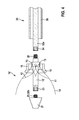
- Fig. 1 is in the uninstalled state, the first embodiment of a system according to the invention with an implant according to the invention, which is designed as a heart valve stent 10, and a catheter 30 is shown.
- the implant 10 according to the invention has a basic structure 11 which is perforated and preferably consists of a multiplicity of webs which form a mesh structure.
- the basic structure 11, which is open at both ends, has a hollow cylindrical section at its proximal end 13 and a hollow conical section at its distal end 14.
- the heart valve stent 30 preferably has three valve leaflets 12, which form the heart valve and each consist, for example, of a biological material, eg pig pericardium.
- the valve leaflets may alternatively be formed of a plastic.
- the basic structure 11 is compressed, while the basic structure 11 is present at its distal end 14 in the expanded state.
- the basic structure 11 is fastened at its outermost proximal end 13 in a ring 15.
- 11 eyelet-shaped rings or T-shaped elements are formed at the outermost proximal end 13 on the base structure, which fit into corresponding recesses of the ring 15.
- the basic structure 11 of the heart valve stent 10 which consists for example of a self-expanding material (e.g., nitinol), is disposed on a first shaft 16 formed by a hollow cylindrical tube.
- a ring 15 is fixed with recesses.
- the connection of the basic structure 11 to the first shaft 16 takes place in that the eye-shaped rings or T-shaped elements at the outermost proximal end 13 of the basic structure 11 are coupled into the corresponding recesses of the ring 15.
- a conically extending portion 17 is provided, which forms the tip of the catheter 30 after connection of the first shaft 16 with the inner shaft 22 of the catheter 20.
- the cone is arranged so that the end with the smaller diameter is located at the distal end of the first shaft 16.
- a second shaft 18 arranged on the basic structure 11 and having a second shaft 18 at its distal end has conical section 19.
- the second shaft 18 prevents the base structure 11 of a heart valve stent 10, which is made of a self-expanding material, from opening, causing it to detach from the first shaft 16.
- the first shaft 16 has a first connecting portion 20 on which, for example, an external thread is provided.
- a connecting portion 34 of the inner shaft 32 e.g. has an internal thread
- the second shaft 18 is displaced in the distal direction to crimp the base structure 11 with the flap sails 12.
- the outer shaft 36 is also moved distally over the crimped heart valve stent 10 and the second shaft 18 is removed from the instrument, for which purpose the second shaft 18 is pushed over the conical portion 17 of the first shaft 16.
- a cover 40 is provided, which preferably prevents displacement of the second shaft 18 in the proximal direction by means of a distally projecting annular portion 41, which is opposite the second shaft 18. Furthermore, the cover 40 has a threaded portion 43, which provides an internal thread. The internal thread of the threaded portion 43 can be connected to the external thread of the first connecting portion 20.
- a radially projecting pin 45 may be provided which, for example, in a corresponding Opening the base grid 11 or the ring 15 is attached. This pin 45 prevents the displacement of the second shaft 18 in the proximal direction due to its proximal arrangement to the second shaft 18.
- Fig. 4 shows the second embodiment of a system according to the invention, which in its construction substantially to the in Fig. 1 corresponds to the first embodiment shown.
- the inner shaft formed in two parts, with a proximal first part 32a and a distal second part 32b.
- the second portion 32b of the inner shaft also includes a conical portion 37 which forms the catheter tip after assembly of the system.
- the first shaft 16 of the implant according to the invention has a second connecting portion 23 which contains, for example, an internal thread.
- the second part 32b of the inner shaft accordingly provides at its proximal end a connecting portion 21 with an external thread.
- the second part 32b of the inner shaft of the catheter 30 can be connected to the first shaft 16 ', for example also by means of a bayonet closure or by means of adhesive.
- This embodiment is particularly advantageous in the case when the second shaft 18 is dimensioned so that it can not be pushed over the catheter tip (conical section 37). Accordingly, in the in Fig. 4 1, the basic structure 11 is pre-crimped with the valve leaflet 12 by means of the second shaft 18 and the outer shaft 36 is then pushed over the base grid 11. Then, the second part 32b of the inner shaft is connected to the first shaft 16 'of the heart valve stent 10 as described above.
- FIG. 5 illustrated third embodiment of a system according to the invention shows the case in which the second shaft 18 'with the outer shaft 36' and the first shaft 16 with the inner shaft 32 'are coupled.
- the heart valve stent 10 "need not be fixed by another shaft, but can be determined by the proximal outer shaft 36 '.
- the second shaft 18 ' has at its proximal end a connecting portion 24 which can be connected to the distal connecting portion 39 of the outer shaft 36'.
- the connecting portion 20 of the first shaft 16 may be connected to the distal connecting portion 34 of the inner shaft 32 '.
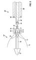
- FIG. 6 illustrated embodiment of a system according to the invention describes a constructive solution in which the catheter 30 "has three shafts, namely an inner shaft 32, an outer shaft 36 and an intermediate Fixierschaft (auxiliary shaft) 47.
- This embodiment includes the possibility that the proximal end of the heart valve stent 10 '"is fixed by the decoupled from the release unit fixing shaft 47 via a non-positive or positive mechanism on the first shaft 16.
- the fixation shaft 47 has at its distal end a connecting section 49, which can be coupled to a corresponding connecting section 24 'arranged at the proximal end of the second shaft 18 "' ,
- the second shaft 18 "' is formed to be different than can not be moved in the longitudinal direction in the above-described embodiments.
Abstract
Description
Die vorliegende Erfindung betrifft ein Implantat, insbesondere eine intraluminale Endoprothese, mit einer durchbrochenen, hohlzylinderförmigen und/oder hohlkegelförmigen Grundstruktur, wobei die Grundstruktur einen komprimierten Zustand und einen expandierten Zustand einnehmen kann. Die Erfindung betrifft ferner ein System zum Einbringen eines Implantats, vorzugsweise einer intraluminalen Endoprothese, in einen Körperhohlraum bestehend aus dem vorstehend beschriebenen Implantat und einem Katheter. Außerdem betrifft die Erfindung ein Verfahren zur Herstellung eines derartigen Systems.The present invention relates to an implant, in particular an intraluminal endoprosthesis, with a perforated, hollow cylindrical and / or hollow cone-shaped basic structure, wherein the basic structure can assume a compressed state and an expanded state. The invention further relates to a system for introducing an implant, preferably an intraluminal endoprosthesis, into a body cavity consisting of the above-described implant and a catheter. Moreover, the invention relates to a method for producing such a system.
Medizinische Implantate, insbesondere intraluminale Endoprothesen, für die unterschiedlichsten Anwendungen sind in großer Vielfalt aus dem Stand der Technik bekannt. Als Implantate im Sinne der vorliegenden Erfindung sind endovaskuläre Prothesen oder sonstige Endoprothesen, beispielsweise Stents (Gefäß-Stents (vaskuläre Stents, einschließlich Stents für die Anwendung im Bereich des Herzens und Herzklappenstents, z.B. Mitralklappen-Stent, Pulmonalklappenstent) und Gallengang-Stents), Endoprothesen zum Verschließen von persistierenden Foramen ovale (PFO), Stentgrafts zur Behandlung von Aneurysmen, Endoprothesen zum Verschließen eines ASD (Vorhofscheidewanddefekt, atrial septal defect) sowie Prothesen im Bereich des Hart- und Weichgewebes zu verstehen. Ein derartiges Implantat wird häufig mittels eines Katheters in das zu behandelnde Organ oder Gefäß eingesetzt.Medical implants, especially intraluminal endoprostheses, for a wide variety of applications are known in great variety from the prior art. Implants for the purposes of the present invention are endovascular prostheses or other endoprostheses, for example stents (vascular stents, including stents for use in the region of the heart and heart valve stents, eg mitral valve stent, pulmonary valve stent) and bile duct stents), endoprostheses for the closure of patent foramen ovale (PFO), stent grafts for the treatment of aneurysms, endoprostheses for the closure of an atrial septal defect (ASD) and hard and soft tissue prostheses. Such an implant is often inserted by means of a catheter into the organ or vessel to be treated.
Stents und andere endovaskuläre Endoprothesen weisen eine durchbrochene hohlzylinderförmige (rohrförmige) und/oder hohlkegelförmige Grundstruktur auf, die an beiden Längsenden offen ist, wobei die Grundstruktur häufig aus einer Vielzahl von Stegen zusammengesetzt ist. In einer derartige Grundstruktur können z.B. bei einem Herzklappenstent auf der Innenseite Klappensegel, beispielsweise drei Klappensegel, angeordnet sein, welche die Herzklappe ausbilden und aus einem Kunststoff oder einem biologischen Material, z.B. Schweinepericard, bestehen können. Der Stent trägt die Herzklappe und verankert diese im Herzen.Stents and other endovascular endoprostheses have a perforated hollow cylindrical (tubular) and / or hollow cone-shaped basic structure which is open at both longitudinal ends, wherein the basic structure is often composed of a plurality of Webs is composed. In such a basic structure, for example, in the case of a heart valve stent on the inside, valve leaflets, for example three valve leaflets, can be arranged, which form the heart valve and can consist of a plastic or a biological material, eg pig pericardium. The stent carries the heart valve and anchors it in the heart.
Katheter sind Röhrchen oder Schläuche verschiedenen Durchmessers, die in den jeweiligen zu behandelnden Körperhohlraum eingeführt werden können. Bei der Behandlung mit einem Katheter wird zuerst ein Führungsdraht und ggf. ein Führungskatheter in das zu behandelnde Organ oder Gefäß eingeführt. Anschließend wird der Katheter entlang des Führungsdrahts bis zu der zu behandelnden Stelle des Organs oder Gefäßes vorgeschoben, so dass das auf dem Katheter angeordnete Implantat im Bereich der zu behandelnden Stelle des Organs oder Gefäßes platziert ist. Danach wird das Implantat von dem Katheter abgekoppelt und ggf. dilatiert. Der Katheter wird dann entfernt. Gleichzeitig oder anschließend wird auch der Führungsdraht aus dem Organ oder Gefäß zurückgezogen. Für das Einbringen eines Stents wird häufig ein Katheter verwendet, welcher einen Innenschaft und einen Außenschaft besitzt.Catheters are tubes or tubes of various diameters which can be inserted into the respective body cavity to be treated. When treated with a catheter, a guidewire and, if necessary, a guiding catheter is first introduced into the organ or vessel to be treated. Subsequently, the catheter is advanced along the guidewire to the site of the organ or vessel to be treated so that the implant placed on the catheter is placed in the region of the site of the organ or vessel to be treated. Thereafter, the implant is decoupled from the catheter and possibly dilated. The catheter is then removed. Simultaneously or subsequently, the guidewire is also withdrawn from the organ or vessel. For the introduction of a stent, a catheter is often used which has an inner shaft and an outer shaft.
Stents und andere Implantate nehmen üblicherweise zwei Zustände ein, nämlich einen komprimierten Zustand mit einem kleinen Durchmesser und einen expandierten Zustand mit einem größeren Durchmesser. Im komprimierten Zustand kann das Implantat mittels eines Katheters in das zu behandelnde Gefäß oder Organ durch enge Gefäße hindurch eingeführt und an der zu behandelnden Stelle positioniert werden. Hierfür wird das Implantat beispielsweise auf den Ballon eines Katheters aufgecrimpt und so in den komprimierten Zustand überführt. Am Ort der Behandlung wird das Implantat dann beispielsweise mittels des Ballons des Katheters dilatiert und nimmt dann den expandierten Zustand ein, in dem das Implantat in dem Gefäß oder Organ verbleibt und dort festgelegt ist, nachdem der Katheter wieder aus dem Körper des Behandelten herausgezogen wurde. Alternativ nimmt ein Implantat in dem Fall, in dem seine Grundstruktur aus einem selbstexpandierenden Material (z.B. Nitinol) besteht, den komprimierten Zustand durch Komprimierung unterhalb der Übergangstemperatur und den expandierten Zustand oberhalb der Übergangstemperatur ein.Stents and other implants usually assume two states, namely a compressed state with a small diameter and an expanded state with a larger diameter. In the compressed state, the implant can be introduced through a catheter into the vessel or organ to be treated through narrow vessels and positioned at the site to be treated. For this purpose, the implant is crimped example, on the balloon of a catheter and so transferred to the compressed state. At the site of treatment, the implant is then dilated, for example by means of the balloon of the catheter and then assumes the expanded state in which the implant remains in the vessel or organ and is fixed there after the catheter has been pulled out of the body of the treated person. Alternatively, in the case where its basic structure consists of a self-expanding material (eg nitinol), an implant will assume the compressed state by compression below the transition temperature and the expanded state above the transition temperature.
Aus der Druckschrift
Bei Herzklappenstents, die mittels eines Katheters zu der zu behandelnden Stelle transportiert werden können, z.B. die CoreValve® Transkatheter Herzklappe der Fa. Medtronic GmbH, ist vor dem nicht-invasiven Eingriff zunächst eine komplizierte Montage des Stents notwendig, um diesen auf den Katheter zu montieren. Hierfür werden derzeit fünf verschiedene Hilfstools eingesetzt. Die Prozedur, die in der Regel durch den Arzt durchgeführt wird, ist sehr aufwändig und besitzt darum eine hohe Fehleranfälligkeit.For heart valve stents that can be transported by catheter to the site to be treated, e.g. The CoreValve® Transcatheter Heart Valve from Medtronic GmbH, before the non-invasive procedure initially requires a complicated assembly of the stent in order to mount it on the catheter. For this purpose, five different tools are currently used. The procedure, which is usually carried out by the doctor, is very complex and therefore has a high susceptibility to errors.
Ferner besteht das Problem, dass bei den bekannten Systemen die Stenthaltekraft ungenügend sein kann. Dies bedeutet, dass die Enden eines auf dem Katheter angeordneten Stents in einer Kurve eines Gefäßes, durch welches das System auf dem Weg zu dem zu behandelnden Körperhohlraum hindurch geführt wird, aus der Fixierung herausspringen kann. Wenn dies eintritt, können sich Ungenauigkeiten bei der Platzierung des Stents an dem zu behandelnden Ort ergeben bzw. es kann ein erneutes Crimpen oder Einfangen des Stents durch den Katheter notwendig werden, was äußerst schwierig zu bewerkstelligen ist.Further, there is the problem that in the known systems, the stent holding force may be insufficient. This means that the ends of a stent placed on the catheter can pop out of the fixation in a curve of a vessel through which the system passes on the way to the body cavity to be treated. If this occurs, inaccuracies in the placement of the stent at the site to be treated may result, or re-crimp or entrap the stent through the catheter may become necessary, which is extremely difficult to accomplish.
Die Aufgabe besteht somit darin, ein Implantat zu schaffen, welches eine Vereinfachung der Stentmontage ermöglicht. Ferner soll der Stent besser auf dem Katheter fixiert werden, um ein Herausspringen aus der Verankerung zu vermeiden. Die Aufgabe besteht außerdem darin, ein entsprechendes System aus Katheter und Implantat zu schaffen. Ferner besteht die Aufgabe darin, ein Verfahren zur Herstellung eines Systems aus Katheter und intraluminaler Endoprothese anzugeben, welches einfach durchführbar ist und ein geringes Fehlerrisiko beinhaltet.The object is therefore to provide an implant which allows a simplification of the stent assembly. Furthermore, the stent should be better fixed on the catheter to avoid jumping out of the anchorage. The task is also to provide a corresponding system of catheter and implant. Furthermore, the object is to provide a method for producing a system of catheter and intraluminal endoprosthesis, which is easy to carry out and involves a low risk of error.
Die obige Aufgabe wird durch ein Implantat mit den Merkmalen des Anspruchs 1 gelöst. Insbesondere ist bei dem erfindungsgemäßen Implantat zusätzlich ein erster rohrförmiger Schaft vorgesehen, auf dessen Außenseite die Grundstruktur des Implantats zumindest abschnittsweise im komprimierten Zustand angeordnet ist, wobei der erste Schaft einen ersten Verbindungsabschnitt aufweist, mit welchem der erste Schaft mit dem Innenschaft eines Katheters verbindbar ist.The above object is achieved by an implant having the features of claim 1. In particular, in the case of the implant according to the invention a first tubular shaft is additionally provided, on the outside of which the basic structure of the implant is arranged at least partially in the compressed state, wherein the first shaft has a first connecting portion, with which the first shaft can be connected to the inner shaft of a catheter.
Das erfindungsgemäße Implantat enthält in Form des ersten Schafts gewissermaßen bereits einen Teil des Innenschafts des Katheters, mit dem das Implantat dann zu der zu behandelnden Stelle transportiert wird. Diese Funktion füllt der erste Schaft jedoch erst dann aus, wenn der Innenschaft des Katheters mit dem ersten Schaft verbunden ist. Die Erfinder haben insbesondere erkannt, dass bei der hierdurch erfindungsgemäß realisierten Vormontage des Implantats auf einem entkoppelten distalen Innenschaft-Abschnitt (entspricht dem ersten Schaft) ein Teil der komplexen und schwierigen Arbeitsschritte bei der Initialfixierung des Implantats nicht mehr durch den Arzt durchgeführt werden muss, sondern stattdessen unter standardisierten Bedingungen bereits bei dem Hersteller erledigt werden kann. Hierdurch wird das Risiko, dass sich ein vom Arzt nicht korrekt auf dem Katheter fixiertes Implantat schwer entfaltet, minimiert. Somit werden bei der Montage beim Arzt die Anzahl der Arbeitsschritte verringert und die Arbeitsschritte vereinfacht sowie anwenderfreundlicher gestaltet. Das vormontierte Implantat kann ggf. in vorteilhafter Weise bis zu seinem Einsatz problemlos in der notwendigen Flüssigkeit gelagert werden. Vorzugsweise wird bei einem Herzklappenstent der Abschnitt, der in vormontiertem Zustand bei der Anordnung auf dem ersten Schaft komprimiert wird, am proximalen Ende des Stents ohne Klappensegel angeordnet, so dass gewährleistet ist, dass das Herklappenmaterial (Pericard oder Kunststoff) im entfalteten Zustand gelagert werden kann.The implant according to the invention, in the form of the first shaft, to a certain extent already contains part of the inner shaft of the catheter with which the implant is then transported to the site to be treated. However, this function is only completed by the first shaft when the inner shaft of the catheter is connected to the first shaft. In particular, the inventors have recognized that in the pre-assembly of the implant according to the invention on a decoupled distal inner shaft section (corresponding to the first shaft), part of the complex and difficult steps in the initial fixation of the implant need no longer be performed by the physician, but instead instead, it can be done by the manufacturer under standardized conditions. This minimizes the risk that an implant not properly fixed on the catheter by the physician will be difficult to deploy. Thus, the number of work steps are reduced during assembly at the doctor and simplifies the work steps and made user-friendly. If necessary, the preassembled implant can advantageously be stored in the necessary fluid until it is used. Preferably, in the case of a heart valve stent, the portion that is compressed in the preassembled state when placed on the first shaft is placed at the proximal end of the stent without valve leaflets, so as to ensure that the sheeting material (pericardium or plastic) can be stored in the deployed state ,
Die Verbindung mit dem Innenschaft des Katheters durch den ersten Verbindungsabschnitt des ersten Schafts kann mittels einer beliebigen kraft-, form- und/oder stoffschlüssigen Verbindung erfolgen, bspw. mit einem Bajonett-Verschluss, einem Gewinde oder einem Klebstoff. Die Verbindung kann lösbar oder nicht lösbar ausgeführt werden.The connection with the inner shaft of the catheter through the first connecting portion of the first shaft can be effected by means of any force, shape and / or material connection, for example. With a bayonet closure, a thread or an adhesive. The compound can be made detachable or non-detachable.
In einem Ausführungsbeispiel ist zu dem Implantat ein zweiter, zumindest abschnittsweise rohrförmigen Schaft vorgesehen, der die Grundstruktur umgebend angeordnet ist, vorzugsweise an ihrem proximalen Ende. Vorzugsweise umgibt der zweite Schaft die Grundstruktur in dem Abschnitt, in dem das Implantat im komprimierten Zustand auf dem ersten Schaft angeordnet ist. Mittels des zweiten Schafts erfolgt die Fixierung des Implantats auf dem ersten Schaft durch den Hersteller bzw., nach der Verbindung des ersten Schafts mit dem Innenschaft des Katheters, auf dem Katheter. Hierdurch wird eine erhöhte Implantat-Haltekraft erreicht, so dass das Implantat in einer Gefäßkurve besser auf dem Katheter fixiert ist und nicht herausspringt. Dadurch ist das Implantat präziser am Ort der Behandlung platzierbar und ein erneutes Crimpen oder Einfangen des Implantats ist nicht notwendig. Der zweite Schaft kann alternativ auch zum Vorcrimpen der Grundstruktur des Implantats vor der Fixierung mit einem Außenschaft verwendet werden.In one embodiment, a second, at least partially tubular shaft is provided to the implant, which is arranged surrounding the basic structure, preferably at its proximal end. The second shaft preferably surrounds the basic structure in the section in which the implant is arranged on the first shaft in the compressed state. By means of the second shaft, the fixation of the implant on the first shaft by the manufacturer or, after the connection of the first shaft with the inner shaft of the catheter, on the catheter. As a result, an increased implant holding force is achieved, so that the implant is better fixed in a vessel curve on the catheter and does not pop out. As a result, the implant can be placed more precisely at the site of the treatment and a renewed crimping or capture of the implant is not necessary. Alternatively, the second shaft can also be used to pre-crimp the basic structure of the implant prior to fixation with an outer shaft.
In einer Weiterbildung der Erfindung ist vorgesehen, dass zusätzlich Mittel zur Fixierung des zweiten Schafts in proximaler Richtung vorgesehen sind, beispielsweise ein proximal angeordneter Deckel oder ein am proximalen Ende des zweiten Schafts angeordneter, in radialer Richtung vorstehender Pin. Durch das Grundgitter des Implantats wird nämlich auf den zweiten Schaft eine Kraft ausgeübt, welche zu einer Verschiebung des Schafts in proximaler Richtung führt. Der zweite Schaft kann hierdurch von dem Implantat rutschen. Die Mittel zur Fixierung, z.B. ein Deckel oder ein in radialer Richtung vorstehender Pin, der am proximalen Ende des zweiten Schafts angeordnet ist, wirken der von dem Grundgitter auf den zweiten Schaft ausgeübten Kraft entgegen. Weitere reversible form- oder kraftschlüssige Techniken kommen für diese Fixierung ebenfalls in Frage.In a further development of the invention it is provided that in addition means for fixing the second shaft in the proximal direction are provided, for example, a proximally arranged cover or arranged at the proximal end of the second shaft, in the radial direction projecting pin. Because of the base grid of the implant, a force is exerted on the second shaft, which leads to a displacement of the shaft in the proximal direction. The second shaft can thereby slip off the implant. The means for fixation, e.g. a cover or radially projecting pin located at the proximal end of the second shaft counteracts the force exerted by the base grid on the second shaft. Other reversible positive or non-positive techniques are also suitable for this fixation.
Es ist in einem weiteren Ausführungsbeispiel vorgesehen, dass der zweite Schaft einen konischen Abschnitt aufweist, der vorzugsweise am distalen Ende des zweiten Schafts angeordnet ist. Durch diesen Abschnitt kann bei der Montage des Implantats das auf der distalen Seite des zweiten Schafts angeordnete Teil des Grundgitters besser gecrimpt werden.It is provided in a further embodiment that the second shaft has a conical portion, which is preferably arranged at the distal end of the second shaft. Through this section, during assembly of the implant, the part of the base grid arranged on the distal side of the second shaft can be better crimped.
Es ist weiter von Vorteil, wenn der zweite Schaft einen Verbindungsabschnitt aufweist, mit dem der zweite Schaft mit einem rohrförmigen Außenschaft oder einem rohrförmigen Fixierschaft (Hilfsschaft) des Katheters verbindbar ist. Die Verbindung mit dem Außenschaft oder dem Fixierschaft des Katheters kann prinzipiell durch jede beliebige kraft, form- oder stoffschlüssige Verbindung gebildet werden und sie kann entweder lösbar oder nicht lösbar ausgestaltet sein. Bei diesem Ausführungsbeispiel erfolgt das Crimpen während der Montage des Implantats durch Verschieben des Außenschafts in distaler Richtung. Der ggf. zusätzlich vorgesehene, zwischen Innenschaft und Außenschaft angeordnete Fixierschaft dient dazu, das Implantat an der gewünschten Stelle auf dem Innenschaft des Katheters bzw. dem ersten Schaft losgelöst vom Außenschaft, d.h. eigenständig zu halten, auch wenn bei dem Transportieren zu der zu behandelnden Stelle im Körper Kurven in den Gefäßen zu überwinden sind. Die Fixierung der Grundstruktur durch den Fixierschaft kann nach erfolgreicher Platzierung des Implantats an der gewünschten Stelle z.B. durch den behandelnden Arzt in einem separaten Schritt, d.h. losgelöst vom Außenschaft, gelöst werden.It is also advantageous if the second shaft has a connecting portion, with which the second shaft with a tubular outer shaft or a tubular Fixierschaft (auxiliary shaft) of the catheter is connectable. The connection with the outer shaft or the fixation of the catheter can in principle be formed by any force, positive or cohesive connection and it can be designed either detachable or non-detachable. In this embodiment, crimping occurs during assembly of the implant by displacing the outer shaft in the distal direction. The possibly additionally provided between the inner shaft and outer shaft arranged fixing shaft serves to hold the implant at the desired location on the inner shaft of the catheter or the first shaft detached from the outer shaft, ie independently, even if transported to the site to be treated in the body curves in the vessels are overcome. The fixation of the basic structure by the fixation can be solved after successful placement of the implant at the desired location, for example by the attending physician in a separate step, ie detached from the outer shaft.
Bei der Montage des Implantats auf dem Katheter besteht ferner das Problem, dass die Spitze des Katheters einen so großen Außendurchmesser aufweisen kann, dass ein Hilfsrohr z.B. in Form eines zweiten Schafts zum Crimpen nicht über die Spitze geschoben werden kann. In diesem Fall ist es von Vorteil, wenn der Innenschaft des Katheters zweiteilig gestaltet ist und entsprechend der erste Schaft, vorzugsweise an seinem distalen Ende, einen zweiten Verbindungsabschnitt aufweist, mit welchem der erste Schaft mit der distalen Spitze des Innenschafts eines Katheters verbindbar ist. Dann erfolgt die Verbindung des ersten Schafts mit der Katheterspitze bzw. dem zweiten Teil des Innenschafts erst nach dem Crimpen. Auch die Verbindung zwischen dem zweiten Verbindungsabschnitt des ersten Schafts und dem zweiten Teil des Innenschafts des Katheters kann wieder als jede beliebige kraft-, form- und/oder stoffschlüssige Verbindung ausgebildet sein, welche lösbar oder nicht lösbar ausgeführt werden kann.When mounting the implant on the catheter, there is also the problem that the tip of the catheter may have such a large outer diameter that an auxiliary tube is e.g. in the form of a second shaft for crimping can not be pushed over the top. In this case, it is advantageous if the inner shaft of the catheter is designed in two parts and corresponding to the first shaft, preferably at its distal end, a second connecting portion, with which the first shaft with the distal tip of the inner shaft of a catheter is connectable. Then, the connection of the first shaft with the catheter tip or the second part of the inner shaft takes place only after crimping. Also, the connection between the second connecting portion of the first shaft and the second part of the inner shaft of the catheter may be formed again as any force, positive and / or cohesive connection, which can be made detachable or non-detachable.
Die obige Aufgabe wird mit den oben angegebenen Vorteilen außerdem durch ein System zum Einbringen eines Implantats gelöst, bei dem der Innenschaft des Katheters einen, vorzugsweise an seinem distalen Ende angeordneten Verbindungsabschnitt aufweist, mit dem der Innenschaft mit dem ersten Schaft des Implantats verbindbar ist. Hierbei entspricht das Implantat einer der oben angegebenen Ausführungsformen.The above object is also achieved with the above-mentioned advantages by a system for introducing an implant, wherein the inner shaft of the catheter has a, preferably at its distal end arranged connecting portion with which the inner shaft with the first shaft of the implant is connectable. Here, the implant corresponds to one of the embodiments given above.
Die Vorteile des erfindungsgemäßen Systems sind oben bereits im Zusammenhang mit dem erfindungsgemäßen Implantat erläutert worden.The advantages of the system according to the invention have already been explained above in connection with the implant according to the invention.
In einem bevorzugten Ausführungsbeispiel weist der Außenschaft des Katheters oder der Fixierschaft des Katheters jeweils einen, vorzugsweise an dem jeweiligen distalen Ende angeordneten, Verbindungsabschnitt auf, mit dem der Außenschaft bzw. der Fixierschaft mit dem zweiten Schaft des Implantats verbindbar ist. Wie oben bereits erläutert wurde, kann der Fixierschaft des Katheters zur eigenständigen Fixierung des Implantats verwendet werden.In a preferred embodiment, the outer shaft of the catheter or of the fixation shaft of the catheter in each case has a connecting section, preferably arranged at the respective distal end, with which the outer shaft or the fixation shaft can be connected to the second shaft of the implant. As already explained above, the fixation shaft of the catheter can be used for the independent fixation of the implant.
Weiter bevorzugt ist der Innenschaft des Katheters zweiteilig ausgebildet, wobei der erste Teil durch einen proximalen Abschnitt und der zweite Teil durch einen distalen Abschnitt des Innenschafts gebildet ist. Der distale Abschnitt enthält insbesondere die Katheterspitze, welche hinsichtlich des Einführens des erfindungsgemäßen Systems in den Körper von besonderer Bedeutung ist, da sie nach dem Führungsdraht das erste Element des Katheters darstellt, welches in den Körper eindringt und sich in führender Position während der Bewegung des Katheters durch den Körper befindet.More preferably, the inner shaft of the catheter is formed in two parts, wherein the first part is formed by a proximal portion and the second part by a distal portion of the inner shaft. In particular, the distal portion contains the catheter tip, which is of particular importance in terms of introducing the system of the invention into the body, as it constitutes, after the guidewire, the first member of the catheter which penetrates the body and is in a leading position during movement of the catheter located by the body.
Die obige Aufgabe wird außerdem gelöst durch ein Verfahren, bei dem vor dem Einbringen des Systems in einen Körperhohlraum eines Menschen oder Tiers der erste Verbindungsabschnitt des ersten Schafts mit dem gegenüber liegenden Verbindungsabschnitt des Innenschafts des Katheters verbunden wird. Dieses Verfahren stellt eine einfache Möglichkeit zur Herstellung eines Systems bestehend aus einem Katheter und einem Implantat dar. Das erfindungsgemäße Verfahren beinhaltet auf Seiten des Arztes weniger Arbeitsschritte als das herkömmliche Verfahren und erleichtert damit insbesondere dessen Tätigkeit vor einer Implantation. Nach der Verbindung des ersten Schafts mit dem Innenschaft des Katheters kann danach der Grundkörper beispielsweise mittels eines zweiten Schafts, der nach distal vorgeschoben wird, vorgecrimpt werden. Der Außenschaft, welcher ggf. unmittelbar proximal hinter dem zweiten Schaft folgt, wird anschließend über das Implantat geführt. Danach wird der zweite Schaft distal über die Katheterspitze geschoben und vom Instrument entfernt. Weitere Ausführungsformen werden unten in den Ausführungsbeispielen erläutert.The above object is also achieved by a method in which prior to the introduction of the system into a body cavity of a human or animal, the first connecting portion of the first shaft is connected to the opposite connecting portion of the inner shaft of the catheter. This method represents a simple possibility for the production of a system consisting of a catheter and an implant. The method according to the invention involves fewer work steps on the part of the physician than the conventional method and thus facilitates in particular its activity before implantation. After connecting the first shaft to the inner shaft of the catheter, the base body may then be pre-crimped, for example by means of a second shaft which is advanced distally. The outer shaft, which optionally follows immediately proximal behind the second shaft, is then guided over the implant. Thereafter, the second shaft is distally over the The catheter tip is pushed and removed from the instrument. Further embodiments are explained below in the embodiments.
Bei einer zweiteiligen Ausbildung des Innenschafts wird vor dem Einbringen des Systems in einen Körperhohlraum eines Menschen oder Tiers der erste Verbindungsabschnitt des ersten Schafts mit dem gegenüber liegenden Verbindungsabschnitts des ersten Teils des Innenschafts des Katheters und der zweite Verbindungsschaft des ersten Schafts mit dem gegenüberliegenden Verbindungsabschnitt des zweiten Teils des Innenschafts des Katheters verbunden. Wie bereits oben erläutert wurde, ist diese Ausführungsform insbesondere dann von Bedeutung, wenn ein zweiter Schaft zum Vorcrimpen des Implantats derart dimensioniert ist, dass der jeweilige Schaft nicht über die Katheterspitze geschoben werden kann. In diesem Fall wird nach der Verbindung des ersten Teils des Innenschafts mit dem ersten Schaft zuerst das Grundgitter mittels zweiten Schafts vorgecrimpt und anschließend vom Implantat entfernt. Danach wird der zweite Teil des Innenschafts mit dem zweiten Verbindungsabschnitt des ersten Schafts verbunden.In a two-part embodiment of the inner shaft, prior to insertion of the system into a human or animal body cavity, the first connecting portion of the first shaft with the opposite connecting portion of the first portion of the inner shaft of the catheter and the second connecting shaft of the first shaft with the opposite connecting portion of the second Part of the inner shaft of the catheter connected. As already explained above, this embodiment is of particular importance when a second shaft for pre-crimping the implant is dimensioned such that the respective shaft can not be pushed over the catheter tip. In this case, after the connection of the first part of the inner shaft with the first shaft, the basic grid is first pre-crimped by means of the second shaft and then removed from the implant. Thereafter, the second part of the inner shaft is connected to the second connecting portion of the first shaft.
Es ist ferner von Vorteil, wenn der Verbindungsabschnitt des zweiten Schafts mit dem gegenüber liegenden Verbindungsabschnitt des Außenschafts des Katheters oder mit dem gegenüber liegenden Verbindungsabschnitt des Fixierschafts des Katheters verbunden wird. Im ersten Fall wird der Außenschaft des Katheters sowie der mit diesem vorab verbundene zweite Schaft zum Crimpen des Grundgitters verwendet, während im zweiten Fall eine Fixierung des Grundgitters durch den zweiten Schaft erfolgt.It is also advantageous if the connecting portion of the second shaft is connected to the opposite connecting portion of the outer shaft of the catheter or to the opposite connecting portion of the fixing of the catheter. In the first case, the outer shaft of the catheter and the second shaft connected in advance with it are used for crimping the base lattice, while in the second case the base lattice is immobilized by the second shaft.
Weitere Ziele, Merkmale, Vorteile und Anwendungsmöglichkeiten der Erfindung ergeben sich aus der nachfolgenden Beschreibung von Ausführungsbeispielen zu der Erfindung anhand der Figuren. Dabei bilden alle beschriebenen und/oder bildlich dargestellten Merkmale für sich oder in beliebiger Kombination den Gegenstand der vorliegenden Erfindung, auch unabhängig von ihrer Zusammenfassung in den einzelnen Ansprüchen oder deren Rückbeziehung.Other objects, features, advantages and applications of the invention will become apparent from the following description of exemplary embodiments of the invention with reference to FIGS. All described and / or illustrated features alone or in any combination form the subject matter of the present invention, also independent of their summary in the individual claims or their dependency.
Es zeigen schematisch:
- Fig. 1
- ein erstes Ausführungsbeispiel eines erfindungsgemäßen Systems mit einem ersten Ausführungsbeispiel eines erfindungsgemäßen Implantats im Querschnitt,
- Fig. 2
- ein zweites Ausführungsbeispiel eines erfindungsgemäßen Implantats im Querschnitt,
- Fig. 3
- ein drittes Ausführungsbeispiel eines erfindungsgemäßen Implantats im Querschnitt,
- Fig. 4
- ein zweites Ausführungsbeispiels eines erfindungsgemäßen Systems mit einem vierten Ausführungsbeispiel eines erfindungsgemäßen Implantats im Querschnitt,
- Fig. 5
- ein drittes Ausführungsbeispiels eines erfindungsgemäßen Systems mit einem fünften Ausführungsbespiel eines erfindungsgemäßen Implantats im Querschnitt und
- Fig. 6
- ein viertes Ausführungsbeispiel eines erfindungsgemäßen Systems mit einem sechsten Ausführungsbeispiel eines erfindungsgemäßen Implantats, ebenfalls jeweils im Querschnitt.
- Fig. 1
- A first embodiment of a system according to the invention with a first embodiment of an implant according to the invention in cross-section,
- Fig. 2
- A second embodiment of an implant according to the invention in cross-section,
- Fig. 3
- A third embodiment of an implant according to the invention in cross-section,
- Fig. 4
- A second embodiment of a system according to the invention with a fourth embodiment of an implant according to the invention in cross-section,
- Fig. 5
- a third embodiment of a system according to the invention with a fifth embodiment of an implant according to the invention in cross section and
- Fig. 6
- A fourth embodiment of a system according to the invention with a sixth embodiment of an implant according to the invention, also in each case in cross section.
Die Figuren zeigen die Ausführungsbeispiele schematisch und vereinfacht und stellen insbesondere die Details dar, die wichtig sind, um die Erfindung zu verstehen. Für die Erfindung unbedeutende Details wurden teilweise weggelassen. Weiterhin bedeutet die Bezeichnung "distales Ende" im Zusammenhang mit der vorliegenden Erfindung das Ende des Implantats oder des Katheters, das während dem Einbringen des Implantats in den Körper von dem behandelnden Arzt weg zeigt, während das "proximale Ende" zu der den Katheter bedienenden Person hin zeigt.The figures show the embodiments schematically and simplified and in particular represent the details that are important to understand the invention. For the invention insignificant details have been partially omitted. Furthermore, the term "distal end" in the context of the present invention means the end of the implant or catheter pointing away from the attending physician during insertion of the implant into the body while the "proximal end" is toward the person operating the catheter shows.
In
Die Grundstruktur 11 des Herzklappenstents 10, welche beispielsweise aus einem selbstexpandierenden Material (z.B. Nitinol) besteht, ist auf einem ersten Schaft 16 angeordnet, welcher durch einen hohlzylinderförmigen Schlauch gebildet wird. Im proximalen Abschnitt des ersten Schafts 16 ist ein Ring 15 mit Aussparungen fixiert. Die Anbindung der Grundstruktur 11 an den ersten Schaft 16 erfolgt dadurch, dass die ösenförmigen Ringe oder T-förmigen Elemente am äußersten proximalen Ende 13 der Grundstruktur 11 in die entsprechenden Aussparungen des Rings 15 gekoppelt werden. Am distalen Ende des ersten Schafts 16 ist ein konisch verlaufender Abschnitt 17 vorgesehen, welcher nach Verbindung des ersten Schafts 16 mit dem Innenschaft 22 des Katheters 20 die Spitze des Katheters 30 ausbildet. Hierfür ist der Konus so angeordnet, dass das Ende mit dem geringeren Durchmesser an dem distalen Ende des ersten Schafts 16 liegt.The
An dem proximalen Ende 13 der Grundstruktur 11 ist ferner ein auf der Grundstruktur 11 angeordneter zweiter Schaft 18 vorgesehen, welcher an seinem distalen Ende einen konischen Abschnitt 19 aufweist. Der zweite Schaft 18 hindert beispielsweise die aus einem selbstexpandieren Material bestehende Grundstruktur 11 eines Herzklappenstents 10 daran, sich zu öffnen, wodurch diese sich vom ersten Schaft 16 ablösen würde. An seinem proximalen Ende besitzt der erste Schaft 16 einen ersten Verbindungsabschnitt 20, an welchem beispielsweise ein Außengewinde vorgesehen ist.At the
Bei der Montage des Systems wird der Katheter 30, d.h. insbesondere ein Verbindungsabschnitt 34 des Innenschafts 32, der z.B. ein Innengewinde aufweist, mit dem Außengewinde des ersten Verbindungsabschnitts 20 des ersten Schafts derart in Eingriff gebracht, dass der Innenschaft 32 des Katheters 30 mit dem ersten Schaft 16 des Implantats verbunden ist. Anschließend wird der zweite Schaft 18 in distaler Richtung verschoben, um die Grundstruktur 11 mit den Klappensegeln 12 zu crimpen. Danach wird der Außenschaft 36 über den gecrimpten Herzklappenstent 10 ebenfalls in distaler Richtung bewegt und der zweite Schaft 18 von dem Instrument entfernt, wobei hierzu der zweite Schaft 18 über den konischen Abschnitt 17 des ersten Schafts 16 geschoben wird.When mounting the system, the
Als alternative Möglichkeiten, den ersten Schaft 16 und den Innenschaft 32 des Katheters 30 in den jeweiligen Verbindungsabschnitten 20, 43 miteinander zu verbinden, kommen z.B. auch die Verwendung eines Bajonettverschlusses oder von Klebstoff (Sekundenkleber) in Frage.As alternative ways of interconnecting the
Um zu verhindern, dass der zweite Schaft 18 in proximaler Richtung von der Grundstruktur 11 abfällt, ist bei der in
Alternativ kann, wie in
Dieses Ausführungsbeispiel ist insbesondere für den Fall vorteilhaft, wenn der zweite Schaft 18 so dimensioniert ist, dass er nicht über die Katheterspitze (konischer Abschnitt 37) geschoben werden kann. Entsprechend wird bei dem in
Das in
Das in
Bei der Kopplung des ersten Schafts 16 des Implantats 10"' an den Katheter 30" über einen im Zusammenhang mit
Dieses Ausführungsbeispiel ist besonders vorteilhaft hinsichtlich der Fixierung des Stents, da das Stentende in der Kurve nicht mehr aus der Fixierung springen kann. Hierdurch wird eine genaue Platzierung des Herzklappenstents 10'" ermöglicht. Zur Fixierung des Herzklappenstents weist der Fixierschaft 47 an seinem distalen Ende einen Verbindungsabschnitt 49 auf, welcher mit einem entsprechenden, am proximalen Ende des zweiten Schafts 18"' angeordneten Verbindungsabschnitt 24' gekoppelt werden kann. Bei diesem Ausführungsbeispiel ist der zweite Schaft 18"' derart ausgebildet, dass er anders als bei den oben erläuterten Ausführungsbeispielen nicht in longitudinaler Richtung verschoben werden kann.This embodiment is particularly advantageous in terms of the fixation of the stent, since the stent end in the curve can not jump out of the fixation. In order to fix the heart valve stent, the
- 10, 10', 10", 10'"10, 10 ', 10 ", 10'"
- HerzklappenstentHeart valve stent
- 1111
- Grundstrukturbasic structure
- 1212
- Klappensegelleaflets
- 1313
-
proximales Ende der Grundstruktur 11proximal end of the
basic structure 11 - 1414
-
distales Ende der Grundstruktur 11distal end of the
basic structure 11 - 1515
- Ringring
- 16, 16'16, 16 '
- erster Schaftfirst shaft
- 1717
-
konischer Abschnitt des ersten Schafts 16conical section of the
first shaft 16 - 18, 18', 18", 18""18, 18 ', 18 ", 18" "
- zweiter Schaftsecond shaft
- 1919
-
konischer Abschnitt des zweiten Schafts 18conical section of the
second shaft 18 - 2020
-
erster Verbindungsabschnitt des ersten Schafts 16, 16'first connecting portion of the
first shaft 16, 16 ' - 2121
- Verbindungsabschnitt des zweiten Teils 32b des InnenschaftsConnecting portion of the second part 32b of the inner shaft
- 2323
- zweiter Verbindungsabschnitt des ersten Schafts 16'second connecting portion of the first shaft 16 '
- 24, 24'24, 24 '
-
Verbindungsabschnitt des zweiten Schafts 18', 18", 18"'Connecting portion of the
second shaft 18 ', 18 ", 18"' - 30, 30', 30"30, 30 ', 30 "
- Kathetercatheter
- 32, 32'32, 32 '
- Innenschaftinner shaft
- 32a32a
- erster Teil des Innenschaftsfirst part of the inner shaft
- 32b32b
- zweiter Teil des Innenschaftssecond part of the inner shaft
- 3434
- erster Verbindungsabschnitt des Innenschafts 32first connecting portion of the inner shaft 32nd
- 36,36'36.36 '
- Außenschaftouter shaft
- 3737
- konischer Abschnitt des zweiten Teils 32b des Innenschafts 32Conical section of the second part 32 b of the inner shaft 32nd
- 3939
- Verbindungsabschnitt des Außenschafts 36'Connecting portion of the outer shaft 36 '
- 4040
- Deckelcover
- 4141
- vorstehender Ringprotruding ring
- 4343
- Verbindungsabschnitt des Deckels 40Connecting portion of the lid 40th
- 4545
- PinPin code
- 4747
- Fixierschaftfixing shaft
- 4949
- Verbindungsabschnitt des Fixierschafts 47Connecting portion of the fixing 47th
Claims (12)
Applications Claiming Priority (1)
| Application Number | Priority Date | Filing Date | Title |
|---|---|---|---|
| US201261703278P | 2012-09-20 | 2012-09-20 |
Publications (2)
| Publication Number | Publication Date |
|---|---|
| EP2710985A2 true EP2710985A2 (en) | 2014-03-26 |
| EP2710985A3 EP2710985A3 (en) | 2016-01-13 |
Family
ID=48998469
Family Applications (1)
| Application Number | Title | Priority Date | Filing Date |
|---|---|---|---|
| EP13180502.0A Withdrawn EP2710985A3 (en) | 2012-09-20 | 2013-08-15 | Implant, system formed of an implant and a catheter, and method for producing such a system |
Country Status (2)
| Country | Link |
|---|---|
| US (1) | US9198781B2 (en) |
| EP (1) | EP2710985A3 (en) |
Cited By (2)
| Publication number | Priority date | Publication date | Assignee | Title |
|---|---|---|---|---|
| WO2016037778A1 (en) * | 2014-09-12 | 2016-03-17 | Pfm Medical Ag | Device for inserting a medical implant into a human or animal body |
| WO2021104854A1 (en) * | 2019-11-27 | 2021-06-03 | Medtronic CV Luxembourg S.a.r.l. | Integrated loading and storage system for implantable medical devices |
Families Citing this family (11)
| Publication number | Priority date | Publication date | Assignee | Title |
|---|---|---|---|---|
| US10376363B2 (en) | 2015-04-30 | 2019-08-13 | Edwards Lifesciences Cardiaq Llc | Replacement mitral valve, delivery system for replacement mitral valve and methods of use |
| EP3225218A1 (en) * | 2016-03-30 | 2017-10-04 | Biotronik AG | Catheter device with an implant capsule attached to the external shaft by means of tabs |
| CN107550524B (en) * | 2016-07-01 | 2020-01-03 | 先健科技(深圳)有限公司 | Conveying device |
| US10653523B2 (en) | 2017-01-19 | 2020-05-19 | 4C Medical Technologies, Inc. | Systems, methods and devices for delivery systems, methods and devices for implanting prosthetic heart valves |
| US10561495B2 (en) | 2017-01-24 | 2020-02-18 | 4C Medical Technologies, Inc. | Systems, methods and devices for two-step delivery and implantation of prosthetic heart valve |
| WO2018145249A1 (en) * | 2017-02-07 | 2018-08-16 | 上海甲悦医疗器械有限公司 | Device for treating regurgitation of tricuspid valve and implantation method therefor |
| US10786234B2 (en) * | 2017-03-27 | 2020-09-29 | Arthrex, Inc. | Suture anchor assembly with universal inserter device |
| US11857441B2 (en) | 2018-09-04 | 2024-01-02 | 4C Medical Technologies, Inc. | Stent loading device |
| EP3870113A1 (en) * | 2018-10-25 | 2021-09-01 | Cephea Valve Technologies, Inc. | Cardiac valve loading devices and systems |
| US20200375733A1 (en) * | 2019-05-30 | 2020-12-03 | 4C Medical Technologies, Inc. | Devices, systems and methods for collapsible and expandable implant loading, transseptal delivery, positioning deployment and repositioning deployment |
| US11931253B2 (en) | 2020-01-31 | 2024-03-19 | 4C Medical Technologies, Inc. | Prosthetic heart valve delivery system: ball-slide attachment |
Citations (1)
| Publication number | Priority date | Publication date | Assignee | Title |
|---|---|---|---|---|
| US8029564B2 (en) | 2002-01-02 | 2011-10-04 | Medtronic, Inc. | Prosthetic heart valve system |
Family Cites Families (15)
| Publication number | Priority date | Publication date | Assignee | Title |
|---|---|---|---|---|
| DE9010130U1 (en) * | 1989-07-13 | 1990-09-13 | American Medical Systems, Inc., Minnetonka, Minn., Us | |
| US5928258A (en) * | 1997-09-26 | 1999-07-27 | Corvita Corporation | Method and apparatus for loading a stent or stent-graft into a delivery sheath |
| US6019778A (en) * | 1998-03-13 | 2000-02-01 | Cordis Corporation | Delivery apparatus for a self-expanding stent |
| WO1999062428A1 (en) * | 1998-06-04 | 1999-12-09 | Scimed Life Systems, Inc. | Stent loading tool |
| US6090035A (en) * | 1999-03-19 | 2000-07-18 | Isostent, Inc. | Stent loading assembly for a self-expanding stent |
| US8292943B2 (en) * | 2003-09-03 | 2012-10-23 | Bolton Medical, Inc. | Stent graft with longitudinal support member |
| US7867268B2 (en) * | 2003-09-24 | 2011-01-11 | Boston Scientific Scimed, Inc. | Stent delivery system for self-expanding stent |
| US8535368B2 (en) * | 2006-05-19 | 2013-09-17 | Boston Scientific Scimed, Inc. | Apparatus for loading and delivering a stent |
| US8348995B2 (en) * | 2006-09-19 | 2013-01-08 | Medtronic Ventor Technologies, Ltd. | Axial-force fixation member for valve |
| US8608792B2 (en) * | 2007-11-30 | 2013-12-17 | Scitech Produtos Medicos Ltda | Endoprosthesis and delivery system for delivering the endoprosthesis within a vessel of a patient |
| US9149358B2 (en) * | 2008-01-24 | 2015-10-06 | Medtronic, Inc. | Delivery systems for prosthetic heart valves |
| US20090276027A1 (en) * | 2008-05-01 | 2009-11-05 | Medtronic Vasscular, Inc. | Stent Graft Delivery System and Method of Use |
| AU2010236288A1 (en) * | 2009-04-15 | 2011-10-20 | Cardiaq Valve Technologies, Inc. | Vascular implant and delivery system |
| US8585019B2 (en) * | 2009-08-20 | 2013-11-19 | Cook Medical Technologies Llc | Loading apparatus and system for expandable intraluminal medical devices |
| US9414914B2 (en) * | 2010-02-24 | 2016-08-16 | Medtronic Ventor Technologies Ltd. | Catheter assembly with valve crimping accessories |
-
2013
- 2013-08-15 EP EP13180502.0A patent/EP2710985A3/en not_active Withdrawn
- 2013-09-09 US US14/021,937 patent/US9198781B2/en not_active Expired - Fee Related
Patent Citations (1)
| Publication number | Priority date | Publication date | Assignee | Title |
|---|---|---|---|---|
| US8029564B2 (en) | 2002-01-02 | 2011-10-04 | Medtronic, Inc. | Prosthetic heart valve system |
Cited By (3)
| Publication number | Priority date | Publication date | Assignee | Title |
|---|---|---|---|---|
| WO2016037778A1 (en) * | 2014-09-12 | 2016-03-17 | Pfm Medical Ag | Device for inserting a medical implant into a human or animal body |
| WO2021104854A1 (en) * | 2019-11-27 | 2021-06-03 | Medtronic CV Luxembourg S.a.r.l. | Integrated loading and storage system for implantable medical devices |
| US11284985B2 (en) | 2019-11-27 | 2022-03-29 | Medtronic CV Luxembourg S.a.r.l. | Integrated loading and storage system for implantable medical devices |
Also Published As
| Publication number | Publication date |
|---|---|
| US9198781B2 (en) | 2015-12-01 |
| EP2710985A3 (en) | 2016-01-13 |
| US20140081375A1 (en) | 2014-03-20 |
Similar Documents
| Publication | Publication Date | Title |
|---|---|---|
| EP2710985A2 (en) | Implant, system formed of an implant and a catheter, and method for producing such a system | |
| DE102012101103B3 (en) | Stentgraft with fixation elements and insertion system | |
| EP2786726B1 (en) | Catheter for transvascular implantation of heart valve prosthetics | |
| DE60309843T2 (en) | DEVICE FOR ANCHORING ENDOLUMINAL PROTESTS | |
| EP3213717B1 (en) | Delivery catheter and catheter arrangement | |
| EP2262451B1 (en) | Stent, which can be decreased in diameter again in a controlled manner from the expanded state | |
| EP0592726B1 (en) | Catheter with a vessel support | |
| DE60031381T2 (en) | A SINGLE PUNCTION REQUIRING DEFENSE SYSTEM FOR A VENTILATION IMPLANT PLANT | |
| DE69732411T2 (en) | Repair of body vessels by prostheses | |
| EP2809265B1 (en) | Modular stent graft | |
| EP3178450B1 (en) | Insertion catheter and catheter assembly | |
| DE102010008360A1 (en) | Medical implant in which gaps remain during crimping or folding, method and device for moving | |
| EP3897454B1 (en) | Device for feeding and setting an implant into a blood vessel | |
| WO2014026870A9 (en) | Implantable device for use in the human and/or animal body to replace an organ valve | |
| EP3203931B1 (en) | Vascular prosthesis system | |
| DE102010008382A1 (en) | A method of crimping or folding a medical implant on a device for introducing or introducing same using zero-pressure crimping and devices | |
| DE102006058186A1 (en) | Proximal fixation | |
| DE102004062296A1 (en) | Device for positioning a stent | |
| EP2754425A1 (en) | Device and method for crimping an implant | |
| DE102013104565B3 (en) | Pusher assembly for a delivery system for a self-expanding vascular graft and a delivery system | |
| EP3473212A1 (en) | System comprising catheter and heart valve prosthetic | |
| EP2385806A1 (en) | Device having a unit that can be implanted into a vessel of the body of a patient and a lining and method for the production thereof | |
| EP3130316A1 (en) | Insertion catheter, catheter sheath and catheter assembly | |
| WO2021023545A1 (en) | Implant having a three-dimensional structure | |
| WO2023083686A1 (en) | Stent with releasable stent sections |
Legal Events
| Date | Code | Title | Description |
|---|---|---|---|
| PUAI | Public reference made under article 153(3) epc to a published international application that has entered the european phase |
Free format text: ORIGINAL CODE: 0009012 |
|
| AK | Designated contracting states |
Kind code of ref document: A2 Designated state(s): AL AT BE BG CH CY CZ DE DK EE ES FI FR GB GR HR HU IE IS IT LI LT LU LV MC MK MT NL NO PL PT RO RS SE SI SK SM TR |
|
| AX | Request for extension of the european patent |
Extension state: BA ME |
|
| PUAL | Search report despatched |
Free format text: ORIGINAL CODE: 0009013 |
|
| AK | Designated contracting states |
Kind code of ref document: A3 Designated state(s): AL AT BE BG CH CY CZ DE DK EE ES FI FR GB GR HR HU IE IS IT LI LT LU LV MC MK MT NL NO PL PT RO RS SE SI SK SM TR |
|
| AX | Request for extension of the european patent |
Extension state: BA ME |
|
| RIC1 | Information provided on ipc code assigned before grant |
Ipc: A61F 2/24 20060101ALI20151204BHEP Ipc: A61F 2/966 20130101AFI20151204BHEP |
|
| STAA | Information on the status of an ep patent application or granted ep patent |
Free format text: STATUS: THE APPLICATION IS DEEMED TO BE WITHDRAWN |
|
| 18D | Application deemed to be withdrawn |
Effective date: 20160714 |