EP2733018A1 - Folding vehicle rear view mirrors - Google Patents
Folding vehicle rear view mirrors Download PDFInfo
- Publication number
- EP2733018A1 EP2733018A1 EP20130185500 EP13185500A EP2733018A1 EP 2733018 A1 EP2733018 A1 EP 2733018A1 EP 20130185500 EP20130185500 EP 20130185500 EP 13185500 A EP13185500 A EP 13185500A EP 2733018 A1 EP2733018 A1 EP 2733018A1
- Authority
- EP
- European Patent Office
- Prior art keywords
- arm means
- arms
- mirror
- pair
- mounting bracket
- Prior art date
- Legal status (The legal status is an assumption and is not a legal conclusion. Google has not performed a legal analysis and makes no representation as to the accuracy of the status listed.)
- Granted
Links
- 230000007246 mechanism Effects 0.000 claims abstract description 27
- 238000010276 construction Methods 0.000 description 3
Images


Classifications
-
- B—PERFORMING OPERATIONS; TRANSPORTING
- B60—VEHICLES IN GENERAL
- B60R—VEHICLES, VEHICLE FITTINGS, OR VEHICLE PARTS, NOT OTHERWISE PROVIDED FOR
- B60R1/00—Optical viewing arrangements; Real-time viewing arrangements for drivers or passengers using optical image capturing systems, e.g. cameras or video systems specially adapted for use in or on vehicles
- B60R1/02—Rear-view mirror arrangements
- B60R1/06—Rear-view mirror arrangements mounted on vehicle exterior
- B60R1/0605—Rear-view mirror arrangements mounted on vehicle exterior specially adapted for mounting on trucks, e.g. by C-shaped support means
- B60R1/0607—Rear-view mirror arrangements mounted on vehicle exterior specially adapted for mounting on trucks, e.g. by C-shaped support means with remote position control adjustment
-
- B—PERFORMING OPERATIONS; TRANSPORTING
- B60—VEHICLES IN GENERAL
- B60R—VEHICLES, VEHICLE FITTINGS, OR VEHICLE PARTS, NOT OTHERWISE PROVIDED FOR
- B60R1/00—Optical viewing arrangements; Real-time viewing arrangements for drivers or passengers using optical image capturing systems, e.g. cameras or video systems specially adapted for use in or on vehicles
- B60R1/02—Rear-view mirror arrangements
- B60R1/06—Rear-view mirror arrangements mounted on vehicle exterior
- B60R1/078—Rear-view mirror arrangements mounted on vehicle exterior easily removable; mounted for bodily outward movement, e.g. when towing
Definitions
- This invention relates to folding rear view mirrors for vehicles.
- a vehicle folding rear view mirror support mechanism comprising first and second pivotally interconnected support arm means, a first end of the first support arm means being pivoted on a mounting bracket for attachment to the vehicle, a second end of the first support arm means being pivotally connected with a first end of the second support arm means, and a mirror mount pivotally connected to a second end of the second support arm means, the first and second arm means being movable between a retracted reduced width position in which the two arm means are in a side by side substantially parallel relationship and an extended increased width position in which the two arm means are substantially end to end and the mirror mount is supported at its maximum distance from the mounting bracket, wherein the first and second arm means each comprises a pair of arms, the arms of each pair extending substantially parallel to each other at all times.
- the arrangement of pairs of parallel arms may be used to maintain the position of a mirror along the longitudinal axis of a vehicle as the mirror moves in and out, giving a wide range of usable positions.
- Each arm of a pair may be of an elongated L-shaped configuration such as to allow the first and second arm means to nest closely in their retracted side by side position.
- the two arm means may be pivotally interconnected via connecting plates above and below the arm means.
- All the arms may be of two basic shapes only and all the connecting plates may be of the same shape and size. This gives a particularly economical construction.
- a mirror is supported from the mirror mount.
- the first pair of arms may be connected to the second pair of arms by gear means so that pivoting of the first pair of arms relative to the mounting bracket pivots the second pair of arms relative to the first pair of arms.
- a first motor means may act on the arm means to adjust the position of the mirror mount relative to the mounting bracket.
- a second motor means may be provided to adjust the position of the mirror relative to the mirror mount.
- a vehicle may be provided with a pair of mirror support mechanism as described above secured to opposite sides of the vehicle, one mechanism being secured to the vehicle so that in the retracted position the arm means extend to the rear of the mounting bracket and the other mechanism being secured to the vehicle is so that in the retracted position the arm means extend to the front of the mounting bracket.
- a tractor cab 10 is provided with left and right folding mirror support mechanisms 11 and 12 respectively which in turn carry left and right rear view mirrors 13 and 14.
- the support mechanism can be adjusted between the extended positions shown in Figure 1 and the retracted positions shown in Figure 5 .
- the left hand mirror support structure 11 (when considering the tractor in the driving direction) comprises first and second pivotally interconnected support arm means 15 and 16 which each comprise pairs of L-shaped arms 15a1,15a2 and 16a1,16a2 respectively.
- the forked first ends 15b1 and 15b2 of arms 15a1,15a2 are pivotally attached by pins 17 to a support bracket 18 which is secured to the cab.
- the second ends 15c1 and 15c2 of the first support arms 15a1, 15a2 are pivotally connected by pins 19 with connecting plates 20 above and below the arms on which the first ends 16b1 and 16b2 of second support arms 16a1,16a2 are mounted by pins 21.
- a mirror mount 22 is pivotally mounted on the second ends 16c1 and 16c2 of arms 16a1,16a2 via pins 23.
- the left mirror 13 is pivotally mounted on mount 22.
- L-shaped arms 15a1 and 16a1 are identical and L-shaped arms 15a2 and 16a2 are identical.
- the arms 15a1,15a2 and 16a1,16a2 of the left hand support mechanism 11 are movable between an extended increased width position shown in Figures 1 to 3 and a retracted reduced width position shown in Figures 5 to 7 .
- the arms 15a1,16a1 and 15a2,16a2 extend in a substantially parallel end to end relationship whereas in the retracted position the arms 15a1,16a1 and 15a2,16a2 extend in a substantially parallel side by side closely nested relationship.
- An electric motor (not shown) may be provided to adjust the position of the mirror mount 22 relative to the mounting bracket 18.
- the end portion 15c1 of arm 15a1 may be connected via a gear wheel (not shown) with the end 16b1 of the arm 16a1 so that movement of arm 15a1 by the motor also moves arm 16a1.
- a gear wheel (not shown)
- end potions 15c2 and 16b2 may also be connected by a further gear wheel but this is not essential.
- a further electric motor can be provided to adjust the position of the mirror 13 relative to the mirror mount 22 (if this motor is not provided the mirror is always in the same position unless adjusted manually).
- the right hand mirror support mechanism 12 comprises first and second pivotally interconnected support arm means 25 and 26 which each comprise pairs of L-shaped arms 25a1,25a2 and 26a1,26a2 respectively.
- the forked first ends 25b1 and 25b2 of arms 25a1,25a2 are pivotally attached by pins 27 to a support bracket 28 which is secured to the cab.
- the second ends 25c1 and 25c2 of the first support arms 25a1,25a2 are pivotally connected by pins 29 with connecting plates 30 on which the first ends 26b1 and26b2 of second support arms 26a1,26a2 are mounted by pins 31.
- a mirror mount 32 is pivotally mounted on the second ends 26c1 and 26c2 of arms 26a1,26a2 via pins 33.
- the right mirror 14 is pivotally mounted on mount 32.
- L-shaped arms 25a1 and 26a1 are identical and arms 25a2 and 26a2 are identical. Also arms 15a1,16a1,25a2,26a2 are identical and arms 15a2,16a2,25a1,26a1 are identical. Also all the connecting plates 20 and 30 are identical. This significantly reduces the cost of the arrangement.
- the arms 25a1,25a2 and 26a1,26a2 of the right hand support mechanism 12 are movable between an extended increased width position shown in Figures 1 , 2 and 4 and a retracted reduced width position shown in Figures 5 , 6 and 8 .
- the arms 25a1,26a1 and 25a2,26a2 extend in a substantially parallel end to end relationship whereas in the retracted position the arms 25a1,26a1 and 25a2,226a2 extend in a substantially parallel side by side relationship.
- an electric motor (not shown) may be provided to adjust the position of the mirror mount 32 relative to the mounting bracket 28.
- the end portion 25c1 of arm 25a1 may be connected via a gear wheel (not shown) with the end 26b1 of the arm 26a1 so that movement of arm 25a1 by the motor also moves arm 26a1.
- a gear wheel (not shown)
- end potions 25c2 and 26b2 may also be connected by a further gear wheel but this is not essential.
- a further electric motor can be provided to adjust the position of the mirror 14 relative to the mirror mount 32: if this motor is not provided the mirror is always in the same position unless adjusted manually.
- these adjustments of the arms and mirror can all be made manually or other means such as hydraulic or mechanical means can be used .
- the mirror support mechanisms 11 and 12 are secured to the cab so that mechanism 11, when in its retracted position, extends to the front of its mounting bracket 18 to guarantee access to the cab door and the mechanism 12 extends to the rear of its mounting bracket 28 to keep the mirror away from the exhaust.
- This allows identical arm components to be used for each mechanism.
- the retracted position is also used as a parking position to give less width.
- first arm e.g. 15a1
- second arm e.g. 16a1
- two motors to adjust the position of the mirror mount (e.g. 22) relative to the mounting bracket (e.g. 18).
- a motor must act on each arm to adjust the position of the mirror mount (22, 32) relative to the mounting bracket (18, 28).
- a third motor can be used to adjust the position of the mirror (13, 14) relative to the mirror mount (22, 32).
- the above folding mirror support mechanism allows the position of the rear view mirrors of an agricultural tractor to be easily adjusted between the different width settings that are necessary to provide a clear rear view around the different trailers, implements or attachments which may be connected to the tractor.
Abstract
Description
- This invention relates to folding rear view mirrors for vehicles.
- With vehicles such as agricultural or industrial tractors the variety of trailers, implements or attachments which may be drawn behind the tractor is very varied and this presents a problem in providing rear view mirrors which can be easily adjusted between the different width settings that are necessary to provide a clear rear view around the different trailers, implements or attachments which may be used.
- One option is a telescoping arrangement as described, for example, in
US 2003/0117729 , but such arrangements are not simple to adjust if not mechanised and may have penalties in terms of cost and component count. Simpler systems based on pivoting links, described inGB 1 339 123 US 3,031,929 , allow a mirror mount to collapse inwards if an obstacle is encountered but do not support adjustment over a wide range of width settings whilst remaining visible to the user. - It is an object of the present invention to provide an improved form of vehicle rear view mirror support mechanism which simply and efficiently meets the above wide variation of width settings required on a modern tractor or similar vehicle.
- Thus according to the present invention there is provided a vehicle folding rear view mirror support mechanism comprising first and second pivotally interconnected support arm means, a first end of the first support arm means being pivoted on a mounting bracket for attachment to the vehicle, a second end of the first support arm means being pivotally connected with a first end of the second support arm means, and a mirror mount pivotally connected to a second end of the second support arm means, the first and second arm means being movable between a retracted reduced width position in which the two arm means are in a side by side substantially parallel relationship and an extended increased width position in which the two arm means are substantially end to end and the mirror mount is supported at its maximum distance from the mounting bracket, wherein the first and second arm means each comprises a pair of arms, the arms of each pair extending substantially parallel to each other at all times.
- As will be described hereinafter, the arrangement of pairs of parallel arms may be used to maintain the position of a mirror along the longitudinal axis of a vehicle as the mirror moves in and out, giving a wide range of usable positions.
- Each arm of a pair may be of an elongated L-shaped configuration such as to allow the first and second arm means to nest closely in their retracted side by side position.
- The two arm means may be pivotally interconnected via connecting plates above and below the arm means.
- All the arms may be of two basic shapes only and all the connecting plates may be of the same shape and size. This gives a particularly economical construction.
- A mirror is supported from the mirror mount.
- The first pair of arms may be connected to the second pair of arms by gear means so that pivoting of the first pair of arms relative to the mounting bracket pivots the second pair of arms relative to the first pair of arms.
- A first motor means may act on the arm means to adjust the position of the mirror mount relative to the mounting bracket.
- A second motor means may be provided to adjust the position of the mirror relative to the mirror mount.
- Conveniently a vehicle may be provided with a pair of mirror support mechanism as described above secured to opposite sides of the vehicle, one mechanism being secured to the vehicle so that in the retracted position the arm means extend to the rear of the mounting bracket and the other mechanism being secured to the vehicle is so that in the retracted position the arm means extend to the front of the mounting bracket.
- One embodiment of the present invention, as applied to a folding support mechanism for an agricultural tractor, will now be described, by way of example only, with reference to the accompanying drawings in which:-
-
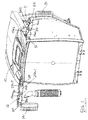
Figure 1 shows a perspective view of the mirror support structure in its extended position; -
Figure 2 shows a plan view of the mirror support structure ofFigure 1 ; -
Figures 3 and4 respectively show plan views of the left and right mirror support structures in their extended positions on a larger scale; -
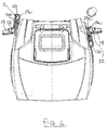
Figure 5 shows a perspective view of the mirror support structure in its retracted position; -
Figure 6 shows a plan view of the mirror support structure ofFigure 5 ; -
Figures 7 and 8 respectively show plan views of the left and right mirror support structures in their retracted positions on a larger scale; -
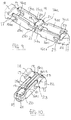
Figures 9 and 10 show perspective views of the left mirror support structure in its extended and retracted positions respectively, and -
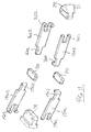
Figure 11 shows an exploded perspective view of the mirror support structure ofFigure 9 . - Referring to the drawings, a
tractor cab 10 is provided with left and right foldingmirror support mechanisms rear view mirrors Figure 1 and the retracted positions shown inFigure 5 . - The left hand mirror support structure 11 (when considering the tractor in the driving direction) comprises first and second pivotally interconnected support arm means 15 and 16 which each comprise pairs of L-shaped arms 15a1,15a2 and 16a1,16a2 respectively. The forked first ends 15b1 and 15b2 of arms 15a1,15a2 are pivotally attached by
pins 17 to asupport bracket 18 which is secured to the cab. The second ends 15c1 and 15c2 of the first support arms 15a1, 15a2 are pivotally connected bypins 19 with connectingplates 20 above and below the arms on which the first ends 16b1 and 16b2 of second support arms 16a1,16a2 are mounted bypins 21. Amirror mount 22 is pivotally mounted on the second ends 16c1 and 16c2 of arms 16a1,16a2 viapins 23. Theleft mirror 13 is pivotally mounted onmount 22. - For ease of construction and economy the L-shaped arms 15a1 and 16a1 are identical and L-shaped arms 15a2 and 16a2 are identical.
- The arms 15a1,15a2 and 16a1,16a2 of the left
hand support mechanism 11 are movable between an extended increased width position shown inFigures 1 to 3 and a retracted reduced width position shown inFigures 5 to 7 . In the extended position the arms 15a1,16a1 and 15a2,16a2 extend in a substantially parallel end to end relationship whereas in the retracted position the arms 15a1,16a1 and 15a2,16a2 extend in a substantially parallel side by side closely nested relationship. - An electric motor (not shown) may be provided to adjust the position of the
mirror mount 22 relative to themounting bracket 18. In such an arrangement the end portion 15c1 of arm 15a1 may be connected via a gear wheel (not shown) with the end 16b1 of the arm 16a1 so that movement of arm 15a1 by the motor also moves arm 16a1. For a firmer drive end potions 15c2 and 16b2 may also be connected by a further gear wheel but this is not essential. If desired a further electric motor can be provided to adjust the position of themirror 13 relative to the mirror mount 22 (if this motor is not provided the mirror is always in the same position unless adjusted manually). - Alternatively these adjustments of the arms and mirror can all be made manually.
- Also other means may be provided to adjust the position of the
mirror 13 and arms e.g. hydraulic or mechanical means. - Similarly the right hand
mirror support mechanism 12 comprises first and second pivotally interconnected support arm means 25 and 26 which each comprise pairs of L-shaped arms 25a1,25a2 and 26a1,26a2 respectively. The forked first ends 25b1 and 25b2 of arms 25a1,25a2 are pivotally attached bypins 27 to asupport bracket 28 which is secured to the cab. The second ends 25c1 and 25c2 of the first support arms 25a1,25a2 are pivotally connected bypins 29 with connectingplates 30 on which the first ends 26b1 and26b2 of second support arms 26a1,26a2 are mounted bypins 31. Amirror mount 32 is pivotally mounted on the second ends 26c1 and 26c2 of arms 26a1,26a2 viapins 33. Theright mirror 14 is pivotally mounted onmount 32. - For ease of construction and economy the L-shaped arms 25a1 and 26a1 are identical and arms 25a2 and 26a2 are identical. Also arms 15a1,16a1,25a2,26a2 are identical and arms 15a2,16a2,25a1,26a1 are identical. Also all the connecting
plates - Again the arms 25a1,25a2 and 26a1,26a2 of the right
hand support mechanism 12 are movable between an extended increased width position shown inFigures 1 ,2 and4 and a retracted reduced width position shown inFigures 5 ,6 and8 . Again in the extended position the arms 25a1,26a1 and 25a2,26a2 extend in a substantially parallel end to end relationship whereas in the retracted position the arms 25a1,26a1 and 25a2,226a2 extend in a substantially parallel side by side relationship. - Again an electric motor (not shown) may be provided to adjust the position of the
mirror mount 32 relative to themounting bracket 28. In such an arrangement the end portion 25c1 of arm 25a1 may be connected via a gear wheel (not shown) with the end 26b1 of the arm 26a1 so that movement of arm 25a1 by the motor also moves arm 26a1. For a firmer drive end potions 25c2 and 26b2 may also be connected by a further gear wheel but this is not essential. If desired a further electric motor can be provided to adjust the position of themirror 14 relative to the mirror mount 32: if this motor is not provided the mirror is always in the same position unless adjusted manually. - Alternatively these adjustments of the arms and mirror can all be made manually or other means such as hydraulic or mechanical means can be used .
- A can be seen from
Figures 5 to 8 , themirror support mechanisms mechanism 11, when in its retracted position, extends to the front of itsmounting bracket 18 to guarantee access to the cab door and themechanism 12 extends to the rear of itsmounting bracket 28 to keep the mirror away from the exhaust. This allows identical arm components to be used for each mechanism. The retracted position is also used as a parking position to give less width. - It is also possible to use only one first arm (e.g. 15a1) and only one second arm (e.g. 16a1) but then it is necessary to use two motors to adjust the position of the mirror mount (e.g. 22) relative to the mounting bracket (e.g. 18). In such an arrangement, because the parallelogram function is missing in the arms, a motor must act on each arm to adjust the position of the mirror mount (22, 32) relative to the mounting bracket (18, 28). Again in this arrangement a third motor can be used to adjust the position of the mirror (13, 14) relative to the mirror mount (22, 32).
- The above folding mirror support mechanism allows the position of the rear view mirrors of an agricultural tractor to be easily adjusted between the different width settings that are necessary to provide a clear rear view around the different trailers, implements or attachments which may be connected to the tractor.
Claims (8)
- A vehicle folding rear view mirror support mechanism comprising first and second pivotally interconnected support arm means, a first end of the first support arm means being pivoted on a mounting bracket for attachment to the vehicle, a second end of the first support arm means being pivotally connected with a first end of the second support arm means, and a mirror mount pivotally connected to a second end of the second support arm means, the first and second arm means being movable between a retracted reduced width position in which the two arm means are in a side by side substantially parallel relationship and an extended increased width position in which the two arm means are substantially end to end and the mirror mount is supported at its maximum distance from the mounting bracket, characterised in that the first and second arm means each comprises a pair of arms, the arms of each pair extending substantially parallel to each other at all times.
- A mechanism according to claim 1 in which each arm means is of an elongated L-shaped configuration to allow the arms means to nest closely in their retracted side by side position.
- A mechanism according to claims 1 and 2 in which the two arm means are pivotally interconnected via connecting plates above and below the arm means.
- A mechanism according to any one of claims 1 to 3 in which a mirror is supported from the mirror mount.
- A mechanism according to claim 1 in which the first pair of arms is connected to the second pair of arms by gear means so that pivoting of the first pair of arms relative to the mounting bracket pivots the second pair of arms relative to the first pair of arms.
- A mechanism according to any one of claims 1 to 5 in which a first motor means acts on the arm means to adjust the position of the mirror mount relative to the mounting bracket.
- A mechanism according to claim 4, in which a second motor means is provided to adjust the position of the mirror relative to the mirror mount.
- A vehicle provided with a pair of mirror support mechanisms according to any one of claims 1 to 7 secured to opposite sides of the vehicle, one mechanism being secured to the vehicle such that in the retracted position the arm means extend to the rear of the mounting bracket and the other mechanism being secured to the vehicle such that in the retracted position the arm means extend to the front of the mounting bracket.
Applications Claiming Priority (1)
| Application Number | Priority Date | Filing Date | Title |
|---|---|---|---|
| GBGB1220764.3A GB201220764D0 (en) | 2012-11-19 | 2012-11-19 | Folding vehicle rear view mirrors |
Publications (2)
| Publication Number | Publication Date |
|---|---|
| EP2733018A1 true EP2733018A1 (en) | 2014-05-21 |
| EP2733018B1 EP2733018B1 (en) | 2015-07-29 |
Family
ID=47521361
Family Applications (1)
| Application Number | Title | Priority Date | Filing Date |
|---|---|---|---|
| EP13185500.9A Active EP2733018B1 (en) | 2012-11-19 | 2013-09-23 | Folding vehicle rear view mirrors |
Country Status (3)
| Country | Link |
|---|---|
| US (1) | US9254788B2 (en) |
| EP (1) | EP2733018B1 (en) |
| GB (1) | GB201220764D0 (en) |
Families Citing this family (4)
| Publication number | Priority date | Publication date | Assignee | Title |
|---|---|---|---|---|
| GB201220764D0 (en) * | 2012-11-19 | 2013-01-02 | Agco Int Gmbh | Folding vehicle rear view mirrors |
| US9919652B2 (en) * | 2016-05-04 | 2018-03-20 | Ford Global Technologies, Llc | Auto-adjusting side-view mirrors |
| JP6847999B2 (en) * | 2019-04-23 | 2021-03-24 | 株式会社ホンダロック | Vehicle door mirrors |
| USD999132S1 (en) * | 2021-07-23 | 2023-09-19 | Deere & Company | Operator cabin mirror assembly for work vehicle |
Citations (9)
| Publication number | Priority date | Publication date | Assignee | Title |
|---|---|---|---|---|
| US3031929A (en) * | 1959-12-07 | 1962-05-01 | Lansing Company | Truck mirror construction |
| GB1339123A (en) * | 1969-12-19 | 1973-11-28 | Magnatex Ltd | Vehicle rear-view mirror mountings |
| DE3938961A1 (en) * | 1989-11-24 | 1991-05-29 | Kloeckner Humboldt Deutz Ag | Telescoping outside rear-view mirror for farm tractors - uses rod driven via crown gears by motor to allow remote positioning of mirror |
| JPH03113246U (en) * | 1990-03-08 | 1991-11-19 | ||
| JPH08282379A (en) * | 1995-04-14 | 1996-10-29 | Sadako Mizukami | Rear safety confirming device for lorry |
| US6325518B1 (en) * | 1999-03-12 | 2001-12-04 | Donnelly Corporation | Extendable exterior rearview mirror assembly |
| US20030117729A1 (en) * | 2001-05-02 | 2003-06-26 | Foote Keith D. | Coordinated pivoting and extending vehicle mirror |
| US20080179485A1 (en) * | 2007-01-30 | 2008-07-31 | Kun-Shan Yang | Vehicular side mirror |
| EP2489552A2 (en) * | 2011-02-18 | 2012-08-22 | Turhan Yilmaz | Rear view mirror for a motor vehicle |
Family Cites Families (5)
| Publication number | Priority date | Publication date | Assignee | Title |
|---|---|---|---|---|
| US3339876A (en) * | 1964-06-29 | 1967-09-05 | J W Speaker Corp | Side mount rear view truck mirror |
| GB9720912D0 (en) * | 1997-10-03 | 1997-12-03 | Britax Rainsfords Pty Ltd | Vehicle exterior mirror |
| WO2001059734A1 (en) * | 2000-02-11 | 2001-08-16 | Britax Vision Systems (North America) Inc. | Exterior mirror |
| US20050213231A1 (en) * | 2004-03-29 | 2005-09-29 | Harrison Charles E Iii | Backing mirror |
| GB201220764D0 (en) * | 2012-11-19 | 2013-01-02 | Agco Int Gmbh | Folding vehicle rear view mirrors |
-
2012
- 2012-11-19 GB GBGB1220764.3A patent/GB201220764D0/en not_active Ceased
-
2013
- 2013-09-23 EP EP13185500.9A patent/EP2733018B1/en active Active
- 2013-11-19 US US14/084,018 patent/US9254788B2/en not_active Expired - Fee Related
Patent Citations (9)
| Publication number | Priority date | Publication date | Assignee | Title |
|---|---|---|---|---|
| US3031929A (en) * | 1959-12-07 | 1962-05-01 | Lansing Company | Truck mirror construction |
| GB1339123A (en) * | 1969-12-19 | 1973-11-28 | Magnatex Ltd | Vehicle rear-view mirror mountings |
| DE3938961A1 (en) * | 1989-11-24 | 1991-05-29 | Kloeckner Humboldt Deutz Ag | Telescoping outside rear-view mirror for farm tractors - uses rod driven via crown gears by motor to allow remote positioning of mirror |
| JPH03113246U (en) * | 1990-03-08 | 1991-11-19 | ||
| JPH08282379A (en) * | 1995-04-14 | 1996-10-29 | Sadako Mizukami | Rear safety confirming device for lorry |
| US6325518B1 (en) * | 1999-03-12 | 2001-12-04 | Donnelly Corporation | Extendable exterior rearview mirror assembly |
| US20030117729A1 (en) * | 2001-05-02 | 2003-06-26 | Foote Keith D. | Coordinated pivoting and extending vehicle mirror |
| US20080179485A1 (en) * | 2007-01-30 | 2008-07-31 | Kun-Shan Yang | Vehicular side mirror |
| EP2489552A2 (en) * | 2011-02-18 | 2012-08-22 | Turhan Yilmaz | Rear view mirror for a motor vehicle |
Also Published As
| Publication number | Publication date |
|---|---|
| US20140139938A1 (en) | 2014-05-22 |
| US9254788B2 (en) | 2016-02-09 |
| EP2733018B1 (en) | 2015-07-29 |
| GB201220764D0 (en) | 2013-01-02 |
Similar Documents
| Publication | Publication Date | Title |
|---|---|---|
| EP2733018A1 (en) | Folding vehicle rear view mirrors | |
| EP2203606B1 (en) | Extensible snowplough blade | |
| US10370821B2 (en) | Work vehicle | |
| US8789646B2 (en) | Steering apparatus of for a tractor | |
| US20170079191A1 (en) | Laterally moveable hitch assembly for a tractor | |
| BR102016006351B1 (en) | agricultural harvester | |
| CN103843483A (en) | Folding earth-working tool attachment of agricultural | |
| JP2010520101A5 (en) | ||
| EP2512212B1 (en) | Agricultural device | |
| US20080276499A1 (en) | Blade attachment device | |
| US20150027097A1 (en) | Connection device for an attachment of a self-propelled work machine | |
| CN114174117A (en) | Long-range scalable mirror | |
| EP2894075A2 (en) | Suspension for baby pushchairs | |
| EP3571908A3 (en) | Folding hitch | |
| CN110387917B (en) | Motor grader with center-mounted turner system | |
| US11439066B2 (en) | Length-variable and pitch-adjustable wheelbase combine | |
| US6955229B1 (en) | Implement pitch-yaw system | |
| IT202100000845A1 (en) | FRONT LOWER LINK SYSTEM FOR SUPER STEERING AGRICULTURAL VEHICLES AND SUPER STEER AGRICULTURAL VEHICLES INCLUDING FRONT LOWER LINK SYSTEM | |
| EP2508390A1 (en) | System in particular for recovering broken-down vehicles | |
| AU2016257620B2 (en) | Cantilever for a utility vehicle | |
| EP2048289A2 (en) | Utility vehicle with a stop element on a front loader | |
| US10668960B1 (en) | Plow conversion kit | |
| JP5955066B2 (en) | Agricultural machine | |
| CN109228968A (en) | The servo-actuated wheel loader seat of work operative system | |
| EP3516939A1 (en) | Towed agricultural implement |
Legal Events
| Date | Code | Title | Description |
|---|---|---|---|
| PUAI | Public reference made under article 153(3) epc to a published international application that has entered the european phase |
Free format text: ORIGINAL CODE: 0009012 |
|
| 17P | Request for examination filed |
Effective date: 20130923 |
|
| AK | Designated contracting states |
Kind code of ref document: A1 Designated state(s): AL AT BE BG CH CY CZ DE DK EE ES FI FR GB GR HR HU IE IS IT LI LT LU LV MC MK MT NL NO PL PT RO RS SE SI SK SM TR |
|
| AX | Request for extension of the european patent |
Extension state: BA ME |
|
| R17P | Request for examination filed (corrected) |
Effective date: 20141121 |
|
| RBV | Designated contracting states (corrected) |
Designated state(s): AL AT BE BG CH CY CZ DE DK EE ES FI FR GB GR HR HU IE IS IT LI LT LU LV MC MK MT NL NO PL PT RO RS SE SI SK SM TR |
|
| GRAP | Despatch of communication of intention to grant a patent |
Free format text: ORIGINAL CODE: EPIDOSNIGR1 |
|
| INTG | Intention to grant announced |
Effective date: 20150331 |
|
| GRAS | Grant fee paid |
Free format text: ORIGINAL CODE: EPIDOSNIGR3 |
|
| GRAA | (expected) grant |
Free format text: ORIGINAL CODE: 0009210 |
|
| AK | Designated contracting states |
Kind code of ref document: B1 Designated state(s): AL AT BE BG CH CY CZ DE DK EE ES FI FR GB GR HR HU IE IS IT LI LT LU LV MC MK MT NL NO PL PT RO RS SE SI SK SM TR |
|
| REG | Reference to a national code |
Ref country code: GB Ref legal event code: FG4D |
|
| REG | Reference to a national code |
Ref country code: CH Ref legal event code: EP |
|
| REG | Reference to a national code |
Ref country code: AT Ref legal event code: REF Ref document number: 738983 Country of ref document: AT Kind code of ref document: T Effective date: 20150815 |
|
| REG | Reference to a national code |
Ref country code: IE Ref legal event code: FG4D |
|
| REG | Reference to a national code |
Ref country code: DE Ref legal event code: R096 Ref document number: 602013002434 Country of ref document: DE |
|
| REG | Reference to a national code |
Ref country code: FR Ref legal event code: PLFP Year of fee payment: 3 |
|
| REG | Reference to a national code |
Ref country code: AT Ref legal event code: MK05 Ref document number: 738983 Country of ref document: AT Kind code of ref document: T Effective date: 20150729 |
|
| REG | Reference to a national code |
Ref country code: LT Ref legal event code: MG4D |
|
| REG | Reference to a national code |
Ref country code: NL Ref legal event code: MP Effective date: 20150729 |
|
| PG25 | Lapsed in a contracting state [announced via postgrant information from national office to epo] |
Ref country code: FI Free format text: LAPSE BECAUSE OF FAILURE TO SUBMIT A TRANSLATION OF THE DESCRIPTION OR TO PAY THE FEE WITHIN THE PRESCRIBED TIME-LIMIT Effective date: 20150729 Ref country code: GR Free format text: LAPSE BECAUSE OF FAILURE TO SUBMIT A TRANSLATION OF THE DESCRIPTION OR TO PAY THE FEE WITHIN THE PRESCRIBED TIME-LIMIT Effective date: 20151030 Ref country code: LV Free format text: LAPSE BECAUSE OF FAILURE TO SUBMIT A TRANSLATION OF THE DESCRIPTION OR TO PAY THE FEE WITHIN THE PRESCRIBED TIME-LIMIT Effective date: 20150729 Ref country code: LT Free format text: LAPSE BECAUSE OF FAILURE TO SUBMIT A TRANSLATION OF THE DESCRIPTION OR TO PAY THE FEE WITHIN THE PRESCRIBED TIME-LIMIT Effective date: 20150729 Ref country code: NO Free format text: LAPSE BECAUSE OF FAILURE TO SUBMIT A TRANSLATION OF THE DESCRIPTION OR TO PAY THE FEE WITHIN THE PRESCRIBED TIME-LIMIT Effective date: 20151029 |
|
| PG25 | Lapsed in a contracting state [announced via postgrant information from national office to epo] |
Ref country code: AT Free format text: LAPSE BECAUSE OF FAILURE TO SUBMIT A TRANSLATION OF THE DESCRIPTION OR TO PAY THE FEE WITHIN THE PRESCRIBED TIME-LIMIT Effective date: 20150729 Ref country code: PT Free format text: LAPSE BECAUSE OF FAILURE TO SUBMIT A TRANSLATION OF THE DESCRIPTION OR TO PAY THE FEE WITHIN THE PRESCRIBED TIME-LIMIT Effective date: 20151130 Ref country code: ES Free format text: LAPSE BECAUSE OF FAILURE TO SUBMIT A TRANSLATION OF THE DESCRIPTION OR TO PAY THE FEE WITHIN THE PRESCRIBED TIME-LIMIT Effective date: 20150729 Ref country code: IS Free format text: LAPSE BECAUSE OF FAILURE TO SUBMIT A TRANSLATION OF THE DESCRIPTION OR TO PAY THE FEE WITHIN THE PRESCRIBED TIME-LIMIT Effective date: 20151129 Ref country code: HR Free format text: LAPSE BECAUSE OF FAILURE TO SUBMIT A TRANSLATION OF THE DESCRIPTION OR TO PAY THE FEE WITHIN THE PRESCRIBED TIME-LIMIT Effective date: 20150729 Ref country code: SE Free format text: LAPSE BECAUSE OF FAILURE TO SUBMIT A TRANSLATION OF THE DESCRIPTION OR TO PAY THE FEE WITHIN THE PRESCRIBED TIME-LIMIT Effective date: 20150729 Ref country code: PL Free format text: LAPSE BECAUSE OF FAILURE TO SUBMIT A TRANSLATION OF THE DESCRIPTION OR TO PAY THE FEE WITHIN THE PRESCRIBED TIME-LIMIT Effective date: 20150729 Ref country code: RS Free format text: LAPSE BECAUSE OF FAILURE TO SUBMIT A TRANSLATION OF THE DESCRIPTION OR TO PAY THE FEE WITHIN THE PRESCRIBED TIME-LIMIT Effective date: 20150729 |
|
| PG25 | Lapsed in a contracting state [announced via postgrant information from national office to epo] |
Ref country code: NL Free format text: LAPSE BECAUSE OF FAILURE TO SUBMIT A TRANSLATION OF THE DESCRIPTION OR TO PAY THE FEE WITHIN THE PRESCRIBED TIME-LIMIT Effective date: 20150729 |
|
| PG25 | Lapsed in a contracting state [announced via postgrant information from national office to epo] |
Ref country code: EE Free format text: LAPSE BECAUSE OF FAILURE TO SUBMIT A TRANSLATION OF THE DESCRIPTION OR TO PAY THE FEE WITHIN THE PRESCRIBED TIME-LIMIT Effective date: 20150729 Ref country code: MC Free format text: LAPSE BECAUSE OF FAILURE TO SUBMIT A TRANSLATION OF THE DESCRIPTION OR TO PAY THE FEE WITHIN THE PRESCRIBED TIME-LIMIT Effective date: 20150729 Ref country code: LU Free format text: LAPSE BECAUSE OF FAILURE TO SUBMIT A TRANSLATION OF THE DESCRIPTION OR TO PAY THE FEE WITHIN THE PRESCRIBED TIME-LIMIT Effective date: 20150923 Ref country code: DK Free format text: LAPSE BECAUSE OF FAILURE TO SUBMIT A TRANSLATION OF THE DESCRIPTION OR TO PAY THE FEE WITHIN THE PRESCRIBED TIME-LIMIT Effective date: 20150729 Ref country code: SK Free format text: LAPSE BECAUSE OF FAILURE TO SUBMIT A TRANSLATION OF THE DESCRIPTION OR TO PAY THE FEE WITHIN THE PRESCRIBED TIME-LIMIT Effective date: 20150729 Ref country code: CZ Free format text: LAPSE BECAUSE OF FAILURE TO SUBMIT A TRANSLATION OF THE DESCRIPTION OR TO PAY THE FEE WITHIN THE PRESCRIBED TIME-LIMIT Effective date: 20150729 |
|
| REG | Reference to a national code |
Ref country code: DE Ref legal event code: R097 Ref document number: 602013002434 Country of ref document: DE |
|
| PG25 | Lapsed in a contracting state [announced via postgrant information from national office to epo] |
Ref country code: RO Free format text: LAPSE BECAUSE OF FAILURE TO SUBMIT A TRANSLATION OF THE DESCRIPTION OR TO PAY THE FEE WITHIN THE PRESCRIBED TIME-LIMIT Effective date: 20150729 |
|
| PLBE | No opposition filed within time limit |
Free format text: ORIGINAL CODE: 0009261 |
|
| STAA | Information on the status of an ep patent application or granted ep patent |
Free format text: STATUS: NO OPPOSITION FILED WITHIN TIME LIMIT |
|
| REG | Reference to a national code |
Ref country code: IE Ref legal event code: MM4A |
|
| 26N | No opposition filed |
Effective date: 20160502 |
|
| PG25 | Lapsed in a contracting state [announced via postgrant information from national office to epo] |
Ref country code: IE Free format text: LAPSE BECAUSE OF NON-PAYMENT OF DUE FEES Effective date: 20150923 |
|
| PG25 | Lapsed in a contracting state [announced via postgrant information from national office to epo] |
Ref country code: SI Free format text: LAPSE BECAUSE OF FAILURE TO SUBMIT A TRANSLATION OF THE DESCRIPTION OR TO PAY THE FEE WITHIN THE PRESCRIBED TIME-LIMIT Effective date: 20150729 |
|
| REG | Reference to a national code |
Ref country code: FR Ref legal event code: PLFP Year of fee payment: 4 |
|
| PG25 | Lapsed in a contracting state [announced via postgrant information from national office to epo] |
Ref country code: BE Free format text: LAPSE BECAUSE OF FAILURE TO SUBMIT A TRANSLATION OF THE DESCRIPTION OR TO PAY THE FEE WITHIN THE PRESCRIBED TIME-LIMIT Effective date: 20150729 |
|
| PG25 | Lapsed in a contracting state [announced via postgrant information from national office to epo] |
Ref country code: MT Free format text: LAPSE BECAUSE OF FAILURE TO SUBMIT A TRANSLATION OF THE DESCRIPTION OR TO PAY THE FEE WITHIN THE PRESCRIBED TIME-LIMIT Effective date: 20150729 |
|
| REG | Reference to a national code |
Ref country code: CH Ref legal event code: PL |
|
| PG25 | Lapsed in a contracting state [announced via postgrant information from national office to epo] |
Ref country code: HU Free format text: LAPSE BECAUSE OF FAILURE TO SUBMIT A TRANSLATION OF THE DESCRIPTION OR TO PAY THE FEE WITHIN THE PRESCRIBED TIME-LIMIT; INVALID AB INITIO Effective date: 20130923 Ref country code: BG Free format text: LAPSE BECAUSE OF FAILURE TO SUBMIT A TRANSLATION OF THE DESCRIPTION OR TO PAY THE FEE WITHIN THE PRESCRIBED TIME-LIMIT Effective date: 20150729 |
|
| PG25 | Lapsed in a contracting state [announced via postgrant information from national office to epo] |
Ref country code: CY Free format text: LAPSE BECAUSE OF FAILURE TO SUBMIT A TRANSLATION OF THE DESCRIPTION OR TO PAY THE FEE WITHIN THE PRESCRIBED TIME-LIMIT Effective date: 20150729 |
|
| PG25 | Lapsed in a contracting state [announced via postgrant information from national office to epo] |
Ref country code: LI Free format text: LAPSE BECAUSE OF NON-PAYMENT OF DUE FEES Effective date: 20160930 Ref country code: CH Free format text: LAPSE BECAUSE OF NON-PAYMENT OF DUE FEES Effective date: 20160930 |
|
| REG | Reference to a national code |
Ref country code: FR Ref legal event code: PLFP Year of fee payment: 5 |
|
| PG25 | Lapsed in a contracting state [announced via postgrant information from national office to epo] |
Ref country code: SM Free format text: LAPSE BECAUSE OF FAILURE TO SUBMIT A TRANSLATION OF THE DESCRIPTION OR TO PAY THE FEE WITHIN THE PRESCRIBED TIME-LIMIT Effective date: 20150729 |
|
| PG25 | Lapsed in a contracting state [announced via postgrant information from national office to epo] |
Ref country code: MK Free format text: LAPSE BECAUSE OF FAILURE TO SUBMIT A TRANSLATION OF THE DESCRIPTION OR TO PAY THE FEE WITHIN THE PRESCRIBED TIME-LIMIT Effective date: 20150729 Ref country code: TR Free format text: LAPSE BECAUSE OF FAILURE TO SUBMIT A TRANSLATION OF THE DESCRIPTION OR TO PAY THE FEE WITHIN THE PRESCRIBED TIME-LIMIT Effective date: 20150729 |
|
| REG | Reference to a national code |
Ref country code: FR Ref legal event code: PLFP Year of fee payment: 6 |
|
| PG25 | Lapsed in a contracting state [announced via postgrant information from national office to epo] |
Ref country code: AL Free format text: LAPSE BECAUSE OF FAILURE TO SUBMIT A TRANSLATION OF THE DESCRIPTION OR TO PAY THE FEE WITHIN THE PRESCRIBED TIME-LIMIT Effective date: 20150729 |
|
| PGFP | Annual fee paid to national office [announced via postgrant information from national office to epo] |
Ref country code: IT Payment date: 20180921 Year of fee payment: 6 |
|
| PGFP | Annual fee paid to national office [announced via postgrant information from national office to epo] |
Ref country code: GB Payment date: 20180919 Year of fee payment: 6 |
|
| PG25 | Lapsed in a contracting state [announced via postgrant information from national office to epo] |
Ref country code: IT Free format text: LAPSE BECAUSE OF NON-PAYMENT OF DUE FEES Effective date: 20190923 |
|
| GBPC | Gb: european patent ceased through non-payment of renewal fee |
Effective date: 20190923 |
|
| PG25 | Lapsed in a contracting state [announced via postgrant information from national office to epo] |
Ref country code: GB Free format text: LAPSE BECAUSE OF NON-PAYMENT OF DUE FEES Effective date: 20190923 |
|
| P01 | Opt-out of the competence of the unified patent court (upc) registered |
Effective date: 20230518 |
|
| PGFP | Annual fee paid to national office [announced via postgrant information from national office to epo] |
Ref country code: FR Payment date: 20230928 Year of fee payment: 11 Ref country code: DE Payment date: 20230920 Year of fee payment: 11 |