EP2747047A1 - Smoke alarm with battery charge level indicator - Google Patents
Smoke alarm with battery charge level indicator Download PDFInfo
- Publication number
- EP2747047A1 EP2747047A1 EP20130306697 EP13306697A EP2747047A1 EP 2747047 A1 EP2747047 A1 EP 2747047A1 EP 20130306697 EP20130306697 EP 20130306697 EP 13306697 A EP13306697 A EP 13306697A EP 2747047 A1 EP2747047 A1 EP 2747047A1
- Authority
- EP
- European Patent Office
- Prior art keywords
- display
- smoke detector
- display element
- battery
- states
- Prior art date
- Legal status (The legal status is an assumption and is not a legal conclusion. Google has not performed a legal analysis and makes no representation as to the accuracy of the status listed.)
- Withdrawn
Links
Images


Classifications
-
- G—PHYSICS
- G08—SIGNALLING
- G08B—SIGNALLING OR CALLING SYSTEMS; ORDER TELEGRAPHS; ALARM SYSTEMS
- G08B5/00—Visible signalling systems, e.g. personal calling systems, remote indication of seats occupied
- G08B5/22—Visible signalling systems, e.g. personal calling systems, remote indication of seats occupied using electric transmission; using electromagnetic transmission
-
- G—PHYSICS
- G02—OPTICS
- G02F—OPTICAL DEVICES OR ARRANGEMENTS FOR THE CONTROL OF LIGHT BY MODIFICATION OF THE OPTICAL PROPERTIES OF THE MEDIA OF THE ELEMENTS INVOLVED THEREIN; NON-LINEAR OPTICS; FREQUENCY-CHANGING OF LIGHT; OPTICAL LOGIC ELEMENTS; OPTICAL ANALOGUE/DIGITAL CONVERTERS
- G02F1/00—Devices or arrangements for the control of the intensity, colour, phase, polarisation or direction of light arriving from an independent light source, e.g. switching, gating or modulating; Non-linear optics
- G02F1/01—Devices or arrangements for the control of the intensity, colour, phase, polarisation or direction of light arriving from an independent light source, e.g. switching, gating or modulating; Non-linear optics for the control of the intensity, phase, polarisation or colour
- G02F1/13—Devices or arrangements for the control of the intensity, colour, phase, polarisation or direction of light arriving from an independent light source, e.g. switching, gating or modulating; Non-linear optics for the control of the intensity, phase, polarisation or colour based on liquid crystals, e.g. single liquid crystal display cells
- G02F1/137—Devices or arrangements for the control of the intensity, colour, phase, polarisation or direction of light arriving from an independent light source, e.g. switching, gating or modulating; Non-linear optics for the control of the intensity, phase, polarisation or colour based on liquid crystals, e.g. single liquid crystal display cells characterised by the electro-optical or magneto-optical effect, e.g. field-induced phase transition, orientation effect, guest-host interaction or dynamic scattering
- G02F1/139—Devices or arrangements for the control of the intensity, colour, phase, polarisation or direction of light arriving from an independent light source, e.g. switching, gating or modulating; Non-linear optics for the control of the intensity, phase, polarisation or colour based on liquid crystals, e.g. single liquid crystal display cells characterised by the electro-optical or magneto-optical effect, e.g. field-induced phase transition, orientation effect, guest-host interaction or dynamic scattering based on orientation effects in which the liquid crystal remains transparent
- G02F1/1391—Bistable or multi-stable liquid crystal cells
-
- G—PHYSICS
- G08—SIGNALLING
- G08B—SIGNALLING OR CALLING SYSTEMS; ORDER TELEGRAPHS; ALARM SYSTEMS
- G08B17/00—Fire alarms; Alarms responsive to explosion
-
- G—PHYSICS
- G08—SIGNALLING
- G08B—SIGNALLING OR CALLING SYSTEMS; ORDER TELEGRAPHS; ALARM SYSTEMS
- G08B29/00—Checking or monitoring of signalling or alarm systems; Prevention or correction of operating errors, e.g. preventing unauthorised operation
- G08B29/18—Prevention or correction of operating errors
- G08B29/181—Prevention or correction of operating errors due to failing power supply
-
- G—PHYSICS
- G08—SIGNALLING
- G08B—SIGNALLING OR CALLING SYSTEMS; ORDER TELEGRAPHS; ALARM SYSTEMS
- G08B17/00—Fire alarms; Alarms responsive to explosion
- G08B17/10—Actuation by presence of smoke or gases, e.g. automatic alarm devices for analysing flowing fluid materials by the use of optical means
- G08B17/11—Actuation by presence of smoke or gases, e.g. automatic alarm devices for analysing flowing fluid materials by the use of optical means using an ionisation chamber for detecting smoke or gas
- G08B17/113—Constructional details
Definitions
- the invention relates to a battery-operated smoke detector comprising a monitoring device for monitoring a battery voltage and a display element for displaying a battery voltage state.
- Smoke detectors with a display element for indicating a battery voltage state are basically known, the display serving to signal an insufficient battery voltage.
- An acoustic indication of an undervoltage over an extended period of time can be perceived as disturbing.
- a perception is not possible.
- such acoustic displays as well as optical display elements burden the battery of the smoke detector up to a failure of the display, so that the battery undervoltage can not be signaled.
- optical displays such as flashing LEDs
- the battery of the smoke detector is additionally charged during operation.
- the invention has for its object to provide a battery-operated smoke detector, which has increased security against undervoltages reduced energy consumption.
- a smoke detector is provided with the features of claim 1.
- the battery-operated smoke detector comprises a monitoring device for monitoring a battery voltage and a display element for displaying a battery voltage state, wherein the display element has at least two without a power supply maintained display states. Since displaying the display states does not require a power supply, a sufficient or insufficient battery voltage state can be permanently displayed without loading the battery of the smoke detector. By the invention it is possible to switch the display to inform the user of the smoke detector about a too low battery voltage, even if immediately thereafter the battery voltage for the power supply of the smoke detector and also for a permanent display is no longer sufficient. Thus, when viewing the display element of the smoke detector for the user clearly and even after a long absence always recognizable whether the battery of the smoke detector must be replaced.
- the display element comprises a bistable liquid crystal display, eg a cholesteric liquid crystal display or a ferroelectric liquid crystal display.
- the bistable liquid crystal display consumes power only to change the display state.
- the bistable liquid crystal display immediately before the complete discharge of the battery can switch the display state and then maintain the display state as long as desired despite a discharged battery.
- Bistable liquid crystal displays also have a high resolution, whereby a detailed display element can be realized with low power consumption.
- a structurally particularly simple and cost-effective display element can be realized if the display element comprises an electromagnetic-mechanical device.
- the switching between the display states is effected via the electromagnetic-mechanical device, such as e.g. a tilting or rotating device.
- the electromagnetic-mechanical device such as e.g. a tilting or rotating device.
- Such devices are characterized by the fact that they are particularly reliable, which is particularly important in a smoke detector.
- the electromagnetic-mechanical device comprises a flip-dot component, whereby a variety of design possibilities of the display states is made possible.
- the different display states can be painted, coated or labeled in different colors.
- the display states of the display element may each have a different light transmission, which is possible for example by the use of an electrochromic glass, whereby at the same time a pleasant aesthetics and easily distinguishable display states can be realized.
- the display states of the display element each have a different reflectivity.
- a difference between the reflectivities of the display states may be particularly helpful when the smoke detector needs to be mounted at a relatively large distance from the user, e.g. on a high ceiling.
- the display states of the display element alternatively or additionally each have a different color.
- a color difference proves to be advantageous in that the difference between the display conditions can be made particularly conspicuous. This conspicuousness makes it easier to detect a change in the battery voltage. For example, in a display state where the battery does not need to be replaced, the display state may be white. If a housing of the smoke detector is also white, on the other hand, a display state in red when the battery needs to be replaced is visually very easily recognizable.
- the display state comprises a symbol, thereby enabling a compact and easily recognizable presentation of information.
- At least one display state of the display element additionally or alternatively comprise a character.
- the display state may include a brief instruction about a necessary action of the user.
- the display element when the display states of the display element are generated by constructive and destructive interference, the display element may be configured as an interferometric modulator display, thereby enabling rapid switching between detailed display states.
- the display element may additionally include an acoustic message on the occasion of switching between display states, which makes the user aware of the switching in the short term. Because the audible message no longer works as the sole ad must, it can be kept short to avoid disturbing effect as possible.
- the smoke detector according to the invention may be designed according to a further advantageous embodiment as a disposable device. In such a device, no battery change is possible, but the complete smoke detector must be replaced.
- the display device according to the invention ensures that a reliable and permanent display is available even when the battery is completely empty, which signals a required change of the smoke detector.
- Fig. 1 shows purely schematically a smoke detector 10 for detecting smoke, which can be mounted on a ceiling or wall space.
- the smoke detector 10 includes in a known manner sensor means for detecting smoke, which are not shown here for reasons of clarity.
- a battery 12 is used to power the smoke detector 10.
- a monitoring device 14 monitors a battery voltage of the battery 12.
- the monitoring device 14 controls a display element 16, which indicates the user of the smoke detector, the state of too low a battery voltage.
- the display element 16 comprises at least two display states indicating sufficient and insufficient battery voltage.
- a first display state 20a is displayed ( FIGS. 2A to 2E ).
- the display state 20a informs the user that the battery voltage of the battery 12 is sufficient for the operation of the smoke detector 10.
- the battery 12 After a certain time, the battery 12 is almost discharged. As in Fig. 1 shown, the monitoring device 14 and the battery 12 are in communication with each other, so that the monitoring device 14 detects a too low battery voltage. Subsequently, the monitoring device 14 controls the display element 16, whereby a second display state 20 b of the display element 16 is switched. As compared with the first display state 20a, the display state 20b shows that the battery 12 needs to be changed by the user.
- the maintenance of the display states 20a, 20b does not require electrical energy, ie only a voltage supply is needed to switch between the display states 20a, 20b.
- both display states 20a, 20b can be realized in a particularly energy-efficient manner.
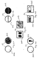
- FIGS. 2A to 2E For example, embodiments of display states 20a, 20b, 20c, 20d according to the invention are shown.
- Fig. 2A shows a simple embodiment of two display states 20a, 20b, wherein in a first display state 20a, a circular colorless surface is shown. It is understood that the shape of the display state 20a is purely illustrative in FIG Fig. 2A represented and can be configured as desired.
- the display state 20a informs the user that a sufficient battery voltage is present. When the battery 12 is almost discharged, the monitor 14 switches the display element 16 to the display state 20b, indicating that the battery 12 needs to be changed. Since the maintenance of the display state 20b consumes no power, it can be displayed indefinitely until the user perceives it and the battery 12 changes. It is understood that the display states 20a, 20b may have a reverse meaning, ie, the display state 20a is displayed when necessary battery replacement and the display state 20b is displayed at a sufficiently charged battery 12.
- FIG. 2A shown embodiment of the display states 20a, 20b can be realized for example via a bistable liquid crystal display.
- the liquid crystals of the display element 15 for the display state 20a are aligned in one direction.
- the liquid crystals are directed in a different orientation, which orientation they maintain without power supply until the next switching.
- the difference between the display states 20a, 20b can also be realized by other techniques, eg by electrochromism, an interferometric modulator display or by different reflectivities of the display states 20a, 20b.
- the display states 20a, 20b can also be realized by a display element 16 with an electromagnetic-mechanical device, for example a turning or tilting device, as in FIG Fig. 2B is shown.
- the first display state 20a comprises two semicircular plates which are held by the device of the display element 16 in a first position without power supply.
- the plates are tilted by the device in a second position. In the second position, the display state 20b is displayed, which includes two semi-circular plates of a different color.
- Fig. 12 shows another embodiment of the display states 20a, 20b in which a square display element 16 in the first display state 20a displays characters which form the word "OK". In this case, the user understands that the battery 12 is "in order", ie the battery 12 does not have to be changed.
- the second display state 20b indicates a black square, thereby informing the user of the necessary battery replacement.
- At least one display state may include a symbol. In this case, nothing is displayed in the first display state 20a, and a symbol for changing the battery is displayed in the second display state 20b.
- Fig. 2E shows an embodiment of two display states 20c, 20d, with which detailed information is displayed.
- the first display state 20c shows a first state of the battery voltage
- the second display state 20d shows a second state of the battery voltage, in which the battery 12 is compared with the first display state 20c is slightly more unloaded.
- the embodiment may include other display states not shown.
- a bistable liquid crystal display is suitable because of its high resolution because the display states 20c, 20d indicate more detailed information than the display states 20a, 20b.
- FIGS. 2A to 2E shown display states 20a, 20b, 20c, 20d can also be combined.
- FIGS. 3A and 3B show two different embodiments of a smoke detector 10 with a housing 30.
- the display element 16 must be arranged on the housing 30 of the smoke detector 10 so that the user can see the display element 16 after mounting the smoke detector 10.
- the display element 16 is disposed on a side housing surface 31.
- the display element 16 is disposed on a lower side of the housing 32, whereby the display element 16 is particularly well recognized in the assembled state. It is understood that the display element 16 arranged laterally can be circular and the display element 16 arranged on the lower housing side 32 can be made square.
Abstract
Description
Die Erfindung betrifft einen batteriebetriebenen Rauchmelder umfassend eine Überwachungseinrichtung zur Überwachung einer Batteriespannung und ein Anzeigeelement zum Anzeigen eines Batteriespannungszustands.The invention relates to a battery-operated smoke detector comprising a monitoring device for monitoring a battery voltage and a display element for displaying a battery voltage state.
Rauchmelder mit einem Anzeigeelement zum Anzeigen eines Batteriespannungszustands sind grundsätzlich bekannt, wobei die Anzeige dazu dient, eine nicht ausreichende Batteriespannung zu signalisieren. Eine über einen längeren Zeitraum erfolgende akustische Anzeige einer Unterspannung kann als störend empfunden werden. Wenn ferner das Signalisieren ausschließlich in Abwesenheit des Benutzers erfolgt, ist eine Wahrnehmung nicht möglich. Weiterhin belasten derartige akustische Anzeigen wie auch optische Anzeigeelemente die Batterie des Rauchmelders bis hin zu einem Ausfall der Anzeige, so dass die Batterieunterspannung nicht mehr signalisiert werden kann. Bei optischen Anzeigen, wie beispielsweise blinkenden LEDs, kommt hinzu, dass die Batterie des Rauchmelders auch während des Betriebs zusätzlich belastet wird.Smoke detectors with a display element for indicating a battery voltage state are basically known, the display serving to signal an insufficient battery voltage. An acoustic indication of an undervoltage over an extended period of time can be perceived as disturbing. Furthermore, if the signaling takes place exclusively in the absence of the user, a perception is not possible. Furthermore, such acoustic displays as well as optical display elements burden the battery of the smoke detector up to a failure of the display, so that the battery undervoltage can not be signaled. With optical displays, such as flashing LEDs, in addition, the battery of the smoke detector is additionally charged during operation.
Der Erfindung liegt die Aufgabe zugrunde, einen batteriebetriebenen Rauchmelder zu schaffen, der bei erhöhter Sicherheit gegen Unterspannung einen reduzierten Energieverbrauch aufweist.The invention has for its object to provide a battery-operated smoke detector, which has increased security against undervoltages reduced energy consumption.
Zur Lösung der Aufgabe ist ein Rauchmelder mit den Merkmalen des Anspruchs 1 vorgesehen.To solve the problem, a smoke detector is provided with the features of claim 1.
Der erfindungsgemäße batteriebetriebene Rauchmelder weist eine Überwachungseinrichtung zur Überwachung einer Batteriespannung und ein Anzeigeelement zum Anzeigen eines Batteriespannungszustands auf, wobei das Anzeigeelement mindestens zwei sich ohne eine Spannungsversorgung aufrechterhaltende Anzeigezustände besitzt. Da das Anzeigen der Anzeigezustände keine Spannungsversorgung benötigt, kann ein ausreichender oder nicht ausreichender Batteriespannungszustand dauerhaft angezeigt werden ohne die Batterie des Rauchmelders zu belasten. Durch die Erfindung ist es möglich, die Anzeige umzuschalten, um den Benutzer des Rauchmelders über eine zu niedrige Batteriespannung zu informieren, auch wenn unmittelbar danach die Batteriespannung für die Spannungsversorgung des Rauchmelders und auch für eine dauerhafte Anzeige nicht mehr ausreicht. Somit ist beim Betrachten des Anzeigeelements des Rauchmelders für den Benutzer eindeutig und auch nach längerer Abwesenheit immer erkennbar, ob die Batterie des Rauchmelders ausgetauscht werden muss.The battery-operated smoke detector according to the invention comprises a monitoring device for monitoring a battery voltage and a display element for displaying a battery voltage state, wherein the display element has at least two without a power supply maintained display states. Since displaying the display states does not require a power supply, a sufficient or insufficient battery voltage state can be permanently displayed without loading the battery of the smoke detector. By the invention it is possible to switch the display to inform the user of the smoke detector about a too low battery voltage, even if immediately thereafter the battery voltage for the power supply of the smoke detector and also for a permanent display is no longer sufficient. Thus, when viewing the display element of the smoke detector for the user clearly and even after a long absence always recognizable whether the battery of the smoke detector must be replaced.
Vorteilhafte Ausbildungen der Erfindung sind den Unteransprüchen, der Beschreibung und der Zeichnung zu entnehmen.Advantageous embodiments of the invention are described in the dependent claims, the description and the drawings.
Gemäß einer vorteilhaften Ausführungsform umfasst das Anzeigeelement eine bistabile Flüssigkristallanzeige, z.B. eine cholesterische Flüssigkristallanzeige oder eine ferroelektrische Flüssigkristallanzeige. Die bistabile Flüssigkristallanzeige verbraucht Strom lediglich zum Wechseln des Anzeigezustands. Hierdurch kann die bistabile Flüssigkristallanzeige unmittelbar vor der vollständigen Entladung der Batterie den Anzeigezustand umschalten und danach trotz entladener Batterie den Anzeigezustand beliebig lang beibehalten. Bistabile Flüssigkristallanzeigen weisen ferner eine hohe Auflösung auf, wodurch ein detailliertes Anzeigeelement bei geringem Stromverbrauch realisiert werden kann.According to an advantageous embodiment, the display element comprises a bistable liquid crystal display, eg a cholesteric liquid crystal display or a ferroelectric liquid crystal display. The bistable liquid crystal display consumes power only to change the display state. As a result, the bistable liquid crystal display immediately before the complete discharge of the battery can switch the display state and then maintain the display state as long as desired despite a discharged battery. Bistable liquid crystal displays also have a high resolution, whereby a detailed display element can be realized with low power consumption.
Ein baulich besonders einfaches und kostengünstiges Anzeigeelement kann realisiert werden, wenn das Anzeigeelement eine elektromagnetisch-mechanische Einrichtung umfasst. Dabei erfolgt das Umschalten zwischen den Anzeigezuständen über die elektromagnetisch-mechanische Einrichtung, wie z.B. eine Kipp- oder Dreheinrichtung. Solche Einrichtungen zeichnen sich dadurch aus, dass sie besonders zuverlässig sind, was bei einem Rauchmelder besonders wichtig ist.A structurally particularly simple and cost-effective display element can be realized if the display element comprises an electromagnetic-mechanical device. In this case, the switching between the display states is effected via the electromagnetic-mechanical device, such as e.g. a tilting or rotating device. Such devices are characterized by the fact that they are particularly reliable, which is particularly important in a smoke detector.
Vorzugsweise umfasst die elektromagnetisch-mechanische Einrichtung ein Flip-Dot-Bauteil, wodurch eine Vielfalt an Gestaltungsmöglichkeiten der Anzeigezustände ermöglicht wird. Beispielsweise können die verschiedenen Anzeigezustände in unterschiedlichen Farben lackiert, beschichtet oder beschriftet werden.Preferably, the electromagnetic-mechanical device comprises a flip-dot component, whereby a variety of design possibilities of the display states is made possible. For example, the different display states can be painted, coated or labeled in different colors.
Alternativ oder zusätzlich können die Anzeigezustände des Anzeigeelements jeweils eine unterschiedliche Lichtdurchlässigkeit aufweisen, was beispielsweise durch den Einsatz eines elektrochromen Glases möglich wird, wodurch gleichzeitig eine angenehme Ästhetik und leicht unterscheidbare Anzeigezustände realisiert werden können.Alternatively or additionally, the display states of the display element may each have a different light transmission, which is possible for example by the use of an electrochromic glass, whereby at the same time a pleasant aesthetics and easily distinguishable display states can be realized.
Bei einer weiteren vorteilhaften Ausführungsform weisen die Anzeigezustände des Anzeigeelements jeweils eine unterschiedliche Reflektivität auf. Ein Unterschied zwischen den Reflektivitäten der Anzeigezustände kann besonders hilfreich sein, wenn der Rauchmelder mit relativ großem Abstand zu dem Benutzer montiert werden muss, z.B. an einer hohen Decke.In a further advantageous embodiment, the display states of the display element each have a different reflectivity. A difference between the reflectivities of the display states may be particularly helpful when the smoke detector needs to be mounted at a relatively large distance from the user, e.g. on a high ceiling.
Eine weitere Möglichkeit zur Erkennung der Anzeigezustände kann dadurch realisiert werden, dass die Anzeigezustände des Anzeigeelements alternativ oder zusätzlich jeweils eine unterschiedliche Färbung aufweisen. Ein Farbunterschied erweist sich insofern als vorteilhaft, als der Unterschied zwischen den Anzeigenzuständen besonders auffällig gestaltet werden kann. Durch diese Auffälligkeit ist eine leichtere Erkennung einer Änderung bei der Batteriespannung möglich. Beispielsweise in einem Anzeigezustand, bei dem die Batterie nicht ausgetauscht werden muss, kann der Anzeigezustand die Farbe Weiß besitzen. Wenn ein Gehäuse des Rauchmelders ebenfalls weiß ist, ist demgegenüber ein Anzeigezustand in Rot, wenn die Batterie ausgetauscht werden muss, visuell sehr leicht erkennbar.Another possibility for detecting the display states can be realized in that the display states of the display element alternatively or additionally each have a different color. A color difference proves to be advantageous in that the difference between the display conditions can be made particularly conspicuous. This conspicuousness makes it easier to detect a change in the battery voltage. For example, in a display state where the battery does not need to be replaced, the display state may be white. If a housing of the smoke detector is also white, on the other hand, a display state in red when the battery needs to be replaced is visually very easily recognizable.
Gemäß einer weiteren bevorzugten Ausführungsform umfasst der Anzeigezustand ein Symbol, wodurch eine kompakte und leicht erkennbare Darstellung einer Information ermöglicht wird.According to another preferred embodiment, the display state comprises a symbol, thereby enabling a compact and easily recognizable presentation of information.
Vorzugsweise kann mindestens ein Anzeigezustand des Anzeigeelements zusätzlich oder alternativ ein Schriftzeichen umfassen. Dadurch kann der Anzeigezustand eine kurze Anweisung über eine notwendige Handlung des Benutzers umfassen.Preferably, at least one display state of the display element additionally or alternatively comprise a character. Thereby, the display state may include a brief instruction about a necessary action of the user.
Wenn die Anzeigezustände des Anzeigeelements mittels konstruktiver und destruktiver Interferenz erzeugt sind, kann das Anzeigeelement beispielsweise als ein Interferometric Modulator Display ausgebildet sein, wodurch ein schnelles Umschalten zwischen detaillierten Anzeigezuständen ermöglicht wird.For example, when the display states of the display element are generated by constructive and destructive interference, the display element may be configured as an interferometric modulator display, thereby enabling rapid switching between detailed display states.
Darüber hinaus kann das Anzeigeelement zusätzlich eine akustische Meldung anlässlich des Umschaltens zwischen Anzeigezuständen umfassen, die den Benutzer auf das Umschalten kurzfristig aufmerksam macht. Da die akustische Meldung nicht mehr als die alleinige Anzeige funktionieren muss, kann sie kurz gehalten werden um eine störende Wirkung möglichst zu vermeiden.In addition, the display element may additionally include an acoustic message on the occasion of switching between display states, which makes the user aware of the switching in the short term. Because the audible message no longer works as the sole ad must, it can be kept short to avoid disturbing effect as possible.
Der erfindungsgemäße Rauchmelder kann nach einer weiteren vorteilhaften Ausführungsform als Einweggerät ausgestaltet sein. Bei einem solchen Gerät ist kein Batteriewechsel möglich, sondern der komplette Rauchmelder muss ausgetauscht werden. Durch die erfindungsgemäße Anzeigeeinrichtung ist dabei sichergestellt, dass auch bei vollständig entleerter Batterie eine zuverlässige und dauerhafte Anzeige vorhanden ist, die einen erforderlichen Wechsel des Rauchmelders signalisiert.The smoke detector according to the invention may be designed according to a further advantageous embodiment as a disposable device. In such a device, no battery change is possible, but the complete smoke detector must be replaced. The display device according to the invention ensures that a reliable and permanent display is available even when the battery is completely empty, which signals a required change of the smoke detector.
Nachfolgend werden verschiedene Ausführungsformen der Erfindung rein beispielhaft unter Bezugnahme auf die beigefügte Zeichnung beschrieben. Es zeigen:
- Fig. 1
- ein schematisches Diagramm zum Funktionsaufbau eines erfindungsgemäßen Rauchmelders;
- Fig. 2A bis 2E
- schematische Darstellungen von unterschiedlichen Ausführungsformen der Anzeigezustände des Anzeigeelements von
Fig. 1 ; - Fig. 3A und 3B
- perspektivische Darstellungen von zwei Ausführungsformen eines Rauchmelders.
- Fig. 1
- a schematic diagram of the functional structure of a smoke detector according to the invention;
- Fig. 2A to 2E
- schematic representations of different embodiments of the display states of the display element of
Fig. 1 ; - FIGS. 3A and 3B
- perspective views of two embodiments of a smoke detector.
Wenn eine bestimmte Batteriespannung von der Batterie 12 unterschritten wird, steuert die Überwachungseinrichtung 14 ein Anzeigeelement 16 an, welches dem Benutzer des Rauchmelders den Zustand der zu niedrigen Batteriespannung anzeigt. Gemäß der Erfindung umfasst das Anzeigeelement 16 mindestens zwei Anzeigezustände, die eine ausreichende und eine nicht ausreichende Batteriespannung anzeigen. In einer sehr einfachen Ausführungsform der Erfindung wird bei ausreichender Batteriespannung ein erster Anzeigezustand 20a angezeigt (
Nach einer bestimmten Zeit ist die Batterie 12 nahezu entladen. Wie in
Gemäß der Erfindung benötigt das Aufrechterhalten der Anzeigezustände 20a, 20b keine elektrische Energie, d.h. es wird lediglich eine Spannungsversorgung zum Umschalten zwischen den Anzeigezuständen 20a, 20b benötigt. Dadurch lassen sich beide Anzeigezustände 20a, 20b besonders energieeffizient realisieren.According to the invention, the maintenance of the display states 20a, 20b does not require electrical energy, ie only a voltage supply is needed to switch between the display states 20a, 20b. As a result, both
In
Das in
Die Anzeigezustände 20a, 20b lassen sich auch durch ein Anzeigeelement 16 mit einer elektromagnetisch-mechanischen Einrichtung, z.B. eine Dreh- oder Kippeinrichtung realisieren, wie in
In
Wie beispielhaft in
Es versteht sich, dass die in
- 1010
- Rauchmeldersmoke detector
- 1212
- Batteriebattery
- 1414
- Überwachungseinrichtungmonitoring device
- 1616
- Anzeigeelementdisplay element
- 20a20a
- erster Anzeigezustandfirst display state
- 20b20b
- zweiter Anzeigezustandsecond display state
- 20c20c
- erster Anzeigezustandfirst display state
- 20d20d
- zweiter Anzeigezustandsecond display state
- 3030
- Gehäusecasing
- 3131
- seitliche Gehäuseflächelateral housing surface
- 3232
- untere Gehäuseseitelower side of the housing
Claims (10)
dadurchgekennzeichnet, dass
das Anzeigeelement (16) mindestens zwei sich ohne eine Spannungsversorgung aufrechterhaltende Anzeigezustände (20a, 20b; 20c, 20d) aufweist.A battery powered smoke detector (10) comprising a monitor (14) for monitoring a battery voltage and a display element (16) for displaying a battery voltage state,
characterized in that
the display element (16) has at least two display states (20a, 20b; 20c, 20d) which are maintained without a power supply.
dadurch gekennzeichnet, dass
das Anzeigeelement (16) eine bistabile Flüssigkristallanzeige umfasst.Smoke detector (10) according to claim 1,
characterized in that
the display element (16) comprises a bistable liquid crystal display.
dadurch gekennzeichnet, dass
das Anzeigeelement (16) eine elektromagnetisch-mechanische Einrichtung umfasst.Smoke detector (10) according to claim 1,
characterized in that
the display element (16) comprises an electromagnetic-mechanical device.
dadurch gekennzeichnet, dass
die elektromagnetisch-mechanische Einrichtung ein Flip-Dot-Bauteil umfasst.Smoke detector (10) according to claim 3,
characterized in that
the electromagnetic-mechanical device comprises a flip-dot component.
dadurch gekennzeichnet, dass
die Anzeigezustände (20a, 20b; 20c, 20d) des Anzeigeelements (16) jeweils eine unterschiedliche Lichtdurchlässigkeit aufweisen.Smoke detector (10) according to at least one of the preceding claims,
characterized in that
the display states (20a, 20b, 20c, 20d) of the display element (16) each have a different light transmission.
dadurch gekennzeichnet, dass
die Anzeigezustände (20a, 20b; 20c, 20d) des Anzeigeelements (16) jeweils eine unterschiedliche Reflektivität aufweisen.Smoke detector (10) according to at least one of the preceding claims,
characterized in that
the display states (20a, 20b, 20c, 20d) of the display element (16) each have a different reflectivity.
dadurch gekennzeichnet, dass
die Anzeigezustände (20a, 20b; 20c, 20d) des Anzeigeelements (16) jeweils eine unterschiedliche Färbung aufweisen.Smoke detector (10) according to at least one of the preceding claims,
characterized in that
the display states (20a, 20b, 20c, 20d) of the display element (16) each have a different coloration.
dadurch gekennzeichnet, dass
mindestens eine Anzeigezustand (20a, 20b; 20c, 20d) ein Symbol umfasst.Smoke detector (10) according to at least one of the preceding claims,
characterized in that
at least one display state (20a, 20b, 20c, 20d) comprises a symbol.
dadurch gekennzeichnet, dass
mindestens ein Anzeigezustand (20a, 20b; 20c, 20d) ein Schriftzeichen umfasst.Smoke detector (10) according to one of the preceding claims,
characterized in that
at least one display state (20a, 20b; 20c, 20d) comprises a character.
dadurch gekennzeichnet, dass
die Anzeigezustände (20a, 20b; 20c, 20d) mittels konstruktiver und destruktiver Interferenz erzeugt sind.Smoke detector (10) according to at least one of the preceding claims,
characterized in that
the display states (20a, 20b, 20c, 20d) are generated by means of constructive and destructive interference.
Applications Claiming Priority (1)
| Application Number | Priority Date | Filing Date | Title |
|---|---|---|---|
| DE201210223822 DE102012223822A1 (en) | 2012-12-19 | 2012-12-19 | smoke detector |
Publications (1)
| Publication Number | Publication Date |
|---|---|
| EP2747047A1 true EP2747047A1 (en) | 2014-06-25 |
Family
ID=49880648
Family Applications (1)
| Application Number | Title | Priority Date | Filing Date |
|---|---|---|---|
| EP20130306697 Withdrawn EP2747047A1 (en) | 2012-12-19 | 2013-12-11 | Smoke alarm with battery charge level indicator |
Country Status (3)
| Country | Link |
|---|---|
| EP (1) | EP2747047A1 (en) |
| CN (1) | CN103901163A (en) |
| DE (1) | DE102012223822A1 (en) |
Cited By (1)
| Publication number | Priority date | Publication date | Assignee | Title |
|---|---|---|---|---|
| US10825333B2 (en) | 2018-01-18 | 2020-11-03 | Carrier Corporation | Electrochromic device for safety detector |
Citations (5)
| Publication number | Priority date | Publication date | Assignee | Title |
|---|---|---|---|---|
| US5646598A (en) * | 1995-05-02 | 1997-07-08 | Nickles; Aaron Michael | Smoke detector with advanced safety features |
| WO2000026761A1 (en) * | 1998-11-02 | 2000-05-11 | E Ink Corporation | Broadcast system for display devices made of electronic ink |
| US20060250261A1 (en) * | 2005-05-06 | 2006-11-09 | Henrie Ransom P | Wearable gas detector |
| EP2028631A2 (en) * | 2007-08-21 | 2009-02-25 | Hekatron Vertriebs GmbH | Smoke detector with contamination monitoring |
| EP2068288A1 (en) * | 2007-12-05 | 2009-06-10 | Gmür & Großmann GmbH | Device and method for monitoring the function of a device, in particular a smoke detector |
Family Cites Families (5)
| Publication number | Priority date | Publication date | Assignee | Title |
|---|---|---|---|---|
| US5930026A (en) * | 1996-10-25 | 1999-07-27 | Massachusetts Institute Of Technology | Nonemissive displays and piezoelectric power supplies therefor |
| JP4652716B2 (en) * | 2004-04-21 | 2011-03-16 | ニッタン株式会社 | smoke detector |
| CN100403347C (en) * | 2004-09-18 | 2008-07-16 | 清华大学深圳研究生院 | Interference photoelectric smoke and fire detecting method and its device |
| CN101604472A (en) * | 2009-07-09 | 2009-12-16 | 上海电器科学研究所(集团)有限公司 | A kind of wireless smoke detector |
| GB2473237A (en) * | 2009-09-04 | 2011-03-09 | Hitachi Ltd | Wireless updates for a home automation network display |
-
2012
- 2012-12-19 DE DE201210223822 patent/DE102012223822A1/en not_active Withdrawn
-
2013
- 2013-12-11 EP EP20130306697 patent/EP2747047A1/en not_active Withdrawn
- 2013-12-19 CN CN201310757521.7A patent/CN103901163A/en active Pending
Patent Citations (5)
| Publication number | Priority date | Publication date | Assignee | Title |
|---|---|---|---|---|
| US5646598A (en) * | 1995-05-02 | 1997-07-08 | Nickles; Aaron Michael | Smoke detector with advanced safety features |
| WO2000026761A1 (en) * | 1998-11-02 | 2000-05-11 | E Ink Corporation | Broadcast system for display devices made of electronic ink |
| US20060250261A1 (en) * | 2005-05-06 | 2006-11-09 | Henrie Ransom P | Wearable gas detector |
| EP2028631A2 (en) * | 2007-08-21 | 2009-02-25 | Hekatron Vertriebs GmbH | Smoke detector with contamination monitoring |
| EP2068288A1 (en) * | 2007-12-05 | 2009-06-10 | Gmür & Großmann GmbH | Device and method for monitoring the function of a device, in particular a smoke detector |
Non-Patent Citations (1)
| Title |
|---|
| QUALCOMM MEMS TECHNOLOGIES: "Competitive Display Technologies - mirasol", WHITE PAPER, 1 June 2009 (2009-06-01), Baltimore, Md, pages 4, XP055115335, Retrieved from the Internet <URL:http://search.proquest.com/docview/533536110> [retrieved on 20140425] * |
Cited By (1)
| Publication number | Priority date | Publication date | Assignee | Title |
|---|---|---|---|---|
| US10825333B2 (en) | 2018-01-18 | 2020-11-03 | Carrier Corporation | Electrochromic device for safety detector |
Also Published As
| Publication number | Publication date |
|---|---|
| CN103901163A (en) | 2014-07-02 |
| DE102012223822A1 (en) | 2014-06-26 |
Similar Documents
| Publication | Publication Date | Title |
|---|---|---|
| EP2936243B1 (en) | Electrooptic display with transparent cover | |
| EP3015915B1 (en) | Display device having an energy-saving backlight system which is mounted to a window-pane | |
| DE102005043310B4 (en) | Display system, in particular for an industrial automation device | |
| EP2902995A1 (en) | Lamp | |
| DE102009014544A1 (en) | Driver assistance/information system status indication method for motor vehicle, involves combining basic indicator symbol and set of different indicator symbols with each other to integrated representation of current conditions of systems | |
| EP2316051B1 (en) | Electronic display apparatus, installation appertaining to automation technology, and method for operating an electronic display apparatus | |
| EP2911141B1 (en) | Lamp | |
| DE102014118421A1 (en) | Detection circuit for a screen, screen and its detection method | |
| DE102013010019B3 (en) | A method of operating a traffic sign detecting system of a motor vehicle and a motor vehicle having a traffic sign detecting system | |
| DE102005020321A1 (en) | Filter condition display for kitchen oven overhead exhaust hood has saturation sensors and indicators | |
| WO2012051986A1 (en) | Method for presenting the drift values of an aircraft | |
| EP2747047A1 (en) | Smoke alarm with battery charge level indicator | |
| EP2045656A1 (en) | Switch with a plane display | |
| DE202019105492U1 (en) | Luminaire, in particular escape sign luminaire or luminaire of a guidance system close to the ground | |
| EP3190351A1 (en) | Heating display | |
| DE4410800A1 (en) | Rotation direction and status indicator for pumps | |
| EP2048677A9 (en) | Operating device for operating a machine tool, production machine and/or robot | |
| EP3360016B1 (en) | Field device comprising a radio module that can be activated by a control element | |
| DE102020121343B4 (en) | Display device with an e-paper display and vehicle with at least one display device | |
| EP3462433B1 (en) | Safety or rescue signal light and safety lighting system | |
| EP2815475A1 (en) | Switching device having an external module | |
| WO1984004163A1 (en) | Device for displaying the liquid level in a container | |
| DE102008045898A1 (en) | Display device for optical representation of inclination angle of vehicle, has scale representing inclination angle range, where tilting angle dependent limit values represent inclination angles when vehicle inclines in left and right sides | |
| DE102022121753B3 (en) | DISPLAY DEVICE IN WHICH EXTERNAL OBJECTS ARE DISPLAYED | |
| EP0110112A1 (en) | Electronic clock with a digital display |
Legal Events
| Date | Code | Title | Description |
|---|---|---|---|
| PUAI | Public reference made under article 153(3) epc to a published international application that has entered the european phase |
Free format text: ORIGINAL CODE: 0009012 |
|
| 17P | Request for examination filed |
Effective date: 20131211 |
|
| AK | Designated contracting states |
Kind code of ref document: A1 Designated state(s): AL AT BE BG CH CY CZ DE DK EE ES FI FR GB GR HR HU IE IS IT LI LT LU LV MC MK MT NL NO PL PT RO RS SE SI SK SM TR |
|
| AX | Request for extension of the european patent |
Extension state: BA ME |
|
| STAA | Information on the status of an ep patent application or granted ep patent |
Free format text: STATUS: THE APPLICATION IS DEEMED TO BE WITHDRAWN |
|
| 18D | Application deemed to be withdrawn |
Effective date: 20150106 |