EP2777672A1 - Person support apparatus - Google Patents
Person support apparatus Download PDFInfo
- Publication number
- EP2777672A1 EP2777672A1 EP13305302.5A EP13305302A EP2777672A1 EP 2777672 A1 EP2777672 A1 EP 2777672A1 EP 13305302 A EP13305302 A EP 13305302A EP 2777672 A1 EP2777672 A1 EP 2777672A1
- Authority
- EP
- European Patent Office
- Prior art keywords
- frame
- spring
- stabiliser
- patient support
- actuator
- Prior art date
- Legal status (The legal status is an assumption and is not a legal conclusion. Google has not performed a legal analysis and makes no representation as to the accuracy of the status listed.)
- Granted
Links
Images


Classifications
-
- A—HUMAN NECESSITIES
- A61—MEDICAL OR VETERINARY SCIENCE; HYGIENE
- A61G—TRANSPORT, PERSONAL CONVEYANCES, OR ACCOMMODATION SPECIALLY ADAPTED FOR PATIENTS OR DISABLED PERSONS; OPERATING TABLES OR CHAIRS; CHAIRS FOR DENTISTRY; FUNERAL DEVICES
- A61G7/00—Beds specially adapted for nursing; Devices for lifting patients or disabled persons
- A61G7/002—Beds specially adapted for nursing; Devices for lifting patients or disabled persons having adjustable mattress frame
- A61G7/012—Beds specially adapted for nursing; Devices for lifting patients or disabled persons having adjustable mattress frame raising or lowering of the whole mattress frame
-
- A—HUMAN NECESSITIES
- A61—MEDICAL OR VETERINARY SCIENCE; HYGIENE
- A61G—TRANSPORT, PERSONAL CONVEYANCES, OR ACCOMMODATION SPECIALLY ADAPTED FOR PATIENTS OR DISABLED PERSONS; OPERATING TABLES OR CHAIRS; CHAIRS FOR DENTISTRY; FUNERAL DEVICES
- A61G7/00—Beds specially adapted for nursing; Devices for lifting patients or disabled persons
- A61G7/002—Beds specially adapted for nursing; Devices for lifting patients or disabled persons having adjustable mattress frame
- A61G7/018—Control or drive mechanisms
-
- A—HUMAN NECESSITIES
- A61—MEDICAL OR VETERINARY SCIENCE; HYGIENE
- A61G—TRANSPORT, PERSONAL CONVEYANCES, OR ACCOMMODATION SPECIALLY ADAPTED FOR PATIENTS OR DISABLED PERSONS; OPERATING TABLES OR CHAIRS; CHAIRS FOR DENTISTRY; FUNERAL DEVICES
- A61G7/00—Beds specially adapted for nursing; Devices for lifting patients or disabled persons
- A61G7/002—Beds specially adapted for nursing; Devices for lifting patients or disabled persons having adjustable mattress frame
- A61G7/015—Beds specially adapted for nursing; Devices for lifting patients or disabled persons having adjustable mattress frame divided into different adjustable sections, e.g. for Gatch position
Definitions
- the present application is concerned with person support apparatus, such as a bed, and with apparatus having a deck and a deck lift system.
- Many person support apparatus such as hospitals and long-term care (LTC) beds, include a deck and a person support surface or element such as a mattress, supported by the deck. Such beds may also include side rails.
- LTC long-term care
- lifting systems often including an hydraulic actuator
- the known arrangements for raising and lowering a person support surface include arrangements in which an hydraulic actuator is coupled to a pivotable supporting structure or leg and the controlled extension of the hydraulic actuator raises the deck surface whereas the controlled retraction of the hydraulic actuator lowers the deck surface by causing deck supporting frame or legs to fold, respectively, away from and towards the underside of the deck.
- a problem with the known arrangements is that when the deck is in its lowermost position with the supporting structure folded into the underside of the bed, the hydraulic actuator is also folded into the underside of the bed and almost parallel to the deck and therefore perpendicular to the direction in which it must exert a lifting force to counteract gravity and raise the deck and person on the deck.
- a very high power actuator is (or a number of actuators acting in parallel are) required so that it can provide a force having a sufficiently strong vertical component in the vertical direction to overcome the force of gravity acting on the weight of the bed and anyone supported within the bed.
- Such high power actuators are relatively expensive and/or bulky, and of course doubling up actuators would also increase costs.
- a known LTC bed with articulated legs controllably foldable using hydraulic actuators is the Volker 5380 low-height healthcare bed sold by Volker Healthcare (GB) Limited.
- US 6,473,922 describes a system for the kinematic motion of an articulated bed which uses a defined bed and support structure geometry to reduce the force necessary to start the legs in motion to raise the bed.
- US 6,405,393 describes a height and angle adjustable bed with a support arm mechanism which provides an initial assist force when the bed is in a nearly or fully lowered position and thereby minimises the force required by the linear actuators used to raise the bed.
- the arrangement of US 6,405,393 includes a compression spring mounted on the support arm adjacent its connection to the bed, to and which moves with the support arm, and engaged by the support arm when the support arm and spring are near the horizontal.
- the arrangement of US 6,405,393 is complicated, prone to failure, requires a powerful spring and presents an entrapment risk for fingers and other body parts. It also cannot be used with a raising and lowering mechanism in which the bottom of the support arm does not move as the bed is raised and lowered.
- the present invention provides a patient support as defined in claim 1 to which reference should now be made.
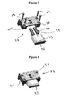
- a hospital bed 1 embodying the invention includes a deck 2 for supporting a mattress or other patient support element.
- the sides of the deck include retaining loops 3 to hold the mattress in position.
- the deck is divided into four sections 4, 5, 6, 7. Three of these 4, 5, 7 are articulated and can be moved by a controller (under the command of the care giver or patient) so as to move the patient support surface between lying down (see figure 2 ) and various seating (see figure 3 ) configurations.
- Articulated beds with a controllable articulation system for the patient support surface are known and not a novel or inventive part of the subject invention so will not be described in detail.
- the hospital bed includes a headboard 8 at a first end and a footboard 9 at a second end.
- the deck 2 is supported on a base frame 10 to which the head 8 and foot boards 9 are mounted.
- the sections 4, 5, 7 of the deck may articulate and move relative to that base frame 10 to take up possible alternative configurations in the known manner (see figures 1 and 3 for examples of alternative deck configurations).
- the base frame 10 has two leg or support structures 11 pivotally coupled to its under surface 12.
- Each leg structure includes a pair of legs 13 each coupled to the base frame 10 by a moveable upper pivot 14 at their deck or upper end.
- the moveable upper pivots 14 can move parallel to the longitudinal axis of the deck and frame (for example, the moveable upper pivot of the left-hand leg in figure 2 can move in the direction shown by arrow B in figure 2 ).
- the legs of each pair of legs are connected together by lower and upper bracing cross-elements 15, 16 at, respectively, the bottom of the legs and at a point of the legs near their mid-points.
- the lower bracing cross-elements 15 are coupled to wheel arrangements 17 for engaging a floor surface, and are connected to the bottoms of their respective legs by lower leg pivots 18 so that they (and the wheels they support) may pivot relative to the respect leg pairs as the legs pivot and the patient support surface is raised and lowered.
- the lower ends of the legs they may be connected to a support frame which itself has wheels.
- the legs or support frame may omit the wheels.
- the upper bracing cross-elements 16 are each pivotally connected to a pair of stabiliser elements 19.
- the stabiliser elements 19, which are each coupled to a leg, are pivotally connected at their first upper ends to the underside of the deck at a fixed upper pivot 20 displaced from the leg upper moveable pivot 19 of the respective leg 13, and are pivotally connected at their second lower ends to the respective pairs of legs at a pair of respective lower stabiliser pivots 21.
- Each of the two upper cross-bracing elements 16 is pivotally connected to a respective pair of stabilisers (and an actuator 22) at actuator pivots 23 on the stabiliser elements.
- Each stabiliser element has a slight kink or bend in its length at the stabiliser portion adjacent the actuator pivot 23. The kink or bend in the stabiliser is to allow room for the cross bars on the underside of the frame i.e. as the legs are moved up alongside the frame (see Figure 7 ).
- An actuator-stabiliser yoke 29 or connection piece is pivotally coupled at a first end to the actuator pivot 23 and thence to the respective upper cross-bracing element 16 and thence indirectly coupled to a respective pair of stabiliser elements 19.
- the actuator-stabiliser yoke 29 is pivotally coupled to an end 25 of an actuator 22 (which may be a hydraulic rod actuator) such that the actuator controllably extends and retracts a rod 26.
- Extension and retraction of the actuator rod 26 causes the respective stabiliser 19 to rotate and hence the leg 13 to rotate relative to the deck 2 and hence raises or lowers the base frame 10 and the patient support surface on the base frame.
- the actuators 22 may be controlled by either the patient or a care-giver.
- Control mechanisms for such actuators are well known and may be either a foot operated pedal, a control panel on the side of the bed, remote control or other control mechanism.
- Suitable actuators are well known and are therefore not described in detail in this application. They may be hydraulic, electric, or pneumatic.
- the bed also includes resilient spring assist elements 27 located in the base frame for engaging the support structure ensemble comprising the stabilisers, actuator-stabiliser yoke and actuator rod as the base frame 10 moves towards and is in its lowermost position (see figures 5 and 6 ).
- resilient spring assist elements 27 located in the base frame for engaging the support structure ensemble comprising the stabilisers, actuator-stabiliser yoke and actuator rod as the base frame 10 moves towards and is in its lowermost position (see figures 5 and 6 ).
- it is the surface of the respective upper bracing element 16 which engages the spring assist element 27 as the bed is lowered to its lowermost position.
- it may be any surface of the support structure which moves up towards the patient support surface as the patient support surface is lowered, and moved downwards away there from as the patient support surface is raised.
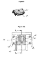
- Each resilient spring assist element 27 includes (see figure 7 ) a housing 28 for attachment to a side or longitudinal portion of to the base frame 10, or some other part if the patient support surface towards which the leg structures move on the bed is lowered (and move away from as the bed is raised) using screws.
- the spring assist elements 27 may be located anywhere on the frame 10 or bed 1 where they engage and interact with a surface of the support or leg structure 11 as this is pivoted up into the underside of the bed and the bed is lowered into its lowermost position.
- a pair of compression springs 30 are located within the housing 28 and their upper ends engage a downwardly facing inner surface 31 in the top of the respective housing 28 (see Figures 7 to 10d ).
- the lower ends of the compression springs 30 engage an upwardly facing inner surface 32 in an engagement member or bolt 33.
- the bolt-like engagement member 33 includes a screw or guide element 34 which runs in a guide 35 in the housing 28.
- the engagement member 33 is biased by the compression springs to extend from the housing by the springs (see figure 8 ) when it is not engaged and being pushed back into the housing. If a force sufficient to overcome the springs is exerted upwardly on the biased engagement member, it can be pushed back into the housing (see figure 9 ).
- the two spring assist elements 27 store energy in the compressed oil springs 30 when these have been biased by the weight of the bed and are in their lowermost position as shown in figure 7 .
- the force exerted by the compressed springs acts against the weight of the bed and thereby effectively reduces the weight which the actuator must overcome when raising the base frame from its lowermost position.
- Figure 11 shows an example of what the actuator force would have to be to raise a bed from its lowermost to its uppermost position at the various heights it must go through. It shows that the force necessary as it is first lifted form the lowermost position is a high one.
- Figure 12 shows how adding in the two spring assist elements described above significantly reduces the initial force required. The example of Figure 11 allows one to achieve this with an actuator which need not produce a force of greater than 6000N. The calculations used to create the examples of Figures 11 and 12 were based on a maximum weight on the bed of 230kg which requires a maximum lifting force of about 8500N.
- the springs used in the example of Figure 12 were coil springs with reference D12670 from the Associated Spring Spec catalog with the properties set out below: LIFT SPRING PARAMETER VALUE UNITS OUTSIDE DIAMETER (OD) 14.50 mm WIRE DIAMETER (d) 2.00 mm FREE LENGTH (FL) 49.50 mm LOAD LENGTH (L1) 23.50 mm SOLID HEIGHT (SH) 21.00 mm LOAD (P) at L1 254 N SPRING RATE (k) 9.81 N/mm MATERIAL MUSIC WIRE --- END CONDITION SQUARED AND GROUND ---
- the embodiment of the invention described above uses a compression spring. Any arrangement which stores energy as it is compressed and then releases it as it then relaxes is suitable.
Abstract
Description
- The present application is concerned with person support apparatus, such as a bed, and with apparatus having a deck and a deck lift system.
- Many person support apparatus, such as hospitals and long-term care (LTC) beds, include a deck and a person support surface or element such as a mattress, supported by the deck. Such beds may also include side rails.
- It is known for person support apparatus such as hospital beds to be provided with lifting systems (often including an hydraulic actuator) which allow the care giver to change the height of the person support surface of the bed, and to articulate a deck under the person support surface so as to modify the configuration of the person support surface. The known arrangements for raising and lowering a person support surface include arrangements in which an hydraulic actuator is coupled to a pivotable supporting structure or leg and the controlled extension of the hydraulic actuator raises the deck surface whereas the controlled retraction of the hydraulic actuator lowers the deck surface by causing deck supporting frame or legs to fold, respectively, away from and towards the underside of the deck. A problem with the known arrangements is that when the deck is in its lowermost position with the supporting structure folded into the underside of the bed, the hydraulic actuator is also folded into the underside of the bed and almost parallel to the deck and therefore perpendicular to the direction in which it must exert a lifting force to counteract gravity and raise the deck and person on the deck. This means that a very high power actuator is (or a number of actuators acting in parallel are) required so that it can provide a force having a sufficiently strong vertical component in the vertical direction to overcome the force of gravity acting on the weight of the bed and anyone supported within the bed. Such high power actuators are relatively expensive and/or bulky, and of course doubling up actuators would also increase costs. A known LTC bed with articulated legs controllably foldable using hydraulic actuators is the Volker 5380 low-height healthcare bed sold by Volker Healthcare (GB) Limited.
US 6,473,922 describes a system for the kinematic motion of an articulated bed which uses a defined bed and support structure geometry to reduce the force necessary to start the legs in motion to raise the bed. -
US 6,405,393 describes a height and angle adjustable bed with a support arm mechanism which provides an initial assist force when the bed is in a nearly or fully lowered position and thereby minimises the force required by the linear actuators used to raise the bed. The arrangement ofUS 6,405,393 includes a compression spring mounted on the support arm adjacent its connection to the bed, to and which moves with the support arm, and engaged by the support arm when the support arm and spring are near the horizontal. The arrangement ofUS 6,405,393 is complicated, prone to failure, requires a powerful spring and presents an entrapment risk for fingers and other body parts. It also cannot be used with a raising and lowering mechanism in which the bottom of the support arm does not move as the bed is raised and lowered. - The present invention provides a patient support as defined in claim 1 to which reference should now be made. Some preferred and/or alternative features are set out in the dependent claims.
- A preferred example of the invention will now be described by way of non-limiting example with reference to the attached figures in which:
-
Figure 1 is a perspective view of a hospital or LTC bed embodying the invention; -
Figure 2 is a side and partially cross-sectional (the left-hand portion of the figure) view of the bed ofFigure 1 with the deck in its uppermost position, and with the deck in its flat position; -
Figure 3 is a side and partially cross-sectional view (similar to that offigure 2 ) of the bed offigure 1 illustrating the deck in an alternative configuration; -
Figure 4 is a side and partially cross-sectional view (similar to that offigure 2 ) of the bed with the deck in a position intermediate its lowermost and uppermost positions; -
Figure 5 is a side and partially cross-sectional view (similar to that offigure 2 ) of the bed with the deck approaching its lowermost position; -
Figure 6 is a side and partially cross-sectional view (similar to that offigure 2 ) of the bed in its lowermost position; -
Figure 7 is an expanded view of the spring arrangement shown inFigures 2 to 6 above; -
Figure 8 is a side view of the spring arrangement in its extended unbiased position such as shown in, for example,Figures 2 ,4 and5 ; -
Figure 9 is a view of the spring arrangement in a compressed and biased position corresponding toFigure 6 ; -
Figures 10a to 10d are, respectively, a rear schematic view of the spring arrangements ofFigures 7 to 9 , a side schematic view of the spring arrangement of -
Figures 7 to 9 , a sectional view along section B-B ofFigure 10b , and a sectional view along section A-A ofFigure 10a ; -
Figure 11 is a graph showing the force the actuator would have to exert to raise the deck in the absence of the spring arrangement; -
Figure 12 is a graph showing the force of the actuator must exert to raise the deck in a system including the spring arrangement. - A hospital bed 1 embodying the invention (see
figure 1 ) includes adeck 2 for supporting a mattress or other patient support element. The sides of the deck includeretaining loops 3 to hold the mattress in position. The deck is divided into foursections 4, 5, 6, 7. Three of these 4, 5, 7 are articulated and can be moved by a controller (under the command of the care giver or patient) so as to move the patient support surface between lying down (seefigure 2 ) and various seating (seefigure 3 ) configurations. Articulated beds with a controllable articulation system for the patient support surface are known and not a novel or inventive part of the subject invention so will not be described in detail. - Referring to
figures 1 and2 , the hospital bed includes aheadboard 8 at a first end and a footboard 9 at a second end. Thedeck 2 is supported on abase frame 10 to which thehead 8 and foot boards 9 are mounted. Thesections 4, 5, 7 of the deck may articulate and move relative to thatbase frame 10 to take up possible alternative configurations in the known manner (seefigures 1 and3 for examples of alternative deck configurations). - The
base frame 10 has two leg orsupport structures 11 pivotally coupled to its undersurface 12. Each leg structure includes a pair oflegs 13 each coupled to thebase frame 10 by a moveableupper pivot 14 at their deck or upper end. The moveableupper pivots 14 can move parallel to the longitudinal axis of the deck and frame (for example, the moveable upper pivot of the left-hand leg infigure 2 can move in the direction shown by arrow B infigure 2 ). - As shown in
figures 1 and2 , the legs of each pair of legs are connected together by lower andupper bracing cross-elements lower bracing cross-elements 15 are coupled to wheel arrangements 17 for engaging a floor surface, and are connected to the bottoms of their respective legs bylower leg pivots 18 so that they (and the wheels they support) may pivot relative to the respect leg pairs as the legs pivot and the patient support surface is raised and lowered. In an alternative embodiment of the invention (not shown) the lower ends of the legs they may be connected to a support frame which itself has wheels. Alternatively, the legs or support frame may omit the wheels. - The
upper bracing cross-elements 16 are each pivotally connected to a pair ofstabiliser elements 19. Thestabiliser elements 19, which are each coupled to a leg, are pivotally connected at their first upper ends to the underside of the deck at a fixed upper pivot 20 displaced from the leg uppermoveable pivot 19 of therespective leg 13, and are pivotally connected at their second lower ends to the respective pairs of legs at a pair of respectivelower stabiliser pivots 21. Each of the twoupper cross-bracing elements 16 is pivotally connected to a respective pair of stabilisers (and an actuator 22) atactuator pivots 23 on the stabiliser elements. Each stabiliser element has a slight kink or bend in its length at the stabiliser portion adjacent theactuator pivot 23. The kink or bend in the stabiliser is to allow room for the cross bars on the underside of the frame i.e. as the legs are moved up alongside the frame (seeFigure 7 ). - An actuator-
stabiliser yoke 29 or connection piece is pivotally coupled at a first end to theactuator pivot 23 and thence to the respectiveupper cross-bracing element 16 and thence indirectly coupled to a respective pair ofstabiliser elements 19. The actuator-stabiliser yoke 29 is pivotally coupled to anend 25 of an actuator 22 (which may be a hydraulic rod actuator) such that the actuator controllably extends and retracts arod 26. Extension and retraction of theactuator rod 26 causes therespective stabiliser 19 to rotate and hence theleg 13 to rotate relative to thedeck 2 and hence raises or lowers thebase frame 10 and the patient support surface on the base frame. The actuators 22 may be controlled by either the patient or a care-giver. Control mechanisms for such actuators are well known and may be either a foot operated pedal, a control panel on the side of the bed, remote control or other control mechanism. Suitable actuators are well known and are therefore not described in detail in this application. They may be hydraulic, electric, or pneumatic. - The bed also includes resilient
spring assist elements 27 located in the base frame for engaging the support structure ensemble comprising the stabilisers, actuator-stabiliser yoke and actuator rod as thebase frame 10 moves towards and is in its lowermost position (seefigures 5 and 6 ). In the described embodiment, there is aspring assist element 27 to engage eachleg 13 and thence interact with each actuator 22. Only one support structure and corresponding spring assist element is described as the support structure and spring assist mechanism are the same for each of the two support structures. In the embodiment shown in the attached figures it is the surface of the respectiveupper bracing element 16 which engages thespring assist element 27 as the bed is lowered to its lowermost position. In alternative embodiments, it may be any surface of the support structure which moves up towards the patient support surface as the patient support surface is lowered, and moved downwards away there from as the patient support surface is raised. - Each resilient
spring assist element 27 includes (seefigure 7 ) ahousing 28 for attachment to a side or longitudinal portion of to thebase frame 10, or some other part if the patient support surface towards which the leg structures move on the bed is lowered (and move away from as the bed is raised) using screws. Thespring assist elements 27 may be located anywhere on theframe 10 or bed 1 where they engage and interact with a surface of the support orleg structure 11 as this is pivoted up into the underside of the bed and the bed is lowered into its lowermost position. A pair ofcompression springs 30 are located within thehousing 28 and their upper ends engage a downwardly facinginner surface 31 in the top of the respective housing 28 (seeFigures 7 to 10d ). The lower ends of the compression springs 30 engage an upwardly facinginner surface 32 in an engagement member orbolt 33. The bolt-like engagement member 33 includes a screw or guideelement 34 which runs in a guide 35 in thehousing 28. Theengagement member 33 is biased by the compression springs to extend from the housing by the springs (seefigure 8 ) when it is not engaged and being pushed back into the housing. If a force sufficient to overcome the springs is exerted upwardly on the biased engagement member, it can be pushed back into the housing (seefigure 9 ). - Referring to
figures 2 ,4 ,5 and 6 , when theactuator rod 26 is fully extended (as shown infigure 2 ), thedeck 2 is in its uppermost or highest position. As therod 26 is retracted (seefigure 2 ), thestabiliser 19 is pivoted about its fixed pivot 20 in the direction shown by arrow A, and the uppermoveable pivot 14 moves in the direction shown by arrow B, and the base frame 10 (and deck mounted thereon) is lowered. As thebase frame 10 approaches its lowermost position (seefigure 5 ) the upper surface of the upper bracingelement 16 on each leg structure contacts the bottom 36 of each of thebiased engagement members 33 of each of the two spring assistelements 27. As the base frame is lowered further, the weight of the deck and base frame (and anything supported thereon) compresses and biases the two compression springs 30 (seefigure 6 ) of each of the spring assist elements. As shown infigure 6 , when the base frame is in is lowermost position the actuator 22 is in an almost horizontal orientation. That means that the direction in which the actuator rod force acts is almost perpendicular to the vertical direction in which gravity acts and therefore has only a small vertical component to counter-act and overcome gravity when the base frame 10 (and the bed and any patient on the beds patient support surface) is to be raised from its lowermost position. - However, the two spring assist
elements 27 store energy in the compressed oil springs 30 when these have been biased by the weight of the bed and are in their lowermost position as shown infigure 7 . The force exerted by the compressed springs acts against the weight of the bed and thereby effectively reduces the weight which the actuator must overcome when raising the base frame from its lowermost position. -
Figure 11 shows an example of what the actuator force would have to be to raise a bed from its lowermost to its uppermost position at the various heights it must go through. It shows that the force necessary as it is first lifted form the lowermost position is a high one.Figure 12 shows how adding in the two spring assist elements described above significantly reduces the initial force required. The example ofFigure 11 allows one to achieve this with an actuator which need not produce a force of greater than 6000N. The calculations used to create the examples ofFigures 11 and12 were based on a maximum weight on the bed of 230kg which requires a maximum lifting force of about 8500N. The springs used in the example ofFigure 12 were coil springs with reference D12670 from the Associated Spring Spec catalog with the properties set out below:LIFT SPRING PARAMETER VALUE UNITS OUTSIDE DIAMETER (OD) 14.50 mm WIRE DIAMETER (d) 2.00 mm FREE LENGTH (FL) 49.50 mm LOAD LENGTH (L1) 23.50 mm SOLID HEIGHT (SH) 21.00 mm LOAD (P) at L1 254 N SPRING RATE (k) 9.81 N/mm MATERIAL MUSIC WIRE --- END CONDITION SQUARED AND GROUND --- - The embodiment of the invention described above uses a compression spring. Any arrangement which stores energy as it is compressed and then releases it as it then relaxes is suitable.
Claims (12)
- A patient support comprising
a frame;
a deck supported by the frame;
a support structure for supporting the frame, the support structure including at least one support element having an upper portion pivotally coupled to the frame at an upper support element pivot, and at least one actuator configured to move between a first and a second position to controllably pivot the support element relative to the frame between a first uppermost raised position and a second lowermost lowered position wherein the support element subtends a smaller angle relative to the frame in the second lowered position than when it is in the first raised position;
an energy storage mechanism for storing energy as the frame is lowered, and for using that stored energy as the frame is raised;
wherein
the energy storage mechanism comprises a spring arrangement located on the frame and having a downwardly facing resilient spring surface, the patient support includes an upwardly facing spring engagement surface which moves with the support element, and wherein the spring engagement surface contacts the spring surface as the frame approaches and reaches its lowermost position to thereby compress the spring arrangement as the frame is lowered to its lowermost position, and wherein the compressed spring acts to push the spring surface against the spring engagement surface as the frame is raised away from the second lowermost lowered position. - A patient support according to claim 1 wherein the downwardly facing spring surface is substantially horizontal.
- A patient support according to any preceding claim wherein the spring arrangement is a compression spring arrangement.
- A patient support according to any preceding claim wherein the energy storage mechanism comprises a housing having a first internal surface, a bolt element projecting from and slideable relative to the housing, and a compression spring having a first end against the first internal surface and a second end against the bolt element so that the spring biases the bolt to extend from the housing and engage the spring engagement surface as the frame approaches and reaches its lowermost position.
- A patient support according to any preceding claim wherein the actuator includes a moveable element having a first end pivotally coupled to the support element , the actuator moveable element actuator being controllably extendable and retractable to pivot the support element relative to the frame between the first uppermost raised position and the second lowermost lowered position.
- A patient support according to claim 5 wherein the support element includes a stabiliser element , a lower portion of the stabiliser being pivotally coupled to an intermediate portion of the support element at a lower stabiliser pivot and the upper portion of the stabiliser element being pivotally coupled to the frame at an upper stabiliser pivot.
- A patient support according to any preceding claim wherein the actuator moveable element is coupled to a portion of the stabiliser proximal the support element.
- A patient support according to claim 7 wherein the actuator and stabiliser are coupled by a connection element, a first portion of the connection element being pivotally connected to the stabiliser and a second portion being pivotally connected to the actuator moveable element.
- A patient support according to any preceding claim wherein the upper support element pivot is moveable in a direction parallel to the longitudinal axis of the support element.
- A patient support according to claim 6 and claim 9 wherein the upper stabiliser pivot is at a fixed position on the frame.
- A patient support according to any preceding claim wherein the support structure includes two support elements coupled by at least one bracing element and wherein a portion of the bracing element is the spring engagement surface.
- A patient support according to claim 11 and either of claims 7 or 8, wherein the actuator moveable element is pivotally connected to the bracing element, and the bracing element is pivotally connected to the two stabilisers, at a portion of the two
stabilisers proximal their respective lower stabiliser pivot.
Priority Applications (1)
| Application Number | Priority Date | Filing Date | Title |
|---|---|---|---|
| EP13305302.5A EP2777672B1 (en) | 2013-03-15 | 2013-03-15 | Person support apparatus |
Applications Claiming Priority (1)
| Application Number | Priority Date | Filing Date | Title |
|---|---|---|---|
| EP13305302.5A EP2777672B1 (en) | 2013-03-15 | 2013-03-15 | Person support apparatus |
Publications (2)
| Publication Number | Publication Date |
|---|---|
| EP2777672A1 true EP2777672A1 (en) | 2014-09-17 |
| EP2777672B1 EP2777672B1 (en) | 2016-11-23 |
Family
ID=48083075
Family Applications (1)
| Application Number | Title | Priority Date | Filing Date |
|---|---|---|---|
| EP13305302.5A Not-in-force EP2777672B1 (en) | 2013-03-15 | 2013-03-15 | Person support apparatus |
Country Status (1)
| Country | Link |
|---|---|
| EP (1) | EP2777672B1 (en) |
Cited By (1)
| Publication number | Priority date | Publication date | Assignee | Title |
|---|---|---|---|---|
| JP2017099677A (en) * | 2015-12-02 | 2017-06-08 | フランスベッド株式会社 | Lifting/lowering drive unit and bed apparatus |
Families Citing this family (3)
| Publication number | Priority date | Publication date | Assignee | Title |
|---|---|---|---|---|
| US10489661B1 (en) | 2016-03-08 | 2019-11-26 | Ocuvera LLC | Medical environment monitoring system |
| US10600204B1 (en) | 2016-12-28 | 2020-03-24 | Ocuvera | Medical environment bedsore detection and prevention system |
| US20210177679A1 (en) * | 2019-12-16 | 2021-06-17 | Stryker Corporation | Patient support with lift assembly |
Citations (5)
| Publication number | Priority date | Publication date | Assignee | Title |
|---|---|---|---|---|
| US6405393B2 (en) | 2000-05-01 | 2002-06-18 | Michael W. Megown | Height and angle adjustable bed having a rolling base |
| US6473922B1 (en) | 1999-09-15 | 2002-11-05 | Sunrise Medical Hhg Inc. | Kinematic motion of articulated bed |
| US20030172459A1 (en) * | 2000-09-29 | 2003-09-18 | Roussy Richard Brian | Height adjustable bed and automatic leg stabilizer system therefor |
| US20050251916A1 (en) * | 2004-05-13 | 2005-11-17 | Adan Elizondo | Collapsible lower structure for beds |
| WO2012066580A2 (en) * | 2010-11-19 | 2012-05-24 | Sundaram Medical Devices (P) Ltd | Hospital bed |
-
2013
- 2013-03-15 EP EP13305302.5A patent/EP2777672B1/en not_active Not-in-force
Patent Citations (5)
| Publication number | Priority date | Publication date | Assignee | Title |
|---|---|---|---|---|
| US6473922B1 (en) | 1999-09-15 | 2002-11-05 | Sunrise Medical Hhg Inc. | Kinematic motion of articulated bed |
| US6405393B2 (en) | 2000-05-01 | 2002-06-18 | Michael W. Megown | Height and angle adjustable bed having a rolling base |
| US20030172459A1 (en) * | 2000-09-29 | 2003-09-18 | Roussy Richard Brian | Height adjustable bed and automatic leg stabilizer system therefor |
| US20050251916A1 (en) * | 2004-05-13 | 2005-11-17 | Adan Elizondo | Collapsible lower structure for beds |
| WO2012066580A2 (en) * | 2010-11-19 | 2012-05-24 | Sundaram Medical Devices (P) Ltd | Hospital bed |
Cited By (1)
| Publication number | Priority date | Publication date | Assignee | Title |
|---|---|---|---|---|
| JP2017099677A (en) * | 2015-12-02 | 2017-06-08 | フランスベッド株式会社 | Lifting/lowering drive unit and bed apparatus |
Also Published As
| Publication number | Publication date |
|---|---|
| EP2777672B1 (en) | 2016-11-23 |
Similar Documents
| Publication | Publication Date | Title |
|---|---|---|
| US11813214B2 (en) | Patient support lift assembly | |
| US8474076B2 (en) | Adjustable foot section for a patient support apparatus | |
| US10188567B2 (en) | Hospital chair beds with extendable/retractable foot sections | |
| US8321976B1 (en) | Height adjustable apparatus with control arm | |
| AU2009201485B2 (en) | High/low bed | |
| JP6916278B2 (en) | Double roller compact actuation system for adjustable beds | |
| EP2777672B1 (en) | Person support apparatus | |
| CA3040756C (en) | Adjustable bed lift mechanism | |
| AU2017218516B2 (en) | Ultra-compact profile actuation system for an adjustable bed | |
| EP2361595A2 (en) | Height adjustable bed with a push chain assembly | |
| EP2314267B1 (en) | Hospital bed with adjustable sleeping surface | |
| US20160120327A1 (en) | Bed apparatus | |
| US11471346B2 (en) | Long term care bed | |
| EP2873400B1 (en) | Person support apparatus | |
| US20140237723A1 (en) | Adjustable bed | |
| US7849538B1 (en) | Height adjustable apparatus | |
| KR101216395B1 (en) | A Foldable Type Bed | |
| JP5304440B2 (en) | Reclining bed drive | |
| CN105310844B (en) | Bed surface vertical lifting mechanism and bed with bed surface vertical lifting function | |
| EP2873399B1 (en) | Person support apparatus | |
| US9572736B2 (en) | Adjustable bed with improved shear reducing mechanism | |
| EP3804684B1 (en) | Lifting assembly | |
| CN219538726U (en) | Lifting mechanism for multifunctional supporting appliance | |
| AU2008101281A4 (en) | High/low bed | |
| CN220607901U (en) | Double-drive telescopic bed frame and double-drive telescopic bed |
Legal Events
| Date | Code | Title | Description |
|---|---|---|---|
| PUAI | Public reference made under article 153(3) epc to a published international application that has entered the european phase |
Free format text: ORIGINAL CODE: 0009012 |
|
| 17P | Request for examination filed |
Effective date: 20130315 |
|
| AK | Designated contracting states |
Kind code of ref document: A1 Designated state(s): AL AT BE BG CH CY CZ DE DK EE ES FI FR GB GR HR HU IE IS IT LI LT LU LV MC MK MT NL NO PL PT RO RS SE SI SK SM TR |
|
| AX | Request for extension of the european patent |
Extension state: BA ME |
|
| R17P | Request for examination filed (corrected) |
Effective date: 20150317 |
|
| RBV | Designated contracting states (corrected) |
Designated state(s): AL AT BE BG CH CY CZ DE DK EE ES FI FR GB GR HR HU IE IS IT LI LT LU LV MC MK MT NL NO PL PT RO RS SE SI SK SM TR |
|
| RIC1 | Information provided on ipc code assigned before grant |
Ipc: A61G 7/012 20060101AFI20150728BHEP Ipc: A61G 7/018 20060101ALI20150728BHEP Ipc: A61G 7/015 20060101ALN20150728BHEP |
|
| GRAP | Despatch of communication of intention to grant a patent |
Free format text: ORIGINAL CODE: EPIDOSNIGR1 |
|
| INTG | Intention to grant announced |
Effective date: 20151013 |
|
| RIC1 | Information provided on ipc code assigned before grant |
Ipc: A61G 7/012 20060101AFI20160217BHEP Ipc: A61G 7/018 20060101ALI20160217BHEP Ipc: A61G 7/015 20060101ALN20160217BHEP |
|
| GRAP | Despatch of communication of intention to grant a patent |
Free format text: ORIGINAL CODE: EPIDOSNIGR1 |
|
| INTG | Intention to grant announced |
Effective date: 20160425 |
|
| RIC1 | Information provided on ipc code assigned before grant |
Ipc: A61G 7/012 20060101AFI20160415BHEP Ipc: A61G 7/018 20060101ALI20160415BHEP Ipc: A61G 7/015 20060101ALN20160415BHEP |
|
| GRAS | Grant fee paid |
Free format text: ORIGINAL CODE: EPIDOSNIGR3 |
|
| GRAA | (expected) grant |
Free format text: ORIGINAL CODE: 0009210 |
|
| AK | Designated contracting states |
Kind code of ref document: B1 Designated state(s): AL AT BE BG CH CY CZ DE DK EE ES FI FR GB GR HR HU IE IS IT LI LT LU LV MC MK MT NL NO PL PT RO RS SE SI SK SM TR |
|
| REG | Reference to a national code |
Ref country code: GB Ref legal event code: FG4D |
|
| REG | Reference to a national code |
Ref country code: CH Ref legal event code: EP |
|
| REG | Reference to a national code |
Ref country code: IE Ref legal event code: FG4D |
|
| REG | Reference to a national code |
Ref country code: AT Ref legal event code: REF Ref document number: 847197 Country of ref document: AT Kind code of ref document: T Effective date: 20161215 |
|
| REG | Reference to a national code |
Ref country code: DE Ref legal event code: R096 Ref document number: 602013014359 Country of ref document: DE |
|
| REG | Reference to a national code |
Ref country code: FR Ref legal event code: PLFP Year of fee payment: 5 |
|
| PG25 | Lapsed in a contracting state [announced via postgrant information from national office to epo] |
Ref country code: LV Free format text: LAPSE BECAUSE OF FAILURE TO SUBMIT A TRANSLATION OF THE DESCRIPTION OR TO PAY THE FEE WITHIN THE PRESCRIBED TIME-LIMIT Effective date: 20161123 |
|
| REG | Reference to a national code |
Ref country code: LT Ref legal event code: MG4D |
|
| REG | Reference to a national code |
Ref country code: NL Ref legal event code: MP Effective date: 20161123 |
|
| REG | Reference to a national code |
Ref country code: AT Ref legal event code: MK05 Ref document number: 847197 Country of ref document: AT Kind code of ref document: T Effective date: 20161123 |
|
| PG25 | Lapsed in a contracting state [announced via postgrant information from national office to epo] |
Ref country code: LT Free format text: LAPSE BECAUSE OF FAILURE TO SUBMIT A TRANSLATION OF THE DESCRIPTION OR TO PAY THE FEE WITHIN THE PRESCRIBED TIME-LIMIT Effective date: 20161123 Ref country code: GR Free format text: LAPSE BECAUSE OF FAILURE TO SUBMIT A TRANSLATION OF THE DESCRIPTION OR TO PAY THE FEE WITHIN THE PRESCRIBED TIME-LIMIT Effective date: 20170224 Ref country code: NL Free format text: LAPSE BECAUSE OF FAILURE TO SUBMIT A TRANSLATION OF THE DESCRIPTION OR TO PAY THE FEE WITHIN THE PRESCRIBED TIME-LIMIT Effective date: 20161123 Ref country code: NO Free format text: LAPSE BECAUSE OF FAILURE TO SUBMIT A TRANSLATION OF THE DESCRIPTION OR TO PAY THE FEE WITHIN THE PRESCRIBED TIME-LIMIT Effective date: 20170223 Ref country code: SE Free format text: LAPSE BECAUSE OF FAILURE TO SUBMIT A TRANSLATION OF THE DESCRIPTION OR TO PAY THE FEE WITHIN THE PRESCRIBED TIME-LIMIT Effective date: 20161123 |
|
| PG25 | Lapsed in a contracting state [announced via postgrant information from national office to epo] |
Ref country code: FI Free format text: LAPSE BECAUSE OF FAILURE TO SUBMIT A TRANSLATION OF THE DESCRIPTION OR TO PAY THE FEE WITHIN THE PRESCRIBED TIME-LIMIT Effective date: 20161123 Ref country code: HR Free format text: LAPSE BECAUSE OF FAILURE TO SUBMIT A TRANSLATION OF THE DESCRIPTION OR TO PAY THE FEE WITHIN THE PRESCRIBED TIME-LIMIT Effective date: 20161123 Ref country code: ES Free format text: LAPSE BECAUSE OF FAILURE TO SUBMIT A TRANSLATION OF THE DESCRIPTION OR TO PAY THE FEE WITHIN THE PRESCRIBED TIME-LIMIT Effective date: 20161123 Ref country code: RS Free format text: LAPSE BECAUSE OF FAILURE TO SUBMIT A TRANSLATION OF THE DESCRIPTION OR TO PAY THE FEE WITHIN THE PRESCRIBED TIME-LIMIT Effective date: 20161123 Ref country code: PT Free format text: LAPSE BECAUSE OF FAILURE TO SUBMIT A TRANSLATION OF THE DESCRIPTION OR TO PAY THE FEE WITHIN THE PRESCRIBED TIME-LIMIT Effective date: 20170323 Ref country code: AT Free format text: LAPSE BECAUSE OF FAILURE TO SUBMIT A TRANSLATION OF THE DESCRIPTION OR TO PAY THE FEE WITHIN THE PRESCRIBED TIME-LIMIT Effective date: 20161123 Ref country code: PL Free format text: LAPSE BECAUSE OF FAILURE TO SUBMIT A TRANSLATION OF THE DESCRIPTION OR TO PAY THE FEE WITHIN THE PRESCRIBED TIME-LIMIT Effective date: 20161123 |
|
| PG25 | Lapsed in a contracting state [announced via postgrant information from national office to epo] |
Ref country code: EE Free format text: LAPSE BECAUSE OF FAILURE TO SUBMIT A TRANSLATION OF THE DESCRIPTION OR TO PAY THE FEE WITHIN THE PRESCRIBED TIME-LIMIT Effective date: 20161123 Ref country code: RO Free format text: LAPSE BECAUSE OF FAILURE TO SUBMIT A TRANSLATION OF THE DESCRIPTION OR TO PAY THE FEE WITHIN THE PRESCRIBED TIME-LIMIT Effective date: 20161123 Ref country code: SK Free format text: LAPSE BECAUSE OF FAILURE TO SUBMIT A TRANSLATION OF THE DESCRIPTION OR TO PAY THE FEE WITHIN THE PRESCRIBED TIME-LIMIT Effective date: 20161123 Ref country code: CZ Free format text: LAPSE BECAUSE OF FAILURE TO SUBMIT A TRANSLATION OF THE DESCRIPTION OR TO PAY THE FEE WITHIN THE PRESCRIBED TIME-LIMIT Effective date: 20161123 Ref country code: DK Free format text: LAPSE BECAUSE OF FAILURE TO SUBMIT A TRANSLATION OF THE DESCRIPTION OR TO PAY THE FEE WITHIN THE PRESCRIBED TIME-LIMIT Effective date: 20161123 |
|
| REG | Reference to a national code |
Ref country code: DE Ref legal event code: R097 Ref document number: 602013014359 Country of ref document: DE |
|
| PG25 | Lapsed in a contracting state [announced via postgrant information from national office to epo] |
Ref country code: IT Free format text: LAPSE BECAUSE OF FAILURE TO SUBMIT A TRANSLATION OF THE DESCRIPTION OR TO PAY THE FEE WITHIN THE PRESCRIBED TIME-LIMIT Effective date: 20161123 Ref country code: SM Free format text: LAPSE BECAUSE OF FAILURE TO SUBMIT A TRANSLATION OF THE DESCRIPTION OR TO PAY THE FEE WITHIN THE PRESCRIBED TIME-LIMIT Effective date: 20161123 Ref country code: BE Free format text: LAPSE BECAUSE OF FAILURE TO SUBMIT A TRANSLATION OF THE DESCRIPTION OR TO PAY THE FEE WITHIN THE PRESCRIBED TIME-LIMIT Effective date: 20161123 Ref country code: BG Free format text: LAPSE BECAUSE OF FAILURE TO SUBMIT A TRANSLATION OF THE DESCRIPTION OR TO PAY THE FEE WITHIN THE PRESCRIBED TIME-LIMIT Effective date: 20170223 |
|
| PLBE | No opposition filed within time limit |
Free format text: ORIGINAL CODE: 0009261 |
|
| STAA | Information on the status of an ep patent application or granted ep patent |
Free format text: STATUS: NO OPPOSITION FILED WITHIN TIME LIMIT |
|
| REG | Reference to a national code |
Ref country code: CH Ref legal event code: PL |
|
| 26N | No opposition filed |
Effective date: 20170824 |
|
| PG25 | Lapsed in a contracting state [announced via postgrant information from national office to epo] |
Ref country code: MC Free format text: LAPSE BECAUSE OF FAILURE TO SUBMIT A TRANSLATION OF THE DESCRIPTION OR TO PAY THE FEE WITHIN THE PRESCRIBED TIME-LIMIT Effective date: 20161123 Ref country code: SI Free format text: LAPSE BECAUSE OF FAILURE TO SUBMIT A TRANSLATION OF THE DESCRIPTION OR TO PAY THE FEE WITHIN THE PRESCRIBED TIME-LIMIT Effective date: 20161123 |
|
| REG | Reference to a national code |
Ref country code: IE Ref legal event code: MM4A |
|
| PG25 | Lapsed in a contracting state [announced via postgrant information from national office to epo] |
Ref country code: LU Free format text: LAPSE BECAUSE OF NON-PAYMENT OF DUE FEES Effective date: 20170315 |
|
| REG | Reference to a national code |
Ref country code: FR Ref legal event code: PLFP Year of fee payment: 6 |
|
| PG25 | Lapsed in a contracting state [announced via postgrant information from national office to epo] |
Ref country code: CH Free format text: LAPSE BECAUSE OF NON-PAYMENT OF DUE FEES Effective date: 20170331 Ref country code: LI Free format text: LAPSE BECAUSE OF NON-PAYMENT OF DUE FEES Effective date: 20170331 Ref country code: IE Free format text: LAPSE BECAUSE OF NON-PAYMENT OF DUE FEES Effective date: 20170315 |
|
| PG25 | Lapsed in a contracting state [announced via postgrant information from national office to epo] |
Ref country code: MT Free format text: LAPSE BECAUSE OF NON-PAYMENT OF DUE FEES Effective date: 20170315 |
|
| PGFP | Annual fee paid to national office [announced via postgrant information from national office to epo] |
Ref country code: GB Payment date: 20190222 Year of fee payment: 7 Ref country code: DE Payment date: 20190219 Year of fee payment: 7 |
|
| PGFP | Annual fee paid to national office [announced via postgrant information from national office to epo] |
Ref country code: FR Payment date: 20190220 Year of fee payment: 7 |
|
| PG25 | Lapsed in a contracting state [announced via postgrant information from national office to epo] |
Ref country code: HU Free format text: LAPSE BECAUSE OF FAILURE TO SUBMIT A TRANSLATION OF THE DESCRIPTION OR TO PAY THE FEE WITHIN THE PRESCRIBED TIME-LIMIT; INVALID AB INITIO Effective date: 20130315 |
|
| PG25 | Lapsed in a contracting state [announced via postgrant information from national office to epo] |
Ref country code: CY Free format text: LAPSE BECAUSE OF NON-PAYMENT OF DUE FEES Effective date: 20161123 |
|
| PG25 | Lapsed in a contracting state [announced via postgrant information from national office to epo] |
Ref country code: MK Free format text: LAPSE BECAUSE OF FAILURE TO SUBMIT A TRANSLATION OF THE DESCRIPTION OR TO PAY THE FEE WITHIN THE PRESCRIBED TIME-LIMIT Effective date: 20161123 |
|
| PG25 | Lapsed in a contracting state [announced via postgrant information from national office to epo] |
Ref country code: TR Free format text: LAPSE BECAUSE OF FAILURE TO SUBMIT A TRANSLATION OF THE DESCRIPTION OR TO PAY THE FEE WITHIN THE PRESCRIBED TIME-LIMIT Effective date: 20161123 |
|
| PG25 | Lapsed in a contracting state [announced via postgrant information from national office to epo] |
Ref country code: AL Free format text: LAPSE BECAUSE OF FAILURE TO SUBMIT A TRANSLATION OF THE DESCRIPTION OR TO PAY THE FEE WITHIN THE PRESCRIBED TIME-LIMIT Effective date: 20161123 Ref country code: IS Free format text: LAPSE BECAUSE OF FAILURE TO SUBMIT A TRANSLATION OF THE DESCRIPTION OR TO PAY THE FEE WITHIN THE PRESCRIBED TIME-LIMIT Effective date: 20170323 |
|
| REG | Reference to a national code |
Ref country code: DE Ref legal event code: R082 Ref document number: 602013014359 Country of ref document: DE Representative=s name: PRUEFER & PARTNER MBB PATENTANWAELTE RECHTSANW, DE |
|
| REG | Reference to a national code |
Ref country code: DE Ref legal event code: R119 Ref document number: 602013014359 Country of ref document: DE |
|
| PG25 | Lapsed in a contracting state [announced via postgrant information from national office to epo] |
Ref country code: DE Free format text: LAPSE BECAUSE OF NON-PAYMENT OF DUE FEES Effective date: 20201001 Ref country code: FR Free format text: LAPSE BECAUSE OF NON-PAYMENT OF DUE FEES Effective date: 20200331 |
|
| GBPC | Gb: european patent ceased through non-payment of renewal fee |
Effective date: 20200315 |
|
| PG25 | Lapsed in a contracting state [announced via postgrant information from national office to epo] |
Ref country code: GB Free format text: LAPSE BECAUSE OF NON-PAYMENT OF DUE FEES Effective date: 20200315 |