EP2803943A1 - Method for transmitting measurement signals in a machining centre with two or more spindles; measuring probe and receiver for the method - Google Patents
Method for transmitting measurement signals in a machining centre with two or more spindles; measuring probe and receiver for the method Download PDFInfo
- Publication number
- EP2803943A1 EP2803943A1 EP14001583.5A EP14001583A EP2803943A1 EP 2803943 A1 EP2803943 A1 EP 2803943A1 EP 14001583 A EP14001583 A EP 14001583A EP 2803943 A1 EP2803943 A1 EP 2803943A1
- Authority
- EP
- European Patent Office
- Prior art keywords
- mtb
- mta
- probe
- dta1
- dtbn
- Prior art date
- Legal status (The legal status is an assumption and is not a legal conclusion. Google has not performed a legal analysis and makes no representation as to the accuracy of the status listed.)
- Granted
Links
Images


Classifications
-
- G—PHYSICS
- G01—MEASURING; TESTING
- G01B—MEASURING LENGTH, THICKNESS OR SIMILAR LINEAR DIMENSIONS; MEASURING ANGLES; MEASURING AREAS; MEASURING IRREGULARITIES OF SURFACES OR CONTOURS
- G01B5/00—Measuring arrangements characterised by the use of mechanical techniques
- G01B5/004—Measuring arrangements characterised by the use of mechanical techniques for measuring coordinates of points
- G01B5/008—Measuring arrangements characterised by the use of mechanical techniques for measuring coordinates of points using coordinate measuring machines
-
- G—PHYSICS
- G01—MEASURING; TESTING
- G01B—MEASURING LENGTH, THICKNESS OR SIMILAR LINEAR DIMENSIONS; MEASURING ANGLES; MEASURING AREAS; MEASURING IRREGULARITIES OF SURFACES OR CONTOURS
- G01B21/00—Measuring arrangements or details thereof, where the measuring technique is not covered by the other groups of this subclass, unspecified or not relevant
- G01B21/02—Measuring arrangements or details thereof, where the measuring technique is not covered by the other groups of this subclass, unspecified or not relevant for measuring length, width, or thickness
- G01B21/04—Measuring arrangements or details thereof, where the measuring technique is not covered by the other groups of this subclass, unspecified or not relevant for measuring length, width, or thickness by measuring coordinates of points
- G01B21/047—Accessories, e.g. for positioning, for tool-setting, for measuring probes
-
- H—ELECTRICITY
- H04—ELECTRIC COMMUNICATION TECHNIQUE
- H04Q—SELECTING
- H04Q9/00—Arrangements in telecontrol or telemetry systems for selectively calling a substation from a main station, in which substation desired apparatus is selected for applying a control signal thereto or for obtaining measured values therefrom
-
- G—PHYSICS
- G01—MEASURING; TESTING
- G01B—MEASURING LENGTH, THICKNESS OR SIMILAR LINEAR DIMENSIONS; MEASURING ANGLES; MEASURING AREAS; MEASURING IRREGULARITIES OF SURFACES OR CONTOURS
- G01B2210/00—Aspects not specifically covered by any group under G01B, e.g. of wheel alignment, caliper-like sensors
- G01B2210/58—Wireless transmission of information between a sensor or probe and a control or evaluation unit
Definitions
- a machining center is a machine tool equipped for automated operation with a CNC control for the complete machining of (metal, wood or plastic) workpieces.
- a tool or a workpiece can be mounted on each of the two spindles; the spindles may be fixedly positioned or, for example, moved and driven in three orthogonal directions X, Y, Z within a working space of the machining center.
- Machining centers usually have an automatic tool and workpiece changer, which - initiated by the CNC control - can switch a probe into the respective spindle and change it in order to also measure the workpiece machined with this spindle.
- the tool can be moved by the machine tool into a measuring space, an area specified for the measurement, a contact or contactless operating button.
- the non-contact button detects the proximity of a surface, for example, with a capacitive, inductive or optical device.
- the touching button detects a surface when in contact with it.
- contact and contactless probes pass corresponding measurement data to a numerical machine controller, which may include a computer program. Together with machine position information from the controller, the probe measurement data allows the numerical controller, such as a CNC controller, to obtain an accurate picture of the dimensions of the tool or workpiece.
- the DE 102 62 188 A1 relates to a multidirectional probe with a housing in which an annular support bearing is formed, which defines an X, Y bearing plane and a normal Z axis of the probe to normal.
- a Tastrich technique is centrally located to receive a stylus.
- a transmission member is slidably guided in the housing along the central axis Z in order to implement any deflections of the support body from its rest position into rectilinear movements.
- a sensor converts the movements of the transmission element into measuring signals.
- the transmission of the measurement signals from a probe to a stationary receiving part is wireless either by optical signals or by radio signals.
- the probes in a machining center come from the same manufacturer and work identically. If the two measuring probes use the same transmission channel synchronously, the simultaneous operation of the two measuring probes leads to unwanted signal collisions.
- Optical systems use light signals of different wavelengths for the two probes and radio systems use different carrier frequencies.
- a disadvantage of these systems is that a separate receiver is required for each transmission channel, which increases the costs for the entire system.
- a channel separation between the two available transmission channels is in practice great difficulties in optical systems, since it can come to mutual interference between the two transmission channels.
- Optical probes are usually activated by a flash of light emitted into the workspace of the machining center where the two probes are located. Thus, these two probes are also activated at the same time. A targeted successive activation of the two probes by directed light flashes is practically impossible. If the two flashes of light overlap, there is no guarantee that both probes will be activated. Even if optical systems can be selectively activated with a light flash signal assigned to the respective measuring probe, it is then also necessary to measure sequentially with the two measuring probes. Since the measuring procedure has to be carried out twice, the entire measuring time is considerably extended.
- the two probes can also work with different modulation frequencies.
- the disadvantage of this approach is that while two receiving parts are needed.
- the demodulator for the lower modulation frequency is very easily disturbed by the higher modulation frequency.
- a probing process ie a transition of the probe from its non-deflected position in its deflected position, as soon as possible by means of a status message to the receiving part and from there to the machine control to be transmitted.
- the status messages should always be transmitted to the machine control with as much as possible the same transmission time. From one measurement to the next, different transmission times of the status messages from a probe to the receiver lead to a falsification of the measurement results. Therefore, it is not possible for the two probes to repeat the transmission of their respective status messages to the receiving part until the status messages are correctly received by the receiving part at random.
- a wireless probe z. B. the probe TC60 of the applicant can be used.
- Such a probe can transmit the measuring signals in a very time-efficient and reliable way in the automatic determination of workpiece position, workpiece position and workpiece dimensions in machining centers.
- each individual bit of the radio-transmitted measuring signal is spread over the entire frequency band, and not, as usual with touch probes of other manufacturers, the measurement signal in the channel hopping or fixed channel assignment transmitted. This is the transmission particularly insensitive to interference.
- the synchronous transmission of measuring signals is not provided with this technique either.
- the method presented here is used to transmit data telegrams at least two, each to be included in a spindle of a machining center probe.
- the data telegrams are transmitted by the respective measuring probe via a common transmission channel for reception by the receiving part.
- two or more data telegrams are transmitted, each of which comprises a characteristic of the respective probe information, a characteristic of the particular probe identifier, and an ordinal number of the respective data telegram with which the characteristic information is sent for each probe.
- a substantially constant cycle time elapses.
- the pause time between the data telegrams is different for each of the respective probes depending on a number of communicating with the receiving part probe in the machining center, the cycle time of each of the probes between two of their data telegrams with the same ordinal number and / or a transmission time for a single one of the data telegrams ,
- the thus organized transmission of the data telegrams ensures that for each of the probes at least one of its data telegrams is not affected by a data telegram of other probes.
- this receiving part can communicate at least one of the data telegrams of all in the processing center with this receiving part via a single transmission channel Receive and evaluate the probe separately from the other data telegrams. For each measurement of a probe two or more data telegrams with different ordinal numbers are sent.
- the approach presented here allows parallel operation and thus (at least nearly) simultaneous measurement with two or more probes communicating with a single, stationary receiver over a single transmission channel.
- an activation signal is sent to the respective measuring probes before the data telegrams are transmitted.
- the transmission of the data telegrams can be initiated by the respective probe.
- an evaluation of the data telegrams after their receipt by the receiving part, and outputting a characteristic of the respective measurement signal output signal can be provided by the receiving part to a numerical control of the machining center.
- each of the probes can be activated by means of a dedicated activation signal for the respective probe.
- each of the probes can be activated by means of a common activation signal for all, a single receiving part associated probe.
- the or each of the activation signals can be transmitted to the measuring probes either by the receiving part and / or by the numerical control of the machining center.
- the (status) information characteristic of the particular probe can be deflected according to a variant depending on the presence of one of two operating modes "normal operation” and “trigger operation", the states (i) “probe is in rest position", (ii) “probe "and / or the states (iii)” Probe probe battery is good “(iv)” Probe probe battery is (nearly) empty “, and / or” Switching point 1 "," Switching point 2 "" Switching point n " , include.
- the probes can emit their data telegrams in predetermined time intervals to the receiving part according to a variant after their activation.
- the receiving part monitored according to a variant in particular in the operating mode "normal operation" of the probe, the receiving part, whether a communication with the probes continuously exists, and / or if the state "Battery of the probe is good” in "battery of the probe is empty” for one of Probe has changed. If this is the case, it can be provided according to a variant that a characteristic warning signal for this is emitted by the receiving part.
- the cycle time between two (successive) of its data telegrams is at least approximately identical to the same ordinal number, ie for different measurements.
- the transmission time of the data telegrams is at least approximately identical for all data telegrams of all measuring probes.
- the number of data telegrams may change according to a variant, for example: In normal operation, for example, two data telegrams are sent out, for example, three data telegrams are transmitted in trigger operation.
- the cycle times of all probes and the pause time between the data telegrams of each of the probes are preferably to be determined so that the sum of the transmission times of all first data telegrams of the other probes is less than or equal to the pause time between the data telegrams of the respective probe.
- the cycle times of all probes can be set to different lengths in both "normal operation” and “trigger operation” operating modes.
- this security phase can be about 1 to 3% of the transmission time of a data telegram, depending on the total transmission time for a single one of the data telegrams, for example. This further reduces the risk of collision of the data telegrams.
- the cycle times and the pause times between two of their respective data telegrams with the same ordinal number for each of the probes are known according to a variant.
- each characteristic of each probe can be set, each of the probes, the cycle times of all probes can be entered or selected, and each of the probes, the pause times for consecutive data telegrams of all probes can be entered or selected ,
- a trigger event occurs which, for example, results in reaching the "switching point 1", the “switching point 2" ... or the “switching point n” or “the probe is at rest", "Probe is deflected” may include.
- This trigger event causes the respective probe to change from “normal mode” to "trigger mode”;
- the receiving part of this trigger event should be informed as quickly and safely as possible, so that the receiving part of this trigger event with a constant and known delay time can be sent to the CNC control of the machining center.
- a switching signal can then be generated by the receiving part according to a variant in the "trigger mode", which can be forwarded to the CNC control and used there together with the - known there - spindle feed to determine a result of the workpiece measurement.
- Trigger mode is essential according to a variant that for high accuracy in the workpiece measurement, the transition of the probe from its undeflected position in its deflected position - or vice versa - as fast as a data telegram reaches the receiver, where it is evaluated, and is transferred from there to the machine control.
- the one characteristic for the particular probe information ie the state transition of the probe
- a characteristic of the particular probe identifier ie for example, which number / address the probe has
- an ordinal number of the respective data telegram with which the characteristic information for the respective probe is sent.
- each probe transmits the data telegrams in triplicate, whereby in each case the ordinal number of the respective data telegram is increased by one. It is essential here according to a variant that each of the data telegrams is sent in a defined time frame, which is different for each probe. This temporal grid is set for all probes as a whole so that even with time offset and not within the cycle times predictable time of sending the individual data telegrams by other probe at least one of the three data telegrams each probe not temporally conflict with other and therefore arrive undisturbed at the receiving part can.
- the temporal sequence of the data telegrams of each individual probe and the pauses between them, as well as the time sequences of the data telegrams of all probes can be designed according to a variant such that in a defined period, so for example a cycle time, always at least one data telegram each probe of data telegrams other probe is transmitted undisturbed to the receiving part.
- a time sequence of 11 time slots is provided.
- Each of the 11 time slots is as long as the transmission time for a single one of the data telegrams plus, if necessary, a processing time for the processing of the data telegram on the part of the receiving part and / or the probe.
- one measuring probe in the 1st, 3rd and 9th time slots and the other measuring probe in the 1st, 5th and 9th time slots can transmit.
- one of the probes in the 1st, 3rd and 5th timeslots and the other probe in the 1st, 5th and 11th time slots can transmit.
- the time sequence of eleven time slots begins for each of the probes with the transmission of its first data telegram.
- the first probe starts the measurement cycle, it sends in the 1st, 3rd, and 5th time slots. If the second probe starts exactly one time slot later, its first data telegram falls exactly between the 1st and 3rd timeslot of the first probe. Thus, the two data telegrams of both probes can be evaluated immediately and without delay from the receiving part and forwarded.
- This distribution of the three data telegrams on the eleven time slots ensures that even with a time-offset transmission of the respective three data telegrams by the two probes at least one data telegram each probe does not collide with other data telegrams of the other probe time.
- the receiving part can be evaluated in a variant by the receiving part based on the ordinal number of the data telegram, whether the first, the second, or the third data telegram was received undisturbed by a probe. Based on this, in a variant by the receiving part prior to the retransmission of the characteristic information from the data telegram corresponding delay times are met to keep the time between a probing on the workpiece and output of the switching signal by the receiving part always at least approximately constant.
- the respective measuring probes and the receiving part can communicate with one another via a common transmission channel, a free radio link, or a free light path-bound common transmission channel.
- each probe is adapted to be recorded in each case in a spindle of the machining center.
- Each probe has a housing in which a support bearing is formed, which defines an X, Y bearing plane and a normal central axis Z of the probe.
- a Taststart technique is centrally located to receive a stylus and a transmission member is slidably guided in the housing along the central axis Z in order to implement any deflections of the support body from its rest position into rectilinear movements.
- a sensor converts the movements of the transmission element into measurement signals, which are processed in a probe-side signal processing unit for transmission to a receiving part.
- the signal processing unit is set up and programmed to transmit data telegrams via a common transmission channel assigned to all the receiving part for reception by the receiving part according to the method described above.
- a receiving part is also presented here for the purpose of receiving measuring signals of at least two measuring probes, each of which is to be recorded in a spindle of a machining center, obtained in measurements taken jointly.
- the receiving part is set up to determine whether the first, the second, or the third data telegram has been received by a probe, and corresponding delay times are maintained before retransmission of the characteristic information from the data telegram to the time between probing the workpiece and output the switching signal by the receiving part always keep at least approximately constant.
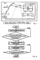
- Fig. 1 schematically illustrates a machining center BAZ with two spindles SA, SB, with which a workpiece WS is machined (milled, drilled, or the like.) In the operation of the machining center BAZ.
- the machining center BAZ has a CNC control.
- the two spindles SA, SB are here in three orthogonal directions X, Y, Z within a working space of the machining center relative to the workpiece WS movable and driven.
- two workpieces can be machined simultaneously, or on the workpiece WS both spindles SA, SB can work simultaneously as shown here.
- the measuring probes MTA, MTB shown here are touching; they each detect a (workpiece) surface upon contact with it. For each detected feature, the probes MTA, MTB output corresponding measurement signals.
- a probe of the applicant is for example in the DE 102 62 188 A1 discloses the contents of which is hereby incorporated by reference.
- the transmission of the measuring signals from each of the measuring probes MTA, MTB to a stationary receiving part ET takes place wirelessly either by optical signals or by radio signals.
- the procedure described below for signal transmission between the two measuring probes MTA, MTB and the stationary receiving part ET makes it possible for them to use the same transmission channel ÜK.
- the transmission channel ÜK is a light path, use the two probes MTAA, MTB light signals of the same wavelength and modulation schemes; If the transmission channel ÜK is a radio link, the two measuring probes MTA, MTB use the same carrier frequencies and modulation schemes. This makes it possible for both measuring probes MTAA, MTB to communicate with one and the same stationary receiving part ET via a transmission channel ÜK.
- Probe A Transmission channel ÜK ⁇ Receiver ET Probe B ⁇
- Fig. 2a shows a flowchart of a method variant presented here for generating and transmitting the data telegrams.
- Fig. 2b the expiration of the data telegram creation.
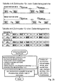
- Upper table ⁇ tA is the time between data telegram 1 and data telegram 2 from probe MTA S1 the data telegram 1 sent by the probe MTA S2 the data telegram 2, sent by probe MTA ⁇ t cycle the cycle time after which the next sequence of data telegrams is sent.
- Lower table ⁇ tB is the time between data telegram 1 and data telegram 2 from probe MTB S1 the data telegram 1 sent by the probe MTB S2 the data telegram 2 sent by the probe MTB ⁇ t cycle the cycle time after which the next sequence of data telegrams is sent.
- the transmission cycle ⁇ t cycle is the same for the probe MTA and for the probe MTB.
- the transmission distance between the 1st and the 2nd data telegram is different for the two probes MTA, MTB and is dimensioned so that even with the simultaneous transmission start of the two probes MTA, MTB always a data telegram is transmitted undisturbed.
- the time slots in which the data telegrams of a measuring probe and the pauses inserted between them are located are the table with a time pattern for three data telegrams.
- Each time slot 1 ... 11 has a transmission length of a data telegram plus, if necessary, a decoding time for the processing of the data telegram.
- RL denotes the rest position of the measuring probes MTA, MTB, and S1, S2, S3 are the three data telegrams.
- a measuring probe MTA in the 1st, 3rd and 9th time slots see upper line of variant 1
- the other measuring probe MTB in the 1st, 5 and 9th time slots see lower line of FIG Version 1
- the one probe sends MTA in the 1st, 3rd and 5th time slots (see upper line of variant 2), and the other probe in the 1st, 5th and 11th time slots (see the lower line of the Variant 2).
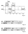
- timing diagram for the data transfer operation presented here is to be noted in a transition from a normal operation in a trigger mode that a telegram in the rest position RL at any time before a data message DT1 can occur, that is unsynchronized to the data message DT1 occurs. Therefore, sending the data telegrams twice would not be sufficient in all scenarios; rather, further precautions must be taken (for example, to send out a third data telegram).
- a third data telegram DT3 of the first probe MTA is arranged so that a sequence of two data telegrams of the second probe MTB would fit into the gap.
- the data telegrams of the first probe MTA occupy time slot 1, time slot 3 and time slot 9
- the data telegrams of the second probe MTB occupy time slot 1, time slot 5, time slot 9 (see the in Fig. 2e shown timing diagram).
- contents of the disturbed data telegrams DTB1 and DTB2 of the second probe MTB are transmitted undisturbed in the third data telegram DTB3.
- Fig. 3 is a situation illustrated in normal operation, being transmitted through the different cycle times of the data telegrams of the two probes MTA, MTB, the respective resting telegrams RLA, RLB undisturbed in the rule.
- the Fig. 3a - 3d show different transmission scenarios in a process variant with two data telegrams, as it can be used for example in normal mode.
- DTXn The individual data telegrams are denoted here by DTXn, where X stands for A or B depending on the probe, and n for the ordinal number 1 or 2 of the data telegram.
- TÜ refers to the transmission time of a single data telegram.
- a substantially constant cycle time ⁇ t cycle elapses.
- a probe MTA, MTB with different atomic number n each passes a substantially constant pause time ⁇ t PauseA , ⁇ t PauseB .
- the pause time .DELTA.t pause A , .DELTA.t pause B between the data telegrams for each of the respective probes is depending on the number of communicating with the receiving part ET probe MTA, MTB - here two - in the machining center BAZ, the cycle time .DELTA.t cycle of each of the probes MTA, MTB between two of its data telegrams DTA1, DTB1 ... DTAn, DTBn with the same ordinal number n and the transmission time TÜ for a single one of the data telegrams DTA1, DTB1 ... DTAn, DTBn different.
- Fig. 4a illustrated situation is that in Fig. 2b shown time pattern for three data telegrams in the variant 1, the last sent rest position data telegrams RL are illustrated as a basis for the following transmission scenarios.
- Fig. 4a and the following Fig. 4b - 4f t Skip marks the time in the sequence of data telegrams on which a respective probe touches the workpiece. At this time t Skip is changed from normal operation to trigger operation and the probe starts sending the sequence of data telegrams for trigger operation.
- Fig. 4a and the following Fig. 4b - 4f t Out denotes the time at which the receiving part ( Fig. 5 , ET) forwards the received status to the machine control (CNC).
- CNC machine control
- the approach presented here ensures that, on the one hand, the time difference between the times t Skip and t Out is as short as possible and, on the other hand, that this time difference is the same in all cases.
- the in Fig. 4b illustrated situation with which the in Fig. 2b shown time pattern for three data telegrams in the variant 1 are the last sent rest position data telegrams RL and the data telegrams DTA1, BTB1 disturbed.
- the switching point data telegrams DTA2, BTB2 are transmitted delayed and therefore correctly received by the receiving part ET.
- the signal output CA of the receiving part ET to the CNC control for the probe MTA is active after a delay time of 8 time grids connected.
- the signal output CB of the receiving part ET to the CNC control for the probe MTB is activated after a delay time of 8 time grids.
- the switching point of the probe MTA in the data telegram DTA1 collides with the rest position data telegram RL-B of the probe MTB. All subsequent data telegrams of the measuring probes MTA and MTB can be received correctly by the receiving part ET.
- the signal output CA of the receiving part ET to the CNC control for the probe MTA is activated after a delay time of 6 time frames after receiving / decoding the data telegram DTA2 of the first probe MTA active.
- the signal output CB of the receiving part ET to the CNC control for the probe MTB is switched to active after a delay time of 8 time frames after receiving / decoding the first data telegram DTB1 the second probe MTB.
- the switching point of the first probe MTA in the data telegram DTA1 collides with the rest position data telegram RL-B of the second probe MTB, as well as the data telegrams DTB1 and DTA2 of the first and second probes MTA, MTB.
- the second data telegram DTB2 of the second measuring probe MTB and the third data telegram DTA3 of the first measuring probe MTA can be received correctly by the receiving part ET.
- the signal output CA of the receiving part ET to the CNC control for the probe MTA is activated immediately after receiving / decoding the third data telegram DTA3 of the first probe MTA active.
- the signal output CB of the receiving part ET to the CNC control for the probe MTB is switched to active after a delay time of 4 time frames after receiving / decoding the second data telegram DTB2 the second probe MTB.
- Fig. 4e illustrated situation collide the two rest position data telegrams RL-A and RL-B of the first and second probe MTA, MTB, and the first data telegrams DTA1, DTB1 the first and second probes MTA, MTB.
- the second data telegrams DTA2, DTB2 of the first and second measuring probes MTA, MTB can be received correctly by the receiving part ET.
- the signal output CA of the receiving part ET to the CNC control for the probe MTA is activated after a delay time of 6 time frames after receiving / decoding the third data telegram DTA3 of the first probe MTA active.
- the signal output CB of the receiving part ET to the CNC control for the probe MTB is activated after a delay time of 4 time frames after receiving / decoding the second data telegram DTB2 the second probe MTB.
- the rest position data telegram RL-B and the first data telegram DTB1 of the first probe MTB collide with the rest position data telegram RL-A of the first probe MTA, and the second data telegrams DTA2, DTB2 of the first and second probes MTA, MTB.
- the first data telegram DTA1 of the first measuring probe MTA and the third data telegrams DTA3, DTB3 of the first and second measuring probes MTA, MTB can be received correctly by the receiving part ET.
- the signal output CA of the receiving part ET to the CNC control for the probe MTA is activated after a delay time of 8 time frames after receiving / decoding the first data telegram DTA1 the first probe MTA active.
- the signal output CB of the receiving part ET to the CNC control for the probe MTB is activated immediately after receiving / decoding the third data telegram DTB3 of the second probe MTB active.
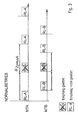
- Fig. 5 are also specially adapted and suitable for transmitting measured signals obtained in measurements carried out together with at least one further measuring probe in a machining center.
- Each probe adapted to each be included in a spindle of the machining center.
- Each probe has a housing in which a support bearing is formed, which defines an X, Y bearing plane and a normal central axis Z of the probe.
- a Tastrich technique is centrally located to receive a stylus and a transmission member is slidably guided in the housing along the central axis Z in order to implement any deflections of the support body from its rest position into rectilinear movements.
- a sensor converts the movements of the transmission element into measurement signals which are processed in a probe-side signal conditioning unit SAE for transmission to a receiving part ET.
- the signal conditioning unit SAE is set up and programmed to transmit data telegrams via a common transmission channel assigned to all the receiving part ET for reception by the receiving part ET. In each case two or more data telegrams are transmitted by the signal conditioning unit SAE of the respective probe MTA, MTB ... MTm. become.
- Each of the data telegrams comprises a characteristic for the respective probe information, a characteristic of the particular probe identifier, and an ordinal number of the respective data telegram, with which the characteristic information for the respective probe is transmitted.
- the signal conditioning unit SAE of the respective probe ensures that a substantially constant cycle time elapses between the beginning of two data telegrams of a probe with the same ordinal number.
- the signal conditioning unit SAE of the respective probe also ensures that a substantially constant pause time elapses between successive data telegrams of a probe with a different ordinal number.
- the signal processing unit of the respective probe ensures that the pause time between the data telegrams for each of the respective probes depending on a number of communicating with the receiving part probe in the machining center, the cycle time of each of the probes between two of their data telegrams with the same atomic number and / or a transmission time for a single one of the data telegrams is different.
- Each of the measuring probes can be equipped with a switch in order to be able to switch the signal conditioning unit SAE of the respective measuring probe between the different sequences of the data telegrams.
- the receiving part ET signal with a corresponding assignment send out to program the signal conditioning unit SAE of each probe accordingly.
Abstract
Das hier vorgestellte Verfahren dient zur Übertragung von Datentelegrammen wenigstens zweier, jeweils in einer Spindel eines Bearbeitungszentrums aufzunehmender Messtaster. Dabei werden die Datentelegramme durch den jeweiligen Messtaster über einen gemeinsamen Übertragungskanal zum Empfang durch das Empfangsteil ausgesendet. Jeweils zwei oder mehr Datentelegramme werden ausgesendet, von denen jedes eine für den jeweiligen Messtaster charakteristische Information, eine für den jeweiligen Messtaster charakteristische Kennnung, und eine Ordnungszahl des jeweiligen Datentelegramms umfasst, mit dem die charakteristische Information für den jeweiligen Messtaster ausgesendet wird. Zwischen dem Beginn zweier Datentelegramme eines Messtasters mit der gleichen Ordnungszahl verstreicht eine im Wesentlichen konstante Zykluszeit. Zwischen aufeinander folgenden Datentelegrammen eines Messtasters mit unterschiedlicher Ordnungszahl verstreicht jeweils eine im Wesentlichen konstante Pausenzeit. Die Pausenzeit zwischen den Datentelegrammen ist für jeden der jeweiligen Messtaster in Abhängigkeit von einer Anzahl der mit dem Empfangsteil kommunizierenden Messtaster in dem Bearbeitungszentrum, der Zykluszeit jedes der Messtaster zwischen zwei ihrer Datentelegramme mit der gleichen Ordnungszahl und/oder einer Übertragungszeit für ein einzelnes der Datentelegramme unterschiedlich.The method presented here is used to transmit data telegrams at least two, each to be included in a spindle of a machining center probe. The data telegrams are transmitted by the respective probe via a common transmission channel for reception by the receiving part. In each case two or more data telegrams are transmitted, each of which comprises a characteristic of the respective probe information, a characteristic of the particular probe identification, and an ordinal number of the respective data telegram with which the characteristic information is sent for each probe. Between the beginning of two data telegrams of a probe having the same ordinal number, a substantially constant cycle time elapses. Between successive data telegrams of a probe with different atomic number each passes a substantially constant pause time. The pause time between the data telegrams is different for each of the respective probes depending on a number of communicating with the receiving part probe in the machining center, the cycle time of each of the probes between two of their data telegrams with the same ordinal number and / or a transmission time for a single one of the data telegrams ,
Description
Hier wird ein Verfahren zur Übertragung von Messsignalen in Bearbeitungszentren mit zwei oder mehr Spindeln beschrieben. Außerdem werden die entsprechenden Vorrichtungskomponenten wie die Messtaster und ein entsprechender Empfänger erläutert. Details hierzu sind in den Ansprüchen definiert; aber auch die Beschreibung enthält relevante Angaben zur Struktur und zur Funktionsweise sowie zu Varianten des Verfahrens und den Vorrichtungskomponenten.Here a method for the transmission of measuring signals in machining centers with two or more spindles is described. In addition, the corresponding device components such as the probes and a corresponding receiver will be explained. Details are defined in the claims; but also the description contains relevant information on the structure and functioning as well as variants of the method and the device components.
In Bearbeitungszentren mit zwei Spindeln wird mit jeder Spindel ein Werkstück bearbeitet. Ein Bearbeitungszentrum ist eine Werkzeugmaschine, die für einen automatisierten Betrieb mit einer CNC-Steuerung zur Komplettbearbeitung von (Metall-, Holz-, oder Kunststoff-) Werkstücken ausgerüstet ist. An jeder der beiden Spindeln kann ein Werkzeug oder ein Werkstück montiert sein; die Spindeln können fest positioniert oder zum Beispiel in drei orthogonalen Richtungen X, Y, Z innerhalb eines Arbeitsraums des Bearbeitungszentrums bewegt und angetrieben werden. In einem Bearbeitungszentrum mit zwei Spindeln können zum Beispiel zwei Werkstücke gleichzeitig bearbeitet werden. Bearbeitungszentren haben in der Regel einen automatischen Werkzeug- und Werkstückwechsler, der - von der CNC-Steuerung veranlasst - einen Messtaster in die jeweilige Spindel ein- und auswechseln kann, um das mit dieser Spindel bearbeitete Werkstück auch zu vermessen.In machining centers with two spindles, one workpiece is machined with each spindle. A machining center is a machine tool equipped for automated operation with a CNC control for the complete machining of (metal, wood or plastic) workpieces. On each of the two spindles, a tool or a workpiece can be mounted; the spindles may be fixedly positioned or, for example, moved and driven in three orthogonal directions X, Y, Z within a working space of the machining center. In a machining center with two spindles, for example, two workpieces can be machined simultaneously. Machining centers usually have an automatic tool and workpiece changer, which - initiated by the CNC control - can switch a probe into the respective spindle and change it in order to also measure the workpiece machined with this spindle.
Das Werkzeug kann durch die Werkzeugmaschine in einen Messraum, einen zur Messung festgelegten Bereich, eines berührend oder berührungslos arbeitenden Tasters bewegt werden. Der berührungslos funktionierende Taster detektiert die Nähe einer Oberfläche beispielsweise mit einer kapazitiven, induktiven oder optischen Einrichtung. Der berührend funktionierende Taster detektiert eine Oberfläche bei Kontakt mit dieser. Für jedes detektierte Merkmal geben Kontakt- und kontaktlose Taster entsprechende Messdaten an eine numerische Maschinen-Steuerung weiter, die ein Computerprogramm enthalten kann. Zusammen mit Maschinenpositionsinformationen aus der Steuerung ermöglichen die Tastermessdaten, dass die numerische Steuerung, zum Beispiel eine CNC-Steuerung, ein exaktes Bild der Abmessungen des Werkzeugs oder Werkstücks ermitteln kann.The tool can be moved by the machine tool into a measuring space, an area specified for the measurement, a contact or contactless operating button. The non-contact button detects the proximity of a surface, for example, with a capacitive, inductive or optical device. The touching button detects a surface when in contact with it. For each detected feature, contact and contactless probes pass corresponding measurement data to a numerical machine controller, which may include a computer program. Together with machine position information from the controller, the probe measurement data allows the numerical controller, such as a CNC controller, to obtain an accurate picture of the dimensions of the tool or workpiece.
Die
Die Übertragung der Messsignale von einem Messtaster zu einem stationären Empfangsteil erfolgt drahtlos entweder durch optische Signale oder durch Funksignale.The transmission of the measurement signals from a probe to a stationary receiving part is wireless either by optical signals or by radio signals.
Üblicherweise sind in einem Bearbeitungszentrum entsprechend der Anzahl der Spindeln auch Messtaster vorgesehen, die in die jeweilige Spindel zur Werkstückvermessung eingesetzt werden können.Usually, in a machining center according to the number of spindles and probes are provided, which can be used in the respective spindle for workpiece measurement.
Für Bearbeitungszentren mit zwei Spindeln existiert nun die Anforderung, dass in einem Messablauf gleichzeitig bearbeitete Werkstücke auch gleichzeitig gemessen werden können.For machining centers with two spindles, there is now the requirement that simultaneously machined workpieces can be measured simultaneously in a single measurement run.
In der Regel kommen die Messtaster in einem Bearbeitungszentrum vom selben Hersteller und funktionieren identisch. Wenn nun die beiden Messtaster synchron denselben Übertragungskanal nutzen, kommt es durch den gleichzeitigen Betrieb der zwei Messtaster zu unerwünschten Signalkollisionen.As a rule, the probes in a machining center come from the same manufacturer and work identically. If the two measuring probes use the same transmission channel synchronously, the simultaneous operation of the two measuring probes leads to unwanted signal collisions.
Optische Systeme benutzen für die beiden Messtaster Lichtsignale unterschiedlicher Wellenlänge und Funksysteme benutzen unterschiedliche Trägerfrequenzen. Nachteilig an diesen Systemen ist, dass für jeden Übertragungskanal ein eigener Empfangsteil benötigt wird, was die Kosten für das Gesamtsystem steigert.Optical systems use light signals of different wavelengths for the two probes and radio systems use different carrier frequencies. A disadvantage of these systems is that a separate receiver is required for each transmission channel, which increases the costs for the entire system.
Eine Kanaltrennung zwischen den beiden verfügbaren Übertragungskanälen bereitet bei optischen Systemen in der Praxis große Schwierigkeiten, da es zur gegenseitigen Beeinflussung zwischen den beiden Übertragungskanälen kommen kann. Optische Messtaster werden üblicherweise durch einen Lichtblitz aktiviert, der in den Arbeitsraum des Bearbeitungszentrums ausgesendet wird, in dem sich die beiden Messtaster befinden. Damit werden diese beiden Messtaster auch zeitgleich aktiviert. Eine gezielte sukzessive Aktivierung der beiden Messtaster durch gerichtete Lichtblitze ist praktisch nicht möglich. Wenn sich die beiden Lichtblitze überlagern, ist nicht sichergestellt, dass beide Messtaster aktiviert werden. Selbst wenn optische Systeme gezielt mit einem dem jeweiligen Messtaster zugeordneten Lichtblitz-Signal aktiviert werden können, muss dann mit den beiden Messtastern auch sequenziell gemessen werden. Da die Messprozedur doppelt auszuführen ist, verlängert sich die gesamte Messzeit erheblich.A channel separation between the two available transmission channels is in practice great difficulties in optical systems, since it can come to mutual interference between the two transmission channels. Optical probes are usually activated by a flash of light emitted into the workspace of the machining center where the two probes are located. Thus, these two probes are also activated at the same time. A targeted successive activation of the two probes by directed light flashes is practically impossible. If the two flashes of light overlap, there is no guarantee that both probes will be activated. Even if optical systems can be selectively activated with a light flash signal assigned to the respective measuring probe, it is then also necessary to measure sequentially with the two measuring probes. Since the measuring procedure has to be carried out twice, the entire measuring time is considerably extended.
Da optische Systeme in der Regel mit modulierten Lichtsignalen arbeiten, können die beiden Messtaster auch mit unterschiedlichen Modulationsfrequenzen arbeiten. Nachteilig ist bei dieser Vorgehensweise, dass dabei zwei Empfangsteile benötigt werden. Außerdem ist der Demodulator für die niedrigere Modulationsfrequenz sehr leicht durch die höhere Modulationsfrequenz zu stören.Since optical systems usually work with modulated light signals, the two probes can also work with different modulation frequencies. The disadvantage of this approach is that while two receiving parts are needed. In addition, the demodulator for the lower modulation frequency is very easily disturbed by the higher modulation frequency.
Für eine hohe Genauigkeit bei der Werkstückvermessung soll ein Antast-Vorgang, also ein Übergang des Messtasters aus seiner nicht ausgelenkten Lage in seine ausgelenkte Lage, möglichst schnell mittels einer Statusbotschaft zum Empfangsteil und von dort zu der Maschinensteuerung übertragen werden. Dabei sollten die Statusbotschaften stets mit möglichst der gleichen Übertragungszeit an die Maschinensteuerung übertragen werden. Von einer Messung zur nächsten unterschiedliche Übertragungszeiten der Statusbotschaften von einem Messtasters zum Empfangsteil führen zur Verfälschung der Messergebnisse. Daher ist es nicht möglich, dass die beiden Messtaster das Aussenden ihrer jeweiligen Statusbotschaften zum Empfangsteil so oft wiederholen, bis die Statusbotschaften von dem Empfangsteil zufällig richtig empfangen werden.For a high accuracy in workpiece measurement a probing process, ie a transition of the probe from its non-deflected position in its deflected position, as soon as possible by means of a status message to the receiving part and from there to the machine control to be transmitted. The status messages should always be transmitted to the machine control with as much as possible the same transmission time. From one measurement to the next, different transmission times of the status messages from a probe to the receiver lead to a falsification of the measurement results. Therefore, it is not possible for the two probes to repeat the transmission of their respective status messages to the receiving part until the status messages are correctly received by the receiving part at random.
Bekannte Lösungen dieses Problems betreiben die Messtaster auf den beiden, üblicherweise in den Messtastern und dem jeweils zugehörigen Empfänger aktivierbaren, unterschiedlichen Kanälen.Known solutions to this problem operate the probes on the two, usually in the probes and the respective associated receiver activatable, different channels.
In Maschinen mit großen Arbeitsräumen, in der Fünf-Achs-Bearbeitung, oder wenn ein Messtaster in ein Werkstück eintaucht, kann eine optische Sichtverbindung zwischen Messtaster und Empfänger nicht ständig sichergestellt werden. Um auch in solchen Fällen eine zuverlässige Übertragung der Messsignale zu erhalten, kann ein Funk-Messtaster, z. B. der Messtaster TC60 der Anmelderin eingesetzt werden. Ein solcher Messtaster kann bei der automatischen Ermittlung von Werkstückposition, Werkstücklage und Werkstückabmessungen in Bearbeitungszentren sehr zeiteffizient und sicher die Messsignale übertragen. Dabei wird jedes einzelne Bit des per Funk übertragenen Messsignals über das gesamte Frequenzband gespreizt, und nicht, wie bei Messtastern anderer Hersteller üblich, das Messsignal im Kanalsprungverfahren oder mit fester Kanalzuordnung übertragen. Dadurch ist die Übertragung besonders unempfindlich gegen Störeinflüsse. Allerdings ist auch bei dieser Technik die synchrone Aussendung von Messsignalen nicht vorgesehen.In machines with large working spaces, in the five-axis machining, or when a probe dips into a workpiece, an optical line of sight between the probe and receiver can not be constantly ensured. In order to obtain a reliable transmission of the measurement signals in such cases, a wireless probe, z. B. the probe TC60 of the applicant can be used. Such a probe can transmit the measuring signals in a very time-efficient and reliable way in the automatic determination of workpiece position, workpiece position and workpiece dimensions in machining centers. In this case, each individual bit of the radio-transmitted measuring signal is spread over the entire frequency band, and not, as usual with touch probes of other manufacturers, the measurement signal in the channel hopping or fixed channel assignment transmitted. This is the transmission particularly insensitive to interference. However, the synchronous transmission of measuring signals is not provided with this technique either.
Alle bisher verwendeten Ansätze haben in der rauen und schwierig vorhersehbaren Betriebsumgebung eines Bearbeitungszentrums hinsichtlich der Kosten, der Messgenauigkeit, der Zuverlässigkeit, und/oder der Schnelligkeit im Dauerbetrieb nicht überzeugen können.All approaches used so far have not been able to convince in the harsh and difficult to predict operating environment of a machining center in terms of cost, accuracy of measurement, reliability, and / or speed in continuous operation.
In Bearbeitungszentren mit zwei oder mehr synchron arbeitenden und/oder mechanisch gekoppelten Spindeln soll eine präzise, kosten- und zeit-effiziente Werkstückvermessung ermöglicht werden.In machining centers with two or more synchronously operating and / or mechanically coupled spindles a precise, cost and time-efficient workpiece measurement is to be made possible.
Das hier vorgestellte Verfahren dient zur Übertragung von Datentelegrammen wenigstens zweier, jeweils in einer Spindel eines Bearbeitungszentrums aufzunehmender Messtaster. Wie in Anspruch 1 definiert, werden dabei die Datentelegramme durch den jeweiligen Messtaster über einen gemeinsamen Übertragungskanal zum Empfang durch das Empfangsteil ausgesendet. Dabei werden jeweils zwei oder mehr Datentelegramme ausgesendet, von denen jedes eine für den jeweiligen Messtaster charakteristische Information, eine für den jeweiligen Messtaster charakteristische Kennnung, und eine Ordnungszahl des jeweiligen Datentelegramms umfasst, mit dem die charakteristische Information für den jeweiligen Messtaster ausgesendet wird. Zwischen dem Beginn zweier Datentelegramme eines Messtasters mit der gleichen Ordnungszahl verstreicht eine im Wesentlichen konstante Zykluszeit. Zwischen aufeinander folgenden Datentelegrammen eines Messtasters mit unterschiedlicher Ordnungszahl verstreicht jeweils eine im Wesentlichen konstante Pausenzeit. Die Pausenzeit zwischen den Datentelegrammen ist für jeden der jeweiligen Messtaster in Abhängigkeit von einer Anzahl der mit dem Empfangsteil kommunizierenden Messtaster in dem Bearbeitungszentrum, der Zykluszeit jedes der Messtaster zwischen zwei ihrer Datentelegramme mit der gleichen Ordnungszahl und/oder einer Übertragungszeit für ein einzelnes der Datentelegramme unterschiedlich.The method presented here is used to transmit data telegrams at least two, each to be included in a spindle of a machining center probe. As defined in
Das derart organisierte Aussenden der Datentelegramme stellt sicher, dass für jeden der Messtaster zumindest eines seiner Datentelegramme nicht durch ein Datentelegramm anderer Messtaster beeinträchtigt wird. Obwohl nur ein Empfangsteil vorgesehen ist, kann dieses Empfangsteil zumindest jeweils eines der Datentelegramme aller in dem Bearbeitungszentrum mit diesem Empfangsteil über einen einzigen Übertragungskanal kommunizierenden Messtaster zeitlich getrennt von den anderen Datentelegrammen empfangen und auswerten. Für jede Messung eines Messtasters werden zwei oder mehr Datentelegramme mit unterschiedlicher Ordnungszahl versendet.The thus organized transmission of the data telegrams ensures that for each of the probes at least one of its data telegrams is not affected by a data telegram of other probes. Although only one receiving part is provided, this receiving part can communicate at least one of the data telegrams of all in the processing center with this receiving part via a single transmission channel Receive and evaluate the probe separately from the other data telegrams. For each measurement of a probe two or more data telegrams with different ordinal numbers are sent.
Da nur ein (stationäres) Empfangsteil benötigt wird, reduziert dies die Kosten für Anschaffung, Installation und Betrieb der Gesamtanordnung. Außerdem entfällt eine aufwendige und fehleranfällige Kanaltrennung für die Übertragungskanäle der einzelnen Messtaster.Since only one (stationary) receiving part is needed, this reduces the cost of acquisition, installation and operation of the overall arrangement. In addition, a complex and error-prone channel separation for the transmission channels of each probe omitted.
Die hier vorgestellte Vorgehensweise ermöglicht den parallelen Betrieb und somit ein (zumindest nahezu) gleichzeitiges Messen mit zwei oder mehr Messtastern, die mit einem einzigen, stationären Empfangsteil über einen einzigen Übertragungskanal kommunizieren.The approach presented here allows parallel operation and thus (at least nearly) simultaneous measurement with two or more probes communicating with a single, stationary receiver over a single transmission channel.
Zum Initialisieren jedes der Messtaster ist gemäß einer Variante vorgesehen, dass vor dem Aussenden der Datentelegramme ein Aktivierungssignal an die jeweiligen Messtaster gesendet wird. So kann das Aussenden der Datentelegramme durch die jeweiligen Messtaster initiiert werden.To initialize each of the measuring probes, it is provided according to a variant that an activation signal is sent to the respective measuring probes before the data telegrams are transmitted. Thus, the transmission of the data telegrams can be initiated by the respective probe.
Außerdem kann gemäß einer Variante ein Auswerten der Datentelegramme nach deren Empfang durch das Empfangsteil, und ein Ausgeben eines für das das jeweilige Messsignal charakteristischen Ausgangssignals durch das Empfangsteil an eine numerische Steuerung des Bearbeitungszentrums vorgesehen sein.In addition, according to a variant, an evaluation of the data telegrams after their receipt by the receiving part, and outputting a characteristic of the respective measurement signal output signal can be provided by the receiving part to a numerical control of the machining center.
Dabei kann gemäß einer Variante jeder der Messtaster mittels eines dedizierten Aktivierungssignals für den jeweiligen der Messtaster aktiviert werden. Gemäß einer anderen Variante kann jeder der Messtaster mittels eines gemeinsamen Aktivierungssignals für alle, einem einzigen Empfangsteil zugeordneten Messtaster aktiviert werden.In this case, according to a variant, each of the probes can be activated by means of a dedicated activation signal for the respective probe. According to another variant, each of the probes can be activated by means of a common activation signal for all, a single receiving part associated probe.
Das oder jedes der Aktivierungssignale kann dabei je nach Systemarchitektur und Steuerungskonzept des Bearbeitungszentrums entweder von dem Empfangsteil und/ oder von der numerischen Steuerung des Bearbeitungszentrums an die Messtaster ausgesendet werden.Depending on the system architecture and control concept of the machining center, the or each of the activation signals can be transmitted to the measuring probes either by the receiving part and / or by the numerical control of the machining center.
Die für den jeweiligen Messtaster charakteristische (Status-)Information kann gemäß einer Variante in Abhängigkeit vom Vorliegen einer von zwei Betriebsarten "Normalbetrieb" und "Triggerbetrieb", die Zustände (i) "Messtaster ist in Ruhelage", (ii) "Messtaster ist ausgelenkt", und/oder die Zustände (iii) "Batterie des Messtasters ist gut" (iv) "Batterie des Messtasters ist (nahezu) leer", und/oder "Schaltpunkt 1", "Schaltpunkt 2"... "Schaltpunkt n", umfassen.The (status) information characteristic of the particular probe can be deflected according to a variant depending on the presence of one of two operating modes "normal operation" and "trigger operation", the states (i) "probe is in rest position", (ii) "probe "and / or the states (iii)" Probe probe battery is good "(iv)" Probe probe battery is (nearly) empty ", and / or"
Die Messtaster können gemäß einer Variante nach ihrem Aktivieren ihre Datentelegramme in vorbestimmten Zeitintervallen an das Empfangsteil aussenden. Dabei überwacht gemäß einer Variante insbesondere in der Betriebsart "Normalbetrieb" der Messtaster das Empfangsteil, ob eine Kommunikation mit den Messtastern fortwährend besteht, und/oder ob der Zustand "Batterie des Messtasters ist gut" in "Batterie des Messtasters ist leer" für einen der Messtaster gewechselt hat. Sollte dies der Fall sein, kann gemäß einer Variante vorgesehen sein, dass ein hierfür charakteristisches Warnsignal von dem Empfangsteil abgegeben wird.The probes can emit their data telegrams in predetermined time intervals to the receiving part according to a variant after their activation. In this case, monitored according to a variant in particular in the operating mode "normal operation" of the probe, the receiving part, whether a communication with the probes continuously exists, and / or if the state "Battery of the probe is good" in "battery of the probe is empty" for one of Probe has changed. If this is the case, it can be provided according to a variant that a characteristic warning signal for this is emitted by the receiving part.
Für jeden der Messtaster kann gemäß einer Variante vorgesehen sein, dass die Zykluszeit zwischen zwei (aufeinander folgenden) seiner Datentelegramme mit der gleichen Ordnungszahl, also für unterschiedliche Messungen, zumindest annähernd identisch ist.According to a variant, it can be provided for each of the measuring probes that the cycle time between two (successive) of its data telegrams is at least approximately identical to the same ordinal number, ie for different measurements.
Des Weiteren kann gemäß einer Variante vorgesehen sein, dass die Übertragungszeit der Datentelegramme für alle Datentelegramme aller Messtaster zumindest annähernd identisch ist.Furthermore, according to a variant, it may be provided that the transmission time of the data telegrams is at least approximately identical for all data telegrams of all measuring probes.
Sofern zum Beispiel vorgesehen ist, dass (i) genau zwei Messtaster mit einem Empfangsteil über einen einzigen Übertragungskanal kommunizieren, und vorgesehen ist, dass (ii) für jede Messung eines Messtasters genau zwei Datentelegramme an das Empfangsteil gesendet werden, und vorgesehen ist, dass (iii) die Übertragungszeit für ein einzelnes der Datentelegramme von beiden Messtastern gleich lang ist, kann gemäß einer Variante folgendes festgelegt sein:
- a) Die Zykluszeiten der beiden Messtaster zwischen zwei ihrer jeweiligen Datentelegramme mit der gleichen Ordnungszahl sind für die beiden Messtaster identisch und betragen mindestens die siebenfache Übertragungszeit eines einzelnen der Datentelegramme.
- b) Die zu verstreichende Pausenzeit zwischen den Datentelegrammen einer jeweiligen Messung für jeden der jeweiligen Messtaster ist wie folgt unterschiedlich festgelegt:
- (i) Die zu verstreichende Pausenzeit wird so dimensioniert, dass auch bei gleichzeitigem Sendebeginn der beiden Messtaster immer wenigstens eines ihrer Datentelegramme nicht zeitlich überlappend mit einem der Datentelegramme des jeweils anderen Messtasters ausgesendet wird.
- (ii) Die zu verstreichende Pausenzeit zwischen den Datentelegrammen des einen Messtasters beträgt mindestens die einfache Übertragungszeit eines einzelnen der Datentelegramme.
- (iii)Die zu verstreichende Pausenzeit zwischen den Datentelegrammen des anderen Messtasters beträgt höchstens die doppelte Übertragungszeit eines einzelnen der Datentelegramme.
- a) The cycle times of the two probes between two of their respective data telegrams with the same ordinal number are identical for the two probes and amount to at least seven times the transmission time of an individual one of the data telegrams.
- b) The pause time to be passed between the data telegrams of a respective measurement for each of the respective measuring probes is determined differently as follows:
- (i) The pause time to be passed is dimensioned such that at least one of the two is always at the same time when the two probes start transmitting simultaneously Data telegrams are not transmitted in overlapping time with one of the data telegrams of the other probe.
- (ii) The pause time to be passed between the data telegrams of one touch probe is at least the simple transmission time of a single one of the data telegrams.
- (iii) The pause time to be passed between the data telegrams of the other probe is at most twice the transmission time of a single one of the data telegrams.
Es sei verstanden, dass gemäß anderen Variante auch andere Werte für die Zykluszeiten der beiden Messtaster und / oder die Pausenzeiten zwischen den Datentelegrammen des / der jeweils anderen Messtaster festgelegt werden können. Dies gilt insbesondere bei Anwendungen, in denen vorgesehen ist, dass (i) abhängig von der Anzahl der Spindeln im Bearbeitungszentrum mehr als zwei, also zum Beispiel 3, 4, 5 oder 6 Messtaster mit einem einzigen Empfangsteil über einen einzigen Übertragungskanal kommunizieren, und vorgesehen ist, dass (ii) für jede Messung eines Messtasters zwei oder mehr, also zum Beispiel drei, vier, oder fünf Datentelegramme an das Empfangsteil gesendet werden.It should be understood that other values for the cycle times of the two probes and / or the pause times between the data telegrams of the / each other probe can be determined according to another variant. This is especially true in applications where it is envisaged that (i) depending on the number of spindles in the machining center, more than two, for example 3, 4, 5 or 6 probes communicate with a single receiving part via a single transmission channel, and provided is that (ii) two or more, so for example, three, four, or five data telegrams are sent to the receiving part for each measurement of a probe.
In Abhängigkeit vom Vorliegen einer von zwei Betriebsarten "Normalbetrieb" und "Triggerbetrieb" kann sich gemäß einer Variante zum Beispiel auch die Anzahl der Datentelegramme ändern: Im Normalbetrieb werden zum Beispiel zwei Datentelegramme ausgesendet, im Triggerbetrieb werden zum Beispiel drei Datentelegramme ausgesendet.Depending on the presence of one of two operating modes "normal operation" and "trigger operation", the number of data telegrams may change according to a variant, for example: In normal operation, for example, two data telegrams are sent out, for example, three data telegrams are transmitted in trigger operation.
Die Zykluszeiten aller Messtaster und die Pausenzeit zwischen den Datentelegrammen jedes der Messtaster sind gemäß einer Variante zum Beispiel vorzugsweise so zu bestimmen, dass die Summe der Übertragungszeiten aller ersten Datentelegramme der jeweils anderen Messtaster kleiner oder höchstens gleich der Pausenzeit zwischen den Datentelegrammen des jeweiligen Messtasters ist.According to a variant, the cycle times of all probes and the pause time between the data telegrams of each of the probes are preferably to be determined so that the sum of the transmission times of all first data telegrams of the other probes is less than or equal to the pause time between the data telegrams of the respective probe.
Alternativ oder zusätzlich können gemäß einer Variante auch in beiden Betriebsarten "Normalbetrieb" und "Triggerbetrieb" die Zykluszeiten aller Messtaster unterschiedlich lang gesetzt werden. Durch diese Maßnahmen wird erreicht, dass die Datentelegramme aller Messtaster zeitlich so ineinander geschachtelt werden, dass jedenfalls eines der Datentelegramme jedes der Messtaster von anderen Datentelegrammen der anderen Messtaster nicht beeinträchtigt und so für das Empfangsteil auswertbar ist.Alternatively or additionally, according to a variant, the cycle times of all probes can be set to different lengths in both "normal operation" and "trigger operation" operating modes. By these measures it is achieved that the data telegrams of all probes are nested in time so that in any case one of the data telegrams of each of the probes of other data telegrams of the other probe is not affected and can be evaluated for the receiving part.
Im Übrigen kann gemäß einer Variante vorgesehen sein, dass in beiden Betriebsarten "Normalbetrieb" und "Triggerbetrieb" zu Beginn des Aussendens jedes der Datentelegramme jeder der Messtaster eine kurze Sicherheitsphase lang nicht sendet. Diese Sicherheitsphase kann gemäß einer Variante zum Beispiel abhängig von der gesamten Übertragungszeit für ein einzelnes der Datentelegramme etwa 1 - 3 % der Übertragungszeit eines Datentelegramms lang sein. Damit wird das Kollisionsrisiko der Datentelegramme weiter reduziert.Incidentally, it can be provided according to a variant that in both modes "normal operation" and "trigger operation" at the beginning of sending each of the data telegrams each of the probes does not send a short security phase long. According to a variant, this security phase can be about 1 to 3% of the transmission time of a data telegram, depending on the total transmission time for a single one of the data telegrams, for example. This further reduces the risk of collision of the data telegrams.
Auf Seiten des Empfangsteils und jedes der Messtaster sind gemäß einer Variante die Zykluszeiten und die Pausenzeiten zwischen zwei ihrer jeweiligen Datentelegramme mit der gleichen Ordnungszahl für jeden der Messtaster bekannt. Dazu kann gemäß einer Variante in einer Einlernphase aller Messtaster jeweils die charakteristische Kennung jedes der Messtaster festgelegt werden, jedem der Messtaster können die Zykluszeiten aller Messtaster eingegeben oder ausgewählt werden, und jedem der Messtaster können die Pausenzeiten für aufeinander folgende Datentelegramme aller Messtaster eingegeben oder ausgewählt werden.On the part of the receiving part and each of the probes, the cycle times and the pause times between two of their respective data telegrams with the same ordinal number for each of the probes are known according to a variant. For this purpose, according to a variant in a learning phase of all probes each characteristic of each probe can be set, each of the probes, the cycle times of all probes can be entered or selected, and each of the probes, the pause times for consecutive data telegrams of all probes can be entered or selected ,
Der einfachen Handhabung wegen können gemäß einer Variante im Empfangsteil und / oder den Messtastern für mögliche Varianten (zwei bis zum Beispiel sechs Messtaster, und zwei bis zu Beispiel vier Datentelegramme) Tabellen mit passenden Zykluszeiten und Pausenzeiten werkseitig oder bei der ersten Inbetriebnahme hinterlegt sein. Dann muss nur noch jeweils die charakteristische Kennung jedes der Messtaster auf Seiten des Empfangsteils und jedem der Messtaster festgelegt werden.For ease of handling, according to a variant in the receiving part and / or the probes for possible variants (two to example six probes, and two to example four data telegrams) tables with appropriate cycle times and break times are factory or stored at first commissioning. Then only the characteristic identifier of each of the measuring probes on the side of the receiving part and each of the measuring probes has to be defined.
Im Normalbetrieb senden alle Messtaster ihre Datentelegramme zum Empfangsteil. Das Empfangsteil überwacht, ob die Kommunikation mit den Messtastern fortlaufend besteht, wertet den Batteriestatus aus und wertet den Schaltzustand des Messtasters (Ausgelenkt / Ruhelage) aus. Durch die vorstehend erläuterte zeitliche Schachtelung der Datentelegramme wird sichergestellt, dass jeweils eines der Datentelegramme eines Messtasters nicht von Datentelegrammen eines - im Fall zweier Messtaster: des - anderen Messtasters gestört wird.In normal mode, all probes send their data telegrams to the receiving section. The receiver monitors whether the communication with the touch probes is continuous, evaluates the battery status and evaluates the switching status of the probe (deflected / rest position). The temporal nesting of the data telegrams explained above ensures that in each case one of the data telegrams of a touch probe is not disturbed by data telegrams of one - in the case of two touch probes: another touch probe.
Beim jeweiligen Antasten eines Messtasters an seinem jeweiligen Werkstück tritt ein Trigger-Ereignis auf, das zum Beispiel das Erreichen des "Schaltpunkt 1", des "Schaltpunkt 2"... oder des "Schaltpunkt n", oder "Messtaster ist in Ruhelage", "Messtaster ist ausgelenkt" umfassen kann. Dieses Trigger-Ereignis hat zur Folge, dass der jeweilige Messtaster aus der Betriebsart "Normalbetrieb" in die Betriebsart "Triggerbetrieb" wechselt; außerdem soll das Empfangsteil von diesem Trigger-Ereignis so schnell und sicher wir möglich informiert werden, damit von dem Empfangsteil dieses Trigger-Ereignis mit konstanter und bekannter Verzögerungszeit an die CNC-Steuerung des Bearbeitungszentrums ausgesendet werden kann.Whenever a probe is touched on its respective workpiece, a trigger event occurs which, for example, results in reaching the "
Zum Auswerten der Datentelegramme kann gemäß einer Variante auf Seiten des Empfangsteils anhand der Ordnungszahl des jeweils ungestört empfangenen Datentelegramms, den Zykluszeiten und den Pausenzeiten jedes der Messtaster ermittelt werden, wie viel Zeit seit der Erfassung des Messsignals vergangen ist. Aus dieser Information kann gemäß einer Variante dann in der Betriebsart "Triggerbetrieb" vom Empfangsteil ein Schaltsignal generiert werden, das an die CNC-Steuerung weitergeleitet und dort zusammen mit dem - dort bekannten - Spindelvorschub zur Bestimmung eines Ergebnisses der Werkstückvermessung herangezogen werden kann.For evaluating the data telegrams can be determined according to a variant on the part of the receiver based on the ordinal number of each undisturbed received data telegram, the cycle times and pauses of each of the probes, how much time has elapsed since the detection of the measurement signal. From this information, a switching signal can then be generated by the receiving part according to a variant in the "trigger mode", which can be forwarded to the CNC control and used there together with the - known there - spindle feed to determine a result of the workpiece measurement.
In der Betriebsart "Triggerbetrieb" ist gemäß einer Variante wesentlich, dass für eine hohe Genauigkeit bei der Werkstückvermessung der Übergang des Messtasters aus seiner nicht ausgelenkten Lage in seine ausgelenkte Lage - oder umgekehrt - möglichst schnell als Datentelegramm zum Empfangsteil gelangt, dort ausgewertet wird, und von dort an die Maschinensteuerung übertragen wird. Dazu wird hier gemäß einer Variante vorgeschlagen, jeden Zustands-Übergang des Messtasters mit konstanter Verzögerungszeit vom Empfangsteil an die Maschinensteuerung zu übertragen.In the operating mode "trigger mode" is essential according to a variant that for high accuracy in the workpiece measurement, the transition of the probe from its undeflected position in its deflected position - or vice versa - as fast as a data telegram reaches the receiver, where it is evaluated, and is transferred from there to the machine control. For this purpose, it is proposed according to a variant to transmit each state transition of the probe with a constant delay time from the receiving part to the machine control.
Dazu werden gemäß einer Variante in der Betriebsart "Triggerbetrieb" zu jeder Messung mit einem Zustands-Übergang des Messtasters Datentelegramme zusammengestellt, die eine für den jeweiligen Messtaster charakteristische Information, also den Zustands-Übergang des Messtasters, eine für den jeweiligen Messtaster charakteristische Kennnung, also zum Beispiel welche Nummer / Adresse der Messtaster hat, und eine Ordnungszahl des jeweiligen Datentelegramms, mit dem die charakteristische Information für den jeweiligen Messtaster ausgesendet wird.For this purpose, according to a variant in the operating mode "trigger mode" for each measurement with a state transition of the probe data telegrams are put together, the one characteristic for the particular probe information, ie the state transition of the probe, a characteristic of the particular probe identifier, ie for example, which number / address the probe has, and an ordinal number of the respective data telegram with which the characteristic information for the respective probe is sent.
In einer Variante sendet jeder Messtaster die Datentelegramme dreifach aus, wobei jeweils die Ordnungszahl des jeweiligen Datentelegramms um eins erhöht wird. Wesentlich ist hierbei gemäß einer Variante auch, dass jede der Datentelegramme in einem definierten zeitlichen Raster versendet wird, die für jeden Messtaster anders ist. Dieses zeitliche Raster ist für alle Messtaster insgesamt so festgelegt, dass auch bei gegeneinander zeitlich versetztem und innerhalb der Zykluszeiten nicht vorhersehbarem Zeitpunkt des Aussendens der einzelnen Datentelegramme durch andere Messtaster wenigstens eines der drei Datentelegramme jedes Messtasters nicht mit anderen zeitlich kollidiert und deshalb ungestört beim Empfangsteil ankommen kann.In one variant, each probe transmits the data telegrams in triplicate, whereby in each case the ordinal number of the respective data telegram is increased by one. It is essential here according to a variant that each of the data telegrams is sent in a defined time frame, which is different for each probe. This temporal grid is set for all probes as a whole so that even with time offset and not within the cycle times predictable time of sending the individual data telegrams by other probe at least one of the three data telegrams each probe not temporally conflict with other and therefore arrive undisturbed at the receiving part can.
Die zeitliche Abfolge der Datentelegramme jedes einzelnen Messtasters und der Pausen zwischen ihnen, sowie die zeitlichen Abfolgen der Datentelegramme aller Messtaster können gemäß einer Variante derart gestaltet sein, dass in einem definierten Zeitraum, also zum Beispiel einer Zykluszeit, immer mindestens ein Datentelegramm jedes Messtasters von Datentelegrammen anderer Messtaster ungestört an das Empfangsteil übertragen wird.The temporal sequence of the data telegrams of each individual probe and the pauses between them, as well as the time sequences of the data telegrams of all probes can be designed according to a variant such that in a defined period, so for example a cycle time, always at least one data telegram each probe of data telegrams other probe is transmitted undisturbed to the receiving part.
In einer Variante mit drei Datentelegrammen pro Messung für einen Messtaster wird eine zeitliche Abfolge von 11 Zeitschlitzen vorgesehen. Jeder der 11 Zeitschlitze ist so lang wie die Übertragungszeit für ein einzelnes der Datentelegramme zuzüglich ggf. einer Verarbeitungszeit für die Verarbeitung des Datentelegramms auf Seiten des Empfangsteils und / oder des Messtasters.In a variant with three data telegrams per measurement for a probe, a time sequence of 11 time slots is provided. Each of the 11 time slots is as long as the transmission time for a single one of the data telegrams plus, if necessary, a processing time for the processing of the data telegram on the part of the receiving part and / or the probe.
Dabei kann im Fall einer Anordnung von zwei mit dem Empfangsteil kommunizierenden Messtastern der eine Messtaster im 1., 3., und 9. Zeitschlitz, und der andere Messtaster im 1., 5, und 9. Zeitschlitz senden. In einer Alternative dazu kann im Fall einer Anordnung von zwei mit dem Empfangsteil kommunizierenden Messtastern der eine Messtaster im 1., 3., und 5. Zeitschlitz, und der andere Messtaster im 1., 5, und 11. Zeitschlitz senden. Die zeitliche Abfolge von elf Zeitschlitzen beginnt dabei für jeden der Messtaster mit dem Aussenden seines jeweils ersten Datentelegramms.In this case, in the case of an arrangement of two measuring probes communicating with the receiving part, one measuring probe in the 1st, 3rd and 9th time slots and the other measuring probe in the 1st, 5th and 9th time slots can transmit. In an alternative to this, in the case of an arrangement of two probes communicating with the receiving part, one of the probes in the 1st, 3rd and 5th timeslots and the other probe in the 1st, 5th and 11th time slots can transmit. The time sequence of eleven time slots begins for each of the probes with the transmission of its first data telegram.
Wenn nun zum Beispiel der erste Messtaster den Messzyklus beginnt, sendet er im 1., 3., und 5. Zeitschlitz. Falls der zweite Messtaster genau einen Zeitschlitz später beginnt, fällt sein erstes Datentelegramm genau zwischen den 1. und den 3. Zeitschlitz des ersten Messtasters. Somit können die beiden Datentelegramme beider Messtaster sofort und ohne Verzögerung vom Empfangsteil ausgewertet und weitergeleitet werden.If, for example, the first probe starts the measurement cycle, it sends in the 1st, 3rd, and 5th time slots. If the second probe starts exactly one time slot later, its first data telegram falls exactly between the 1st and 3rd timeslot of the first probe. Thus, the two data telegrams of both probes can be evaluated immediately and without delay from the receiving part and forwarded.
Durch zeitliches Verschieben der beiden Zeitschlitz-Schemata gegeneinander ist unmittelbar nachzuvollziehen, dass in jedem Fall zumindest ein Datentelegramm von jedem der beiden Messtaster ungestört an das Empfangsteil gesendet werden kann.By temporally shifting the two timeslot schemes against each other is immediately understand that in any case at least one data message from each of the two probes can be sent undisturbed to the receiving part.
Diese Verteilung der drei Datentelegramme auf die elf Zeitschlitze stellt sicher, dass auch bei zeitlich versetztem Aussenden der jeweiligen drei Datentelegramme durch die beiden Messtaster zumindest ein Datentelegramm jedes Messtasters nicht mit anderen Datentelegrammen des anderen Messtasters zeitlich kollidiert.This distribution of the three data telegrams on the eleven time slots ensures that even with a time-offset transmission of the respective three data telegrams by the two probes at least one data telegram each probe does not collide with other data telegrams of the other probe time.
Sobald das Empfangsteil ein Datentelegramm eines Messtasters ungestört empfangen hat, kann in einer Variante durch das Empfangsteil anhand der Ordnungszahl des Datentelegramm ausgewertet werden, ob von einem Messtaster das erste, das zweite, oder das dritte Datentelegramm ungestört empfangen wurde. Basierend hierauf werden in einer Variante durch das Empfangsteil vor dem Weitersenden der charakteristischen Information aus dem Datentelegramm entsprechende Verzögerungszeiten eingehalten, um die Zeit zwischen einer Antastung am Werkstück und Ausgabe des Schaltsignals durch das Empfangsteil stets zumindest annähernd konstant zu halten.Once the receiving part has received a data telegram of a probe undisturbed, can be evaluated in a variant by the receiving part based on the ordinal number of the data telegram, whether the first, the second, or the third data telegram was received undisturbed by a probe. Based on this, in a variant by the receiving part prior to the retransmission of the characteristic information from the data telegram corresponding delay times are met to keep the time between a probing on the workpiece and output of the switching signal by the receiving part always at least approximately constant.
Die jeweiligen Messtaster und das Empfangsteil können je nach Anwendungsfall oder Einsatzsituation durch einen leitungs-, einen freien funkstrecken-, oder einen freien lichtstrecken-gebundenen gemeinsamen Übertragungskanal miteinander kommunizieren.Depending on the application or the situation of use, the respective measuring probes and the receiving part can communicate with one another via a common transmission channel, a free radio link, or a free light path-bound common transmission channel.
Schließlich wird hier ein Messtaster vorgeschlagen, der auch zur Übertragung von in gemeinsam mit wenigstens einem weiteren Messtaster ausgeführten Messungen gewonnenen Messsignalen in einem Bearbeitungszentrum speziell eingerichtet und geeignet ist. Insbesondere ist jeder Messtaster dazu eingerichtet, jeweils in einer Spindel des Bearbeitungszentrums aufgenommen zu sein. Jeder Messtaster hat ein Gehäuse, in dem ein Stützlager ausgebildet ist, das eine X, Y -Lagerebene und eine dazu normale zentrale Achse Z des Messtasters definiert. An einem Tragkörper ist eine Taststiftaufnahme zentral angeordnet, um einen Taststift aufzunehmen und ein Übertragungsglied ist im Gehäuse entlang der zentralen Achse Z verschiebbar geführt, um beliebige Auslenkungen des Tragkörpers aus seiner Ruhelage in geradlinige Bewegungen umzusetzen. Ein Sensor setzt die Bewegungen des Übertragungsgliedes in Messsignale um, die in einer messtasterseitigen Signalaufbereitungseinheit zum Aussenden an ein Empfangsteil aufbereitet werden. Die Signalaufbereitungseinheit ist dazu eingerichtet und programmiert, Datentelegramme über einen für alle dem Empfangsteil zugeordneten, gemeinsamen Übertragungskanal zum Empfang durch das Empfangsteil gemäß dem oben beschriebenen Verfahren auszusenden.Finally, a measuring probe is proposed here which is also specially set up and suitable for transmitting measuring signals obtained in measurements carried out together with at least one further measuring probe in a machining center. In particular, each probe is adapted to be recorded in each case in a spindle of the machining center. Each probe has a housing in which a support bearing is formed, which defines an X, Y bearing plane and a normal central axis Z of the probe. On a support body a Taststiftaufnahme is centrally located to receive a stylus and a transmission member is slidably guided in the housing along the central axis Z in order to implement any deflections of the support body from its rest position into rectilinear movements. A sensor converts the movements of the transmission element into measurement signals, which are processed in a probe-side signal processing unit for transmission to a receiving part. The signal processing unit is set up and programmed to transmit data telegrams via a common transmission channel assigned to all the receiving part for reception by the receiving part according to the method described above.
Schließlich wird hier auch ein Empfangsteil vorgestellt zum Empfang von in gemeinsam ausgeführten Messungen gewonnenen Messsignalen wenigstens zweier, jeweils in einer Spindel eines Bearbeitungszentrums aufzunehmender Messtaster. Das Empfangsteil ist dazu eingerichtet, zu ermitteln ob von einem Messtaster das erste, das zweite, oder das dritte Datentelegramm empfangen wurde, und entsprechende Verzögerungszeiten vor dem Weitersenden der charakteristischen Information aus dem Datentelegramm eingehalten werden, um die Zeit zwischen einer Antastung am Werkstück und Ausgabe des Schaltsignals durch das Empfangsteil stets zumindest annähernd konstant zu halten.Finally, a receiving part is also presented here for the purpose of receiving measuring signals of at least two measuring probes, each of which is to be recorded in a spindle of a machining center, obtained in measurements taken jointly. The receiving part is set up to determine whether the first, the second, or the third data telegram has been received by a probe, and corresponding delay times are maintained before retransmission of the characteristic information from the data telegram to the time between probing the workpiece and output the switching signal by the receiving part always keep at least approximately constant.
Weitere Ziele, Merkmale, Vorteile und Anwendungsmöglichkeiten ergeben sich aus der nachfolgenden Beschreibung einiger Ausführungsbeispiele und zugehöriger Zeichnungen. Dabei bilden alle beschriebenen und/oder bildlich dargestellten Merkmale für sich oder in beliebiger Kombination den hier offenbarten Gegenstand, auch unabhängig von ihrer Zusammenstellung in der Beschreibung oder der Zeichnungen, oder ihrer Gruppierung in den Ansprüchen oder deren Rückbeziehungen.
-
Fig. 1 zeigt schematisch ein Bearbeitungszentrum, die mit einem Empfangsteil gekoppelt ist, das dazu eingerichtet ist, von mehreren, hier zwei, jeweils in einer Spindel des Bearbeitungszentrums aufgenommene Messtaster Datentelegramme zu empfangen und an eine CNC-Steuerung des Bearbeitungszentrums zu senden. -
Fig. 2a zeigt ein Flussdiagramm einer hier vorgestellten Verfahrensvariante, wobei -
Fig. 2b den Ablauf der Datentelegrammerstellung erläutert. -
Fig. 2c zeigt ein Zeitdiagramm zu dem hier vorgestellten Datenübertragungsbetrieb. -
Fig. 2d zeigt ein weiteres Zeitdiagramm zu dem hier vorgestellten Datenübertragungsbetrieb. -
Fig. 2e zeigt ein weiteres Zeitdiagramm mit verwendeten Zeitschlitzen. -
Fig. 3 zeigt eine Situation im Normalbetrieb.
Fig. 3a - 3d zeigen unterschiedliche Übertragungsszenarien gemäß einer hier vorgestellten Verfahrensvariante. -
Fig. 4a zeigt das inFig. 2b gezeigte Zeitmuster für drei Datentelegramme in derVariante 1. -
Fig. 4b- 4f zeigen unterschiedliche Szenarien mit inFig. 2b gezeigten Zeitmuster für drei Datentelegramme in derVariante 1. -
Fig. 5 veranschaulicht die Situation mit mehreren Messtastern MTA ... MTm, welche über einen gemeinsamen Übertragungskanal zu dem Empfangsteil ET ihre Datentelegramme aussenden. Außerdem veranschaulichtFig. 5 die elektromechanische Funktion der Messtaster.
-
Fig. 1 schematically shows a machining center which is coupled to a receiving part which is adapted to receive from several, here two, each recorded in a spindle of the machining center probe data telegrams and send to a CNC control of the machining center. -
Fig. 2a shows a flowchart of a method variant presented here, wherein -
Fig. 2b explains the process of data telegram creation. -
Fig. 2c shows a timing diagram for the data transfer operation presented here. -
Fig. 2d shows a further timing diagram for the data transmission operation presented here. -
Fig. 2e shows another time chart with time slots used. -
Fig. 3 shows a situation in normal operation.
Fig. 3a - 3d show different transmission scenarios according to a method variant presented here. -
Fig. 4a shows that inFig. 2b shown time pattern for three data telegrams invariant 1. -
Fig. 4b- 4f show different scenarios with inFig. 2b shown time pattern for three data telegrams invariant 1. -
Fig. 5 illustrates the situation with multiple touch probes MTA ... MTm, which send out their data telegrams via a common transmission channel to the receiving part ET. Also illustratedFig. 5 the electromechanical function of the probe.
Die hier gezeigten Messtaster MTA, MTB funktionieren berührend; sie detektieren jeweils eine (Werkstück-)Oberfläche bei Kontakt mit dieser. Für jedes detektierte Merkmal geben die Messtaster MTA, MTB entsprechende Messsignale aus. Ein solcher Messtaster der Anmelderin ist zum Bespiel in der
In der in
Obere Tabelle
Δ tA die Zeit zwischen Datentelegramm 1 und Datentelegramm 2 von Messtaster MTA
S1 das Datentelegramm 1, gesendet von Messtaster MTA
S2 das Datentelegramm 2, gesendet von Messtaster MTA
Δ tZyklus die Zykluszeit, nach der die nächste Folge an Datentelegrammen gesendet wird.Upper table
Δ tA is the time between
S1 the
S2 the
Δ t cycle the cycle time after which the next sequence of data telegrams is sent.
Untere Tabelle
Δ tB ist die Zeit zwischen Datentelegramm 1 und Datentelegramm 2 von Messtaster MTB
S1 das Datentelegramm 1, gesendet von Messtaster MTB
S2 das Datentelegramm 2, gesendet von Messtaster MTB
Δ tZyklus die Zykluszeit, nach der die nächste Folge an Datentelegrammen gesendet wird.Lower table
Δ tB is the time between
S1 the
S2 the
Δ t cycle the cycle time after which the next sequence of data telegrams is sent.
Der Sendezyklus ΔtZyklus ist bei Messtaster MTA und bei Messtaster MTB gleich. Der Sendeabstand zwischen dem 1. und dem 2. Datentelegramm ist für die beiden Messtaster MTA, MTB unterschiedlich und wird so dimensioniert, dass auch bei gleichzeitigem Sendebeginn der beiden Messtaster MTA, MTB immer ein Datentelegramm ungestört übertragen wird.The transmission cycle Δt cycle is the same for the probe MTA and for the probe MTB. The transmission distance between the 1st and the 2nd data telegram is different for the two probes MTA, MTB and is dimensioned so that even with the simultaneous transmission start of the two probes MTA, MTB always a data telegram is transmitted undisturbed.
In der in
Dabei sendet in der Variante 1 der eine Messtaster MTA im 1., 3., und 9. Zeitschlitz (siehe obere Zeile der Variante 1), und der andere Messtaster MTB im 1., 5, und 9. Zeitschlitz (siehe untere Zeile der Variante 1). In einer dazu alternativen Variante 2 sendet der eine Messtaster MTA im 1., 3., und 5. Zeitschlitz (siehe obere Zeile der Variante 2), und der andere Messtaster im 1., 5, und 11. Zeitschlitz (siehe untere Zeile der Variante 2).In this case, in
In dem in
Damit wird gewährleistet, dass DTA1 und DTA2 und DTB1 empfangen werden können. Zwei aufeinander folgende Datentelegramme DTB1 und DTB2 liegen zeitlich so weit auseinander, dass die Kombination aus DTA1 und DTA2 (von MTA) dazwischen passt.This ensures that DTA1 and DTA2 and DTB1 can be received. Two consecutive data telegrams DTB1 and DTB2 are so far apart in time that the combination of DTA1 and DTA2 (of MTA) fits in between.
In dem in
Diese Abfolge wird nicht einfach im gleichen Abstand und Zeitmuster fortgesetzt. Vielmehr wird ein drittes Datentelegramm DT3 des ersten Messtasters MTA so angeordnet, dass eine Abfolge von zwei Datentelegrammen des zweiten Messtasters MTB in den Zwischenraum passen würde. Bei einer hier gewählten Variante, belegen die Datentelegramme des ersten Messtasters MTA Zeitschlitz 1, Zeitschlitz 3 und Zeitschlitz 9, und die Datentelegramme des zweiten Messtasters MTB belegt Zeitschlitz 1, Zeitschlitz 5, Zeitschlitz 9 (siehe das in
In
Die
Die einzelnen Datentelegramme sind hier mit DTXn bezeichnet, wobei X je nach Messtaster für A oder B steht, und n für die Ordnungszahl 1 oder 2 des Datentelegramms.The individual data telegrams are denoted here by DTXn, where X stands for A or B depending on the probe, and n for the
Dabei kollidieren schraffierte Datentelegramme, während die Datentelegramme ohne Schraffur von dem Empfangsteil ET ungestört empfangen werden können. TÜ bezeichnet die Übertragungszeit eines einzelnen Datentelegramms.In this case, hatched data telegrams collide, while the data telegrams without hatching can be received undisturbed by the receiving part ET. TÜ refers to the transmission time of a single data telegram.
Zwischen dem Beginn zweier Datentelegramme eines Messtasters mit der gleichen Ordnungszahl n verstreicht eine im Wesentlichen konstante Zykluszeit ΔtZyklus. Zwischen aufeinander folgenden Datentelegrammen DTA1, DTA2; DTB1, DTB2 eines Messtasters MTA, MTB mit unterschiedlicher Ordnungszahl n verstreicht jeweils eine im Wesentlichen konstante Pausenzeit ΔtPauseA, ΔtPauseB. Die Pausenzeit ΔtPauseA, ΔtPauseB zwischen den Datentelegrammen für jeden der jeweiligen Messtaster ist in Abhängigkeit von der Anzahl der mit dem Empfangsteil ET kommunizierenden Messtaster MTA, MTB - hier zwei - in dem Bearbeitungszentrum BAZ, der Zykluszeit ΔtZyklus jedes der Messtaster MTA, MTB zwischen zwei ihrer Datentelegramme DTA1, DTB1 ... DTAn, DTBn mit der gleichen Ordnungszahl n und der Übertragungszeit TÜ für ein einzelnes der Datentelegramme DTA1, DTB1 ... DTAn, DTBn unterschiedlich.Between the beginning of two data telegrams of a measuring probe with the same ordinal number n, a substantially constant cycle time Δt cycle elapses. Between successive data telegrams DTA1, DTA2; DTB1, DTB2 a probe MTA, MTB with different atomic number n each passes a substantially constant pause time Δt PauseA , Δt PauseB . The pause time .DELTA.t pause A , .DELTA.t pause B between the data telegrams for each of the respective probes is depending on the number of communicating with the receiving part ET probe MTA, MTB - here two - in the machining center BAZ, the cycle time .DELTA.t cycle of each of the probes MTA, MTB between two of its data telegrams DTA1, DTB1 ... DTAn, DTBn with the same ordinal number n and the transmission time TÜ for a single one of the data telegrams DTA1, DTB1 ... DTAn, DTBn different.
In der in
In der
Die hier vorgestellte Vorgehensweise stellt insgesamt sicher, dass einerseits die Zeitdifferenz zwischen den Zeitpunkten tSkip und tOut möglichst kurz ist, und andererseits, dass diese Zeitdifferenz in allen Fällen gleich lang ist.On the whole, the approach presented here ensures that, on the one hand, the time difference between the times t Skip and t Out is as short as possible and, on the other hand, that this time difference is the same in all cases.
In der in
In der in
In der in
In der in
In der in
Die in
Ein Sensor setzt die Bewegungen des Übertragungsgliedes in Messsignale um, die in einer messtasterseitigen Signalaufbereitungseinheit SAE zum Aussenden an ein Empfangsteil ET aufbereitet werden. Die Signalaufbereitungseinheit SAE ist dazu eingerichtet und programmiert, Datentelegramme über einen für alle dem Empfangsteil ET zugeordneten, gemeinsamen Übertragungskanal zum Empfang durch das Empfangsteil ET auszusenden. Jeweils zwei oder mehr Datentelegramme werden von der Signalaufbereitungseinheit SAE des jeweiligen Messtasters MTA, MTB ... MTm ausgesendet. werden. Jedes der Datentelegramme umfasst eine für den jeweiligen Messtaster charakteristische Information, eine für den jeweiligen Messtaster charakteristische Kennnung, und eine Ordnungszahl des jeweiligen Datentelegramms, mit dem die charakteristische Information für den jeweiligen Messtaster ausgesendet wird.A sensor converts the movements of the transmission element into measurement signals which are processed in a probe-side signal conditioning unit SAE for transmission to a receiving part ET. The signal conditioning unit SAE is set up and programmed to transmit data telegrams via a common transmission channel assigned to all the receiving part ET for reception by the receiving part ET. In each case two or more data telegrams are transmitted by the signal conditioning unit SAE of the respective probe MTA, MTB ... MTm. become. Each of the data telegrams comprises a characteristic for the respective probe information, a characteristic of the particular probe identifier, and an ordinal number of the respective data telegram, with which the characteristic information for the respective probe is transmitted.
Die Signalaufbereitungseinheit SAE des jeweiligen Messtasters sorgt dafür, dass zwischen dem Beginn zweier Datentelegramme eines Messtasters mit der gleichen Ordnungszahl eine im Wesentlichen konstante Zykluszeit verstreicht. Die Signalaufbereitungseinheit SAE des jeweiligen Messtasters sorgt auch dafür, dass zwischen aufeinander folgenden Datentelegrammen eines Messtasters mit unterschiedlicher Ordnungszahl jeweils eine im Wesentlichen konstante Pausenzeit verstreicht. Dabei sorgt die Signalaufbereitungseinheit des jeweiligen Messtasters dafür, dass die Pausenzeit zwischen den Datentelegrammen für jeden der jeweiligen Messtaster in Abhängigkeit von einer Anzahl der mit dem Empfangsteil kommunizierenden Messtaster in dem Bearbeitungszentrum, der Zykluszeit jedes der Messtaster zwischen zwei ihrer Datentelegramme mit der gleichen Ordnungszahl und/oder einer Übertragungszeit für ein einzelnes der Datentelegramme unterschiedlich ist.The signal conditioning unit SAE of the respective probe ensures that a substantially constant cycle time elapses between the beginning of two data telegrams of a probe with the same ordinal number. The signal conditioning unit SAE of the respective probe also ensures that a substantially constant pause time elapses between successive data telegrams of a probe with a different ordinal number. The signal processing unit of the respective probe ensures that the pause time between the data telegrams for each of the respective probes depending on a number of communicating with the receiving part probe in the machining center, the cycle time of each of the probes between two of their data telegrams with the same atomic number and / or a transmission time for a single one of the data telegrams is different.
Jeder der Messtaster kann mit einem Schalter ausgestattet sein, um die Signalaufbereitungseinheit SAE des jeweiligen Messtasters zwischen den unterschiedlichen Abfolgen der Datentelegramme umschalten zu können. Alternativ oder zusätzlich kann auch das Empfangsteil ET Signal mit einer entsprechenden Zuordnung aussenden, um die Signalaufbereitungseinheit SAE des jeweiligen Messtasters entsprechend zu programmieren.Each of the measuring probes can be equipped with a switch in order to be able to switch the signal conditioning unit SAE of the respective measuring probe between the different sequences of the data telegrams. Alternatively or additionally, the receiving part ET signal with a corresponding assignment send out to program the signal conditioning unit SAE of each probe accordingly.
Die vorangehend beschriebenen Varianten des Verfahrens und der Vorrichtung dienen lediglich dem besseren Verständnis der Struktur, der Funktionsweise und der Eigenschaften der vorgestellten Lösung; sie schränken die Offenbarung nicht etwa auf die Ausführungsbeispiele ein. Die Fig. sind schematisch, wobei wesentliche Eigenschaften und Effekte zum Teil deutlich vergrößert dargestellt sind, um die Funktionen, Wirkprinzipien, technischen Ausgestaltungen und Merkmale zu verdeutlichen. Dabei kann jede Funktionsweise, jedes Prinzip, jede technische Ausgestaltung und jedes Merkmal, welches / welche in den Fig. oder im Text offenbart ist/sind, mit allen Ansprüchen, jedem Merkmal im Text und in den anderen Fig., anderen Funktionsweisen, Prinzipien, technischen Ausgestaltungen und Merkmalen, die in dieser Offenbarung enthalten sind oder sich daraus ergeben, frei und beliebig kombiniert werden, so dass alle denkbaren Kombinationen der beschriebenen Lösung zuzuschreiben sind. Dabei sind auch Kombinationen zwischen allen einzelnen Ausführungen im Text, das heißt in jedem Abschnitt der Beschreibung, in den Ansprüchen und auch Kombinationen zwischen verschiedenen Varianten im Text, in den Ansprüchen und in den Fig. umfasst.The above-described variants of the method and the device are only for the better understanding of the structure, the operation and the properties of the proposed solution; they do not restrict the revelation to the exemplary embodiments. The figures are schematic, essential features and effects being shown, in part, clearly enlarged, in order to clarify the functions, operating principles, technical configurations and features. In this case, every mode of operation, every principle, every technical embodiment and every feature which is / are disclosed in the figures or in the text, with all claims, every feature in the text and in the other figures, other modes of operation, principles, technical embodiments and features contained in or resulting from this disclosure are combined freely and arbitrarily, so that all conceivable combinations attributable to the described solution. In this case, combinations between all individual versions in the text, that is to say in every section of the description, in the claims and also combinations between different variants in the text, in the claims and in the figures.
Die vorstehend erläuterten Vorrichtungs- und Verfahrensdetails sind zwar im Zusammenhang dargestellt; sie sind jedoch auch unabhängig voneinander und auch frei miteinander kombinierbar. Die in den Fig. gezeigten Verhältnisse der einzelnen Teile und Abschnitte hiervon zueinander und deren Abmessungen und Proportionen sind nicht einschränkend zu verstehen. Vielmehr können einzelne Abmessungen und Proportionen auch von den gezeigten abweichen.The device and method details explained above are shown in context; However, they can also be combined independently of each other and also freely. The ratios of the individual parts and sections thereof to one another and their dimensions and proportions shown in the figures are not to be understood as limiting. Rather, individual dimensions and proportions may differ from those shown.
Auch die Ansprüche limitieren nicht die Offenbarung und damit die Kombinationsmöglichkeiten aller aufgezeigten Merkmale untereinander. Alle aufgezeigten Merkmale sind explizit auch einzeln und in Kombination mit allen anderen Merkmalen hier offenbart.Also, the claims do not limit the disclosure and thus the combination options of all identified features with each other. All features shown are also explicitly disclosed individually and in combination with all other features here.
Claims (15)
die Messtaster (MTA, MTB) nach ihrem Aktivieren ihre Datentelegramme (DTA1, DTB1 ... DTAn, DTBn) in vorbestimmten Zeitintervallen an das Empfangsteil (ET) aussenden, und wobei das Empfangsteil (ET) überwacht, ob eine Kommunikation mit den Messtastern (MTA, MTB) fortwährend besteht, und /oder ob
der Zustand "Batterie des Messtasters ist gut" in "Batterie des Messtasters ist leer" für einen der Messtaster (MTA, MTB) gewechselt hat, um dann ein hierfür charakteristisches Warnsignal abzugeben.A method according to the preceding claim, wherein
the measuring probes (MTA, MTB) after their activation send their data telegrams (DTA1, DTB1 ... DTAn, DTBn) to the receiving part (ET) at predetermined time intervals, and wherein the receiving part (ET) monitors whether a communication with the probes ( MTA, MTB), and / or whether
the "probe probe is good" state has changed to "probe probe is empty" for one of the measuring probes (MTA, MTB) and then emits a characteristic warning signal.
die Pausenzeit (ΔtPauseA, ΔtPauseB) zwischen den Datentelegrammen (DTA1, DTB1 ... DTAn, DTBn) einer jeweiligen Messung für jeden der jeweiligen Messtaster (MTA, MTB) in Abhängigkeit von
unterschiedlich ist, und/oder wobei
die zu verstreichende Pausenzeit so dimensioniert wird, dass auch bei gleichzeitigem Sendebeginn der beiden Messtaster (MTA, MTB) immer wenigstens eines ihrer Datentelegramme (DTA1, DTB1 ... DTAn, DTBn) nicht zeitlich überlappend mit einem der Datentelegramme (DTA1, DTB1 ... DTAn, DTBn) des jeweils anderen Messtasters (MTA, MTB) ausgesendet wird, und/oder
die zu verstreichende Pausenzeit zwischen den Datentelegrammen (DTA1, DTB1 ... DTAn, DTBn) des einen Messtasters (MTA, MTB) mindestens die einfache Übertragungszeit eines einzelnen der Datentelegramme (DTA1, DTB1 ... DTAn, DTBn) beträgt, und/oder
die zu verstreichende Pausenzeit zwischen den Datentelegrammen (DTA1, DTB1 ... DTAn, DTBn) des anderen Messtasters (MTA, MTB) höchstens die doppelte Übertragungszeit eines einzelnen der Datentelegramme (DTA1, DTB1 ... DTAn, DTBn) beträgt, und/oder wobei
die Zykluszeiten aller der Messtaster (MTA, MTB) und der Pausenzeiten zwischen den Datentelegrammen (DTA1, DTB1 ... DTAn, DTBn) der Messtaster (MTA, MTB) abhängig von der Anzahl der Spindeln im Bearbeitungszentrum und der Anzahl der von einem Messtaster (MTA, MTB) zu einer Messung an das Empfangsteil gesendeten Datentelegramme (DTA1, DTB1 ... DTAn, DTBn) festgelegt werden, und/oder wobei
die Zykluszeiten aller Messtaster (MTA, MTB) und die Pausenzeiten zwischen den Datentelegrammen (DTA1, DTB1 ... DTAn, DTBn) jedes der Messtaster (MTA, MTB) so bestimmt werden, dass die Summe der Übertragungszeiten aller ersten Datentelegramme (DTA1, DTB1 ... DTAn, DTBn) der jeweils anderen Messtaster (MTA, MTB) kleiner oder gleich der Pausenzeit zwischen den Datentelegrammen (DTA1, DTB1 ... DTAn, DTBn) des jeweiligen Messtasters (MTA, MTB) ist.Method according to one of the preceding claims, wherein the cycle time (Δt cycle ) between two data telegrams (DTA1, DTB1 ... DTAn, DTBn) of a probe (MTA, MTB) with the same ordinal number (s) for all probes (MTA, MTB) is at least approximately identical, and / or wherein the transmission time of the data telegrams (DTA1, DTB1 ... DTAn, DTBn) for all data telegrams (DTA1, DTB1 ... DTAn, DTBn) of all probes (MTA, MTB) is at least approximately identical, and / or where
the pause time (Δt PauseA , Δt PauseB ) between the data telegrams (DTA1, DTB1 ... DTAn, DTBn) of a respective measurement for each of the respective measuring probes (MTA, MTB) as a function of
is different, and / or where
the pause time to be exceeded is dimensioned so that, even if the two measuring probes (MTA, MTB) start simultaneously, at least one of their data telegrams (DTA1, DTB1 ... DTAn, DTBn) does not overlap with one of the data telegrams (DTA1, DTBn .. DTAn, DTBn) of the other probe (MTA, MTB) is transmitted, and / or
the pause time to be passed between the data telegrams (DTA1, DTB1 ... DTAn, DTBn) of the one probe (MTA, MTB) is at least the simple transmission time of an individual one of the data telegrams (DTA1, DTB1 ... DTAn, DTBn), and / or
the pause time to be passed between the data telegrams (DTA1, DTB1 ... DTAn, DTBn) of the other probe (MTA, MTB) is at most twice the transmission time of a single one of the data telegrams (DTA1, DTB1 ... DTAn, DTBn), and / or where
the cycle times of all the measuring probes (MTA, MTB) and the pause times between the data telegrams (DTA1, DTB1 ... DTAn, DTBn) of the measuring probes (MTA, MTB) depending on the number of spindles in the machining center and the number of probes ( MTA, MTB) to a measurement to the receiving part sent data telegrams (DTA1, DTB1 ... DTAn, DTBn) are set, and / or where
the cycle times of all measuring probes (MTA, MTB) and the pause times between the data telegrams (DTA1, DTB1 ... DTAn, DTBn) of each of the measuring probes (MTA, MTB) are determined so that the sum of the transmission times of all first data telegrams (DTA1, DTB1 ... DTAn, DTBn) of the other probes (MTA, MTB) is less than or equal to the pause time between the data telegrams (DTA1, DTB1 ... DTAn, DTBn) of the respective probe (MTA, MTB).
die Zykluszeiten aller Messtaster (MTA, MTB) unterschiedlich lang gesetzt werden, so dass die Datentelegramme (DTA1, DTB1 ... DTAn, DTBn) aller Messtaster (MTA, MTB) zeitlich so ineinander geschachtelt werden, dass zumindest eines der Datentelegramme (DTA1, DTB1 ... DTAn, DTBn) jedes der Messtaster (MTA, MTB) nicht mit anderen Datentelegrammen (DTA1, DTB1 ... DTAn, DTBn) der anderen Messtaster (MTA, MTB) zeitlich überlappt, und/oder wobei
jeder der Messtaster (MTA, MTB) zu Beginn des Aussendens jedes der Datentelegramme (DTA1, DTB1 ... DTAn, DTBn) eine Sicherheitsphase lang nicht sendet, welche etwa 1- 3 % der Übertragungszeit eines Datentelegramms (DTA1, DTB1 ... DTAn, DTBn) beträgt.A method according to the preceding claim, wherein
the cycle times of all measuring probes (MTA, MTB) are set to be of different lengths so that the data telegrams (DTA1, DTB1 ... DTAn, DTBn) of all measuring probes (MTA, MTB) are interleaved in time so that at least one of the data telegrams (DTA1, DTB1 ... DTAn, DTBn) of each of the probes (MTA, MTB) is not overlapped with other data telegrams (DTA1, DTB1 ... DTAn, DTBn) of the other probes (MTA, MTB), and / or temporally
each of the measuring probes (MTA, MTB) at the beginning of the transmission of each of the data telegrams (DTA1, DTB1 ... DTAn, DTBn) does not transmit a security phase lasting approximately 1-3% of the transmission time of a data telegram (DTA1, DTB1 ... DTAn , DTBn).
im Empfangsteil (ET) und/oder den Messtastern (MTA, MTB) für mögliche Varianten von (i) im Bearbeitungszentrum mit dem jeweiligen Empfangsteil (ET) eingesetzten Messtastern (MTA, MTB), und (ii) Anzahl der Datentelegramme (DTA1, DTB1 ...
DTAn, DTBn) pro Messung, Tabellen mit passenden Zykluszeiten und Pausenzeiten hinterlegt werden, und/oder wobei
zum Auswerten der Datentelegramme auf Seiten des Empfangsteils (ET) anhand der Ordnungszahl eines ungestört empfangenen Datentelegramms, den Zykluszeiten und den Pausenzeiten jedes der Messtaster (MTA, MTB) ermittelt wird, wie viel Zeit seit der Erfassung des Messsignals vergangen ist, und/oder wobei
in der Betriebsart "Triggerbetrieb" zu jeder Messung mit einem Zustands-Übergang des Messtasters (MTA, MTB) Datentelegramme (DTA1, DTB1 ... DTAn, DTBn) zusammengestellt werden, die für den jeweiligen Messtaster (MTA, MTB) den Zustands-Übergang des Messtasters, eine für den jeweiligen Messtaster (MTA, MTB) charakteristische Nummer oder Adresse des Messtasters (MTA, MTB), und eine Ordnungszahl des jeweiligen Datentelegramms (DTA1, DTB1 ... DTAn, DTBn), mit dem die charakteristische Information für den jeweiligen Messtaster (MTA, MTB) ausgesendet wird.Method according to one of the preceding claims, wherein in each teach-in phase of all measuring probes (MTA, MTB) (i) the characteristic identification of each of the measuring probes (MTA, MTB) are determined, and / or (ii) each of the measuring probes (MTA, MTB) (i) the cycle times of all probes (MTA, MTB) are entered, and / or (iii) the pause times for consecutive data telegrams (DTA1, DTB1 ... DTAn, DTBn) of all probes (MTA, MTB) of each of the probes (MTA, MTB) , MTB), and / or where
in the receiving part (ET) and / or the touch probes (MTA, MTB) for possible variants of (i) measuring probes (MTA, MTB) used in the machining center with the respective receiving part (ET), and (ii) number of data telegrams (DTA1, DTB1 ...
DTAn, DTBn) per measurement, tables with appropriate cycle times and dead times are deposited, and / or where
for evaluating the data telegrams on the part of the receiving part (ET) based on the ordinal number of an undisturbed received data telegram, the cycle times and the pause times of each of the probes (MTA, MTB) is determined how much time has passed since the detection of the measurement signal, and / or
In the "Trigger mode" operating mode, data telegrams (DTA1, DTB1 ... DTAn, DTBn) are put together for each measurement with a status transition of the probe (MTA, MTB), which for each probe (MTA, MTB) the state transition of the measuring probe, a characteristic number or address of the measuring probe (MTA, MTB) for the respective measuring probe (MTA, MTB), and an ordinal number of the respective data telegram (DTA1, DTB1 ... DTAn, DTBn), with which the characteristic information for the respective probe (MTA, MTB) is sent out.
jeder Messtaster (MTA, MTB) die Datentelegramme (DTA1, DTB1 ... DTAn, DTBn) dreifach aussendet, wobei jeweils die Ordnungszahl des jeweiligen Datentelegramms um eins erhöht wird, und jedes der Datentelegramme (DTA1, DTB1 ... DTAn, DTBn) in einem definierten zeitlichen Raster versendet wird, die für jeden Messtaster (MTA, MTB) anders ist, wobei die zeitliche Abfolge der Datentelegramme (DTA1, DTB1 ... DTAn, DTBn) jedes einzelnen Messtasters (MTA, MTB) und der Pausen zwischen ihnen, sowie die zeitlichen Abfolgen der Datentelegramme (DTA1, DTB1 ... DTAn, DTBn) aller Messtaster (MTA, MTB) derart gestaltet sind, dass in einem definierten Zeitraum mindestens ein Datentelegramm jedes Messtasters (MTA, MTB) von Datentelegrammen (DTA1, DTB1 ... DTAn, DTBn) anderer Messtaster (MTA, MTB) ungestört an das Empfangsteil (ET) übertragen wird.Method according to one of the preceding claims, wherein
each probe (MTA, MTB) sends the data telegrams (DTA1, DTB1 ... DTAn, DTBn) in triplicate, whereby in each case the ordinal number of the respective data telegram is increased by one, and each of the data telegrams (DTA1, DTB1 ... DTAn, DTBn) is sent in a defined time frame, which is different for each probe (MTA, MTB), the timing of the data telegrams (DTA1, DTB1 ... DTAn, DTBn) of each probe (MTA, MTB) and the pauses between them , as well as the temporal sequences of the data telegrams (DTA1, DTB1 ... DTAn, DTBn) of all probes (MTA, MTB) are designed such that in a defined period at least one data telegram each probe (MTA, MTB) of data telegrams (DTA1, DTB1 ... DTAn, DTBn) of other probes (MTA, MTB) is transmitted undisturbed to the receiver (ET).
pro Messtaster drei Datentelegramme (DTA1, DTB1 ... DTAn, DTBn) und Pausen zwischen ihnen in einer zeitlichen Abfolge von elf Zeitschlitzen ausgesendet werden, wobei jeder der Zeitschlitze eine Dauer hat, die der Übertragungszeit für ein einzelnes der Datentelegramme zuzüglich einer Verarbeitungszeit für die Verarbeitung des Datentelegramms auf Seiten des Empfangsteils (ET) und/oder des Messtasters hat.A method according to the preceding claim, wherein
three data telegrams (DTA1, DTB1 ... DTAn, DTBn) and pauses between them are transmitted in a time series of eleven time slots per probe, each of the time slots having a duration equal to the transmission time for a single one of the data telegrams plus a processing time for the time slots Processing of the data telegram on the part of the receiving part (ET) and / or the probe has.
in einer Anordnung von zwei mit dem Empfangsteil (ET) kommunizierenden Messtastern
in an arrangement of two probes communicating with the receiving part (ET)
nach einem ungestörten Empfangen eines Datentelegramms (DTA1, DTB1 ... DTAn, DTBn) eines Messtasters im Empfangsteil (ET) durch das Empfangsteil (ET) ausgewertet wird, ob von einem Messtaster das erste, das zweite, oder das dritte Datentelegramm (DTA1, DTB1 ... DTAn, DTBn) empfangen wurde, und entsprechende Verzögerungszeiten vor dem Weitersenden des der charakteristischen Information aus dem Datentelegramm (DTA1, DTB1 ... DTAn, DTBn) eingehalten werden, um die Zeit zwischen einer Antastung am Werkstück und Ausgabe des Schaltsignals durch das Empfangsteil (ET) stets zumindest annähernd konstant zu halten.Method according to one of the preceding claims, wherein
after an undisturbed receiving of a data telegram (DTA1, DTB1 ... DTAn, DTBn) of a probe in the receiving part (ET) is evaluated by the receiving part (ET), whether from a probe, the first, the second, or the third data telegram (DTA1, DTB1 ... DTAn, DTBn), and corresponding delay times before retransmission of the characteristic information from the data telegram (DTA1, DTB1 ... DTAn, DTBn) are kept to the time between a touch on the workpiece and output of the switching signal always at least approximately constant by the receiving part (ET).
die jeweiligen Messtaster (MTA, MTB) und das Empfangsteil (ET) durch einen leitungs-, einen freien funkstrecken-, oder einen freien lichtstrecken-gebundenen gemeinsamen Übertragungskanal (ÜK) miteinander kommunizieren.Method according to one of the preceding claims, wherein
the respective measuring probes (MTA, MTB) and the receiving part (ET) communicate with one another via a common transmission channel (ÜK) that is free from lines, a free radio link, or a free light path.
umfasst, und wobei
includes, and wherein
Applications Claiming Priority (1)
| Application Number | Priority Date | Filing Date | Title |
|---|---|---|---|
| DE102013008182.3A DE102013008182A1 (en) | 2013-05-13 | 2013-05-13 | Method for transmitting measurement signals in a machining center with two or more spindles; Probe and receiver for the procedure |
Publications (2)
| Publication Number | Publication Date |
|---|---|
| EP2803943A1 true EP2803943A1 (en) | 2014-11-19 |
| EP2803943B1 EP2803943B1 (en) | 2018-02-07 |
Family
ID=50774603
Family Applications (1)
| Application Number | Title | Priority Date | Filing Date |
|---|---|---|---|
| EP14001583.5A Active EP2803943B1 (en) | 2013-05-13 | 2014-05-06 | Method for transmitting measurement signals in a machining centre with two or more spindles; measuring probe and receiver for the method |
Country Status (2)
| Country | Link |
|---|---|
| EP (1) | EP2803943B1 (en) |
| DE (1) | DE102013008182A1 (en) |
Cited By (1)
| Publication number | Priority date | Publication date | Assignee | Title |
|---|---|---|---|---|
| EP2885606B1 (en) | 2013-07-10 | 2016-07-20 | M&H Inprocess Messtechnik GmbH | Measuring device for a machine tool |
Families Citing this family (2)
| Publication number | Priority date | Publication date | Assignee | Title |
|---|---|---|---|---|
| DE102019006466A1 (en) * | 2019-09-11 | 2021-03-11 | Blum-Novotest Gmbh | Tool cutting edge adjustment head, method for its operation and for correcting tool cutting edge wear |
| CN111336962B (en) * | 2020-02-25 | 2021-11-12 | 深圳星友方科技有限公司 | Method and system for online measuring workpiece by spark machine |
Citations (2)
| Publication number | Priority date | Publication date | Assignee | Title |
|---|---|---|---|---|
| US20050166413A1 (en) * | 2003-04-28 | 2005-08-04 | Crampton Stephen J. | CMM arm with exoskeleton |
| DE10262188B4 (en) | 2002-08-29 | 2010-05-12 | Blum-Novotest Gmbh | Multidirectional probe |
-
2013
- 2013-05-13 DE DE102013008182.3A patent/DE102013008182A1/en not_active Withdrawn
-
2014
- 2014-05-06 EP EP14001583.5A patent/EP2803943B1/en active Active
Patent Citations (2)
| Publication number | Priority date | Publication date | Assignee | Title |
|---|---|---|---|---|
| DE10262188B4 (en) | 2002-08-29 | 2010-05-12 | Blum-Novotest Gmbh | Multidirectional probe |
| US20050166413A1 (en) * | 2003-04-28 | 2005-08-04 | Crampton Stephen J. | CMM arm with exoskeleton |
Cited By (1)
| Publication number | Priority date | Publication date | Assignee | Title |
|---|---|---|---|---|
| EP2885606B1 (en) | 2013-07-10 | 2016-07-20 | M&H Inprocess Messtechnik GmbH | Measuring device for a machine tool |
Also Published As
| Publication number | Publication date |
|---|---|
| DE102013008182A1 (en) | 2014-11-13 |
| EP2803943B1 (en) | 2018-02-07 |
Similar Documents
| Publication | Publication Date | Title |
|---|---|---|
| WO2005119173A1 (en) | Device and method for coordinate measurement | |
| EP3014313B1 (en) | Method for synchronizing a light grid | |
| EP2803943B1 (en) | Method for transmitting measurement signals in a machining centre with two or more spindles; measuring probe and receiver for the method | |
| DE102010037681B4 (en) | Light grid and method for object measurement with a light grid | |
| EP3840916B1 (en) | Tool-checking device in a workpiece processing machine | |
| EP2917796B1 (en) | Device for improving manufacturing processes | |
| DE102016225251A1 (en) | Method and mobile device for analyzing a production process of a production machine, and computer program, set for analyzing the production process of the production machine and case | |
| DE102012022116A1 (en) | Measuring device for a machine tool | |
| EP4018159B1 (en) | Measuring system | |
| EP2915627A1 (en) | Device for controlling tools | |
| WO2017045886A1 (en) | Method for assigning tire pressure control devices to wheel positions of a vehicle | |
| DE202014100965U1 (en) | Device for tool control | |
| DE102015007522A1 (en) | Numerical control system | |
| WO2008046640A1 (en) | System and method for controlling a movement device | |
| EP4018160A1 (en) | Device for calibrating the speed of a movement axis of a machine | |
| EP2885606B1 (en) | Measuring device for a machine tool | |
| EP4018155A1 (en) | Measuring system | |
| DE102018006652A1 (en) | Tool control procedures | |
| DE112014006728B4 (en) | Method for controlling a sensor system | |
| DE10132554A1 (en) | Method for operation of a feeler system for metrology or machining of an object whereby the test head has more than one transmitter so that a fixed receiver is always within range of the signal from at least one transmitter | |
| EP2259093A1 (en) | Optoelectronic sensor assembly and method for operating the sensor assembly | |
| DE102010053911A1 (en) | Transfer system for transmitting and receiving messages in measuring system of e.g. cutting processing machine, for contact-less measurement at rotating tools in machine tool, has antenna receiving messages from transceiver unit | |
| WO2021032444A1 (en) | Measuring unit | |
| EP1445574B1 (en) | Touch probe system with a device for evaluating the transmission signals | |
| DE102013016309A1 (en) | Device and method for device control in a numerically controlled workpiece processing machine |
Legal Events
| Date | Code | Title | Description |
|---|---|---|---|
| PUAI | Public reference made under article 153(3) epc to a published international application that has entered the european phase |
Free format text: ORIGINAL CODE: 0009012 |
|
| 17P | Request for examination filed |
Effective date: 20140506 |
|
| AK | Designated contracting states |
Kind code of ref document: A1 Designated state(s): AL AT BE BG CH CY CZ DE DK EE ES FI FR GB GR HR HU IE IS IT LI LT LU LV MC MK MT NL NO PL PT RO RS SE SI SK SM TR |
|
| AX | Request for extension of the european patent |
Extension state: BA ME |
|
| RIN1 | Information on inventor provided before grant (corrected) |
Inventor name: FRICK, THOMAS Inventor name: HAEFELE, STEFAN Inventor name: RITTLER, WOLFGANG |
|
| R17P | Request for examination filed (corrected) |
Effective date: 20150505 |
|
| RBV | Designated contracting states (corrected) |
Designated state(s): AL AT BE BG CH CY CZ DE DK EE ES FI FR GB GR HR HU IE IS IT LI LT LU LV MC MK MT NL NO PL PT RO RS SE SI SK SM TR |
|
| 17Q | First examination report despatched |
Effective date: 20150902 |
|
| STAA | Information on the status of an ep patent application or granted ep patent |
Free format text: STATUS: EXAMINATION IS IN PROGRESS |
|
| REG | Reference to a national code |
Ref country code: DE Ref legal event code: R079 Ref document number: 502014007185 Country of ref document: DE Free format text: PREVIOUS MAIN CLASS: G01B0021040000 Ipc: G01B0005012000 |
|
| RIC1 | Information provided on ipc code assigned before grant |
Ipc: G01B 21/04 20060101ALI20170705BHEP Ipc: H04L 12/54 20130101ALI20170705BHEP Ipc: G01B 5/012 20060101AFI20170705BHEP |
|
| GRAP | Despatch of communication of intention to grant a patent |
Free format text: ORIGINAL CODE: EPIDOSNIGR1 |
|
| STAA | Information on the status of an ep patent application or granted ep patent |
Free format text: STATUS: GRANT OF PATENT IS INTENDED |
|
| INTG | Intention to grant announced |
Effective date: 20170825 |
|
| GRAS | Grant fee paid |
Free format text: ORIGINAL CODE: EPIDOSNIGR3 |
|
| GRAA | (expected) grant |
Free format text: ORIGINAL CODE: 0009210 |
|
| STAA | Information on the status of an ep patent application or granted ep patent |
Free format text: STATUS: THE PATENT HAS BEEN GRANTED |
|
| AK | Designated contracting states |
Kind code of ref document: B1 Designated state(s): AL AT BE BG CH CY CZ DE DK EE ES FI FR GB GR HR HU IE IS IT LI LT LU LV MC MK MT NL NO PL PT RO RS SE SI SK SM TR |
|
| REG | Reference to a national code |
Ref country code: GB Ref legal event code: FG4D Free format text: NOT ENGLISH |
|
| REG | Reference to a national code |
Ref country code: AT Ref legal event code: REF Ref document number: 968973 Country of ref document: AT Kind code of ref document: T Effective date: 20180215 Ref country code: CH Ref legal event code: EP |
|
| REG | Reference to a national code |
Ref country code: IE Ref legal event code: FG4D Free format text: LANGUAGE OF EP DOCUMENT: GERMAN |
|
| REG | Reference to a national code |
Ref country code: DE Ref legal event code: R096 Ref document number: 502014007185 Country of ref document: DE |
|
| REG | Reference to a national code |
Ref country code: NL Ref legal event code: MP Effective date: 20180207 |
|
| PG25 | Lapsed in a contracting state [announced via postgrant information from national office to epo] |
Ref country code: CY Free format text: LAPSE BECAUSE OF FAILURE TO SUBMIT A TRANSLATION OF THE DESCRIPTION OR TO PAY THE FEE WITHIN THE PRESCRIBED TIME-LIMIT Effective date: 20180207 Ref country code: LT Free format text: LAPSE BECAUSE OF FAILURE TO SUBMIT A TRANSLATION OF THE DESCRIPTION OR TO PAY THE FEE WITHIN THE PRESCRIBED TIME-LIMIT Effective date: 20180207 Ref country code: HR Free format text: LAPSE BECAUSE OF FAILURE TO SUBMIT A TRANSLATION OF THE DESCRIPTION OR TO PAY THE FEE WITHIN THE PRESCRIBED TIME-LIMIT Effective date: 20180207 Ref country code: NO Free format text: LAPSE BECAUSE OF FAILURE TO SUBMIT A TRANSLATION OF THE DESCRIPTION OR TO PAY THE FEE WITHIN THE PRESCRIBED TIME-LIMIT Effective date: 20180507 Ref country code: NL Free format text: LAPSE BECAUSE OF FAILURE TO SUBMIT A TRANSLATION OF THE DESCRIPTION OR TO PAY THE FEE WITHIN THE PRESCRIBED TIME-LIMIT Effective date: 20180207 Ref country code: ES Free format text: LAPSE BECAUSE OF FAILURE TO SUBMIT A TRANSLATION OF THE DESCRIPTION OR TO PAY THE FEE WITHIN THE PRESCRIBED TIME-LIMIT Effective date: 20180207 Ref country code: FI Free format text: LAPSE BECAUSE OF FAILURE TO SUBMIT A TRANSLATION OF THE DESCRIPTION OR TO PAY THE FEE WITHIN THE PRESCRIBED TIME-LIMIT Effective date: 20180207 |
|
| PG25 | Lapsed in a contracting state [announced via postgrant information from national office to epo] |
Ref country code: PL Free format text: LAPSE BECAUSE OF FAILURE TO SUBMIT A TRANSLATION OF THE DESCRIPTION OR TO PAY THE FEE WITHIN THE PRESCRIBED TIME-LIMIT Effective date: 20180207 Ref country code: SE Free format text: LAPSE BECAUSE OF FAILURE TO SUBMIT A TRANSLATION OF THE DESCRIPTION OR TO PAY THE FEE WITHIN THE PRESCRIBED TIME-LIMIT Effective date: 20180207 Ref country code: LV Free format text: LAPSE BECAUSE OF FAILURE TO SUBMIT A TRANSLATION OF THE DESCRIPTION OR TO PAY THE FEE WITHIN THE PRESCRIBED TIME-LIMIT Effective date: 20180207 Ref country code: GR Free format text: LAPSE BECAUSE OF FAILURE TO SUBMIT A TRANSLATION OF THE DESCRIPTION OR TO PAY THE FEE WITHIN THE PRESCRIBED TIME-LIMIT Effective date: 20180508 Ref country code: IS Free format text: LAPSE BECAUSE OF FAILURE TO SUBMIT A TRANSLATION OF THE DESCRIPTION OR TO PAY THE FEE WITHIN THE PRESCRIBED TIME-LIMIT Effective date: 20180607 Ref country code: BG Free format text: LAPSE BECAUSE OF FAILURE TO SUBMIT A TRANSLATION OF THE DESCRIPTION OR TO PAY THE FEE WITHIN THE PRESCRIBED TIME-LIMIT Effective date: 20180507 Ref country code: RS Free format text: LAPSE BECAUSE OF FAILURE TO SUBMIT A TRANSLATION OF THE DESCRIPTION OR TO PAY THE FEE WITHIN THE PRESCRIBED TIME-LIMIT Effective date: 20180207 |
|
| PG25 | Lapsed in a contracting state [announced via postgrant information from national office to epo] |
Ref country code: MT Free format text: LAPSE BECAUSE OF FAILURE TO SUBMIT A TRANSLATION OF THE DESCRIPTION OR TO PAY THE FEE WITHIN THE PRESCRIBED TIME-LIMIT Effective date: 20180207 |
|
| PG25 | Lapsed in a contracting state [announced via postgrant information from national office to epo] |
Ref country code: AL Free format text: LAPSE BECAUSE OF FAILURE TO SUBMIT A TRANSLATION OF THE DESCRIPTION OR TO PAY THE FEE WITHIN THE PRESCRIBED TIME-LIMIT Effective date: 20180207 Ref country code: RO Free format text: LAPSE BECAUSE OF FAILURE TO SUBMIT A TRANSLATION OF THE DESCRIPTION OR TO PAY THE FEE WITHIN THE PRESCRIBED TIME-LIMIT Effective date: 20180207 Ref country code: EE Free format text: LAPSE BECAUSE OF FAILURE TO SUBMIT A TRANSLATION OF THE DESCRIPTION OR TO PAY THE FEE WITHIN THE PRESCRIBED TIME-LIMIT Effective date: 20180207 |
|
| REG | Reference to a national code |
Ref country code: DE Ref legal event code: R097 Ref document number: 502014007185 Country of ref document: DE |
|
| PG25 | Lapsed in a contracting state [announced via postgrant information from national office to epo] |
Ref country code: SK Free format text: LAPSE BECAUSE OF FAILURE TO SUBMIT A TRANSLATION OF THE DESCRIPTION OR TO PAY THE FEE WITHIN THE PRESCRIBED TIME-LIMIT Effective date: 20180207 Ref country code: SM Free format text: LAPSE BECAUSE OF FAILURE TO SUBMIT A TRANSLATION OF THE DESCRIPTION OR TO PAY THE FEE WITHIN THE PRESCRIBED TIME-LIMIT Effective date: 20180207 Ref country code: CZ Free format text: LAPSE BECAUSE OF FAILURE TO SUBMIT A TRANSLATION OF THE DESCRIPTION OR TO PAY THE FEE WITHIN THE PRESCRIBED TIME-LIMIT Effective date: 20180207 Ref country code: DK Free format text: LAPSE BECAUSE OF FAILURE TO SUBMIT A TRANSLATION OF THE DESCRIPTION OR TO PAY THE FEE WITHIN THE PRESCRIBED TIME-LIMIT Effective date: 20180207 |
|
| PLBE | No opposition filed within time limit |
Free format text: ORIGINAL CODE: 0009261 |
|
| REG | Reference to a national code |
Ref country code: CH Ref legal event code: PL |
|
| STAA | Information on the status of an ep patent application or granted ep patent |
Free format text: STATUS: NO OPPOSITION FILED WITHIN TIME LIMIT |
|
| 26N | No opposition filed |
Effective date: 20181108 |
|
| REG | Reference to a national code |
Ref country code: BE Ref legal event code: MM Effective date: 20180531 |
|
| PG25 | Lapsed in a contracting state [announced via postgrant information from national office to epo] |
Ref country code: MC Free format text: LAPSE BECAUSE OF FAILURE TO SUBMIT A TRANSLATION OF THE DESCRIPTION OR TO PAY THE FEE WITHIN THE PRESCRIBED TIME-LIMIT Effective date: 20180207 |
|
| REG | Reference to a national code |
Ref country code: IE Ref legal event code: MM4A |
|
| PG25 | Lapsed in a contracting state [announced via postgrant information from national office to epo] |
Ref country code: SI Free format text: LAPSE BECAUSE OF FAILURE TO SUBMIT A TRANSLATION OF THE DESCRIPTION OR TO PAY THE FEE WITHIN THE PRESCRIBED TIME-LIMIT Effective date: 20180207 Ref country code: CH Free format text: LAPSE BECAUSE OF NON-PAYMENT OF DUE FEES Effective date: 20180531 Ref country code: LI Free format text: LAPSE BECAUSE OF NON-PAYMENT OF DUE FEES Effective date: 20180531 |
|
| PG25 | Lapsed in a contracting state [announced via postgrant information from national office to epo] |
Ref country code: LU Free format text: LAPSE BECAUSE OF NON-PAYMENT OF DUE FEES Effective date: 20180506 |
|
| PG25 | Lapsed in a contracting state [announced via postgrant information from national office to epo] |
Ref country code: FR Free format text: LAPSE BECAUSE OF NON-PAYMENT OF DUE FEES Effective date: 20180531 Ref country code: IE Free format text: LAPSE BECAUSE OF NON-PAYMENT OF DUE FEES Effective date: 20180506 |
|
| PG25 | Lapsed in a contracting state [announced via postgrant information from national office to epo] |
Ref country code: BE Free format text: LAPSE BECAUSE OF NON-PAYMENT OF DUE FEES Effective date: 20180531 |
|
| PG25 | Lapsed in a contracting state [announced via postgrant information from national office to epo] |
Ref country code: TR Free format text: LAPSE BECAUSE OF FAILURE TO SUBMIT A TRANSLATION OF THE DESCRIPTION OR TO PAY THE FEE WITHIN THE PRESCRIBED TIME-LIMIT Effective date: 20180207 |
|
| PG25 | Lapsed in a contracting state [announced via postgrant information from national office to epo] |
Ref country code: HU Free format text: LAPSE BECAUSE OF FAILURE TO SUBMIT A TRANSLATION OF THE DESCRIPTION OR TO PAY THE FEE WITHIN THE PRESCRIBED TIME-LIMIT; INVALID AB INITIO Effective date: 20140506 Ref country code: PT Free format text: LAPSE BECAUSE OF FAILURE TO SUBMIT A TRANSLATION OF THE DESCRIPTION OR TO PAY THE FEE WITHIN THE PRESCRIBED TIME-LIMIT Effective date: 20180207 |
|
| PG25 | Lapsed in a contracting state [announced via postgrant information from national office to epo] |
Ref country code: MK Free format text: LAPSE BECAUSE OF NON-PAYMENT OF DUE FEES Effective date: 20180207 |
|
| REG | Reference to a national code |
Ref country code: AT Ref legal event code: MM01 Ref document number: 968973 Country of ref document: AT Kind code of ref document: T Effective date: 20190506 |
|
| PG25 | Lapsed in a contracting state [announced via postgrant information from national office to epo] |
Ref country code: AT Free format text: LAPSE BECAUSE OF NON-PAYMENT OF DUE FEES Effective date: 20190506 |
|
| PGFP | Annual fee paid to national office [announced via postgrant information from national office to epo] |
Ref country code: IT Payment date: 20230526 Year of fee payment: 10 Ref country code: DE Payment date: 20230519 Year of fee payment: 10 |
|
| PGFP | Annual fee paid to national office [announced via postgrant information from national office to epo] |
Ref country code: GB Payment date: 20230524 Year of fee payment: 10 |