EP2843530A1 - Image display control device, image display control method, image display control program, and image display system - Google Patents
Image display control device, image display control method, image display control program, and image display system Download PDFInfo
- Publication number
- EP2843530A1 EP2843530A1 EP14182319.5A EP14182319A EP2843530A1 EP 2843530 A1 EP2843530 A1 EP 2843530A1 EP 14182319 A EP14182319 A EP 14182319A EP 2843530 A1 EP2843530 A1 EP 2843530A1
- Authority
- EP
- European Patent Office
- Prior art keywords
- slider
- image information
- identification number
- image display
- display
- Prior art date
- Legal status (The legal status is an assumption and is not a legal conclusion. Google has not performed a legal analysis and makes no representation as to the accuracy of the status listed.)
- Withdrawn
Links
Images


Classifications
-
- G—PHYSICS
- G06—COMPUTING; CALCULATING OR COUNTING
- G06F—ELECTRIC DIGITAL DATA PROCESSING
- G06F3/00—Input arrangements for transferring data to be processed into a form capable of being handled by the computer; Output arrangements for transferring data from processing unit to output unit, e.g. interface arrangements
- G06F3/12—Digital output to print unit, e.g. line printer, chain printer
- G06F3/1201—Dedicated interfaces to print systems
- G06F3/1223—Dedicated interfaces to print systems specifically adapted to use a particular technique
- G06F3/1237—Print job management
- G06F3/1253—Configuration of print job parameters, e.g. using UI at the client
- G06F3/1258—Configuration of print job parameters, e.g. using UI at the client by updating job settings at the printer
-
- G—PHYSICS
- G06—COMPUTING; CALCULATING OR COUNTING
- G06F—ELECTRIC DIGITAL DATA PROCESSING
- G06F3/00—Input arrangements for transferring data to be processed into a form capable of being handled by the computer; Output arrangements for transferring data from processing unit to output unit, e.g. interface arrangements
- G06F3/01—Input arrangements or combined input and output arrangements for interaction between user and computer
- G06F3/048—Interaction techniques based on graphical user interfaces [GUI]
- G06F3/0484—Interaction techniques based on graphical user interfaces [GUI] for the control of specific functions or operations, e.g. selecting or manipulating an object, an image or a displayed text element, setting a parameter value or selecting a range
- G06F3/0485—Scrolling or panning
- G06F3/04855—Interaction with scrollbars
-
- G—PHYSICS
- G06—COMPUTING; CALCULATING OR COUNTING
- G06F—ELECTRIC DIGITAL DATA PROCESSING
- G06F3/00—Input arrangements for transferring data to be processed into a form capable of being handled by the computer; Output arrangements for transferring data from processing unit to output unit, e.g. interface arrangements
- G06F3/01—Input arrangements or combined input and output arrangements for interaction between user and computer
- G06F3/048—Interaction techniques based on graphical user interfaces [GUI]
- G06F3/0484—Interaction techniques based on graphical user interfaces [GUI] for the control of specific functions or operations, e.g. selecting or manipulating an object, an image or a displayed text element, setting a parameter value or selecting a range
- G06F3/04847—Interaction techniques to control parameter settings, e.g. interaction with sliders or dials
-
- G—PHYSICS
- G06—COMPUTING; CALCULATING OR COUNTING
- G06F—ELECTRIC DIGITAL DATA PROCESSING
- G06F3/00—Input arrangements for transferring data to be processed into a form capable of being handled by the computer; Output arrangements for transferring data from processing unit to output unit, e.g. interface arrangements
- G06F3/12—Digital output to print unit, e.g. line printer, chain printer
- G06F3/1201—Dedicated interfaces to print systems
- G06F3/1202—Dedicated interfaces to print systems specifically adapted to achieve a particular effect
- G06F3/1203—Improving or facilitating administration, e.g. print management
- G06F3/1204—Improving or facilitating administration, e.g. print management resulting in reduced user or operator actions, e.g. presetting, automatic actions, using hardware token storing data
-
- G—PHYSICS
- G06—COMPUTING; CALCULATING OR COUNTING
- G06F—ELECTRIC DIGITAL DATA PROCESSING
- G06F3/00—Input arrangements for transferring data to be processed into a form capable of being handled by the computer; Output arrangements for transferring data from processing unit to output unit, e.g. interface arrangements
- G06F3/12—Digital output to print unit, e.g. line printer, chain printer
- G06F3/1201—Dedicated interfaces to print systems
- G06F3/1223—Dedicated interfaces to print systems specifically adapted to use a particular technique
- G06F3/1237—Print job management
- G06F3/125—Page layout or assigning input pages onto output media, e.g. imposition
-
- G—PHYSICS
- G06—COMPUTING; CALCULATING OR COUNTING
- G06F—ELECTRIC DIGITAL DATA PROCESSING
- G06F2203/00—Indexing scheme relating to G06F3/00 - G06F3/048
- G06F2203/048—Indexing scheme relating to G06F3/048
- G06F2203/04805—Virtual magnifying lens, i.e. window or frame movable on top of displayed information to enlarge it for better reading or selection
-
- G—PHYSICS
- G06—COMPUTING; CALCULATING OR COUNTING
- G06F—ELECTRIC DIGITAL DATA PROCESSING
- G06F2203/00—Indexing scheme relating to G06F3/00 - G06F3/048
- G06F2203/048—Indexing scheme relating to G06F3/048
- G06F2203/04806—Zoom, i.e. interaction techniques or interactors for controlling the zooming operation
Definitions
- the present invention relates to an image display control device, an image display control method, an image display control program, and an image display system to select two or more pieces of image information from a plurality of pieces of image information to which identification numbers are granted and to perform preview display of the selected image information on a display device.
- JP2007-110677A A method of changing the display target page of the finished image according to an instruction operation on the guide scale image has been proposed in JP2007-110677A (paragraphs [0019] and [0020], Fig. 6 , and the like).
- JP2007-110677A describes that the scale of the guide scale image may be arranged so as to become exponentially narrow toward the outside from the inside.
- the invention has been made to solve the aforementioned problem, and it is an object of the invention to provide an image display control device, an image display control method, an image display control program, and an image display system that can efficiently select desired image information without spending a lot of time even if the amount of image information to be searched for is significantly large.
- an image display control device that selects two or more pieces of image information from a plurality of pieces of image information to which identification numbers are granted and performs preview display on a display device.
- the image display control device includes: a track bar creating section that creates display data of a track bar having a bar portion with a fixed length and a slider that is freely movable along an extending direction of the bar portion; an identification number allocation section that assigns each of the identification numbers according to a standard scale obtained by matching a full range of the identification number with an entire position of the bar portion; and a selection range determining section that determines a selection range of the identification number, which is assigned by the identification number allocation section, from an instruction position of the slider of the track bar displayed based on the display data created by the track bar creating section.
- the identification number allocation section assigns each of the identification numbers according to an enlarged scale, which is larger than the standard scale, at a peripheral position of the slider.
- each identification number is assigned according to the enlarged scale that is larger than the standard scale. Accordingly, it is possible to adjust the current search position finely in the enlarged scale region while checking the total amount of image information in the standard scale region. As a result, even if the amount of image information to be searched for is significantly large, it is possible to efficiently select the desired image information without spending a lot of time.
- the identification number allocation section sets the peripheral position when a specific input operation is received and assigns each of the identification numbers according to the enlarged scale at the peripheral position.
- the identification number allocation section assigns each of the identification numbers according to the standard scale when the slider is moved away from the peripheral position.
- the track bar creating section creates the display data by changing a width of the slider according to the number of possible displays of the image information.
- the track bar creating section creates the track bar in which a display form at the peripheral position is different from a display form at a residual position.
- an image display control method of selecting two or more pieces of image information from a plurality of pieces of image information to which identification numbers are granted and performing preview display on a display device causes a computer to execute: a creation step of creating display data of a track bar having a bar portion with a fixed length and a slider that is freely movable along an extending direction of the bar portion; an allocation step of assigning each of the identification numbers according to a standard scale obtained by matching a full range of the identification number with an entire position of the bar portion; and a determination step of determining a selection range of the assigned identification number from an instruction position of the slider of the track bar displayed based on the created display data.
- each of the identification numbers is assigned according to an enlarged scale, which is larger than the standard scale, at a peripheral position of the slider.
- an image display control program for selecting two or more pieces of image information from a plurality of pieces of image information to which identification numbers are granted and for performing preview display on a display device.
- the image display control program causes a computer to execute: a creation step of creating display data of a track bar having a bar portion with a fixed length and a slider that is freely movable along an extending direction of the bar portion; an allocation step of assigning each of the identification numbers according to a standard scale obtained by matching a full range of the identification number with an entire position of the bar portion; and a determination step of determining a selection range of the assigned identification number from an instruction position of the slider of the track bar displayed based on the created display data.
- each of the identification numbers is assigned according to an enlarged scale, which is larger than the standard scale, at a peripheral position of the slider.
- an image display system including: the image display control device described above; a storage device that stores a plurality of pieces of image information; and a display device that performs preview display of two or more pieces of image information that are selected from the plurality of pieces of image information stored in the storage device by the image display control device.
- each identification number is assigned according to the enlarged scale that is larger than the standard scale. Accordingly, it is possible to adjust the current search position finely in the enlarged scale region while checking the total amount of image information in the standard scale region. As a result, even if the amount of image information to be searched for is significantly large, it is possible to efficiently select the desired image information without spending a lot of time.
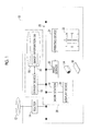
- Fig. 1 is a diagram showing the overall configuration of the print production system 10 including an image display system 38 according to the present embodiment.
- a router 14 that is a device for relaying the connection with a network 12, a server device 16 that can be accessed through the network 12 from each terminal device (not shown) belonging to an external network, a work station 18 (image display control device) that performs various kinds of information processing on the content data acquired from the server device 16 or the like, a print server 20 having a print processing function, and a printing device 24 that can form a print 22 based on the output data from the print server 20 are provided in the print production system 10.
- the server device 16 is a device that forms the core of the workflow management in the print production system 10.
- the server device 16 is communicably connected to the work station 18 and the print server 20 through a local area network (LAN) 26 built in the print production system 10.
- the server device 16 may be communicably connected to each terminal device (not shown) of a designer or a production company through the router 14 and the network 12.
- a storage device 28 that can store various kinds of data for the workflow is connected to the server device 16. For example, content data, output data (for example, plate making data, printing plate data, or calibration data), a job ticket (for example, a job definition format (JDF) file), a color profile, color sample data, and the like are stored in the storage device 28.
- content data for example, plate making data, printing plate data, or calibration data
- job ticket for example, a job definition format (JDF) file
- JDF job definition format
- a database regarding image information (hereinafter, referred to as an image information DB 30) is constructed in the storage device 28.
- the image information DB 30 is a collection of image information in units of a print job, a document, a page, or content, for example.
- the work station 18 is a device that can create page-unit data (page data) after performing pre-flight processing on content data including a character, a graphic, a picture, a photograph, and the like.
- the work station 18 performs imposition processing according to a designated binding method or paper folding method with reference to the tag information of a job ticket.
- a display device 32 that can display an arbitrary image for a variety of work is connected to the work station 18.
- the display method of the display device 32 may be not only liquid crystal, organic electro-luminescence (EL), and a cathode ray tube (CRT) but also a projector that projects an image onto the screen.
- the print server 20 performs raster image processing (RIP) on the plate making data or the like subjected to imposition processing, and supplies the obtained output data to the printing device 24.
- RIP raster image processing
- the printing device 24 outputs the print 22, in which an image is formed on a print medium 34, based on the output data supplied from the print server 20.
- Types of the print medium 34 include not only paper, such as synthetic paper, thick paper, and aluminum-evaporated paper, but also resin such as vinyl chloride and polyethylene terephthalate (PET), tarpaulin, and a metal sheet.
- a direct digital color proofing DDCP
- an ink jet color proofer a low-resolution color laser printer (electrophotographic type), an ink jet printer, and the like may be used.
- the print 22 in which an image is formed on the print medium 34 is output by depositing the ink through a printing plate 36 and an intermediate transfer member (not shown).
- the print 22 can be directly output without generating the printing plate 36.
- a digital printing press an ink jet printer, a wide format printer, an ink jet color proofer, a color laser printer, and the like may be used.
- the server device 16, the work station 18, the storage device 28, and the display device 32 form the image display system 38 that selects two or more pieces of image information 60 ( Fig. 2 ) from the image information DB 30 and performs preview display.
- Fig. 2 is an electrical block diagram of the work station 18 shown in Fig. 1 .
- the work station 18 is a computer that basically includes a control unit 50, a communication I/F 52, an input unit 54, a display I/F 56, and a memory 58 (storage medium).
- the communication I/F 52 is an interface that transmits and receives electric signals to and from an external device. Thereby, the work station 18 can acquire various kinds of data (for example, a plurality of pieces of image information 60) from the server device 16 ( Fig. 1 ).
- the input unit 54 includes various input devices, such as a mouse, a track ball, a keyboard, and a touch panel.
- the display I/F 56 is an interface for outputting a display control signal to the display device 32. Accordingly, the display device 32 can display various images including a window W1 ( Fig. 5 or the like) and a window W2 ( Fig. 6 or the like).
- the memory 58 stores a program, data, and the like required when the control unit 50 controls each component.
- a plurality of pieces of image information 60 from the image information DB 30 ( Fig. 1 ) are stored.
- the memory 58 may be a non-transitory and computer-readable storage medium.
- computer-readable storage media are storage devices, such as portable media including a magneto-optical disc, a ROM, a CD-ROM, and a flash memory and a hard disk built in a computer system.
- the storage media may hold a program dynamically for a short period of time, or may hold a program for a fixed period of time.
- the control unit 50 is configured to include an information processing device (so-called processor), such as a central processing unit (CPU).
- processor such as a central processing unit (CPU).
- the control unit 50 can realize each function including a preview image selecting section 62 and a display data creating section 64 by reading and executing a program stored in the memory 58.
- the preview image selecting section 62 selects two or more pieces of image information 60 provided for preview display according to an operation through the input unit 54.
- the preview image selecting section 62 includes an identification number granting section 66 that grants an identification number to each of a plurality of pieces of image information 60, an identification number allocation section 68 that assigns an identification number according to the scale to be described later, and a selection range determining section 70 that selects a range of the identification number.
- the display data creating section 64 creates display data provided for display of various images. Specifically, the display data creating section 64 includes a screen creating section 72, which creates a preview screen 100 ( Fig. 5 ) or the like, and a track bar creating section 74, which creates a track bar control (hereinafter, simply referred to as a "track bar").
- a screen creating section 72 which creates a preview screen 100 ( Fig. 5 ) or the like
- a track bar creating section 74 which creates a track bar control (hereinafter, simply referred to as a "track bar").
- the image display system 38 is configured as described above. Subsequently, the operation of the image display system 38 (in particular, the work station 18) shown in Fig. 1 will be described in detail primarily with reference to the flowchart of Fig. 3 .
- step S1 the identification number granting section 66 grants an identification number to each of a plurality of pieces of image information 60 registered in the image information DB 30.
- the image information 60 having a "print job" as a basic unit will be described as an example.
- Fig. 4A is a schematic explanatory diagram for an identification number granting method. For example, 1001 print jobs having print job names of "JOB0001" to "JOB1001" are registered in the image information DB 30 ( Fig. 1 ).
- the identification number granting section 66 may sort 1001 print jobs according to the arbitrary rules and grant identification numbers sequentially from 1.
- Examples of the sort key include a print job name, a customer name, a deadline, type of production, layout of the page, the number of copies to be printed, and printing conditions (item directly involved in the printing process or the metadata).
- a "print job name” is used as the sort key, and sorting in ascending order is performed.
- a minimum value (1) of identification numbers is granted to the print job "JOB0001”
- a maximum value (1001) ofidentification numbers is granted to the print job "JOB1001"
- step S2 the identification number allocation section 68 assigns the identification numbers granted in step S1 according to a predetermined linear scale.
- a scale hereinafter, referred to as a standard scale obtained by matching the full range of the identification number with the entire position is adopted.
- Fig. 4B is a schematic explanatory diagram for a method of assigning an identification number according to the standard scale.
- step S3 the work station 18 performs preview display of a plurality of pieces of image information 60 on the display device 32.
- the screen creating section 72 creates display data of the preview screen 100 ( Fig. 5 ) and then outputs the display data to the display I/F 56.
- the window W1 including the preview screen 100 is displayed on the display device 32.
- a preview column 102 which is a collection of the image information 60
- an icon group 104 which is configured to include a plurality of tool icons, are disposed on the preview screen 100.
- a predetermined number of pieces (for example, 50 pieces) of image information 60 are disposed in a two-dimensional manner.
- a preview display target is the image information 60 to which identification numbers of 1 to 50 are granted.
- the image information 60 (identification numbers 4, 5, and 9 to 50) other than the print jobs that are currently displayed can also be viewed by operating scroll bars 106 and 108.
- desired annotation information, calibration history, or the like it is possible to add desired annotation information, calibration history, or the like to the position (specifically, each piece of image information 60) of the preview column 102 according to an operation through the icon group 104.
- step S4 the control unit 50 determines whether or not to continue the preview display in step S3.
- step S4: YES the process proceeds to the next step (S5).
- step S5 the control unit 50 determines whether or not there is a call request of the window W2 ( Fig. 6 ). Specifically, this determination is performed according to whether or not a clicking operation of the input unit 54 ( Fig. 2 ) has been received in a state where a cursor 112 is located on the icon group 104 (specific icon 110).
- step S5: NO the process returns to step S3 and the control unit 50 repeats the operation of steps S3 to S5 sequentially.
- step S5 YES
- the process proceeds to the next step (S6).
- step S6 the work station 18 displays a track bar 122 ( Fig. 7A ; window W2) on the display device 32.
- the track bar creating section 74 creates display data of the track bar 122 according to the allocation result of the identification number allocation section 68.
- the screen creating section 72 creates display data of a selection screen 120 (including the track bar 122) and outputs the display data to the display I/F 56.
- the window W2 including the selection screen 120 is displayed on the display device 32.
- the window W2 is displayed so as to overlap with an approximately central position of the window W1.
- the display state of the window W1 changes to "passive".
- the preview column 102 and the icon group 104 are colored dark, and the control unit 50 temporarily disables an input operation through the window W1.
- Figs. 7A and 7B are image diagrams of the selection screen 120 shown in Fig. 6 .
- the track bar 122 for selecting the identification number, a balloon portion 124 present above the track bar 122, and an erase mark 126 for hiding the window W2 are disposed on the selection screen 120.
- the track bar 122 is configured to include a bar portion 128 having a fixed length (or a variable length) and extending in one direction (in this example shown in Figs. 7A and 7B , a horizontal direction), a rectangular slider 130 provided on the bar portion 128, and a scale number 132 present above the bar portion 128.
- the slider 130 is configured so as to be movable along the horizontal direction in a range from one end position 134 to the other end position 136 of the bar portion 128.
- the scale number 132 includes five numbers disposed at approximately equal intervals, specifically, "1", “250”, “500”, “750”, and "1001".
- a region expressing the standard scale of the image region including the track bar 122 is referred to as a standard scale region 138.
- Character information regarding the indicated range of the slider 130 is written in the balloon portion 124.
- a lower limit (1) of the indicated range and the entire print job name "JOB0001" corresponding to the lower limit and an upper limit (50) of the indicated range and a part of the print job name "JOB0050" corresponding to the upper limit are written.
- the content of the balloon portion 124 is immediately changed according to the stop position of the slider 130.
- a lower limit (251) of the indicated range and the entire print job name "JOB0251" corresponding to the lower limit and an upper limit (300) of the indicated range and a part of the print job name "JOB0300” corresponding to the upper limit are written.
- step S7 of Fig. 3 the control unit 50 determines whether or not a specific input operation has been performed. For example, this is determined according to whether or not a long pressing operation (long tap) on the slider 130 has been received. When there is an operation (step S7: YES), the process proceeds to the next step (S8).
- step S8 the identification number allocation section 68 assigns some of the identification numbers granted in step S1 again according to the different scale from the standard scale. Specifically, the identification number allocation section 68 sets a peripheral position 152 ( Fig. 8B ) when a specific input operation is received, and assigns each identification number according to the enlarged scale, which will be described later, at the peripheral position 152. Then, the work station 18 displays a new track bar 122b on the display device 32 (step S6).
- a track bar 122b is configured to include a bar portion 128, a wide slider 150, and a scale number 154 in which the value has changed at the peripheral position 152 (rectangular region surrounded by the dotted line) of the slider 150.
- the peripheral position 152 expresses a scale (hereinafter, referred to as an enlarged scale) enlarged to a predetermined magnification (here, two times) with respect to the standard scale. That is, an enlarged scale region 156 corresponds to a region, which expresses a doubly enlarged scale, of the image region including the track bar 122b.
- step S8 the work station 18 displays a new track bar 122c on the display device 32 (step S6).
- the track bar 122c is configured to include a bar portion 128, a wider slider 160, and a scale number 154 in which the value has changed at the peripheral position 162 (rectangular region surrounded by the dotted line) of the slider 160.
- the peripheral position 162 (a part of the bar portion 128) expresses an enlarged scale that is 4 times the standard scale. That is, an enlarged scale region 166 corresponds to a region, which expresses a fourfold enlarged scale, of the image region including the track bar 122c.
- Fig. 9 is a schematic diagram showing the determination result of the scale in the display forms shown in Figs. 8A to 8C .
- a bar graph 171 shows the scale in the display form shown in Fig. 8A .
- the full range shown by the graph that is, the full range of identification numbers of 1 to 1001, is the standard scale (area without filling).
- a bar graph 172 shows the scale in the display form shown in Fig. 8B .
- a range of identification numbers of 1 to 175 and 376 to 1001 of the full range shown by the graph is the standard scale.
- the range of the enlarged scale region 156 ( Fig. 8B ), that is, the range of identification numbers of 176 to 376, is a doubly enlarged scale (area of single hatching).
- the residual range is an object that is not to be displayed (area with filling).
- a bar graph 173 shows the scale in the display form shown in Fig. 8C .
- a range of identification numbers of 1 to 175 and 376 to 1001 of the full range shown by the graph is the standard scale.
- the range of the enlarged scale region 166 ( Fig. 8C ), that is, the range of identification numbers of 226 to 326, is a fourfold enlarged scale (area of double hatching).
- the residual range is an object that is not to be displayed (area with filling).
- the designated range can be changed according to the scale extended twice and 4 times by moving the wide sliders 150 and 160 located at the peripheral position 152 and 162 in the horizontal direction. In other words, the operator can finely adjust the designated range.
- the track bar creating section 74 may create display data by changing the width of each of the sliders 140, 150, and 160 according to the number of possible displays of the image information 60 (in the example shown in Fig. 5 , 50 fixed values). The operator can check the designated range of the identification number at a glance based on the size of the width. In relation to this, the track bar creating section 74 may perform adjustment so as not to be less than the threshold value when changing the width of the slider 130 or the like. Thus, it is possible to prevent a situation where it becomes difficult to hold the slider 130 or the like.
- the track bar creating section 74 may create display data by making the display form at the peripheral positions 152 and 162 different from the display form at the residual position.
- a display form to emphasize the peripheral positions 152 and 162 for example, to relatively increase the brightness and saturation or to give visual effects to call attention
- the operator can check the change of the scale at a glance based on the difference in the display form.
- control unit 50 may perform control to end the display on the enlarged scale and return to the display form shown in Fig. 7B .
- an operation of moving the slider 150 or 160 away from the peripheral position 152 or 162 and an operation of moving the cursor 112 to the outside of the window W2 can be mentioned.
- step S7 of Fig. 3 when there is no specific input operation (long pressing operation on the slider 130) (step S7: NO), the control unit 50 determines whether or not there has been any operation to end the selection in step S9. For example, this is determined according to whether or not a clicking operation on the erase mark 126 ( Figs. 7A to 8C ) has been received. When there is no operation (step S9: NO), the process returns to step S6 and the control unit 50 repeats the operation of steps S6 to S9 sequentially.
- step S9 when there is an operation (step S9: YES), the process proceeds to the next step (S10).
- the window W2 is not displayed, and the display state of the window W1 returns to "active" .
- the selection range determining section 70 determines the selection range of the identification number from the instruction position of the slider 130 or the like. Specifically, the selection range determining section 70 calculates the range (minimum and maximum values) of the identification number based on the position corresponding to the number of pixels of the slider 130 or the like and the correspondence relationship shown in Fig. 4B . In all of the examples shown in Figs. 8A to 8C , the range of identification numbers of 251 to 300 is determined as a selection range.
- step S3 the process returns to step S3, and the work station 18 performs preview display of a plurality of pieces of image information 60, to which the identification numbers within the selection range determined in step S10 are granted, on the display device 32.
- An object to be displayed in the preview column 102 ( Fig. 5 ) is the image information 60 to which identification numbers of 251 to 300 are granted.
- step S4 the process returns to step S4 of Fig. 3 , and the image display system 38 ends the operation regarding the preview display when the preview display is not continued (step S4: NO).
- the work station 18 as an image display control device selects two or more pieces of image information 60 from a plurality of pieces of image information 60 (image information DB 30), to which identification numbers are granted, and performs preview display on the display device 32.
- the work station 18 includes: the track bar creating section 74 that creates display data of the track bar 122 (the same as 122a to 122c) including the bar portion 128 with a fixed length and the slider 130 (the same as the sliders 140, 150, and 160) that is freely movable along the extending direction of the bar portion 128; the identification number allocation section 68 that assigns each of the identification numbers according to the standard scale; and the selection range determining section 70 that determines the selection range of the identification number from the instruction position of the slider 130 (the same as in the sliders 140, 150, and 160) of the track bar 122 (the same as in 122a to 122c) displayed based on the display data.
- the identification number allocation section 68 assigns each identification number according to the enlarged scale that is larger than the standard scale, instead of the standard scale, at the peripheral positions 152 and 162 of the sliders 150 and 160.
- the image display system 38 includes the storage device 28 that can store a plurality of pieces of image information 60 and the display device 32 that performs preview display of two or more selected pieces of image information 60.
- the forms of the track bars 122a to 122c are not limited to the examples shown in Fig. 7A and the like, and any configuration can be adopted as long as the range (lower and upper limits) of the identification number can be specified.
- applications of the image information 60 are not limited to the production of the print 22, and may be production, viewing, and the like of various produced materials (electronic data, distribution service by streaming, and the like) provided for e-commerce.
Abstract
Description
- The present invention relates to an image display control device, an image display control method, an image display control program, and an image display system to select two or more pieces of image information from a plurality of pieces of image information to which identification numbers are granted and to perform preview display of the selected image information on a display device.
- Various techniques for selecting necessary image information from a plurality of pieces of image information stored in advance and performing preview display of the content have been proposed.
- A method of changing the display target page of the finished image according to an instruction operation on the guide scale image has been proposed in
JP2007-110677A Fig. 6 , and the like). In addition,JP2007-110677A - A method of selecting an electronic document and the page through the bar control, which is a collection of a plurality of markers, has been proposed in
US7100119B (Figs. 5 and6B and the like). In addition,U.S. Pat. No. 7100119 describes that the width of the designated marker is made to be relatively great. - Incidentally, if the amount of image information to be searched for is increased, the time for selecting the desired image information is increased accordingly. In the methods proposed in
JP2007-110677A US7100119B , however, it is difficult to finely adjust the current search position while checking the total amount of image information. As a result, there has been a problem in that a long time is required until desired image information is found and selected. - The invention has been made to solve the aforementioned problem, and it is an object of the invention to provide an image display control device, an image display control method, an image display control program, and an image display system that can efficiently select desired image information without spending a lot of time even if the amount of image information to be searched for is significantly large.
- According to an aspect of the invention, there is provided an image display control device that selects two or more pieces of image information from a plurality of pieces of image information to which identification numbers are granted and performs preview display on a display device. The image display control device includes: a track bar creating section that creates display data of a track bar having a bar portion with a fixed length and a slider that is freely movable along an extending direction of the bar portion; an identification number allocation section that assigns each of the identification numbers according to a standard scale obtained by matching a full range of the identification number with an entire position of the bar portion; and a selection range determining section that determines a selection range of the identification number, which is assigned by the identification number allocation section, from an instruction position of the slider of the track bar displayed based on the display data created by the track bar creating section. The identification number allocation section assigns each of the identification numbers according to an enlarged scale, which is larger than the standard scale, at a peripheral position of the slider.
- Thus, in the standard scale obtained by matching the full range of the identification number with the entire position of the bar portion of the track bar, at the peripheral position of the slider, each identification number is assigned according to the enlarged scale that is larger than the standard scale. Accordingly, it is possible to adjust the current search position finely in the enlarged scale region while checking the total amount of image information in the standard scale region. As a result, even if the amount of image information to be searched for is significantly large, it is possible to efficiently select the desired image information without spending a lot of time.
- Preferably, the identification number allocation section sets the peripheral position when a specific input operation is received and assigns each of the identification numbers according to the enlarged scale at the peripheral position.
- Preferably, the identification number allocation section assigns each of the identification numbers according to the standard scale when the slider is moved away from the peripheral position.
- Preferably, the track bar creating section creates the display data by changing a width of the slider according to the number of possible displays of the image information.
- Preferably, the track bar creating section creates the track bar in which a display form at the peripheral position is different from a display form at a residual position.
- According to another aspect of the invention, there is provided an image display control method of selecting two or more pieces of image information from a plurality of pieces of image information to which identification numbers are granted and performing preview display on a display device. The image display control method causes a computer to execute: a creation step of creating display data of a track bar having a bar portion with a fixed length and a slider that is freely movable along an extending direction of the bar portion; an allocation step of assigning each of the identification numbers according to a standard scale obtained by matching a full range of the identification number with an entire position of the bar portion; and a determination step of determining a selection range of the assigned identification number from an instruction position of the slider of the track bar displayed based on the created display data. In the allocation step, each of the identification numbers is assigned according to an enlarged scale, which is larger than the standard scale, at a peripheral position of the slider.
- According to still another aspect of the invention, there is provided an image display control program for selecting two or more pieces of image information from a plurality of pieces of image information to which identification numbers are granted and for performing preview display on a display device. The image display control program causes a computer to execute: a creation step of creating display data of a track bar having a bar portion with a fixed length and a slider that is freely movable along an extending direction of the bar portion; an allocation step of assigning each of the identification numbers according to a standard scale obtained by matching a full range of the identification number with an entire position of the bar portion; and a determination step of determining a selection range of the assigned identification number from an instruction position of the slider of the track bar displayed based on the created display data. In the allocation step, each of the identification numbers is assigned according to an enlarged scale, which is larger than the standard scale, at a peripheral position of the slider.
- According to still another aspect of the invention, there is provided an image display system including: the image display control device described above; a storage device that stores a plurality of pieces of image information; and a display device that performs preview display of two or more pieces of image information that are selected from the plurality of pieces of image information stored in the storage device by the image display control device.
- According to the image display control device, the image display control method, the image display control program, and the image display system according to the aspects of the invention, at the peripheral position of the slider in the standard scale obtained by matching the full range of the identification number with the entire position of the bar portion of the track bar, each identification number is assigned according to the enlarged scale that is larger than the standard scale. Accordingly, it is possible to adjust the current search position finely in the enlarged scale region while checking the total amount of image information in the standard scale region. As a result, even if the amount of image information to be searched for is significantly large, it is possible to efficiently select the desired image information without spending a lot of time.
-
-
Fig. 1 is a diagram showing the overall configuration of a print production system including an image display system according to an embodiment of the invention. -
Fig. 2 is an electrical block diagram of a work station shown inFig. 1 . -
Fig. 3 is a flowchart provided to explain the operation of the image display system shown inFig. 1 . -
Fig. 4A is a schematic explanatory diagram for an identification number granting method. -
Fig. 4B is a schematic explanatory diagram for a method of assigning an identification number according to the standard scale. -
Fig. 5 is a first image diagram showing a preview screen of image information. -
Fig. 6 is a second image diagram showing a preview screen of image information. -
Figs. 7A and 7B are image diagrams showing a selection screen inFig. 6 . -
Figs. 8A to 8C are image diagrams showing a temporal change of the selection screen when a specific input operation is executed. -
Fig. 9 is a schematic diagram showing the determination result of the scale in the display forms shown inFigs. 8A to 8C . - Hereinafter, for an image display control method according to the invention, an appropriate embodiment in the relationship with an image display control device, an image display control program, and an image display system to implement the image display control method will be described in detail with reference to the accompanying diagrams.
-
Fig. 1 is a diagram showing the overall configuration of theprint production system 10 including animage display system 38 according to the present embodiment. - A
router 14 that is a device for relaying the connection with anetwork 12, aserver device 16 that can be accessed through thenetwork 12 from each terminal device (not shown) belonging to an external network, a work station 18 (image display control device) that performs various kinds of information processing on the content data acquired from theserver device 16 or the like, aprint server 20 having a print processing function, and aprinting device 24 that can form aprint 22 based on the output data from theprint server 20 are provided in theprint production system 10. - The
server device 16 is a device that forms the core of the workflow management in theprint production system 10. Theserver device 16 is communicably connected to thework station 18 and theprint server 20 through a local area network (LAN) 26 built in theprint production system 10. Theserver device 16 may be communicably connected to each terminal device (not shown) of a designer or a production company through therouter 14 and thenetwork 12. - A
storage device 28 that can store various kinds of data for the workflow is connected to theserver device 16. For example, content data, output data (for example, plate making data, printing plate data, or calibration data), a job ticket (for example, a job definition format (JDF) file), a color profile, color sample data, and the like are stored in thestorage device 28. - In the example shown in
Fig. 1 , a database regarding image information (hereinafter, referred to as an image information DB 30) is constructed in thestorage device 28. The image information DB 30 is a collection of image information in units of a print job, a document, a page, or content, for example. - The
work station 18 is a device that can create page-unit data (page data) after performing pre-flight processing on content data including a character, a graphic, a picture, a photograph, and the like. Thework station 18 performs imposition processing according to a designated binding method or paper folding method with reference to the tag information of a job ticket. - A
display device 32 that can display an arbitrary image for a variety of work is connected to thework station 18. The display method of thedisplay device 32 may be not only liquid crystal, organic electro-luminescence (EL), and a cathode ray tube (CRT) but also a projector that projects an image onto the screen. - The
print server 20 performs raster image processing (RIP) on the plate making data or the like subjected to imposition processing, and supplies the obtained output data to theprinting device 24. - The
printing device 24 outputs theprint 22, in which an image is formed on aprint medium 34, based on the output data supplied from theprint server 20. Types of theprint medium 34 include not only paper, such as synthetic paper, thick paper, and aluminum-evaporated paper, but also resin such as vinyl chloride and polyethylene terephthalate (PET), tarpaulin, and a metal sheet. - When the
printing device 24 is a proof press, a direct digital color proofing (DDCP), an ink jet color proofer, a low-resolution color laser printer (electrophotographic type), an ink jet printer, and the like may be used. - When a
printing device 24 is a relief printing press, theprint 22 in which an image is formed on theprint medium 34 is output by depositing the ink through aprinting plate 36 and an intermediate transfer member (not shown). - When the
printing device 24 is a digital printing press, theprint 22 can be directly output without generating theprinting plate 36. As a digital printing press, an ink jet printer, a wide format printer, an ink jet color proofer, a color laser printer, and the like may be used. - The
server device 16, thework station 18, thestorage device 28, and thedisplay device 32 form theimage display system 38 that selects two or more pieces of image information 60 (Fig. 2 ) from theimage information DB 30 and performs preview display. -
Fig. 2 is an electrical block diagram of thework station 18 shown inFig. 1 . Thework station 18 is a computer that basically includes acontrol unit 50, a communication I/F 52, aninput unit 54, a display I/F 56, and a memory 58 (storage medium). - The communication I/
F 52 is an interface that transmits and receives electric signals to and from an external device. Thereby, thework station 18 can acquire various kinds of data (for example, a plurality of pieces of image information 60) from the server device 16 (Fig. 1 ). - The
input unit 54 includes various input devices, such as a mouse, a track ball, a keyboard, and a touch panel. The display I/F 56 is an interface for outputting a display control signal to thedisplay device 32. Accordingly, thedisplay device 32 can display various images including a window W1 (Fig. 5 or the like) and a window W2 (Fig. 6 or the like). - The
memory 58 stores a program, data, and the like required when thecontrol unit 50 controls each component. In this example shown inFig. 2 , a plurality of pieces ofimage information 60 from the image information DB 30 (Fig. 1 ) are stored. - The
memory 58 may be a non-transitory and computer-readable storage medium. Here, computer-readable storage media are storage devices, such as portable media including a magneto-optical disc, a ROM, a CD-ROM, and a flash memory and a hard disk built in a computer system. The storage media may hold a program dynamically for a short period of time, or may hold a program for a fixed period of time. - The
control unit 50 is configured to include an information processing device (so-called processor), such as a central processing unit (CPU). Thecontrol unit 50 can realize each function including a previewimage selecting section 62 and a displaydata creating section 64 by reading and executing a program stored in thememory 58. - The preview
image selecting section 62 selects two or more pieces ofimage information 60 provided for preview display according to an operation through theinput unit 54. Specifically, the previewimage selecting section 62 includes an identificationnumber granting section 66 that grants an identification number to each of a plurality of pieces ofimage information 60, an identificationnumber allocation section 68 that assigns an identification number according to the scale to be described later, and a selectionrange determining section 70 that selects a range of the identification number. - The display
data creating section 64 creates display data provided for display of various images. Specifically, the displaydata creating section 64 includes ascreen creating section 72, which creates a preview screen 100 (Fig. 5 ) or the like, and a trackbar creating section 74, which creates a track bar control (hereinafter, simply referred to as a "track bar"). - The
image display system 38 according to the present embodiment is configured as described above. Subsequently, the operation of the image display system 38 (in particular, the work station 18) shown inFig. 1 will be described in detail primarily with reference to the flowchart ofFig. 3 . - In step S1, the identification
number granting section 66 grants an identification number to each of a plurality of pieces ofimage information 60 registered in theimage information DB 30. Hereinafter, theimage information 60 having a "print job" as a basic unit will be described as an example. -
Fig. 4A is a schematic explanatory diagram for an identification number granting method. For example, 1001 print jobs having print job names of "JOB0001" to "JOB1001" are registered in the image information DB 30 (Fig. 1 ). - Here, the identification
number granting section 66 may sort 1001 print jobs according to the arbitrary rules and grant identification numbers sequentially from 1. Examples of the sort key include a print job name, a customer name, a deadline, type of production, layout of the page, the number of copies to be printed, and printing conditions (item directly involved in the printing process or the metadata). In the example shown inFig. 4A , a "print job name" is used as the sort key, and sorting in ascending order is performed. As a result, a minimum value (1) of identification numbers is granted to the print job "JOB0001", and a maximum value (1001) ofidentification numbers is granted to the print job "JOB1001" - In step S2, the identification
number allocation section 68 assigns the identification numbers granted in step S1 according to a predetermined linear scale. Here, a scale (hereinafter, referred to as a standard scale) obtained by matching the full range of the identification number with the entire position is adopted. -
Fig. 4B is a schematic explanatory diagram for a method of assigning an identification number according to the standard scale. When the position on the scale is normalized in [0, 1], the identificationnumber allocation section 68 assigns a position "0" to theidentification number 1 and assigns a position "1" to theidentification number 1001. That is, when described in a general formula, a position "(k-1)/1000" is assigned to an identification number k (k = 1 to 1001). - Similarly, when the position is converted into a position [0, Np] (unit is the number of pixels) on the image, the identification
number allocation section 68 assigns the position "0" (pixel) to theidentification number 1 and assigns a position "Np" (pixel) to theidentification number 1001. That is, when described in a general formula, a position "(k-1)Np/1000" (pixel) is assigned to the identification number k (k = 1 to 1001). - In step S3, the
work station 18 performs preview display of a plurality of pieces ofimage information 60 on thedisplay device 32. In response to an instruction to start the display, thescreen creating section 72 creates display data of the preview screen 100 (Fig. 5 ) and then outputs the display data to the display I/F 56. As a result, the window W1 including thepreview screen 100 is displayed on thedisplay device 32. - As shown in
Fig. 5 , apreview column 102, which is a collection of theimage information 60, and anicon group 104, which is configured to include a plurality of tool icons, are disposed on thepreview screen 100. - In the
preview column 102, a predetermined number of pieces (for example, 50 pieces) ofimage information 60 are disposed in a two-dimensional manner. In the initial setting, a preview display target is theimage information 60 to which identification numbers of 1 to 50 are granted. The image information 60 (identification numbers 4, 5, and 9 to 50) other than the print jobs that are currently displayed can also be viewed by operatingscroll bars preview column 102 according to an operation through theicon group 104. - In step S4, the
control unit 50 determines whether or not to continue the preview display in step S3. When the preview display continues (step S4: YES), the process proceeds to the next step (S5). - In step S5, the
control unit 50 determines whether or not there is a call request of the window W2 (Fig. 6 ). Specifically, this determination is performed according to whether or not a clicking operation of the input unit 54 (Fig. 2 ) has been received in a state where acursor 112 is located on the icon group 104 (specific icon 110). When there is no request (step S5: NO), the process returns to step S3 and thecontrol unit 50 repeats the operation of steps S3 to S5 sequentially. In contrast, when there is a request (step S5: YES), the process proceeds to the next step (S6). - In step S6, the
work station 18 displays a track bar 122 (Fig. 7A ; window W2) on thedisplay device 32. Prior to this display, the trackbar creating section 74 creates display data of thetrack bar 122 according to the allocation result of the identificationnumber allocation section 68. Then, thescreen creating section 72 creates display data of a selection screen 120 (including the track bar 122) and outputs the display data to the display I/F 56. As a result, the window W2 including theselection screen 120 is displayed on thedisplay device 32. - As shown in
Fig. 6 , the window W2 is displayed so as to overlap with an approximately central position of the window W1. In a state where the window W2 is displayed, the display state of the window W1 changes to "passive". In this example shown inFig. 6 , thepreview column 102 and theicon group 104 are colored dark, and thecontrol unit 50 temporarily disables an input operation through the window W1. -
Figs. 7A and 7B are image diagrams of theselection screen 120 shown inFig. 6 . Thetrack bar 122 for selecting the identification number, aballoon portion 124 present above thetrack bar 122, and an erasemark 126 for hiding the window W2 are disposed on theselection screen 120. - The
track bar 122 is configured to include abar portion 128 having a fixed length (or a variable length) and extending in one direction (in this example shown inFigs. 7A and 7B , a horizontal direction), arectangular slider 130 provided on thebar portion 128, and ascale number 132 present above thebar portion 128. - The
slider 130 is configured so as to be movable along the horizontal direction in a range from oneend position 134 to theother end position 136 of thebar portion 128. Thescale number 132 includes five numbers disposed at approximately equal intervals, specifically, "1", "250", "500", "750", and "1001". - "1" corresponding to the minimum value of identification numbers is written at the one
end position 134 of thebar portion 128. "1001" corresponding to the maximum value of identification numbers is written at theother end position 136 of thebar portion 128. In other words, theentire bar portion 128 expresses a standard scale that linearly assigns the full range of the identification number. Hereinafter, a region expressing the standard scale of the image region including thetrack bar 122 is referred to as astandard scale region 138. - Character information regarding the indicated range of the
slider 130 is written in theballoon portion 124. In the example shown inFig. 7A , a lower limit (1) of the indicated range and the entire print job name "JOB0001" corresponding to the lower limit and an upper limit (50) of the indicated range and a part of the print job name "JOB0050" corresponding to the upper limit are written. - As shown in
Fig. 7A , when a drag operation along the direction indicated by the arrow A is performed in a state where thecursor 112 is located at the position of theslider 130, theslider 130 and theballoon portion 124 are moved in the direction indicated by the arrow A so as to follow thecursor 112. Then, when a drop operation is performed, the movement of theslider 130 and theballoon portion 124 is stopped. - In this case, the content of the
balloon portion 124 is immediately changed according to the stop position of theslider 130. In the example shown inFig. 7B , a lower limit (251) of the indicated range and the entire print job name "JOB0251" corresponding to the lower limit and an upper limit (300) of the indicated range and a part of the print job name "JOB0300" corresponding to the upper limit are written. - In step S7 of
Fig. 3 , thecontrol unit 50 determines whether or not a specific input operation has been performed. For example, this is determined according to whether or not a long pressing operation (long tap) on theslider 130 has been received. When there is an operation (step S7: YES), the process proceeds to the next step (S8). - When a long pressing operation on the
slider 130 is performed, the outline of aslider 140 in atrack bar 122a is highlighted as shown inFig. 8A . Then, when the long pressing operation is continued further, the display form of thetrack bar 122a is changed. - In step S8, the identification
number allocation section 68 assigns some of the identification numbers granted in step S1 again according to the different scale from the standard scale. Specifically, the identificationnumber allocation section 68 sets a peripheral position 152 (Fig. 8B ) when a specific input operation is received, and assigns each identification number according to the enlarged scale, which will be described later, at theperipheral position 152. Then, thework station 18 displays anew track bar 122b on the display device 32 (step S6). - As shown in
Fig. 8B , atrack bar 122b is configured to include abar portion 128, awide slider 150, and ascale number 154 in which the value has changed at the peripheral position 152 (rectangular region surrounded by the dotted line) of theslider 150. As can be understood fromFig. 8B , the peripheral position 152 (a part of the bar portion 128) expresses a scale (hereinafter, referred to as an enlarged scale) enlarged to a predetermined magnification (here, two times) with respect to the standard scale. That is, anenlarged scale region 156 corresponds to a region, which expresses a doubly enlarged scale, of the image region including thetrack bar 122b. - Then, when the long pressing operation on the
slider 150 is continued further, the display form of thetrack bar 122b is changed. Through the allocation processing (step S8) performed again by the identificationnumber allocation section 68, thework station 18 displays anew track bar 122c on the display device 32 (step S6). - As shown in
Fig. 8C , thetrack bar 122c is configured to include abar portion 128, awider slider 160, and ascale number 154 in which the value has changed at the peripheral position 162 (rectangular region surrounded by the dotted line) of theslider 160. As can be understood fromFig. 8C , the peripheral position 162 (a part of the bar portion 128) expresses an enlarged scale that is 4 times the standard scale. That is, anenlarged scale region 166 corresponds to a region, which expresses a fourfold enlarged scale, of the image region including thetrack bar 122c. -
Fig. 9 is a schematic diagram showing the determination result of the scale in the display forms shown inFigs. 8A to 8C . - A
bar graph 171 shows the scale in the display form shown inFig. 8A . The full range shown by the graph, that is, the full range of identification numbers of 1 to 1001, is the standard scale (area without filling). - A
bar graph 172 shows the scale in the display form shown inFig. 8B . A range of identification numbers of 1 to 175 and 376 to 1001 of the full range shown by the graph is the standard scale. The range of the enlarged scale region 156 (Fig. 8B ), that is, the range of identification numbers of 176 to 376, is a doubly enlarged scale (area of single hatching). The residual range is an object that is not to be displayed (area with filling). - A
bar graph 173 shows the scale in the display form shown inFig. 8C . A range of identification numbers of 1 to 175 and 376 to 1001 of the full range shown by the graph is the standard scale. The range of the enlarged scale region 166 (Fig. 8C ), that is, the range of identification numbers of 226 to 326, is a fourfold enlarged scale (area of double hatching). The residual range is an object that is not to be displayed (area with filling). - Incidentally, in
Figs. 8B and 8C , the designated range can be changed according to the scale extended twice and 4 times by moving thewide sliders peripheral position - The track
bar creating section 74 may create display data by changing the width of each of thesliders Fig. 5 , 50 fixed values). The operator can check the designated range of the identification number at a glance based on the size of the width. In relation to this, the trackbar creating section 74 may perform adjustment so as not to be less than the threshold value when changing the width of theslider 130 or the like. Thus, it is possible to prevent a situation where it becomes difficult to hold theslider 130 or the like. - In addition, the track
bar creating section 74 may create display data by making the display form at theperipheral positions peripheral positions 152 and 162 (for example, to relatively increase the brightness and saturation or to give visual effects to call attention) can be mentioned. Thus, the operator can check the change of the scale at a glance based on the difference in the display form. - When another operation is received, the
control unit 50 may perform control to end the display on the enlarged scale and return to the display form shown inFig. 7B . As examples of "another operation", an operation of moving theslider peripheral position cursor 112 to the outside of the window W2 can be mentioned. - Returning to step S7 of
Fig. 3 , when there is no specific input operation (long pressing operation on the slider 130) (step S7: NO), thecontrol unit 50 determines whether or not there has been any operation to end the selection in step S9. For example, this is determined according to whether or not a clicking operation on the erase mark 126 (Figs. 7A to 8C ) has been received. When there is no operation (step S9: NO), the process returns to step S6 and thecontrol unit 50 repeats the operation of steps S6 to S9 sequentially. - In contrast, when there is an operation (step S9: YES), the process proceeds to the next step (S10). In this case, according to the clicking operation on the erase mark 126 (
Fig. 7A or the like), the window W2 is not displayed, and the display state of the window W1 returns to "active" . - In step S10, the selection
range determining section 70 determines the selection range of the identification number from the instruction position of theslider 130 or the like. Specifically, the selectionrange determining section 70 calculates the range (minimum and maximum values) of the identification number based on the position corresponding to the number of pixels of theslider 130 or the like and the correspondence relationship shown inFig. 4B . In all of the examples shown inFigs. 8A to 8C , the range of identification numbers of 251 to 300 is determined as a selection range. - Then, the process returns to step S3, and the
work station 18 performs preview display of a plurality of pieces ofimage information 60, to which the identification numbers within the selection range determined in step S10 are granted, on thedisplay device 32. An object to be displayed in the preview column 102 (Fig. 5 ) is theimage information 60 to which identification numbers of 251 to 300 are granted. - Then, the process returns to step S4 of
Fig. 3 , and theimage display system 38 ends the operation regarding the preview display when the preview display is not continued (step S4: NO). - As described above, the
work station 18 as an image display control device selects two or more pieces ofimage information 60 from a plurality of pieces of image information 60 (image information DB 30), to which identification numbers are granted, and performs preview display on thedisplay device 32. - The
work station 18 includes: the trackbar creating section 74 that creates display data of the track bar 122 (the same as 122a to 122c) including thebar portion 128 with a fixed length and the slider 130 (the same as thesliders bar portion 128; the identificationnumber allocation section 68 that assigns each of the identification numbers according to the standard scale; and the selectionrange determining section 70 that determines the selection range of the identification number from the instruction position of the slider 130 (the same as in thesliders number allocation section 68 assigns each identification number according to the enlarged scale that is larger than the standard scale, instead of the standard scale, at theperipheral positions sliders - In addition to the
work station 18 described above, theimage display system 38 includes thestorage device 28 that can store a plurality of pieces ofimage information 60 and thedisplay device 32 that performs preview display of two or more selected pieces ofimage information 60. - By adopting such a configuration, it is possible to finely adjust the current search position in the
enlarged scale regions standard scale region 138. Therefore, even if the amount ofimage information 60 to be searched for is significantly large, it is possible to efficiently select the desiredimage information 60 without spending a lot of time. - This invention is not limited to the embodiment described above, and various changes can be freely made without deviating from the subject matter of this invention.
- For example, the forms of the
track bars 122a to 122c are not limited to the examples shown inFig. 7A and the like, and any configuration can be adopted as long as the range (lower and upper limits) of the identification number can be specified. - In addition, applications of the
image information 60 are not limited to the production of theprint 22, and may be production, viewing, and the like of various produced materials (electronic data, distribution service by streaming, and the like) provided for e-commerce.
Claims (8)
- An image display control device that selects two or more pieces of image information from a plurality of pieces of image information to which identification numbers are granted and performs preview display on a display device, the device comprising:a track bar creating section that creates display data of a track bar having a bar portion with a fixed length and a slider that is freely movable along an extending direction of the bar portion;an identification number allocation section that assigns each of the identification numbers according to a standard scale obtained by matching a full range of the identification number with an entire position of the bar portion; anda selection range determining section that determines a selection range of the identification number, which is assigned by the identification number allocation section, from an instruction position of the slider of the track bar displayed based on the display data created by the track bar creating section,wherein the identification number allocation section assigns each of the identification numbers according to an enlarged scale, which is larger than the standard scale, at a peripheral position of the slider.
- The image display control device according to claim 1,
wherein the identification number allocation section sets the peripheral position when a specific input operation is received, and assigns each of the identification numbers according to the enlarged scale at the peripheral position. - The image display control device according to claim 2,
wherein the identification number allocation section assigns each of the identification numbers according to the standard scale when the slider is moved away from the peripheral position. - The image display control device according to any one of claims 1 to 3,
wherein the track bar creating section creates the display data by changing a width of the slider according to the number of possible displays of the image information. - The image display control device according to any one of claims 1 to 4,
wherein the track bar creating section creates the track bar in which a display form at the peripheral position is different from a display form at a residual position. - An image display control method of selecting two or more pieces of image information from a plurality of pieces of image information to which identification numbers are granted and performing preview display on a display device, the method causing a computer to execute:a creation step of creating display data of a track bar having a bar portion with a fixed length and a slider that is freely movable along an extending direction of the bar portion;an allocation step of assigning each of the identification numbers according to a standard scale obtained by matching a full range of the identification number with an entire position of the bar portion; anda determination step of determining a selection range of the assigned identification number from an instruction position of the slider of the track bar displayed based on the created display data,wherein, in the allocation step, each of the identification numbers is assigned according to an enlarged scale, which is larger than the standard scale, at a peripheral position of the slider.
- An image display control program for selecting two or more pieces of image information from a plurality of pieces of image information to which identification numbers are granted and for performing preview display on a display device, the program causing a computer to execute:a creation step of creating display data of a track bar having a bar portion with a fixed length and a slider that is freely movable along an extending direction of the bar portion;an allocation step of assigning each of the identification numbers according to a standard scale obtained by matching a full range of the identification number with an entire position of the bar portion; anda determination step of determining a selection range of the assigned identification number from an instruction position of the slider of the track bar displayed based on the created display data,wherein, in the allocation step, each of the identification numbers is assigned according to an enlarged scale, which is larger than the standard scale, at a peripheral position of the slider.
- An image display system, comprising:the image display control device according to any one of claims 1 to 5;a storage device that stores a plurality of pieces of image information; anda display device that performs preview display of two or more pieces of image information that are selected from the plurality of pieces of image information stored in the storage device by the image display control device.
Applications Claiming Priority (1)
| Application Number | Priority Date | Filing Date | Title |
|---|---|---|---|
| JP2013181757A JP5893594B2 (en) | 2013-09-03 | 2013-09-03 | Image display control apparatus, method, program, and image display system |
Publications (1)
| Publication Number | Publication Date |
|---|---|
| EP2843530A1 true EP2843530A1 (en) | 2015-03-04 |
Family
ID=51454554
Family Applications (1)
| Application Number | Title | Priority Date | Filing Date |
|---|---|---|---|
| EP14182319.5A Withdrawn EP2843530A1 (en) | 2013-09-03 | 2014-08-26 | Image display control device, image display control method, image display control program, and image display system |
Country Status (3)
| Country | Link |
|---|---|
| US (1) | US20150062641A1 (en) |
| EP (1) | EP2843530A1 (en) |
| JP (1) | JP5893594B2 (en) |
Cited By (10)
| Publication number | Priority date | Publication date | Assignee | Title |
|---|---|---|---|---|
| CN111459375A (en) * | 2020-03-31 | 2020-07-28 | 北京金山安全软件有限公司 | Page sliding position control method and device, electronic equipment and storage medium |
| US11641517B2 (en) | 2016-06-12 | 2023-05-02 | Apple Inc. | User interface for camera effects |
| US11669985B2 (en) | 2018-09-28 | 2023-06-06 | Apple Inc. | Displaying and editing images with depth information |
| US11687224B2 (en) | 2017-06-04 | 2023-06-27 | Apple Inc. | User interface camera effects |
| US11706521B2 (en) | 2019-05-06 | 2023-07-18 | Apple Inc. | User interfaces for capturing and managing visual media |
| US11711614B2 (en) | 2015-04-23 | 2023-07-25 | Apple Inc. | Digital viewfinder user interface for multiple cameras |
| US11722764B2 (en) | 2018-05-07 | 2023-08-08 | Apple Inc. | Creative camera |
| US11770601B2 (en) | 2019-05-06 | 2023-09-26 | Apple Inc. | User interfaces for capturing and managing visual media |
| US11778339B2 (en) | 2021-04-30 | 2023-10-03 | Apple Inc. | User interfaces for altering visual media |
| US11895391B2 (en) | 2018-09-28 | 2024-02-06 | Apple Inc. | Capturing and displaying images with multiple focal planes |
Families Citing this family (4)
| Publication number | Priority date | Publication date | Assignee | Title |
|---|---|---|---|---|
| JP6808550B2 (en) * | 2017-03-17 | 2021-01-06 | キヤノン株式会社 | Information processing equipment, information processing methods and programs |
| KR102536267B1 (en) | 2017-12-26 | 2023-05-25 | 삼성전자주식회사 | Electronic device and method for displaying slider track and slider |
| JP7279622B2 (en) * | 2019-11-22 | 2023-05-23 | トヨタ自動車株式会社 | display device and display program |
| CN114860138A (en) * | 2022-04-28 | 2022-08-05 | 北京亦心科技有限公司 | Image display method, image display device, electronic device, and storage medium |
Citations (7)
| Publication number | Priority date | Publication date | Assignee | Title |
|---|---|---|---|---|
| US20020063737A1 (en) * | 2000-11-30 | 2002-05-30 | Ephraim Feig | Zoom-capable scrollbar |
| US7100119B2 (en) | 2002-11-01 | 2006-08-29 | Microsoft Corporation | Page bar control |
| US20070058210A1 (en) * | 2005-09-14 | 2007-03-15 | Yoshifumi Sakuramata | Image processing apparatus and computer program product |
| US20090282362A1 (en) * | 2008-05-07 | 2009-11-12 | Hoya Corporation | Graphic system displaying scroll bar |
| JP2012044474A (en) * | 2010-08-19 | 2012-03-01 | Nec Personal Computers Ltd | Information processing device, information processing method and program |
| EP2530676A2 (en) * | 2011-05-31 | 2012-12-05 | Samsung Electronics Co., Ltd. | Timeline-based content control method and apparatus using dynamic distortion of timeline bar, and method and apparatus for controlling video and audio clips using the same |
| EP2530677A2 (en) * | 2011-05-31 | 2012-12-05 | Samsung Electronics Co., Ltd. | Method and apparatus for controlling a display of multimedia content using a timeline-based interface |
Family Cites Families (1)
| Publication number | Priority date | Publication date | Assignee | Title |
|---|---|---|---|---|
| JP2006018749A (en) * | 2004-07-05 | 2006-01-19 | Canon Inc | Information processor, data display method, program, and recording medium |
-
2013
- 2013-09-03 JP JP2013181757A patent/JP5893594B2/en active Active
-
2014
- 2014-08-26 EP EP14182319.5A patent/EP2843530A1/en not_active Withdrawn
- 2014-09-02 US US14/474,612 patent/US20150062641A1/en not_active Abandoned
Patent Citations (8)
| Publication number | Priority date | Publication date | Assignee | Title |
|---|---|---|---|---|
| US20020063737A1 (en) * | 2000-11-30 | 2002-05-30 | Ephraim Feig | Zoom-capable scrollbar |
| US7100119B2 (en) | 2002-11-01 | 2006-08-29 | Microsoft Corporation | Page bar control |
| US20070058210A1 (en) * | 2005-09-14 | 2007-03-15 | Yoshifumi Sakuramata | Image processing apparatus and computer program product |
| JP2007110677A (en) | 2005-09-14 | 2007-04-26 | Ricoh Co Ltd | Image processing apparatus and computer program product |
| US20090282362A1 (en) * | 2008-05-07 | 2009-11-12 | Hoya Corporation | Graphic system displaying scroll bar |
| JP2012044474A (en) * | 2010-08-19 | 2012-03-01 | Nec Personal Computers Ltd | Information processing device, information processing method and program |
| EP2530676A2 (en) * | 2011-05-31 | 2012-12-05 | Samsung Electronics Co., Ltd. | Timeline-based content control method and apparatus using dynamic distortion of timeline bar, and method and apparatus for controlling video and audio clips using the same |
| EP2530677A2 (en) * | 2011-05-31 | 2012-12-05 | Samsung Electronics Co., Ltd. | Method and apparatus for controlling a display of multimedia content using a timeline-based interface |
Cited By (11)
| Publication number | Priority date | Publication date | Assignee | Title |
|---|---|---|---|---|
| US11711614B2 (en) | 2015-04-23 | 2023-07-25 | Apple Inc. | Digital viewfinder user interface for multiple cameras |
| US11641517B2 (en) | 2016-06-12 | 2023-05-02 | Apple Inc. | User interface for camera effects |
| US11962889B2 (en) | 2016-06-12 | 2024-04-16 | Apple Inc. | User interface for camera effects |
| US11687224B2 (en) | 2017-06-04 | 2023-06-27 | Apple Inc. | User interface camera effects |
| US11722764B2 (en) | 2018-05-07 | 2023-08-08 | Apple Inc. | Creative camera |
| US11669985B2 (en) | 2018-09-28 | 2023-06-06 | Apple Inc. | Displaying and editing images with depth information |
| US11895391B2 (en) | 2018-09-28 | 2024-02-06 | Apple Inc. | Capturing and displaying images with multiple focal planes |
| US11706521B2 (en) | 2019-05-06 | 2023-07-18 | Apple Inc. | User interfaces for capturing and managing visual media |
| US11770601B2 (en) | 2019-05-06 | 2023-09-26 | Apple Inc. | User interfaces for capturing and managing visual media |
| CN111459375A (en) * | 2020-03-31 | 2020-07-28 | 北京金山安全软件有限公司 | Page sliding position control method and device, electronic equipment and storage medium |
| US11778339B2 (en) | 2021-04-30 | 2023-10-03 | Apple Inc. | User interfaces for altering visual media |
Also Published As
| Publication number | Publication date |
|---|---|
| JP5893594B2 (en) | 2016-03-23 |
| US20150062641A1 (en) | 2015-03-05 |
| JP2015049768A (en) | 2015-03-16 |
Similar Documents
| Publication | Publication Date | Title |
|---|---|---|
| EP2843530A1 (en) | Image display control device, image display control method, image display control program, and image display system | |
| JP4821529B2 (en) | Image display apparatus and program | |
| US8799790B2 (en) | Computer-readable recording medium storing driver program, image forming system, image forming apparatus, method for controlling image forming apparatus, and driver program | |
| CN102665021B (en) | Print setting apparatus, image forming apparatus and print setting method | |
| US20150169944A1 (en) | Image evaluation apparatus, image evaluation method, and non-transitory computer readable medium | |
| US9524029B2 (en) | Indeterminable gesture recognition using accumulated probability factors | |
| WO2016130236A1 (en) | Responsive course design system and method | |
| US20080239370A1 (en) | Method and system for in-register processing of print data | |
| JP2015069489A (en) | Parameter setting support system, method, and program | |
| CN105830014B (en) | Determine that image scaled resets the factor | |
| US20170154022A1 (en) | Information processing apparatus, method for controlling the same, and storage medium | |
| JP2007148494A (en) | Printer, print method, print program and storage medium | |
| US10572194B2 (en) | Information processing apparatus communicable with label printing device | |
| US9965457B2 (en) | Methods and systems of applying a confidence map to a fillable form | |
| DE102016122567A1 (en) | INFORMATION PROCESSING DEVICE, CONTROL METHOD OF INFORMATION PROCESSING DEVICE AND STORAGE MEDIUM | |
| US9030708B2 (en) | Imposition apparatus, imposition method, and non-transitory computer-readable recording medium | |
| US20150261430A1 (en) | Document data distribution system and program | |
| US20150242711A1 (en) | Display control apparatus, image forming apparatus, and non-transitory computer readable medium | |
| JP2011242936A (en) | Plate inspection support method, device and program therefor | |
| JP2016110266A (en) | Information processing device, method for controlling information processing device, and program | |
| US8995000B2 (en) | Image forming system, image forming apparatus, and display apparatus | |
| US9245216B2 (en) | Imposing apparatus, imposing method, and non-transitory storage medium | |
| US20170068876A1 (en) | Printing system comprising a raster image processor and a method of printing by means of said printing system | |
| JP2019103007A (en) | Program, information processing apparatus, and information processing method | |
| JP2015050720A (en) | Calibration image display device, method, and program |
Legal Events
| Date | Code | Title | Description |
|---|---|---|---|
| 17P | Request for examination filed |
Effective date: 20140826 |
|
| AK | Designated contracting states |
Kind code of ref document: A1 Designated state(s): AL AT BE BG CH CY CZ DE DK EE ES FI FR GB GR HR HU IE IS IT LI LT LU LV MC MK MT NL NO PL PT RO RS SE SI SK SM TR |
|
| AX | Request for extension of the european patent |
Extension state: BA ME |
|
| PUAI | Public reference made under article 153(3) epc to a published international application that has entered the european phase |
Free format text: ORIGINAL CODE: 0009012 |
|
| R17P | Request for examination filed (corrected) |
Effective date: 20150820 |
|
| RBV | Designated contracting states (corrected) |
Designated state(s): AL AT BE BG CH CY CZ DE DK EE ES FI FR GB GR HR HU IE IS IT LI LT LU LV MC MK MT NL NO PL PT RO RS SE SI SK SM TR |
|
| 17Q | First examination report despatched |
Effective date: 20190222 |
|
| STAA | Information on the status of an ep patent application or granted ep patent |
Free format text: STATUS: THE APPLICATION HAS BEEN WITHDRAWN |
|
| 18W | Application withdrawn |
Effective date: 20190604 |