EP2932921A1 - Embolic medical devices - Google Patents
Embolic medical devices Download PDFInfo
- Publication number
- EP2932921A1 EP2932921A1 EP15164101.6A EP15164101A EP2932921A1 EP 2932921 A1 EP2932921 A1 EP 2932921A1 EP 15164101 A EP15164101 A EP 15164101A EP 2932921 A1 EP2932921 A1 EP 2932921A1
- Authority
- EP
- European Patent Office
- Prior art keywords
- aneurysm
- configuration
- longitudinal axis
- side edges
- catheter
- Prior art date
- Legal status (The legal status is an assumption and is not a legal conclusion. Google has not performed a legal analysis and makes no representation as to the accuracy of the status listed.)
- Granted
Links
- 230000003073 embolic effect Effects 0.000 title description 12
- 239000012781 shape memory material Substances 0.000 claims description 2
- 206010002329 Aneurysm Diseases 0.000 description 93
- 239000000463 material Substances 0.000 description 29
- 239000011148 porous material Substances 0.000 description 22
- 238000005516 engineering process Methods 0.000 description 16
- 238000000034 method Methods 0.000 description 9
- 239000000835 fiber Substances 0.000 description 8
- 230000008901 benefit Effects 0.000 description 7
- 239000012530 fluid Substances 0.000 description 7
- 239000010410 layer Substances 0.000 description 7
- 239000007788 liquid Substances 0.000 description 7
- 238000011282 treatment Methods 0.000 description 6
- 210000005166 vasculature Anatomy 0.000 description 6
- IAZDPXIOMUYVGZ-UHFFFAOYSA-N Dimethylsulphoxide Chemical compound CS(C)=O IAZDPXIOMUYVGZ-UHFFFAOYSA-N 0.000 description 5
- 238000009432 framing Methods 0.000 description 5
- 230000006870 function Effects 0.000 description 5
- HLXZNVUGXRDIFK-UHFFFAOYSA-N nickel titanium Chemical compound [Ti].[Ti].[Ti].[Ti].[Ti].[Ti].[Ti].[Ti].[Ti].[Ti].[Ti].[Ni].[Ni].[Ni].[Ni].[Ni].[Ni].[Ni].[Ni].[Ni].[Ni].[Ni].[Ni].[Ni].[Ni] HLXZNVUGXRDIFK-UHFFFAOYSA-N 0.000 description 5
- 229910001000 nickel titanium Inorganic materials 0.000 description 5
- 238000002560 therapeutic procedure Methods 0.000 description 5
- 230000017531 blood circulation Effects 0.000 description 4
- 230000035876 healing Effects 0.000 description 4
- 230000001965 increasing effect Effects 0.000 description 4
- 208000007536 Thrombosis Diseases 0.000 description 3
- 210000003484 anatomy Anatomy 0.000 description 3
- 210000004204 blood vessel Anatomy 0.000 description 3
- 238000000576 coating method Methods 0.000 description 3
- 230000000694 effects Effects 0.000 description 3
- 230000001788 irregular Effects 0.000 description 3
- 229910052751 metal Inorganic materials 0.000 description 3
- 239000002184 metal Substances 0.000 description 3
- 150000002739 metals Chemical class 0.000 description 3
- 229920000642 polymer Polymers 0.000 description 3
- 239000002356 single layer Substances 0.000 description 3
- 229920000219 Ethylene vinyl alcohol Polymers 0.000 description 2
- 230000004323 axial length Effects 0.000 description 2
- 230000000903 blocking effect Effects 0.000 description 2
- 230000036760 body temperature Effects 0.000 description 2
- 210000004004 carotid artery internal Anatomy 0.000 description 2
- 230000004087 circulation Effects 0.000 description 2
- 239000011248 coating agent Substances 0.000 description 2
- 230000010102 embolization Effects 0.000 description 2
- 239000004715 ethylene vinyl alcohol Substances 0.000 description 2
- 238000007373 indentation Methods 0.000 description 2
- 238000012986 modification Methods 0.000 description 2
- 230000004048 modification Effects 0.000 description 2
- BASFCYQUMIYNBI-UHFFFAOYSA-N platinum Chemical compound [Pt] BASFCYQUMIYNBI-UHFFFAOYSA-N 0.000 description 2
- 230000004044 response Effects 0.000 description 2
- 229910000684 Cobalt-chrome Inorganic materials 0.000 description 1
- 102000009123 Fibrin Human genes 0.000 description 1
- 108010073385 Fibrin Proteins 0.000 description 1
- BWGVNKXGVNDBDI-UHFFFAOYSA-N Fibrin monomer Chemical compound CNC(=O)CNC(=O)CN BWGVNKXGVNDBDI-UHFFFAOYSA-N 0.000 description 1
- 201000008450 Intracranial aneurysm Diseases 0.000 description 1
- 229910000566 Platinum-iridium alloy Inorganic materials 0.000 description 1
- WAIPAZQMEIHHTJ-UHFFFAOYSA-N [Cr].[Co] Chemical compound [Cr].[Co] WAIPAZQMEIHHTJ-UHFFFAOYSA-N 0.000 description 1
- 239000000654 additive Substances 0.000 description 1
- 239000000853 adhesive Substances 0.000 description 1
- 230000001070 adhesive effect Effects 0.000 description 1
- 229910001566 austenite Inorganic materials 0.000 description 1
- 238000005452 bending Methods 0.000 description 1
- 230000015572 biosynthetic process Effects 0.000 description 1
- 239000008280 blood Substances 0.000 description 1
- 210000004369 blood Anatomy 0.000 description 1
- 208000037872 brain arteriovenous malformation Diseases 0.000 description 1
- 239000010952 cobalt-chrome Substances 0.000 description 1
- 230000006835 compression Effects 0.000 description 1
- 238000007906 compression Methods 0.000 description 1
- 229920001577 copolymer Polymers 0.000 description 1
- 230000008878 coupling Effects 0.000 description 1
- 238000010168 coupling process Methods 0.000 description 1
- 238000005859 coupling reaction Methods 0.000 description 1
- 230000003247 decreasing effect Effects 0.000 description 1
- 238000002716 delivery method Methods 0.000 description 1
- 230000001419 dependent effect Effects 0.000 description 1
- 238000012377 drug delivery Methods 0.000 description 1
- 230000009977 dual effect Effects 0.000 description 1
- 230000002708 enhancing effect Effects 0.000 description 1
- UFRKOOWSQGXVKV-UHFFFAOYSA-N ethene;ethenol Chemical compound C=C.OC=C UFRKOOWSQGXVKV-UHFFFAOYSA-N 0.000 description 1
- 230000002349 favourable effect Effects 0.000 description 1
- 229950003499 fibrin Drugs 0.000 description 1
- 210000003811 finger Anatomy 0.000 description 1
- 238000002594 fluoroscopy Methods 0.000 description 1
- PCHJSUWPFVWCPO-UHFFFAOYSA-N gold Chemical compound [Au] PCHJSUWPFVWCPO-UHFFFAOYSA-N 0.000 description 1
- 229910052737 gold Inorganic materials 0.000 description 1
- 239000010931 gold Substances 0.000 description 1
- RZXDTJIXPSCHCI-UHFFFAOYSA-N hexa-1,5-diene-2,5-diol Chemical compound OC(=C)CCC(O)=C RZXDTJIXPSCHCI-UHFFFAOYSA-N 0.000 description 1
- 238000010348 incorporation Methods 0.000 description 1
- 238000002347 injection Methods 0.000 description 1
- 239000007924 injection Substances 0.000 description 1
- 238000003780 insertion Methods 0.000 description 1
- 230000037431 insertion Effects 0.000 description 1
- 238000004519 manufacturing process Methods 0.000 description 1
- 239000003550 marker Substances 0.000 description 1
- 235000012149 noodles Nutrition 0.000 description 1
- 238000012856 packing Methods 0.000 description 1
- 229910052697 platinum Inorganic materials 0.000 description 1
- HWLDNSXPUQTBOD-UHFFFAOYSA-N platinum-iridium alloy Chemical class [Ir].[Pt] HWLDNSXPUQTBOD-UHFFFAOYSA-N 0.000 description 1
- 230000007425 progressive decline Effects 0.000 description 1
- 230000000750 progressive effect Effects 0.000 description 1
- 230000000717 retained effect Effects 0.000 description 1
- 239000000243 solution Substances 0.000 description 1
- GUVRBAGPIYLISA-UHFFFAOYSA-N tantalum atom Chemical compound [Ta] GUVRBAGPIYLISA-UHFFFAOYSA-N 0.000 description 1
- 230000002885 thrombogenetic effect Effects 0.000 description 1
- 210000003813 thumb Anatomy 0.000 description 1
- 230000007704 transition Effects 0.000 description 1
- 230000002792 vascular Effects 0.000 description 1
- 238000012800 visualization Methods 0.000 description 1
Images


Classifications
-
- A—HUMAN NECESSITIES
- A61—MEDICAL OR VETERINARY SCIENCE; HYGIENE
- A61B—DIAGNOSIS; SURGERY; IDENTIFICATION
- A61B17/00—Surgical instruments, devices or methods, e.g. tourniquets
- A61B17/12—Surgical instruments, devices or methods, e.g. tourniquets for ligaturing or otherwise compressing tubular parts of the body, e.g. blood vessels, umbilical cord
- A61B17/12022—Occluding by internal devices, e.g. balloons or releasable wires
- A61B17/12131—Occluding by internal devices, e.g. balloons or releasable wires characterised by the type of occluding device
- A61B17/12168—Occluding by internal devices, e.g. balloons or releasable wires characterised by the type of occluding device having a mesh structure
- A61B17/12172—Occluding by internal devices, e.g. balloons or releasable wires characterised by the type of occluding device having a mesh structure having a pre-set deployed three-dimensional shape
-
- A—HUMAN NECESSITIES
- A61—MEDICAL OR VETERINARY SCIENCE; HYGIENE
- A61B—DIAGNOSIS; SURGERY; IDENTIFICATION
- A61B17/00—Surgical instruments, devices or methods, e.g. tourniquets
- A61B17/12—Surgical instruments, devices or methods, e.g. tourniquets for ligaturing or otherwise compressing tubular parts of the body, e.g. blood vessels, umbilical cord
- A61B17/12022—Occluding by internal devices, e.g. balloons or releasable wires
- A61B17/12099—Occluding by internal devices, e.g. balloons or releasable wires characterised by the location of the occluder
- A61B17/12109—Occluding by internal devices, e.g. balloons or releasable wires characterised by the location of the occluder in a blood vessel
- A61B17/12113—Occluding by internal devices, e.g. balloons or releasable wires characterised by the location of the occluder in a blood vessel within an aneurysm
-
- A—HUMAN NECESSITIES
- A61—MEDICAL OR VETERINARY SCIENCE; HYGIENE
- A61B—DIAGNOSIS; SURGERY; IDENTIFICATION
- A61B17/00—Surgical instruments, devices or methods, e.g. tourniquets
- A61B17/12—Surgical instruments, devices or methods, e.g. tourniquets for ligaturing or otherwise compressing tubular parts of the body, e.g. blood vessels, umbilical cord
- A61B17/12022—Occluding by internal devices, e.g. balloons or releasable wires
- A61B17/12027—Type of occlusion
- A61B17/12031—Type of occlusion complete occlusion
-
- A—HUMAN NECESSITIES
- A61—MEDICAL OR VETERINARY SCIENCE; HYGIENE
- A61B—DIAGNOSIS; SURGERY; IDENTIFICATION
- A61B17/00—Surgical instruments, devices or methods, e.g. tourniquets
- A61B17/12—Surgical instruments, devices or methods, e.g. tourniquets for ligaturing or otherwise compressing tubular parts of the body, e.g. blood vessels, umbilical cord
- A61B17/12022—Occluding by internal devices, e.g. balloons or releasable wires
- A61B17/12027—Type of occlusion
- A61B17/12036—Type of occlusion partial occlusion
-
- A—HUMAN NECESSITIES
- A61—MEDICAL OR VETERINARY SCIENCE; HYGIENE
- A61B—DIAGNOSIS; SURGERY; IDENTIFICATION
- A61B17/00—Surgical instruments, devices or methods, e.g. tourniquets
- A61B17/12—Surgical instruments, devices or methods, e.g. tourniquets for ligaturing or otherwise compressing tubular parts of the body, e.g. blood vessels, umbilical cord
- A61B17/12022—Occluding by internal devices, e.g. balloons or releasable wires
- A61B17/12099—Occluding by internal devices, e.g. balloons or releasable wires characterised by the location of the occluder
- A61B17/12109—Occluding by internal devices, e.g. balloons or releasable wires characterised by the location of the occluder in a blood vessel
- A61B17/12113—Occluding by internal devices, e.g. balloons or releasable wires characterised by the location of the occluder in a blood vessel within an aneurysm
- A61B17/12118—Occluding by internal devices, e.g. balloons or releasable wires characterised by the location of the occluder in a blood vessel within an aneurysm for positioning in conjunction with a stent
-
- A—HUMAN NECESSITIES
- A61—MEDICAL OR VETERINARY SCIENCE; HYGIENE
- A61B—DIAGNOSIS; SURGERY; IDENTIFICATION
- A61B17/00—Surgical instruments, devices or methods, e.g. tourniquets
- A61B17/12—Surgical instruments, devices or methods, e.g. tourniquets for ligaturing or otherwise compressing tubular parts of the body, e.g. blood vessels, umbilical cord
- A61B17/12022—Occluding by internal devices, e.g. balloons or releasable wires
- A61B17/12131—Occluding by internal devices, e.g. balloons or releasable wires characterised by the type of occluding device
- A61B17/12168—Occluding by internal devices, e.g. balloons or releasable wires characterised by the type of occluding device having a mesh structure
- A61B17/12177—Occluding by internal devices, e.g. balloons or releasable wires characterised by the type of occluding device having a mesh structure comprising additional materials, e.g. thrombogenic, having filaments, having fibers or being coated
-
- A—HUMAN NECESSITIES
- A61—MEDICAL OR VETERINARY SCIENCE; HYGIENE
- A61F—FILTERS IMPLANTABLE INTO BLOOD VESSELS; PROSTHESES; DEVICES PROVIDING PATENCY TO, OR PREVENTING COLLAPSING OF, TUBULAR STRUCTURES OF THE BODY, e.g. STENTS; ORTHOPAEDIC, NURSING OR CONTRACEPTIVE DEVICES; FOMENTATION; TREATMENT OR PROTECTION OF EYES OR EARS; BANDAGES, DRESSINGS OR ABSORBENT PADS; FIRST-AID KITS
- A61F2/00—Filters implantable into blood vessels; Prostheses, i.e. artificial substitutes or replacements for parts of the body; Appliances for connecting them with the body; Devices providing patency to, or preventing collapsing of, tubular structures of the body, e.g. stents
- A61F2/01—Filters implantable into blood vessels
-
- A—HUMAN NECESSITIES
- A61—MEDICAL OR VETERINARY SCIENCE; HYGIENE
- A61B—DIAGNOSIS; SURGERY; IDENTIFICATION
- A61B17/00—Surgical instruments, devices or methods, e.g. tourniquets
- A61B2017/00831—Material properties
- A61B2017/00867—Material properties shape memory effect
-
- A—HUMAN NECESSITIES
- A61—MEDICAL OR VETERINARY SCIENCE; HYGIENE
- A61B—DIAGNOSIS; SURGERY; IDENTIFICATION
- A61B17/00—Surgical instruments, devices or methods, e.g. tourniquets
- A61B17/12—Surgical instruments, devices or methods, e.g. tourniquets for ligaturing or otherwise compressing tubular parts of the body, e.g. blood vessels, umbilical cord
- A61B17/12022—Occluding by internal devices, e.g. balloons or releasable wires
- A61B2017/1205—Introduction devices
- A61B2017/12054—Details concerning the detachment of the occluding device from the introduction device
-
- A—HUMAN NECESSITIES
- A61—MEDICAL OR VETERINARY SCIENCE; HYGIENE
- A61B—DIAGNOSIS; SURGERY; IDENTIFICATION
- A61B90/00—Instruments, implements or accessories specially adapted for surgery or diagnosis and not covered by any of the groups A61B1/00 - A61B50/00, e.g. for luxation treatment or for protecting wound edges
- A61B90/08—Accessories or related features not otherwise provided for
- A61B2090/0801—Prevention of accidental cutting or pricking
-
- A—HUMAN NECESSITIES
- A61—MEDICAL OR VETERINARY SCIENCE; HYGIENE
- A61B—DIAGNOSIS; SURGERY; IDENTIFICATION
- A61B90/00—Instruments, implements or accessories specially adapted for surgery or diagnosis and not covered by any of the groups A61B1/00 - A61B50/00, e.g. for luxation treatment or for protecting wound edges
- A61B90/39—Markers, e.g. radio-opaque or breast lesions markers
- A61B2090/3966—Radiopaque markers visible in an X-ray image
Definitions
- the present disclosures relate to implantable devices. More specifically, the present disclosures relate to occlusive devices that can be implanted endovascularly, and in some embodiments, for aneurysm therapy.
- embolization devices Numerous embolization devices have been provided for aneurysm treatment. Generally, braid-ball embolic devices, coils, and other types of embolization operate through blood flow disruption and subsequent thrombus formation.
- embolic coils such as Covidien AxiumTM or Stryker GDC® 10. These embolic devices are small coils with outside diameters ranging from 0.0090 inches to 0.0145 inches. The devices are heat treated on mandrels to impart a two or three-dimensional shape that are favorable for aneurysm geometries.
- At least one aspect of the disclosure provides methods and apparatuses for delivering an occluding device or devices (e.g., stent or stents) in the body.
- the occluding device can easily conform to the shape of the tortuous vessels of the vasculature.
- the occluding device can be used in a variety of applications.
- the occluding device can direct the blood flow within a vessel away from an aneurysm by substantially or fully blocking a neck of the aneurysm or substantially or fully disrupting blood flow within an aneurysm.
- embodiments of the occluding devices disclosed herein provide numerous advantages in a single device that were only available previously by using a combination of different medical devices.
- a device that can have a flattened profile and formed from either a tubular material or a flat sheet.
- the device can be heat treated to impart a two or three-dimensional shape.
- the device can be made from polymers, metals or a combination of polymers and metals.
- the device can be braided, knitted or woven with multiple filaments within a single stitch or carrier. Radiopaque filaments can be added to enhance visibility during and after delivery to target vasculature.
- Embodiments of the device can have a wider profile than a coil and therefore, compared to coils, require fewer devices to obtain adequate aneurysm neck coverage and aneurysm sac stasis.
- the device can also provide superior framing support of the aneurysm sac.
- a method of delivering one or more devices comprises forming the device into a cylindrical or "spiral" shape and delivering it through a catheter.
- Forming the device into a cylindrical or spiral shape can minimize the crossing profile and allow access to distal anatomy.
- some embodiments can be used in vasculature that is smaller than that possible for traditional stents or other such expandable structures. Further, the pushing resistance of the device can be decreased, thereby improving the pushability of the device.
- occlusive devices and methods of use are provided that provide advantages over, for example, the use of a traditional coil, a stent, or a braided structure, whether alone or in combination, in occluding an aneurysm.
- Some embodiments can provide a greater aneurysm surface contact than traditional coils, which can allow less device material to be deployed while tending to increase the surface area of the implanted occlusive device, which can result in increased thrombogenicity.
- Likelihood of aneurysm recanalization can be greatly reduced through some embodiments, which can provide excellent wall apposition and neck coverage.
- some embodiments can also be easier to manipulate within the aneurysm dome or cavity.
- the device can more easily conform to the interior shape of the aneurysm cavity.
- aspects of some embodiments allow the device to be deformable such that the device can be compressed or collapse in size to promote healing of the aneurysm, which may not generally possible using traditional coils or other devices.
- Figure 1 is a side cross-sectional view illustrating deployment of a device into an aneurysm, according to some embodiments.
- a device 10 can be advanced to a target aneurysm 40 using a device assembly 20.
- the device 10 can be advanced from a catheter 22 of the assembly 20 and through a neck 42 of the aneurysm 40 toward a fundus 44 of the aneurysm 40.
- the device 10 can comprise a body 12, which can have an elongate shape.
- the body 12 can be disposed in a first configuration when positioned within the catheter 22 and expand to a second configuration when released from the catheter 22 into the aneurysm 40.
- the first configuration can be achieved when the body 12 is constrained within the catheter 22 and curled or rolled primarily in a direction transverse to a longitudinal axis of the body 12.
- the second configuration can be achieved when the body 12 is released from the catheter 22 and curled or rolled primarily in a direction along the longitudinal axis of the body 12.
- a primary curl or roll of the device 10 can transition from one direction along the longitudinal axis to the other, such that the device morphs from an elongate, substantially tubular configuration to a bundled, rounded shape within the aneurysm 40.
- the body 12 can contact incrementally more of the aneurysm wall and cover more of the neck 42 of the aneurysm 40 until the neck 42 is substantially covered or blocked.
- the wall of the aneurysm can be more completely contacted by device(s) and the volume of the aneurysm 40 can be substantially packed or filled such that circulation or fluid movement is slowed or stopped within the aneurysm 40 and in to the aneurysm 40 through the neck 42 is substantially slowed or stopped.
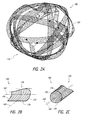
- Figure 2A depicts an embodiment of an occlusive device 100 that can be released into a target area of a body for occluding the target area.
- the target area can be a body lumen or space, such as aneurysms, including neurovascular or intracranial aneurysms, blood vessels, or other hollow anatomical structures.
- the device 100 can provide numerous and distinct advantages over other occlusive devices, such as coils and expandable filamentary structures, including stents, wire cages, and other known occlusive devices.
- the device 100 can pack or fill a target volume and accommodate the shape of the target volume, functions which stent or braided structures may not adequately perform on their own. Further, the device 100 can contact an irregular sidewall shape of the aneurysm. Furthermore, the device 100 can also maximize coverage of the aneurysm neck, adequately grip the sidewall of the aneurysm to prevent device herniation or slippage, promote a healing response along the aneurysm neck, provide predictable expansion to a desired expanded shape, and achieve these ends without requiring other framing or neck blocking devices, functions which coil structures may not adequately perform on their own.
- the device 100 is illustrated as comprising a body, ribbon, or elongate member 150 formed from a braid having a number of strands, such as metallic wires or polymeric filaments.
- the body 150 can comprise nitinol or other suitable superelastic materials.
- the material of which the body 150 is constructed can permit the body 150 to be substantially straight (and relatively elongated, for example, in the second configuration for delivery) while at or near room temperature and coiled (and relatively shortened or looped, for example, in the first configuration for space packing or filling in the target area) while at or near human body temperature.
- the device 100 can also comprise other types of materials or configurations of material.
- the device 100 can comprise a bioresorbable material or polymer. Further, the material can also comprise cobalt chromium.
- the device 100 can comprise a woven, knit, braided, or a non-braided, non-knit, and non-woven, single, continuous piece of material, or molded pieces, whether in a flat sheet or tubular configuration.
- the device 100 can comprise a single or multi-layer sheet or tubular structure.
- the device 100 can comprise a laser-cut or photo-etched material.
- the device 100 can also comprise a material formed from one or more non-woven fibers, e.g., long fibers, which are pressed or otherwise bonded together into a tubular or flat sheet configuration.
- the device 100 can be configured as a tubular structure, which can be flattened to provide a generally flat cross-sectional profile.
- the flattening of the tubular structure can thus provide a multi-layer sheet or structure whose layers are, incidentally, connected along the lateral longitudinal edges of the device.
- the device 100 can comprise a flat sheet, which can be folded onto itself one or more times along the longitudinal axis of the device 100.
- the folding of the material can thus provide a multi-layer sheet or structure.
- the use of such a sheet of material can provide ease of manufacturing and enable greater control of the ends of the device 100.
- the device 100 can comprise a body that has a textured surface or a smooth surface.
- the device can comprise a body that has an irregular, porous, dimpled, braided, woven, or knitted surface.
- some embodiments of the device 100 can be configured to provide pores, apertures, indentations, or interstitial spaces that impart a desired level of thrombogenicity and/or resistance to blood flow.
- such pores, apertures, indentations, or interstitial spaces can advantageously engage the sidewall of the aneurysm while being released into the aneurysm.
- a textured surface can tend to enhance wall apposition and ensure that the device 100 engages with the aneurysm wall and does not move within or herniate from the aneurysm.
- thrombogenic materials can be employed as coatings, additives or otherwise in the device 100, for example gold, platinum, platinum-iridium alloy, or fibrin.
- the braid wire metals may be selected to maximize the electrical currents (and any resulting thrombogenicity).
- the device 100 shown in Figure 2A can be loaded into a delivery system, such as a catheter, and delivered to a target area within the body.
- the device 100 when released from the delivery system in the target area, the device 100 can assume an expanded, first, or primary configuration 110, as shown in Figures 2A-2B .
- the device 100 when the device 100 is being delivered to the target area, can also have a collapsed, second, or secondary configuration 120, such as that shown in the embodiment in Figure 2C .
- the body 150 can be positioned in a configuration such as the collapsed configuration 120 when in a delivery catheter.
- the body 150 Upon being released from the delivery catheter, the body 150 can preferentially assume the expanded configuration 110. Accordingly, when unconstrained, the body 150 may tend to self-adjust or move to the expanded configuration 110 (as opposed to staying in or moving to the collapsed configuration 120).
- a body 150 of the device 100 can be looped, curved, curled, or rolled about an axis that is transverse to a longitudinal axis 160 of the body 150.
- a body 150 of the device 100 in the collapsed configuration 120 shown in Figure 2C (e.g., achieved when the device 100 is in a catheter), can be looped, curved, curled, or rolled about an axis that is aligned with a longitudinal axis 160 of the body 150.
- the body 150 can comprise a "curl vector" 162 that can be geometrically defined, using the "right-hand rule," as the resulting vector or direction in which the thumb points when the fingers of the hand are curled along the same arc or orientation of the body 150.
- the curl vector 162 when in the expanded configuration 110, can be oriented substantially transverse relative to the longitudinal axis 160 of the body. In some embodiments, the curl vector 162 can extend in a generally perpendicular direction relative to the longitudinal axis 160 when the body 150 is in the expanded configuration 110.
- the body 150 can comprise opposing first and second side edges 172, 174.
- the first and second side edges 172, 174 can be spaced apart at a first distance.
- the device 100 can comprise a leading edge 176 (which can represent a cross-section of the device that is substantially perpendicular to the longitudinal axis 160), which can have a substantially flat cross-sectional shape when the device 100 is in the expanded configuration 110.
- the device 100 can substantially pack or fill the internal volume of the body lumen, such as an aneurysm, after being released from a delivery system.
- the device 100 when the device 100 is in the expanded configuration 110, the device 100 can comprise a variety of three-dimensional shapes, including spherical or non-spherical shapes, including, hemispheres, noodles, coils, prolate spheroids, oblate spheroids, bowls, non-spherical surfaces of revolution (e.g., toruses, cones, cylinders, or other shapes rotated about a center point or coplanar axis), and/or combinations thereof.
- Figure 2A illustrates an embodiment of the device having a ball-shaped or substantially spherical configuration
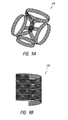
- Figures 9A-9B illustrate embodiments of a device 100 having a semi-cylindrical, 3-D, or cylindrical configurations.
- the body 150 can have a substantially cylindrical configuration.
- the body 150 can be curved, curled, or rolled around or about a line substantially parallel relative to the longitudinal axis 160.
- the body 150 when in the collapsed configuration 120, can be curled such that the curl vector 162 can be oriented substantially parallel relative to the longitudinal axis 160 of the body.
- the curl vector 162 when the body 150 is in the collapsed configuration 120, even though the curl vector 162 may not be substantially parallel relative to the longitudinal axis 160, the curl vector 162 can be within about 30°, within about 20°, or within about 10° of parallel relative to the longitudinal axis 160.
- the first and second side edges 172, 174 can be curled toward each other.
- the first and second side edges 172, 174 can be spaced apart at the first distance.
- the first and second side edges 172, 174 can be spaced apart at a second distance, which is less than the first distance.
- the leading edge 176 of the device 100 (which can represent a cross-section of the device that is substantially perpendicular to the longitudinal axis 160) can have a curved shape or cross-section when the device 100 is in the collapsed configuration 110.
- first and second side edges 172, 174 can be substantially parallel relative to each other in the collapsed configuration 120.
- first and second side edges 172, 174 can extend substantially parallel relative to the longitudinal axis 160.
- first and second side edges 172, 174 can also extend at least partially helically about the longitudinal axis 160 in the collapsed configuration 120.
- the first and second side edges 172, 174 may slightly deflect, bend, or curve onto the longitudinal axis 160 while passing through tortuousities of the vasculature.
- such motion is considered typical during advancement of the device 100 to the target area and when device 100 is positioned in the collapsed, second configuration 120 within the catheter, the device 100 is considered to be in the collapsed configuration 120 regardless of the degree or amount of curving or looping of the device 100 onto the longitudinal axis 160.
- some embodiments can provide a device that is sufficiently flexible to bend or deflect while advancing through tortuosities of the vasculature without kinking or breaking fibers or filaments of the device. Further, some embodiments also allow the device 100 to be subjected to substantial pushing forces without collapsing or buckling. For example, some embodiments allow the device to be positioned in a generally tubular or rolled shape, thus advantageously increasing the strength of the device when under axial compression in the collapsed configuration.
- the body 150 of the device 100 can be configured to have at least one preset configurations.
- the body 150 of the device 100 can be biased such that the device 100 assumes a first preset two or three-dimensional configuration in the expanded configuration 110.
- the body 150 of the device 100 can also comprise a second preset configuration in which the device 100 assumes the collapsed configuration 120.
- the body 150 of the device 100 can be biased toward one or both of the first or second preset configurations.
- the device 100 can also be preset to assume the first configuration as a primary configuration and to assume the second configuration is a secondary configuration.
- the body 150 of the device 100 can have dual stable positions.
- the first configuration can be preferred when no external forces are being exerted upon the body 150.
- the device has only one or both of these preset configurations.
- the device 100 may have only a preset expanded configuration 110
- the device 100 can be rolled or curled sufficiently to permit loading and advancement of the device 100 within a catheter.
- the body 150 of the device 100 may have only a preset collapsed configuration 120
- the device 100 can incorporate another structure, such as the tensioning member discussed below, to impart a two or three-dimensional shape to the device 100.
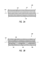
- Figures 3A-3I show top views of various embodiments of an occlusive device in a planar or flat configuration, for purposes of illustration. Any of the devices illustrated in Figures 3A-3I can be formed using a tubular mesh material that is flattened into a two-layer sheet. However, any of the devices illustrated in Figures 3A-3I can also be configured as a single layer sheet of mesh material, which can be folded once, twice, or more times, or not at all in forming the device. Cross-sectional profiles of some embodiments are illustrated in Figures 5A-6B .
- the device whether formed from a flattened tubular mesh or a single layer sheet (folded or not), can optionally comprise one or more features, such as slits or protrusions that can facilitate access through the device or increase the coverage of the device in its expanded configuration.
- Other features can also be optionally incorporated into the device to provide radiopacity to the device, a drug delivery means, swellable materials, or other features such as those disclosed herein or known in the art.
- Figure 3A illustrates a section of the device 100 in which the body 150 is configured such that the first and second edges 172, 174 are substantially straight or extend substantially parallel relative to the longitudinal axis 160 of the device 100.
- Figure 3B illustrates that the device 100 can optionally comprise at least one longitudinal slit.
- the device 100 can comprise at least one slit 190 extending along the longitudinal axis 160 of the device 100.
- the device 100 can comprise a plurality of slits 190, such as that shown in Figure 3B .
- the slit 190 can permit the clinician to advance or inject another embolic device, such as one or more coils or an embolic material or liquid, into the aneurysm.
- a suitable liquid embolic is the OnyxTM liquid embolic system manufactured by Covidien LP, Irvine, CA.
- OnyxTM liquid embolic system is a non-adhesive liquid used in the treatment of brain arteriovenous malformations.
- OnyxTM liquid embolic system is comprised of an ethylene vinyl alcohol (“EVOH”) copolymer dissolved in dimethyl sulfoxide (“DMSO”), and suspended micronized tantalum powder to provide contrast for visualization under fluoroscopy.
- EVOH ethylene vinyl alcohol
- DMSO dimethyl sulfoxide
- Other liquid embolic solutions are also envisioned.
- Figure 3C illustrates that in some embodiments, the device 100 can optionally comprise a shape-imparting, structural, or tensioning member 194.
- the body 150 can be formed separately from the tensioning member 194 such that the tensioning member 194 acts as a separate, independent component that influences the shape of the body 150.
- the tensioning member 194 can be interwoven into the braid.
- the tensioning member 194 can be coupled to one or more sections of the device 100 in order to provide stretch resistant or anti-stretch properties to the device 100.
- the device 100 can be formed from a resilient or deformable material, the incorporation of the tensioning member 194 can ensure that the length of the device 100 varies only slightly or is substantially unchanged during advancement of the device 100 through the delivery system and during expansion of the device 100 within the target area.
- the tensioning member 194 can resiliently provide stretch resistance.
- the length of the device 100 can increase and the tensioning member 194 can resist the stretching and urge the device 100 toward its unstretched, original length.
- the tensioning member 194 may not only provide anti-stretch capabilities, but can also impart a two or three-dimensional configuration to the device 100 when in the expanded configuration 110.
- the tensioning member 194 may be employed to impart any of the two or three-dimensional configurations discussed herein, or other suitable such configurations.
- a desired unconstrained configuration can be heat-set or otherwise processed into the tensioning member 194.
- the tensioning member 194 can be employed with a device 100 which itself has no particular heat-set or otherwise preset unconstrained configuration, or with a device 100 which does have a preset two or three-dimensional configuration. Where only the tensioning member 194 has a preset unconstrained configuration, the tensioning member 194 can urge the device 100 into a two or three-dimensional unconstrained or semi-constrained configuration upon release from a delivery catheter or into the target area.
- the unconstrained configuration thus achieved by the device 100 can be generally similar to the unconstrained configuration that is preset in the tensioning member 194.
- the tensioning member 194 can comprise first and second ends, with at least one of the ends being coupled to the body 150 of the device 100. In some embodiments, the tensioning member 194 can comprise first and second ends that are each coupled to respective first and second portions of the device 100. The first and second portions of the device 100 can comprise first and second end portions.
- the tensioning member 194 can facilitate delivery of the device 100 by providing either a pulling or pushing function during advancement of the device 100.
- the tensioning member 194 can be coupled at one end to only one portion or end of the device 100.
- the other end of the tensioning member 194 can be grasped or coupled to a portion of the delivery system for providing anti-stretch properties.
- the device 100 can be delivered within a catheter using a core wire or assembly that comprises a pad or engagement member at its distal end.
- the engagement member of the core wire can engage the device 100 at a point distal to a proximal end of the device 100.
- the engagement member can engage the device 100 at a point proximal to the distal end of the device 100, such as at a midpoint along the longitudinal axis of the device 100, or between the midpoint and the distal end of the device 100.
- the tensioning member 194 can be coupled to the proximal end of the device 100 and extend distally such that a distal end of the tensioning member 194 is engaged with a portion of the core wire, such as the engagement member.
- the distal end of the tensioning member 194 can be frictionally engaged between the engagement member and the device 100 or otherwise releasably engaged with the core wire.
- the tensioning member 194 can be attached to a distal end of the core wire or engagement member and a proximal end of the device 100 and be configured to dissolve upon release of the device 100 within the target area.
- the tensioning member 194 can provide column strength to the device 100.
- the tensioning member 194 may be used to urge the device 100 distally through the catheter during delivery of the device 100 by manually pushing a proximally extending portion of the tensioning member 194 in a distal direction.
- the tensioning member 194 can be coupled to a distal end portion of the body 150 of the device 100 and a proximal end of the tensioning member 194 can be contacted (and some embodiments, along with a proximal end of the body 150) to push the device 100 distally through a catheter lumen.
- some embodiments of the delivery system can be configured to abut or the coupled to a proximal end of the tensioning member 194 for pushing the device 100 through the catheter.
- the tensioning member 194 which can be formed separately from the body 150, may comprise one or more nitinol wires, which can be pre-shaped as discussed above.
- nitinol or AUSTENITIC nitinol or other material
- Such a tensioning member can be used as discussed above to maintain an axial length of the device 100 during delivery through a catheter lumen, but permit or facilitate movement from the collapsed configuration 120 to the expanded configuration 110.
- some embodiments can be provided in which the tensioning member 194 imparts a two or three-dimensional shape to the device 100 upon release from the catheter.
- the body 150 of the device 100 can be configured such that the edges 172, 174 converge or diverge relative to each other.
- the body 150 can comprise one or more enlarged portions, which can comprise wings, bulges, that extend laterally outward from the longitudinal axis 160 of the body 150.
- Figure 3D illustrates a plurality of enlarged portions 200 that extend generally symmetrically from opposing sides of the device 100.
- Figure 3E illustrates another embodiment of the device 100 in which enlarged portions 200 extend in a staggered configuration from opposing sides of the device 100.
- Figure 3G illustrates another embodiment in which the enlarged portions 200 have different widths or sizes.
- the shape and dimensions of the enlarged portions 200 can, as illustrated, provide the enlarged portions 200 with a rounded, semicircular edge. However, the enlarged portions or wings 200 can also be configured such that the edges 172, 174 have a sinusoidal shape.
- the enlarged portions can comprise any shape, size, or occupy any position along the length of the device, and any combinations thereof.
- the enlarged portions 200 can be formed from a single, continuous piece of material with the body 150.
- the body 150 can be cut or otherwise shaped to include the enlarged portions 200.
- the body 150 can be formed from a braided sheet or tube whose filaments are stretched laterally and heat-set to form the enlarged portions 200.
- the enlarged portions 200 can be formed separately from and subsequently coupled to the body 150.
- the enlarged portions 200 can be configured to roll or curl about the longitudinal axis 160 or to laterally self-expand from a compressed configuration.
- the embodiments illustrated in Figures 3D-3E illustrate rollable or curlable enlarged portions 200.
- Figures 3F-3G illustrate embodiments of the device 100 in which the enlarged portions 200 are in respective compressed and expanded positions 210, 212.
- the enlarged portions 200 can cause the pic count (i.e., the count of the per-inch-crossings of filaments or pics-per-inch (PPI)) or fiber density along those portions of the body 150 to be higher where the enlarged portions 200 are disposed.
- the enlarged portions 200 can move from the compressed position 210 to the expanded position 212, as shown in Figures 3F-3G .
- the enlarged portions 200 can be superelastic.
- the edges 172, 174 along the enlarged portions 200 can be spaced apart greater than the edges 172, 174 along the body 150.
- the edges 172, 174 can have a maximum width (for example, measured at a distance 220 in Figure 3G ) and a minimum width (for example, measured at a distance 222 in Figure 3G ).
- the maximum width 220 can be greater than the minimum width 222.
- the maximum width 220 can be from about 1.1 to about 4 times as large, from about 1.5 to about 3.5 times as large, from about 2 to about 3 times as large, or from about 2.2 to about 2.8 times as large as the minimum width 222. In some embodiments, the maximum width 220 may not exceed more than three or four times the minimum width 222.
- the enlarged portion or wing 200 can comprise a width 224 that is approximately equal to the minimum width 222. Furthermore, and some embodiments, the width 224 of the enlarged portion or wing 200 can be between about 0.25 and about 2 times, about 0.5 to about 1.5 times, about 1 and about 1.25 times the minimum width 222.
- the enlarged portions 200 can be configured to have different widths, sizes (e.g., longitudinal lengths), or shapes along the length of the device 100.
- the edges 172, 174 can define a generally irregular pattern.
- the maximum and minimum widths 220, 222 can be within the range, such as those discussed above.
- the enlarged portions 200 can be configured to provide a fiber density or pattern that is substantially equivalent or identical to the fiber density or pattern of the body 150. However, the enlarged portions 200 can also be configured to provide a lower fiber density or different pattern than portions of the body 150 disposed adjacent to the respective enlarged portion or wing 200. In such embodiments, the enlarged portions 200 can be heat-set or otherwise pre-shaped in such a configuration.
- the enlarged portions 200 can be formed by stretching the body 150 to widen it at discrete locations along its length or by coupling a separate component to the body 150.
- the enlarged portions 200 can be maintained in the compressed position by exertion of a compressing force or by the use of a coating on the device 100, which can assist in maintaining the compressed position until the coating dissolves in the presence of fluid after release.
- the body 150 can comprise first and second sections 240, 242 that can have different properties.
- the body 150 can be configured such that a braid, weave, or knit pattern changes at least once or more or varies along the length of the body 150.
- the body 150 can comprise a braided structure that comprises first and second sections 240, 242.
- the first and second sections 240, 242 can have different porosities, pic counts, filament pitch, filament size, or braid/weave/knit densities.
- the first and second sections 240, 242 can have different properties that can advantageously affect the function of the device 100 within the target area and during delivery to the target area.
- a higher pic count or braid density can tend to reduce or block flow through the device 100, while a lower pic count or braid density can permit flow or injection of embolic materials or coils through the device 100.
- the pic count or braid density can also influence the frictional engagement with the target area wall and endothelialization when released, for example, at the neck of an aneurysm.
- the pitch or alignment of the filaments can also affect longitudinal compressibility or pushability when urging the device 100 distally within the catheter toward the target area.
- the fibers can be closely axially aligned with the longitudinal axis of the device 100, thus enhancing or increasing pushability of the device 100.
- a lower pic count can also tend to increase pushability of the device 100.
- the device 100 can also be configured such that at least one of the proximal and distal ends 250, 252 of the device 100 comprise an atraumatic feature or component.
- the device 100 can be configured such that the proximal and/or distal ends 250, 252 comprises one or more points or corners (whether rounded or pointed) having a filament 260 extending therefrom.
- the filament 260 can allow the proximal and/or distal ends 250, 252 to gently and atraumatically contact the target area wall (such as an aneurysm wall).
- the filament 260 can comprise a rounded or ball-shaped tip 262.
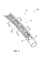
- Figures 4-6B illustrate views of a device assembly 300 in which a device 100 is disposed within a catheter 302.
- the device 100 is in the collapsed configuration 120.
- the device 100 comprises enlarged portions 200 that are folded or curled around the longitudinal axis of the device 100.
- the device 100 also comprises atraumatic portions or filaments 260.
- the device 100 can be distally pushed out of the catheter 302 and into a target aneurysm whereat the device 100 can expand from the collapsed configuration 120 to the expanded configuration.
- the device 100 can comprise a radiopaque marker at one or both of its ends, at locations along the length thereof, or along the entire length thereof.
- markers can be configured similar to the filament 260 and/or the rounded or ball-shaped tip 262 thereof.
- the filament 260 and/or the rounded or ball-shape tip 262 thereof can be radiopaque.
- the length of the device 100 can be from about 5 mm to about 250 mm. In some embodiments, the length can be from about 7 mm to about 180 mm. Further, the length can be from about 9 mm to about 100 mm. Furthermore, the length can be from about 10 mm to about 50 mm. The length of the device 100 can also be about 25 mm. As noted below, multiple devices having multiple lengths and/or configurations can also be used.
- the device can be configured such that a wall of the device 100 comprises a flow diverting pore size.
- a "flow diverting pore size” can refer to an average pore size of pores (in at least a section of a device) that is sufficiently small enough to interfere with or inhibit fluid exchange through the pores of that section.
- a device 100 (e.g., at least a proximal section of the device) can have an active section or a flow diverting section with a flow diverting pore size when the pores of the section are sized to inhibit flow of blood through the sidewall into an aneurysm to a degree sufficient to lead to thrombosis and healing of the aneurysm when the tubular member is positioned in a blood vessel and adjacent to the aneurysm.
- a flow diverting pore size can be achieved when pores in the flow diverting or active section have an average pore size of less than about 500 microns when the device (e.g., stent) is in the expanded state.
- the average pore size can be less than about 320 microns.
- the average pore size can be from about 25 microns to about 350 microns.
- the average pore size can also be from about 40 microns to about 200 microns.
- the average pore size can be from about 60 microns to about 150 microns.
- the average pore size can be about 120 microns.
- Average pore sizes that are about within such ranges can operate to divert fluid flow and induce thrombosis within the lumen or interior volume enclosed by the wall.
- the pores can have a pore size that is generally constant.
- the pores can have an average pore size that is measured using an inscribed circle diameter.
- a device 100 can be provided with a porosity in the range of 10%-95% may be employed in the expanded braid to achieve these effects. In some embodiments, a porosity in the range of about 30% to about 90% may be employed to achieve these effects. Further, a porosity in the range of about 50% to about 85% may be employed to achieve these effects.
- Other various features can be incorporated into the device 100, such as those disclosed in copending International Application No. PCT/US13/33419, filed March 22, 2013 , the entirety of which is incorporated herein by reference.
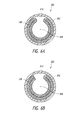
- Figures 5A-5B illustrate cross-sectional views of the device 100 and catheter 302 taken along section lines 5A-5A and 5B-5B of Figure 4 . Similar to the view illustrated in Figure 2C , Figures 5A-5B illustrate a cross-sectional view of the device 100 in which the device is curved, curled, or rolled around or about a line 304 substantially parallel relative to the longitudinal axis 160 of the device 100.
- Figures 6A-6B also illustrate other embodiments of the device in which the device is folded or compressed from a tubular or sheet configuration.
- the device 100 can comprise a tubular shape that is flattened and curved, curled, or rolled around or about a line 304 substantially parallel relative to the longitudinal axis 160.
- Figure 6B illustrates that the device 100 can comprise a sheet that is folded at least once and curved, curled, or rolled around or about a line 304 substantially parallel relative to the longitudinal axis 160.
- the device 100 can exhibit improved or high pushability relative to comparable devices or structures by virtue of its collapsed configuration 120.
- the collapsed configuration 120 can improve pushability by reducing the amount of exposed material in contact with the catheter inner wall and/or by causing the collapse device to contact less than the full circumference of the catheter inner wall.
- the device 100 is in a curved, curled, or rolled shape in the collapsed configuration 120, at least a portion of the device 100 will not come in contact with an interior surface or wall 310 of the catheter 302. In some embodiments, the interior wall 310 can be contacted along less than its full circumference. In its collapsed configuration 120, the device 100 will require much less pushing force than comparable structures that are otherwise simply radially collapsed or compressed from an expanded diameter to a compressed diameter (thereby either increasing the braid density or the axial length of the device in the collapsed state), as is typical with stents and other braided structures, such as braid balls.
- the device 100 can be rolled onto itself such that a cross-sectional inner portion of the device is radially within a cross-sectional outer portion of the device.
- the cross-sectional inner portion of the device can be, for purposes of this disclosure, considered as the rolled portion of the device that is radially overlapped by another portion of the device. As such, only the cross-sectional outer portion of the device will contact the inner wall 310 of the catheter 302.
- the curled device 100 can extend along less than the entire circumference of the inner wall 310 of the catheter 302. As shown, in its folded or compressed, flattened cross-sectional configuration (which can be assumed in the expanded configuration, as illustrated in Figure 2B ), a cross-sectional width of the device 100 can be less than the circumference of the inner wall 310.
- the device 100 can be flattened or folded, and in some embodiments, rolled onto itself.
- the width of the flattened cross-section can be between about 3 mm and about 7 mm, between about 4 mm and about 6 mm, or about 5 mm. Such dimensions can be used for single layer or multi-layer flattened cross-sections.
- the device can be formed from a flat sheet.
- the flat sheet can have a width of between about 6 mm and about 14 mm, between about 8 mm and about 12 mm, or about 10 mm. Similar metrics can be followed when the device is formed using a folded sheet that has a trifold cross-section.
- the cross-sectional diameter of the rolled, flattened material can be between about 1 mm and about 4 mm, between about 1.5 mm and about 3.5 mm, or between about 2 mm and about 3 mm.
- the cross-sectional diameter of the device, when rolled onto itself, can also tend to depend on the ability of the material to roll up in a delivery tube or catheter (e.g., its bending strength).
- the collapsed configuration 120 of the device 100 can allow a greater amount of material or device to be advanced through the catheter 302 while minimizing the frictional resistance between the device 100 and catheter wall 310. As a result, the pushability of the device 100 can be advantageously improved.
- the various delivery methods and systems can also be provided.
- one or more devices can be delivered using the systems disclosed herein in combination with a catheter.
- the device delivery system can comprise an elongate tube or catheter which slidably receives a core assembly configured to carry the device through the catheter.
- the catheter can have a proximal end and an opposing distal end which can be positioned at a treatment site within a patient, an internal lumen extending from the proximal end to the distal end, and an inner surface or wall facing the lumen.
- the catheter has a distal opening through which the core assembly and/or the device may be advanced beyond the distal end in order to expand, release, or deploy the device within the target area, such as a blood vessel or aneurysm.
- the proximal end may include a catheter hub.
- the catheter can define a generally longitudinal axis A-A extending between the proximal end and the distal end. When the delivery system is in use, the longitudinal axis need not be straight along some or any of its length.
- the catheter can optionally comprise a microcatheter.
- the catheter can optionally comprise any of the various lengths of the MARKSMANTM catheter available from Covidien LP of Irvine, California USA.
- the catheter can optionally comprise a microcatheter having an inner diameter of about 0.030 inches or less, and/or an outer diameter of 3 Fr or less near the distal end.
- the catheter can comprise a microcatheter which is configured to percutaneously access the internal carotid artery, or a location within the neurovasculature distal of the internal carotid artery, with its distal opening.
- Figures 7A-7F illustrate aspects of a delivery assembly 300 and occlusive device 100 that has been advanced to a target aneurysm 400.
- the device 100 can be advanced through a neck 402 of the aneurysm 400 toward the fundus 404 of the aneurysm 400.
- the device 100 can tend to uncurl, unroll, or expand from its collapsed configuration such that the opposing edges of the device move apart from each other and the released portion of the device 100 begins to assume a generally flat cross-sectional configuration.
- the enlarged portions 200 of the device 100 and the body 150 of the device 100 can contact the inner wall or fundus 404 of the aneurysm 400.
- the device 100 can tend to frictionally contact or engage the inner wall of the aneurysm 400, thus reducing or eliminating slipping or sliding against the inner wall of the aneurysm 400, while maintaining the ability of the device 100 to conform and move freely within the aneurysm 400 during initial expansion and entry of the device 100 into the aneurysm 400.
- the device 100 can tend to engage the inner wall of the aneurysm 400.
- Such engagement can allow the clinician to better predict the deployment characteristics or released position of the device 100 within the aneurysm 400. Additionally, such engagement can also enable the device 100 to be more securely retained within the aneurysm 400, thereby avoiding herniation of the device 100 from within the aneurysm 400.
- the neck 402 will tend to be fully covered or blocked.
- the wings 200 and body 150 will tend to engage the inner wall of the aneurysm 400 extending over the neck 402.
- the volume of the aneurysm 400 can be substantially packed or filled such that circulation or fluid movement is slowed or stopped within the aneurysm 400 and in to the aneurysm 400 through the neck 402 is substantially slowed or stopped.
- Figure 8 illustrates a view into the aneurysm 400 from below the aneurysm neck 402 after the device 100 or multiple devices are released into the aneurysm 400.
- the use of devices having the enlarged portions 200 can further improve the coverage of the neck 402 and engagement with the sidewall of the aneurysm 400.
- substantial coverage of the aneurysm neck 402 using a device that has a textured surface, such as those mentioned above, including the braided or coated surfaces, can beneficially facilitate and invoke a healing response.
- superior neck coverage can allow endothelialization to more easily take place at the neck 402.
- some embodiments can be provided in which a single device is used to treat a wide neck aneurysm, in contrast to traditional treatments that require both a coil and the placement of a stent or other framing structure to prevent herniation of the coil from within the wide neck aneurysm.
- the delivery of one or more occlusive devices can be performed by delivering only a single occlusive device or multiple occlusive devices.
- a first device can be released into the aneurysm that can function as the outermost layer of the group of devices deployed into the aneurysm.
- Subsequent devices can thereafter be inserted within the first framing device within the aneurysm.
- Such additional devices can comprise finishing coils or additional devices, such as those disclosed herein.
- the size and/or shape of the coils or devices subsequently released into the aneurysm can be progressively smaller or of a substantially identical or different size and/or shape.
- one or more devices can be delivered into the aneurysm without requiring the use of a framing structure to hold the devices within the aneurysm, which is required when using coils.
- the devices disclosed herein can provide excellent neck coverage.
- the devices disclosed herein can reliably and predictably expand to preset shapes or configurations.
- the devices disclosed herein can pack or fill the volume of the target space, such as an aneurysm, much as coils are able to do.
- the length of the devices can be between about 1 cm to about 10 cm.
- the order of delivery of such devices can be in order of progressive decrease in size.
- the clinician can start with an 8 mm device, followed by one or more 7 mm devices, followed by one or more 6 mm devices, and so forth.
- the device 100 can comprise a nitinol or other material that tends to have a highly predictable shape when in the relaxed or released position.
- a clinician can provide a specifically shaped device to a target area of a specific shape or size.
- Such tailored therapy can improve the outcome for patients.
- the apparatus and methods discussed herein are not limited to the deployment and use of a medical device within the vascular system but may include any number of further treatment applications.
- Other treatment sites may include areas or regions of the body including any hollow anatomical structures.
Abstract
Description
- The present disclosures relate to implantable devices. More specifically, the present disclosures relate to occlusive devices that can be implanted endovascularly, and in some embodiments, for aneurysm therapy.
- Numerous embolization devices have been provided for aneurysm treatment. Generally, braid-ball embolic devices, coils, and other types of embolization operate through blood flow disruption and subsequent thrombus formation. Currently, aneurysms are treated with embolic coils, such as Covidien Axium™ or Stryker GDC® 10. These embolic devices are small coils with outside diameters ranging from 0.0090 inches to 0.0145 inches. The devices are heat treated on mandrels to impart a two or three-dimensional shape that are favorable for aneurysm geometries.
- At least one aspect of the disclosure provides methods and apparatuses for delivering an occluding device or devices (e.g., stent or stents) in the body. The occluding device can easily conform to the shape of the tortuous vessels of the vasculature. The occluding device can be used in a variety of applications. For example, in some embodiments, the occluding device can direct the blood flow within a vessel away from an aneurysm by substantially or fully blocking a neck of the aneurysm or substantially or fully disrupting blood flow within an aneurysm. Further, embodiments of the occluding devices disclosed herein provide numerous advantages in a single device that were only available previously by using a combination of different medical devices.
- In accordance with some embodiments, a device is disclosed that can have a flattened profile and formed from either a tubular material or a flat sheet. The device can be heat treated to impart a two or three-dimensional shape.
- The device can be made from polymers, metals or a combination of polymers and metals. The device can be braided, knitted or woven with multiple filaments within a single stitch or carrier. Radiopaque filaments can be added to enhance visibility during and after delivery to target vasculature. Embodiments of the device can have a wider profile than a coil and therefore, compared to coils, require fewer devices to obtain adequate aneurysm neck coverage and aneurysm sac stasis. The device can also provide superior framing support of the aneurysm sac.
- In accordance with some embodiments, a method of delivering one or more devices comprises forming the device into a cylindrical or "spiral" shape and delivering it through a catheter. Forming the device into a cylindrical or spiral shape can minimize the crossing profile and allow access to distal anatomy. Thus, some embodiments can be used in vasculature that is smaller than that possible for traditional stents or other such expandable structures. Further, the pushing resistance of the device can be decreased, thereby improving the pushability of the device.
- The subject technology is illustrated, for example, according to various aspects described below. Various examples of aspects of the subject technology are described as numbered clauses or embodiments (1, 2, 3, etc.) for convenience. These are provided as examples and do not limit the subject technology. It is noted that any of the dependent clauses may be combined in any combination with each other or one or more other independent clauses, to form an independent clause. The other clauses can be presented in a similar manner. The following is a non-limiting summary of some embodiments presented herein:
- Clause 1. An occlusive device for occluding a target area, comprising: an elongate member having opposing first and second side edges extending longitudinally along the member and a member width, the member having (i) a collapsed configuration in which the first and second side edges are curled toward each other about a longitudinal axis of the member, and (ii) an expanded configuration in which the member form a series of loops and the first and second side edges uncurl to be spaced apart from each other.
- Clause 2. The device of Clause 1, wherein the first and second side edges uncurl to be spaced apart from each other at no more than twice the member width.
- Clause 3. The device of Clause 2, wherein the first and second side edges uncurl to be spaced apart from each other at approximately the member width.
- Clause 4. The device of any one of the preceding clauses, wherein the elongate member comprises a shape memory material.
- Clause 5. The device of Clause 4, wherein the elongate member comprises a material that is in austenite state when in the expanded configuration.
- Clause 6. The device of any one of the preceding clauses, wherein the elongate member comprises a flattened tubular member.
- Clause 7. The device of any one of the preceding clauses, wherein the member comprises a plurality of filaments.
-
Clause 8. The device of Clause 7, wherein a spacing of the filaments varies along the length of the member. - Clause 9. The device of Clause 7, wherein the plurality of filaments are braided together.
-
Clause 10. The device of Clause 7, wherein the plurality of filaments are woven together. - Clause 11. The device of Clause 7, wherein the member is configured such that the filaments form a flat tubular member.
-
Clause 12. The device of Clause 11, wherein the filaments of the tubular member have a variable pitch. - Clause 13. The device of any one of the preceding clauses, wherein the elongate member comprises at least one slit.
- Clause 14. The device of Clause 13, wherein the at least one slit extends along the longitudinal axis of the member.
- Clause 15. The device of Clause 13, wherein the elongate member comprises a plurality of slits extending along the longitudinal axis of the member and spaced apart in a substantially linear configuration.
- Clause 16. The device of any one of the preceding clauses, wherein the first and second side edges comprise a plurality of wing elements extending laterally therefrom.
- Clause 17. The device of Clause 16, wherein the wing elements extend from opposing sides of the elongate member.
- Clause 18. The device of Clause 17, wherein a pair of wing elements extend from opposing sides at a first longitudinal position along the member.
- Clause 19. The device of Clause 17, wherein the wing elements comprise first and second sets of wing elements, the first set extending from a first side of the member and the second set extending from a second side of the member at different longitudinal positions than the first set.
-
Clause 20. An occlusive device for occluding a target area, comprising: a elongate member comprising a plurality of filaments, the member having a central backbone and a plurality of wing elements extending from the backbone, the member having (i) a collapsed configuration in which the wings are curled toward the backbone about a longitudinal axis of the member, and (ii) an expanded configuration in which the backbone forms a series of loops. - Clause 21. The device of
Clause 20, wherein the wing elements extend from opposing sides of the elongate member. -
Clause 22. The device of any one of Clauses 20-21, wherein the wing elements comprise first and second sets of wing elements, the first set extending from a first side of the member and the second set extending from a second side of the member at different longitudinal positions than the first set. - Clause 23. The device of any one of Clauses 20-22, wherein the elongate member comprises a flat, braided tubular member.
- Clause 24. The device of any one of Clauses 20-23, wherein the wings uncurl away from the backbone in the expanded configuration.
- Clause 25. A method of operating an occlusive device assembly, comprising: advancing an elongate member in a collapsed configuration within a catheter, the member having opposing first and second side edges extending longitudinally along the member, the first and second side edges being curled toward each other about a longitudinal axis of the member in the collapsed configuration; and urging a distal end of the member beyond the catheter distal end to release the member to an expanded configuration in which the first and second side edges move away from each other and the member curls into a series of loops.
- Clause 26. The method of Clause 25, further comprising positioning the catheter distal end at an ostium of an aneurysm, wherein the urging comprises urging the member into a fundus of the aneurysm.
- Additional features and advantages of the subject technology will be set forth in the description below, and in part will be apparent from the description, or may be learned by practice of the subject technology. The advantages of the subject technology will be realized and attained by the structure particularly pointed out in the written description and embodiments hereof as well as the appended drawings.
- It is to be understood that both the foregoing general description and the following detailed description are exemplary and explanatory and are intended to provide further explanation of the subject technology.
- The accompanying drawings, which are included to provide further understanding of the subject technology and are incorporated in and constitute a part of this specification, illustrate aspects of the disclosure and together with the description serve to explain the principles of the subject technology.
-
Figure 1 is a side cross-sectional view illustrating deployment of a device into an aneurysm, according to some embodiments. -
Figure 2A is a perspective view of an occlusive device that can be released into a target area of a body lumen, according to some embodiments. -
Figure 2B is a perspective, cross-sectional view of the device along its longitudinal axis, wherein the device is in a first, expanded configuration that can be achieved upon expansion within the target area, according to some embodiments. -
Figure 2C is a perspective, cross-sectional view of the device along its longitudinal axis, wherein the device is in a second, collapsed configuration that can be maintained during advancement to the target area, according to some embodiments. -
Figures 3A-3I illustrate aspects and optional features that can be incorporated into the device, according to some embodiments. -
Figure 4 illustrates a device in a collapsed configuration within a catheter, according to some embodiments. -
Figures 5A-6B illustrate cross-sectional views of a device disposed within a catheter, according to some embodiments. -
Figures 7A-7F illustrate progressive steps in the deployment of a device into an aneurysm, according to some embodiments. -
Figure 8 illustrates coverage of a neck of an aneurysm using one or more devices, according to some embodiments. -
Figures 9A-9B illustrate additional shapes of a device in an expanded configuration, according to some embodiments. - In the following detailed description, numerous specific details are set forth to provide a full understanding of the subject technology. It should be understood that the subject technology may be practiced without some of these specific details. In other instances, well-known structures and techniques have not been shown in detail so as not to obscure the subject technology.
- Further, while the present description sets forth specific details of various embodiments, it will be appreciated that the description is illustrative only and should not be construed in any way as limiting. Additionally, it is contemplated that although particular embodiments of the present inventions may be disclosed or shown in the context of aneurysm therapy, such embodiments can be used in other occlusive therapies within the vasculature. Furthermore, various applications of such embodiments and modifications thereto, which may occur to those who are skilled in the art, are also encompassed by the general concepts described herein.
- In accordance with an aspect of some embodiments disclosed herein, occlusive devices and methods of use are provided that provide advantages over, for example, the use of a traditional coil, a stent, or a braided structure, whether alone or in combination, in occluding an aneurysm. Some embodiments can provide a greater aneurysm surface contact than traditional coils, which can allow less device material to be deployed while tending to increase the surface area of the implanted occlusive device, which can result in increased thrombogenicity. Likelihood of aneurysm recanalization can be greatly reduced through some embodiments, which can provide excellent wall apposition and neck coverage. Further, some embodiments can also be easier to manipulate within the aneurysm dome or cavity. For example, the device can more easily conform to the interior shape of the aneurysm cavity. Furthermore, when an aneurysm begins to reduce in size, aspects of some embodiments allow the device to be deformable such that the device can be compressed or collapse in size to promote healing of the aneurysm, which may not generally possible using traditional coils or other devices.
- For example,
Figure 1 is a side cross-sectional view illustrating deployment of a device into an aneurysm, according to some embodiments. As shown, adevice 10 can be advanced to atarget aneurysm 40 using adevice assembly 20. Thedevice 10 can be advanced from acatheter 22 of theassembly 20 and through aneck 42 of theaneurysm 40 toward afundus 44 of theaneurysm 40. - The
device 10 can comprise abody 12, which can have an elongate shape. In some embodiments, thebody 12 can be disposed in a first configuration when positioned within thecatheter 22 and expand to a second configuration when released from thecatheter 22 into theaneurysm 40. For example, in some embodiments, the first configuration can be achieved when thebody 12 is constrained within thecatheter 22 and curled or rolled primarily in a direction transverse to a longitudinal axis of thebody 12. In some embodiments, the second configuration can be achieved when thebody 12 is released from thecatheter 22 and curled or rolled primarily in a direction along the longitudinal axis of thebody 12. Thus, as thebody 12 of thedevice 10 is released from thecatheter 22, a primary curl or roll of thedevice 10 can transition from one direction along the longitudinal axis to the other, such that the device morphs from an elongate, substantially tubular configuration to a bundled, rounded shape within theaneurysm 40. As thedevice 10 is released, thebody 12 can contact incrementally more of the aneurysm wall and cover more of theneck 42 of theaneurysm 40 until theneck 42 is substantially covered or blocked. Eventually, whether a single or multiple devices are inserted into theaneurysm 40, the wall of the aneurysm can be more completely contacted by device(s) and the volume of theaneurysm 40 can be substantially packed or filled such that circulation or fluid movement is slowed or stopped within theaneurysm 40 and in to theaneurysm 40 through theneck 42 is substantially slowed or stopped. -
Figure 2A depicts an embodiment of anocclusive device 100 that can be released into a target area of a body for occluding the target area. The target area can be a body lumen or space, such as aneurysms, including neurovascular or intracranial aneurysms, blood vessels, or other hollow anatomical structures. According to some embodiments, thedevice 100 can provide numerous and distinct advantages over other occlusive devices, such as coils and expandable filamentary structures, including stents, wire cages, and other known occlusive devices. - For example, in the case of aneurysm therapy, the
device 100 can pack or fill a target volume and accommodate the shape of the target volume, functions which stent or braided structures may not adequately perform on their own. Further, thedevice 100 can contact an irregular sidewall shape of the aneurysm. Furthermore, thedevice 100 can also maximize coverage of the aneurysm neck, adequately grip the sidewall of the aneurysm to prevent device herniation or slippage, promote a healing response along the aneurysm neck, provide predictable expansion to a desired expanded shape, and achieve these ends without requiring other framing or neck blocking devices, functions which coil structures may not adequately perform on their own. - Referring to
Figure 3A , thedevice 100 is illustrated as comprising a body, ribbon, orelongate member 150 formed from a braid having a number of strands, such as metallic wires or polymeric filaments. For example, thebody 150 can comprise nitinol or other suitable superelastic materials. For example, in accordance with some embodiments, the material of which thebody 150 is constructed can permit thebody 150 to be substantially straight (and relatively elongated, for example, in the second configuration for delivery) while at or near room temperature and coiled (and relatively shortened or looped, for example, in the first configuration for space packing or filling in the target area) while at or near human body temperature. However, in some embodiments, thedevice 100 can also comprise other types of materials or configurations of material. For example, thedevice 100 can comprise a bioresorbable material or polymer. Further, the material can also comprise cobalt chromium. - Further, the
device 100 can comprise a woven, knit, braided, or a non-braided, non-knit, and non-woven, single, continuous piece of material, or molded pieces, whether in a flat sheet or tubular configuration. Thedevice 100 can comprise a single or multi-layer sheet or tubular structure. In some embodiments, thedevice 100 can comprise a laser-cut or photo-etched material. Thedevice 100 can also comprise a material formed from one or more non-woven fibers, e.g., long fibers, which are pressed or otherwise bonded together into a tubular or flat sheet configuration. - In some embodiments, the
device 100 can be configured as a tubular structure, which can be flattened to provide a generally flat cross-sectional profile. The flattening of the tubular structure can thus provide a multi-layer sheet or structure whose layers are, incidentally, connected along the lateral longitudinal edges of the device. - In some embodiments, the
device 100 can comprise a flat sheet, which can be folded onto itself one or more times along the longitudinal axis of thedevice 100. The folding of the material can thus provide a multi-layer sheet or structure. The use of such a sheet of material can provide ease of manufacturing and enable greater control of the ends of thedevice 100. - In some embodiments, regardless of the material or configuration of the
device 100, thedevice 100 can comprise a body that has a textured surface or a smooth surface. For example, in some embodiments, the device can comprise a body that has an irregular, porous, dimpled, braided, woven, or knitted surface. Thus, some embodiments of thedevice 100 can be configured to provide pores, apertures, indentations, or interstitial spaces that impart a desired level of thrombogenicity and/or resistance to blood flow. Further, such pores, apertures, indentations, or interstitial spaces can advantageously engage the sidewall of the aneurysm while being released into the aneurysm. As such, during deployment of thedevice 100, a textured surface can tend to enhance wall apposition and ensure that thedevice 100 engages with the aneurysm wall and does not move within or herniate from the aneurysm. - Further, instead of or in addition to such a textured surface, thrombogenic materials can be employed as coatings, additives or otherwise in the
device 100, for example gold, platinum, platinum-iridium alloy, or fibrin. Where a braid is employed, the braid wire metals may be selected to maximize the electrical currents (and any resulting thrombogenicity). - In use, the
device 100 shown inFigure 2A can be loaded into a delivery system, such as a catheter, and delivered to a target area within the body. According to some embodiments, when released from the delivery system in the target area, thedevice 100 can assume an expanded, first, orprimary configuration 110, as shown inFigures 2A-2B . However, when thedevice 100 is being delivered to the target area, can also have a collapsed, second, orsecondary configuration 120, such as that shown in the embodiment inFigure 2C . Thus, to facilitate delivery of thedevice 100, thebody 150 can be positioned in a configuration such as thecollapsed configuration 120 when in a delivery catheter. Upon being released from the delivery catheter, thebody 150 can preferentially assume the expandedconfiguration 110. Accordingly, when unconstrained, thebody 150 may tend to self-adjust or move to the expanded configuration 110 (as opposed to staying in or moving to the collapsed configuration 120). - In the expanded
configuration 110 shown inFigures 2A-2B , abody 150 of thedevice 100 can be looped, curved, curled, or rolled about an axis that is transverse to alongitudinal axis 160 of thebody 150. Further, in thecollapsed configuration 120 shown inFigure 2C (e.g., achieved when thedevice 100 is in a catheter), abody 150 of thedevice 100 can be looped, curved, curled, or rolled about an axis that is aligned with alongitudinal axis 160 of thebody 150. - In some embodiments, the
body 150 can comprise a "curl vector" 162 that can be geometrically defined, using the "right-hand rule," as the resulting vector or direction in which the thumb points when the fingers of the hand are curled along the same arc or orientation of thebody 150. As shown inFigure 2B , when in the expandedconfiguration 110, thecurl vector 162 can be oriented substantially transverse relative to thelongitudinal axis 160 of the body. In some embodiments, thecurl vector 162 can extend in a generally perpendicular direction relative to thelongitudinal axis 160 when thebody 150 is in the expandedconfiguration 110. - For example, the
body 150 can comprise opposing first and second side edges 172, 174. In the expandedconfiguration 110, at a given point along thelongitudinal axis 160, the first and second side edges 172, 174 can be spaced apart at a first distance. Additionally, as shownFigure 2B , thedevice 100 can comprise a leading edge 176 (which can represent a cross-section of the device that is substantially perpendicular to the longitudinal axis 160), which can have a substantially flat cross-sectional shape when thedevice 100 is in the expandedconfiguration 110. - The
device 100 can substantially pack or fill the internal volume of the body lumen, such as an aneurysm, after being released from a delivery system. For example, as discussed further below, when thedevice 100 is in the expandedconfiguration 110, thedevice 100 can comprise a variety of three-dimensional shapes, including spherical or non-spherical shapes, including, hemispheres, noodles, coils, prolate spheroids, oblate spheroids, bowls, non-spherical surfaces of revolution (e.g., toruses, cones, cylinders, or other shapes rotated about a center point or coplanar axis), and/or combinations thereof. For example,Figure 2A illustrates an embodiment of the device having a ball-shaped or substantially spherical configuration whileFigures 9A-9B illustrate embodiments of adevice 100 having a semi-cylindrical, 3-D, or cylindrical configurations. - However, in the
collapsed configuration 120, illustrated inFigure 2C , thebody 150 can have a substantially cylindrical configuration. For example, thebody 150 can be curved, curled, or rolled around or about a line substantially parallel relative to thelongitudinal axis 160. As shown inFigure 2C , when in thecollapsed configuration 120, thebody 150 can be curled such that thecurl vector 162 can be oriented substantially parallel relative to thelongitudinal axis 160 of the body. When thebody 150 is in thecollapsed configuration 120, even though thecurl vector 162 may not be substantially parallel relative to thelongitudinal axis 160, thecurl vector 162 can be within about 30°, within about 20°, or within about 10° of parallel relative to thelongitudinal axis 160. Further, in thecollapsed configuration 120, the first and second side edges 172, 174 can be curled toward each other. - For example, as noted above, in the expanded
configuration 110, at a given point along thelongitudinal axis 160, the first and second side edges 172, 174 can be spaced apart at the first distance. When moved to thecollapsed configuration 120, at a given point along thelongitudinal axis 160, the first and second side edges 172, 174 can be spaced apart at a second distance, which is less than the first distance. Additionally, as shownFigure 2C , theleading edge 176 of the device 100 (which can represent a cross-section of the device that is substantially perpendicular to the longitudinal axis 160) can have a curved shape or cross-section when thedevice 100 is in thecollapsed configuration 110. - In some embodiments, the first and second side edges 172, 174 can be substantially parallel relative to each other in the
collapsed configuration 120. For example, the first and second side edges 172, 174 can extend substantially parallel relative to thelongitudinal axis 160. In some embodiments, the first and second side edges 172, 174 can also extend at least partially helically about thelongitudinal axis 160 in thecollapsed configuration 120. - During delivery of the
device 100, although curled or rolled about thelongitudinal axis 160 in thecollapsed configuration 120, the first and second side edges 172, 174 may slightly deflect, bend, or curve onto thelongitudinal axis 160 while passing through tortuousities of the vasculature. For purposes of this disclosure, such motion is considered typical during advancement of thedevice 100 to the target area and whendevice 100 is positioned in the collapsed,second configuration 120 within the catheter, thedevice 100 is considered to be in thecollapsed configuration 120 regardless of the degree or amount of curving or looping of thedevice 100 onto thelongitudinal axis 160. - Advantageously then, some embodiments can provide a device that is sufficiently flexible to bend or deflect while advancing through tortuosities of the vasculature without kinking or breaking fibers or filaments of the device. Further, some embodiments also allow the
device 100 to be subjected to substantial pushing forces without collapsing or buckling. For example, some embodiments allow the device to be positioned in a generally tubular or rolled shape, thus advantageously increasing the strength of the device when under axial compression in the collapsed configuration. - As noted above, in accordance with some embodiments, the
body 150 of thedevice 100 can be configured to have at least one preset configurations. For example, thebody 150 of thedevice 100 can be biased such that thedevice 100 assumes a first preset two or three-dimensional configuration in the expandedconfiguration 110. However, in some embodiments, thebody 150 of thedevice 100 can also comprise a second preset configuration in which thedevice 100 assumes thecollapsed configuration 120. - In some embodiments, the
body 150 of thedevice 100 can be biased toward one or both of the first or second preset configurations. Thedevice 100 can also be preset to assume the first configuration as a primary configuration and to assume the second configuration is a secondary configuration. For example, thebody 150 of thedevice 100 can have dual stable positions. Optionally, the first configuration can be preferred when no external forces are being exerted upon thebody 150. - Further, some embodiments can be provided in which the device has only one or both of these preset configurations. For example, in some embodiments, although the
body 150 of thedevice 100 may have only a preset expandedconfiguration 110, thedevice 100 can be rolled or curled sufficiently to permit loading and advancement of thedevice 100 within a catheter. Further, in some embodiments, although thebody 150 of thedevice 100 may have only a preset collapsedconfiguration 120, thedevice 100 can incorporate another structure, such as the tensioning member discussed below, to impart a two or three-dimensional shape to thedevice 100. -
Figures 3A-3I show top views of various embodiments of an occlusive device in a planar or flat configuration, for purposes of illustration. Any of the devices illustrated inFigures 3A-3I can be formed using a tubular mesh material that is flattened into a two-layer sheet. However, any of the devices illustrated inFigures 3A-3I can also be configured as a single layer sheet of mesh material, which can be folded once, twice, or more times, or not at all in forming the device. Cross-sectional profiles of some embodiments are illustrated inFigures 5A-6B . Further, in accordance with some embodiments, the device, whether formed from a flattened tubular mesh or a single layer sheet (folded or not), can optionally comprise one or more features, such as slits or protrusions that can facilitate access through the device or increase the coverage of the device in its expanded configuration. Other features can also be optionally incorporated into the device to provide radiopacity to the device, a drug delivery means, swellable materials, or other features such as those disclosed herein or known in the art. - For example,
Figure 3A illustrates a section of thedevice 100 in which thebody 150 is configured such that the first andsecond edges longitudinal axis 160 of thedevice 100. -
Figure 3B illustrates that thedevice 100 can optionally comprise at least one longitudinal slit. As shown, thedevice 100 can comprise at least oneslit 190 extending along thelongitudinal axis 160 of thedevice 100. In some embodiments, thedevice 100 can comprise a plurality ofslits 190, such as that shown inFigure 3B . Theslit 190 can permit the clinician to advance or inject another embolic device, such as one or more coils or an embolic material or liquid, into the aneurysm. For example, a suitable liquid embolic is the Onyx™ liquid embolic system manufactured by Covidien LP, Irvine, CA. Onyx™ liquid embolic system is a non-adhesive liquid used in the treatment of brain arteriovenous malformations. Onyx™ liquid embolic system is comprised of an ethylene vinyl alcohol ("EVOH") copolymer dissolved in dimethyl sulfoxide ("DMSO"), and suspended micronized tantalum powder to provide contrast for visualization under fluoroscopy. Other liquid embolic solutions are also envisioned. -
Figure 3C illustrates that in some embodiments, thedevice 100 can optionally comprise a shape-imparting, structural, or tensioningmember 194. Thebody 150 can be formed separately from the tensioningmember 194 such that the tensioningmember 194 acts as a separate, independent component that influences the shape of thebody 150. As shown inFigure 3C , the tensioningmember 194 can be interwoven into the braid. - The tensioning
member 194 can be coupled to one or more sections of thedevice 100 in order to provide stretch resistant or anti-stretch properties to thedevice 100. Thus, in some embodiments, although thedevice 100 can be formed from a resilient or deformable material, the incorporation of the tensioningmember 194 can ensure that the length of thedevice 100 varies only slightly or is substantially unchanged during advancement of thedevice 100 through the delivery system and during expansion of thedevice 100 within the target area. Further, in some embodiments, the tensioningmember 194 can resiliently provide stretch resistance. Thus, the length of thedevice 100 can increase and thetensioning member 194 can resist the stretching and urge thedevice 100 toward its unstretched, original length. - In some embodiments, the tensioning
member 194 may not only provide anti-stretch capabilities, but can also impart a two or three-dimensional configuration to thedevice 100 when in the expandedconfiguration 110. The tensioningmember 194 may be employed to impart any of the two or three-dimensional configurations discussed herein, or other suitable such configurations. - A desired unconstrained configuration can be heat-set or otherwise processed into the tensioning
member 194. The tensioningmember 194 can be employed with adevice 100 which itself has no particular heat-set or otherwise preset unconstrained configuration, or with adevice 100 which does have a preset two or three-dimensional configuration. Where only the tensioningmember 194 has a preset unconstrained configuration, the tensioningmember 194 can urge thedevice 100 into a two or three-dimensional unconstrained or semi-constrained configuration upon release from a delivery catheter or into the target area. The unconstrained configuration thus achieved by thedevice 100 can be generally similar to the unconstrained configuration that is preset in thetensioning member 194. - The tensioning
member 194 can comprise first and second ends, with at least one of the ends being coupled to thebody 150 of thedevice 100. In some embodiments, the tensioningmember 194 can comprise first and second ends that are each coupled to respective first and second portions of thedevice 100. The first and second portions of thedevice 100 can comprise first and second end portions. - The tensioning
member 194 can facilitate delivery of thedevice 100 by providing either a pulling or pushing function during advancement of thedevice 100. For example, in some embodiments, the tensioningmember 194 can be coupled at one end to only one portion or end of thedevice 100. In such embodiments, the other end of the tensioningmember 194 can be grasped or coupled to a portion of the delivery system for providing anti-stretch properties. As such, thedevice 100 can be delivered within a catheter using a core wire or assembly that comprises a pad or engagement member at its distal end. The engagement member of the core wire can engage thedevice 100 at a point distal to a proximal end of thedevice 100. In some embodiments, the engagement member can engage thedevice 100 at a point proximal to the distal end of thedevice 100, such as at a midpoint along the longitudinal axis of thedevice 100, or between the midpoint and the distal end of thedevice 100. The tensioningmember 194 can be coupled to the proximal end of thedevice 100 and extend distally such that a distal end of the tensioningmember 194 is engaged with a portion of the core wire, such as the engagement member. In some embodiments, the distal end of the tensioningmember 194 can be frictionally engaged between the engagement member and thedevice 100 or otherwise releasably engaged with the core wire. Further, in some embodiments, the tensioningmember 194 can be attached to a distal end of the core wire or engagement member and a proximal end of thedevice 100 and be configured to dissolve upon release of thedevice 100 within the target area. - Alternatively, in accordance with some embodiments, the tensioning
member 194 can provide column strength to thedevice 100. Thus, the tensioningmember 194 may be used to urge thedevice 100 distally through the catheter during delivery of thedevice 100 by manually pushing a proximally extending portion of the tensioningmember 194 in a distal direction. For example, the tensioningmember 194 can be coupled to a distal end portion of thebody 150 of thedevice 100 and a proximal end of the tensioningmember 194 can be contacted (and some embodiments, along with a proximal end of the body 150) to push thedevice 100 distally through a catheter lumen. As such, some embodiments of the delivery system can be configured to abut or the coupled to a proximal end of the tensioningmember 194 for pushing thedevice 100 through the catheter. - In addition, similar to the
body 150 of thedevice 100, the tensioningmember 194, which can be formed separately from thebody 150, may comprise one or more nitinol wires, which can be pre-shaped as discussed above. For example, nitinol or AUSTENITIC nitinol (or other material) can be employed, which is substantially straight (and relatively elongated) while at or near room temperature and coiled (and relatively shortened) while at or near human body temperature. Such a tensioning member can be used as discussed above to maintain an axial length of thedevice 100 during delivery through a catheter lumen, but permit or facilitate movement from thecollapsed configuration 120 to the expandedconfiguration 110. Further, as noted above, some embodiments can be provided in which thetensioning member 194 imparts a two or three-dimensional shape to thedevice 100 upon release from the catheter. - Referring now to
Figures 3D-3E , thebody 150 of thedevice 100 can be configured such that theedges Figure 3D , thebody 150 can comprise one or more enlarged portions, which can comprise wings, bulges, that extend laterally outward from thelongitudinal axis 160 of thebody 150. -
Figure 3D illustrates a plurality ofenlarged portions 200 that extend generally symmetrically from opposing sides of thedevice 100. Further,Figure 3E illustrates another embodiment of thedevice 100 in which enlargedportions 200 extend in a staggered configuration from opposing sides of thedevice 100. Furthermore,Figure 3G illustrates another embodiment in which theenlarged portions 200 have different widths or sizes. - The shape and dimensions of the
enlarged portions 200 can, as illustrated, provide theenlarged portions 200 with a rounded, semicircular edge. However, the enlarged portions orwings 200 can also be configured such that theedges - The
enlarged portions 200 can be formed from a single, continuous piece of material with thebody 150. Thebody 150 can be cut or otherwise shaped to include theenlarged portions 200. For example, thebody 150 can be formed from a braided sheet or tube whose filaments are stretched laterally and heat-set to form theenlarged portions 200. However, in some embodiments, theenlarged portions 200 can be formed separately from and subsequently coupled to thebody 150. - Further, the
enlarged portions 200 can be configured to roll or curl about thelongitudinal axis 160 or to laterally self-expand from a compressed configuration. The embodiments illustrated inFigures 3D-3E illustrate rollable or curlableenlarged portions 200. Further,Figures 3F-3G illustrate embodiments of thedevice 100 in which theenlarged portions 200 are in respective compressed and expandedpositions enlarged portions 200 can cause the pic count (i.e., the count of the per-inch-crossings of filaments or pics-per-inch (PPI)) or fiber density along those portions of thebody 150 to be higher where theenlarged portions 200 are disposed. When released or exposed to a fluid or heat, theenlarged portions 200 can move from thecompressed position 210 to the expandedposition 212, as shown inFigures 3F-3G . For example, in some embodiments, theenlarged portions 200 can be superelastic. - For example, when the
enlarged portions 200 are released (such as by uncurling, unrolling, or expanding from the collapsed position), theedges enlarged portions 200 can be spaced apart greater than theedges body 150. Theedges distance 220 inFigure 3G ) and a minimum width (for example, measured at adistance 222 inFigure 3G ). Themaximum width 220 can be greater than theminimum width 222. In some embodiments, themaximum width 220 can be from about 1.1 to about 4 times as large, from about 1.5 to about 3.5 times as large, from about 2 to about 3 times as large, or from about 2.2 to about 2.8 times as large as theminimum width 222. In some embodiments, themaximum width 220 may not exceed more than three or four times theminimum width 222. - Further, in some embodiments, as shown in
Figure 3G , the enlarged portion orwing 200 can comprise awidth 224 that is approximately equal to theminimum width 222. Furthermore, and some embodiments, thewidth 224 of the enlarged portion orwing 200 can be between about 0.25 and about 2 times, about 0.5 to about 1.5 times, about 1 and about 1.25 times theminimum width 222. - In accordance with some embodiments, the
enlarged portions 200 can be configured to have different widths, sizes (e.g., longitudinal lengths), or shapes along the length of thedevice 100. Thus, when released, theedges minimum widths - Additionally, when released, the
enlarged portions 200 can be configured to provide a fiber density or pattern that is substantially equivalent or identical to the fiber density or pattern of thebody 150. However, theenlarged portions 200 can also be configured to provide a lower fiber density or different pattern than portions of thebody 150 disposed adjacent to the respective enlarged portion orwing 200. In such embodiments, theenlarged portions 200 can be heat-set or otherwise pre-shaped in such a configuration. - As noted above, the
enlarged portions 200 can be formed by stretching thebody 150 to widen it at discrete locations along its length or by coupling a separate component to thebody 150. In embodiments in which theenlarged portions 200 move between compressed and expanded positions, theenlarged portions 200 can be maintained in the compressed position by exertion of a compressing force or by the use of a coating on thedevice 100, which can assist in maintaining the compressed position until the coating dissolves in the presence of fluid after release. - Referring now to
Figure 3H , in accordance with some embodiments, thebody 150 can comprise first andsecond sections body 150 can be configured such that a braid, weave, or knit pattern changes at least once or more or varies along the length of thebody 150. In some embodiments, thebody 150 can comprise a braided structure that comprises first andsecond sections second sections second sections device 100 within the target area and during delivery to the target area. - For example, a higher pic count or braid density can tend to reduce or block flow through the
device 100, while a lower pic count or braid density can permit flow or injection of embolic materials or coils through thedevice 100. Additionally, the pic count or braid density can also influence the frictional engagement with the target area wall and endothelialization when released, for example, at the neck of an aneurysm. Further, the pitch or alignment of the filaments can also affect longitudinal compressibility or pushability when urging thedevice 100 distally within the catheter toward the target area. For example, the fibers can be closely axially aligned with the longitudinal axis of thedevice 100, thus enhancing or increasing pushability of thedevice 100. Furthermore, a lower pic count can also tend to increase pushability of thedevice 100. - Referring now to
Figure 3I , thedevice 100 can also be configured such that at least one of the proximal anddistal ends device 100 comprise an atraumatic feature or component. For example, thedevice 100 can be configured such that the proximal and/ordistal ends filament 260 extending therefrom. Thefilament 260 can allow the proximal and/ordistal ends filament 260 can comprise a rounded or ball-shapedtip 262. -
Figures 4-6B illustrate views of adevice assembly 300 in which adevice 100 is disposed within acatheter 302. As shown, thedevice 100 is in thecollapsed configuration 120. In the illustrated embodiment, thedevice 100 comprisesenlarged portions 200 that are folded or curled around the longitudinal axis of thedevice 100. Further, thedevice 100 also comprises atraumatic portions orfilaments 260. Thus, thedevice 100 can be distally pushed out of thecatheter 302 and into a target aneurysm whereat thedevice 100 can expand from thecollapsed configuration 120 to the expanded configuration. - Additionally, in accordance with some embodiments, the
device 100 can comprise a radiopaque marker at one or both of its ends, at locations along the length thereof, or along the entire length thereof. Such markers can be configured similar to thefilament 260 and/or the rounded or ball-shapedtip 262 thereof. For example, thefilament 260 and/or the rounded or ball-shape tip 262 thereof can be radiopaque. - The length of the
device 100 can be from about 5 mm to about 250 mm. In some embodiments, the length can be from about 7 mm to about 180 mm. Further, the length can be from about 9 mm to about 100 mm. Furthermore, the length can be from about 10 mm to about 50 mm. The length of thedevice 100 can also be about 25 mm. As noted below, multiple devices having multiple lengths and/or configurations can also be used. - In some embodiments, the device can be configured such that a wall of the
device 100 comprises a flow diverting pore size. A "flow diverting pore size" can refer to an average pore size of pores (in at least a section of a device) that is sufficiently small enough to interfere with or inhibit fluid exchange through the pores of that section. - A device 100 (e.g., at least a proximal section of the device) can have an active section or a flow diverting section with a flow diverting pore size when the pores of the section are sized to inhibit flow of blood through the sidewall into an aneurysm to a degree sufficient to lead to thrombosis and healing of the aneurysm when the tubular member is positioned in a blood vessel and adjacent to the aneurysm.
- For example, a flow diverting pore size can be achieved when pores in the flow diverting or active section have an average pore size of less than about 500 microns when the device (e.g., stent) is in the expanded state. In some embodiments, the average pore size can be less than about 320 microns. Further, the average pore size can be from about 25 microns to about 350 microns. The average pore size can also be from about 40 microns to about 200 microns. Further, in some embodiments, the average pore size can be from about 60 microns to about 150 microns. Furthermore, the average pore size can be about 120 microns.
- Average pore sizes that are about within such ranges can operate to divert fluid flow and induce thrombosis within the lumen or interior volume enclosed by the wall. The pores can have a pore size that is generally constant. The pores can have an average pore size that is measured using an inscribed circle diameter.
- Additionally, in some embodiments, a
device 100 can be provided with a porosity in the range of 10%-95% may be employed in the expanded braid to achieve these effects. In some embodiments, a porosity in the range of about 30% to about 90% may be employed to achieve these effects. Further, a porosity in the range of about 50% to about 85% may be employed to achieve these effects. Other various features can be incorporated into thedevice 100, such as those disclosed in copending International Application No.PCT/US13/33419, filed March 22, 2013 , the entirety of which is incorporated herein by reference. -
Figures 5A-5B illustrate cross-sectional views of thedevice 100 andcatheter 302 taken along section lines 5A-5A and 5B-5B ofFigure 4 . Similar to the view illustrated inFigure 2C ,Figures 5A-5B illustrate a cross-sectional view of thedevice 100 in which the device is curved, curled, or rolled around or about aline 304 substantially parallel relative to thelongitudinal axis 160 of thedevice 100. -
Figures 6A-6B also illustrate other embodiments of the device in which the device is folded or compressed from a tubular or sheet configuration. For example,Figure 6A illustrates that thedevice 100 can comprise a tubular shape that is flattened and curved, curled, or rolled around or about aline 304 substantially parallel relative to thelongitudinal axis 160. Further,Figure 6B illustrates that thedevice 100 can comprise a sheet that is folded at least once and curved, curled, or rolled around or about aline 304 substantially parallel relative to thelongitudinal axis 160. - In accordance with some embodiments, the
device 100 can exhibit improved or high pushability relative to comparable devices or structures by virtue of itscollapsed configuration 120. Thecollapsed configuration 120 can improve pushability by reducing the amount of exposed material in contact with the catheter inner wall and/or by causing the collapse device to contact less than the full circumference of the catheter inner wall. - For example, because the
device 100 is in a curved, curled, or rolled shape in thecollapsed configuration 120, at least a portion of thedevice 100 will not come in contact with an interior surface orwall 310 of thecatheter 302. In some embodiments, theinterior wall 310 can be contacted along less than its full circumference. In itscollapsed configuration 120, thedevice 100 will require much less pushing force than comparable structures that are otherwise simply radially collapsed or compressed from an expanded diameter to a compressed diameter (thereby either increasing the braid density or the axial length of the device in the collapsed state), as is typical with stents and other braided structures, such as braid balls. - For example, with reference to
Figure 5B , thedevice 100 can be rolled onto itself such that a cross-sectional inner portion of the device is radially within a cross-sectional outer portion of the device. The cross-sectional inner portion of the device can be, for purposes of this disclosure, considered as the rolled portion of the device that is radially overlapped by another portion of the device. As such, only the cross-sectional outer portion of the device will contact theinner wall 310 of thecatheter 302. - Further, as illustrated in
Figures 5A and6A-6B , in some embodiments, the curleddevice 100 can extend along less than the entire circumference of theinner wall 310 of thecatheter 302. As shown, in its folded or compressed, flattened cross-sectional configuration (which can be assumed in the expanded configuration, as illustrated inFigure 2B ), a cross-sectional width of thedevice 100 can be less than the circumference of theinner wall 310. - Accordingly, depending on the size of the catheter to be used, which can vary from about 3 Fr to about 8 Fr, the
device 100 can be flattened or folded, and in some embodiments, rolled onto itself. When the device is not rolled onto itself (e.g., before insertion into the catheter), the width of the flattened cross-section can be between about 3 mm and about 7 mm, between about 4 mm and about 6 mm, or about 5 mm. Such dimensions can be used for single layer or multi-layer flattened cross-sections. - The device can be formed from a flat sheet. For example, if folded into two substantially equal sections before being rolled and inserted into a catheter, the flat sheet can have a width of between about 6 mm and about 14 mm, between about 8 mm and about 12 mm, or about 10 mm. Similar metrics can be followed when the device is formed using a folded sheet that has a trifold cross-section.
- When the device is rolled onto itself, the cross-sectional diameter of the rolled, flattened material can be between about 1 mm and about 4 mm, between about 1.5 mm and about 3.5 mm, or between about 2 mm and about 3 mm. The cross-sectional diameter of the device, when rolled onto itself, can also tend to depend on the ability of the material to roll up in a delivery tube or catheter (e.g., its bending strength).
- Thus, the
collapsed configuration 120 of thedevice 100 can allow a greater amount of material or device to be advanced through thecatheter 302 while minimizing the frictional resistance between thedevice 100 andcatheter wall 310. As a result, the pushability of thedevice 100 can be advantageously improved. - In accordance with some embodiments, the various delivery methods and systems can also be provided. For example, one or more devices can be delivered using the systems disclosed herein in combination with a catheter. The device delivery system can comprise an elongate tube or catheter which slidably receives a core assembly configured to carry the device through the catheter. The catheter can have a proximal end and an opposing distal end which can be positioned at a treatment site within a patient, an internal lumen extending from the proximal end to the distal end, and an inner surface or wall facing the lumen. At the distal end, the catheter has a distal opening through which the core assembly and/or the device may be advanced beyond the distal end in order to expand, release, or deploy the device within the target area, such as a blood vessel or aneurysm. The proximal end may include a catheter hub. The catheter can define a generally longitudinal axis A-A extending between the proximal end and the distal end. When the delivery system is in use, the longitudinal axis need not be straight along some or any of its length.
- The catheter can optionally comprise a microcatheter. For example, the catheter can optionally comprise any of the various lengths of the MARKSMAN™ catheter available from Covidien LP of Irvine, California USA. The catheter can optionally comprise a microcatheter having an inner diameter of about 0.030 inches or less, and/or an outer diameter of 3 Fr or less near the distal end. Instead of or in addition to these specifications, the catheter can comprise a microcatheter which is configured to percutaneously access the internal carotid artery, or a location within the neurovasculature distal of the internal carotid artery, with its distal opening.
- Information regarding additional embodiments of the catheter, and additional details and components that can optionally be used or implemented in the embodiments of the catheter described herein, can be found in U.S. Patent Application Publication No.
US 2011/0238041 A1, published on September 29, 2011 , titled Variable Flexibility Catheter. The entirety of the aforementioned publication is hereby incorporated by reference herein and made a part of this specification. -
Figures 7A-7F illustrate aspects of adelivery assembly 300 andocclusive device 100 that has been advanced to atarget aneurysm 400. As illustrated inFigures 7A-7B , thedevice 100 can be advanced through aneck 402 of theaneurysm 400 toward thefundus 404 of theaneurysm 400. As thedevice 100 is advanced into theaneurysm 400, thedevice 100 can tend to uncurl, unroll, or expand from its collapsed configuration such that the opposing edges of the device move apart from each other and the released portion of thedevice 100 begins to assume a generally flat cross-sectional configuration. - As the
device 100 continues to be advanced into theaneurysm 400, as shown inFigures 7C-7D , theenlarged portions 200 of thedevice 100 and thebody 150 of thedevice 100 can contact the inner wall orfundus 404 of theaneurysm 400. As theenlarged portions 200 and thebody 150 contact the inner wall of theaneurysm 400, thedevice 100 can tend to frictionally contact or engage the inner wall of theaneurysm 400, thus reducing or eliminating slipping or sliding against the inner wall of theaneurysm 400, while maintaining the ability of thedevice 100 to conform and move freely within theaneurysm 400 during initial expansion and entry of thedevice 100 into theaneurysm 400. Accordingly, once a length of thedevice 100 is released into theaneurysm 400, which can be from about 1/4 to about 3/4, or from about 1/3 to about 2/3, or about 1/2 of the length of thedevice 100, thedevice 100 can tend to engage the inner wall of theaneurysm 400. Such engagement can allow the clinician to better predict the deployment characteristics or released position of thedevice 100 within theaneurysm 400. Additionally, such engagement can also enable thedevice 100 to be more securely retained within theaneurysm 400, thereby avoiding herniation of thedevice 100 from within theaneurysm 400. - Additionally, as illustrated in
Figures 7E-7F , as thedevice 100 continues to advance into theaneurysm 400, theneck 402 will tend to be fully covered or blocked. For example, as thebody 150 and additionalenlarged portions 200 continue to be advanced into theaneurysm 400, thewings 200 andbody 150 will tend to engage the inner wall of theaneurysm 400 extending over theneck 402. Eventually, whether a single or multiple devices are inserted into theaneurysm 400, the volume of theaneurysm 400 can be substantially packed or filled such that circulation or fluid movement is slowed or stopped within theaneurysm 400 and in to theaneurysm 400 through theneck 402 is substantially slowed or stopped.Figure 8 illustrates a view into theaneurysm 400 from below theaneurysm neck 402 after thedevice 100 or multiple devices are released into theaneurysm 400. The use of devices having theenlarged portions 200, although optional, can further improve the coverage of theneck 402 and engagement with the sidewall of theaneurysm 400. - Referring again to
Figure 8 , substantial coverage of theaneurysm neck 402 using a device that has a textured surface, such as those mentioned above, including the braided or coated surfaces, can beneficially facilitate and invoke a healing response. Thus, superior neck coverage can allow endothelialization to more easily take place at theneck 402. Accordingly, some embodiments can be provided in which a single device is used to treat a wide neck aneurysm, in contrast to traditional treatments that require both a coil and the placement of a stent or other framing structure to prevent herniation of the coil from within the wide neck aneurysm. - In accordance with some embodiments, the delivery of one or more occlusive devices can be performed by delivering only a single occlusive device or multiple occlusive devices. For example, a first device can be released into the aneurysm that can function as the outermost layer of the group of devices deployed into the aneurysm. Subsequent devices can thereafter be inserted within the first framing device within the aneurysm. Such additional devices can comprise finishing coils or additional devices, such as those disclosed herein. The size and/or shape of the coils or devices subsequently released into the aneurysm can be progressively smaller or of a substantially identical or different size and/or shape.
- According to one of the advantageous features of some embodiments disclosed herein, one or more devices can be delivered into the aneurysm without requiring the use of a framing structure to hold the devices within the aneurysm, which is required when using coils. Further, much better than coils, the devices disclosed herein can provide excellent neck coverage. Furthermore, much better than coils, the devices disclosed herein can reliably and predictably expand to preset shapes or configurations. Moreover, in contrast to stents or expandable braided structures, such as braided balls, the devices disclosed herein can pack or fill the volume of the target space, such as an aneurysm, much as coils are able to do. These and other such advantages disclosed herein, which traditionally are only achieved through multiple, separate components, can therefore be achieved using embodiments of the devices disclosed herein.
- When delivering multiple devices into the aneurysm, the length of the devices, and in some embodiments, coils, can be between about 1 cm to about 10 cm. The order of delivery of such devices can be in order of progressive decrease in size. For example, the clinician can start with an 8 mm device, followed by one or more 7 mm devices, followed by one or more 6 mm devices, and so forth.
- As noted above, the
device 100 can comprise a nitinol or other material that tends to have a highly predictable shape when in the relaxed or released position. Thus, in contrast to coils, that will not tend to achieve a highly predictable shape (thereby being more random in their relaxed state), embodiments of thedevice 100 can advantageously allow a clinician to provide a specifically shaped device to a target area of a specific shape or size. Such tailored therapy can improve the outcome for patients. - The apparatus and methods discussed herein are not limited to the deployment and use of a medical device within the vascular system but may include any number of further treatment applications. Other treatment sites may include areas or regions of the body including any hollow anatomical structures.
- Although the detailed description contains many specifics, these should not be construed as limiting the scope of the subject technology but merely as illustrating different examples and aspects of the subject technology. It should be appreciated that the scope of the subject technology includes other embodiments not discussed in detail above. Various other modifications, changes and variations may be made in the arrangement, operation and details of the method and apparatus of the subject technology disclosed herein without departing from the scope of the present disclosure. Unless otherwise expressed, reference to an element in the singular is not intended to mean "one and only one" unless explicitly stated, but rather is meant to mean "one or more." In addition, it is not necessary for a device or method to address every problem that is solvable (or possess every advantage that is achievable) by different embodiments of the disclosure in order to be encompassed within the scope of the disclosure. The use herein of "can" and derivatives thereof shall be understood in the sense of "possibly" or "optionally" as opposed to an affirmative capability.
Claims (15)
- An occlusive device (100) for occluding a target area, comprising:an elongate member (150) having opposing first and second side edges (172,174) extending longitudinally along the member (152) and a member width, the member (152) having (i) a collapsed configuration (120) in which the first and second side edges (172,174) are curled toward each other about a longitudinal axis (160) of the member (150), and (ii) an expanded configuration (110) in which the member (150) form a series of loops and the first and second side edges (172,174) uncurl to be spaced apart from each other.
- The device (100) of Claim 1, wherein the first and second side edges (172,174) uncurl to be spaced apart from each other at no more than twice the member width.
- The device (100) of Claim 2, wherein the first and second side edges uncurl to be spaced apart from each other at approximately the member width.
- The device (100) of any preceding claim, wherein the elongate member (150) comprises a shape memory material.
- The device (100) of any preceding claim, wherein the elongate member (150) comprises a flattened tubular member.
- The device (100) of any of claims 1 to 4, wherein the member (150) comprises a plurality of filaments.
- The device (100) of Claim 6, wherein the member (150) is configured such that the filaments form a flat member.
- The device (100) of any preceding claim, wherein the elongate member (150) comprises at least one slit (190).
- The device (100) of Claim 8, wherein the at least one slit (190) extends along the longitudinal axis (160) of the member (150).
- The device (100) of any preceding claim, wherein the elongate member (150) comprises a plurality of slits (190) extending along the longitudinal axis (160) of the member (150) and spaced apart in a substantially linear configuration.
- The device (100) of any preceding claim, wherein the first and second side edges (172,174) comprise a plurality of wing elements (20) extending laterally therefrom.
- The device (100) of Claim 11, wherein the wing elements (20) extend from opposing sides of the elongate member (150).
- The device (100) of Claim 12, wherein a pair of wing elements (200) extend from opposing sides at a first longitudinal position along the member (150).
- The device (100) of Claim 12, wherein the wing elements (200) comprise first and second sets of wing elements (200), the first set extending from a first side of the member (150) and the second set extending from a second side of the member (150) at different longitudinal positions than the first set.
- An occlusive device (100) for occluding a target area, comprising:a elongate member (152) comprising a plurality of filaments, the member (150) having a central backbone and a plurality of wing elements (200) extending from the backbone, the member (150) having (i) a collapsed configuration (120) in which the wing elements (200) are curled toward the backbone about a longitudinal axis (160) of the member (150), and (ii) an expanded configuration (110) in which the backbone forms a series of loops.
Applications Claiming Priority (1)
| Application Number | Priority Date | Filing Date | Title |
|---|---|---|---|
| US14/256,032 US9713475B2 (en) | 2014-04-18 | 2014-04-18 | Embolic medical devices |
Publications (2)
| Publication Number | Publication Date |
|---|---|
| EP2932921A1 true EP2932921A1 (en) | 2015-10-21 |
| EP2932921B1 EP2932921B1 (en) | 2022-11-30 |
Family
ID=52946442
Family Applications (1)
| Application Number | Title | Priority Date | Filing Date |
|---|---|---|---|
| EP15164101.6A Active EP2932921B1 (en) | 2014-04-18 | 2015-04-17 | Embolic medical devices |
Country Status (4)
| Country | Link |
|---|---|
| US (3) | US9713475B2 (en) |
| EP (1) | EP2932921B1 (en) |
| KR (3) | KR20150120879A (en) |
| CN (2) | CN104997545B (en) |
Cited By (11)
| Publication number | Priority date | Publication date | Assignee | Title |
|---|---|---|---|---|
| WO2017205617A1 (en) | 2016-05-26 | 2017-11-30 | Nanostructures, Inc. | System and methods for embolized occlusion of neurovascular aneurysms |
| WO2018026491A1 (en) * | 2016-08-04 | 2018-02-08 | Covidien Lp | Devices for the treatment of vascular aneurysms |
| WO2018156962A1 (en) | 2017-02-24 | 2018-08-30 | Inceptus Medical LLC | Vascular occlusion devices and methods |
| CN108472043A (en) * | 2015-12-30 | 2018-08-31 | 斯瑞克公司 | Embolization device and its manufacturing method |
| WO2019040494A1 (en) * | 2017-08-22 | 2019-02-28 | Covidien Lp | Devices, systems, and methods for the treatment of vascular defects |
| AU2018229473B2 (en) * | 2016-02-10 | 2020-02-27 | Microvention, Inc. | Devices for vascular occlusion |
| CN111491575A (en) * | 2018-12-17 | 2020-08-04 | 柯惠有限合伙公司 | Devices, systems, and methods for treating vascular defects |
| WO2021096781A1 (en) * | 2019-11-11 | 2021-05-20 | Stryker Corporation | Embolic devices for occluding body lumens |
| US11346027B2 (en) | 2016-10-14 | 2022-05-31 | Inceptus Medical, Llc | Braiding machine and methods of use |
| US11589872B2 (en) | 2018-01-31 | 2023-02-28 | Nanostructures, Inc. | Vascular occlusion devices utilizing thin film nitinol foils |
| US11885051B2 (en) | 2017-10-14 | 2024-01-30 | Inceptus Medical, Llc | Braiding machine and methods of use |
Families Citing this family (26)
| Publication number | Priority date | Publication date | Assignee | Title |
|---|---|---|---|---|
| US10716573B2 (en) | 2008-05-01 | 2020-07-21 | Aneuclose | Janjua aneurysm net with a resilient neck-bridging portion for occluding a cerebral aneurysm |
| US11471163B2 (en) | 2008-05-01 | 2022-10-18 | Aneuclose Llc | Intrasaccular aneurysm occlusion device with net or mesh expanded by string-of-pearls embolies |
| US11357511B2 (en) | 2008-05-01 | 2022-06-14 | Aneuclose Llc | Intrasacular aneurysm occlusion device with globular first configuration and bowl-shaped second configuration |
| US11583289B2 (en) | 2008-05-01 | 2023-02-21 | Aneuclose Llc | Aneurysm-occluding mesh ribbon with a series of loops or segments having distal-to-proximal variation in size, shape, and/or orientation |
| US11484322B2 (en) | 2018-01-03 | 2022-11-01 | Aneuclose Llc | Aneurysm neck bridge with a closeable opening or lumen through which embolic material is inserted into the aneurysm sac |
| US11471164B2 (en) | 2008-05-01 | 2022-10-18 | Aneuclose Llc | Methods of occluding a cerebral aneurysm by inserting embolic members or material into an intrasacular implant |
| US11464518B2 (en) | 2008-05-01 | 2022-10-11 | Aneuclose Llc | Proximal concave neck bridge with central lumen and distal net for occluding cerebral aneurysms |
| US9011480B2 (en) | 2012-01-20 | 2015-04-21 | Covidien Lp | Aneurysm treatment coils |
| US8690907B1 (en) | 2013-03-15 | 2014-04-08 | Insera Therapeutics, Inc. | Vascular treatment methods |
| CN116172656A (en) | 2013-03-15 | 2023-05-30 | 伊瑟拉医疗公司 | Vascular treatment devices and methods |
| US8715314B1 (en) | 2013-03-15 | 2014-05-06 | Insera Therapeutics, Inc. | Vascular treatment measurement methods |
| US8679150B1 (en) | 2013-03-15 | 2014-03-25 | Insera Therapeutics, Inc. | Shape-set textile structure based mechanical thrombectomy methods |
| WO2017142874A2 (en) | 2016-02-16 | 2017-08-24 | Insera Therapeutics, Inc. | Aspiration devices and anchored flow diverting devices |
| CN105105812A (en) * | 2015-09-18 | 2015-12-02 | 王奎重 | Intracranial aneurysm interventional embolization treatment device |
| BR112018008702A2 (en) * | 2015-10-28 | 2018-10-30 | Pillai Jayandiran | aneurysm occluder and method of manufacturing |
| US20210121280A1 (en) * | 2017-04-16 | 2021-04-29 | Sanford Health | Filter for Stent Retriever and Methods for Use Thereof |
| US11191927B2 (en) | 2017-07-31 | 2021-12-07 | Boston Scientific Scimed, Inc. | Dilator with engagement region |
| WO2019035884A1 (en) | 2017-08-15 | 2019-02-21 | Boston Scientific Scimed, Inc. | Occlusive medical device system |
| US10874402B2 (en) | 2017-10-10 | 2020-12-29 | Boston Scientific Scimed, Inc. | Detachable RF energized occlusive device |
| JP7034307B2 (en) | 2018-02-01 | 2022-03-11 | ボストン サイエンティフィック サイムド,インコーポレイテッド | Medical device release system |
| US11284902B2 (en) | 2018-02-01 | 2022-03-29 | Boston Scientific Scimed, Inc. | Method of making a vascular occlusion device |
| US11672946B2 (en) | 2019-09-24 | 2023-06-13 | Boston Scientific Scimed, Inc. | Protection and actuation mechanism for controlled release of implantable embolic devices |
| DE102019128102A1 (en) * | 2019-10-17 | 2021-04-22 | Phenox Gmbh | Implant for the treatment of aneurysms |
| EP4054438A1 (en) | 2019-11-04 | 2022-09-14 | Covidien LP | Devices, systems, and methods for treatment of intracranial aneurysms |
| CN114098879A (en) * | 2020-08-31 | 2022-03-01 | 微创神通医疗科技(上海)有限公司 | Hemangioma plugging device, hemangioma plugging treatment device and hemangioma plugging system |
| CN112754583B (en) * | 2020-12-31 | 2022-04-15 | 微创神通医疗科技(上海)有限公司 | Spring ring and preparation method thereof |
Citations (4)
| Publication number | Priority date | Publication date | Assignee | Title |
|---|---|---|---|---|
| US6254628B1 (en) * | 1996-12-09 | 2001-07-03 | Micro Therapeutics, Inc. | Intracranial stent |
| US20060253148A1 (en) * | 2005-05-04 | 2006-11-09 | Leone James E | Apparatus and method of using an occluder for embolic protection |
| US20110238041A1 (en) | 2010-03-24 | 2011-09-29 | Chestnut Medical Technologies, Inc. | Variable flexibility catheter |
| WO2012034135A1 (en) * | 2010-09-10 | 2012-03-15 | Maria Aboytes | Devices and methods for the treatment of vascular defects |
Family Cites Families (573)
| Publication number | Priority date | Publication date | Assignee | Title |
|---|---|---|---|---|
| US3334629A (en) | 1964-11-09 | 1967-08-08 | Bertram D Cohn | Occlusive device for inferior vena cava |
| US3834394A (en) | 1969-11-21 | 1974-09-10 | R Sessions | Occlusion device and method and apparatus for inserting the same |
| US4085757A (en) | 1976-04-29 | 1978-04-25 | P Pevsner | Miniature balloon catheter method and apparatus |
| US4341218A (en) | 1978-05-30 | 1982-07-27 | University Of California | Detachable balloon catheter |
| US4282875A (en) | 1979-01-24 | 1981-08-11 | Serbinenko Fedor A | Occlusive device |
| US4327734A (en) | 1979-01-24 | 1982-05-04 | White Jr Robert I | Therapeutic method of use for miniature detachable balloon catheter |
| US4346712A (en) | 1979-04-06 | 1982-08-31 | Kuraray Company, Ltd. | Releasable balloon catheter |
| US4311146A (en) | 1980-05-08 | 1982-01-19 | Sorenson Research Co., Inc. | Detachable balloon catheter apparatus and method |
| US4364392A (en) | 1980-12-04 | 1982-12-21 | Wisconsin Alumni Research Foundation | Detachable balloon catheter |
| US4545367A (en) | 1982-07-16 | 1985-10-08 | Cordis Corporation | Detachable balloon catheter and method of use |
| US4441495A (en) | 1982-08-16 | 1984-04-10 | Becton, Dickinson And Company | Detachable balloon catheter device and method of use |
| US4638803A (en) | 1982-09-30 | 1987-01-27 | Rand Robert W | Medical apparatus for inducing scar tissue formation in a body |
| US4494531A (en) | 1982-12-06 | 1985-01-22 | Cook, Incorporated | Expandable blood clot filter |
| US4517979A (en) | 1983-07-14 | 1985-05-21 | Cordis Corporation | Detachable balloon catheter |
| US5104399A (en) | 1986-12-10 | 1992-04-14 | Endovascular Technologies, Inc. | Artificial graft and implantation method |
| US4787899A (en) | 1983-12-09 | 1988-11-29 | Lazarus Harrison M | Intraluminal graft device, system and method |
| US7166125B1 (en) | 1988-03-09 | 2007-01-23 | Endovascular Technologies, Inc. | Intraluminal grafting system |
| US4745919A (en) | 1985-02-01 | 1988-05-24 | Bundy Mark A | Transluminal lysing system |
| US4735201A (en) | 1986-01-30 | 1988-04-05 | The Beth Israel Hospital Association | Optical fiber with detachable metallic tip for intravascular laser coagulation of arteries, veins, aneurysms, vascular malformations and arteriovenous fistulas |
| US4719924A (en) | 1986-09-09 | 1988-01-19 | C. R. Bard, Inc. | Small diameter steerable guidewire with adjustable tip |
| FR2606641B1 (en) | 1986-11-17 | 1991-07-12 | Promed | FILTERING DEVICE FOR BLOOD CLOTS |
| WO1988003817A1 (en) | 1986-11-29 | 1988-06-02 | Terumo Kabushiki Kaisha | Catheter equipped with balloon |
| JPS63238872A (en) | 1987-03-25 | 1988-10-04 | テルモ株式会社 | Instrument for securing inner diameter of cavity of tubular organ and catheter equipped therewith |
| US4819637A (en) | 1987-09-01 | 1989-04-11 | Interventional Therapeutics Corporation | System for artificial vessel embolization and devices for use therewith |
| US6685696B2 (en) | 1987-09-30 | 2004-02-03 | Lake Region Manufacturing, Inc. | Hollow lumen cable apparatus |
| US5133732A (en) | 1987-10-19 | 1992-07-28 | Medtronic, Inc. | Intravascular stent |
| FR2632864B2 (en) | 1987-12-31 | 1990-10-19 | Biomat Sarl | ANTI-EMBOLIC ELASTIC FILTERING SYSTEM FOR CELLAR VEIN AND ASSEMBLY OF MEANS FOR ITS PLACEMENT |
| WO1989006984A1 (en) | 1988-01-27 | 1989-08-10 | Kievsky Nauchno-Issledovatelsky Institut Neirokhir | Occluding device |
| JPH0284964A (en) | 1988-03-18 | 1990-03-26 | Tokai Rika Co Ltd | High frequency power source device for balloon catheter |
| US4932419A (en) | 1988-03-21 | 1990-06-12 | Boston Scientific Corporation | Multi-filar, cross-wound coil for medical devices |
| US4832055A (en) | 1988-07-08 | 1989-05-23 | Palestrant Aubrey M | Mechanically locking blood clot filter |
| US4994069A (en) | 1988-11-02 | 1991-02-19 | Target Therapeutics | Vaso-occlusion coil and method |
| US5480382A (en) | 1989-01-09 | 1996-01-02 | Pilot Cardiovascular Systems, Inc. | Steerable medical device |
| FR2641692A1 (en) | 1989-01-17 | 1990-07-20 | Nippon Zeon Co | Plug for closing an opening for a medical application, and device for the closure plug making use thereof |
| NZ228382A (en) | 1989-03-17 | 1992-08-26 | Carter Holt Harvey Plastic Pro | Drug administering coil-like device for insertion in body cavity of animal |
| EP0452490A1 (en) | 1989-04-25 | 1991-10-23 | Kievsky Nauchno-Issledovatelsky Institut Neirokhirurgii | Occluding device |
| US4990155A (en) | 1989-05-19 | 1991-02-05 | Wilkoff Howard M | Surgical stent method and apparatus |
| EP0408245B1 (en) | 1989-07-13 | 1994-03-02 | American Medical Systems, Inc. | Stent placement instrument |
| US5035706A (en) | 1989-10-17 | 1991-07-30 | Cook Incorporated | Percutaneous stent and method for retrieval thereof |
| USRE42625E1 (en) | 1990-03-13 | 2011-08-16 | The Regents Of The University Of California | Endovascular electrolytically detachable wire and tip for the formation of thrombus in arteries, veins, aneurysms, vascular malformations and arteriovenous fistulas |
| US5354295A (en) | 1990-03-13 | 1994-10-11 | Target Therapeutics, Inc. | In an endovascular electrolytically detachable wire and tip for the formation of thrombus in arteries, veins, aneurysms, vascular malformations and arteriovenous fistulas |
| US5569245A (en) | 1990-03-13 | 1996-10-29 | The Regents Of The University Of California | Detachable endovascular occlusion device activated by alternating electric current |
| US6425893B1 (en) | 1990-03-13 | 2002-07-30 | The Regents Of The University Of California | Method and apparatus for fast electrolytic detachment of an implant |
| US5976131A (en) | 1990-03-13 | 1999-11-02 | The Regents Of The University At California | Detachable endovascular occlusion device activated by alternating electric current |
| US5851206A (en) | 1990-03-13 | 1998-12-22 | The Regents Of The University Of California | Method and apparatus for endovascular thermal thrombosis and thermal cancer treatment |
| US6083220A (en) | 1990-03-13 | 2000-07-04 | The Regents Of The University Of California | Endovascular electrolytically detachable wire and tip for the formation of thrombus in arteries, veins, aneurysms, vascular malformations and arteriovenous fistulas |
| US5122136A (en) | 1990-03-13 | 1992-06-16 | The Regents Of The University Of California | Endovascular electrolytically detachable guidewire tip for the electroformation of thrombus in arteries, veins, aneurysms, vascular malformations and arteriovenous fistulas |
| USRE41029E1 (en) | 1990-03-13 | 2009-12-01 | The Regents Of The University Of California | Endovascular electrolytically detachable wire and tip for the formation of thrombus in arteries, veins, aneurysms, vascular malformations and arteriovenous fistulas |
| JP2514087Y2 (en) | 1990-05-25 | 1996-10-16 | 幸三 牧田 | Balloon with detachable double-sided check valve |
| US5108407A (en) | 1990-06-08 | 1992-04-28 | Rush-Presbyterian St. Luke's Medical Center | Method and apparatus for placement of an embolic coil |
| US5133731A (en) | 1990-11-09 | 1992-07-28 | Catheter Research, Inc. | Embolus supply system and method |
| US5167624A (en) | 1990-11-09 | 1992-12-01 | Catheter Research, Inc. | Embolus delivery system and method |
| DE4104702C2 (en) | 1991-02-15 | 1996-01-18 | Malte Neuss | Implants for organ pathways in spiral form |
| US5109867A (en) | 1991-04-19 | 1992-05-05 | Target Therapeutics | Extendable guidewire assembly |
| US5217484A (en) | 1991-06-07 | 1993-06-08 | Marks Michael P | Retractable-wire catheter device and method |
| US5147370A (en) | 1991-06-12 | 1992-09-15 | Mcnamara Thomas O | Nitinol stent for hollow body conduits |
| US5314472A (en) | 1991-10-01 | 1994-05-24 | Cook Incorporated | Vascular stent |
| CA2117088A1 (en) | 1991-09-05 | 1993-03-18 | David R. Holmes | Flexible tubular device for use in medical applications |
| US5222970A (en) | 1991-09-06 | 1993-06-29 | William A. Cook Australia Pty. Ltd. | Method of and system for mounting a vascular occlusion balloon on a delivery catheter |
| US5304194A (en) | 1991-10-02 | 1994-04-19 | Target Therapeutics | Vasoocclusion coil with attached fibrous element(s) |
| US5226911A (en) | 1991-10-02 | 1993-07-13 | Target Therapeutics | Vasoocclusion coil with attached fibrous element(s) |
| US5256146A (en) | 1991-10-11 | 1993-10-26 | W. D. Ensminger | Vascular catheterization system with catheter anchoring feature |
| US5211658A (en) | 1991-11-05 | 1993-05-18 | New England Deaconess Hospital Corporation | Method and device for performing endovascular repair of aneurysms |
| US5261916A (en) | 1991-12-12 | 1993-11-16 | Target Therapeutics | Detachable pusher-vasoocclusive coil assembly with interlocking ball and keyway coupling |
| JP2602625B2 (en) | 1991-12-12 | 1997-04-23 | ターゲット セラピューティクス,インコーポレイテッド | Removable pusher with occlusal connection-vaso-occlusive coil assembly |
| US5234437A (en) | 1991-12-12 | 1993-08-10 | Target Therapeutics, Inc. | Detachable pusher-vasoocclusion coil assembly with threaded coupling |
| US5649950A (en) | 1992-01-22 | 1997-07-22 | C. R. Bard | System for the percutaneous transluminal front-end loading delivery and retrieval of a prosthetic occluder |
| WO1993020886A1 (en) | 1992-04-13 | 1993-10-28 | Ep Technologies, Inc. | Articulated systems for cardiac ablation |
| US5224953A (en) | 1992-05-01 | 1993-07-06 | The Beth Israel Hospital Association | Method for treatment of obstructive portions of urinary passageways |
| US5263964A (en) | 1992-05-06 | 1993-11-23 | Coil Partners Ltd. | Coaxial traction detachment apparatus and method |
| US5382261A (en) | 1992-09-01 | 1995-01-17 | Expandable Grafts Partnership | Method and apparatus for occluding vessels |
| US5443478A (en) | 1992-09-02 | 1995-08-22 | Board Of Regents, The University Of Texas System | Multi-element intravascular occlusion device |
| US5527338A (en) | 1992-09-02 | 1996-06-18 | Board Of Regents, The University Of Texas System | Intravascular device |
| WO1994006460A1 (en) | 1992-09-21 | 1994-03-31 | Vitaphore Corporation | Embolization plugs for blood vessels |
| US5312415A (en) | 1992-09-22 | 1994-05-17 | Target Therapeutics, Inc. | Assembly for placement of embolic coils using frictional placement |
| EP0914804B1 (en) | 1992-09-22 | 2003-04-09 | Boston Scientific Limited | Detachable embolic coil assembly |
| US5250071A (en) | 1992-09-22 | 1993-10-05 | Target Therapeutics, Inc. | Detachable embolic coil assembly using interlocking clasps and method of use |
| US5350397A (en) | 1992-11-13 | 1994-09-27 | Target Therapeutics, Inc. | Axially detachable embolic coil assembly |
| USRE37117E1 (en) | 1992-09-22 | 2001-03-27 | Target Therapeutics, Inc. | Detachable embolic coil assembly using interlocking clasps and method of use |
| IL106946A0 (en) | 1992-09-22 | 1993-12-28 | Target Therapeutics Inc | Detachable embolic coil assembly |
| US5382259A (en) | 1992-10-26 | 1995-01-17 | Target Therapeutics, Inc. | Vasoocclusion coil with attached tubular woven or braided fibrous covering |
| US5382260A (en) | 1992-10-30 | 1995-01-17 | Interventional Therapeutics Corp. | Embolization device and apparatus including an introducer cartridge and method for delivering the same |
| US5792157A (en) | 1992-11-13 | 1998-08-11 | Scimed Life Systems, Inc. | Expandable intravascular occlusion material removal devices and methods of use |
| US5690666A (en) | 1992-11-18 | 1997-11-25 | Target Therapeutics, Inc. | Ultrasoft embolism coils and process for using them |
| JPH08500273A (en) | 1992-11-19 | 1996-01-16 | ターゲット セラピューティクス,インコーポレイテッド | Large diameter vasoocclusive coil |
| US5443454A (en) | 1992-12-09 | 1995-08-22 | Terumo Kabushiki Kaisha | Catheter for embolectomy |
| US5423849A (en) | 1993-01-15 | 1995-06-13 | Target Therapeutics, Inc. | Vasoocclusion device containing radiopaque fibers |
| JPH06246004A (en) | 1993-02-26 | 1994-09-06 | Raifu Technol Kenkyusho | Catheter |
| US5334210A (en) | 1993-04-09 | 1994-08-02 | Cook Incorporated | Vascular occlusion assembly |
| US5800453A (en) | 1993-04-19 | 1998-09-01 | Target Therapeutics, Inc. | Detachable embolic coil assembly using interlocking hooks and slots |
| US5925059A (en) | 1993-04-19 | 1999-07-20 | Target Therapeutics, Inc. | Detachable embolic coil assembly |
| WO1994026175A1 (en) | 1993-05-06 | 1994-11-24 | Vitaphore Corporation | Embolization device |
| US5498227A (en) | 1993-09-15 | 1996-03-12 | Mawad; Michel E. | Retrievable, shielded radiotherapy implant |
| US5624449A (en) | 1993-11-03 | 1997-04-29 | Target Therapeutics | Electrolytically severable joint for endovascular embolic devices |
| US5423829A (en) | 1993-11-03 | 1995-06-13 | Target Therapeutics, Inc. | Electrolytically severable joint for endovascular embolic devices |
| JP3537856B2 (en) | 1993-12-06 | 2004-06-14 | 株式会社パイオラックス | Treatment device for tubular organs |
| US5507769A (en) | 1994-10-18 | 1996-04-16 | Stentco, Inc. | Method and apparatus for forming an endoluminal bifurcated graft |
| US6039749A (en) | 1994-02-10 | 2000-03-21 | Endovascular Systems, Inc. | Method and apparatus for deploying non-circular stents and graftstent complexes |
| AU690237B2 (en) | 1994-03-03 | 1998-04-23 | Target Therapeutics, Inc. | Method for detecting separation of a vasoocclusion device |
| US5417708A (en) | 1994-03-09 | 1995-05-23 | Cook Incorporated | Intravascular treatment system and percutaneous release mechanism therefor |
| US6117157A (en) | 1994-03-18 | 2000-09-12 | Cook Incorporated | Helical embolization coil |
| WO1995025480A1 (en) | 1994-03-18 | 1995-09-28 | Cook Incorporated | Helical embolization coil |
| JP2880070B2 (en) | 1994-03-31 | 1999-04-05 | 株式会社カネカメディックス | Medical wire having an indwelling member |
| JPH07284534A (en) | 1994-04-15 | 1995-10-31 | Kato Hatsujo Kaisha Ltd | Treating means for vascular organ |
| US5725546A (en) | 1994-06-24 | 1998-03-10 | Target Therapeutics, Inc. | Detachable microcoil delivery catheter |
| US5549624A (en) | 1994-06-24 | 1996-08-27 | Target Therapeutics, Inc. | Fibered vasooclusion coils |
| US6001092A (en) | 1994-06-24 | 1999-12-14 | Target Therapeutics, Inc. | Complex coils having fibered centers |
| US5522836A (en) | 1994-06-27 | 1996-06-04 | Target Therapeutics, Inc. | Electrolytically severable coil assembly with movable detachment point |
| EP0769926B2 (en) | 1994-07-08 | 2006-11-22 | ev3 Inc. | Intravascular filtering device |
| US5725552A (en) | 1994-07-08 | 1998-03-10 | Aga Medical Corporation | Percutaneous catheter directed intravascular occlusion devices |
| US5556426A (en) | 1994-08-02 | 1996-09-17 | Meadox Medicals, Inc. | PTFE implantable tubular prostheses with external coil support |
| CA2162620A1 (en) | 1994-11-11 | 1996-05-12 | Gene Samson | Microcatheter-less coil delivery device |
| CA2163708C (en) | 1994-12-07 | 2007-08-07 | Robert E. Fischell | Integrated dual-function catheter system for balloon angioplasty and stent delivery |
| US5690671A (en) | 1994-12-13 | 1997-11-25 | Micro Interventional Systems, Inc. | Embolic elements and methods and apparatus for their delivery |
| DE4445715C2 (en) | 1994-12-22 | 1998-04-09 | Hans Dr Med Henkes | Arrangement for inserting an implant into a blood vessel or into a body cavity |
| US5814062A (en) | 1994-12-22 | 1998-09-29 | Target Therapeutics, Inc. | Implant delivery assembly with expandable coupling/decoupling mechanism |
| US5578074A (en) | 1994-12-22 | 1996-11-26 | Target Therapeutics, Inc. | Implant delivery method and assembly |
| IL116561A0 (en) | 1994-12-30 | 1996-03-31 | Target Therapeutics Inc | Severable joint for detachable devices placed within the body |
| DK175166B1 (en) | 1995-01-03 | 2004-06-21 | Cook William Europ | Method of manufacturing an assembly for placing an embolization coil in the vascular system and such assembly as well as an apparatus for advancing the assembly |
| JP3625837B2 (en) | 1995-01-27 | 2005-03-02 | シメッド ライフ システムズ,インコーポレイテッド | Embolic device |
| EP0734697B1 (en) | 1995-03-30 | 2002-10-30 | Boston Scientific Limited | System for the implantation of liquid coils with secondary shape |
| WO1996032153A1 (en) | 1995-04-14 | 1996-10-17 | Interventional Therapeutics Corporation | Dual valve detachable occlusion balloon and over-the-wire delivery apparatus and method for use therewith |
| US6638291B1 (en) | 1995-04-20 | 2003-10-28 | Micrus Corporation | Three dimensional, low friction vasoocclusive coil, and method of manufacture |
| US5645558A (en) | 1995-04-20 | 1997-07-08 | Medical University Of South Carolina | Anatomically shaped vasoocclusive device and method of making the same |
| US6171326B1 (en) | 1998-08-27 | 2001-01-09 | Micrus Corporation | Three dimensional, low friction vasoocclusive coil, and method of manufacture |
| US5911731A (en) | 1995-04-20 | 1999-06-15 | Target Therapeutics, Inc. | Anatomically shaped vasoocclusive devices |
| US6143007A (en) | 1995-04-28 | 2000-11-07 | Target Therapeutics, Inc. | Method for making an occlusive device |
| US5639277A (en) | 1995-04-28 | 1997-06-17 | Target Therapeutics, Inc. | Embolic coils with offset helical and twisted helical shapes |
| US6059779A (en) | 1995-04-28 | 2000-05-09 | Target Therapeutics, Inc. | Delivery catheter for electrolytically detachable implant |
| JP3007022B2 (en) | 1995-05-19 | 2000-02-07 | 株式会社カネカメディックス | High frequency power supply for heating |
| US5645564A (en) | 1995-05-22 | 1997-07-08 | Regents Of The University Of California | Microfabricated therapeutic actuator mechanisms |
| US6994689B1 (en) | 1995-06-05 | 2006-02-07 | Medtronic Vascular, Inc. | Occlusion of a vessel |
| US5624461A (en) | 1995-06-06 | 1997-04-29 | Target Therapeutics, Inc. | Three dimensional in-filling vaso-occlusive coils |
| US5766160A (en) | 1995-06-06 | 1998-06-16 | Target Therapeutics, Inc. | Variable stiffness coils |
| NO962336L (en) | 1995-06-06 | 1996-12-09 | Target Therapeutics Inc | Vaso-occlusive spiral |
| US5707389A (en) | 1995-06-07 | 1998-01-13 | Baxter International Inc. | Side branch occlusion catheter device having integrated endoscope for performing endoscopically visualized occlusion of the side branches of an anatomical passageway |
| US6705323B1 (en) | 1995-06-07 | 2004-03-16 | Conceptus, Inc. | Contraceptive transcervical fallopian tube occlusion devices and methods |
| US6814748B1 (en) | 1995-06-07 | 2004-11-09 | Endovascular Technologies, Inc. | Intraluminal grafting system |
| WO1997001368A1 (en) | 1995-06-26 | 1997-01-16 | Trimedyne, Inc. | Therapeutic appliance releasing device |
| US5853418A (en) | 1995-06-30 | 1998-12-29 | Target Therapeutics, Inc. | Stretch resistant vaso-occlusive coils (II) |
| DE69610875T2 (en) | 1995-06-30 | 2001-03-01 | Target Therapeutics Inc | Expansion-resistant vaso-occlusive spiral |
| US5582619A (en) | 1995-06-30 | 1996-12-10 | Target Therapeutics, Inc. | Stretch resistant vaso-occlusive coils |
| US6013084A (en) | 1995-06-30 | 2000-01-11 | Target Therapeutics, Inc. | Stretch resistant vaso-occlusive coils (II) |
| US5743905A (en) | 1995-07-07 | 1998-04-28 | Target Therapeutics, Inc. | Partially insulated occlusion device |
| US6019757A (en) | 1995-07-07 | 2000-02-01 | Target Therapeutics, Inc. | Endoluminal electro-occlusion detection apparatus and method |
| US5749918A (en) | 1995-07-20 | 1998-05-12 | Endotex Interventional Systems, Inc. | Intraluminal graft and method for inserting the same |
| US5601600A (en) | 1995-09-08 | 1997-02-11 | Conceptus, Inc. | Endoluminal coil delivery system having a mechanical release mechanism |
| CA2186768C (en) | 1995-09-29 | 2000-12-12 | Pete Phong Pham | Anatomically shaped vasoocclusive devices |
| US6287315B1 (en) | 1995-10-30 | 2001-09-11 | World Medical Manufacturing Corporation | Apparatus for delivering an endoluminal prosthesis |
| DE29518932U1 (en) | 1995-11-29 | 1996-06-20 | Reul Juergen Dr Med | Controlled detachable embolization ball spiral |
| US5658308A (en) | 1995-12-04 | 1997-08-19 | Target Therapeutics, Inc. | Bioactive occlusion coil |
| AU690862B2 (en) | 1995-12-04 | 1998-04-30 | Target Therapeutics, Inc. | Fibered micro vaso-occlusive devices |
| DE19547617C1 (en) | 1995-12-20 | 1997-09-18 | Malte Neus | Appliance for inserting and replacing surgical implant |
| US5749894A (en) | 1996-01-18 | 1998-05-12 | Target Therapeutics, Inc. | Aneurysm closure method |
| US6168622B1 (en) | 1996-01-24 | 2001-01-02 | Microvena Corporation | Method and apparatus for occluding aneurysms |
| US5702361A (en) | 1996-01-31 | 1997-12-30 | Micro Therapeutics, Inc. | Method for embolizing blood vessels |
| IL125417A (en) | 1996-02-02 | 2004-03-28 | Transvascular Inc | Apparatus for blocking flow through blood vessels |
| US6270495B1 (en) | 1996-02-22 | 2001-08-07 | Radiotherapeutics Corporation | Method and device for enhancing vessel occlusion |
| DE19607451B4 (en) | 1996-02-28 | 2009-08-13 | Gerd Prof. Dr.med. Hausdorf | Occlusion implant for occluding arteriovenous shorting connections |
| US5649949A (en) | 1996-03-14 | 1997-07-22 | Target Therapeutics, Inc. | Variable cross-section conical vasoocclusive coils |
| DE19610333A1 (en) | 1996-03-17 | 1997-09-18 | M Dr Mausbach | Apparatus and process for introduction and release of implant in vivo |
| US5792154A (en) | 1996-04-10 | 1998-08-11 | Target Therapeutics, Inc. | Soft-ended fibered micro vaso-occlusive devices |
| EP0902651B1 (en) | 1996-05-14 | 2002-07-17 | PFM Produkte für die Medizin Aktiengesellschaft | Strengthened implant for bodily ducts |
| US6068623A (en) | 1997-03-06 | 2000-05-30 | Percusurge, Inc. | Hollow medical wires and methods of constructing same |
| US6066158A (en) | 1996-07-25 | 2000-05-23 | Target Therapeutics, Inc. | Mechanical clot encasing and removal wire |
| US5972019A (en) | 1996-07-25 | 1999-10-26 | Target Therapeutics, Inc. | Mechanical clot treatment device |
| US6096034A (en) | 1996-07-26 | 2000-08-01 | Target Therapeutics, Inc. | Aneurysm closure device assembly |
| US5980514A (en) | 1996-07-26 | 1999-11-09 | Target Therapeutics, Inc. | Aneurysm closure device assembly |
| US5676697A (en) * | 1996-07-29 | 1997-10-14 | Cardiovascular Dynamics, Inc. | Two-piece, bifurcated intraluminal graft for repair of aneurysm |
| JP3784112B2 (en) | 1996-08-15 | 2006-06-07 | 株式会社カネカメディックス | Coiled embolic material |
| US5964797A (en) | 1996-08-30 | 1999-10-12 | Target Therapeutics, Inc. | Electrolytically deployable braided vaso-occlusion device |
| DK177010B1 (en) | 1996-09-03 | 2010-11-29 | Cook William Europ | Embolization device for placement in a blood vessel |
| US5941249A (en) | 1996-09-05 | 1999-08-24 | Maynard; Ronald S. | Distributed activator for a two-dimensional shape memory alloy |
| JP3754145B2 (en) | 1996-09-20 | 2006-03-08 | 株式会社カネカメディックス | Medical wire having in-vivo indwelling member |
| US6149681A (en) | 1996-09-20 | 2000-11-21 | Converge Medical, Inc. | Radially expanding prostheses and systems for their deployment |
| US5690667A (en) | 1996-09-26 | 1997-11-25 | Target Therapeutics | Vasoocclusion coil having a polymer tip |
| US5895391A (en) | 1996-09-27 | 1999-04-20 | Target Therapeutics, Inc. | Ball lock joint and introducer for vaso-occlusive member |
| US6984240B1 (en) | 1996-10-25 | 2006-01-10 | Target Therapeutics, Inc. | Detachable multidiameter vasoocclusive coil |
| US5733329A (en) | 1996-12-30 | 1998-03-31 | Target Therapeutics, Inc. | Vaso-occlusive coil with conical end |
| US5976152A (en) | 1997-01-28 | 1999-11-02 | Regan Stent, Inc. | Method and system for deploying shape memory prostheses with heated fluid |
| DE19703482A1 (en) | 1997-01-31 | 1998-08-06 | Ernst Peter Prof Dr M Strecker | Stent |
| WO1998033452A1 (en) | 1997-02-03 | 1998-08-06 | Dec International Nz Limited | Active delivery device and related procedures |
| US6056770A (en) | 1997-02-11 | 2000-05-02 | Biointerventional Corporation | Expansile device for use in blood vessels and tracts in the body and method |
| US5782860A (en) | 1997-02-11 | 1998-07-21 | Biointerventional Corporation | Closure device for percutaneous occlusion of puncture sites and tracts in the human body and method |
| US5911737A (en) | 1997-02-28 | 1999-06-15 | The Regents Of The University Of California | Microfabricated therapeutic actuators |
| US6183487B1 (en) | 1997-03-06 | 2001-02-06 | Scimed Life Systems, Inc. | Ablation device for reducing damage to vessels and/or in-vivo stents |
| US5830230A (en) | 1997-03-07 | 1998-11-03 | Micro Therapeutics, Inc. | Method of intracranial vascular embolotherapy using self anchoring coils |
| US5800454A (en) | 1997-03-17 | 1998-09-01 | Sarcos, Inc. | Catheter deliverable coiled wire thromboginic apparatus and method |
| US5980554A (en) | 1997-05-05 | 1999-11-09 | Micro Therapeutics, Inc. | Wire frame partial flow obstruction for aneurysm treatment |
| US5891192A (en) | 1997-05-22 | 1999-04-06 | The Regents Of The University Of California | Ion-implanted protein-coated intralumenal implants |
| EP0882428A3 (en) | 1997-06-05 | 2000-06-14 | Medtronic Ave, Inc. | Intravascular occlusion device |
| US5951599A (en) | 1997-07-09 | 1999-09-14 | Scimed Life Systems, Inc. | Occlusion system for endovascular treatment of an aneurysm |
| US5928260A (en) | 1997-07-10 | 1999-07-27 | Scimed Life Systems, Inc. | Removable occlusion system for aneurysm neck |
| US7569066B2 (en) | 1997-07-10 | 2009-08-04 | Boston Scientific Scimed, Inc. | Methods and devices for the treatment of aneurysms |
| US5944733A (en) | 1997-07-14 | 1999-08-31 | Target Therapeutics, Inc. | Controlled detachable vasoocclusive member using mechanical junction and friction-enhancing member |
| GB9715241D0 (en) | 1997-07-18 | 1997-09-24 | Jeffree Martin A | Device for treating aneurysms |
| CA2298637A1 (en) | 1997-08-04 | 1999-02-11 | Jennifer J. Mccrory | Occlusion system for aneurysm repair |
| GB9716497D0 (en) | 1997-08-05 | 1997-10-08 | Bridport Gundry Plc | Occlusion device |
| US6063070A (en) | 1997-08-05 | 2000-05-16 | Target Therapeutics, Inc. | Detachable aneurysm neck bridge (II) |
| EP1003422B1 (en) | 1997-08-05 | 2006-06-14 | Boston Scientific Limited | Detachable aneurysm neck bridge |
| JP4392866B2 (en) | 1997-08-08 | 2010-01-06 | 株式会社カネカメディックス | Embolization material and medical wire device |
| US6086577A (en) | 1997-08-13 | 2000-07-11 | Scimed Life Systems, Inc. | Detachable aneurysm neck bridge (III) |
| US5916235A (en) | 1997-08-13 | 1999-06-29 | The Regents Of The University Of California | Apparatus and method for the use of detachable coils in vascular aneurysms and body cavities |
| US5984929A (en) | 1997-08-29 | 1999-11-16 | Target Therapeutics, Inc. | Fast detaching electronically isolated implant |
| US6860893B2 (en) | 1997-08-29 | 2005-03-01 | Boston Scientific Scimed, Inc. | Stable coil designs |
| US6322576B1 (en) | 1997-08-29 | 2001-11-27 | Target Therapeutics, Inc. | Stable coil designs |
| US6156061A (en) | 1997-08-29 | 2000-12-05 | Target Therapeutics, Inc. | Fast-detaching electrically insulated implant |
| JP4355038B2 (en) | 1997-09-01 | 2009-10-28 | 株式会社カネカメディックス | Vascular embolization device |
| US5855599A (en) | 1997-09-02 | 1999-01-05 | Sitek, Inc. | Silicon micro machined occlusion implant |
| US5895410A (en) | 1997-09-12 | 1999-04-20 | B. Braun Medical, Inc. | Introducer for an expandable vascular occlusion device |
| US5984944A (en) | 1997-09-12 | 1999-11-16 | B. Braun Medical, Inc. | Introducer for an expandable vascular occlusion device |
| US6066149A (en) | 1997-09-30 | 2000-05-23 | Target Therapeutics, Inc. | Mechanical clot treatment device with distal filter |
| US6464699B1 (en) | 1997-10-10 | 2002-10-15 | Scimed Life Systems, Inc. | Method and apparatus for positioning a diagnostic or therapeutic element on body tissue and mask element for use with same |
| US6074407A (en) | 1997-10-14 | 2000-06-13 | Target Therapeutics, Inc. | Delivery catheter for occlusive implants |
| US6511468B1 (en) | 1997-10-17 | 2003-01-28 | Micro Therapeutics, Inc. | Device and method for controlling injection of liquid embolic composition |
| US6146373A (en) | 1997-10-17 | 2000-11-14 | Micro Therapeutics, Inc. | Catheter system and method for injection of a liquid embolic composition and a solidification agent |
| EP0948935B1 (en) | 1997-10-30 | 2007-09-05 | Kaneka Medix Corporation | Medical implement for depositing implantable device |
| US6241691B1 (en) | 1997-12-05 | 2001-06-05 | Micrus Corporation | Coated superelastic stent |
| US6159165A (en) | 1997-12-05 | 2000-12-12 | Micrus Corporation | Three dimensional spherical micro-coils manufactured from radiopaque nickel-titanium microstrand |
| US6168570B1 (en) | 1997-12-05 | 2001-01-02 | Micrus Corporation | Micro-strand cable with enhanced radiopacity |
| US6136015A (en) | 1998-08-25 | 2000-10-24 | Micrus Corporation | Vasoocclusive coil |
| US6203547B1 (en) | 1997-12-19 | 2001-03-20 | Target Therapeutics, Inc. | Vaso-occlusion apparatus having a manipulable mechanical detachment joint and a method for using the apparatus |
| US6475227B2 (en) | 1997-12-24 | 2002-11-05 | Scimed Life Systems, Inc. | Vaso-occlusion apparatus having a mechanically expandable detachment joint and a method for using the apparatus |
| US7070607B2 (en) | 1998-01-27 | 2006-07-04 | The Regents Of The University Of California | Bioabsorbable polymeric implants and a method of using the same to create occlusions |
| AU2565099A (en) | 1998-01-27 | 1999-09-20 | Regents Of The University Of California, The | Biodegradable polymer/protein based coils for intralumenal implants |
| US6096546A (en) | 1998-01-30 | 2000-08-01 | Board Of Trustees, Rutgers, The State University Of New Jersey | Methods for recovering polypeptides from plants and portions thereof |
| WO1999039649A1 (en) | 1998-02-10 | 1999-08-12 | Dubrul William R | Occlusion, anchoring, tensioning and flow direction apparatus and methods for use |
| US6022369A (en) | 1998-02-13 | 2000-02-08 | Precision Vascular Systems, Inc. | Wire device with detachable end |
| US6346091B1 (en) | 1998-02-13 | 2002-02-12 | Stephen C. Jacobsen | Detachable coil for aneurysm therapy |
| US5935145A (en) | 1998-02-13 | 1999-08-10 | Target Therapeutics, Inc. | Vaso-occlusive device with attached polymeric materials |
| US5941888A (en) | 1998-02-18 | 1999-08-24 | Target Therapeutics, Inc. | Vaso-occlusive member assembly with multiple detaching points |
| US6077260A (en) | 1998-02-19 | 2000-06-20 | Target Therapeutics, Inc. | Assembly containing an electrolytically severable joint for endovascular embolic devices |
| US6113622A (en) | 1998-03-10 | 2000-09-05 | Cordis Corporation | Embolic coil hydraulic deployment system |
| US6117142A (en) | 1998-03-10 | 2000-09-12 | Cordis Corporation | Embolic coil hydraulic deployment system with improved syringe injector |
| US6379374B1 (en) | 1998-10-22 | 2002-04-30 | Cordis Neurovascular, Inc. | Small diameter embolic coil hydraulic deployment system |
| US6183491B1 (en) | 1998-03-10 | 2001-02-06 | Cordis Corporation | Embolic coil deployment system with improved embolic coil |
| US6068644A (en) | 1998-03-10 | 2000-05-30 | Cordis Corporation | Embolic coil hydraulic deployment system having improved catheter |
| CA2265062C (en) | 1998-03-10 | 2008-09-16 | Cordis Corporation | Stretch resistant embolic coil with variable stiffness |
| US6063100A (en) | 1998-03-10 | 2000-05-16 | Cordis Corporation | Embolic coil deployment system with improved embolic coil |
| US5925060A (en) | 1998-03-13 | 1999-07-20 | B. Braun Celsa | Covered self-expanding vascular occlusion device |
| US6520983B1 (en) | 1998-03-31 | 2003-02-18 | Scimed Life Systems, Inc. | Stent delivery system |
| EP0951870A1 (en) | 1998-04-21 | 1999-10-27 | Medicorp S.A. | Device for aneurysma treatment |
| US6015424A (en) | 1998-04-28 | 2000-01-18 | Microvention, Inc. | Apparatus and method for vascular embolization |
| US6168615B1 (en) | 1998-05-04 | 2001-01-02 | Micrus Corporation | Method and apparatus for occlusion and reinforcement of aneurysms |
| US6306105B1 (en) | 1998-05-14 | 2001-10-23 | Scimed Life Systems, Inc. | High performance coil wire |
| US6293960B1 (en) | 1998-05-22 | 2001-09-25 | Micrus Corporation | Catheter with shape memory polymer distal tip for deployment of therapeutic devices |
| US5980550A (en) | 1998-06-18 | 1999-11-09 | Target Therapeutics, Inc. | Water-soluble coating for bioactive vasoocclusive devices |
| US20020087184A1 (en) | 1998-06-18 | 2002-07-04 | Eder Joseph C. | Water-soluble coating for bioactive devices |
| US5935148A (en) | 1998-06-24 | 1999-08-10 | Target Therapeutics, Inc. | Detachable, varying flexibility, aneurysm neck bridge |
| US6165193A (en) | 1998-07-06 | 2000-12-26 | Microvention, Inc. | Vascular embolization with an expansible implant |
| US6102917A (en) | 1998-07-15 | 2000-08-15 | The Regents Of The University Of California | Shape memory polymer (SMP) gripper with a release sensing system |
| US6165194A (en) | 1998-07-24 | 2000-12-26 | Micrus Corporation | Intravascular flow modifier and reinforcement device |
| US6656218B1 (en) | 1998-07-24 | 2003-12-02 | Micrus Corporation | Intravascular flow modifier and reinforcement device |
| US6093199A (en) | 1998-08-05 | 2000-07-25 | Endovascular Technologies, Inc. | Intra-luminal device for treatment of body cavities and lumens and method of use |
| US6315709B1 (en) | 1998-08-07 | 2001-11-13 | Stereotaxis, Inc. | Magnetic vascular defect treatment system |
| US6149664A (en) | 1998-08-27 | 2000-11-21 | Micrus Corporation | Shape memory pusher introducer for vasoocclusive devices |
| US6478773B1 (en) | 1998-12-21 | 2002-11-12 | Micrus Corporation | Apparatus for deployment of micro-coil using a catheter |
| US6224610B1 (en) | 1998-08-31 | 2001-05-01 | Micrus Corporation | Shape memory polymer intravascular delivery system with heat transfer medium |
| US6500149B2 (en) | 1998-08-31 | 2002-12-31 | Deepak Gandhi | Apparatus for deployment of micro-coil using a catheter |
| US6296622B1 (en) | 1998-12-21 | 2001-10-02 | Micrus Corporation | Endoluminal device delivery system using axially recovering shape memory material |
| WO2000013593A1 (en) | 1998-09-04 | 2000-03-16 | Boston Scientific Limited (Incorporated In Ireland) | Detachable aneurysm neck closure patch |
| US7410482B2 (en) | 1998-09-04 | 2008-08-12 | Boston Scientific-Scimed, Inc. | Detachable aneurysm neck bridge |
| US6277126B1 (en) | 1998-10-05 | 2001-08-21 | Cordis Neurovascular Inc. | Heated vascular occlusion coil development system |
| US6277125B1 (en) | 1998-10-05 | 2001-08-21 | Cordis Neurovascular, Inc. | Embolic coil deployment system with retaining jaws |
| WO2000021443A1 (en) | 1998-10-09 | 2000-04-20 | Cook Incorporated | Vasoocclusion coil device having a core therein |
| US6019779A (en) | 1998-10-09 | 2000-02-01 | Intratherapeutics Inc. | Multi-filar coil medical stent |
| FR2785172B1 (en) | 1998-11-02 | 2000-12-29 | Assist Publ Hopitaux De Paris | BIOCOMPATIBLE METAL SPIRE AND DEVICES FOR LAYING ADJUSTABLE LENGTH ELECTROSECABLE VASCULAR OCCLUSION |
| US6187024B1 (en) | 1998-11-10 | 2001-02-13 | Target Therapeutics, Inc. | Bioactive coating for vaso-occlusive devices |
| US6723112B2 (en) | 1998-11-10 | 2004-04-20 | Scimed Life Systems, Inc. | Bioactive three loop coil |
| US6569179B2 (en) | 1998-11-10 | 2003-05-27 | Scimed Life Systems, Inc. | Bioactive three loop coil |
| US6102932A (en) | 1998-12-15 | 2000-08-15 | Micrus Corporation | Intravascular device push wire delivery system |
| US6383204B1 (en) | 1998-12-15 | 2002-05-07 | Micrus Corporation | Variable stiffness coil for vasoocclusive devices |
| EP1010396B1 (en) | 1998-12-16 | 2003-05-07 | Arthesys | Catheter system for release of embolization coils by hydraulic pressure |
| US6835185B2 (en) | 1998-12-21 | 2004-12-28 | Micrus Corporation | Intravascular device deployment mechanism incorporating mechanical detachment |
| CA2323151C (en) | 1999-01-27 | 2007-04-10 | Regents Of The University Of California | Biodegradable polymer/protein based coils for intralumenal implants |
| US7018401B1 (en) | 1999-02-01 | 2006-03-28 | Board Of Regents, The University Of Texas System | Woven intravascular devices and methods for making the same and apparatus for delivery of the same |
| US6312405B1 (en) | 1999-02-02 | 2001-11-06 | American Medical Systems, Inc. | Self-sealing detachable balloon |
| AU2584199A (en) | 1999-02-05 | 2000-08-25 | Regents Of The University Of California, The | Thermo-reversible polymer for intralumenal implant |
| US6231597B1 (en) | 1999-02-16 | 2001-05-15 | Mark E. Deem | Apparatus and methods for selectively stenting a portion of a vessel wall |
| US6368338B1 (en) | 1999-03-05 | 2002-04-09 | Board Of Regents, The University Of Texas | Occlusion method and apparatus |
| US6221066B1 (en) | 1999-03-09 | 2001-04-24 | Micrus Corporation | Shape memory segmented detachable coil |
| US6428558B1 (en) | 1999-03-10 | 2002-08-06 | Cordis Corporation | Aneurysm embolization device |
| US6613074B1 (en) | 1999-03-10 | 2003-09-02 | Cordis Corporation | Endovascular aneurysm embolization device |
| US6375606B1 (en) | 1999-03-17 | 2002-04-23 | Stereotaxis, Inc. | Methods of and apparatus for treating vascular defects |
| US6296604B1 (en) | 1999-03-17 | 2001-10-02 | Stereotaxis, Inc. | Methods of and compositions for treating vascular defects |
| EP1040843B1 (en) | 1999-03-29 | 2005-09-28 | William Cook Europe A/S | A guidewire |
| DE69917213T2 (en) | 1999-03-29 | 2005-07-28 | William Cook Europe Aps | A guidewire |
| US6458137B1 (en) | 1999-05-26 | 2002-10-01 | Cook Incorporated | Assembly for positioning an embolization coil in the vascular system and a method of introducing a detachable embolization coil |
| US20020169473A1 (en) | 1999-06-02 | 2002-11-14 | Concentric Medical, Inc. | Devices and methods for treating vascular malformations |
| US6379329B1 (en) | 1999-06-02 | 2002-04-30 | Cordis Neurovascular, Inc. | Detachable balloon embolization device and method |
| ATE377395T1 (en) | 1999-06-02 | 2007-11-15 | Sethel Interventional Inc | INTRACORPORAL CLOSURE DEVICE |
| US6375668B1 (en) | 1999-06-02 | 2002-04-23 | Hanson S. Gifford | Devices and methods for treating vascular malformations |
| US6280457B1 (en) | 1999-06-04 | 2001-08-28 | Scimed Life Systems, Inc. | Polymer covered vaso-occlusive devices and methods of producing such devices |
| US6202261B1 (en) | 1999-06-14 | 2001-03-20 | Polytech Netting, L.P. | Swivelling anchor for storage net and method of installing same |
| US6663607B2 (en) | 1999-07-12 | 2003-12-16 | Scimed Life Systems, Inc. | Bioactive aneurysm closure device assembly and kit |
| US6309367B1 (en) | 1999-07-23 | 2001-10-30 | Neurovasx, Inc. | Aneurysm shield |
| US6312421B1 (en) | 1999-07-23 | 2001-11-06 | Neurovasx, Inc. | Aneurysm embolization material and device |
| USD427680S (en) | 1999-08-18 | 2000-07-04 | Target Therapeutics, Inc. | Spiral vaso-occlusion coil |
| US6602261B2 (en) | 1999-10-04 | 2003-08-05 | Microvention, Inc. | Filamentous embolic device with expansile elements |
| US6238403B1 (en) | 1999-10-04 | 2001-05-29 | Microvention, Inc. | Filamentous embolic device with expansible elements |
| US8048104B2 (en) | 2000-10-30 | 2011-11-01 | Dendron Gmbh | Device for the implantation of occlusion spirals |
| DE19952387A1 (en) | 1999-10-30 | 2001-05-03 | Dendron Gmbh | Device to implant occlusion coil in body cavity or blood vessel; has occlusion coil that is electrolytically corrodible at several points to separate variable length of coil on contact with body fluid |
| DE10010840A1 (en) | 1999-10-30 | 2001-09-20 | Dendron Gmbh | Device for implanting occlusion coils uses coils electrolytically corrodable at several points at intervals so variable sized lengths can be separated by electrolysis |
| US6458127B1 (en) * | 1999-11-22 | 2002-10-01 | Csaba Truckai | Polymer embolic elements with metallic coatings for occlusion of vascular malformations |
| US6331184B1 (en) | 1999-12-10 | 2001-12-18 | Scimed Life Systems, Inc. | Detachable covering for an implantable medical device |
| US20050187564A1 (en) | 1999-12-23 | 2005-08-25 | Swaminathan Jayaraman | Occlusive coil manufacturing and delivery |
| US6790218B2 (en) | 1999-12-23 | 2004-09-14 | Swaminathan Jayaraman | Occlusive coil manufacture and delivery |
| US20040082879A1 (en) | 2000-01-28 | 2004-04-29 | Klint Henrik S. | Endovascular medical device with plurality of wires |
| DE60042108D1 (en) | 2000-01-28 | 2009-06-10 | Cook William Europ | Device for introducing an apparatus for intravascular embolization |
| WO2001054761A2 (en) | 2000-01-28 | 2001-08-02 | William Cook, Europe Aps | Endovascular medical device with plurality of wires |
| DE60127530T2 (en) | 2000-02-03 | 2007-12-13 | Cook Inc., Bloomington | IMPLANTABLE VASCULAR DEVICE |
| US6397850B1 (en) | 2000-02-09 | 2002-06-04 | Scimed Life Systems Inc | Dual-mode apparatus and method for detection of embolic device detachment |
| AU2001238155A1 (en) | 2000-02-11 | 2001-08-20 | Percusurge, Inc. | Intravascular device for filtering emboli |
| US6544225B1 (en) | 2000-02-29 | 2003-04-08 | Cordis Neurovascular, Inc. | Embolic coil hydraulic deployment system with purge mechanism |
| US6346117B1 (en) | 2000-03-02 | 2002-02-12 | Prodesco, Inc. | Bag for use in the intravascular treatment of saccular aneurysms |
| US6632241B1 (en) | 2000-03-22 | 2003-10-14 | Endovascular Technologies, Inc. | Self-expanding, pseudo-braided intravascular device |
| US6656200B2 (en) | 2000-04-07 | 2003-12-02 | Collagen Matrix, Inc. | Embolization device |
| WO2001087184A1 (en) | 2000-05-16 | 2001-11-22 | Frantzen John J | Radially expandable stent featuring aneurysm covering surface |
| US6514264B1 (en) | 2000-06-01 | 2003-02-04 | Cordis Neurovascular, Inc. | Embolic coil hydraulic deployment system with purge mechanism |
| US6530934B1 (en) | 2000-06-06 | 2003-03-11 | Sarcos Lc | Embolic device composed of a linear sequence of miniature beads |
| US7153323B1 (en) | 2000-06-30 | 2006-12-26 | Boston Scientific Scimed, Inc. | Aneurysm liner with multi-segment extender |
| EP1169969A1 (en) | 2000-07-05 | 2002-01-09 | Medtronic Ave, Inc. | Pedicle occlusion device |
| US20030176857A1 (en) | 2000-07-26 | 2003-09-18 | Lee Kyu Ho | Assembly for embolic treatments |
| ATE504242T1 (en) | 2000-08-10 | 2011-04-15 | Micrus Endovascular Corp | SYSTEM FOR INTRAVASCULAR IMPLANTATION |
| US6544275B1 (en) | 2000-08-11 | 2003-04-08 | Scimed Life Systems, Inc. | Vaso-occlusive coils with selectively flattened areas |
| DE60143203D1 (en) | 2000-08-11 | 2010-11-18 | Boston Scient Scimed Inc | VASCULAR SPIRAL EQUIPMENT WITH VARIABLE SOFTNESS |
| US6554849B1 (en) | 2000-09-11 | 2003-04-29 | Cordis Corporation | Intravascular embolization device |
| US6723108B1 (en) | 2000-09-18 | 2004-04-20 | Cordis Neurovascular, Inc | Foam matrix embolization device |
| US6605101B1 (en) | 2000-09-26 | 2003-08-12 | Microvention, Inc. | Microcoil vaso-occlusive device with multi-axis secondary configuration |
| US7029486B2 (en) | 2000-09-26 | 2006-04-18 | Microvention, Inc. | Microcoil vaso-occlusive device with multi-axis secondary configuration |
| US7033374B2 (en) | 2000-09-26 | 2006-04-25 | Microvention, Inc. | Microcoil vaso-occlusive device with multi-axis secondary configuration |
| US20020072712A1 (en) | 2000-10-12 | 2002-06-13 | Nool Jeffrey A. | Medical wire introducer and protective sheath |
| EP1326672A4 (en) | 2000-10-18 | 2007-03-07 | Nmt Medical Inc | Over-the-wire interlock attachment/detachment mechanism |
| US6689141B2 (en) | 2000-10-18 | 2004-02-10 | Microvention, Inc. | Mechanism for the deployment of endovascular implants |
| US6607538B1 (en) | 2000-10-18 | 2003-08-19 | Microvention, Inc. | Mechanism for the deployment of endovascular implants |
| US6635069B1 (en) | 2000-10-18 | 2003-10-21 | Scimed Life Systems, Inc. | Non-overlapping spherical three-dimensional coil |
| US6589265B1 (en) | 2000-10-31 | 2003-07-08 | Endovascular Technologies, Inc. | Intrasaccular embolic device |
| US6743251B1 (en) | 2000-11-15 | 2004-06-01 | Scimed Life Systems, Inc. | Implantable devices with polymeric detachment junction |
| US6958061B2 (en) | 2000-11-24 | 2005-10-25 | Csaba Truckai | Microspheres with sacrificial coatings for vaso-occlusive systems |
| DE60135778D1 (en) | 2000-11-25 | 2008-10-23 | Univ Texas | occlusion |
| US20020072791A1 (en) | 2000-12-07 | 2002-06-13 | Eder Joseph C. | Light-activated multi-point detachment mechanism |
| US20020082620A1 (en) | 2000-12-27 | 2002-06-27 | Elaine Lee | Bioactive materials for aneurysm repair |
| US6547804B2 (en) | 2000-12-27 | 2003-04-15 | Scimed Life Systems, Inc. | Selectively permeable highly distensible occlusion balloon |
| US6540657B2 (en) | 2000-12-28 | 2003-04-01 | Scimed Life Systems, Inc. | Apparatus and method for internally inducing a magnetic field in an aneurysm to embolize aneurysm with magnetically-controllable substance |
| US6603994B2 (en) | 2000-12-28 | 2003-08-05 | Scimed Life Systems, Inc. | Apparatus and method for internally inducing a magnetic field in an aneurysm to embolize aneurysm with magnetically-controllable substance |
| US6544163B2 (en) | 2000-12-28 | 2003-04-08 | Scimed Life Systems, Inc. | Apparatus and method for controlling a magnetically controllable embolic in the embolization of an aneurysm |
| ATE383114T1 (en) | 2001-01-10 | 2008-01-15 | Cordis Neurovascular Inc | SYSTEM FOR INSERTING AN EMBOLIC CIRCUIT |
| DE60225241T2 (en) | 2001-01-16 | 2009-02-19 | Cordis Neurovascular, Inc., Miami Lakes | REMOVABLE, SELF-EXPANDING ANEURYSMA COVERING DEVICE |
| US6494884B2 (en) | 2001-02-09 | 2002-12-17 | Concentric Medical, Inc. | Methods and devices for delivering occlusion elements |
| US20020120297A1 (en) | 2001-02-26 | 2002-08-29 | Shadduck John H. | Vaso-occlusive implants for interventional neuroradiology |
| US6878384B2 (en) | 2001-03-13 | 2005-04-12 | Microvention, Inc. | Hydrogels that undergo volumetric expansion in response to changes in their environment and their methods of manufacture and use |
| US6602269B2 (en) | 2001-03-30 | 2003-08-05 | Scimed Life Systems | Embolic devices capable of in-situ reinforcement |
| DE10118017B4 (en) | 2001-04-10 | 2017-04-13 | Dendron Gmbh | Occlusion coil and device for implantation of occlusion coils |
| US20020161376A1 (en) | 2001-04-27 | 2002-10-31 | Barry James J. | Method and system for delivery of coated implants |
| US6855153B2 (en) | 2001-05-01 | 2005-02-15 | Vahid Saadat | Embolic balloon |
| WO2002089676A2 (en) | 2001-05-04 | 2002-11-14 | Concentric Medical | Hydrogel filament vaso-occlusive device |
| US6716238B2 (en) | 2001-05-10 | 2004-04-06 | Scimed Life Systems, Inc. | Stent with detachable tethers and method of using same |
| US6607539B1 (en) | 2001-05-18 | 2003-08-19 | Endovascular Technologies, Inc. | Electric endovascular implant depolyment system |
| US6585754B2 (en) | 2001-05-29 | 2003-07-01 | Scimed Life Systems, Inc. | Absorbable implantable vaso-occlusive member |
| WO2002096302A1 (en) | 2001-05-29 | 2002-12-05 | Microvention, Inc. | Method of manufacturing expansile filamentous embolization devices |
| US6921410B2 (en) | 2001-05-29 | 2005-07-26 | Scimed Life Systems, Inc. | Injection molded vaso-occlusive elements |
| WO2002096301A1 (en) | 2001-06-01 | 2002-12-05 | Jean Raymond | Detachable tip microcatheter for use of liquid embolic agents |
| US6692510B2 (en) | 2001-06-14 | 2004-02-17 | Cordis Neurovascular, Inc. | Aneurysm embolization device and deployment system |
| US6454780B1 (en) | 2001-06-21 | 2002-09-24 | Scimed Life Systems, Inc. | Aneurysm neck obstruction device |
| US20030181927A1 (en) | 2001-06-21 | 2003-09-25 | Wallace Michael P. | Aneurysm neck obstruction device |
| US6599299B2 (en) | 2001-06-26 | 2003-07-29 | Leonard S. Schultz | Device and method for body lumen occlusion |
| US6572628B2 (en) | 2001-06-28 | 2003-06-03 | Cordis Neurovascular, Inc. | Method and apparatus for placing a medical agent into a vessel of the body |
| US7572288B2 (en) | 2001-07-20 | 2009-08-11 | Microvention, Inc. | Aneurysm treatment device and method of use |
| US20030028209A1 (en) | 2001-07-31 | 2003-02-06 | Clifford Teoh | Expandable body cavity liner device |
| US7687053B2 (en) | 2001-08-20 | 2010-03-30 | Boston Scientific Scimed, Inc. | Embolic compositions with non-cyanoacrylate rheology modifying agents |
| EP1420701B1 (en) | 2001-08-27 | 2015-01-14 | Dendron GmbH | Device for the implantation of occlusion means |
| US6656351B2 (en) | 2001-08-31 | 2003-12-02 | Advanced Cardiovascular Systems, Inc. | Embolic protection devices one way porous membrane |
| AU2002323634A1 (en) | 2001-09-06 | 2003-03-24 | Nmt Medical, Inc. | Flexible delivery system |
| US6811560B2 (en) | 2001-09-20 | 2004-11-02 | Cordis Neurovascular, Inc. | Stent aneurysm embolization method and device |
| US6592594B2 (en) | 2001-10-25 | 2003-07-15 | Spiration, Inc. | Bronchial obstruction device deployment system and method |
| EP1467778B1 (en) | 2001-11-06 | 2009-08-12 | Medrad, Inc. | Guidewire occlusion system utilizing repeatably inflatable gas-filled occlusive device |
| US7169161B2 (en) | 2001-11-06 | 2007-01-30 | Possis Medical, Inc. | Guidewire having occlusive device and repeatably crimpable proximal end |
| DE10155191A1 (en) | 2001-11-12 | 2003-05-22 | Dendron Gmbh | Medical implant |
| JP2003190175A (en) | 2001-11-15 | 2003-07-08 | Cordis Neurovascular Inc | Aneurysm neck cover for sealing aneurysm |
| US6811561B2 (en) | 2001-11-15 | 2004-11-02 | Cordis Neurovascular, Inc. | Small diameter deployment system with improved headpiece |
| JP4429589B2 (en) | 2001-11-15 | 2010-03-10 | コーディス・ニューロバスキュラー・インコーポレイテッド | Aneurysm embolization device using an occluding member |
| US6685653B2 (en) | 2001-12-19 | 2004-02-03 | Scimed Life Systems, Inc. | Extension system for pressure-sensing guidewires |
| US20030120302A1 (en) | 2001-12-20 | 2003-06-26 | Scimed Life Systems, Inc. | Vaso-occlusive device with serpentine shape |
| US6953473B2 (en) | 2001-12-20 | 2005-10-11 | Boston Scientific Scimed, Inc. | Detachable device with electrically responsive element |
| EP1331745A1 (en) | 2002-01-26 | 2003-07-30 | Corning Incorporated | Apparatus and method for 3R regeneration of optical signals |
| JP2003255338A (en) | 2002-02-28 | 2003-09-10 | Mitsubishi Electric Corp | Liquid crystal display |
| US7278430B2 (en) | 2002-03-01 | 2007-10-09 | Arvik Enterprises, Llc | Blood vessel occlusion device |
| CA2643221A1 (en) | 2002-03-15 | 2003-09-25 | Nmt Medical, Inc. | Coupling system useful in placement of implants |
| AU2003214193A1 (en) | 2002-03-15 | 2003-09-29 | Transvascular, Inc. | Implantable lumen occluding devices and methods |
| JP4057318B2 (en) | 2002-03-19 | 2008-03-05 | テルモ株式会社 | Stent |
| US7695488B2 (en) | 2002-03-27 | 2010-04-13 | Boston Scientific Scimed, Inc. | Expandable body cavity liner device |
| US20030195553A1 (en) | 2002-04-12 | 2003-10-16 | Scimed Life Systems, Inc. | System and method for retaining vaso-occlusive devices within an aneurysm |
| US20030204246A1 (en) | 2002-04-25 | 2003-10-30 | Jack Chu | Aneurysm treatment system and method |
| US7122048B2 (en) | 2002-05-03 | 2006-10-17 | Scimed Life Systems, Inc. | Hypotube endoluminal device |
| US7060083B2 (en) | 2002-05-20 | 2006-06-13 | Boston Scientific Scimed, Inc. | Foldable vaso-occlusive member |
| US7338511B2 (en) | 2002-05-24 | 2008-03-04 | Boston Scientific-Scimed, Inc. | Solid embolic material with variable expansion |
| US6833003B2 (en) | 2002-06-24 | 2004-12-21 | Cordis Neurovascular | Expandable stent and delivery system |
| US6887258B2 (en) | 2002-06-26 | 2005-05-03 | Advanced Cardiovascular Systems, Inc. | Embolic filtering devices for bifurcated vessels |
| US7485122B2 (en) | 2002-06-27 | 2009-02-03 | Boston Scientific Scimed, Inc. | Integrated anchor coil in stretch-resistant vaso-occlusive coils |
| US20040006354A1 (en) | 2002-07-02 | 2004-01-08 | Dean Schaefer | Coaxial stretch-resistant vaso-occlusive device |
| US20040006362A1 (en) | 2002-07-02 | 2004-01-08 | Dean Schaefer | Uniaxial multifilar vaso-occlusive device with high stretch resistance and low buckling strength |
| DE10233085B4 (en) | 2002-07-19 | 2014-02-20 | Dendron Gmbh | Stent with guide wire |
| US7608058B2 (en) | 2002-07-23 | 2009-10-27 | Micrus Corporation | Stretch resistant therapeutic device |
| WO2004010878A1 (en) | 2002-07-31 | 2004-02-05 | Microvention, Inc. | Three element coaxial vaso-occlusive device |
| US20050171572A1 (en) | 2002-07-31 | 2005-08-04 | Microvention, Inc. | Multi-layer coaxial vaso-occlusive device |
| US7058456B2 (en) | 2002-08-09 | 2006-06-06 | Concentric Medical, Inc. | Methods and devices for changing the shape of a medical device |
| JP4352673B2 (en) * | 2002-09-13 | 2009-10-28 | 株式会社カネカ | Bioluminal embolization device |
| US7331973B2 (en) | 2002-09-30 | 2008-02-19 | Avdanced Cardiovascular Systems, Inc. | Guide wire with embolic filtering attachment |
| US6945956B2 (en) | 2002-12-23 | 2005-09-20 | Medtronic, Inc. | Steerable catheter |
| US20040153025A1 (en) | 2003-02-03 | 2004-08-05 | Seifert Paul S. | Systems and methods of de-endothelialization |
| US7473266B2 (en) | 2003-03-14 | 2009-01-06 | Nmt Medical, Inc. | Collet-based delivery system |
| US20040193246A1 (en) | 2003-03-25 | 2004-09-30 | Microvention, Inc. | Methods and apparatus for treating aneurysms and other vascular defects |
| US20040193178A1 (en) | 2003-03-26 | 2004-09-30 | Cardiomind, Inc. | Multiple joint implant delivery systems for sequentially-controlled implant deployment |
| US7569626B2 (en) | 2003-06-05 | 2009-08-04 | Dfine, Inc. | Polymer composites for biomedical applications and methods of making |
| US20040260384A1 (en) | 2003-06-17 | 2004-12-23 | Medtronic Ave | Superelastic coiled stent |
| US20050021023A1 (en) | 2003-07-23 | 2005-01-27 | Scimed Life Systems, Inc. | System and method for electrically determining position and detachment of an implantable device |
| US8043321B2 (en) | 2003-07-24 | 2011-10-25 | Boston Scientific Scimed, Inc. | Embolic coil |
| US8414524B2 (en) | 2003-10-01 | 2013-04-09 | Micrus Endovascular Corporation | Long nose manipulatable catheter |
| US20070135907A1 (en) | 2003-10-02 | 2007-06-14 | The Regents Of The University Of California | Stent with expandable foam |
| US20050149109A1 (en) | 2003-12-23 | 2005-07-07 | Wallace Michael P. | Expanding filler coil |
| DE102004003265A1 (en) | 2004-01-21 | 2005-08-11 | Dendron Gmbh | Device for the implantation of electrically isolated occlusion coils |
| US20050177185A1 (en) | 2004-02-05 | 2005-08-11 | Scimed Life Systems, Inc. | Counterwound coil for embolic protection sheath |
| US7485123B2 (en) | 2004-03-01 | 2009-02-03 | Boston Scientific Scimed, Inc. | Complex vaso-occlusive coils |
| US8777974B2 (en) | 2004-03-19 | 2014-07-15 | Aga Medical Corporation | Multi-layer braided structures for occluding vascular defects |
| US8500751B2 (en) | 2004-03-31 | 2013-08-06 | Merlin Md Pte Ltd | Medical device |
| US8915952B2 (en) | 2004-03-31 | 2014-12-23 | Merlin Md Pte Ltd. | Method for treating aneurysms |
| CA2567331C (en) | 2004-05-21 | 2012-08-14 | Microtherapeutics, Inc. | Metallic coils enlaced with biological or biodegradable or synthetic polymers or fibers for embolization of a body cavity |
| BE1016067A3 (en) * | 2004-06-03 | 2006-02-07 | Frid Noureddine | Luminal endoprosthesis FOR OBSTRUCTION OF ANEURYSM AND METHOD OF MANUFACTURING SUCH STENT. |
| WO2005123171A2 (en) * | 2004-06-09 | 2005-12-29 | Stout Medical Group Lp | Three-dimensional coils for treatment of vascular aneurysms |
| US7699056B2 (en) * | 2004-06-10 | 2010-04-20 | Conceptus, Inc. | Medical devices and methods of making and using such devices |
| US7918872B2 (en) | 2004-07-30 | 2011-04-05 | Codman & Shurtleff, Inc. | Embolic device delivery system with retractable partially coiled-fiber release |
| US20060025801A1 (en) | 2004-07-30 | 2006-02-02 | Robert Lulo | Embolic device deployment system with filament release |
| US20060025802A1 (en) | 2004-07-30 | 2006-02-02 | Sowers William W | Embolic coil delivery system with U-shaped fiber release mechanism |
| US7582109B2 (en) * | 2004-08-04 | 2009-09-01 | Delegge Rebecca | Thermal transition methods and devices |
| US8366735B2 (en) | 2004-09-10 | 2013-02-05 | Penumbra, Inc. | System and method for treating ischemic stroke |
| JP2008515467A (en) * | 2004-09-17 | 2008-05-15 | コーディス・ニューロバスキュラー・インコーポレイテッド | Vascular occlusion device with embolic mesh ribbon |
| EP1793744B1 (en) | 2004-09-22 | 2008-12-17 | Dendron GmbH | Medical implant |
| ATE448737T1 (en) | 2004-09-22 | 2009-12-15 | Dendron Gmbh | DEVICE FOR IMPLANTING MICROWL COILS |
| US8535345B2 (en) | 2004-10-07 | 2013-09-17 | DePuy Synthes Products, LLC | Vasoocclusive coil with biplex windings to improve mechanical properties |
| US7794473B2 (en) | 2004-11-12 | 2010-09-14 | C.R. Bard, Inc. | Filter delivery system |
| US20060116714A1 (en) | 2004-11-26 | 2006-06-01 | Ivan Sepetka | Coupling and release devices and methods for their assembly and use |
| US20060116713A1 (en) | 2004-11-26 | 2006-06-01 | Ivan Sepetka | Aneurysm treatment devices and methods |
| US8425550B2 (en) | 2004-12-01 | 2013-04-23 | Boston Scientific Scimed, Inc. | Embolic coils |
| US7608089B2 (en) | 2004-12-22 | 2009-10-27 | Boston Scientific Scimed, Inc. | Vaso-occlusive device having pivotable coupling |
| US20060155323A1 (en) | 2005-01-07 | 2006-07-13 | Porter Stephen C | Intra-aneurysm devices |
| US20060155324A1 (en) | 2005-01-12 | 2006-07-13 | Porter Stephen C | Vaso-occlusive devices with attached polymer structures |
| AU2006211015B2 (en) | 2005-02-04 | 2010-12-16 | Zuli Holdings, Ltd. | Device and methods for non-surgical clipping of aneurysms |
| US20060200190A1 (en) | 2005-03-02 | 2006-09-07 | Lorenzo Juan A | Embolic coil with twisted wire |
| US20060200234A1 (en) | 2005-03-03 | 2006-09-07 | Hines Richard A | Endovascular aneurysm treatment device and delivery system |
| US20060206199A1 (en) | 2005-03-12 | 2006-09-14 | Churchwell Stacey D | Aneurysm treatment devices |
| DE102005019782A1 (en) | 2005-04-28 | 2006-11-09 | Dendron Gmbh | Device for implantation of occlusion coils with internal securing means |
| US20060271097A1 (en) | 2005-05-31 | 2006-11-30 | Kamal Ramzipoor | Electrolytically detachable implantable devices |
| US8002789B2 (en) | 2005-05-31 | 2011-08-23 | Stryker Corporation | Stretch-resistant vaso-occlusive devices with flexible detachment junctions |
| US7708755B2 (en) | 2005-06-02 | 2010-05-04 | Codman & Shurtleff Inc. | Stretch resistant embolic coil delivery system with combined mechanical and pressure release mechanism |
| US7371251B2 (en) | 2005-06-02 | 2008-05-13 | Cordis Neurovascular, Inc. | Stretch resistant embolic coil delivery system with mechanical release mechanism |
| US7811305B2 (en) | 2005-06-02 | 2010-10-12 | Codman & Shurtleff, Inc. | Stretch resistant embolic coil delivery system with spring release mechanism |
| US9636115B2 (en) | 2005-06-14 | 2017-05-02 | Stryker Corporation | Vaso-occlusive delivery device with kink resistant, flexible distal end |
| EP1738698A2 (en) | 2005-06-30 | 2007-01-03 | Cordis Neurovascular, Inc. | Embolic coil delivery system |
| US8007509B2 (en) | 2005-10-12 | 2011-08-30 | Boston Scientific Scimed, Inc. | Coil assemblies, components and methods |
| US8066036B2 (en) | 2005-11-17 | 2011-11-29 | Microvention, Inc. | Three-dimensional complex coil |
| US7722636B2 (en) | 2005-11-30 | 2010-05-25 | Codman & Shurtleff, Inc. | Embolic device delivery system with torque fracture characteristic |
| US9307996B2 (en) | 2005-12-13 | 2016-04-12 | DePuy Synthes Products, Inc. | Detachment actuator for use with medical device deployment systems |
| US8152839B2 (en) | 2005-12-19 | 2012-04-10 | Boston Scientific Scimed, Inc. | Embolic coils |
| US7691124B2 (en) | 2006-01-31 | 2010-04-06 | Codman & Shurtleff, Inc. | Delivery of therapeutic devices |
| US20070185524A1 (en) | 2006-02-03 | 2007-08-09 | Pedro Diaz | Rapid exchange emboli capture guidewire system and methods of use |
| US7344558B2 (en) | 2006-02-28 | 2008-03-18 | Cordis Development Corporation | Embolic device delivery system |
| US20070225738A1 (en) | 2006-03-24 | 2007-09-27 | Cook Incorporated | Aneurysm coil and method of assembly |
| US20070239199A1 (en) | 2006-03-31 | 2007-10-11 | Swaminathan Jayaraman | Inferior vena cava filter |
| US7766933B2 (en) | 2006-03-31 | 2010-08-03 | Codman & Shurtleff, Inc. | Stretch resistant design for embolic coils with stabilization bead |
| US20070239193A1 (en) | 2006-04-05 | 2007-10-11 | Boston Scientific Scimed, Inc. | Stretch-resistant vaso-occlusive devices with distal anchor link |
| CN101448464B (en) | 2006-04-17 | 2011-05-04 | 微治疗公司 | System and method for mechanically positioning intravascular implants |
| US20070288083A1 (en) | 2006-05-12 | 2007-12-13 | Hines Richard A | Exclusion Device and System For Delivery |
| US9561351B2 (en) | 2006-05-31 | 2017-02-07 | Advanced Cardiovascular Systems, Inc. | Drug delivery spiral coil construct |
| US20070299461A1 (en) | 2006-06-21 | 2007-12-27 | Boston Scientific Scimed, Inc. | Embolic coils and related components, systems, and methods |
| CN201058040Y (en) * | 2006-07-24 | 2008-05-14 | 加奇生物科技(上海)有限公司 | Releasable spring coil for curing angioma |
| US8062325B2 (en) | 2006-07-31 | 2011-11-22 | Codman & Shurtleff, Inc. | Implantable medical device detachment system and methods of using the same |
| US20080046092A1 (en) | 2006-08-17 | 2008-02-21 | Richard Champion Davis | Coil embolization device with stretch resistance fiber |
| US8034073B2 (en) | 2006-08-18 | 2011-10-11 | Codman & Shurtleff, Inc. | Stretch resistant embolic coil |
| US20080097401A1 (en) | 2006-09-22 | 2008-04-24 | Trapp Benjamin M | Cerebral vasculature device |
| US7901444B2 (en) | 2006-09-29 | 2011-03-08 | Codman & Shurtleff, Inc. | Embolic coil delivery system with mechanical release mechanism |
| US7927348B2 (en) | 2006-10-10 | 2011-04-19 | Codman & Shurtleff, Inc. | Stretch resistant coil device |
| WO2008057554A1 (en) * | 2006-11-08 | 2008-05-15 | Cook Incorporated | Thrombus removal device |
| US8834515B2 (en) | 2006-11-20 | 2014-09-16 | Boston Scientific Scimed, Inc. | Mechanically detachable vaso-occlusive device |
| US8926650B2 (en) | 2006-11-20 | 2015-01-06 | Boston Scientific Scimed, Inc. | Mechanically detachable vaso-occlusive device |
| CA2680793C (en) | 2007-03-13 | 2015-07-07 | Microtherapeutics, Inc. | An implant, a mandrel, and a method of forming an implant |
| ES2437619T3 (en) | 2007-03-13 | 2014-01-13 | Covidien Lp | An implant that includes a helical winding and a stretch resistant element |
| WO2008127328A1 (en) | 2007-04-12 | 2008-10-23 | Swaminathan Jayaraman | Inferior vena cava filter |
| US8278406B2 (en) | 2007-04-27 | 2012-10-02 | Wisconsin Alumni Research Foundation | Bioactive and biocompatible polyurethane-buthanediol-glycosaminoglycan salt copolymers |
| EP2157937B1 (en) | 2007-06-04 | 2017-03-22 | Sequent Medical, Inc. | Devices for treatment of vascular defects |
| US8361138B2 (en) | 2007-07-25 | 2013-01-29 | Aga Medical Corporation | Braided occlusion device having repeating expanded volume segments separated by articulation segments |
| EP2182854B1 (en) | 2007-08-17 | 2019-12-11 | Micrus Endovascular Corporation | A twisted primary coil for vascular therapy |
| US8080038B2 (en) | 2007-08-17 | 2011-12-20 | Jmea Corporation | Dynamic stabilization device for spine |
| US7901704B2 (en) | 2007-08-21 | 2011-03-08 | Boston Scientific Scimed, Inc. | Embolization |
| US7841994B2 (en) | 2007-11-02 | 2010-11-30 | Boston Scientific Scimed, Inc. | Medical device for crossing an occlusion in a vessel |
| US20090143815A1 (en) * | 2007-11-30 | 2009-06-04 | Boston Scientific Scimed, Inc. | Apparatus and Method for Sealing a Vessel Puncture Opening |
| US8029461B2 (en) | 2008-01-11 | 2011-10-04 | Joseph Michael Thielen | Closable loop access guide catheter |
| EP2273948A4 (en) | 2008-04-03 | 2014-01-01 | Gardia Medical Ltd | Delivery catheter with constraining sheath and methods of deploying medical devices into a body lumen |
| US10028747B2 (en) | 2008-05-01 | 2018-07-24 | Aneuclose Llc | Coils with a series of proximally-and-distally-connected loops for occluding a cerebral aneurysm |
| US20160206321A1 (en) | 2008-05-01 | 2016-07-21 | Aneuclose Llc | Aneurysm Occlusion Device with Sequence of Shape-Changing Embolic Members |
| US10716573B2 (en) | 2008-05-01 | 2020-07-21 | Aneuclose | Janjua aneurysm net with a resilient neck-bridging portion for occluding a cerebral aneurysm |
| CN106974691A (en) * | 2008-05-02 | 2017-07-25 | 斯昆特医疗公司 | Thread device for treating vascular defects |
| US20090312748A1 (en) | 2008-06-11 | 2009-12-17 | Johnson Kirk L | Rotational detachment mechanism |
| EP2303186A1 (en) * | 2008-06-25 | 2011-04-06 | Boston Scientific Scimed, Inc. | Medical devices having superhydrophobic surfaces |
| US8333796B2 (en) | 2008-07-15 | 2012-12-18 | Penumbra, Inc. | Embolic coil implant system and implantation method |
| AU2009274126A1 (en) | 2008-07-22 | 2010-01-28 | Covidien Lp | Vascular remodeling device |
| WO2010014510A1 (en) | 2008-07-31 | 2010-02-04 | Boston Scientific Scimed, Inc. | Coils for vascular implants or other uses |
| WO2010022180A1 (en) | 2008-08-19 | 2010-02-25 | Micro Therapeutics, Inc. | Detachable tip microcatheter |
| US20100069948A1 (en) * | 2008-09-12 | 2010-03-18 | Micrus Endovascular Corporation | Self-expandable aneurysm filling device, system and method of placement |
| US8470013B2 (en) | 2008-10-20 | 2013-06-25 | Imds Corporation | Systems and methods for aneurysm treatment and vessel occlusion |
| US9211202B2 (en) | 2008-10-24 | 2015-12-15 | Wisconsin Alumni Research Foundation | Apparatus and method for treating an aneurysm |
| DE102009009003A1 (en) | 2009-02-16 | 2010-08-26 | Justus-Liebig-Universität Giessen | implant |
| CA2753853C (en) | 2009-03-06 | 2017-04-25 | Daniel S. Levi | Thin film vascular stent and biocompatible surface treatment |
| KR20100107255A (en) | 2009-03-25 | 2010-10-05 | 주식회사 엠비메디텍 | Detachable coil with helical shape which make complex-shaped coil basket easily used in endovascular treatment of cerebral aneurysms |
| CN102368963A (en) | 2009-04-06 | 2012-03-07 | 斯瑞克公司 | Delivery wire for occlusive device delivery system |
| US8974488B2 (en) | 2009-04-20 | 2015-03-10 | Achieva Medical Limited | Delivery assembly for occlusion device using mechanical interlocking coupling mechanism |
| US20120071911A1 (en) | 2009-05-20 | 2012-03-22 | University Of Miami | Spherical helix embolic coils for the treatment of cerebral aneurysms |
| US8956389B2 (en) * | 2009-06-22 | 2015-02-17 | W. L. Gore & Associates, Inc. | Sealing device and delivery system |
| US8118817B2 (en) | 2009-07-21 | 2012-02-21 | Cook Medical Technologies Llc | Detachable embolization coil |
| EP3607888A1 (en) | 2009-09-07 | 2020-02-12 | Aeeg Ab | Device and kit for closure of a body lumen puncture |
| US9474532B2 (en) | 2009-09-09 | 2016-10-25 | Kaneka Corporation | Embolization coil |
| CN201768003U (en) * | 2009-11-13 | 2011-03-23 | 却力挥 | Novel artery hemangioma embolism spring ring |
| DE102009056449A1 (en) | 2009-12-01 | 2011-06-09 | Acandis Gmbh & Co. Kg | Medical device |
| US8906057B2 (en) | 2010-01-04 | 2014-12-09 | Aneuclose Llc | Aneurysm embolization by rotational accumulation of mass |
| US20110184454A1 (en) | 2010-01-27 | 2011-07-28 | Penumbra, Inc. | Embolic implants |
| US9211396B2 (en) | 2010-02-23 | 2015-12-15 | Covidien Lp | Devices and methods for vascular recanalization |
| WO2011126946A1 (en) | 2010-04-05 | 2011-10-13 | Boston Scientific Scimed, Inc. | Vaso-occlusive devices |
| EP2387951B1 (en) * | 2010-05-23 | 2012-12-26 | Occlutech Holding AG | Braided medical device and manufacturing method therefore |
| US9247942B2 (en) | 2010-06-29 | 2016-02-02 | Artventive Medical Group, Inc. | Reversible tubal contraceptive device |
| US20130066357A1 (en) * | 2010-09-10 | 2013-03-14 | Maria Aboytes | Devices and methods for the treatment of vascular defects |
| US8998947B2 (en) * | 2010-09-10 | 2015-04-07 | Medina Medical, Inc. | Devices and methods for the treatment of vascular defects |
| JP6546718B2 (en) | 2011-01-17 | 2019-07-17 | メタクティブ・メディカル・インコーポレイテッドMetactive Medical, Inc. | Block stent device and method of use |
| DE102011011869A1 (en) | 2011-02-22 | 2012-08-23 | Phenox Gmbh | implant |
| EP2497426B1 (en) * | 2011-03-09 | 2016-12-14 | Aeeg Ab | Device and kit for closure of a body lumen puncture |
| US10028745B2 (en) | 2011-03-30 | 2018-07-24 | Noha, Llc | Advanced endovascular clip and method of using same |
| EP2693981A4 (en) | 2011-04-01 | 2015-07-01 | Univ Cornell | Method and apparatus for restricting flow through an opening in the side wall of a body lumen, and/or for reinforcing a weakness in the side wall of a body lumen, while still maintaining substantially normal flow through the body lumen |
| WO2012161953A2 (en) | 2011-05-23 | 2012-11-29 | Stryker Corporation | Vaso-occlusive devices with in-situ stiffening |
| US20120316632A1 (en) | 2011-06-13 | 2012-12-13 | Bulang Gao | Retrievable covered stent for bifurcation aneurysms |
| CN102379731B (en) * | 2011-08-03 | 2014-02-19 | 北京华医圣杰科技有限公司 | Aortic aneurysm dissection stent system and preparation method thereof |
| US9011480B2 (en) | 2012-01-20 | 2015-04-21 | Covidien Lp | Aneurysm treatment coils |
| WO2013119332A2 (en) * | 2012-02-09 | 2013-08-15 | Stout Medical Group, L.P. | Embolic device and methods of use |
| US9687245B2 (en) * | 2012-03-23 | 2017-06-27 | Covidien Lp | Occlusive devices and methods of use |
| US9888994B2 (en) * | 2012-05-15 | 2018-02-13 | Transverse Medical, Inc. | Catheter-based apparatuses and methods |
| WO2014028913A1 (en) | 2012-08-17 | 2014-02-20 | The Regents Of The University Of California | Dual rotational stent apparatus and method for endovascular treatment of aneurysms |
| KR102156453B1 (en) | 2012-08-22 | 2020-09-16 | 페녹시 게엠베하 | Implant |
| AU2013337549B2 (en) | 2012-10-31 | 2018-11-08 | Evasc Neurovascular Enterprises Ulc | Endovascular prosthesis and method for delivery of an endovascular prosthesis |
| US20140316012A1 (en) | 2013-03-15 | 2014-10-23 | Toby Freyman | In-Situ Forming Foams for Embolizing or Occluding a Cavity |
| US8690907B1 (en) * | 2013-03-15 | 2014-04-08 | Insera Therapeutics, Inc. | Vascular treatment methods |
| WO2014144980A1 (en) * | 2013-03-15 | 2014-09-18 | Covidien Lp | Occlusive device |
| US8715314B1 (en) | 2013-03-15 | 2014-05-06 | Insera Therapeutics, Inc. | Vascular treatment measurement methods |
| US9907684B2 (en) | 2013-05-08 | 2018-03-06 | Aneuclose Llc | Method of radially-asymmetric stent expansion |
| US10076399B2 (en) * | 2013-09-13 | 2018-09-18 | Covidien Lp | Endovascular device engagement |
| GB2520482B (en) | 2013-11-15 | 2015-12-23 | Cook Medical Technologies Llc | Aneurysm closure device |
| JP5695259B1 (en) | 2014-02-19 | 2015-04-01 | 株式会社World Medish | High flexibility stent |
| US20160066921A1 (en) | 2014-02-21 | 2016-03-10 | Neuravi Limited | DEVICE AND METHOD FOR ENDOVASCULAR TREATMENT OF ANEURYSMS USING EMBOLIC ePTFE |
| US9629635B2 (en) * | 2014-04-14 | 2017-04-25 | Sequent Medical, Inc. | Devices for therapeutic vascular procedures |
| US11712230B2 (en) * | 2014-05-02 | 2023-08-01 | W. L. Gore & Associates, Inc. | Occluder and anastomosis devices |
| EP3142600A4 (en) | 2014-05-12 | 2018-01-03 | Jeffrey E. Thomas | Photon-activatable gel coated intracranial stent and embolic coil |
| US10182801B2 (en) | 2014-05-16 | 2019-01-22 | Silk Road Medical, Inc. | Vessel access and closure assist system and method |
| WO2016014687A1 (en) * | 2014-07-22 | 2016-01-28 | Boston Scientific Scimed, Inc. | Expandable vaso-occlusive devices having shape memory and methods of using the same |
| WO2016108241A1 (en) | 2014-12-31 | 2016-07-07 | Endostream Medical Ltd. | Device for restricting blood flow to aneurysms |
| EP3247285B1 (en) * | 2015-01-20 | 2021-08-11 | Neurogami Medical, Inc. | Micrograft for the treatment of intracranial aneurysms |
| EP3261703A4 (en) | 2015-02-25 | 2018-10-24 | Galaxy Therapeutics, LLC | System for and method of treating aneurysms |
| WO2017074411A1 (en) | 2015-10-30 | 2017-05-04 | Blockade Medical, LLC | Devices and methods for aneurysm treatment |
| US10743883B2 (en) | 2015-12-30 | 2020-08-18 | Stryker European Holdings I, Llc | Embolic devices and methods of manufacturing same |
| US20180049859A1 (en) | 2016-08-16 | 2018-02-22 | Spartan Micro, Inc. | Intravascular flow diversion devices |
| EP3512459A4 (en) | 2016-09-14 | 2020-09-09 | Medinol Ltd. | Aneurysm closure device |
| CN108056798B (en) | 2016-11-08 | 2021-06-04 | 艾柯医疗器械(北京)有限公司 | Support pushing system, corresponding blood flow guiding device and blood flow guiding device assembling method |
| US20180193024A1 (en) | 2016-12-05 | 2018-07-12 | Daniel E. Walzman | Alternative us of hydrogel intrasaccular occlusion device with center supporting bar for structrual support |
| US20180161185A1 (en) | 2016-12-14 | 2018-06-14 | eLum Technologies, Inc. | Electrospun stents, flow diverters, and occlusion devices and methods of making the same |
| CN110381855B (en) | 2017-01-06 | 2023-07-04 | 因赛普特有限责任公司 | Antithrombotic coating for aneurysm treatment devices |
| GB2558920A (en) | 2017-01-20 | 2018-07-25 | Cook Medical Technologies Llc | Aneurysm treatment apparatus |
| US20180263238A1 (en) * | 2017-03-20 | 2018-09-20 | Boston Scientific Limited | Cell encapsulation device |
| EP4119066A1 (en) | 2017-08-17 | 2023-01-18 | Arissa Medical, Inc. | Flow attenuation device |
-
2014
- 2014-04-18 US US14/256,032 patent/US9713475B2/en active Active
-
2015
- 2015-04-17 EP EP15164101.6A patent/EP2932921B1/en active Active
- 2015-04-17 CN CN201510282448.1A patent/CN104997545B/en active Active
- 2015-04-17 CN CN201810428798.8A patent/CN108618822B/en active Active
- 2015-04-17 KR KR1020150054367A patent/KR20150120879A/en active Application Filing
-
2017
- 2017-06-22 KR KR1020170079092A patent/KR20170077855A/en active Application Filing
- 2017-06-22 US US15/630,887 patent/US10433853B2/en active Active
-
2018
- 2018-05-08 KR KR1020180052249A patent/KR102230004B1/en active IP Right Grant
-
2019
- 2019-08-28 US US16/554,120 patent/US11596414B2/en active Active
Patent Citations (4)
| Publication number | Priority date | Publication date | Assignee | Title |
|---|---|---|---|---|
| US6254628B1 (en) * | 1996-12-09 | 2001-07-03 | Micro Therapeutics, Inc. | Intracranial stent |
| US20060253148A1 (en) * | 2005-05-04 | 2006-11-09 | Leone James E | Apparatus and method of using an occluder for embolic protection |
| US20110238041A1 (en) | 2010-03-24 | 2011-09-29 | Chestnut Medical Technologies, Inc. | Variable flexibility catheter |
| WO2012034135A1 (en) * | 2010-09-10 | 2012-03-15 | Maria Aboytes | Devices and methods for the treatment of vascular defects |
Cited By (24)
| Publication number | Priority date | Publication date | Assignee | Title |
|---|---|---|---|---|
| CN108472043B (en) * | 2015-12-30 | 2022-05-31 | 斯瑞克公司 | Embolization device and method of making same |
| CN108472043A (en) * | 2015-12-30 | 2018-08-31 | 斯瑞克公司 | Embolization device and its manufacturing method |
| AU2018229473B2 (en) * | 2016-02-10 | 2020-02-27 | Microvention, Inc. | Devices for vascular occlusion |
| US11678888B2 (en) | 2016-02-10 | 2023-06-20 | Microvention, Inc. | Devices for vascular occlusion |
| US10980545B2 (en) | 2016-02-10 | 2021-04-20 | Microvention, Inc. | Devices for vascular occlusion |
| JP2019518578A (en) * | 2016-05-26 | 2019-07-04 | ナノストラクチャーズ・インコーポレイテッド | System and method for embolicing a neural aneurysm |
| EP3463109A4 (en) * | 2016-05-26 | 2020-01-08 | Nanostructures, Inc. | System and methods for embolized occlusion of neurovascular aneurysms |
| WO2017205617A1 (en) | 2016-05-26 | 2017-11-30 | Nanostructures, Inc. | System and methods for embolized occlusion of neurovascular aneurysms |
| US11517321B2 (en) | 2016-05-26 | 2022-12-06 | Nanostructures, Inc. | System and methods for embolized occlusion of neurovascular aneurysms |
| CN114081567B (en) * | 2016-08-04 | 2023-11-24 | 柯惠有限合伙公司 | Device for treating vascular aneurysms |
| WO2018026491A1 (en) * | 2016-08-04 | 2018-02-08 | Covidien Lp | Devices for the treatment of vascular aneurysms |
| US11376012B2 (en) | 2016-08-04 | 2022-07-05 | Covidien Lp | Devices, systems, and methods for treatment of vascular defects |
| CN114081567A (en) * | 2016-08-04 | 2022-02-25 | 柯惠有限合伙公司 | Device for treating vascular aneurysms |
| US11898282B2 (en) | 2016-10-14 | 2024-02-13 | Inceptus Medical, Llc | Braiding machine and methods of use |
| US11346027B2 (en) | 2016-10-14 | 2022-05-31 | Inceptus Medical, Llc | Braiding machine and methods of use |
| WO2018156962A1 (en) | 2017-02-24 | 2018-08-30 | Inceptus Medical LLC | Vascular occlusion devices and methods |
| EP3554391A4 (en) * | 2017-02-24 | 2020-09-16 | Inceptus Medical LLC | Vascular occlusion devices and methods |
| WO2019040494A1 (en) * | 2017-08-22 | 2019-02-28 | Covidien Lp | Devices, systems, and methods for the treatment of vascular defects |
| CN111031938B (en) * | 2017-08-22 | 2024-02-13 | 柯惠有限合伙公司 | Devices, systems, and methods for treating vascular defects |
| CN111031938A (en) * | 2017-08-22 | 2020-04-17 | 柯惠有限合伙公司 | Devices, systems, and methods for treating vascular defects |
| US11885051B2 (en) | 2017-10-14 | 2024-01-30 | Inceptus Medical, Llc | Braiding machine and methods of use |
| US11589872B2 (en) | 2018-01-31 | 2023-02-28 | Nanostructures, Inc. | Vascular occlusion devices utilizing thin film nitinol foils |
| CN111491575A (en) * | 2018-12-17 | 2020-08-04 | 柯惠有限合伙公司 | Devices, systems, and methods for treating vascular defects |
| WO2021096781A1 (en) * | 2019-11-11 | 2021-05-20 | Stryker Corporation | Embolic devices for occluding body lumens |
Also Published As
| Publication number | Publication date |
|---|---|
| US20170281194A1 (en) | 2017-10-05 |
| CN108618822A (en) | 2018-10-09 |
| KR20170077855A (en) | 2017-07-06 |
| US11596414B2 (en) | 2023-03-07 |
| KR102230004B1 (en) | 2021-03-19 |
| CN104997545A (en) | 2015-10-28 |
| US9713475B2 (en) | 2017-07-25 |
| US10433853B2 (en) | 2019-10-08 |
| CN104997545B (en) | 2018-06-01 |
| CN108618822B (en) | 2021-07-09 |
| KR20150120879A (en) | 2015-10-28 |
| US20190380717A1 (en) | 2019-12-19 |
| KR20180052117A (en) | 2018-05-17 |
| EP2932921B1 (en) | 2022-11-30 |
| US20150297240A1 (en) | 2015-10-22 |
Similar Documents
| Publication | Publication Date | Title |
|---|---|---|
| US11596414B2 (en) | Embolic medical devices | |
| US20220304835A1 (en) | Occlusive device | |
| US11376012B2 (en) | Devices, systems, and methods for treatment of vascular defects | |
| US11819217B2 (en) | Embolic devices and methods of manufacturing same | |
| EP2827784B1 (en) | Occlusive devices | |
| ES2865509T3 (en) | Implantable occlusion devices | |
| CN110786907A (en) | Helical delivery system for embolic braids | |
| JP2018502657A (en) | Micrografts and methods of use for the treatment of intracranial aneurysms | |
| US11457926B2 (en) | Implant having an intrasaccular section and intravascular section | |
| US20230062395A1 (en) | Intrasaccular inverting braid with highly flexible fill material |
Legal Events
| Date | Code | Title | Description |
|---|---|---|---|
| PUAI | Public reference made under article 153(3) epc to a published international application that has entered the european phase |
Free format text: ORIGINAL CODE: 0009012 |
|
| 17P | Request for examination filed |
Effective date: 20150417 |
|
| AK | Designated contracting states |
Kind code of ref document: A1 Designated state(s): AL AT BE BG CH CY CZ DE DK EE ES FI FR GB GR HR HU IE IS IT LI LT LU LV MC MK MT NL NO PL PT RO RS SE SI SK SM TR |
|
| AX | Request for extension of the european patent |
Extension state: BA ME |
|
| STAA | Information on the status of an ep patent application or granted ep patent |
Free format text: STATUS: EXAMINATION IS IN PROGRESS |
|
| 17Q | First examination report despatched |
Effective date: 20171030 |
|
| STAA | Information on the status of an ep patent application or granted ep patent |
Free format text: STATUS: EXAMINATION IS IN PROGRESS |
|
| GRAP | Despatch of communication of intention to grant a patent |
Free format text: ORIGINAL CODE: EPIDOSNIGR1 |
|
| STAA | Information on the status of an ep patent application or granted ep patent |
Free format text: STATUS: GRANT OF PATENT IS INTENDED |
|
| INTG | Intention to grant announced |
Effective date: 20220629 |
|
| RIN1 | Information on inventor provided before grant (corrected) |
Inventor name: CARRILLO, RAMON Inventor name: VU, KHOA Inventor name: KULAK, JULIE Inventor name: AMEFIA, KOKOU A Inventor name: KADAM, MADHUR Inventor name: DIVINO, VINCENT Inventor name: RHEE, RICHARD Inventor name: BARDSLEY, EARL |
|
| GRAS | Grant fee paid |
Free format text: ORIGINAL CODE: EPIDOSNIGR3 |
|
| GRAA | (expected) grant |
Free format text: ORIGINAL CODE: 0009210 |
|
| STAA | Information on the status of an ep patent application or granted ep patent |
Free format text: STATUS: THE PATENT HAS BEEN GRANTED |
|
| AK | Designated contracting states |
Kind code of ref document: B1 Designated state(s): AL AT BE BG CH CY CZ DE DK EE ES FI FR GB GR HR HU IE IS IT LI LT LU LV MC MK MT NL NO PL PT RO RS SE SI SK SM TR |
|
| REG | Reference to a national code |
Ref country code: CH Ref legal event code: EP Ref country code: GB Ref legal event code: FG4D |
|
| REG | Reference to a national code |
Ref country code: AT Ref legal event code: REF Ref document number: 1534067 Country of ref document: AT Kind code of ref document: T Effective date: 20221215 |
|
| REG | Reference to a national code |
Ref country code: IE Ref legal event code: FG4D |
|
| REG | Reference to a national code |
Ref country code: DE Ref legal event code: R096 Ref document number: 602015081758 Country of ref document: DE |
|
| REG | Reference to a national code |
Ref country code: LT Ref legal event code: MG9D |
|
| REG | Reference to a national code |
Ref country code: NL Ref legal event code: MP Effective date: 20221130 |
|
| PG25 | Lapsed in a contracting state [announced via postgrant information from national office to epo] |
Ref country code: SE Free format text: LAPSE BECAUSE OF FAILURE TO SUBMIT A TRANSLATION OF THE DESCRIPTION OR TO PAY THE FEE WITHIN THE PRESCRIBED TIME-LIMIT Effective date: 20221130 Ref country code: PT Free format text: LAPSE BECAUSE OF FAILURE TO SUBMIT A TRANSLATION OF THE DESCRIPTION OR TO PAY THE FEE WITHIN THE PRESCRIBED TIME-LIMIT Effective date: 20230331 Ref country code: NO Free format text: LAPSE BECAUSE OF FAILURE TO SUBMIT A TRANSLATION OF THE DESCRIPTION OR TO PAY THE FEE WITHIN THE PRESCRIBED TIME-LIMIT Effective date: 20230228 Ref country code: LT Free format text: LAPSE BECAUSE OF FAILURE TO SUBMIT A TRANSLATION OF THE DESCRIPTION OR TO PAY THE FEE WITHIN THE PRESCRIBED TIME-LIMIT Effective date: 20221130 Ref country code: FI Free format text: LAPSE BECAUSE OF FAILURE TO SUBMIT A TRANSLATION OF THE DESCRIPTION OR TO PAY THE FEE WITHIN THE PRESCRIBED TIME-LIMIT Effective date: 20221130 Ref country code: ES Free format text: LAPSE BECAUSE OF FAILURE TO SUBMIT A TRANSLATION OF THE DESCRIPTION OR TO PAY THE FEE WITHIN THE PRESCRIBED TIME-LIMIT Effective date: 20221130 |
|
| PGFP | Annual fee paid to national office [announced via postgrant information from national office to epo] |
Ref country code: FR Payment date: 20230321 Year of fee payment: 9 |
|
| REG | Reference to a national code |
Ref country code: AT Ref legal event code: MK05 Ref document number: 1534067 Country of ref document: AT Kind code of ref document: T Effective date: 20221130 |
|
| PG25 | Lapsed in a contracting state [announced via postgrant information from national office to epo] |
Ref country code: RS Free format text: LAPSE BECAUSE OF FAILURE TO SUBMIT A TRANSLATION OF THE DESCRIPTION OR TO PAY THE FEE WITHIN THE PRESCRIBED TIME-LIMIT Effective date: 20221130 Ref country code: PL Free format text: LAPSE BECAUSE OF FAILURE TO SUBMIT A TRANSLATION OF THE DESCRIPTION OR TO PAY THE FEE WITHIN THE PRESCRIBED TIME-LIMIT Effective date: 20221130 Ref country code: LV Free format text: LAPSE BECAUSE OF FAILURE TO SUBMIT A TRANSLATION OF THE DESCRIPTION OR TO PAY THE FEE WITHIN THE PRESCRIBED TIME-LIMIT Effective date: 20221130 Ref country code: IS Free format text: LAPSE BECAUSE OF FAILURE TO SUBMIT A TRANSLATION OF THE DESCRIPTION OR TO PAY THE FEE WITHIN THE PRESCRIBED TIME-LIMIT Effective date: 20230330 Ref country code: HR Free format text: LAPSE BECAUSE OF FAILURE TO SUBMIT A TRANSLATION OF THE DESCRIPTION OR TO PAY THE FEE WITHIN THE PRESCRIBED TIME-LIMIT Effective date: 20221130 Ref country code: GR Free format text: LAPSE BECAUSE OF FAILURE TO SUBMIT A TRANSLATION OF THE DESCRIPTION OR TO PAY THE FEE WITHIN THE PRESCRIBED TIME-LIMIT Effective date: 20230301 |
|
| PGFP | Annual fee paid to national office [announced via postgrant information from national office to epo] |
Ref country code: GB Payment date: 20230321 Year of fee payment: 9 |
|
| PG25 | Lapsed in a contracting state [announced via postgrant information from national office to epo] |
Ref country code: NL Free format text: LAPSE BECAUSE OF FAILURE TO SUBMIT A TRANSLATION OF THE DESCRIPTION OR TO PAY THE FEE WITHIN THE PRESCRIBED TIME-LIMIT Effective date: 20221130 |
|
| PG25 | Lapsed in a contracting state [announced via postgrant information from national office to epo] |
Ref country code: SM Free format text: LAPSE BECAUSE OF FAILURE TO SUBMIT A TRANSLATION OF THE DESCRIPTION OR TO PAY THE FEE WITHIN THE PRESCRIBED TIME-LIMIT Effective date: 20221130 Ref country code: RO Free format text: LAPSE BECAUSE OF FAILURE TO SUBMIT A TRANSLATION OF THE DESCRIPTION OR TO PAY THE FEE WITHIN THE PRESCRIBED TIME-LIMIT Effective date: 20221130 Ref country code: EE Free format text: LAPSE BECAUSE OF FAILURE TO SUBMIT A TRANSLATION OF THE DESCRIPTION OR TO PAY THE FEE WITHIN THE PRESCRIBED TIME-LIMIT Effective date: 20221130 Ref country code: DK Free format text: LAPSE BECAUSE OF FAILURE TO SUBMIT A TRANSLATION OF THE DESCRIPTION OR TO PAY THE FEE WITHIN THE PRESCRIBED TIME-LIMIT Effective date: 20221130 Ref country code: CZ Free format text: LAPSE BECAUSE OF FAILURE TO SUBMIT A TRANSLATION OF THE DESCRIPTION OR TO PAY THE FEE WITHIN THE PRESCRIBED TIME-LIMIT Effective date: 20221130 Ref country code: AT Free format text: LAPSE BECAUSE OF FAILURE TO SUBMIT A TRANSLATION OF THE DESCRIPTION OR TO PAY THE FEE WITHIN THE PRESCRIBED TIME-LIMIT Effective date: 20221130 |
|
| PGFP | Annual fee paid to national office [announced via postgrant information from national office to epo] |
Ref country code: DE Payment date: 20230321 Year of fee payment: 9 |
|
| PG25 | Lapsed in a contracting state [announced via postgrant information from national office to epo] |
Ref country code: SK Free format text: LAPSE BECAUSE OF FAILURE TO SUBMIT A TRANSLATION OF THE DESCRIPTION OR TO PAY THE FEE WITHIN THE PRESCRIBED TIME-LIMIT Effective date: 20221130 Ref country code: AL Free format text: LAPSE BECAUSE OF FAILURE TO SUBMIT A TRANSLATION OF THE DESCRIPTION OR TO PAY THE FEE WITHIN THE PRESCRIBED TIME-LIMIT Effective date: 20221130 |
|
| REG | Reference to a national code |
Ref country code: DE Ref legal event code: R097 Ref document number: 602015081758 Country of ref document: DE |
|
| PLBE | No opposition filed within time limit |
Free format text: ORIGINAL CODE: 0009261 |
|
| STAA | Information on the status of an ep patent application or granted ep patent |
Free format text: STATUS: NO OPPOSITION FILED WITHIN TIME LIMIT |
|
| 26N | No opposition filed |
Effective date: 20230831 |
|
| PG25 | Lapsed in a contracting state [announced via postgrant information from national office to epo] |
Ref country code: SI Free format text: LAPSE BECAUSE OF FAILURE TO SUBMIT A TRANSLATION OF THE DESCRIPTION OR TO PAY THE FEE WITHIN THE PRESCRIBED TIME-LIMIT Effective date: 20221130 |
|
| REG | Reference to a national code |
Ref country code: CH Ref legal event code: PL |
|
| PG25 | Lapsed in a contracting state [announced via postgrant information from national office to epo] |
Ref country code: LU Free format text: LAPSE BECAUSE OF NON-PAYMENT OF DUE FEES Effective date: 20230417 |
|
| REG | Reference to a national code |
Ref country code: BE Ref legal event code: MM Effective date: 20230430 |
|
| PG25 | Lapsed in a contracting state [announced via postgrant information from national office to epo] |
Ref country code: MC Free format text: LAPSE BECAUSE OF FAILURE TO SUBMIT A TRANSLATION OF THE DESCRIPTION OR TO PAY THE FEE WITHIN THE PRESCRIBED TIME-LIMIT Effective date: 20221130 |
|
| PG25 | Lapsed in a contracting state [announced via postgrant information from national office to epo] |
Ref country code: MC Free format text: LAPSE BECAUSE OF FAILURE TO SUBMIT A TRANSLATION OF THE DESCRIPTION OR TO PAY THE FEE WITHIN THE PRESCRIBED TIME-LIMIT Effective date: 20221130 Ref country code: LI Free format text: LAPSE BECAUSE OF NON-PAYMENT OF DUE FEES Effective date: 20230430 Ref country code: CH Free format text: LAPSE BECAUSE OF NON-PAYMENT OF DUE FEES Effective date: 20230430 |
|
| REG | Reference to a national code |
Ref country code: IE Ref legal event code: MM4A |
|
| PG25 | Lapsed in a contracting state [announced via postgrant information from national office to epo] |
Ref country code: BE Free format text: LAPSE BECAUSE OF NON-PAYMENT OF DUE FEES Effective date: 20230430 |