EP3012068A1 - Hand held and/or hand guided power tool - Google Patents
Hand held and/or hand guided power tool Download PDFInfo
- Publication number
- EP3012068A1 EP3012068A1 EP14190343.5A EP14190343A EP3012068A1 EP 3012068 A1 EP3012068 A1 EP 3012068A1 EP 14190343 A EP14190343 A EP 14190343A EP 3012068 A1 EP3012068 A1 EP 3012068A1
- Authority
- EP
- European Patent Office
- Prior art keywords
- tool
- working
- functional unit
- rest
- hand
- Prior art date
- Legal status (The legal status is an assumption and is not a legal conclusion. Google has not performed a legal analysis and makes no representation as to the accuracy of the status listed.)
- Granted
Links
- 238000005498 polishing Methods 0.000 claims description 19
- 230000004913 activation Effects 0.000 claims description 6
- 230000001133 acceleration Effects 0.000 claims description 5
- 239000000463 material Substances 0.000 description 24
- 230000007246 mechanism Effects 0.000 description 24
- 238000013016 damping Methods 0.000 description 16
- 239000004033 plastic Substances 0.000 description 8
- 229920003023 plastic Polymers 0.000 description 8
- 239000002184 metal Substances 0.000 description 7
- 238000013461 design Methods 0.000 description 6
- 230000005484 gravity Effects 0.000 description 5
- 229920001410 Microfiber Polymers 0.000 description 4
- 239000003658 microfiber Substances 0.000 description 4
- 210000002268 wool Anatomy 0.000 description 4
- 230000000903 blocking effect Effects 0.000 description 3
- 230000008878 coupling Effects 0.000 description 3
- 238000010168 coupling process Methods 0.000 description 3
- 238000005859 coupling reaction Methods 0.000 description 3
- 239000006260 foam Substances 0.000 description 3
- 229920002635 polyurethane Polymers 0.000 description 3
- 239000004814 polyurethane Substances 0.000 description 3
- 239000012858 resilient material Substances 0.000 description 3
- 229920000049 Carbon (fiber) Polymers 0.000 description 2
- 230000008901 benefit Effects 0.000 description 2
- 239000004917 carbon fiber Substances 0.000 description 2
- 239000000428 dust Substances 0.000 description 2
- 229920001971 elastomer Polymers 0.000 description 2
- 230000002401 inhibitory effect Effects 0.000 description 2
- 238000003780 insertion Methods 0.000 description 2
- 230000037431 insertion Effects 0.000 description 2
- VNWKTOKETHGBQD-UHFFFAOYSA-N methane Chemical compound C VNWKTOKETHGBQD-UHFFFAOYSA-N 0.000 description 2
- 238000009825 accumulation Methods 0.000 description 1
- 230000003213 activating effect Effects 0.000 description 1
- 230000005540 biological transmission Effects 0.000 description 1
- 238000004140 cleaning Methods 0.000 description 1
- 238000004590 computer program Methods 0.000 description 1
- 238000001816 cooling Methods 0.000 description 1
- 238000012937 correction Methods 0.000 description 1
- 238000005520 cutting process Methods 0.000 description 1
- 230000005611 electricity Effects 0.000 description 1
- 238000000034 method Methods 0.000 description 1
- 238000000465 moulding Methods 0.000 description 1
- 238000003825 pressing Methods 0.000 description 1
- 230000008569 process Effects 0.000 description 1
- 238000012545 processing Methods 0.000 description 1
- 238000000926 separation method Methods 0.000 description 1
- 230000000087 stabilizing effect Effects 0.000 description 1
- 238000003860 storage Methods 0.000 description 1
- 239000004753 textile Substances 0.000 description 1
- 230000001131 transforming effect Effects 0.000 description 1
- 230000003245 working effect Effects 0.000 description 1
Images


Classifications
-
- B—PERFORMING OPERATIONS; TRANSPORTING
- B25—HAND TOOLS; PORTABLE POWER-DRIVEN TOOLS; MANIPULATORS
- B25F—COMBINATION OR MULTI-PURPOSE TOOLS NOT OTHERWISE PROVIDED FOR; DETAILS OR COMPONENTS OF PORTABLE POWER-DRIVEN TOOLS NOT PARTICULARLY RELATED TO THE OPERATIONS PERFORMED AND NOT OTHERWISE PROVIDED FOR
- B25F5/00—Details or components of portable power-driven tools not particularly related to the operations performed and not otherwise provided for
- B25F5/02—Construction of casings, bodies or handles
-
- B—PERFORMING OPERATIONS; TRANSPORTING
- B25—HAND TOOLS; PORTABLE POWER-DRIVEN TOOLS; MANIPULATORS
- B25F—COMBINATION OR MULTI-PURPOSE TOOLS NOT OTHERWISE PROVIDED FOR; DETAILS OR COMPONENTS OF PORTABLE POWER-DRIVEN TOOLS NOT PARTICULARLY RELATED TO THE OPERATIONS PERFORMED AND NOT OTHERWISE PROVIDED FOR
- B25F5/00—Details or components of portable power-driven tools not particularly related to the operations performed and not otherwise provided for
-
- B—PERFORMING OPERATIONS; TRANSPORTING
- B24—GRINDING; POLISHING
- B24B—MACHINES, DEVICES, OR PROCESSES FOR GRINDING OR POLISHING; DRESSING OR CONDITIONING OF ABRADING SURFACES; FEEDING OF GRINDING, POLISHING, OR LAPPING AGENTS
- B24B23/00—Portable grinding machines, e.g. hand-guided; Accessories therefor
- B24B23/005—Auxiliary devices used in connection with portable grinding machines, e.g. holders
-
- B—PERFORMING OPERATIONS; TRANSPORTING
- B24—GRINDING; POLISHING
- B24B—MACHINES, DEVICES, OR PROCESSES FOR GRINDING OR POLISHING; DRESSING OR CONDITIONING OF ABRADING SURFACES; FEEDING OF GRINDING, POLISHING, OR LAPPING AGENTS
- B24B23/00—Portable grinding machines, e.g. hand-guided; Accessories therefor
- B24B23/02—Portable grinding machines, e.g. hand-guided; Accessories therefor with rotating grinding tools; Accessories therefor
-
- B—PERFORMING OPERATIONS; TRANSPORTING
- B24—GRINDING; POLISHING
- B24B—MACHINES, DEVICES, OR PROCESSES FOR GRINDING OR POLISHING; DRESSING OR CONDITIONING OF ABRADING SURFACES; FEEDING OF GRINDING, POLISHING, OR LAPPING AGENTS
- B24B23/00—Portable grinding machines, e.g. hand-guided; Accessories therefor
- B24B23/04—Portable grinding machines, e.g. hand-guided; Accessories therefor with oscillating grinding tools; Accessories therefor
Landscapes
- Engineering & Computer Science (AREA)
- Mechanical Engineering (AREA)
- Finish Polishing, Edge Sharpening, And Grinding By Specific Grinding Devices (AREA)
Abstract
Description
- The present invention refers to a hand held and/or hand guided power tool comprising a housing made of a rigid material, for example a plastics material, metal, carbon fiber or the like. Part of the housing can also be provided with a resilient material, for example a resilient plastics material or rubber, in order to ensure safe and comfortable gripping, holding and guiding of the power tool by a user. The tool further comprises a motor located inside the housing. The motor can be electrically driven. In that case the motor is preferably a brushless direct current (BLDC) motor. The electric motor can be driven by electricity from a mains power supply or from a battery, preferably a rechargeable battery. Alternatively, the motor can be pneumatically driven, in which case the motor is a vane motor or a turbine actuated by high pressure air flow provided to the tool by means of an air pressure hose. The tool's motor has a motor shaft, which performs a rotational movement, when the motor and the tool, respectively, is activated.
- Furthermore, the power tool comprises a working element located outside the housing and adapted for performing an actuating movement for working a surface of a workpiece. The working element comprises at least the first two of the following layers:
- a backing plate as a support and stabilizing structure of the working element,
- a working sheet (e.g. an abrasive or polishing material), which comes into contact with the surface of the workpiece to be worked when the tool is in operation,
- a damping layer made of a resilient material and located between the backing plate and the working sheet,
- an attachment layer for detachably fixing a working sheet to the working element.
- The backing plate serves as support member for the working sheet. It may be manufactured from expanded polyurethane or a similar semi-rigid plastics material. The backing plate can comprise a metal structure embedded into the polyurethane or the similar semi-rigid material for additional stability. The backing plate is particularly resistant to mechanical stresses and reduces some of the vibration during use of the power tool. The backing plate can comprise perforations, for example in the form of holes or slots. These perforations allow an air flow of dust laden air that helps to remove dust from the workpiece surface and to dissipate any heat generated by the working action.
- The backing plate has a center of gravity at a certain position within the plate to assure prefect balance of the power tool during performing the actuating movement. The position of the center of gravity as well as the weight of the backing plate is designed depending on the type of actuating movement and on the type of working sheet used with the backing plate. The center of gravity can be established by local accumulation of the material of the backing plate. Alternatively appropriate counter weights, for example made of metal, could be locally incorporated into the material of the backing plate. To this end a smooth and equilibrated rotation of the working element can be assured.
- The working sheet of the working element can be provided by a separate working sheet, which can be detachably connected to the attachment layer of the working element, or simply by a bottom surface of the backing plate or a damping layer. The separate working sheet can be, for example, a polishing pad comprising a polishing surface made of foam, microfiber or wool, or a sanding or abrasive sheet made of paper or a textile material. If the working sheet is designed as an integral part of the working element and the backing plate, respectively, the working element could be, for example, a grinding disc, a fleece disc, a bristle disc, a lamellar brush disc, a primary cleaning disc, a polishing disc comprising a polishing surface made of foam, microfiber or wool or the like.
- If the working element is adapted for releasably attaching a separate working sheet to the working element, the working element has an attachment layer located at a bottom surface of the backing plate, if no damping layer is provided, or of the damping layer if provided. Attachment of the working sheet can be effected by means of a hook-and-loop connection or a mechanical adhesion. To this end, the bottom surface of the backing plate or the damping layer opposite to the tool housing and facing the surface to be worked can be provided at least partially with a Velcro® surface serving as an effective anchor for the working sheet. Similarly, a top surface of the working sheet opposite to the surface to be worked and facing the tool housing comprises at least partially a corresponding Velcro® surface.
- The working element performs an actuating movement, which can be any one of the following but not limited to: a rotational, a random-orbital, a roto-orbital, a planetary a linear, and a linear alternating back and forth actuating movement or a rotary alternating actuating movement. For example, the working elements of a mixer, a drill, a power screw driver, a circular saw or a grinder usually perform a purely rotational actuating movement. The working elements of a polisher or a sander can perform a purely rotational or a random-orbital, a roto-orbital or a planetary actuating movement. Further, the working element of a power ripsaw usually performs an alternating linear back and forth actuating movement and a scraper performs an alternating rotary back and forth actuating movement. In particular with polishers and sanders the type of actuating movement depends on the type of workpiece surface to be worked, the desired result to be achieved and the type of working sheet used.
- The power tool may comprise at least one first gear mechanism which can determine a certain ratio between the rotational speed of the motor shaft and the rotational speed of a tool shaft, which drives the working element. Furthermore, the power tool can comprise a second gear mechanism comprising some kind of a bevel gear in order to translate the rotational movement of the motor shaft about a first rotational axis into a rotational movement of the tool shaft about a second rotational axis, whereas the two axes intersect at a certain angle larger than 0° and smaller than 180°. Preferably, the angle of the two rotational axes is around 90°. The first and second gear mechanism can be designed as a single gear mechanism. The tool may comprise only one of the two gear mechanisms.
- In order to translate the rotational movement of the motor shaft or the tool shaft, respectively, into the actuating movement of the working element the power tool comprises a carrier element. The design of the carrier element depends on the type of actuating movement to be realized by the working element. Hence, currently there are a large number of different polishers and sanders available having different carrier elements for realizing different kinds of actuating movements. In particular, there are different polishers and sanders available for realizing purely rotational or random-orbital, roto-orbital or planetary actuating movements. Furthermore, even if the types of actuating movements are the same for different tools, for example rotary orbital or random orbital movements, they may differ from one another by the degree of the movement, for example in the case of an orbital actuating movement, by the movements' orbit. For example, currently there are random or rotary orbital sanders and polishers available, which depending on the design of the carrier element perform random- or rotary-orbital movements of 12 mm, 15 mm or 21 mm.
- A random orbital polisher with an orbit of 21 mm in connection with a working element or backing plate, respectively, with a diameter of 150 mm is preferably used for working large surface areas. Such a polisher combined with a polishing pad of 150 mm or 180 mm diameter can provide for rapid cutting and an impeccable finish. Further, a random orbital polisher with an orbit of 15 mm in connection with a working element or backing plate, respectively, of a diameter of 125 mm is preferably used for working curved surfaces. Such a polisher can be combined with a polishing pad of 130 mm or 150 mm diameter and a higher rotational speed than the polisher with a 21 mm orbit. Furthermore, a random orbital polisher with an orbit of 12 mm in connection with a working element or backing plate, respectively, of a diameter of 125 mm is preferably used for deep correction operations and for anti-hologram-passes. Such a polisher can be combined with a polishing pad of 130 mm or 150 mm diameter and can reach an even higher rotational speed than the polisher with a 15 mm orbit. It is particularly suitable for edge and profile work. Other polishers known in the art with a 12 mm orbit have a working element or backing plate, respectively, with a diameter of 75 mm for achieving quick results on working areas such as mudguards, front panels etc. Yet other polishers known in the art with a 15 mm orbit have a working element or backing plate, respectively, with a diameter of 75 mm and achieve very high speeds of the actuating movement.
- Furthermore, different kinds of sanders are known in the art having different characteristics of the working element for performing optimal sanding operation of a workpiece under different circumstances.
- It is clear that in order to achieve a perfect detailing work of a workpiece, for example a vehicle body or a boat hull, comprising sanding with different kinds of sanding machines and polishing with different kinds of polishing machines, many different conventional polishing and/or sanding machines are necessary. This is rather expensive for the operator and requires a large storage space on the operator's side for storing those machines currently not in use.
- Therefore, it is an object of the present invention to provide a hand held and/or hand guided power tool, which allows perfect working of the surface of a workpiece with different types of actuating movements and/or working elements.
- This object can be achieved by a hand held and/or hand guided power tool comprising the features of
claim 1. In particular it is suggested that the working element and the carrier element make part of a functional unit constituting a unit separate from the rest of the tool, wherein the functional unit comprises means for detachably fixing the functional unit to the rest of the tool. - According to the present invention a plurality of different functional units, performing different actuating movements and/or comprising different types of working elements, are detachably fixed to the tool shaft of the tool. Hence, each of the plurality of functional units, which can be attached to the rest of the tool, is characterized by at least a certain type of actuating movement of the working element and the type of working element used. According to the invention, not only the working element of a tool can be replaced but at the same time the carrier element, too. The working element and the carrier unit form a unique functional unit detachably connected to the rest of the tool.
- According to the present invention it is suggested that the entire tool carrier and not only the working element or the backing plate, respectively, can be detached from the tool as a single functional unit and replaced by a different functional unit having different characteristics. In this manner, a multi-action power tool can be realized which can perform different types of actuating movements, for example a rotational, a random-orbital, a roto-orbital, a planetary, an alternating linear or rotary back and forth actuating movement. Different types of actuating movements could be used, for example, for sanding and for polishing a workpiece surface. Furthermore, the multi-action power tool could also be used for realizing the same type of actuating movement of the working element but at different degrees, for example the orbit of an orbital actuating movement or the path of an alternating movement could be different. Finally, the multi-action power tool could use different types and dimensions of working elements, for example, delta shaped, triangular, rectangular, circular working elements. The different working elements could comprise different characteristics (material, flexibility, type of connection, etc.) of the backing plates, the damping layers, or the attachment layer. For realizing such a multi-action power tool the operator has to buy and store only different types of functional units each comprising a carrier element and a working element. The functional units are much cheaper and easier to store than the same number of different types of conventional power tools. This makes this type of multi-action power tool according to the present invention particularly interesting for smaller body and detailing shops or for dedicated private users.
- According to a preferred embodiment of the present invention it is suggested that the functional unit is fixed to the rest of the tool by means of a releasable connection, which is torque proof at least in one direction of rotation of the working element. This means that a torque applied by the tool shaft upon activation of the tool can be transmitted to the carrier element of the functional unit via the releasable connection at least in one direction of rotation of the tool shaft. Of course, there are various possibilities for releasably fixing the functional unit to the rest of the tool in a torque proof manner. According to a preferred embodiment of the invention it is suggested that the carrier element of the functional unit is detachably fixed to the tool shaft by means of a threaded connection designed such that acceleration of the tool shaft upon activation of the tool will fasten the threaded connection and tighten the fixation of the functional unit to the rest of the tool. Preferably, seen from the same side (e.g. form the top of the tool or from below the tool), the direction of the thread of the threaded connection is opposite to the direction of the rotational movement of the tool shaft. Hence, by activating the power tool, which leads to an acceleration and a rotation of the tool shaft, the threaded connection is fastened, thereby preventing an unintentional loosening of the functional unit from the rest of the tool.
- To this end, the tool shaft may comprise an external thread and the functional unit, in particular a shaft of the carrier element, may comprise a bore with a corresponding internal thread. Of course, it is also possible that the external thread is embodied on the shaft of the carrier element and the tool shaft and the corresponding internal thread is provided in a bore of the tool shaft. Furthermore, the tool shaft and the shaft of the carrier element could also be introduced into one another in an insertion direction running essentially parallel in respect to rotational axis of the tool shaft, i.e. essentially perpendicular to the direction of rotation of the tool shaft. To this end guiding rails and corresponding grooves could be provided on the tool shaft and the shaft of the carrier element, respectively, in order to transmit the torque from the tool shaft to the carrier element in both directions of rotation. The functional unit could be secured to the tool shaft by means of a nut or any other fixing device adapted for realizing the threaded connection. Such a threaded connection allows an easy and quick exchange of the functional unit by the operator of the tool.
- According to another preferred embodiment of the present invention it is suggested that the rest of the tool comprises a receiving section to which the functional unit is detachably fixed, wherein said receiving section makes part of the tool shaft. Of course, the functional units are adapted to be releasably connected to a certain type of power tool having a certain type of receiving section. Hence, the manufacturer of the power tool could offer a variety of different types of power tool bodies comprising at least the housing, the motor, a gear mechanism, a motor controller and actuating devices for the operator to actuate the tool. Different power tool bodies could be provided for private end users, for dedicated end users and smaller companies, and for large professional companies. The different power tool bodies could differentiate from one another by the maximum rotational speed, the maximum power of the motor, the color and finishing of the tool housing and/or the number and type of actuating devices. Further, the tool manufacturer or third party suppliers can provide a plurality of different types of functional units comprising different carrier units and/or working elements adapted to be connected to the different types of power tool bodies. This allows an easy, quick and cheap realization of multi-action power tools adapted to the different needs of different kinds of operators. Preferably, the receiving section makes part of the tool shaft, which is brought into a rotational movement about its rotational axis by the motor and to which said carrier element of the functional unit is detachably fixed in a torque-proof manner. The tool shaft can be identical to the motor shaft or it could be a separate part, for example separated from the motor shaft or from another tool shaft by a gear mechanism. The rotational axis of the tool shaft actuated by the motor could be located in a certain angle, for example 98°, in respect to a rotational axis of another tool shaft to which the functional unit is attached.
- It is further suggested that the working element of the functional unit comprises a backing plate and a working sheet in contact with the surface to be worked upon operation of the tool. There may be a damping layer between the backing plate and the working sheet. The working sheet can be an integral part of the working element, for example located on a bottom surface of the backing plate or the damping layer, if present. In that case no separate working sheet is necessary. Furthermore, the bottom surface of the backing plate or the damping layer, if present, can be provided with an attachment layer of releasably attaching a separate working sheet.
- The presence of the separate functional unit, which is releasably attached to the rest of the tool, does not exclude the possibility to exchange or replace the working element. The exchange of the working element can be necessary in order to replace a worn out backing plate and/or damping layer by a working element having a new backing plate and/or damping layer. The working element is preferably connected to the carrier element by means of a threaded connection. The working element is removed from the functional unit, for example, by blocking a rotation of the working element in respect to the carrier element and by loosening the threaded connection. After removal of the former working element a new working element can be attached to the carrier element by means of the threaded connection. After having fixed the working element to the functional unit, the rotational blocking is released, thereby allowing a free rotational movement of the working element in respect to the carrier element. This embodiment allows use of a single functional unit with different types of backing plates, for example being made of different material, having different weights and/or centers of gravity, being provided with or without damping layers, being provided with damping layers made of different materials, being provided with or without separate working sheets, being adapted for mounting different working sheets or having different forms and dimensions. In particular, different circular backing plates could have different diameters of 30 mm, 50 mm, 75 mm, 125 mm, 150 mm, or 180 mm. Further, a separate working sheet for polishing to be attached to the bottom of the backing plate or the damping layer, if present, could comprise a polishing pad made of foam, wool or microfiber. Of course, any other dimension or material of the backing plate would be possible, too.
- According to a preferred embodiment, a plurality of different functional units are available, each of which can be detachably fixed to the rest of the tool and each of which has a carrier element designed such that the working element of the functional unit performs a certain type of actuating movement, the actuating movements of the working elements of the different functional units differing from one another by type and/or degree. The user of the tool can have a plurality of different functional units at hand all adapted for use with a certain type of tool body. The functional units differ from one another at least by the actuating movement they perform. The actuating movement is defined primarily by the design of the carrier element of the functional unit.
- Preferably, the differing types of actuating movements performed by the working elements of the different functional units comprise one or more of the following kind: a rotational, a random-orbital, a roto-orbital, a planetary, a linear, an alternating linear or rotary back-and-forth actuating movement. Furthermore, the differing types of actuating movements performed by the working elements of the different functional units comprise actuating movements of the same kind but with different degrees. This means, for example, that the orbits of orbital actuating movements differ between the different functional units. The orbit of an orbital actuating movement can be, for example, for backing plates with smaller diameters of 30 or 50 mm: 1.5 mm, 2.5 mm, 3 mm, 5 mm, and for larger backing plates: 12 mm, 15 mm, or 21 mm. Of course, any other orbit dimension is possible, too.
- It is further suggested that a plurality of different functional units are available, each of which can be detachably fixed to the rest of the tool and each of which has a working element, the working elements of the available functional units differing from one another by type and/or dimension. Preferably, the differing types of working elements of the different functional units comprise one or more of the following kinds of working elements: having a backing plate made of different material, having different weights and/or centers of gravity, being provided with or without damping layers, being provided with damping layers made of different materials, being provided with or without separate working sheets, having a certain type of attachment layer for attaching different working sheets or having different forms and dimensions. The possible forms comprise but are not limited to a delta shape, a circular shape and a rectangular shape. The different types of working elements could also comprise different characteristics in terms of flexibility, softness, resilience, durability against wear and mechanical stresses. Furthermore, it is suggested that the differing types of working elements of the different functional units comprise working elements of the same kind but with different dimensions, in particular circular working elements having different diameters.
- By way of example, the following characteristics of the actuating movement and the working element of a polisher and/or sander could be realized by different functional units, wherein the different rotational speeds would be defined by the gear mechanism used in the tool and the adjustment by the operator:
- 1) 2.000-4.200 rotations per minute (RPM); 21 mm orbit; 150 mm diameter of the backing plate,
- 2) 2.000-4.200 RPM; 21 mm orbit; 180 mm diameter of the backing plate,
- 3) 2.000-5.000 RPM; 15 mm orbit; 125 mm diameter of the backing plate,
- 4) 4.000-5.500 RPM; 12 mm orbit; 30 mm diameter of the backing plate,
- 5) 4.000-5.500 RPM; 12 mm orbit; 50 mm diameter of the backing plate,
- 6) 4.000-5.500 RPM; 12 mm orbit; 75 mm diameter of the backing plate,
- 7) 4.000-5.500 RPM; 12 mm orbit; 125 mm diameter of the backing plate,
- 8) 0.0-11.000 RPM; 15 mm orbit; 75 mm diameter of the backing plate,
- 9) 0.0-10.000 RPM; 5 mm orbit; 50 mm diameter of the backing plate, and
- 10) 0.0-10.000 RPM; 3 mm orbit; 30 mm diameter of the backing plate.
- Of course, the different functional units adapted to be releasably connected to the rest of the power tool can comprise many other combinations of the various characteristics of the actuating movement of the working element and of the type of working element, even if not explicitly mentioned here.
- It is suggested that the hand held and/or hand guided power tool according to the present invention is one of a polisher, a sander, a grinder, a drill, a cordless screw driver, a mixer, and an electric saw.
- The present invention also refers to a functional unit of a hand held and/or hand guided power tool of the above mentioned type. In particular, the tool comprises a housing with a motor located inside the housing and a working element performing an actuating movement if the tool is actuated. The motor is adapted to actuate a tool shaft in order to make it perform a rotational movement. It is suggested that the functional unit comprises the working element and a carrier element, which translates the rotational movement of the tool shaft into the actuating movement of the working element, wherein the functional unit comprises means for detachably fixing the functional unit to the rest of the tool. Such a functional unit has the advantage that even though only using one and the same tool body different functional units can be attached thereto having different characteristics of the actuating movement and the working element (type and dimensions).
- According to a preferred embodiment the means for fixing the functional unit to the rest of the tool are designed such that they provide a releasable connection, which is torque proof at least in one direction of rotation of the working element.
- Preferably, the carrier element is detachably fixed to the tool shaft by means of a threaded connection designed such that acceleration of the tool shaft upon activation of the tool will fasten the threaded connection and tighten the fixation of the functional unit to the rest of the tool.
- Preferred embodiments of the present invention are described in detail hereinafter with reference to the accompanying drawings, which show:
- Figure 1
- a side view of a hand held and/or hand guided power tool according to the present invention;
- Figure 2
- a top view of the power tool of
figure 1 ; - Figure 3
- a longitudinal sectional view of the power tool of
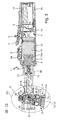
figures 1 and 2 along line III-III offigure 2 ; - Figure 4
- a sectional view of detail IV of
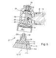
figure 3 ; - Figure 5
- the detail IV shown in
figure 4 with a first embodiment of a functional unit according to the present invention detached from the rest of the power tool; and - Figure 6
- the detail IV shown in
figure 4 with a second embodiment of a functional unit according to the present invention detached from the rest of the power tool. -
Figures 1 and 2 show a side view of a hand held and/or hand guided power tool embodied as a polishing machine or a polisher. The polisher in its entirety is designated withreference sign 1. Alternatively, thepower tool 1 according to the present invention could also be embodied as a sander or a grinder, or even as a drill, a cordless screw driver, a mixer, or an electric saw, only to mention a few examples. - The
polisher 1 comprises a housing 2 made up of essentially two main parts, arear part 2a and afront part 2c. In more detail the housing 2 comprises therear part 2a, adistal end part 2b, thefront part 2c and afront casing 2e. Therear part 2a is preferably made of a rigid plastics material. Of course, therear part 2a of the housing could also be made of a different rigid material, for example metal or carbon fiber. Further, therear part 2a of the housing 2 could comprise regions provided with resilient material like a soft plastic material or rubber in order to ensure safe and comfortable gripping, holding and guiding of thepower tool 1 by a user or operator. Therear part 2a of the housing is preferably divided into two half shells which are attached on one another along an essentially vertical plane and held together byscrews 3. - The
rear part 2a of the housing 2 comprises anactuation lever 4 co-operating with a switch for turning on and off thepolisher 1. Theactuation lever 4 comprises ablocking mechanism 5 for avoiding unintentional activation of thetool 1. Furthermore, therear part 2a of the housing is provided with aturn wheel 6 for speed regulation of a tool's motor. A distalrear end 2b of therear part 2a of the housing can be removed in order to withdraw a battery 14 (seefigure 3 ) from the inside of therear part 2a of the housing 2. Thebattery 14 provides thepolisher 1 and its electronic components, respectively, with electric energy necessary for their operation. Of course, thepolisher 1 could also be operated with electric energy from a mains power supply. In that case abattery 14 would not be necessary and the compartment for the battery could be used for accommodating a transformer and other electric circuitry for transforming the mains voltage from 100V to 250V and from 50Hz to 60Hz, into an operating voltage (e.g. 12V, 18V, or 24V) for the electronic components of thepolisher 1. Thedistal end 2b of the housing 2 is secured to therear part 2a by means of a snap-action connection comprising two oppositelateral knobs 7 for releasing the snap-connection. For removing the distalrear end 2b from therear part 2a of the housing 2, the lateral snap-releasingknobs 7 are pressed, thereby releasing the snap-action connection and allowing separation of thedistal end 2b of the housing 2 from therear part 2a and withdrawal of thebattery 14 from the housing 2. Therear part 2a of the housing 2 is provided with a plurality ofslots 8 enabling an airstream from the inside to the outside of the housing 2 and cooling of the electronic components located inside the housing 2. - Furthermore, located inside the
rear part 2a of the housing 2 is anelectric motor 16, preferably a brushless (BL) motor, in particular a BL direct current (BLDC) motor, with amotor shaft 16a, which actuates afirst gear mechanism 17 which can determine a certain ratio between the rotational speed of themotor shaft 16a and the rotational speed of atool shaft 19 and/or 23, which eventually drives the workingelement 11. Depending on the design of thegear mechanism 17, the ration can be 1, larger than 1 or smaller than 1. Usually, the ratio will be larger than 1 because themotor shaft 16a turns faster than thetool shaft 23. Preferably, thefirst gear mechanism 17 is an epicyclic gear. The gearbox output shaft is designated withreference sign 18. Theoutput shaft 18 is connected to afirst tool shaft 19 by means of acoupling assembly 20. - The
power tool 1 can comprise asecond gear mechanism 24 in order to translate the rotational movement of themotor shaft 16a and of thefirst tool shaft 19, respectively, about a firstrotational axis 22 into a rotational movement of asecond tool shaft 23, which actuates the workingelement 11, about a secondrotational axis 12, whereas the twoaxes rotational axes second gear mechanism 24 can comprise a bevel gear with twobevel gear wheels 26. In contrast to the embodiment offigure 3 the first andsecond gear mechanism tool 1, e.g. in atool head 9. Alternatively, thetool 1 according to the present invention may also comprise only one of the twogear mechanisms control unit 6a is located inside the housing 2. Preferably, thecontrol unit 6a comprises a microcontroller and/or a microprocessor for processing a computer program which is programed to perform the desired motor control function, when it is processed on the microprocessor. - Attached to a front end of the
rear part 2a is thefront part 2c of the housing 2. Thefront part 2c is preferably made of metal or a rigid plastics material. Thefront part 2c can be fixed to therear part 2a of the housing 2 by means of screws or similar attachment means. Of course, thefront part 2c and therear part 2a of the housing 2 could be embodied as a single common housing unit, too. Atool head 9 is fixed to a frontdistal end 2d of thefront part 2c of the housing 2. Thetool head 9 is preferably fixed to thedistal end 2d by means of screws or similar attachment means or by means of a threadedconnection 2f. Thetool head 9 comprises thecasing 2e preferably made of metal or a rigid plastics material. Thetool head 9 further comprises a workingelement 11 and the second gear mechanism 24 (seefigures 3 to 6 ) for translating the rotational movement of themotor shaft 16a and the first tool shaft 19 (seefigure 3 ) into a corresponding rotational movement of thesecond tool shaft 23 about therotational axis 12. - The distal
rear end 2b of therear part 2a of the housing 2 is attached to or forms integral part with abattery pack 13 comprising thebattery 14 and possibly other electric or electronic components. Upon insertion of thebattery pack 13 into therear part 2a of the housing 2 it is automatically connected toelectric connectors 15, fixedly located inside the housing 2. Electric energy stored in thebattery 14 is provided to the other electrical components of thepolisher 1 via theconnectors 15. - The coupling of the
coupling assembly 20 is such that torque is transmitted from thegear output shaft 18 to thefirst tool shaft 19. Thetool shaft 19 is rotably supported in thefront part 2c of the housing 2 by means ofbearings 21 such that it rotates about therotational axis 22. In the shown embodiment therotational axis 22 of thefirst tool shaft 19 is identical to a rotational axis of thegear output shaft 18 of thefirst gear mechanism 17. The rotational movement of theoutput shaft 18 and thefirst tool shaft 19, respectively, is transmitted to asecond tool shaft 23 by means of thesecond gear mechanism 24. Thesecond tool shaft 23 is rotably supported about therotational axis 12 of thetool head 9 by means ofbearings 25. - Attached to the
second tool shaft 23 is afunctional unit 27 according to the present invention, which provides for a functional connection between thesecond tool shaft 23 and the workingelement 11. Thefunctional unit 27 determines the type of actuating movement of the workingelement 11. To this end thefunctional unit 27 comprises acarrier element 28 which holds the workingelement 11. Depending on the type and design of thefunctional unit 27 and thecarrier element 28, respectively, the actuating movement of the workingelement 11 can comprise one or more of the following kind: a purely rotational, a random-orbital, a roto-orbital, a planetary, a linear and a linear or rotary alternating back-and-forth actuating movement. Furthermore, thefunctional unit 27 comprises means for detachably fixing theunit 27 to the rest of thetool 1, e.g. to a distal end of a tool shaft, for instance of thesecond tool shaft 23. Thefunctional unit 27 and its attachment to the rest of thetool 1 are described in more detail with reference tofigures 5 and6 below. - The working
element 11 can comprise abacking plate 11a, which is preferably made of expanded polyurethane and particularly resistant to mechanical stresses. A supportingstructure 11b, for example made of metal or a rigid plastics material, is embedded into the top of thebacking plate 11a. Abottom surface 11c of thebacking plate 11a is provided with attachment means, for example a hook-and-loop-fastener, a glued surface or means for mechanical adhesion, for removably attaching a working sheet, for example apolishing pad 11d made of a foamed material or microfiber, a polishing cushion made of wool or similar material, or an abrasive sheet material. Of course, the workingelement 11 and thebacking plate 11a, respectively, could also be used directly for working a surface of a workpiece, without the need to attach a separate working sheet to thebottom surface 11c. In that case, thebacking plate 11a and thebottom surface 11c could be designed such that they can directly perform a sanding or polishing operation on the workpiece surface or the working sheet could be integrally formed (e.g. by means of a molding process) on or inseparably attached (e.g. glued or welded) to thebottom surface 11c of thebacking plate 11a. - The user or operator of the
tool 1 can replace a working sheet attached to thebottom surface 11c of thebacking plate 11a (leaving the rest of the workingelement 11 attached to the tool 1). Alternatively or additionally the user can also replace the workingelement 11 in its entirety (leaving the rest of thefunctional unit 27 attached to the tool 1). Furthermore, alternatively or additionally the user can also replace thefunctional unit 27 in its entirety comprising the workingelement 11 and, if present, the workingsheet 11d attached thereto. Of course, after replacing thefunctional unit 27 the previously used workingelement 11 and/or workingsheet 11d could be re-attached to the newfunctional unit 27. Preferably, thebevel gear mechanism 24 cannot be replaced by a different gear mechanism. However, theoretically it could be possible to design thetool 1 such that theentire tool head 9 can be replaced, including thegear mechanism 24 and thefunctional unit 27 with the workingelement 11. -
Figure 4 shows a detailed view of section IV offigure 3 comprising thetool head 9 and thefunctional unit 27 performing a purely rotational actuating movement. Thefunctional unit 27 comprising thecarrier element 28 and the workingelement 11 is releasably attached to the distal end of thesecond tool shaft 23 by means of a threadedconnection 29.Figure 5 shows thefunctional unit 27 offigure 4 detached from the rest of thetool 1. Thefunctional unit 27 can be detached from thesecond tool shaft 23 by inhibiting rotation of thetool shaft 23 and contemporaneously rotating thefunctional unit 27 about therotational axis 12, in order to loosen the threadedconnection 29. The rotation of thesecond tool shaft 23 can be inhibited by pressing an appropriate brake orinterference button 36 at the top of thetool head 9. Of course, the means for inhibiting the rotation of thetool shaft 23 can be designed in any other appropriate form and can be located in any other appropriate position. - As can be seen from
figure 5 , the threadedconnection 29 comprises anexternal thread 29a embodied on ashaft 30 of thecarrier element 28. Furthermore, the threadedconnection 29 comprises a secondinternal thread 29b located within abore 31 at a distal end part of thesecond tool shaft 23. Preferably, seen from the bottom of the workingelement 11 or from the top of thetool 1, adirection 34 of the threadedconnection 29 is opposite to adirection 35 of the rotational movement of thesecond tool shaft 23 about therotational axis 12. In the embodiment shown infigure 4 thedirection 35 of the rotational movement of thesecond tool shaft 23 seen from above is clockwise. The threadedconnection 29 would go into the respectiveopposite direction 34, that is seen from above counter-clockwise. This has the advantage that during use of thetool 1, the connection between thefunctional unit 27, 27' and the rest of thetool 1 is automatically fastened and will not loosen unintentionally. Alternatively, thedirection 35 of the rotational movement of theshaft 23 could also be directed counter-clockwise, in which case thedirection 34 of the thread would be clockwise. This allows a transmission of torque at least in thedirection 35 of the rotational movement of thesecond tool shaft 23. Of course, the means for releasably connecting thefunctional unit 27 to the rest of thetool 1, in particular to thesecond tool shaft 23, can be designed in any other appropriate manner, too. - It can be clearly seen from
figure 5 , that thefunctional unit 27 comprises thecarrier element 28 and the workingelement 11. Thecarrier element 28 shown infigure 5 holds the workingelement 11 with a rotational axis 12' of the workingelement 11 congruent with therotational axis 12 of thesecond tool shaft 23. Hence, the workingelement 11 performs a purely rotational actuating movement aroundaxis 12, 12'. With other words, therotational axis 12 is the same for thesecond tool shaft 23, theshaft 30 of thecarrier element 28 and the workingelement 11. To this end thecarrier unit 28 can be attached to the distal end of thetool shaft 23 in a torque proof manner and the workingelement 11 is attached in a torque proof manner to thecarrier unit 28 as well. In the embodiments offigures 1 to 5 the torque proof connections are effected by means of threaded connections comprising externally threaded rods being screwed into bores having corresponding internal threads. - The
functional unit 27 shown infigure 5 can be replaced by another functional unit 27', like the one shown infigure 6 . It can be clearly seen that in the embodiment of the functional unit 27' offigure 6 the rotational axis 12' of the workingelement 11 is not identical to therotational axis 12 of thesecond tool shaft 23. Rather, the tworotational axes 12, 12' run parallel to and spaced apart from one another. Furthermore, the carrier element 28' forms an eccentric set, comprising aneccentric bearing 28a (e.g. one or more ball bearings or a double row ball bearing) and aspindle 33, adapted for receiving the workingelement 11. Thespindle 33 is connected to the supportingmember 11b of the workingelement 11 in a torque proof manner by means of a further threadedconnection 32. Of course, there are many other possibilities for connecting the workingelement 11 to thespindle 33 in a torque proof manner. Thespindle 33 could also be an integral part of the supportingmember 11b of the workingelement 11. Thespindle 33 is held freely rotatable about the rotational axis 12' in the carrier element 28' by means of thebearings 28a. Together, the rotational movement of the eccentric carrier element 28' about therotational axis 12 plus the possibility for thespindle 33 to freely rotate about the rotational axis 12' determine the random orbital actuating movement of the workingelement 11. Hence, the functional unit 27' offigure 6 has a carrier element 28', which translates the rotational movement of thesecond tool shaft 23 about therotational axis 12 into a random orbital actuating movement of the workingelement 11. - Of course, the working
element 11 of the functional unit 27' offigure 6 could perform any other type of actuating movement, too, if the carrier element 28' was designed accordingly. In any case, the actuating movement of the workingelement 11 of the functional unit 27' offigure 6 is different from the actuating movement of the workingelement 11 of thefunctional unit 27 offigure 5 . Hence, thepolisher 1 can perform different types of actuating movements of its workingelement 11 simply by replacing thefunctional unit 27 by another functional unit, like the functional unit 27' offigure 6 . - Each
functional unit 27, 27' can receive different workingelements 11. For example, the functioning unit 27', which performs a random orbital movement, can comprise circular workingelements 11 with diameters of 30mm or 50mm. Similarly, an identical workingelement 11, for example a circular working element with a diameter of 70mm, could be mounted onto thefunctional unit 27 performing the purely rotational movement of the workingelement 11, as well as onto the functional unit 27' defining the random orbital movement.
Claims (16)
- Hand held and/or hand guided power tool (1) comprising a housing (2) with a motor (17) located inside the housing (2) and a working element (11) performing an actuating movement if the tool (1) is actuated, the motor (17) being adapted to actuate a tool shaft (23) in order to make it perform a rotational movement, and the tool (1) further comprising a carrier element (28; 28') functionally located between the tool shaft (23) and the working element (11) for translating the rotational movement of the tool shaft (23) into the actuating movement of the working element (11), characterized in that the working element (11) and the carrier element (28; 28') make part of a functional unit (27; 27') constituting a unit separate from the rest of the tool (1), wherein the functional unit (27; 27') comprises means (29a; 30; 30') for detachably fixing the functional unit (27; 27') to the rest of the tool (1).
- Hand held and/or hand guided power tool (1) according to claim 1, wherein the functional unit (27; 27') is fixed to the rest of the tool (1) by means of a releasable connection, which is torque proof at least in one direction of rotation of the working element (11).
- Hand held and/or hand guided power tool (1) according to claim 1 or 2, wherein the rest of the tool (1) comprises a receiving section to which the functional unit (27; 27') is detachably fixed, wherein said receiving section makes part of the tool shaft (23).
- Hand held and/or hand guided power tool (1) according to claim 3, wherein said receiving section is designed to receive different types of functional units (27; 27') comprising different types of carrier elements (28; 28') and/or working elements (11).
- Hand held and/or hand guided power tool (1) according to one of the preceding claims, wherein the carrier element (28; 28') of the functional unit (27; 27') is detachably fixed to the tool shaft (23) by means of a threaded connection (29) designed such that acceleration of the tool shaft (23) upon activation of the tool (1) fastens the threaded connection (29) and tightens the fixation of the functional unit (27; 27') to the rest of the tool (1).
- Hand held and/or hand guided power tool (1) according to one of the preceding claims, wherein the working element (11) comprises a backing plate (11a) and a working sheet on a bottom surface (11c) of the backing plate (11a), the working sheet adapted for working a surface of a workpiece, wherein the backing plate (11a) is releasably fixed to the rest of the functional unit (27; 27').
- Hand held and/or hand guided power tool (1) according to claim 6, wherein the working sheet is an integral part of the backing plate (11a) or is part of a separate working sheet (11d) releasably fixed to the bottom surface (11c) of the backing plate (11a).
- Hand held and/or hand guided power tool (1) according to claim 6 or 7, wherein the backing plate (11a) is releasably fixed to said carrier element (28; 28') of the functional unit (27; 27') by means of a further threaded connection (32).
- Hand held and/or hand guided power tool (1) according to one of the preceding claims, wherein a plurality of different functional units (27; 27') are available, each of which can be detachably fixed to the rest of the tool (1) and each of which has a carrier element (28; 28') designed such that the working element (11) of the functional unit (27; 27') performs a certain type of actuating movement, the actuating movements of the working elements (11) of the different functional units (27; 27') differing from one another by type and/or degree.
- Hand held and/or hand guided power tool (1) according to claim 9, wherein the differing types of actuating movements performed by the working elements (11) of the different functional units (27; 27') comprise one or more of the following kind: a rotational, a random-orbital, a roto-orbital, a planetary, a linear, a linear or rotary alternating back and forth actuating movement.
- Hand held and/or hand guided power tool (1) according to one of the preceding claims, wherein a plurality of different functional units (27; 27') are available, each of which can be detachably fixed to the rest of the tool (1) and each of which has a working element (11), the working elements (11) of the different functional units (27; 27') differing from one another by type and/or dimension.
- Hand held and/or hand guided power tool (1) according to claim 11, wherein the differing types of working elements (11) of the different functional units (27; 27') comprise one or more of the following kinds of working elements (11): having a backing plate (11a) with a working sheet integrally formed on a bottom surface (11c) of the backing plate (11a), having a backing plate (11a) with an attachment layer on its bottom surface (11c) for releasably attaching separate working sheets (11d), the working sheets being adapted for polishing, sanding, abrading or grinding surfaces of workpieces and/or having backing plates (11a) with different forms, like a delta shape, a rectangular shape or a circular shape, and/or having backing plates (11a) with different dimensions.
- Hand held and/or hand guided power tool (1) according to one of the preceding claims, wherein the tool (1) is one of a polisher, a sander, or a grinder.
- Functional unit (27; 27') of a hand held and/or hand guided power tool (1) according to one of the preceding claims, wherein the tool (1) comprises a housing (2) with a motor (17) located inside the housing (2) and a working element (11) performing an actuating movement if the tool (1) is actuated, and the motor (17) motor (17) is adapted to actuate a tool shaft (23) in order to make it perform a rotational movement, characterized in that the functional unit (27; 27') comprises the working element (11) and a carrier element (28; 28'), which translates the rotational movement of the tool shaft (23) into the actuating movement of the working element (11), wherein the functional unit (27; 27') comprises means (29a; 30; 30') for detachably fixing the functional unit (27; 27') to the rest of the tool (1).
- Functional unit (27; 27') according to claim 14, wherein the means (29a; 30; 30') for fixing the functional unit (27; 27') to the rest of the tool (1) are designed such that they provide a releasable connection, which is torque proof at least in one direction of rotation of the working element (11).
- Functional unit (27; 27') according to claim 14 or 15, wherein the carrier element (28; 28') is detachably fixed to the tool shaft (23) by means of a threaded connection (29) designed such that acceleration of the tool shaft (23) upon activation of the tool (1) fastens the threaded connection (29) and tightens the fixation of the functional unit (27; 27') to the rest of the tool (1).
Priority Applications (3)
| Application Number | Priority Date | Filing Date | Title |
|---|---|---|---|
| EP14190343.5A EP3012068B1 (en) | 2014-10-24 | 2014-10-24 | Hand held and/or hand guided power tool |
| US14/887,399 US9731412B2 (en) | 2014-10-24 | 2015-10-20 | Hand operated power tool |
| CN201510696813.3A CN105538241B (en) | 2014-10-24 | 2015-10-23 | Hand-held and/or hand power tool |
Applications Claiming Priority (1)
| Application Number | Priority Date | Filing Date | Title |
|---|---|---|---|
| EP14190343.5A EP3012068B1 (en) | 2014-10-24 | 2014-10-24 | Hand held and/or hand guided power tool |
Publications (2)
| Publication Number | Publication Date |
|---|---|
| EP3012068A1 true EP3012068A1 (en) | 2016-04-27 |
| EP3012068B1 EP3012068B1 (en) | 2020-06-24 |
Family
ID=51794789
Family Applications (1)
| Application Number | Title | Priority Date | Filing Date |
|---|---|---|---|
| EP14190343.5A Active EP3012068B1 (en) | 2014-10-24 | 2014-10-24 | Hand held and/or hand guided power tool |
Country Status (3)
| Country | Link |
|---|---|
| US (1) | US9731412B2 (en) |
| EP (1) | EP3012068B1 (en) |
| CN (1) | CN105538241B (en) |
Cited By (3)
| Publication number | Priority date | Publication date | Assignee | Title |
|---|---|---|---|---|
| EP3854526A1 (en) | 2020-01-23 | 2021-07-28 | Guido Valentini | Protective shroud for a hand-guided power tool and hand-guided power tool with such a protective shroud |
| EP3854523A1 (en) | 2020-01-23 | 2021-07-28 | Guido Valentini | Functional unit for a hand-guided power tool and power tool with such a functional unit |
| EP3865262A1 (en) * | 2020-02-14 | 2021-08-18 | Andreas Stihl AG & Co. KG | Hand-held processing device with motor housing |
Families Citing this family (15)
| Publication number | Priority date | Publication date | Assignee | Title |
|---|---|---|---|---|
| JP6443541B2 (en) * | 2015-04-24 | 2018-12-26 | 工機ホールディングス株式会社 | Electric tool |
| CN106926096B (en) * | 2015-12-31 | 2020-01-31 | 南京德朔实业有限公司 | Angle grinder |
| EP3476537A4 (en) | 2016-06-28 | 2020-03-11 | Positec Power Tools (Suzhou) Co., Ltd | Sanding machine, operating method thereof and working baseplate disassembly-assembly method |
| US20180009084A1 (en) * | 2016-07-07 | 2018-01-11 | Stone Pro Equipment Company | Abrading Disc |
| US20180161955A1 (en) * | 2016-12-12 | 2018-06-14 | Benjamin Grossman | Random Walk Polishing Machine |
| CN109382735B (en) * | 2017-08-04 | 2022-01-18 | 苏州宝时得电动工具有限公司 | Sanding machine |
| WO2019024941A1 (en) * | 2017-08-04 | 2019-02-07 | 苏州宝时得电动工具有限公司 | Grinding tool, and main component and grinding component thereof |
| WO2019109277A1 (en) * | 2017-12-06 | 2019-06-13 | Husqvarna Ab | Mating interface for a power head configured to operate multiple tool attachments |
| CN209868288U (en) * | 2018-01-15 | 2019-12-31 | 苏州宝时得电动工具有限公司 | Polishing tool |
| US20190217459A1 (en) * | 2018-01-16 | 2019-07-18 | Tti (Macao Commercial Offshore) Limited | Operational data distribution in a power tool |
| JP7212826B2 (en) * | 2018-03-19 | 2023-01-26 | 京セラインダストリアルツールズ株式会社 | Electric tool |
| US20200391338A1 (en) * | 2019-06-14 | 2020-12-17 | Nanjing Chervon Industry Co., Ltd. | Polishing machine |
| USD932267S1 (en) | 2020-05-19 | 2021-10-05 | B&B Blending, Llc | Micro polisher |
| US20220250202A1 (en) * | 2021-02-08 | 2022-08-11 | Benjamin Grossman | Random Walk Polishing Machine |
| USD974869S1 (en) | 2021-03-08 | 2023-01-10 | Photonix Corp | Cutting tool |
Citations (4)
| Publication number | Priority date | Publication date | Assignee | Title |
|---|---|---|---|---|
| US5921854A (en) * | 1993-12-15 | 1999-07-13 | Evensen; Kenneth R. | Method and apparatus for sanding with a rotating roller |
| DE202007015099U1 (en) * | 2007-10-29 | 2008-03-13 | Fütterer, Werner, Dipl.-Ing. | Use extension of angle grinders to angle drills |
| US20100095534A1 (en) * | 2006-06-07 | 2010-04-22 | Albert Saiz | Cutting Tool Adapter for Rotary Power Tools |
| DE102009028572A1 (en) * | 2009-08-17 | 2011-02-24 | Robert Bosch Gmbh | Adapter for e.g. electric machine tool for converting oscillating rotary motion of drive shaft into rotational movement of driven shaft, has adapter part whose direction is interrupted or continued based on direction change of driven shaft |
Family Cites Families (20)
| Publication number | Priority date | Publication date | Assignee | Title |
|---|---|---|---|---|
| GB8407058D0 (en) * | 1984-03-19 | 1984-04-26 | Black & Decker Inc | Attachments for power tools |
| DE4314799C2 (en) * | 1993-05-05 | 1995-04-13 | Fein C & E | Power tool |
| DE4432973B4 (en) | 1994-09-16 | 2009-10-01 | Robert Bosch Gmbh | Electric hand tool with a spindle lock |
| US5564969A (en) * | 1995-02-01 | 1996-10-15 | Cliffield Industries Ltd. | Hand-held polisher |
| DE19504563A1 (en) * | 1995-02-11 | 1996-08-14 | Stihl Maschf Andreas | Axial chuck for disc-shaped tool |
| US5716263A (en) * | 1996-03-08 | 1998-02-10 | Jones; William C. | Device for cleaning, polishing or sanding |
| TW301958U (en) * | 1996-06-15 | 1997-04-01 | zheng-nan Qin | Internal formed socket bearing |
| US5781955A (en) * | 1996-10-11 | 1998-07-21 | Hendricks; Glen J. | Motorized multiple brush assembly |
| US5851142A (en) * | 1997-03-26 | 1998-12-22 | Unisand Incorporated | Combined grinding and polishing tool |
| US5941764A (en) * | 1997-06-19 | 1999-08-24 | Yang; Maw-Chyuan | Shaft-equipped grinder used in a mold-graving device |
| US7001255B2 (en) * | 2004-04-13 | 2006-02-21 | Lisle Corporation | Thermostat gasket cleaner |
| CN100534717C (en) * | 2004-07-08 | 2009-09-02 | 梅塔波沃克有限公司 | Rapid locking device |
| JP2007152479A (en) | 2005-12-02 | 2007-06-21 | Makita Corp | Power tool |
| US7713110B2 (en) * | 2006-09-05 | 2010-05-11 | Dynabrade, Inc. | Locking random orbital dual-action head assembly |
| DE102007018467A1 (en) * | 2007-04-19 | 2008-10-23 | Robert Bosch Gmbh | Motor driven machine tool |
| US8029340B2 (en) * | 2007-04-10 | 2011-10-04 | D.C. Henning, Inc. | Quick mount adapter and backing plate surface care system and apparatus |
| US8475234B2 (en) * | 2009-09-27 | 2013-07-02 | Yen-Ju HO | Power tool holding article |
| US9174354B2 (en) * | 2011-05-18 | 2015-11-03 | Chevron (Hk) Limited | Power tool |
| FR3001169B1 (en) * | 2013-01-24 | 2016-02-12 | Airbus Operations Sas | ASSISTING DEVICE FOR HANDLING A SANDING TOOL |
| CN203409654U (en) * | 2013-05-30 | 2014-01-29 | 常州金智慧工具科技有限公司 | Eccentric polishing machine |
-
2014
- 2014-10-24 EP EP14190343.5A patent/EP3012068B1/en active Active
-
2015
- 2015-10-20 US US14/887,399 patent/US9731412B2/en active Active
- 2015-10-23 CN CN201510696813.3A patent/CN105538241B/en active Active
Patent Citations (4)
| Publication number | Priority date | Publication date | Assignee | Title |
|---|---|---|---|---|
| US5921854A (en) * | 1993-12-15 | 1999-07-13 | Evensen; Kenneth R. | Method and apparatus for sanding with a rotating roller |
| US20100095534A1 (en) * | 2006-06-07 | 2010-04-22 | Albert Saiz | Cutting Tool Adapter for Rotary Power Tools |
| DE202007015099U1 (en) * | 2007-10-29 | 2008-03-13 | Fütterer, Werner, Dipl.-Ing. | Use extension of angle grinders to angle drills |
| DE102009028572A1 (en) * | 2009-08-17 | 2011-02-24 | Robert Bosch Gmbh | Adapter for e.g. electric machine tool for converting oscillating rotary motion of drive shaft into rotational movement of driven shaft, has adapter part whose direction is interrupted or continued based on direction change of driven shaft |
Cited By (4)
| Publication number | Priority date | Publication date | Assignee | Title |
|---|---|---|---|---|
| EP3854526A1 (en) | 2020-01-23 | 2021-07-28 | Guido Valentini | Protective shroud for a hand-guided power tool and hand-guided power tool with such a protective shroud |
| EP3854523A1 (en) | 2020-01-23 | 2021-07-28 | Guido Valentini | Functional unit for a hand-guided power tool and power tool with such a functional unit |
| EP3865262A1 (en) * | 2020-02-14 | 2021-08-18 | Andreas Stihl AG & Co. KG | Hand-held processing device with motor housing |
| US11563351B2 (en) | 2020-02-14 | 2023-01-24 | Andreas Stihl Ag & Co. Kg | Hand-guided treatment device having a motor housing |
Also Published As
| Publication number | Publication date |
|---|---|
| EP3012068B1 (en) | 2020-06-24 |
| CN105538241B (en) | 2018-05-25 |
| US20160121475A1 (en) | 2016-05-05 |
| CN105538241A (en) | 2016-05-04 |
| US9731412B2 (en) | 2017-08-15 |
Similar Documents
| Publication | Publication Date | Title |
|---|---|---|
| EP3012068B1 (en) | Hand held and/or hand guided power tool | |
| CN111546199B (en) | Hand-held and hand-guided random orbital burnishing or sanding power tool | |
| EP3421179A1 (en) | Polishing pad for releasable attachment to a bottom surface of a plate-like backing pad of a power tool, backing pad and hand-held power tool | |
| CN111098209B (en) | Hand-held and hand-guided random track polishing or sanding power tool | |
| US20170312877A1 (en) | Hand held or hand guided grinding or polishing machine tool | |
| US20100197209A1 (en) | Electric hand-held power tool for performing sanding work, in particular a finishing sander | |
| EP2736675B1 (en) | Modular dual-action device | |
| EP2262613B1 (en) | Method, apparatus, and system using adapter assembly for modifying surfaces | |
| CN214519995U (en) | Hand-held and/or manually operated power tool | |
| US20210229232A1 (en) | Functional unit for a hand-guided power tool and power tool with such a functional unit | |
| EP3892419A1 (en) | Double-sided polishing or sanding member for attachment to a hand-guided power tool and power tool with such a polishing or sanding member | |
| US11969850B2 (en) | Hand-held and hand-guided random orbital polishing or sanding power tool | |
| DE202014011331U1 (en) | Portable and / or hand-held motorized tool | |
| EP4063069B1 (en) | Plate-like backing pad adapted for releasable attachment to a hand-held polishing or sanding power tool | |
| GB2420091A (en) | An electrically powered grinding tool | |
| JP3183767U (en) | Electric nail polisher | |
| AT17039U2 (en) | PORTABLE AND/OR HANDHELD MOTORIZED TOOL | |
| KR20120005136U (en) | Grinding device for plastic |
Legal Events
| Date | Code | Title | Description |
|---|---|---|---|
| PUAI | Public reference made under article 153(3) epc to a published international application that has entered the european phase |
Free format text: ORIGINAL CODE: 0009012 |
|
| AK | Designated contracting states |
Kind code of ref document: A1 Designated state(s): AL AT BE BG CH CY CZ DE DK EE ES FI FR GB GR HR HU IE IS IT LI LT LU LV MC MK MT NL NO PL PT RO RS SE SI SK SM TR |
|
| AX | Request for extension of the european patent |
Extension state: BA ME |
|
| 17P | Request for examination filed |
Effective date: 20160930 |
|
| RBV | Designated contracting states (corrected) |
Designated state(s): AL AT BE BG CH CY CZ DE DK EE ES FI FR GB GR HR HU IE IS IT LI LT LU LV MC MK MT NL NO PL PT RO RS SE SI SK SM TR |
|
| STAA | Information on the status of an ep patent application or granted ep patent |
Free format text: STATUS: EXAMINATION IS IN PROGRESS |
|
| 17Q | First examination report despatched |
Effective date: 20180705 |
|
| GRAP | Despatch of communication of intention to grant a patent |
Free format text: ORIGINAL CODE: EPIDOSNIGR1 |
|
| STAA | Information on the status of an ep patent application or granted ep patent |
Free format text: STATUS: GRANT OF PATENT IS INTENDED |
|
| INTG | Intention to grant announced |
Effective date: 20200421 |
|
| GRAS | Grant fee paid |
Free format text: ORIGINAL CODE: EPIDOSNIGR3 |
|
| GRAA | (expected) grant |
Free format text: ORIGINAL CODE: 0009210 |
|
| STAA | Information on the status of an ep patent application or granted ep patent |
Free format text: STATUS: THE PATENT HAS BEEN GRANTED |
|
| AK | Designated contracting states |
Kind code of ref document: B1 Designated state(s): AL AT BE BG CH CY CZ DE DK EE ES FI FR GB GR HR HU IE IS IT LI LT LU LV MC MK MT NL NO PL PT RO RS SE SI SK SM TR |
|
| REG | Reference to a national code |
Ref country code: GB Ref legal event code: FG4D |
|
| REG | Reference to a national code |
Ref country code: CH Ref legal event code: EP |
|
| REG | Reference to a national code |
Ref country code: AT Ref legal event code: REF Ref document number: 1283412 Country of ref document: AT Kind code of ref document: T Effective date: 20200715 |
|
| REG | Reference to a national code |
Ref country code: DE Ref legal event code: R096 Ref document number: 602014066929 Country of ref document: DE |
|
| REG | Reference to a national code |
Ref country code: IE Ref legal event code: FG4D |
|
| PG25 | Lapsed in a contracting state [announced via postgrant information from national office to epo] |
Ref country code: FI Free format text: LAPSE BECAUSE OF FAILURE TO SUBMIT A TRANSLATION OF THE DESCRIPTION OR TO PAY THE FEE WITHIN THE PRESCRIBED TIME-LIMIT Effective date: 20200624 Ref country code: GR Free format text: LAPSE BECAUSE OF FAILURE TO SUBMIT A TRANSLATION OF THE DESCRIPTION OR TO PAY THE FEE WITHIN THE PRESCRIBED TIME-LIMIT Effective date: 20200925 Ref country code: NO Free format text: LAPSE BECAUSE OF FAILURE TO SUBMIT A TRANSLATION OF THE DESCRIPTION OR TO PAY THE FEE WITHIN THE PRESCRIBED TIME-LIMIT Effective date: 20200924 Ref country code: SE Free format text: LAPSE BECAUSE OF FAILURE TO SUBMIT A TRANSLATION OF THE DESCRIPTION OR TO PAY THE FEE WITHIN THE PRESCRIBED TIME-LIMIT Effective date: 20200624 Ref country code: LT Free format text: LAPSE BECAUSE OF FAILURE TO SUBMIT A TRANSLATION OF THE DESCRIPTION OR TO PAY THE FEE WITHIN THE PRESCRIBED TIME-LIMIT Effective date: 20200624 |
|
| REG | Reference to a national code |
Ref country code: LT Ref legal event code: MG4D |
|
| PG25 | Lapsed in a contracting state [announced via postgrant information from national office to epo] |
Ref country code: BG Free format text: LAPSE BECAUSE OF FAILURE TO SUBMIT A TRANSLATION OF THE DESCRIPTION OR TO PAY THE FEE WITHIN THE PRESCRIBED TIME-LIMIT Effective date: 20200924 Ref country code: HR Free format text: LAPSE BECAUSE OF FAILURE TO SUBMIT A TRANSLATION OF THE DESCRIPTION OR TO PAY THE FEE WITHIN THE PRESCRIBED TIME-LIMIT Effective date: 20200624 Ref country code: LV Free format text: LAPSE BECAUSE OF FAILURE TO SUBMIT A TRANSLATION OF THE DESCRIPTION OR TO PAY THE FEE WITHIN THE PRESCRIBED TIME-LIMIT Effective date: 20200624 Ref country code: RS Free format text: LAPSE BECAUSE OF FAILURE TO SUBMIT A TRANSLATION OF THE DESCRIPTION OR TO PAY THE FEE WITHIN THE PRESCRIBED TIME-LIMIT Effective date: 20200624 |
|
| REG | Reference to a national code |
Ref country code: NL Ref legal event code: MP Effective date: 20200624 |
|
| REG | Reference to a national code |
Ref country code: AT Ref legal event code: MK05 Ref document number: 1283412 Country of ref document: AT Kind code of ref document: T Effective date: 20200624 |
|
| PG25 | Lapsed in a contracting state [announced via postgrant information from national office to epo] |
Ref country code: NL Free format text: LAPSE BECAUSE OF FAILURE TO SUBMIT A TRANSLATION OF THE DESCRIPTION OR TO PAY THE FEE WITHIN THE PRESCRIBED TIME-LIMIT Effective date: 20200624 Ref country code: AL Free format text: LAPSE BECAUSE OF FAILURE TO SUBMIT A TRANSLATION OF THE DESCRIPTION OR TO PAY THE FEE WITHIN THE PRESCRIBED TIME-LIMIT Effective date: 20200624 |
|
| PG25 | Lapsed in a contracting state [announced via postgrant information from national office to epo] |
Ref country code: AT Free format text: LAPSE BECAUSE OF FAILURE TO SUBMIT A TRANSLATION OF THE DESCRIPTION OR TO PAY THE FEE WITHIN THE PRESCRIBED TIME-LIMIT Effective date: 20200624 Ref country code: ES Free format text: LAPSE BECAUSE OF FAILURE TO SUBMIT A TRANSLATION OF THE DESCRIPTION OR TO PAY THE FEE WITHIN THE PRESCRIBED TIME-LIMIT Effective date: 20200624 Ref country code: PT Free format text: LAPSE BECAUSE OF FAILURE TO SUBMIT A TRANSLATION OF THE DESCRIPTION OR TO PAY THE FEE WITHIN THE PRESCRIBED TIME-LIMIT Effective date: 20201026 Ref country code: RO Free format text: LAPSE BECAUSE OF FAILURE TO SUBMIT A TRANSLATION OF THE DESCRIPTION OR TO PAY THE FEE WITHIN THE PRESCRIBED TIME-LIMIT Effective date: 20200624 Ref country code: SM Free format text: LAPSE BECAUSE OF FAILURE TO SUBMIT A TRANSLATION OF THE DESCRIPTION OR TO PAY THE FEE WITHIN THE PRESCRIBED TIME-LIMIT Effective date: 20200624 Ref country code: EE Free format text: LAPSE BECAUSE OF FAILURE TO SUBMIT A TRANSLATION OF THE DESCRIPTION OR TO PAY THE FEE WITHIN THE PRESCRIBED TIME-LIMIT Effective date: 20200624 Ref country code: CZ Free format text: LAPSE BECAUSE OF FAILURE TO SUBMIT A TRANSLATION OF THE DESCRIPTION OR TO PAY THE FEE WITHIN THE PRESCRIBED TIME-LIMIT Effective date: 20200624 |
|
| PG25 | Lapsed in a contracting state [announced via postgrant information from national office to epo] |
Ref country code: PL Free format text: LAPSE BECAUSE OF FAILURE TO SUBMIT A TRANSLATION OF THE DESCRIPTION OR TO PAY THE FEE WITHIN THE PRESCRIBED TIME-LIMIT Effective date: 20200624 Ref country code: SK Free format text: LAPSE BECAUSE OF FAILURE TO SUBMIT A TRANSLATION OF THE DESCRIPTION OR TO PAY THE FEE WITHIN THE PRESCRIBED TIME-LIMIT Effective date: 20200624 Ref country code: IS Free format text: LAPSE BECAUSE OF FAILURE TO SUBMIT A TRANSLATION OF THE DESCRIPTION OR TO PAY THE FEE WITHIN THE PRESCRIBED TIME-LIMIT Effective date: 20201024 |
|
| REG | Reference to a national code |
Ref country code: DE Ref legal event code: R097 Ref document number: 602014066929 Country of ref document: DE |
|
| PG25 | Lapsed in a contracting state [announced via postgrant information from national office to epo] |
Ref country code: DK Free format text: LAPSE BECAUSE OF FAILURE TO SUBMIT A TRANSLATION OF THE DESCRIPTION OR TO PAY THE FEE WITHIN THE PRESCRIBED TIME-LIMIT Effective date: 20200624 |
|
| PLBE | No opposition filed within time limit |
Free format text: ORIGINAL CODE: 0009261 |
|
| STAA | Information on the status of an ep patent application or granted ep patent |
Free format text: STATUS: NO OPPOSITION FILED WITHIN TIME LIMIT |
|
| REG | Reference to a national code |
Ref country code: CH Ref legal event code: PL |
|
| 26N | No opposition filed |
Effective date: 20210325 |
|
| PG25 | Lapsed in a contracting state [announced via postgrant information from national office to epo] |
Ref country code: MC Free format text: LAPSE BECAUSE OF FAILURE TO SUBMIT A TRANSLATION OF THE DESCRIPTION OR TO PAY THE FEE WITHIN THE PRESCRIBED TIME-LIMIT Effective date: 20200624 Ref country code: LU Free format text: LAPSE BECAUSE OF NON-PAYMENT OF DUE FEES Effective date: 20201024 |
|
| REG | Reference to a national code |
Ref country code: BE Ref legal event code: MM Effective date: 20201031 |
|
| PG25 | Lapsed in a contracting state [announced via postgrant information from national office to epo] |
Ref country code: CH Free format text: LAPSE BECAUSE OF NON-PAYMENT OF DUE FEES Effective date: 20201031 Ref country code: BE Free format text: LAPSE BECAUSE OF NON-PAYMENT OF DUE FEES Effective date: 20201031 Ref country code: SI Free format text: LAPSE BECAUSE OF FAILURE TO SUBMIT A TRANSLATION OF THE DESCRIPTION OR TO PAY THE FEE WITHIN THE PRESCRIBED TIME-LIMIT Effective date: 20200624 Ref country code: LI Free format text: LAPSE BECAUSE OF NON-PAYMENT OF DUE FEES Effective date: 20201031 |
|
| PG25 | Lapsed in a contracting state [announced via postgrant information from national office to epo] |
Ref country code: IE Free format text: LAPSE BECAUSE OF NON-PAYMENT OF DUE FEES Effective date: 20201024 |
|
| PG25 | Lapsed in a contracting state [announced via postgrant information from national office to epo] |
Ref country code: TR Free format text: LAPSE BECAUSE OF FAILURE TO SUBMIT A TRANSLATION OF THE DESCRIPTION OR TO PAY THE FEE WITHIN THE PRESCRIBED TIME-LIMIT Effective date: 20200624 Ref country code: MT Free format text: LAPSE BECAUSE OF FAILURE TO SUBMIT A TRANSLATION OF THE DESCRIPTION OR TO PAY THE FEE WITHIN THE PRESCRIBED TIME-LIMIT Effective date: 20200624 Ref country code: CY Free format text: LAPSE BECAUSE OF FAILURE TO SUBMIT A TRANSLATION OF THE DESCRIPTION OR TO PAY THE FEE WITHIN THE PRESCRIBED TIME-LIMIT Effective date: 20200624 |
|
| PG25 | Lapsed in a contracting state [announced via postgrant information from national office to epo] |
Ref country code: MK Free format text: LAPSE BECAUSE OF FAILURE TO SUBMIT A TRANSLATION OF THE DESCRIPTION OR TO PAY THE FEE WITHIN THE PRESCRIBED TIME-LIMIT Effective date: 20200624 |
|
| REG | Reference to a national code |
Ref country code: DE Ref legal event code: R039 Ref document number: 602014066929 Country of ref document: DE Ref country code: DE Ref legal event code: R008 Ref document number: 602014066929 Country of ref document: DE |
|
| PGFP | Annual fee paid to national office [announced via postgrant information from national office to epo] |
Ref country code: DE Payment date: 20221019 Year of fee payment: 9 |
|
| REG | Reference to a national code |
Ref country code: DE Ref legal event code: R082 Ref document number: 602014066929 Country of ref document: DE Representative=s name: WOERZ PATENTANWAELTE PARTNERSCHAFTSGESELLSCHAF, DE |
|
| P01 | Opt-out of the competence of the unified patent court (upc) registered |
Effective date: 20230513 |
|
| REG | Reference to a national code |
Ref country code: DE Ref legal event code: R040 Ref document number: 602014066929 Country of ref document: DE |
|
| PGFP | Annual fee paid to national office [announced via postgrant information from national office to epo] |
Ref country code: GB Payment date: 20231025 Year of fee payment: 10 |
|
| PGFP | Annual fee paid to national office [announced via postgrant information from national office to epo] |
Ref country code: IT Payment date: 20231031 Year of fee payment: 10 Ref country code: FR Payment date: 20231023 Year of fee payment: 10 |