EP3031493A1 - Metamaterial phased array for hyperthermia therapy - Google Patents
Metamaterial phased array for hyperthermia therapy Download PDFInfo
- Publication number
- EP3031493A1 EP3031493A1 EP15196078.8A EP15196078A EP3031493A1 EP 3031493 A1 EP3031493 A1 EP 3031493A1 EP 15196078 A EP15196078 A EP 15196078A EP 3031493 A1 EP3031493 A1 EP 3031493A1
- Authority
- EP
- European Patent Office
- Prior art keywords
- metamaterial
- metal layer
- signal
- output
- structures
- Prior art date
- Legal status (The legal status is an assumption and is not a legal conclusion. Google has not performed a legal analysis and makes no representation as to the accuracy of the status listed.)
- Granted
Links
- 238000009217 hyperthermia therapy Methods 0.000 title claims abstract description 10
- 230000005855 radiation Effects 0.000 claims abstract description 30
- 230000004044 response Effects 0.000 claims abstract description 12
- 230000001066 destructive effect Effects 0.000 claims abstract description 10
- 230000005670 electromagnetic radiation Effects 0.000 claims abstract description 5
- 239000002184 metal Substances 0.000 claims description 95
- 229910052751 metal Inorganic materials 0.000 claims description 95
- 239000003990 capacitor Substances 0.000 claims description 74
- 238000000034 method Methods 0.000 claims description 13
- 230000008859 change Effects 0.000 claims description 8
- 239000000523 sample Substances 0.000 claims description 5
- 230000000644 propagated effect Effects 0.000 claims description 2
- 230000001902 propagating effect Effects 0.000 claims 1
- 230000002093 peripheral effect Effects 0.000 description 24
- 239000010953 base metal Substances 0.000 description 18
- 238000012545 processing Methods 0.000 description 13
- 238000010586 diagram Methods 0.000 description 11
- 238000003384 imaging method Methods 0.000 description 9
- 238000001514 detection method Methods 0.000 description 8
- 206010028980 Neoplasm Diseases 0.000 description 7
- 238000011282 treatment Methods 0.000 description 7
- 239000000463 material Substances 0.000 description 6
- 238000004519 manufacturing process Methods 0.000 description 5
- 206010020843 Hyperthermia Diseases 0.000 description 4
- 230000004907 flux Effects 0.000 description 4
- 230000036031 hyperthermia Effects 0.000 description 4
- 239000000203 mixture Substances 0.000 description 4
- -1 Polytetrafluoroethylene Polymers 0.000 description 3
- 238000013459 approach Methods 0.000 description 3
- 201000011510 cancer Diseases 0.000 description 3
- 239000002131 composite material Substances 0.000 description 3
- 239000003989 dielectric material Substances 0.000 description 3
- 230000000694 effects Effects 0.000 description 3
- 230000010363 phase shift Effects 0.000 description 3
- 238000002560 therapeutic procedure Methods 0.000 description 3
- RYGMFSIKBFXOCR-UHFFFAOYSA-N Copper Chemical compound [Cu] RYGMFSIKBFXOCR-UHFFFAOYSA-N 0.000 description 2
- 229910052802 copper Inorganic materials 0.000 description 2
- 239000010949 copper Substances 0.000 description 2
- 238000007667 floating Methods 0.000 description 2
- 229920001343 polytetrafluoroethylene Polymers 0.000 description 2
- 239000004810 polytetrafluoroethylene Substances 0.000 description 2
- 238000007493 shaping process Methods 0.000 description 2
- 229910000679 solder Inorganic materials 0.000 description 2
- 239000007787 solid Substances 0.000 description 2
- 206010038111 Recurrent cancer Diseases 0.000 description 1
- 238000010521 absorption reaction Methods 0.000 description 1
- 239000000853 adhesive Substances 0.000 description 1
- 230000001070 adhesive effect Effects 0.000 description 1
- 238000003491 array Methods 0.000 description 1
- 230000009286 beneficial effect Effects 0.000 description 1
- 229940044683 chemotherapy drug Drugs 0.000 description 1
- 238000010276 construction Methods 0.000 description 1
- 238000007796 conventional method Methods 0.000 description 1
- 238000005516 engineering process Methods 0.000 description 1
- 230000002708 enhancing effect Effects 0.000 description 1
- 238000005530 etching Methods 0.000 description 1
- 230000007274 generation of a signal involved in cell-cell signaling Effects 0.000 description 1
- 150000002739 metals Chemical class 0.000 description 1
- 238000012986 modification Methods 0.000 description 1
- 230000004048 modification Effects 0.000 description 1
- 239000003607 modifier Substances 0.000 description 1
- 230000010355 oscillation Effects 0.000 description 1
- 230000008569 process Effects 0.000 description 1
- 238000001959 radiotherapy Methods 0.000 description 1
- 230000008054 signal transmission Effects 0.000 description 1
- 238000010408 sweeping Methods 0.000 description 1
- 230000001225 therapeutic effect Effects 0.000 description 1
Images


Classifications
-
- A—HUMAN NECESSITIES
- A61—MEDICAL OR VETERINARY SCIENCE; HYGIENE
- A61N—ELECTROTHERAPY; MAGNETOTHERAPY; RADIATION THERAPY; ULTRASOUND THERAPY
- A61N1/00—Electrotherapy; Circuits therefor
- A61N1/40—Applying electric fields by inductive or capacitive coupling ; Applying radio-frequency signals
- A61N1/403—Applying electric fields by inductive or capacitive coupling ; Applying radio-frequency signals for thermotherapy, e.g. hyperthermia
-
- A—HUMAN NECESSITIES
- A61—MEDICAL OR VETERINARY SCIENCE; HYGIENE
- A61N—ELECTROTHERAPY; MAGNETOTHERAPY; RADIATION THERAPY; ULTRASOUND THERAPY
- A61N5/00—Radiation therapy
- A61N5/02—Radiation therapy using microwaves
- A61N5/022—Apparatus adapted for a specific treatment
- A61N5/025—Warming the body, e.g. hyperthermia treatment
-
- A—HUMAN NECESSITIES
- A61—MEDICAL OR VETERINARY SCIENCE; HYGIENE
- A61N—ELECTROTHERAPY; MAGNETOTHERAPY; RADIATION THERAPY; ULTRASOUND THERAPY
- A61N5/00—Radiation therapy
- A61N5/02—Radiation therapy using microwaves
- A61N5/04—Radiators for near-field treatment
-
- H—ELECTRICITY
- H01—ELECTRIC ELEMENTS
- H01Q—ANTENNAS, i.e. RADIO AERIALS
- H01Q15/00—Devices for reflection, refraction, diffraction or polarisation of waves radiated from an antenna, e.g. quasi-optical devices
- H01Q15/0006—Devices acting selectively as reflecting surface, as diffracting or as refracting device, e.g. frequency filtering or angular spatial filtering devices
- H01Q15/0086—Devices acting selectively as reflecting surface, as diffracting or as refracting device, e.g. frequency filtering or angular spatial filtering devices said selective devices having materials with a synthesized negative refractive index, e.g. metamaterials or left-handed materials
-
- H—ELECTRICITY
- H01—ELECTRIC ELEMENTS
- H01Q—ANTENNAS, i.e. RADIO AERIALS
- H01Q21/00—Antenna arrays or systems
- H01Q21/06—Arrays of individually energised antenna units similarly polarised and spaced apart
- H01Q21/061—Two dimensional planar arrays
- H01Q21/065—Patch antenna array
-
- H—ELECTRICITY
- H01—ELECTRIC ELEMENTS
- H01Q—ANTENNAS, i.e. RADIO AERIALS
- H01Q21/00—Antenna arrays or systems
- H01Q21/06—Arrays of individually energised antenna units similarly polarised and spaced apart
- H01Q21/08—Arrays of individually energised antenna units similarly polarised and spaced apart the units being spaced along or adjacent to a rectilinear path
-
- H—ELECTRICITY
- H01—ELECTRIC ELEMENTS
- H01Q—ANTENNAS, i.e. RADIO AERIALS
- H01Q3/00—Arrangements for changing or varying the orientation or the shape of the directional pattern of the waves radiated from an antenna or antenna system
- H01Q3/44—Arrangements for changing or varying the orientation or the shape of the directional pattern of the waves radiated from an antenna or antenna system varying the electric or magnetic characteristics of reflecting, refracting, or diffracting devices associated with the radiating element
- H01Q3/46—Active lenses or reflecting arrays
-
- A—HUMAN NECESSITIES
- A61—MEDICAL OR VETERINARY SCIENCE; HYGIENE
- A61N—ELECTROTHERAPY; MAGNETOTHERAPY; RADIATION THERAPY; ULTRASOUND THERAPY
- A61N5/00—Radiation therapy
- A61N5/02—Radiation therapy using microwaves
- A61N2005/027—Radiation therapy using microwaves using a phased array
-
- H—ELECTRICITY
- H01—ELECTRIC ELEMENTS
- H01Q—ANTENNAS, i.e. RADIO AERIALS
- H01Q3/00—Arrangements for changing or varying the orientation or the shape of the directional pattern of the waves radiated from an antenna or antenna system
- H01Q3/26—Arrangements for changing or varying the orientation or the shape of the directional pattern of the waves radiated from an antenna or antenna system varying the relative phase or relative amplitude of energisation between two or more active radiating elements; varying the distribution of energy across a radiating aperture
- H01Q3/30—Arrangements for changing or varying the orientation or the shape of the directional pattern of the waves radiated from an antenna or antenna system varying the relative phase or relative amplitude of energisation between two or more active radiating elements; varying the distribution of energy across a radiating aperture varying the relative phase between the radiating elements of an array
- H01Q3/34—Arrangements for changing or varying the orientation or the shape of the directional pattern of the waves radiated from an antenna or antenna system varying the relative phase or relative amplitude of energisation between two or more active radiating elements; varying the distribution of energy across a radiating aperture varying the relative phase between the radiating elements of an array by electrical means
- H01Q3/36—Arrangements for changing or varying the orientation or the shape of the directional pattern of the waves radiated from an antenna or antenna system varying the relative phase or relative amplitude of energisation between two or more active radiating elements; varying the distribution of energy across a radiating aperture varying the relative phase between the radiating elements of an array by electrical means with variable phase-shifters
Definitions
- This disclosure relates generally to hyperthermia therapy systems and methods pertaining to such systems.
- Hyperthermia therapy is a type of medical treatment in which body tissue is exposed to slightly higher temperatures (e.g. greater than about 100 F) to damage and kill cancer cells. Hyperthermia therapy helps make cancer cells more vulnerable to the effects of other treatments, like radiation therapy and certain chemotherapy drugs. Hyperthermia therapy is a promising treatment option for patients with advanced or recurrent cancer.
- Some embodiments are directed to a device having a phase shifting element array including a plurality of metamaterial structures that resonate in response to an input electromagnetic (EM) signal.
- the phase shifting element array generates an output EM signal that is a sum of component output electromagnetic signals generated respectively by the metamaterial structures and is configured to propagate wirelessly through at least a portion of a patient's body.
- the device includes a control circuit configured to control one or both of phases and amplitudes of the component electromagnetic output signals so that at least one of constructive and destructive interference between the component output electromagnetic signals causes the output signal to have a higher intensity EM radiation at a target region interior to the body and to have a zero or low intensity radiation at a non-target region interior to the body.
- the higher intensity EM radiation generates a tissue temperature suitable for hyperthermia therapy at the target region.
- the tissue temperature at the target region may be in in range of about 40 C to 50 C.
- the control circuit can be configured to control at least one of position, focus, and intensity of the higher intensity EM radiation at the target region.
- control circuit includes variable capacitors electrically coupled respectively to the metamaterial structures so that a change in capacitance of one of the variable capacitors changes a phase of a component output signal of an associated metamaterial structure.
- the control circuit includes a signal generator configured to generate control signals that control capacitances of the variable capacitors.
- the input EM signal may propagate to the array of metamaterial structures through a wire probe antenna and/or through a waveguide.
- each metamaterial structure includes a first metal layer structure, an electrically isolated second metal layer structure, and a dielectric layer disposed between the first and second metal structures.
- the first and second metal layer structures are cooperatively configured such that the metamaterial structure resonates at a frequency of the input EM signal at a fixed capacitance.
- the first metal layer structure may be disposed on an upper dielectric surface of the dielectric layer.
- the metamaterial structure may further include a third metal layer structure disposed on the upper dielectric surface and spaced apart from the first metal layer structure.
- a variable capacitor has a first terminal electrically coupled to the first metal layer structure and a second terminal electrically coupled to the third metal layer structure.
- the first metal layer structure is disposed on an upper dielectric surface of the dielectric layer.
- the metamaterial structure further comprises a third metal layer structure disposed on the upper dielectric surface and spaced apart from the first metal layer structure.
- a second metamaterial structure comprises a fourth metal layer structure disposed on a lower dielectric surface and is spaced apart from the second metal layer structure.
- a second variable capacitor has a first terminal electrically coupled to the second metal layer structure and a second terminal electrically coupled to the fourth metal layer structure.
- the metamaterial structure on the upper dielectric surface may be a mirror image of the metamaterial structure on the lower dielectric surface.
- the first metal layer structure comprises a patterned planar structure defining one or more open regions.
- the first metal layer structure can include a peripheral frame portion including an outer peripheral edge, one or more radial arms, each radial arm having a first end integrally connected to the peripheral frame portion and extending inward from the peripheral frame portion toward a central region of the metamaterial structure, and an inner structure integrally connected to second ends of the one or more radial arms, the inner structure being spaced from the peripheral frame portion.
- control signal is configured to control the component EM output signals to scan the output signal across a detection area.
- the control circuit may be configured to generate beam direction data indicating instantaneous scan direction of the output signal.
- the device can include a detector circuit configured to detect a portion of the output signal reflected from a structure interior to the body and a signal processing circuit configured to combine the scan direction and the reflected portion of the output signal and to provide information about the structure.
- the information may comprise one or more of presence, size, location, and image information.
- An output EM signal is generated that is a sum of component output electromagnetic signals generated respectively by a plurality of metamaterial structures that resonate in response to an input electromagnetic (EM) signal.
- the output EM is propagated wirelessly through at least a portion of a patient's body.
- One or both of phases and amplitudes of the component electromagnetic output signals are controlled so that at least one of constructive and destructive interference between the component output electromagnetic signals causes the output signal to have a higher intensity EM radiation at a target region interior to the body and to have a zero or low intensity radiation at a non-target region interior to the body.
- the higher intensity electromagnetic radiation generates a tissue temperature suitable for hyperthermia therapy at the target region.
- the method further includes controlling the component electromagnetic output signals to scan the output signal across a detection area.
- Beam direction data is generated that indicates instantaneous scan direction of the output signal.
- a portion of the output signal reflected from a structure interior to the body is detected.
- the scan direction and the reflected portion of the output signal are combined to provide information about the structure.
- a device includes a phase shifting element array comprising a plurality of metamaterial structures that resonate in response to an input electromagnetic (EM) signal.
- the phase shifting element array generates an output EM signal that is a sum of component output electromagnetic signals generated respectively by the metamaterial structures.
- the output EM signal is configured to propagate wirelessly through at least a portion of a patient's body.
- a control circuit is configured to control one or both of phases and amplitudes of the component electromagnetic output signals so that at least one of constructive and destructive interference between the component output electromagnetic signals causes the output signal to scan the output signal across a detection area.
- the control circuit generates beam direction data indicating instantaneous scan direction of the output signal.
- a detector circuit detects a portion of the output signal reflected from a structure interior to the body.
- a signal processing circuit combines the scan direction and the reflected portion of the output signal and to provide information about the structure.
- Embodiments described herein involve a treatment and/or imaging system useful for tumor treatment and/or detection.
- the system is based on a phase shifting array that selectively provides electromagnetic radiation to a target region within the patient's body.
- the phase shifting array includes a plurality of metamaterial structures that resonate in response to an input electromagnetic (EM) signal.
- EM electromagnetic
- the phase shifting element array generates an output EM signal that is the combination of component output electromagnetic signals generated respectively by each of the metamaterial structures.
- the output signal is configured to propagate wirelessly through at least a portion of a patient's body.
- a control circuit controls one or both of phases and amplitudes of the component electromagnetic output signals so that at least one of constructive and destructive interference between the component output electromagnetic signals causes the output signal to have a higher intensity EM radiation at a target region interior to the body and to have a zero or low intensity radiation at a non-target region interior to the body.
- the higher intensity EM radiation generates a specified amount of heat flux the target region, thus providing noninvasive hyperthermia treatment within the patient's body.
- the system may be configured to control the phases of the respective component output signals so that the output signal can be caused to scan or "sweep" an area or region into which the output signal is directed.
- the control circuit generates scan direction data that includes the instantaneous scan direction of the output signal.
- the system includes a receiver circuit configured to detect a portion of the output signal that is reflected from one or more structures interior to the body. Signal processing circuit combines the scan direction and the detected portion of the output signal to provide information about presence and location of the structures.
- FIG. 1A is a schematic diagram of a system 160 in accordance with some embodiments.
- FIG. 1A depicts an input source 161 that provides an input electromagnetic (EM) radiation signal to a phase shifting array 162.
- a control circuit 163 is coupled to control the phase shifting array 162 and is optionally coupled to control the input source. According to various implementations, the control circuit 163 may be capable of controlling one or more of the phase of each component output signal, the amplitude of each component output signal, the frequency of the input signal and the amplitude of the input signal.
- the input source 161 includes a signal generator 161a such as an oscillator, coupled to a power amplifier 161b that boosts the input signal.
- the input source 161 may produce a continuous wave (CW) voltage oscillating sinusoidally at a specified microwave frequency, e.g., 3 kHz to 300 GHz or in some implementations about 915 MHz.
- the input signal can be transmitted to the phase shifting array through an antenna and/or waveguide 161c, e.g., a wire probe antenna disposed within a metal waveguide structure that causes the input signal to be incident on the phased array as described in more detail below.
- the phased array 162 is configured to provide beam shaping and beam forming of the output signal beam due to constructive and/or destructive interference between the component output electromagnetic signals.
- the beam forming/beam shaping causes the output beam 166a to have a higher intensity EM radiation at a target region 164a interior to the patient's body 164 and to have a zero or low intensity radiation at a non-target region 164b interior to the patient's body 164.
- the higher intensity EM radiation can be controlled to a specified amount of heat flux the target region 164a to provide noninvasive hyperthermia treatment within the patient's body.
- multiple phased arrays 162a, 162b may be used to produce multiple output beams 166a, 166b.
- a first output signal beam 166a may be substantially orthogonal to a second output signal beam 166b.
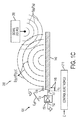
- FIG. 1B shows a phased array 162 positioned relative to a patient with control lines 163a and waveguides 161c visible.
- FIG. 1C is a simplified side view showing a system 200 including at least one metamaterial-based phase shifting element 100 according to a generalized exemplary embodiment.
- Phase shifting element 100 utilizes a metamaterial structure 140 to produce an output signal S OUT having the same radio wave frequency as that of an applied/received input signal S IN , and utilizes a variable capacitor 150 to control a phase p OUT of output signal S OUT by way of an applied phase control signal (e.g., either an externally supplied digital signal C or a direct-current control voltage Vc).
- an applied phase control signal e.g., either an externally supplied digital signal C or a direct-current control voltage Vc.
- System 200 also includes a portion of a signal source 205 (e.g., a feed horn or a leaky-wave feed) disposed in close proximity to phase shifting element 100 and configured to generate input signal S IN at a particular radio wave frequency (e.g., in the range of 3 kHz to 300 GHz) and an input phase p IN , where the radio wave frequency matches resonance characteristics of phase shifting element 100, and a control circuit 210 (e.g., including a digital-to-analog converter (DAC) that is controlled by any of a field programmable gate array (FPGA), an application specific integrated circuit (ASIC, or a micro-processor) that is configured to generate phase control voltages Vc applied to variable capacitor 150 at voltage levels determined in accordance with (e.g., directly or indirectly proportional to) a preprogrammed signal generation scheme or an externally supplied phase control signal C.
- a signal source 205 e.g., a feed horn or a leaky-wave feed
- a control circuit 210
- Metamaterial structure 140 is preferably a layered metal-dielectric composite architecture, but may be engineered in a different form, provided the resulting structure is configured to resonate at the radio frequency of applied input signal S IN , and has a large phase swing near resonance such that metamaterial structure 140 generates output signal S OUT at the input signal frequency by retransmitting (e.g., reflecting/scattering) input signal S IN .
- metamaterial structure 140 is produced with an inherent "fixed" capacitance C M and an associated inductance that collectively provide the desired resonance characteristics.
- the term "metamaterial” identifies an artificially engineered structure formed by two or more materials and multiple elements that collectively generate desired electromagnetic properties, where metamaterial achieves the desired properties not from its composition, but from the exactingly-designed configuration (e.g., the precise shape, geometry, size, orientation and arrangement) of the structural elements formed by the materials.
- the phrase "metamaterial structure” is intended to mean a dynamically reconfigurable/tunable metamaterial having radio frequency resonance and large phase swing properties suitable for the purpose set forth herein. The resulting structure affects radio frequency (electromagnetic radiation) waves in an unconventional manner, creating material properties which are unachievable with conventional materials.
- Metamaterial structures achieve their desired effects by incorporating structural elements of sub-wavelength sizes (having a period of ⁇ /2 or less), e.g. features that are actually smaller than the radio frequency wavelength of the waves they affect.
- metamaterial structure 140 is constructed using inexpensive metal film or PCB fabrication technology that is tailored by solving Maxwell's equations to resonate at the radio frequency of applied input signal S IN , whereby the metamaterial structure 140 generates output signal S OUT at the input signal frequency by retransmitting (e.g., reflecting/scattering) the input signal S IN .
- Variable capacitor 150 is connected between metamaterial structure 140 and ground (or other fixed direct-current (DC) voltage supply).
- variable capacitors are typically two-terminal electronic devices configured to produce a capacitance that is intentionally and repeatedly changeable by way of an applied electronic control signal.
- variable capacitor 150 is coupled to metamaterial structure 140 such that an effective capacitance C eff of metamaterial structure 140 is determined by a product of inherent capacitance C M and a variable capacitance Cv supplied by variable capacitor 150.
- the output phase of metamaterial structure 140 is determined in part by effective capacitance C eff , so output phase p OUT of output signal S OUT is "tunable" (adjustably controllable) to a desired phase value by way of changing variable capacitance Cv, and this is achieved by way of changing the phase control signal (e.g., digital control signal C and/or DC bias voltage Vc) applied to variable capacitor 150.
- phase control signal e.g., digital control signal C and/or DC bias voltage Vc
- FIG. 2 is a diagram showing exemplary phase shifting characteristics associated with operation of phase shifting apparatus 200.
- FIG. 2 shows how output phase p OUT of output signal S OUT changes in relation to phase control voltage Vc.
- FIG. 2 also effectively depicts operating characteristics of variable capacitor 150 (e.g., FIG. 2 effectively illustrates that variable capacitance Cv varies in accordance with phase control voltage Vc by way of showing how output phase p OUT varies in accordance with phase control voltage Vc).
- phase control voltage Vc is applied across variable capacitor 150 by way of a conductive structure 145 that is connected either to metamaterial structure 140 or directly to a terminal of variable capacitor 150.
- variable capacitor 150 includes a first terminal 151 connected to metamaterial structure 140 and a second terminal 152 connected to ground.
- conductive structure 145 is either connected to metamaterial structure 140 or to first terminal 151 of variable capacitor 150 such that, when phase control voltage Vc is applied to conductive structure 145, variable capacitor 150 generates an associated variable capacitance Cv having a capacitance level that varies in accordance with the voltage level of phase control voltage Vc in the manner illustrated in FIG. 2 (e.g., the capacitance level of variable capacitance Cv changes in direct proportion to phase control voltage Vc).
- variable capacitor 150 represents the presently preferred embodiment for generating variable capacitance Cv, those skilled in the art will recognize that other circuits may be utilized to generate a variable capacitance that controls effective capacitance C eff of metamaterial structure 140 in a manner similar to that described herein.
- the novel methodology is alternatively described as including: causing metamaterial structure 140 to resonate at the radio wave frequency of input signal S IN ; applying a variable capacitance Cv (e.g., from any suitable variable capacitance source circuit) to metamaterial structure 140 such that effective capacitance C eff of metamaterial structure 140 is altered by variable capacitance Cv; and adjusting variable capacitance Cv (e.g., by way of controlling the suitable variable capacitance source circuit) until effective capacitance C eff of metamaterial structure 140 has a capacitance value that causes metamaterial structure 140 to generate radio frequency output signal S OUT with output phase p OUT set at a desired phase value (e.g., 290°).
- a desired phase value e.g., 290°
- FIGS. 3A and 3B are exploded perspective and assembled perspective views, respectively, showing a phase shifting element 100A including a two-terminal variable capacitor 150A and a metamaterial structure 140A having an exemplary three-level embodiment.
- FIG. 4 shows a phase shifting apparatus 200A including phase shifting element 100A in cross-sectional side view.
- Beneficial features and aspects of the three-layer structure used to form metamaterial structure 140A, and their usefulness in forming metamaterial-based phase shifting element 100A and apparatus 200A, are described below with reference to FIGS. 3A , 3B and 4 .
- three-layer metamaterial structure 140A is formed by an upper/first metal layer (island) structure 141A, an electrically isolated (e.g., floating) backplane (lower/second metal) layer structure 142A, and a dielectric layer 144A-1 sandwiched between upper island structure 141A and backplane layer 142A, where island structure 141A and backplane layer 142A are cooperatively tailored (e.g., sized, shaped and spaced by way of dielectric layer 144A-1) such that the composite three-layer structure of metamaterial structure 140A has an inherent (fixed) capacitance C M that is at least partially formed by capacitance C 141-142 (e.g., the capacitance between island structure 141A and backplane layer 142A), and such that metamaterial structure 140A resonates at a predetermined radio wave frequency (e.g., 2.4GHz).
- a predetermined radio wave frequency e.g., 2.4GHz
- an effective capacitance of metamaterial structure 140A is generated as a combination of fixed capacitance C M and an applied variable capacitance, which in this case is applied to island structure 141A by way of variable capacitor 150A.
- island structure 141A acts as a wavefront reshaper, which ensures that the output signal S OUT is directed in the upward direction only (e.g., such that the radio frequency output signal is emitted from island structure 141A in a direction away from backplane layer 142A), and which minimizes power consumption because of efficient scattering with phase shift.
- dielectric layer 144A-1 comprises a lossless dielectric material.
- the dielectric material can comprise RT/duroid® 6202 Laminates, Polytetrafluoroethylene (PTFE), and TMM4® dielectric, all produced by Rogers Corporation of Rogers, CT.
- PTFE Polytetrafluoroethylene
- TMM4® dielectric all produced by Rogers Corporation of Rogers, CT.
- the use of such lossless dielectric materials mitigates absorption of incident radiation (e.g., input signal S IN ), and ensures that most of the incident radiation energy is re-emitted in output signal S OUT .
- An optional lower dielectric layer 144A-2 is provided to further isolate backplane layer 142A, and to facilitate the backside mounting of control circuits in the manner described below.
- both island (first metal layer) structure 141A and a base (third) metal layer structure 120A are disposed on an upper surface 144A-1A of dielectric layer 141A-1, where base metal structure 120A is spaced from (e.g., electrically separated by way of a gap G) island structure 141A.
- Metal layer structure 120A is connected to a ground potential during operation, base, whereby base layer structure 120A facilitates low-cost mounting of variable capacitor 150A during manufacturing.
- variable capacitor 150A is mounted such that first terminal 151A is connected (e.g., by way of solder or solderless connection techniques) to island structure 141A, and such that second terminal 152A is similarly connected to base metal structure 120A.
- base metal structure 120A comprises a metal film or PCB fabrication layer that entirely covers upper dielectric surface 144A-1A except for the region defined by an opening 123A, which is disposed inside an inner peripheral edge 124A, where island structure 141A is disposed inside opening 123A such that an outer peripheral edge 141A-1 of is structure 141A is separated from inner peripheral edge 124A by peripheral gap G, which has a fixed gap distance around the entire periphery.
- base metal layer 120A forms a scattering surface that supports collective mode oscillations, and ensures scattering of the wave in the forward direction.
- island structure 141A, backplane layer 142A and base metal structure 120A are cooperatively configured (e.g., sized, shaped and spaced) such that inherent (fixed) capacitance C M includes both the island-backplane component C 141-142 and an island-base component C 141-120 , and such that metamaterial structure 140A resonates at the desired radio wave frequency.
- base metal layer 120A provides the further purpose of effectively forming part of metamaterial structure 140A by enhancing fixed capacitance C M .
- both base (third) metal layer structure 120A and island (first metal layer) structure 141A comprise a single metal (e.g., both base metal structure 120A and island structure 141A comprise the same, identical metal composition, e.g., copper).
- This single-metal feature facilitates the use of low-cost manufacturing techniques in which a single metal film or PCB fabrication is deposited on upper dielectric layer 144A-1A, and then etched to define peripheral gap G.
- different metals may be patterned to form the different structures.
- a metal via structure 145A is formed using conventional techniques such that it extends through lower dielectric layer 144A-2, through an opening 143A defined in backplane layer 142A, through upper dielectric layer 144A-1, and through an optional hole H formed in island structure 141A to contact first terminal 151A of variable capacitor 150A.
- This via structure approach facilitates applying phase control voltages to variable capacitor 150A without significantly affecting the electrical characteristics of metamaterial structure 140A. As set forth below, this approach also simplifies the task of distributing multiple control signals to multiple metamaterial structures forming a phased array.
- FIG. 4 is a cross-sectional side view showing a phase shifting apparatus 200A generating output signal S OUT at an output phase p OUT determined an externally-supplied phase control signal C.
- Apparatus 200A includes a signal source 205A, phase shifting element 100A, and a control circuit 210A.
- Signal source 205A includes a suitable signal generator (e.g., a feed horn) that generates an input signal S IN at a specific radio wave frequency (e.g., 2.4GHz), and is positioned such that input signal S IN is directed onto phase shifting element 100A, which is constructed as described above to resonate at the specific radio wave frequency (e.g., 2.4GHz) such that it generates an output signal S OUT .
- a suitable signal generator e.g., a feed horn
- Control circuit 210A is configured to generate a phase control voltage Vc in response to phase control signal C such that phase control voltage Vc changes in response to changes in phase control signal C.
- Phase control voltage Vc is transmitted to variable capacitor 150A, causing variable capacitor 150A to generate and apply a corresponding variable capacitance onto island structure 141A, whereby metamaterial structure 140A is caused to generate output signal S OUT at an output phase p OUT determined by phase control signal C.
- control circuit 210A is mounted below dielectric layer 144A-2 (e.g., below backplane layer 142A), and phase control voltage Vc is transmitted by way of conductive via structure via 145A to terminal 151A of variable capacitor 150A.
- metamaterial structure 140A is formed such that inner peripheral edge 124A surrounding opening 123A in base metal structure 120A and outer peripheral edge 141A-1 of island structure 141A comprise concentric square shapes such that a width of peripheral gap G remains substantially constant around the entire perimeter of island structure 141A.
- metamaterial structures are formed using shapes other than squares (e.g., round, triangular, rectangular/oblong).
- FIG. 3C shows a phase shifting element 100F that includes a first metamaterial structure 140F, a second metamaterial structure 140F', and a two-terminal variable capacitor 150F'.
- the second metamaterial structure 140F' is a mirror image of the first metamaterial structure 140F.
- the metal structure at the top of FIG. 3C (elements 120F and 141F) is the same or similar to the metal structure at the top of FIG. 3C (elements 142F and 141F').
- the first and second metamaterial structures may comprise patterned layers, e.g., as depicted in FIG. 5 .
- First metamaterial structure 140F is formed by an upper/first metal layer (island) structure 141F, a second metal layer structure 142F, and a dielectric layer 144F sandwiched between the first metal layer (island) structure 141F and second metal layer 142F.
- Both the first metal layer (island) structure 141F and the third metal layer structure 120F are disposed on an upper surface 144F-1 of dielectric layer 144F, where the third metal layer structure 120F is spaced from (e.g., electrically separated by way of a gap) first metal layer (island) structure 141F.
- Third metal layer structure 120F may be connected to a ground potential during operation.
- Both the fourth metal layer (island) structure 141F' and a second metal layer structure 142F are disposed on a lower surface 144F-2 of dielectric layer 144F, where second metal layer structure 142F is spaced from (e.g., electrically separated by way of a gap) fourth metal layer (island) structure 141F'.
- Second metal layer structure 142F may be connected to a ground potential during operation.
- Variable capacitor 150F' is mounted such that the first terminal of variable capacitor 150F' is connected (e.g., by way of solder or solderless connection techniques) to fourth metal layer (island) structure 141F', and the second terminal of variable capacitor 150F' is similarly connected to the second metal layer structure 142F.
- FIG. 5 is a top view showing a phase shifting element 100B including an exemplary patterned metamaterial structure 140B according to an exemplary specific embodiment.
- island structure 141B is formed as a patterned planar structure that defines open regions 149B (e.g., such that portions of upper dielectric surface 144B-1A are exposed through the open regions).
- island structure 141B includes a square-shaped peripheral frame portion 146B including an outer peripheral edge 141B-1 that is separated by a peripheral gap G from an inner peripheral edge 124B of base metal layer portion 120B, which is formed as described above, four radial arms 147B having outer ends integrally connected to peripheral frame portion 146B and extending inward from frame portion 146B, and an inner (in this case, "X-shaped") structure 148B that is connected to inner ends of radial arms 147B.
- Structure 148B extends into open regions 149B, which are formed between radial arms 147B and peripheral frame 146B.
- Metamaterial structure 140B is otherwise understood to be constructed using the three-layer approach described above with reference to FIGS.
- metamaterial structure 140B is presently believed to produce more degrees of freedom than is possible using solid island structures, leading to close to 360° phase swings, which in turn enables advanced functions such as beam steering at large angles (e.g., greater than plus or minus 60°).
- metamaterial structure 140B is shown as having a square-shaped outer peripheral edge, patterned metamaterial structures having other peripheral shapes may also be beneficially utilized.
- FIG. 6 is a cross-sectional side view showing a simplified metamaterial-based phased array system 300C for generating an emitted radio frequency energy beam B in accordance with another embodiment.
- Phased array system 300C generally includes a signal source 305C, a phase shifting element array 100C, and a control circuit 310C.
- Signal source 305C is constructed and operates in the manner described above with reference to apparatus 200A to generate an input signal S IN having a specified radio wave frequency and an associated input phase p IN .
- phase shifting element array 100C includes multiple (in this case four) metamaterial structures 140C-1 to 140C-4 that are disposed in a predetermined coordinated pattern, where each of the metamaterial structures is configured in the manner described above to resonate at the radio wave frequency of input signal S IN in order to respectively produce output signals S OUT1 to S OUT4 .
- metamaterial structure 140C-1 fixed capacitance C M1 and is otherwise configured to resonate at the radio wave frequency of input signal S IN in order to produce output signal S OUT1 .
- metamaterial structure 140C-2 has fixed capacitance C M2
- metamaterial structure 140C-3 has fixed capacitance C M3
- metamaterial structure 140C-4 has fixed capacitance C M4
- metamaterial structures 140C-2 to 140C-4 are also otherwise configured to resonate at the radio wave frequency of input signal S IN to produce output signals S OUT2 , S OUT3 and S OUT4 , respectively.
- the coordinated pattern formed by metamaterial structures 140C-1 to 140C-4 is selected such that output signals S OUT1 to S OUT4 combine to produce an electro-magnetic wave.
- phase shifting element array 100C also includes variable capacitors 150C-1 to 150C-4 that are coupled to associated metamaterial structures 140C-1 to 140C-4 such that effective capacitances C eff1 to C eff4 of metamaterial structures 140C-1 to 140C-4 are respectively altered corresponding changes in variable capacitances C V1 to C V4 , which in turn are generated in accordance with associated applied phase control voltages Vc1 to Vc4.
- variable capacitor 150C-1 is coupled to metamaterial structure 140C-1 such that effective capacitance C eff1 is altered by changes in variable capacitance C V1 , which in turn changes in accordance with applied phase control voltage Vc1.
- control circuit 310C is configured to independently control the respective output phases p OUT1 to p OUT4 of output signals S OUT1 to S OUT4 using a predetermined set of variable capacitances C V1 to C V4 that are respectively applied to metamaterial structures 140C-1 to 140C-4 such that output signals S OUT1 to S OUT4 cumulatively generate emitted beam B in a desired direction.
- phase shifting element array 100C by generating output signals S OUT1 to S OUT4 with a particular coordinated set of output phases p OUT1 to p OUT4 , the resulting combined electro-magnetic wave produced by phase shifting element array 100C is reinforced in the desired direction and suppressed in undesired directions, thereby producing beam B emitted in the desired direction from the front of array 100C.
- control circuit 310C By predetermining a combination (set) of output phases p OUT1 to p OUT4 needed to produce beam B in a particular direction, and by predetermining an associated combination of phase control voltages Vc1 to Vc4 needed to produce this combination of output phases p OUT1 to p OUT4 , and by constructing control circuit 310C such that the associated combination of phase control voltages Vc1 to Vc4 are generated in response to a beam control signal C B having a signal value equal to the desired beam direction, embodiments described herein facilitate the selective generation of radio frequency beam that are directed in a desired direction. For example, as depicted in FIG.
- control circuit 310C in response to a beam control signal C B having a signal value equal to a desired beam direction of 60°, control circuit 310C generates an associated combination of phase control voltages Vc1 to Vc4 that cause metamaterial structures 140C-1 to 140C-4 to generate output signals S OUT1 to S OUT4 at output phases p OUT1 to p OUT4 of 468°, 312°, 156° and 0°, respectively, whereby output signals S OUT1 to S OUT4 cumulatively produce emitted beam B at the desired 60°angle.
- FIG. 7 is a simplified perspective and cross-sectional view showing a phase shifting element array 100D in which metamaterial structures 140D-1 to 140D-4 are formed using the three-layered structure described above with reference to FIGS. 3A and 3B , and arranged in a one-dimensional array and operably coupled to variable capacitors 150D-1 to 150D-4, respectively.
- phase shifting element array 100D includes an electrically isolated (floating) metal backplane layer 142D, and (lossless) dielectric layers 144D-1 and 144D-2 disposed above and below backplane layer 142D.
- each metamaterial structure (e.g., structure 140D-1) includes a metal island structure 141D- disposed on upper dielectric layer 144D-1 and effectively includes an associated backplane layer portion 142D-1 of backplane layer 142D disposed under metal island structure 141D-1 with an associated portion of the dielectric layer 144A-1 sandwiched therebetween).
- metamaterial structure 140D-1 includes island structure 141D-1, backplane layer portion 142D-1, and an associated portion of upper dielectric layer 144A-1 that is sandwiched therebetween.
- metamaterial structure 140D-2 includes island structure 141D-2 and backplane layer portion 142D-2
- metamaterial structure 140D-3 includes island structure 141D-3 and backplane layer portion 142D-3
- metamaterial structure 140D-4 includes island structure 141D-4 and backplane layer portion 142D-4.
- each associated metal island structure and backplane layer portion are cooperatively configured (e.g., sized and spaced) such that each metamaterial structure resonates at a specified radio frequency.
- metal island structure 141D-1 and backplane layer portion 142D-1 are cooperatively configured to produce a fixed capacitance that causes metamaterial structure 140D-1 to resonate at a specified radio frequency.
- phase shifting element array 100D further includes a base metal structure 120D disposed on upper dielectric layer 141D-1 that is spaced (e.g., electrically isolated) from each of metal island structures 141D-1 to 141D-4 in a manner similar to the single element embodiment described above.
- base metal structure 120D defines four openings 123D-1 to 123D-4, each having an associated inner peripheral edge that is separated from an outer peripheral edge of associated metal island structures 141D-1 to 141D-4 by way of peripheral gaps G1 to G4 (e.g., island structures 141D-1 is disposed in opening 123D-1 and is separated from base metal structure 120D by gap G1).
- Variable capacitors 150D-1 to 150D-4 respectively extend across gaps G1 to G4, and have one terminal connected to an associated metal island structure 141D-1 to 141D-4, and a second terminal connected to base metal structure 120D (e.g., variable capacitor 150D-1 extends across gap G1 between metal island structure 141D-1 and base metal structure 120D).
- Base metal structure 120D and metal island structures 141D-1 to 141D-4 are preferably formed by etching a single metal layer (e.g., both comprise the same metal composition, e.g., copper).
- FIG. 8 also shows phase shifting element array 100D incorporated into a phased array system 300D that includes a signal source 305D and a control circuit 310D.
- Signal source 305D is configured to operate in the manner described above to generate input signal S IN having the resonance radio frequency of metamaterial structures 140D-1 to 140D-4.
- Control circuit 310D is configured to generate phase control voltages Vc1 to Vc4 that are transmitted to variable capacitors 150D-1 to 150D-4, respectively, by way of metal via structures 145D-1 to 145D-4 in the manner described above, whereby variable capacitors 150D-1 to 150D-4 are controlled to apply associated variable capacitances C V1 to C V4 onto metal island structures 141D-1 to 141D-4, respectively.
- metamaterial structures 140D-1 to 140D-4 are aligned in a one-dimensional array (e.g., in a straight line)
- variations in output phases p OUT1 to p OUT4 cause resulting beam B to change direction in a planar region (e.g., in the phase shaped, two-dimensional plane P, which is shown in FIG. 8 ).
- FIG. 9 is simplified top view showing a phased array system 300E including a phase shifting element array 100E having sixteen metamaterial structures 140E-11 to 140E-44 surrounded by a base metal structure 120E, a centrally located signal source 305E, and a control circuit 310E (which is indicated in block form for illustrative purposes, but is otherwise disposed below metamaterial structures 140E-11 to 140E-44).
- metamaterial structures 140E-11 to 140E-44 are disposed in a two-dimensional pattern of rows and columns, and each metamaterial structure 140E-11 to 140E-44 is individually controllable by way of control voltages V C11 to V C44 , which are generated by control circuit 310E and transmitted by way of conductive structures (depicted by dashed lines) in a manner similar to that described above.
- control voltages V C11 to V C44 which are generated by control circuit 310E and transmitted by way of conductive structures (depicted by dashed lines) in a manner similar to that described above.
- uppermost metamaterial structures 140E-11, 140E-12, 140E-13 and 140E-14 form an upper row, with metamaterial structures 140E-21 to 140E-24 forming a second row, metamaterial structures 140E-31 to 140E-34 forming a third row, and metamaterial structures 140E-41 to 140E-44 forming a lower row.
- leftmost metamaterial structures 140E-11, 140E-21, 140E-31 and 140E-41 form a leftmost column controlled by control voltages V C11 , V C21 , V C31 and V C41 , respectively, with metamaterial structures 140E-12 to 140E-42 forming a second column controlled by control voltages V C12 to V C42 , metamaterial structures 140E-13 to 140E-43 forming a third column controlled by control voltages V C13 to V C43 , and metamaterial structures 140E-14 to 140E-44 forming a fourth (rightmost) column controlled by control voltages V C14 to V C44 .
- variable capacitors 150E are connected between each metamaterial structure 140E-11 to 140E-44 and base metal structure 120E.
- the configuration and purpose of variable capacitors 150E is the same as that provided above, where utilizing two variable capacitors increases the range of variable capacitance applied to each metamaterial structure.
- a single control voltage is supplied to both variable capacitors of each metamaterial structure.
- a larger number of variable capacitors may be used.
- Control circuit 310E is configured to generate phase control voltages V c11 to V c44 that are transmitted to variable capacitors 150E of each metamaterial structure 140E-11 to 140E-44, respectively, such that variable capacitors 150E are controlled to apply associated variable capacitances to generate associated output signals having individually controlled output phases.
- variations in output phases cause resulting beams to change direction in an area defined by a three-dimensional region, shown in FIGS. 10A to 10C .
- FIGS. 10A, 10B and 10C are diagrams depicting the radiation pattern at 0, +40 and -40 degrees beam steer.
- the radiation pattern consists of a main lobe and side lobes.
- the side lobes represent unwanted radiation in undesired directions.
- the system including the metamaterial phased array described herein can be configured to provide localized heat to a tumor site non-invasively.
- the output signal at the tumor site e.g., the target region
- the output signal at the tumor site can be dynamically controlled with respect to depth control, steering, shape, focus and intensity to provide a predetermined therapeutic heat flux for treating the tumor.
- Destructive interference of the component output signals of the phased array elements nullifies the EM field at the surface of the body and other non-targeted areas, thus the temperature increase in these regions can be controlled to be negligible.
- FIGS. 10D - 10G show results of spatial modeling the energy of the beamformed output signal from the system.
- FIGS 10D - 10G demonstrate focusing the local hyperthermia beam in x, y, and depth (into the body) dimensions using the metamaterials phased array 1010 as described herein, where darker shaded regions 1001 of the beam indicate regions of higher energy of the output signal and lighter shaded regions 1002 of the beam indicate lower energy regions of the output signal.
- the illustrated system1100 includes a control system 1163 configured to control the phases and/or amplitudes of the respective component output signals of the elements of the phased array 162 resonating at a frequency of an input signal from an input source.
- the phases and/or amplitudes of the phased array elements are controlled so that the output signal is caused to scan or "sweep" an area 1164a of a patient's body 1164 into which the output signal is directed.
- the control circuit 1163 generates scan direction data that includes the instantaneous scan direction of the output signal.
- the system includes a receiver circuit 1165 configured to detect a portion of the output signal that is reflected from one or more structures in the scan area 164a interior to the body.
- a signal processing circuit 1166 combines information from the scan direction and the detected portion of the output signal to provide information related to the presence and location of the structures.
- FIG. 12 is a simplified side view diagram showing an imaging system 1200 according to an exemplary embodiment.
- System 1200 generally includes a signal source 1205, a phase shifting element array 100 and a beam control circuit 1210 for generating a scan beam B that is directed into a target region F.
- System 1200 also includes a receiver circuit 1220 for processing reflected beam portions B R from target region F, and a signal processing circuit 1230 for processing reflected beam data to determine presence, position, and/or image information related to a body structure O that might be present in area F.
- Signal source 1205 is a signal transmission source (e.g., a feed horn or a leaky-wave feed) disposed in close proximity to phase shifting element array 100, and is configured to generate a radio wave frequency input signal S IN at a particular radio wave frequency (e.g., in the range of 3 kHz to 300 GHz) and an input phase p IN . As previously discussed, the radio wave frequency of input signal S IN is generated to match resonance characteristics of phase shifting element array 100.
- a signal transmission source e.g., a feed horn or a leaky-wave feed
- phase shifting element array 100 includes four metamaterial structures 140-1 to 140-4, each configured to resonate at the radio wave frequency of input signal S IN such that phase shifting element array 100 generates four output signals S OUT1 to S OUT4 , each having the radio wave frequency and an associated output phase p OUT1 to p OUT4 .
- metamaterial structure 140-1 when metamaterial structure 140-1 is configured to resonate at 2.4GHz and input signal S IN is generated at 2.4GHz, metamaterial structure 140-1 generates output signal S OUT1 at 2.4GHz by retransmitting (e.g., reflecting/scattering) input signal S IN .
- metamaterial structures 140-1 to 140-4 When all four metamaterial structures 140-1 to 140-4 are configured in this manner and subjected to input signal S IN , array 100 produces four separate output signals S OUT1 to S OUT4 , each having a frequency of 2.4GHz.
- metamaterial structures 140-1 to 140-4 may be layered metal-dielectric composite architectures, as described with reference to FIGS. 3-5 , but may be engineered in a different form, provided the resulting structure is configured to resonate at the radio frequency of applied input signal S IN , and has a large phase swing near resonance. In providing this resonance characteristic, metamaterial structures 140-1 to 140-4 are produced with associated inherent "fixed" capacitances C M1 to C M4 and associated inductances that collectively provide the desired resonance characteristics.
- the term "metamaterial” identifies an artificially engineered structure formed by two or more materials and multiple elements that collectively generate desired electromagnetic properties, where metamaterial achieves the desired properties not from its composition, but from the exactingly-designed configuration (e.g., the precise shape, geometry, size, orientation and arrangement) of the structural elements formed by the materials.
- the phrase "metamaterial structure” is intended to mean a dynamically reconfigurable/tunable metamaterial and large phase swing properties suitable for the purpose set forth herein. Metamaterial structures achieve their desired effects by incorporating structural elements of sub-wavelength sizes, e.g. features that are actually smaller than the radio frequency wavelength of the waves they affect. Although four metamaterial structures are utilized in the exemplary embodiment, this number is arbitrarily selected for illustrative purposes and brevity, and array 100 may be alternatively produced with any number of metamaterial structures.
- beam control circuit 1230 comprises integrated circuitry configured to generate and apply four variable capacitances C V1 to C V4 onto metamaterial structures 140-1 to 140-4, respectively, such that an effective capacitance of each metamaterial structure is altered by a corresponding change in the applied variable capacitance C V1 .
- each metamaterial structure 140-1 to 140-4 is produced with associated inherent "fixed” (unchanging) capacitances C M1 to C M4 , respectively.
- the effective capacitance of each metamaterial structure 140-1 to 140-4 is generated by a product of the structure's inherent (fixed) capacitance and an associated applied variable capacitance.
- metamaterial structure 140-1 has an effective (operating) capacitance C eff1 generated by inherent (fixed) capacitance C M1 and associated variable capacitance C V1 , which is applied onto metamaterial structure 140-1 by beam control circuit 130 using techniques described below.
- metamaterial structure 140-2 has an effective (operating) capacitance C eff2 generated by inherent capacitance C M2 and associated applied variable capacitance C V2
- metamaterial structure 140-3 has an effective (operating) capacitance C eff3 generated by inherent capacitance C M3 and associated applied variable capacitance C V3
- metamaterial structure 140-4 has an effective (operating) capacitance C eff4 generated by inherent capacitance C M4 and associated applied variable capacitance C V4 .
- Some embodiments achieve control over output phase p OUT1 to p OUT4 of radio frequency (output) signals S OUT1 to S OUT4 without the use of conventional phase shifters simply by controlling variable capacitances C V1 to C V4 applied to metamaterial structures 140-1 to 140-4.
- beam control circuit 310 is further configured to coordinate and vary (e.g., change over time) variable capacitances C V1 to C V4 applied to metamaterial structures 140-1 to 140-4 such that beam B (generated by way of output signals S OUT1 to S OUT4 , collectively) scans, or "sweeps", across target region F at a predetermined rate over a predetermined scan range (pattern).
- a particular set of variable capacitances C V1 to C V4 are applied to metamaterial structures 140-1 to 140-4 such that output signals S OUT1 to S OUT4 have correspondingly different output phases p OUT1 to p OUT4 (e.g., output signal S OUT1 is generated at output phase p OUT1 that is different from output phase p OUT2 of output signal S OUT2 ), and output phases p OUT1 to p OUT4 are coordinated such that output signals S OUT1 to S OUT4 cumulatively emit scan beam B in a direction determined by the instantaneous set of output phase values.
- the output phases p OUT1 to p OUT4 are coordinated such that beam B is directed along an initial direction (e.g., a scan angle of - 60°, corresponding to a leftmost beam angle).
- an initial direction e.g., a scan angle of - 60°, corresponding to a leftmost beam angle.
- Output phases p OUT1 to p OUT4 are subsequently varied such that beam B begins sweeping from the initial direction toward a central direction (e.g., directly in front of array 100, and corresponding to a scan angle of 0°), and then continues to sweep from the central direction to an ending direction (e.g., a scan angle of +60°, corresponding to a rightmost beam angle).
- the scan rate and repeat/refresh rate at which beam B is generated is determined by the rate at which output phases p OUT1 to p OUT4 are varied.
- Beam control circuit 1210 generates these output phases p OUT1 to p OUT4 changes by changing the variable capacitances C V1 to C V4 applied to metamaterial structures 140-1 to 140-4 over time (e.g., in accordance with predefined time-based functions), whereby beam control circuit 1210 causes beam B to scan (sweep) across target field F in a characteristic "radar-like" sweep pattern.
- beam control circuit 1210 is implemented using variable capacitors (varicaps) 150-1 to 150-4 and a phase control circuit 1215, where variable capacitors 150-1 to 150-4 are respectively coupled to metamaterial structures 140-1 to 140-4, and are controlled by way of phase control voltages Vc1 to Vc4 generated by phase control circuit 1215 (e.g., variable capacitor 150-1 generates variable capacitance C V1 having a capacitance level that is proportional to the voltage level of phase control voltage Vc1).
- variable capacitors are typically two-terminal electronic devices configured to produce a capacitance that is intentionally and repeatedly changeable by way of an applied electronic control signal.
- variable capacitors 150-1 to 150-4 are coupled to metamaterial structures 140-1 to 140-4 such that respective effective capacitances C eff1 to C eff4 of metamaterial structures 140-1 to 140-4 are determined by a product of inherent capacitance C M1 to C M4 and variable capacitances C V1 to C V4 supplied by variable capacitors 150-1 to 150-4.
- effective capacitance C eff1 of metamaterial structure 140-1 is determined by inherent capacitance C M1 and variable capacitance C V1 , which is supplied to metamaterial structure 140-1 during operation by variable capacitor 150-1.
- output phase p OUT1 is determined in part by effective capacitance C eff1 , output signal S OUT1 is "tunable" (adjustably controllable) to a desired phase value by way of changing variable capacitance C V1 , and this is achieved by way of changing the phase control signal Vc1 applied to variable capacitor 150-1.
- variable capacitor 150-1 includes a first terminal 151 connected to metamaterial structure 140-1 and a second terminal 152 connected to ground, whereby variable capacitor 150-1 generates associated variable capacitance C V1 having a capacitance level that varies in accordance with the voltage level of phase control voltage Vc1 in the manner illustrated in FIG. 2 (e.g., the capacitance level of variable capacitance C V1 changes in direct proportion to phase control voltage Vc1).
- FIG. 2 the capacitance level of variable capacitance C V1 changes in direct proportion to phase control voltage Vc1.
- variable capacitors 150-2 to 150-4 are similarly connected, and share a common voltage source (e.g., ground) with variable capacitor 150-1.
- a common voltage source e.g., ground
- the conductive structures that transmit phase control voltages Vc1 to Vc4 from phase control circuit 1215 are either connected to metamaterial structures 140-1 to 140-4, which in turn are connected to associated variable capacitors 150-1 to 150-4.
- Imaging system 1200 further includes a receiver 1220 and signal processing circuitry 1230 that are utilized to detecting body structures in target region F, and to generate target location data that can be utilized, for example.
- phase control circuit 1215 is configured to generate beam direction data D BD indicating an instantaneous beam direction ⁇ of said scan beam B as it sweeps the target region F
- receiver circuitry 1220 is configured to detect portions B R of the scan beam B that are reflected from body structures, e.g., tumors disposed in the target region F.
- Receiver circuitry 1220 also generates beam detection data D BR indicating each time a reflected beam portion B R is detected.
- Signal processing circuitry 1230 is configured to determine the position of each structure O in target region F by correlating beam detection data D BR received from receiver circuitry 1220 with beam direction data D BD received from beam control circuit 310 at the time of beam portion detection. For example, assume the body structure of interest O is disposed a position corresponding to a -45° direction angle relative to array 100.
- receiver circuitry 1220 As beam B sweeps across field F and passes the -45° direction angle, receiver circuitry 1220 generates beam detection data D BR indicating the reception of reflected beam portion B R caused by the presence of structure O, and then signal processing circuitry 1230 correlates the reception of this reflected beam portion B R with beam direction data D BD (e.g., indicating that beam B was directed at -45° when the reflected beam portion was received) to determine the position of structure O.
- Signal processing circuitry 1230 also optional circuitry for generating other useful information (e.g., providing an image of the body structure, determining the size of the body structure O and/or position of the body structure O with respect to the array 100 or other reference points using known signal processing techniques.
- Embodiments described herein involve a therapy and/or imaging system that uses a phase shifting array including a plurality of metamaterial structures that resonate in response to an input electromagnetic (EM) signal.
- the phase shifting array generates an output EM signal that is a sum of component output electromagnetic signals generated respectively by the metamaterial structures and is configured to propagate wirelessly through at least a portion of a patient's body.
- a control circuit controls one or both of phases and amplitudes of the component electromagnetic output signals so that at least one of constructive and destructive interference between the component output electromagnetic signals causes the output signal to have a higher intensity EM radiation at a target region interior to the body and to have a zero or low intensity radiation at a non-target region interior to the body.
- the control circuit is configured to control at least one of position, focus, and intensity of the higher intensity EM radiation at the target region.
- the higher intensity EM radiation is capable of generating a heat flux suitable to provide hyperthermia therapy at the target region.
- the EM radiation in the target region may provide a tissue temperature in a range of about 40C to about 60C.
- the control circuit includes variable capacitors electrically coupled respectively to the metamaterial structures so that a change in capacitance of one of the variable capacitors changes a phase of a component output signal of an associated metamaterial structure.
- a control signal generator provides control signals that control capacitances of the variable capacitors.
- the EM signal propagates wirelessly to the array of metamaterial structures through a wire probe antenna, e.g., through a wire probe antenna and/or a waveguide.
- Each metamaterial structure include a first metal layer structure, an electrically isolated second metal layer structure, and a dielectric layer disposed between the first and second metal structures.
- the first and second metal layer structures are cooperatively configured such that the metamaterial structure resonates at a frequency of the input EM signal at a fixed capacitance.
- the first metal layer structure is disposed on an upper dielectric surface of the dielectric layer, and a third metal layer structure is disposed on the upper dielectric surface and spaced apart from the first metal layer structure.
- a variable capacitor of the control circuit has a first terminal electrically coupled to the first metal layer structure and a second terminal electrically coupled to the third metal layer structure.
- system involves a body imaging system wherein the control signal is configured to control the component EM output signals to scan the output signal across the target region.
- the control circuit can also be configured to generate beam direction data indicating instantaneous scan direction of the output signal.
- the imaging system includes a receiver circuit configured to detect a portion of the output signal reflected from structures interior to the body.
- a signal processing circuit processes the scan direction and the reflected portion of the output signal and to provide information about the structures, wherein the information may include location and/or image information.
- directional terms such as “upper”, “upward”, “uppermost”, “lower”, “lowermost”, “front”, “rightmost” and “leftmost”, are intended to provide relative positions for purposes of description, and are not intended to designate an absolute frame of reference.
- the phrases “integrally formed” and “integrally connected” are used herein to describe the connective relationship between two portions of a single fabricated or machined structure, and are distinguished from the terms “connected” or “coupled” (without the modifier “integrally”), which indicates two separate structures that are joined by way of, for example, adhesive, fastener, clip, or movable joint.
Landscapes
- Health & Medical Sciences (AREA)
- Engineering & Computer Science (AREA)
- Biomedical Technology (AREA)
- Public Health (AREA)
- Nuclear Medicine, Radiotherapy & Molecular Imaging (AREA)
- Radiology & Medical Imaging (AREA)
- Life Sciences & Earth Sciences (AREA)
- Animal Behavior & Ethology (AREA)
- General Health & Medical Sciences (AREA)
- Veterinary Medicine (AREA)
- Pathology (AREA)
- Aerials With Secondary Devices (AREA)
- Radiation-Therapy Devices (AREA)
- Variable-Direction Aerials And Aerial Arrays (AREA)
Abstract
Description
- This disclosure relates generally to hyperthermia therapy systems and methods pertaining to such systems.
- Hyperthermia therapy is a type of medical treatment in which body tissue is exposed to slightly higher temperatures (e.g. greater than about 100 F) to damage and kill cancer cells. Hyperthermia therapy helps make cancer cells more vulnerable to the effects of other treatments, like radiation therapy and certain chemotherapy drugs. Hyperthermia therapy is a promising treatment option for patients with advanced or recurrent cancer.
- Some embodiments are directed to a device having a phase shifting element array including a plurality of metamaterial structures that resonate in response to an input electromagnetic (EM) signal. The phase shifting element array generates an output EM signal that is a sum of component output electromagnetic signals generated respectively by the metamaterial structures and is configured to propagate wirelessly through at least a portion of a patient's body. The device includes a control circuit configured to control one or both of phases and amplitudes of the component electromagnetic output signals so that at least one of constructive and destructive interference between the component output electromagnetic signals causes the output signal to have a higher intensity EM radiation at a target region interior to the body and to have a zero or low intensity radiation at a non-target region interior to the body. The higher intensity EM radiation generates a tissue temperature suitable for hyperthermia therapy at the target region. For example, the tissue temperature at the target region may be in in range of about 40 C to 50 C. The control circuit can be configured to control at least one of position, focus, and intensity of the higher intensity EM radiation at the target region.
- According to some aspects, the control circuit includes variable capacitors electrically coupled respectively to the metamaterial structures so that a change in capacitance of one of the variable capacitors changes a phase of a component output signal of an associated metamaterial structure. The control circuit includes a signal generator configured to generate control signals that control capacitances of the variable capacitors. The input EM signal may propagate to the array of metamaterial structures through a wire probe antenna and/or through a waveguide.
- According to some aspects, each metamaterial structure includes a first metal layer structure, an electrically isolated second metal layer structure, and a dielectric layer disposed between the first and second metal structures. The first and second metal layer structures are cooperatively configured such that the metamaterial structure resonates at a frequency of the input EM signal at a fixed capacitance. The first metal layer structure may be disposed on an upper dielectric surface of the dielectric layer. The metamaterial structure may further include a third metal layer structure disposed on the upper dielectric surface and spaced apart from the first metal layer structure. A variable capacitor has a first terminal electrically coupled to the first metal layer structure and a second terminal electrically coupled to the third metal layer structure.
- In some embodiments, the first metal layer structure is disposed on an upper dielectric surface of the dielectric layer. The metamaterial structure further comprises a third metal layer structure disposed on the upper dielectric surface and spaced apart from the first metal layer structure. A second metamaterial structure comprises a fourth metal layer structure disposed on a lower dielectric surface and is spaced apart from the second metal layer structure. A second variable capacitor has a first terminal electrically coupled to the second metal layer structure and a second terminal electrically coupled to the fourth metal layer structure. For example, the metamaterial structure on the upper dielectric surface may be a mirror image of the metamaterial structure on the lower dielectric surface.
- According to some embodiments, the first metal layer structure comprises a patterned planar structure defining one or more open regions. For example, the first metal layer structure can include a peripheral frame portion including an outer peripheral edge, one or more radial arms, each radial arm having a first end integrally connected to the peripheral frame portion and extending inward from the peripheral frame portion toward a central region of the metamaterial structure, and an inner structure integrally connected to second ends of the one or more radial arms, the inner structure being spaced from the peripheral frame portion.
- In some configurations, the control signal is configured to control the component EM output signals to scan the output signal across a detection area. The control circuit may be configured to generate beam direction data indicating instantaneous scan direction of the output signal. The device can include a detector circuit configured to detect a portion of the output signal reflected from a structure interior to the body and a signal processing circuit configured to combine the scan direction and the reflected portion of the output signal and to provide information about the structure. For example, the information may comprise one or more of presence, size, location, and image information.
- Some embodiments are directed to a method or providing therapy. An output EM signal is generated that is a sum of component output electromagnetic signals generated respectively by a plurality of metamaterial structures that resonate in response to an input electromagnetic (EM) signal. The output EM is propagated wirelessly through at least a portion of a patient's body. One or both of phases and amplitudes of the component electromagnetic output signals are controlled so that at least one of constructive and destructive interference between the component output electromagnetic signals causes the output signal to have a higher intensity EM radiation at a target region interior to the body and to have a zero or low intensity radiation at a non-target region interior to the body. The higher intensity electromagnetic radiation generates a tissue temperature suitable for hyperthermia therapy at the target region.
- In some embodiments the method further includes controlling the component electromagnetic output signals to scan the output signal across a detection area. Beam direction data is generated that indicates instantaneous scan direction of the output signal. A portion of the output signal reflected from a structure interior to the body is detected. The scan direction and the reflected portion of the output signal are combined to provide information about the structure.
- According to some embodiments, a device includes a phase shifting element array comprising a plurality of metamaterial structures that resonate in response to an input electromagnetic (EM) signal. The phase shifting element array generates an output EM signal that is a sum of component output electromagnetic signals generated respectively by the metamaterial structures. The output EM signal is configured to propagate wirelessly through at least a portion of a patient's body. A control circuit is configured to control one or both of phases and amplitudes of the component electromagnetic output signals so that at least one of constructive and destructive interference between the component output electromagnetic signals causes the output signal to scan the output signal across a detection area. The control circuit generates beam direction data indicating instantaneous scan direction of the output signal. A detector circuit detects a portion of the output signal reflected from a structure interior to the body. A signal processing circuit combines the scan direction and the reflected portion of the output signal and to provide information about the structure.
-
-
FIG. 1A is a block diagram of a system in accordance with some embodiments; -
FIG. 1B shows a therapy system in accordance with various embodiments that is in use; -
FIG. 1C is a simplified side view showing a phase shifting apparatus according to a generalized embodiment of the present invention; -
FIG. 2 is a diagram showing exemplary phase shifting characteristics associated with operation of the phase shifting apparatus ofFIG. 1 ; -
FIGS. 3A and3B are exploded perspective and assembled perspective views, respectively, showing a phase shifting element according to an exemplary embodiment; -
FIG. 3C is an exploded and assembled perspective view showing a phase shifting element that includes first and second metamaterial structures according to an exemplary embodiment; -
FIG. 4 is a cross-sectional side view showing a phase shifting apparatus including the phase shifting element ofFIG. 3B according to another exemplary embodiment; -
FIG. 5 is a perspective view showing a phase shifting element including an exemplary patterned metamaterial structure according to another embodiment; -
FIG. 6 is a cross-sectional side view showing a simplified phased array system including four phase shifting elements according to another exemplary embodiment; -
FIG. 7 is a simplified perspective view showing a phase shifting element array according to another exemplary embodiment; -
FIG. 8 is a simplified diagram depicting a phased array system including the phase shifting element array ofFIG. 7 according to another embodiment; -
FIG. 9 is simplified diagram showing a phased array system including metamaterial structures disposed in a two-dimensional pattern according to another exemplary embodiment; and -
FIGS. 10A, 10B and10C are diagrams depicting emitted beams generated in various exemplary directions by the phased array system ofFIG. 9 . -
FIGS. 10D ,10E, 10F, and 10G provide modeling data that demonstrates focusing the local hyperthermia beam in x, y, and depth (into the body) dimensions; -
FIG. 11 is a block diagram of an imaging system in accordance with some embodiments; and -
FIG. 12 is a simplified side view showing an imaging system according to some embodiments. - The figures are not necessarily to scale. Like numbers used in the figures refer to like components. However, it will be understood that the use of a number to refer to a component in a given figure is not intended to limit the component in another figure labeled with the same number.
- Embodiments described herein involve a treatment and/or imaging system useful for tumor treatment and/or detection. The system is based on a phase shifting array that selectively provides electromagnetic radiation to a target region within the patient's body. The phase shifting array includes a plurality of metamaterial structures that resonate in response to an input electromagnetic (EM) signal. The phase shifting element array generates an output EM signal that is the combination of component output electromagnetic signals generated respectively by each of the metamaterial structures. The output signal is configured to propagate wirelessly through at least a portion of a patient's body. A control circuit controls one or both of phases and amplitudes of the component electromagnetic output signals so that at least one of constructive and destructive interference between the component output electromagnetic signals causes the output signal to have a higher intensity EM radiation at a target region interior to the body and to have a zero or low intensity radiation at a non-target region interior to the body. The higher intensity EM radiation generates a specified amount of heat flux the target region, thus providing noninvasive hyperthermia treatment within the patient's body.
- According to some aspects, the system may be configured to control the phases of the respective component output signals so that the output signal can be caused to scan or "sweep" an area or region into which the output signal is directed. The control circuit generates scan direction data that includes the instantaneous scan direction of the output signal. The system includes a receiver circuit configured to detect a portion of the output signal that is reflected from one or more structures interior to the body. Signal processing circuit combines the scan direction and the detected portion of the output signal to provide information about presence and location of the structures.
-
FIG. 1A is a schematic diagram of asystem 160 in accordance with some embodiments.FIG. 1A depicts aninput source 161 that provides an input electromagnetic (EM) radiation signal to aphase shifting array 162. Acontrol circuit 163 is coupled to control thephase shifting array 162 and is optionally coupled to control the input source. According to various implementations, thecontrol circuit 163 may be capable of controlling one or more of the phase of each component output signal, the amplitude of each component output signal, the frequency of the input signal and the amplitude of the input signal. Theinput source 161 includes asignal generator 161a such as an oscillator, coupled to apower amplifier 161b that boosts the input signal. According to some implementations, theinput source 161 may produce a continuous wave (CW) voltage oscillating sinusoidally at a specified microwave frequency, e.g., 3 kHz to 300 GHz or in some implementations about 915 MHz. The input signal can be transmitted to the phase shifting array through an antenna and/orwaveguide 161c, e.g., a wire probe antenna disposed within a metal waveguide structure that causes the input signal to be incident on the phased array as described in more detail below. The phasedarray 162 is configured to provide beam shaping and beam forming of the output signal beam due to constructive and/or destructive interference between the component output electromagnetic signals. The beam forming/beam shaping causes theoutput beam 166a to have a higher intensity EM radiation at atarget region 164a interior to the patient'sbody 164 and to have a zero or low intensity radiation at anon-target region 164b interior to the patient'sbody 164. The higher intensity EM radiation can be controlled to a specified amount of heat flux thetarget region 164a to provide noninvasive hyperthermia treatment within the patient's body. - In some scenarios, multiple phased
arrays multiple output beams output signal beam 166a may be substantially orthogonal to a secondoutput signal beam 166b.FIG. 1B shows a phasedarray 162 positioned relative to a patient withcontrol lines 163a andwaveguides 161c visible. -
FIG. 1C is a simplified side view showing asystem 200 including at least one metamaterial-basedphase shifting element 100 according to a generalized exemplary embodiment.Phase shifting element 100 utilizes ametamaterial structure 140 to produce an output signal SOUT having the same radio wave frequency as that of an applied/received input signal SIN, and utilizes avariable capacitor 150 to control a phase pOUT of output signal SOUT by way of an applied phase control signal (e.g., either an externally supplied digital signal C or a direct-current control voltage Vc).System 200 also includes a portion of a signal source 205 (e.g., a feed horn or a leaky-wave feed) disposed in close proximity to phase shiftingelement 100 and configured to generate input signal SIN at a particular radio wave frequency (e.g., in the range of 3 kHz to 300 GHz) and an input phase pIN, where the radio wave frequency matches resonance characteristics ofphase shifting element 100, and a control circuit 210 (e.g., including a digital-to-analog converter (DAC) that is controlled by any of a field programmable gate array (FPGA), an application specific integrated circuit (ASIC, or a micro-processor) that is configured to generate phase control voltages Vc applied tovariable capacitor 150 at voltage levels determined in accordance with (e.g., directly or indirectly proportional to) a preprogrammed signal generation scheme or an externally supplied phase control signal C. -
Metamaterial structure 140 is preferably a layered metal-dielectric composite architecture, but may be engineered in a different form, provided the resulting structure is configured to resonate at the radio frequency of applied input signal SIN, and has a large phase swing near resonance such thatmetamaterial structure 140 generates output signal SOUT at the input signal frequency by retransmitting (e.g., reflecting/scattering) input signal SIN. In providing this resonance,metamaterial structure 140 is produced with an inherent "fixed" capacitance CM and an associated inductance that collectively provide the desired resonance characteristics. As understood in the art, the term "metamaterial" identifies an artificially engineered structure formed by two or more materials and multiple elements that collectively generate desired electromagnetic properties, where metamaterial achieves the desired properties not from its composition, but from the exactingly-designed configuration (e.g., the precise shape, geometry, size, orientation and arrangement) of the structural elements formed by the materials. As used herein, the phrase "metamaterial structure" is intended to mean a dynamically reconfigurable/tunable metamaterial having radio frequency resonance and large phase swing properties suitable for the purpose set forth herein. The resulting structure affects radio frequency (electromagnetic radiation) waves in an unconventional manner, creating material properties which are unachievable with conventional materials. Metamaterial structures achieve their desired effects by incorporating structural elements of sub-wavelength sizes (having a period of λ/2 or less), e.g. features that are actually smaller than the radio frequency wavelength of the waves they affect. In the practical embodiments described below,metamaterial structure 140 is constructed using inexpensive metal film or PCB fabrication technology that is tailored by solving Maxwell's equations to resonate at the radio frequency of applied input signal SIN, whereby themetamaterial structure 140 generates output signal SOUT at the input signal frequency by retransmitting (e.g., reflecting/scattering) the input signal SIN. -
Variable capacitor 150 is connected betweenmetamaterial structure 140 and ground (or other fixed direct-current (DC) voltage supply). As understood in the art, variable capacitors are typically two-terminal electronic devices configured to produce a capacitance that is intentionally and repeatedly changeable by way of an applied electronic control signal. In this case,variable capacitor 150 is coupled tometamaterial structure 140 such that an effective capacitance Ceff ofmetamaterial structure 140 is determined by a product of inherent capacitance CM and a variable capacitance Cv supplied byvariable capacitor 150. The output phase ofmetamaterial structure 140 is determined in part by effective capacitance Ceff, so output phase pOUT of output signal SOUT is "tunable" (adjustably controllable) to a desired phase value by way of changing variable capacitance Cv, and this is achieved by way of changing the phase control signal (e.g., digital control signal C and/or DC bias voltage Vc) applied tovariable capacitor 150. -
FIG. 2 is a diagram showing exemplary phase shifting characteristics associated with operation ofphase shifting apparatus 200. In particular,FIG. 2 shows how output phase pOUT of output signal SOUT changes in relation to phase control voltage Vc. Because output phase pOUT varies in accordance with effective capacitance Ceff ofmetamaterial structure 140 which in turn varies in accordance with variable capacitance Cv generated byvariable capacitor 150 on metamaterial structure 140 (shown inFIG. 1C ),FIG. 2 also effectively depicts operating characteristics of variable capacitor 150 (e.g.,FIG. 2 effectively illustrates that variable capacitance Cv varies in accordance with phase control voltage Vc by way of showing how output phase pOUT varies in accordance with phase control voltage Vc). For example, when phase control voltage Vc has a voltage level of 6V,variable capacitor 150 generates variable capacitance Cv at a corresponding capacitance level (indicated as "Cv=C1") andmetamaterial structure 140 generates output signal SOUT at an associated output phase pOUT of approximately 185°. When phase control voltage Vc is subsequently increased from 6V to a second voltage level (e.g., 8V),variable capacitor 150 generates variable capacitance at a second capacitance level (indicated as "Cv=C2") such thatmetamaterial structure 140 generates output signal SOUT at an associated second output phase pOUT of approximately 290°. - Referring again to
FIG. 1C , phase control voltage Vc is applied acrossvariable capacitor 150 by way of aconductive structure 145 that is connected either tometamaterial structure 140 or directly to a terminal ofvariable capacitor 150. Specifically,variable capacitor 150 includes afirst terminal 151 connected tometamaterial structure 140 and asecond terminal 152 connected to ground. As indicated inFIG. 1C ,conductive structure 145 is either connected tometamaterial structure 140 or tofirst terminal 151 ofvariable capacitor 150 such that, when phase control voltage Vc is applied toconductive structure 145,variable capacitor 150 generates an associated variable capacitance Cv having a capacitance level that varies in accordance with the voltage level of phase control voltage Vc in the manner illustrated inFIG. 2 (e.g., the capacitance level of variable capacitance Cv changes in direct proportion to phase control voltage Vc). - As set forth in the preceding exemplary embodiment, some scenarios involve a phase shifting methodology involving control over radio wave output signal phase pOUT by selectively adjusting effective capacitance Ceff of
metamaterial structure 140, which is implemented in the exemplary embodiment by way of controllingvariable capacitor 150 using phase control voltage Vc to generate and apply variable capacitance Cv ontometamaterial structure 140. Although the use ofvariable capacitor 150 represents the presently preferred embodiment for generating variable capacitance Cv, those skilled in the art will recognize that other circuits may be utilized to generate a variable capacitance that controls effective capacitance Ceff ofmetamaterial structure 140 in a manner similar to that described herein. Accordingly, the novel methodology is alternatively described as including: causingmetamaterial structure 140 to resonate at the radio wave frequency of input signal SIN; applying a variable capacitance Cv (e.g., from any suitable variable capacitance source circuit) tometamaterial structure 140 such that effective capacitance Ceff ofmetamaterial structure 140 is altered by variable capacitance Cv; and adjusting variable capacitance Cv (e.g., by way of controlling the suitable variable capacitance source circuit) until effective capacitance Ceff ofmetamaterial structure 140 has a capacitance value that causesmetamaterial structure 140 to generate radio frequency output signal SOUT with output phase pOUT set at a desired phase value (e.g., 290°). - As mentioned above, some implementations involve the use of layered metamaterial structures.
FIGS. 3A and3B are exploded perspective and assembled perspective views, respectively, showing aphase shifting element 100A including a two-terminalvariable capacitor 150A and ametamaterial structure 140A having an exemplary three-level embodiment.FIG. 4 shows aphase shifting apparatus 200A includingphase shifting element 100A in cross-sectional side view. Beneficial features and aspects of the three-layer structure used to formmetamaterial structure 140A, and their usefulness in forming metamaterial-basedphase shifting element 100A andapparatus 200A, are described below with reference toFIGS. 3A ,3B and4 . - Referring to
FIGS. 3A and3B three-layer metamaterial structure 140A is formed by an upper/first metal layer (island)structure 141A, an electrically isolated (e.g., floating) backplane (lower/second metal)layer structure 142A, and adielectric layer 144A-1 sandwiched betweenupper island structure 141A andbackplane layer 142A, whereisland structure 141A andbackplane layer 142A are cooperatively tailored (e.g., sized, shaped and spaced by way ofdielectric layer 144A-1) such that the composite three-layer structure ofmetamaterial structure 140A has an inherent (fixed) capacitance CM that is at least partially formed by capacitance C141-142 (e.g., the capacitance betweenisland structure 141A andbackplane layer 142A), and such thatmetamaterial structure 140A resonates at a predetermined radio wave frequency (e.g., 2.4GHz). As discussed above, an effective capacitance ofmetamaterial structure 140A is generated as a combination of fixed capacitance CM and an applied variable capacitance, which in this case is applied toisland structure 141A by way ofvariable capacitor 150A. In this arrangement,island structure 141A acts as a wavefront reshaper, which ensures that the output signal SOUT is directed in the upward direction only (e.g., such that the radio frequency output signal is emitted fromisland structure 141A in a direction away frombackplane layer 142A), and which minimizes power consumption because of efficient scattering with phase shift. - According to a presently preferred embodiment,
dielectric layer 144A-1 comprises a lossless dielectric material. For example, in some implementations, the dielectric material can comprise RT/duroid® 6202 Laminates, Polytetrafluoroethylene (PTFE), and TMM4® dielectric, all produced by Rogers Corporation of Rogers, CT. The use of such lossless dielectric materials mitigates absorption of incident radiation (e.g., input signal SIN), and ensures that most of the incident radiation energy is re-emitted in output signal SOUT. An optional lowerdielectric layer 144A-2 is provided to further isolatebackplane layer 142A, and to facilitate the backside mounting of control circuits in the manner described below. - According to another feature, both island (first metal layer)
structure 141A and a base (third)metal layer structure 120A are disposed on anupper surface 144A-1A ofdielectric layer 141A-1, wherebase metal structure 120A is spaced from (e.g., electrically separated by way of a gap G)island structure 141A.Metal layer structure 120A is connected to a ground potential during operation, base, wherebybase layer structure 120A facilitates low-cost mounting ofvariable capacitor 150A during manufacturing. For example, using pick-and-place techniques,variable capacitor 150A is mounted such thatfirst terminal 151A is connected (e.g., by way of solder or solderless connection techniques) toisland structure 141A, and such thatsecond terminal 152A is similarly connected tobase metal structure 120A. - According to some implementations,
base metal structure 120A comprises a metal film or PCB fabrication layer that entirely covers upperdielectric surface 144A-1A except for the region defined by anopening 123A, which is disposed inside an innerperipheral edge 124A, whereisland structure 141A is disposed inside opening 123A such that an outerperipheral edge 141A-1 of isstructure 141A is separated from innerperipheral edge 124A by peripheral gap G, which has a fixed gap distance around the entire periphery. By providingbase metal structure 120A such that it substantially covers all portions of upperdielectric surface 144A-1A not occupied byisland structure 141A,base metal layer 120A forms a scattering surface that supports collective mode oscillations, and ensures scattering of the wave in the forward direction. In addition,island structure 141A,backplane layer 142A andbase metal structure 120A are cooperatively configured (e.g., sized, shaped and spaced) such that inherent (fixed) capacitance CM includes both the island-backplane component C141-142 and an island-base component C141-120, and such thatmetamaterial structure 140A resonates at the desired radio wave frequency. In this way,base metal layer 120A provides the further purpose of effectively forming part ofmetamaterial structure 140A by enhancing fixed capacitance CM. - According to another feature, both base (third)
metal layer structure 120A and island (first metal layer)structure 141A comprise a single metal (e.g., bothbase metal structure 120A andisland structure 141A comprise the same, identical metal composition, e.g., copper). This single-metal feature facilitates the use of low-cost manufacturing techniques in which a single metal film or PCB fabrication is deposited onupper dielectric layer 144A-1A, and then etched to define peripheral gap G. In other embodiments, different metals may be patterned to form the different structures. - According to another feature shown in
FIG. 3A , a metal viastructure 145A is formed using conventional techniques such that it extends through lowerdielectric layer 144A-2, through anopening 143A defined inbackplane layer 142A, through upperdielectric layer 144A-1, and through an optional hole H formed inisland structure 141A to contact first terminal 151A ofvariable capacitor 150A. This via structure approach facilitates applying phase control voltages tovariable capacitor 150A without significantly affecting the electrical characteristics ofmetamaterial structure 140A. As set forth below, this approach also simplifies the task of distributing multiple control signals to multiple metamaterial structures forming a phased array. -
FIG. 4 is a cross-sectional side view showing aphase shifting apparatus 200A generating output signal SOUT at an output phase pOUT determined an externally-supplied phase controlsignal C. Apparatus 200A includes asignal source 205A,phase shifting element 100A, and acontrol circuit 210A. Signalsource 205A includes a suitable signal generator (e.g., a feed horn) that generates an input signal SIN at a specific radio wave frequency (e.g., 2.4GHz), and is positioned such that input signal SIN is directed ontophase shifting element 100A, which is constructed as described above to resonate at the specific radio wave frequency (e.g., 2.4GHz) such that it generates an output signal SOUT. Control circuit 210A is configured to generate a phase control voltage Vc in response to phase control signal C such that phase control voltage Vc changes in response to changes in phase control signal C. Phase control voltage Vc is transmitted tovariable capacitor 150A, causingvariable capacitor 150A to generate and apply a corresponding variable capacitance ontoisland structure 141A, wherebymetamaterial structure 140A is caused to generate output signal SOUT at an output phase pOUT determined by phase control signal C. Note that controlcircuit 210A is mounted belowdielectric layer 144A-2 (e.g., belowbackplane layer 142A), and phase control voltage Vc is transmitted by way of conductive via structure via 145A to terminal 151A ofvariable capacitor 150A. - Those skilled in the art understand that the metamaterial structures generally described herein can take many forms and shapes, provided the resulting structure resonates at a required radio wave frequency, and has a large phase swing near resonance. The embodiment shown in
FIGS. 3A ,3B and4 utilizes a simplified square-shaped metamaterial structure and asolid island structure 141A to illustrate basic concepts according to some embodiments. Specifically,metamaterial structure 140A is formed such that innerperipheral edge 124A surrounding opening 123A inbase metal structure 120A and outerperipheral edge 141A-1 ofisland structure 141A comprise concentric square shapes such that a width of peripheral gap G remains substantially constant around the entire perimeter ofisland structure 141A. The use of square-shaped structures may simplify the geometric construction and provide limited degrees of freedom that simplify the mathematics needed to correlate phase control voltage Vc with desired capacitance change and associated phase shift. In alternative embodiments, metamaterial structures are formed using shapes other than squares (e.g., round, triangular, rectangular/oblong). -
FIG. 3C shows aphase shifting element 100F that includes afirst metamaterial structure 140F, asecond metamaterial structure 140F', and a two-terminalvariable capacitor 150F'. In some embodiments, thesecond metamaterial structure 140F' is a mirror image of thefirst metamaterial structure 140F. The metal structure at the top ofFIG. 3C (elements FIG. 3C (elements FIG. 5 . -
First metamaterial structure 140F is formed by an upper/first metal layer (island)structure 141F, a secondmetal layer structure 142F, and adielectric layer 144F sandwiched between the first metal layer (island)structure 141F andsecond metal layer 142F. -
Second metamaterial structure 140F' is formed by an lower/fourth metal layer (island)structure 141F', a thirdmetal layer structure 120F, and thedielectric layer 144F sandwiched between the fourth metal layer (island)structure 141F' and thirdmetal layer structure 120F. The first and second metamaterial structures are cooperatively tailored (e.g., sized, shaped and spaced by way ofdielectric layer 144F) such that themetamaterial structures second metamaterial structures metamaterial structures island structure 141F and/or 141F' by way ofvariable capacitor 150F'. - Both the first metal layer (island)
structure 141F and the thirdmetal layer structure 120F are disposed on anupper surface 144F-1 ofdielectric layer 144F, where the thirdmetal layer structure 120F is spaced from (e.g., electrically separated by way of a gap) first metal layer (island)structure 141F. Thirdmetal layer structure 120F may be connected to a ground potential during operation. - Both the fourth metal layer (island)
structure 141F' and a secondmetal layer structure 142F are disposed on alower surface 144F-2 ofdielectric layer 144F, where secondmetal layer structure 142F is spaced from (e.g., electrically separated by way of a gap) fourth metal layer (island)structure 141F'. Secondmetal layer structure 142F may be connected to a ground potential during operation.Variable capacitor 150F' is mounted such that the first terminal ofvariable capacitor 150F' is connected (e.g., by way of solder or solderless connection techniques) to fourth metal layer (island)structure 141F', and the second terminal ofvariable capacitor 150F' is similarly connected to the secondmetal layer structure 142F. -
FIG. 5 is a top view showing aphase shifting element 100B including an exemplary patternedmetamaterial structure 140B according to an exemplary specific embodiment. In this embodiment,island structure 141B is formed as a patterned planar structure that definesopen regions 149B (e.g., such that portions of upperdielectric surface 144B-1A are exposed through the open regions). In this example,island structure 141B includes a square-shapedperipheral frame portion 146B including an outerperipheral edge 141B-1 that is separated by a peripheral gap G from an innerperipheral edge 124B of basemetal layer portion 120B, which is formed as described above, fourradial arms 147B having outer ends integrally connected toperipheral frame portion 146B and extending inward fromframe portion 146B, and an inner (in this case, "X-shaped")structure 148B that is connected to inner ends ofradial arms 147B.Structure 148B extends intoopen regions 149B, which are formed betweenradial arms 147B andperipheral frame 146B.Metamaterial structure 140B is otherwise understood to be constructed using the three-layer approach described above with reference toFIGS. 3A ,3B and4 . Although the use of patterned metamaterial structures may complicate the mathematics associated with correlating control voltage and phase shift values, the X-shaped pattern utilized bymetamaterial structure 140B is presently believed to produce more degrees of freedom than is possible using solid island structures, leading to close to 360° phase swings, which in turn enables advanced functions such as beam steering at large angles (e.g., greater than plus or minus 60°). In addition, althoughmetamaterial structure 140B is shown as having a square-shaped outer peripheral edge, patterned metamaterial structures having other peripheral shapes may also be beneficially utilized. -
FIG. 6 is a cross-sectional side view showing a simplified metamaterial-based phasedarray system 300C for generating an emitted radio frequency energy beam B in accordance with another embodiment.Phased array system 300C generally includes asignal source 305C, a phase shiftingelement array 100C, and acontrol circuit 310C. Signalsource 305C is constructed and operates in the manner described above with reference toapparatus 200A to generate an input signal SIN having a specified radio wave frequency and an associated input phase pIN. - According to some aspects, phase shifting
element array 100C includes multiple (in this case four)metamaterial structures 140C-1 to 140C-4 that are disposed in a predetermined coordinated pattern, where each of the metamaterial structures is configured in the manner described above to resonate at the radio wave frequency of input signal SIN in order to respectively produce output signals SOUT1 to SOUT4. For example,metamaterial structure 140C-1 fixed capacitance CM1 and is otherwise configured to resonate at the radio wave frequency of input signal SIN in order to produce output signal SOUT1. Similarly,metamaterial structure 140C-2 has fixed capacitance CM2,metamaterial structure 140C-3 has fixed capacitance CM3, andmetamaterial structure 140C-4 has fixed capacitance CM4, wheremetamaterial structures 140C-2 to 140C-4 are also otherwise configured to resonate at the radio wave frequency of input signal SIN to produce output signals SOUT2, SOUT3 and SOUT4, respectively. The coordinated pattern formed bymetamaterial structures 140C-1 to 140C-4 is selected such that output signals SOUT1 to SOUT4 combine to produce an electro-magnetic wave. Although four metamaterial structures are utilized in the exemplary embodiment, this number is arbitrarily selected for illustrative purposes and brevity, andarray 100C may be produced with any number of metamaterial structures. - Similar to the single element embodiments described above, phase shifting
element array 100C also includesvariable capacitors 150C-1 to 150C-4 that are coupled to associatedmetamaterial structures 140C-1 to 140C-4 such that effective capacitances Ceff1 to Ceff4 ofmetamaterial structures 140C-1 to 140C-4 are respectively altered corresponding changes in variable capacitances CV1 to CV4, which in turn are generated in accordance with associated applied phase control voltages Vc1 to Vc4. For example,variable capacitor 150C-1 is coupled tometamaterial structure 140C-1 such that effective capacitance Ceff1 is altered by changes in variable capacitance CV1, which in turn changes in accordance with applied phase control voltage Vc1. - According to another aspect of the present embodiment,
control circuit 310C is configured to independently control the respective output phases pOUT1 to pOUT4 of output signals SOUT1 to SOUT4 using a predetermined set of variable capacitances CV1 to CV4 that are respectively applied tometamaterial structures 140C-1 to 140C-4 such that output signals SOUT1 to SOUT4 cumulatively generate emitted beam B in a desired direction. That is, as understood by those skilled in the art, by generating output signals SOUT1 to SOUT4 with a particular coordinated set of output phases pOUT1 to pOUT4, the resulting combined electro-magnetic wave produced by phase shiftingelement array 100C is reinforced in the desired direction and suppressed in undesired directions, thereby producing beam B emitted in the desired direction from the front ofarray 100C. By predetermining a combination (set) of output phases pOUT1 to pOUT4 needed to produce beam B in a particular direction, and by predetermining an associated combination of phase control voltages Vc1 to Vc4 needed to produce this combination of output phases pOUT1 to pOUT4, and by constructingcontrol circuit 310C such that the associated combination of phase control voltages Vc1 to Vc4 are generated in response to a beam control signal CB having a signal value equal to the desired beam direction, embodiments described herein facilitate the selective generation of radio frequency beam that are directed in a desired direction. For example, as depicted inFIG. 6 , in response to a beam control signal CB having a signal value equal to a desired beam direction of 60°,control circuit 310C generates an associated combination of phase control voltages Vc1 to Vc4 that causemetamaterial structures 140C-1 to 140C-4 to generate output signals SOUT1 to SOUT4 at output phases pOUT1 to pOUT4 of 468°, 312°, 156° and 0°, respectively, whereby output signals SOUT1 to SOUT4 cumulatively produce emitted beam B at the desired 60°angle. -
FIG. 7 is a simplified perspective and cross-sectional view showing a phase shiftingelement array 100D in whichmetamaterial structures 140D-1 to 140D-4 are formed using the three-layered structure described above with reference toFIGS. 3A and3B , and arranged in a one-dimensional array and operably coupled tovariable capacitors 150D-1 to 150D-4, respectively. Similar to the single element embodiment described above, phase shiftingelement array 100D includes an electrically isolated (floating)metal backplane layer 142D, and (lossless)dielectric layers 144D-1 and 144D-2 disposed above and belowbackplane layer 142D. - As indicated in
FIG. 7 , each metamaterial structure (e.g.,structure 140D-1) includes ametal island structure 141D- disposed onupper dielectric layer 144D-1 and effectively includes an associatedbackplane layer portion 142D-1 ofbackplane layer 142D disposed undermetal island structure 141D-1 with an associated portion of thedielectric layer 144A-1 sandwiched therebetween). For example,metamaterial structure 140D-1 includesisland structure 141D-1,backplane layer portion 142D-1, and an associated portion of upperdielectric layer 144A-1 that is sandwiched therebetween. Similarly,metamaterial structure 140D-2 includesisland structure 141D-2 andbackplane layer portion 142D-2,metamaterial structure 140D-3 includesisland structure 141D-3 andbackplane layer portion 142D-3, andmetamaterial structure 140D-4 includesisland structure 141D-4 andbackplane layer portion 142D-4. Consistent with the single element description provided above, each associated metal island structure and backplane layer portion are cooperatively configured (e.g., sized and spaced) such that each metamaterial structure resonates at a specified radio frequency. For example,metal island structure 141D-1 andbackplane layer portion 142D-1 are cooperatively configured to produce a fixed capacitance that causesmetamaterial structure 140D-1 to resonate at a specified radio frequency. - As indicated in
FIG. 8 , phase shiftingelement array 100D further includes abase metal structure 120D disposed onupper dielectric layer 141D-1 that is spaced (e.g., electrically isolated) from each ofmetal island structures 141D-1 to 141D-4 in a manner similar to the single element embodiment described above. In this case,base metal structure 120D defines fouropenings 123D-1 to 123D-4, each having an associated inner peripheral edge that is separated from an outer peripheral edge of associatedmetal island structures 141D-1 to 141D-4 by way of peripheral gaps G1 to G4 (e.g.,island structures 141D-1 is disposed in opening 123D-1 and is separated frombase metal structure 120D by gap G1).Variable capacitors 150D-1 to 150D-4 respectively extend across gaps G1 to G4, and have one terminal connected to an associatedmetal island structure 141D-1 to 141D-4, and a second terminal connected tobase metal structure 120D (e.g.,variable capacitor 150D-1 extends across gap G1 betweenmetal island structure 141D-1 andbase metal structure 120D).Base metal structure 120D andmetal island structures 141D-1 to 141D-4 are preferably formed by etching a single metal layer (e.g., both comprise the same metal composition, e.g., copper). -
FIG. 8 also shows phase shiftingelement array 100D incorporated into a phasedarray system 300D that includes asignal source 305D and acontrol circuit 310D. Signalsource 305D is configured to operate in the manner described above to generate input signal SIN having the resonance radio frequency ofmetamaterial structures 140D-1 to 140D-4.Control circuit 310D is configured to generate phase control voltages Vc1 to Vc4 that are transmitted tovariable capacitors 150D-1 to 150D-4, respectively, by way of metal viastructures 145D-1 to 145D-4 in the manner described above, wherebyvariable capacitors 150D-1 to 150D-4 are controlled to apply associated variable capacitances CV1 to CV4 ontometal island structures 141D-1 to 141D-4, respectively. According to an aspect of the present embodiment, becausemetamaterial structures 140D-1 to 140D-4 are aligned in a one-dimensional array (e.g., in a straight line), variations in output phases pOUT1 to pOUT4 cause resulting beam B to change direction in a planar region (e.g., in the phase shaped, two-dimensional plane P, which is shown inFIG. 8 ). -
FIG. 9 is simplified top view showing a phasedarray system 300E including a phase shiftingelement array 100E having sixteenmetamaterial structures 140E-11 to 140E-44 surrounded by abase metal structure 120E, a centrally locatedsignal source 305E, and acontrol circuit 310E (which is indicated in block form for illustrative purposes, but is otherwise disposed belowmetamaterial structures 140E-11 to 140E-44). - According to an aspect of the present embodiment,
metamaterial structures 140E-11 to 140E-44 are disposed in a two-dimensional pattern of rows and columns, and eachmetamaterial structure 140E-11 to 140E-44 is individually controllable by way of control voltages VC11 to VC44, which are generated bycontrol circuit 310E and transmitted by way of conductive structures (depicted by dashed lines) in a manner similar to that described above. Specifically,uppermost metamaterial structures 140E-11, 140E-12, 140E-13 and 140E-14 form an upper row, withmetamaterial structures 140E-21 to 140E-24 forming a second row,metamaterial structures 140E-31 to 140E-34 forming a third row, andmetamaterial structures 140E-41 to 140E-44 forming a lower row. Similarly,leftmost metamaterial structures 140E-11, 140E-21, 140E-31 and 140E-41 form a leftmost column controlled by control voltages VC11, VC21, VC31 and VC41, respectively, withmetamaterial structures 140E-12 to 140E-42 forming a second column controlled by control voltages VC12 to VC42,metamaterial structures 140E-13 to 140E-43 forming a third column controlled by control voltages VC13 to VC43, andmetamaterial structures 140E-14 to 140E-44 forming a fourth (rightmost) column controlled by control voltages VC14 to VC44. - According to an aspect of the present embodiment, two
variable capacitors 150E are connected between eachmetamaterial structure 140E-11 to 140E-44 andbase metal structure 120E. The configuration and purpose ofvariable capacitors 150E is the same as that provided above, where utilizing two variable capacitors increases the range of variable capacitance applied to each metamaterial structure. In the illustrated embodiment, a single control voltage is supplied to both variable capacitors of each metamaterial structure. In addition, a larger number of variable capacitors may be used. -
Control circuit 310E is configured to generate phase control voltages Vc11 to Vc44 that are transmitted tovariable capacitors 150E of eachmetamaterial structure 140E-11 to 140E-44, respectively, such thatvariable capacitors 150E are controlled to apply associated variable capacitances to generate associated output signals having individually controlled output phases. According to an aspect of the present embodiment, becausemetamaterial structures 140E-11 to 140E-44 are arranged in a two-dimensional array (e.g., in rows and columns), variations in output phases cause resulting beams to change direction in an area defined by a three-dimensional region, shown inFIGS. 10A to 10C . Specifically,FIGS. 10A, 10B and10C are diagrams depicting the radiation pattern at 0, +40 and -40 degrees beam steer. The radiation pattern consists of a main lobe and side lobes. The side lobes represent unwanted radiation in undesired directions. - The system including the metamaterial phased array described herein can be configured to provide localized heat to a tumor site non-invasively. The output signal at the tumor site (e.g., the target region) can be dynamically controlled with respect to depth control, steering, shape, focus and intensity to provide a predetermined therapeutic heat flux for treating the tumor. Destructive interference of the component output signals of the phased array elements nullifies the EM field at the surface of the body and other non-targeted areas, thus the temperature increase in these regions can be controlled to be negligible.
-
FIGS. 10D - 10G show results of spatial modeling the energy of the beamformed output signal from the system.FIGS 10D - 10G demonstrate focusing the local hyperthermia beam in x, y, and depth (into the body) dimensions using the metamaterials phasedarray 1010 as described herein, where darkershaded regions 1001 of the beam indicate regions of higher energy of the output signal and lightershaded regions 1002 of the beam indicate lower energy regions of the output signal. - Some embodiments involve an imaging system as illustrated in the simplified block diagram of
FIG. 11 . The illustrated system1100 includes acontrol system 1163 configured to control the phases and/or amplitudes of the respective component output signals of the elements of the phasedarray 162 resonating at a frequency of an input signal from an input source. The phases and/or amplitudes of the phased array elements are controlled so that the output signal is caused to scan or "sweep" anarea 1164a of a patient'sbody 1164 into which the output signal is directed. Thecontrol circuit 1163 generates scan direction data that includes the instantaneous scan direction of the output signal. The system includes areceiver circuit 1165 configured to detect a portion of the output signal that is reflected from one or more structures in thescan area 164a interior to the body. Asignal processing circuit 1166 combines information from the scan direction and the detected portion of the output signal to provide information related to the presence and location of the structures. -
FIG. 12 is a simplified side view diagram showing animaging system 1200 according to an exemplary embodiment.System 1200 generally includes asignal source 1205, a phase shiftingelement array 100 and a beam control circuit 1210 for generating a scan beam B that is directed into a targetregion F. System 1200 also includes areceiver circuit 1220 for processing reflected beam portions BR from target region F, and asignal processing circuit 1230 for processing reflected beam data to determine presence, position, and/or image information related to a body structure O that might be present in area F. - Signal
source 1205 is a signal transmission source (e.g., a feed horn or a leaky-wave feed) disposed in close proximity to phase shiftingelement array 100, and is configured to generate a radio wave frequency input signal SIN at a particular radio wave frequency (e.g., in the range of 3 kHz to 300 GHz) and an input phase pIN. As previously discussed, the radio wave frequency of input signal SIN is generated to match resonance characteristics of phase shiftingelement array 100. - According to the exemplary embodiment, phase shifting
element array 100 includes four metamaterial structures 140-1 to 140-4, each configured to resonate at the radio wave frequency of input signal SIN such that phase shiftingelement array 100 generates four output signals SOUT1 to SOUT4, each having the radio wave frequency and an associated output phase pOUT1 to pOUT4. For example, when metamaterial structure 140-1 is configured to resonate at 2.4GHz and input signal SIN is generated at 2.4GHz, metamaterial structure 140-1 generates output signal SOUT1 at 2.4GHz by retransmitting (e.g., reflecting/scattering) input signal SIN. When all four metamaterial structures 140-1 to 140-4 are configured in this manner and subjected to input signal SIN,array 100 produces four separate output signals SOUT1 to SOUT4, each having a frequency of 2.4GHz. According to a presently preferred embodiment, metamaterial structures 140-1 to 140-4 may be layered metal-dielectric composite architectures, as described with reference toFIGS. 3-5 , but may be engineered in a different form, provided the resulting structure is configured to resonate at the radio frequency of applied input signal SIN, and has a large phase swing near resonance. In providing this resonance characteristic, metamaterial structures 140-1 to 140-4 are produced with associated inherent "fixed" capacitances CM1 to CM4 and associated inductances that collectively provide the desired resonance characteristics. As understood in the art, the term "metamaterial" identifies an artificially engineered structure formed by two or more materials and multiple elements that collectively generate desired electromagnetic properties, where metamaterial achieves the desired properties not from its composition, but from the exactingly-designed configuration (e.g., the precise shape, geometry, size, orientation and arrangement) of the structural elements formed by the materials. As used herein, the phrase "metamaterial structure" is intended to mean a dynamically reconfigurable/tunable metamaterial and large phase swing properties suitable for the purpose set forth herein. Metamaterial structures achieve their desired effects by incorporating structural elements of sub-wavelength sizes, e.g. features that are actually smaller than the radio frequency wavelength of the waves they affect. Although four metamaterial structures are utilized in the exemplary embodiment, this number is arbitrarily selected for illustrative purposes and brevity, andarray 100 may be alternatively produced with any number of metamaterial structures. - According to another aspect,
beam control circuit 1230 comprises integrated circuitry configured to generate and apply four variable capacitances CV1 to CV4 onto metamaterial structures 140-1 to 140-4, respectively, such that an effective capacitance of each metamaterial structure is altered by a corresponding change in the applied variable capacitance CV1. As mentioned above, each metamaterial structure 140-1 to 140-4 is produced with associated inherent "fixed" (unchanging) capacitances CM1 to CM4, respectively. The effective capacitance of each metamaterial structure 140-1 to 140-4 is generated by a product of the structure's inherent (fixed) capacitance and an associated applied variable capacitance. For example, metamaterial structure 140-1 has an effective (operating) capacitance Ceff1 generated by inherent (fixed) capacitance CM1 and associated variable capacitance CV1, which is applied onto metamaterial structure 140-1 by beam control circuit 130 using techniques described below. Similarly, metamaterial structure 140-2 has an effective (operating) capacitance Ceff2 generated by inherent capacitance CM2 and associated applied variable capacitance CV2, metamaterial structure 140-3 has an effective (operating) capacitance Ceff3 generated by inherent capacitance CM3 and associated applied variable capacitance CV3, and metamaterial structure 140-4 has an effective (operating) capacitance Ceff4 generated by inherent capacitance CM4 and associated applied variable capacitance CV4. Some embodiments achieve control over output phase pOUT1 to pOUT4 of radio frequency (output) signals SOUT1 to SOUT4 without the use of conventional phase shifters simply by controlling variable capacitances CV1 to CV4 applied to metamaterial structures 140-1 to 140-4. - According to another aspect,
beam control circuit 310 is further configured to coordinate and vary (e.g., change over time) variable capacitances CV1 to CV4 applied to metamaterial structures 140-1 to 140-4 such that beam B (generated by way of output signals SOUT1 to SOUT4, collectively) scans, or "sweeps", across target region F at a predetermined rate over a predetermined scan range (pattern). That is, at each instant a particular set of variable capacitances CV1 to CV4 are applied to metamaterial structures 140-1 to 140-4 such that output signals SOUT1 to SOUT4 have correspondingly different output phases pOUT1 to pOUT4 (e.g., output signal SOUT1 is generated at output phase pOUT1 that is different from output phase pOUT2 of output signal SOUT2), and output phases pOUT1 to pOUT4 are coordinated such that output signals SOUT1 to SOUT4 cumulatively emit scan beam B in a direction determined by the instantaneous set of output phase values. At the beginning of each scan pass, the output phases pOUT1 to pOUT4 are coordinated such that beam B is directed along an initial direction (e.g., a scan angle of - 60°, corresponding to a leftmost beam angle). As understood in the art, by coordinating output phases pOUT1 to pOUT4 in this way, the combined electro-magnetic wave generated by output signals SOUT1 to SOUT4 is reinforced in a particular "desired" direction, and suppressed in undesired directions, whereby the scan beam B is emitted at a desired angle from the front ofarray 100. Output phases pOUT1 to pOUT4 are subsequently varied such that beam B begins sweeping from the initial direction toward a central direction (e.g., directly in front ofarray 100, and corresponding to a scan angle of 0°), and then continues to sweep from the central direction to an ending direction (e.g., a scan angle of +60°, corresponding to a rightmost beam angle). The scan rate and repeat/refresh rate at which beam B is generated is determined by the rate at which output phases pOUT1 to pOUT4 are varied. Beam control circuit 1210 generates these output phases pOUT1 to pOUT4 changes by changing the variable capacitances CV1 to CV4 applied to metamaterial structures 140-1 to 140-4 over time (e.g., in accordance with predefined time-based functions), whereby beam control circuit 1210 causes beam B to scan (sweep) across target field F in a characteristic "radar-like" sweep pattern. - According to some embodiments, beam control circuit 1210 is implemented using variable capacitors (varicaps) 150-1 to 150-4 and a phase control circuit 1215, where variable capacitors 150-1 to 150-4 are respectively coupled to metamaterial structures 140-1 to 140-4, and are controlled by way of phase control voltages Vc1 to Vc4 generated by phase control circuit 1215 (e.g., variable capacitor 150-1 generates variable capacitance CV1 having a capacitance level that is proportional to the voltage level of phase control voltage Vc1). As understood in the art, variable capacitors are typically two-terminal electronic devices configured to produce a capacitance that is intentionally and repeatedly changeable by way of an applied electronic control signal. In this case, variable capacitors 150-1 to 150-4 are coupled to metamaterial structures 140-1 to 140-4 such that respective effective capacitances Ceff1 to Ceff4 of metamaterial structures 140-1 to 140-4 are determined by a product of inherent capacitance CM1 to CM4 and variable capacitances CV1 to CV4 supplied by variable capacitors 150-1 to 150-4. For example, effective capacitance Ceff1 of metamaterial structure 140-1 is determined by inherent capacitance CM1 and variable capacitance CV1, which is supplied to metamaterial structure 140-1 during operation by variable capacitor 150-1. Because output phase pOUT1 is determined in part by effective capacitance Ceff1, output signal SOUT1 is "tunable" (adjustably controllable) to a desired phase value by way of changing variable capacitance CV1, and this is achieved by way of changing the phase control signal Vc1 applied to variable capacitor 150-1.
- Phase control voltages Vc1 to Vc4 are applied across variable capacitors 150-1 to 150-4 such that each variable capacitance CV1 to CV4 is applied to metamaterial structures 140-1 to 140-4, respectively. For example, variable capacitor 150-1 includes a
first terminal 151 connected to metamaterial structure 140-1 and asecond terminal 152 connected to ground, whereby variable capacitor 150-1 generates associated variable capacitance CV1 having a capacitance level that varies in accordance with the voltage level of phase control voltage Vc1 in the manner illustrated inFIG. 2 (e.g., the capacitance level of variable capacitance CV1 changes in direct proportion to phase control voltage Vc1). As indicated inFIG. 1 , variable capacitors 150-2 to 150-4 are similarly connected, and share a common voltage source (e.g., ground) with variable capacitor 150-1. In an alternative embodiment, the conductive structures that transmit phase control voltages Vc1 to Vc4 from phase control circuit 1215 are either connected to metamaterial structures 140-1 to 140-4, which in turn are connected to associated variable capacitors 150-1 to 150-4. -
Imaging system 1200 further includes areceiver 1220 andsignal processing circuitry 1230 that are utilized to detecting body structures in target region F, and to generate target location data that can be utilized, for example. In the exemplary embodiment, phase control circuit 1215 is configured to generate beam direction data DBD indicating an instantaneous beam direction θ of said scan beam B as it sweeps the target region F, andreceiver circuitry 1220 is configured to detect portions BR of the scan beam B that are reflected from body structures, e.g., tumors disposed in the target regionF. Receiver circuitry 1220 also generates beam detection data DBR indicating each time a reflected beam portion BR is detected.Signal processing circuitry 1230 is configured to determine the position of each structure O in target region F by correlating beam detection data DBR received fromreceiver circuitry 1220 with beam direction data DBD received frombeam control circuit 310 at the time of beam portion detection. For example, assume the body structure of interest O is disposed a position corresponding to a -45° direction angle relative toarray 100. In this case, as beam B sweeps across field F and passes the -45° direction angle,receiver circuitry 1220 generates beam detection data DBR indicating the reception of reflected beam portion BR caused by the presence of structure O, and then signalprocessing circuitry 1230 correlates the reception of this reflected beam portion BR with beam direction data DBD (e.g., indicating that beam B was directed at -45° when the reflected beam portion was received) to determine the position of structure O.Signal processing circuitry 1230 also optional circuitry for generating other useful information (e.g., providing an image of the body structure, determining the size of the body structure O and/or position of the body structure O with respect to thearray 100 or other reference points using known signal processing techniques. - Embodiments described herein involve a therapy and/or imaging system that uses a phase shifting array including a plurality of metamaterial structures that resonate in response to an input electromagnetic (EM) signal. The phase shifting array generates an output EM signal that is a sum of component output electromagnetic signals generated respectively by the metamaterial structures and is configured to propagate wirelessly through at least a portion of a patient's body. A control circuit controls one or both of phases and amplitudes of the component electromagnetic output signals so that at least one of constructive and destructive interference between the component output electromagnetic signals causes the output signal to have a higher intensity EM radiation at a target region interior to the body and to have a zero or low intensity radiation at a non-target region interior to the body. The control circuit is configured to control at least one of position, focus, and intensity of the higher intensity EM radiation at the target region. The higher intensity EM radiation is capable of generating a heat flux suitable to provide hyperthermia therapy at the target region. For example, the EM radiation in the target region may provide a tissue temperature in a range of about 40C to about 60C.
- The control circuit includes variable capacitors electrically coupled respectively to the metamaterial structures so that a change in capacitance of one of the variable capacitors changes a phase of a component output signal of an associated metamaterial structure. A control signal generator provides control signals that control capacitances of the variable capacitors. The EM signal propagates wirelessly to the array of metamaterial structures through a wire probe antenna, e.g., through a wire probe antenna and/or a waveguide. Each metamaterial structure include a first metal layer structure, an electrically isolated second metal layer structure, and a dielectric layer disposed between the first and second metal structures. The first and second metal layer structures are cooperatively configured such that the metamaterial structure resonates at a frequency of the input EM signal at a fixed capacitance. In some embodiments, the first metal layer structure is disposed on an upper dielectric surface of the dielectric layer, and a third metal layer structure is disposed on the upper dielectric surface and spaced apart from the first metal layer structure. A variable capacitor of the control circuit has a first terminal electrically coupled to the first metal layer structure and a second terminal electrically coupled to the third metal layer structure.
- In some embodiments, system involves a body imaging system wherein the control signal is configured to control the component EM output signals to scan the output signal across the target region. In this embodiment, the control circuit can also be configured to generate beam direction data indicating instantaneous scan direction of the output signal. The imaging system includes a receiver circuit configured to detect a portion of the output signal reflected from structures interior to the body. A signal processing circuit processes the scan direction and the reflected portion of the output signal and to provide information about the structures, wherein the information may include location and/or image information.
- As used herein, directional terms such as "upper", "upward", "uppermost", "lower", "lowermost", "front", "rightmost" and "leftmost", are intended to provide relative positions for purposes of description, and are not intended to designate an absolute frame of reference. In addition, the phrases "integrally formed" and "integrally connected" are used herein to describe the connective relationship between two portions of a single fabricated or machined structure, and are distinguished from the terms "connected" or "coupled" (without the modifier "integrally"), which indicates two separate structures that are joined by way of, for example, adhesive, fastener, clip, or movable joint.
- The foregoing description of various embodiments has been presented for the purposes of illustration and description and not limitation. The embodiments disclosed are not intended to be exhaustive or to limit the possible implementations to the embodiments disclosed. Many modifications and variations are possible in light of the above teaching.
Claims (10)
- A device comprising:a phase shifting element array including a plurality of metamaterial structures that resonate in response to an input electromagnetic (EM) signal, the phase shifting element array generating an output EM signal that is a sum of component output electromagnetic signals generated respectively by the metamaterial structures and is configured to propagate wirelessly through at least a portion of a patient's body ; anda control circuit configured to control one or both of phases and amplitudes of the component electromagnetic output signals so that at least one of constructive and destructive interference between the component output electromagnetic signals causes the output signal to have a higher intensity EM radiation at a target region interior to the body and to have a zero or low intensity radiation at a non-target region interior to the body.
- The device of claim 1, wherein the higher intensity electromagnetic radiation generates a tissue temperature suitable for hyperthermia therapy at the target region.
- The device of claim 2, wherein the tissue temperature at the target region is in range of about 40 C to 50 C.
- The device of claim 2, wherein the control circuit is configured to control at least one of position, focus, and intensity of the higher intensity EM radiation at the target region.
- The device of claim 1, wherein the control circuit comprises:variable capacitors electrically coupled respectively to the metamaterial structures so that a change in capacitance of one of the variable capacitors changes a phase of a component output signal of an associated metamaterial structure; anda control signal generator configured to generate control signals that control capacitances of the variable capacitors.
- The device of claim 1, wherein the input EM signal is propagated wirelessly to the array of metamaterial structures through a wire probe antenna.
- The device of claim 1, wherein each metamaterial structure comprises:a first metal layer structure;an electrically isolated second metal layer structure; anda dielectric layer disposed between the first and second metal structures, wherein the first and second metal layer structures are cooperatively configured such that the metamaterial structure resonates at a frequency of the input EM signal at a fixed capacitance.
- The device of claim 7, wherein:the first metal layer structure is disposed on an upper dielectric surface of the dielectric layer;the metamaterial structure further comprises a third metal layer structure disposed on the upper dielectric surface and spaced apart from the first metal layer structure; anda variable capacitor has a first terminal electrically coupled to the first metal layer structure and a second terminal electrically coupled to the third metal layer structure.
- The device of claim 7, wherein:the first metal layer structure is disposed on an upper dielectric surface of the dielectric layer;the metamaterial structure further comprises a third metal layer structure disposed on the upper dielectric surface and spaced apart from the first metal layer structure;a second metamaterial structure further comprises a fourth metal layer structure disposed on the lower dielectric surface and spaced apart from the second metal layer structure; anda variable capacitor has a first terminal electrically coupled to the second metal layer structure and a second terminal electrically coupled to the fourth metal layer structure.
- A method comprising:generating an output EM signal that is a sum of component output electromagnetic signals generated respectively by a plurality of metamaterial structures that resonate in response to an input electromagnetic (EM) signal;propagating the output EM wirelessly through at least a portion of a patient's body; andcontrolling one or both of phases and amplitudes of the component electromagnetic output signals so that at least one of constructive and destructive interference between the component output electromagnetic signals causes the output signal to have a higher intensity EM radiation at a target region interior to the body and to have a zero or low intensity radiation at a non-target region interior to the body.
Applications Claiming Priority (1)
| Application Number | Priority Date | Filing Date | Title |
|---|---|---|---|
| US14/567,604 US20160166843A1 (en) | 2014-12-11 | 2014-12-11 | Metamaterial phased array for hyperthermia therapy |
Publications (2)
| Publication Number | Publication Date |
|---|---|
| EP3031493A1 true EP3031493A1 (en) | 2016-06-15 |
| EP3031493B1 EP3031493B1 (en) | 2018-06-06 |
Family
ID=54703877
Family Applications (1)
| Application Number | Title | Priority Date | Filing Date |
|---|---|---|---|
| EP15196078.8A Active EP3031493B1 (en) | 2014-12-11 | 2015-11-24 | Metamaterial phased array for hyperthermia therapy |
Country Status (3)
| Country | Link |
|---|---|
| US (1) | US20160166843A1 (en) |
| EP (1) | EP3031493B1 (en) |
| JP (1) | JP6697867B2 (en) |
Cited By (1)
| Publication number | Priority date | Publication date | Assignee | Title |
|---|---|---|---|---|
| US10897308B2 (en) | 2018-10-29 | 2021-01-19 | At&S Austria Technologie & Systemtechnik Aktiengesellschaft | Integration of all components being necessary for transmitting/receiving electromagnetic radiation in a component carrier |
Families Citing this family (2)
| Publication number | Priority date | Publication date | Assignee | Title |
|---|---|---|---|---|
| US10307607B2 (en) | 2016-02-09 | 2019-06-04 | Palo Alto Research Center Incorporated | Focused magnetic stimulation for modulation of nerve circuits |
| US11141585B2 (en) | 2018-12-28 | 2021-10-12 | Palo Alto Research Center Incorporated | Non-invasive neural interface |
Citations (6)
| Publication number | Priority date | Publication date | Assignee | Title |
|---|---|---|---|---|
| US20080140063A1 (en) * | 2006-11-21 | 2008-06-12 | Mark Frazer Miller | Non-invasive method and system for using radio frequency induced hyperthermia to treat medical diseases |
| US20080284674A1 (en) * | 2007-05-15 | 2008-11-20 | Hrl Laboratories, Llc | Digital control architecture for a tunable impedance surface |
| US20110199273A1 (en) * | 2008-10-27 | 2011-08-18 | Electronics And Telecommunications Research Institute | Planar meta-material having negative permittivity, negative permeability, and negative refractive index, planar meta-material structure including the planar meta-material, and antenna system including the planar meta-material structure |
| CN102784436A (en) * | 2011-05-16 | 2012-11-21 | 深圳光启高等理工研究院 | Microwave hyperthermia therapy radiator and microwave hyperthermia therapy device |
| EP2975693A1 (en) * | 2014-07-14 | 2016-01-20 | Palo Alto Research Center, Incorporated | Metamaterial-based phase shifting element and phased array |
| EP2975694A1 (en) * | 2014-07-14 | 2016-01-20 | Palo Alto Research Center, Incorporated | Metamaterial-based object-detection system |
Family Cites Families (6)
| Publication number | Priority date | Publication date | Assignee | Title |
|---|---|---|---|---|
| US6483480B1 (en) * | 2000-03-29 | 2002-11-19 | Hrl Laboratories, Llc | Tunable impedance surface |
| US6904323B2 (en) * | 2003-05-14 | 2005-06-07 | Duke University | Non-invasive apparatus and method for providing RF energy-induced localized hyperthermia |
| EP2174689A1 (en) * | 2008-10-13 | 2010-04-14 | Oncotherm Kft. | Radiofrequency hyperthermia device with target feedback signal modulation |
| US9000997B2 (en) * | 2009-12-07 | 2015-04-07 | Nec Corporation | Structure and antenna |
| US8306628B2 (en) * | 2010-04-06 | 2012-11-06 | BDS Medical Corporation | Deep heating hyperthermia using phased arrays and patient positioning |
| US8581783B2 (en) * | 2011-03-10 | 2013-11-12 | Teledyne Scientific & Imaging, Llc | Metamaterial-based direction-finding antenna systems |
-
2014
- 2014-12-11 US US14/567,604 patent/US20160166843A1/en not_active Abandoned
-
2015
- 2015-11-24 EP EP15196078.8A patent/EP3031493B1/en active Active
- 2015-11-27 JP JP2015231656A patent/JP6697867B2/en active Active
Patent Citations (6)
| Publication number | Priority date | Publication date | Assignee | Title |
|---|---|---|---|---|
| US20080140063A1 (en) * | 2006-11-21 | 2008-06-12 | Mark Frazer Miller | Non-invasive method and system for using radio frequency induced hyperthermia to treat medical diseases |
| US20080284674A1 (en) * | 2007-05-15 | 2008-11-20 | Hrl Laboratories, Llc | Digital control architecture for a tunable impedance surface |
| US20110199273A1 (en) * | 2008-10-27 | 2011-08-18 | Electronics And Telecommunications Research Institute | Planar meta-material having negative permittivity, negative permeability, and negative refractive index, planar meta-material structure including the planar meta-material, and antenna system including the planar meta-material structure |
| CN102784436A (en) * | 2011-05-16 | 2012-11-21 | 深圳光启高等理工研究院 | Microwave hyperthermia therapy radiator and microwave hyperthermia therapy device |
| EP2975693A1 (en) * | 2014-07-14 | 2016-01-20 | Palo Alto Research Center, Incorporated | Metamaterial-based phase shifting element and phased array |
| EP2975694A1 (en) * | 2014-07-14 | 2016-01-20 | Palo Alto Research Center, Incorporated | Metamaterial-based object-detection system |
Cited By (1)
| Publication number | Priority date | Publication date | Assignee | Title |
|---|---|---|---|---|
| US10897308B2 (en) | 2018-10-29 | 2021-01-19 | At&S Austria Technologie & Systemtechnik Aktiengesellschaft | Integration of all components being necessary for transmitting/receiving electromagnetic radiation in a component carrier |
Also Published As
| Publication number | Publication date |
|---|---|
| JP6697867B2 (en) | 2020-05-27 |
| EP3031493B1 (en) | 2018-06-06 |
| JP2016112409A (en) | 2016-06-23 |
| US20160166843A1 (en) | 2016-06-16 |
Similar Documents
| Publication | Publication Date | Title |
|---|---|---|
| JP6438857B2 (en) | Material-based phase shift element and phased array | |
| EP2975694B1 (en) | Metamaterial-based object-detection system | |
| US10249950B1 (en) | Systems and methods for reduced control inputs in tunable meta-devices | |
| KR101922785B1 (en) | Dynamic polarization and coupling control for a steerable, multi-layered cylindrically fed holographic antenna | |
| US7068234B2 (en) | Meta-element antenna and array | |
| US8743003B2 (en) | Steerable electronic microwave antenna | |
| US20180351250A1 (en) | Feed structure for a metamaterial antenna system | |
| US20180316090A1 (en) | Liquid-crystal reconfigurable multi-beam phased array | |
| US8559823B2 (en) | Multi-aperture three-dimensional beamforming | |
| US10355356B2 (en) | Metamaterial-based phase shifting element and phased array | |
| EP3031493B1 (en) | Metamaterial phased array for hyperthermia therapy | |
| KR20160130975A (en) | Dynamic polarization and coupling control for a steerable cylindrically fed holographic antenna | |
| US11515639B2 (en) | Method and apparatus for an active radiating and feed structure | |
| US11621486B2 (en) | Method and apparatus for an active radiating and feed structure | |
| JP2008035424A (en) | Array antenna | |
| JP2006211328A (en) | Array antenna | |
| US20190356060A1 (en) | Method and apparatus for an orthogonal antenna array system | |
| JP4534948B2 (en) | Array antenna | |
| JP2006211327A (en) | Array antenna | |
| CN110326162B (en) | Antenna device and method for emitting electromagnetic waves using antenna device | |
| CN111478030B (en) | Reconfigurable sum and difference beam forming system and method | |
| Caminita et al. | Electronically scanning antennas based on reconfigurable metasurfaces |
Legal Events
| Date | Code | Title | Description |
|---|---|---|---|
| PUAI | Public reference made under article 153(3) epc to a published international application that has entered the european phase |
Free format text: ORIGINAL CODE: 0009012 |
|
| AK | Designated contracting states |
Kind code of ref document: A1 Designated state(s): AL AT BE BG CH CY CZ DE DK EE ES FI FR GB GR HR HU IE IS IT LI LT LU LV MC MK MT NL NO PL PT RO RS SE SI SK SM TR |
|
| AX | Request for extension of the european patent |
Extension state: BA ME |
|
| 17P | Request for examination filed |
Effective date: 20161215 |
|
| RBV | Designated contracting states (corrected) |
Designated state(s): AL AT BE BG CH CY CZ DE DK EE ES FI FR GB GR HR HU IE IS IT LI LT LU LV MC MK MT NL NO PL PT RO RS SE SI SK SM TR |
|
| GRAJ | Information related to disapproval of communication of intention to grant by the applicant or resumption of examination proceedings by the epo deleted |
Free format text: ORIGINAL CODE: EPIDOSDIGR1 |
|
| GRAP | Despatch of communication of intention to grant a patent |
Free format text: ORIGINAL CODE: EPIDOSNIGR1 |
|
| INTG | Intention to grant announced |
Effective date: 20171128 |
|
| RAP1 | Party data changed (applicant data changed or rights of an application transferred) |
Owner name: PALO ALTO RESEARCH CENTER INCORPORATED |
|
| RIN1 | Information on inventor provided before grant (corrected) |
Inventor name: VOLKEL, ARMIN R. Inventor name: CASSE, BERNARD D. Inventor name: DANIEL, GEORGE Inventor name: LIU, VICTOR |
|
| GRAS | Grant fee paid |
Free format text: ORIGINAL CODE: EPIDOSNIGR3 |
|
| GRAA | (expected) grant |
Free format text: ORIGINAL CODE: 0009210 |
|
| AK | Designated contracting states |
Kind code of ref document: B1 Designated state(s): AL AT BE BG CH CY CZ DE DK EE ES FI FR GB GR HR HU IE IS IT LI LT LU LV MC MK MT NL NO PL PT RO RS SE SI SK SM TR |
|
| REG | Reference to a national code |
Ref country code: GB Ref legal event code: FG4D |
|
| REG | Reference to a national code |
Ref country code: CH Ref legal event code: EP Ref country code: AT Ref legal event code: REF Ref document number: 1005381 Country of ref document: AT Kind code of ref document: T Effective date: 20180615 |
|
| REG | Reference to a national code |
Ref country code: IE Ref legal event code: FG4D |
|
| REG | Reference to a national code |
Ref country code: DE Ref legal event code: R096 Ref document number: 602015011742 Country of ref document: DE |
|
| REG | Reference to a national code |
Ref country code: NL Ref legal event code: MP Effective date: 20180606 |
|
| REG | Reference to a national code |
Ref country code: FR Ref legal event code: PLFP Year of fee payment: 4 |
|
| REG | Reference to a national code |
Ref country code: LT Ref legal event code: MG4D |
|
| PG25 | Lapsed in a contracting state [announced via postgrant information from national office to epo] |
Ref country code: NO Free format text: LAPSE BECAUSE OF FAILURE TO SUBMIT A TRANSLATION OF THE DESCRIPTION OR TO PAY THE FEE WITHIN THE PRESCRIBED TIME-LIMIT Effective date: 20180906 Ref country code: FI Free format text: LAPSE BECAUSE OF FAILURE TO SUBMIT A TRANSLATION OF THE DESCRIPTION OR TO PAY THE FEE WITHIN THE PRESCRIBED TIME-LIMIT Effective date: 20180606 Ref country code: LT Free format text: LAPSE BECAUSE OF FAILURE TO SUBMIT A TRANSLATION OF THE DESCRIPTION OR TO PAY THE FEE WITHIN THE PRESCRIBED TIME-LIMIT Effective date: 20180606 Ref country code: BG Free format text: LAPSE BECAUSE OF FAILURE TO SUBMIT A TRANSLATION OF THE DESCRIPTION OR TO PAY THE FEE WITHIN THE PRESCRIBED TIME-LIMIT Effective date: 20180906 Ref country code: CY Free format text: LAPSE BECAUSE OF FAILURE TO SUBMIT A TRANSLATION OF THE DESCRIPTION OR TO PAY THE FEE WITHIN THE PRESCRIBED TIME-LIMIT Effective date: 20180606 Ref country code: ES Free format text: LAPSE BECAUSE OF FAILURE TO SUBMIT A TRANSLATION OF THE DESCRIPTION OR TO PAY THE FEE WITHIN THE PRESCRIBED TIME-LIMIT Effective date: 20180606 Ref country code: SE Free format text: LAPSE BECAUSE OF FAILURE TO SUBMIT A TRANSLATION OF THE DESCRIPTION OR TO PAY THE FEE WITHIN THE PRESCRIBED TIME-LIMIT Effective date: 20180606 |
|
| PG25 | Lapsed in a contracting state [announced via postgrant information from national office to epo] |
Ref country code: HR Free format text: LAPSE BECAUSE OF FAILURE TO SUBMIT A TRANSLATION OF THE DESCRIPTION OR TO PAY THE FEE WITHIN THE PRESCRIBED TIME-LIMIT Effective date: 20180606 Ref country code: LV Free format text: LAPSE BECAUSE OF FAILURE TO SUBMIT A TRANSLATION OF THE DESCRIPTION OR TO PAY THE FEE WITHIN THE PRESCRIBED TIME-LIMIT Effective date: 20180606 Ref country code: GR Free format text: LAPSE BECAUSE OF FAILURE TO SUBMIT A TRANSLATION OF THE DESCRIPTION OR TO PAY THE FEE WITHIN THE PRESCRIBED TIME-LIMIT Effective date: 20180907 Ref country code: RS Free format text: LAPSE BECAUSE OF FAILURE TO SUBMIT A TRANSLATION OF THE DESCRIPTION OR TO PAY THE FEE WITHIN THE PRESCRIBED TIME-LIMIT Effective date: 20180606 |
|
| REG | Reference to a national code |
Ref country code: AT Ref legal event code: MK05 Ref document number: 1005381 Country of ref document: AT Kind code of ref document: T Effective date: 20180606 |
|
| PG25 | Lapsed in a contracting state [announced via postgrant information from national office to epo] |
Ref country code: NL Free format text: LAPSE BECAUSE OF FAILURE TO SUBMIT A TRANSLATION OF THE DESCRIPTION OR TO PAY THE FEE WITHIN THE PRESCRIBED TIME-LIMIT Effective date: 20180606 |
|
| PG25 | Lapsed in a contracting state [announced via postgrant information from national office to epo] |
Ref country code: AT Free format text: LAPSE BECAUSE OF FAILURE TO SUBMIT A TRANSLATION OF THE DESCRIPTION OR TO PAY THE FEE WITHIN THE PRESCRIBED TIME-LIMIT Effective date: 20180606 Ref country code: IS Free format text: LAPSE BECAUSE OF FAILURE TO SUBMIT A TRANSLATION OF THE DESCRIPTION OR TO PAY THE FEE WITHIN THE PRESCRIBED TIME-LIMIT Effective date: 20181006 Ref country code: PL Free format text: LAPSE BECAUSE OF FAILURE TO SUBMIT A TRANSLATION OF THE DESCRIPTION OR TO PAY THE FEE WITHIN THE PRESCRIBED TIME-LIMIT Effective date: 20180606 Ref country code: EE Free format text: LAPSE BECAUSE OF FAILURE TO SUBMIT A TRANSLATION OF THE DESCRIPTION OR TO PAY THE FEE WITHIN THE PRESCRIBED TIME-LIMIT Effective date: 20180606 Ref country code: RO Free format text: LAPSE BECAUSE OF FAILURE TO SUBMIT A TRANSLATION OF THE DESCRIPTION OR TO PAY THE FEE WITHIN THE PRESCRIBED TIME-LIMIT Effective date: 20180606 Ref country code: CZ Free format text: LAPSE BECAUSE OF FAILURE TO SUBMIT A TRANSLATION OF THE DESCRIPTION OR TO PAY THE FEE WITHIN THE PRESCRIBED TIME-LIMIT Effective date: 20180606 Ref country code: SK Free format text: LAPSE BECAUSE OF FAILURE TO SUBMIT A TRANSLATION OF THE DESCRIPTION OR TO PAY THE FEE WITHIN THE PRESCRIBED TIME-LIMIT Effective date: 20180606 |
|
| PG25 | Lapsed in a contracting state [announced via postgrant information from national office to epo] |
Ref country code: SM Free format text: LAPSE BECAUSE OF FAILURE TO SUBMIT A TRANSLATION OF THE DESCRIPTION OR TO PAY THE FEE WITHIN THE PRESCRIBED TIME-LIMIT Effective date: 20180606 Ref country code: IT Free format text: LAPSE BECAUSE OF FAILURE TO SUBMIT A TRANSLATION OF THE DESCRIPTION OR TO PAY THE FEE WITHIN THE PRESCRIBED TIME-LIMIT Effective date: 20180606 |
|
| REG | Reference to a national code |
Ref country code: DE Ref legal event code: R097 Ref document number: 602015011742 Country of ref document: DE |
|
| PLBE | No opposition filed within time limit |
Free format text: ORIGINAL CODE: 0009261 |
|
| STAA | Information on the status of an ep patent application or granted ep patent |
Free format text: STATUS: NO OPPOSITION FILED WITHIN TIME LIMIT |
|
| 26N | No opposition filed |
Effective date: 20190307 |
|
| PG25 | Lapsed in a contracting state [announced via postgrant information from national office to epo] |
Ref country code: SI Free format text: LAPSE BECAUSE OF FAILURE TO SUBMIT A TRANSLATION OF THE DESCRIPTION OR TO PAY THE FEE WITHIN THE PRESCRIBED TIME-LIMIT Effective date: 20180606 Ref country code: DK Free format text: LAPSE BECAUSE OF FAILURE TO SUBMIT A TRANSLATION OF THE DESCRIPTION OR TO PAY THE FEE WITHIN THE PRESCRIBED TIME-LIMIT Effective date: 20180606 |
|
| REG | Reference to a national code |
Ref country code: CH Ref legal event code: PL |
|
| PG25 | Lapsed in a contracting state [announced via postgrant information from national office to epo] |
Ref country code: LU Free format text: LAPSE BECAUSE OF NON-PAYMENT OF DUE FEES Effective date: 20181124 Ref country code: MC Free format text: LAPSE BECAUSE OF FAILURE TO SUBMIT A TRANSLATION OF THE DESCRIPTION OR TO PAY THE FEE WITHIN THE PRESCRIBED TIME-LIMIT Effective date: 20180606 |
|
| REG | Reference to a national code |
Ref country code: BE Ref legal event code: MM Effective date: 20181130 |
|
| REG | Reference to a national code |
Ref country code: IE Ref legal event code: MM4A |
|
| PG25 | Lapsed in a contracting state [announced via postgrant information from national office to epo] |
Ref country code: CH Free format text: LAPSE BECAUSE OF NON-PAYMENT OF DUE FEES Effective date: 20181130 Ref country code: LI Free format text: LAPSE BECAUSE OF NON-PAYMENT OF DUE FEES Effective date: 20181130 |
|
| PG25 | Lapsed in a contracting state [announced via postgrant information from national office to epo] |
Ref country code: IE Free format text: LAPSE BECAUSE OF NON-PAYMENT OF DUE FEES Effective date: 20181124 |
|
| PG25 | Lapsed in a contracting state [announced via postgrant information from national office to epo] |
Ref country code: BE Free format text: LAPSE BECAUSE OF NON-PAYMENT OF DUE FEES Effective date: 20181130 Ref country code: AL Free format text: LAPSE BECAUSE OF FAILURE TO SUBMIT A TRANSLATION OF THE DESCRIPTION OR TO PAY THE FEE WITHIN THE PRESCRIBED TIME-LIMIT Effective date: 20180606 |
|
| PG25 | Lapsed in a contracting state [announced via postgrant information from national office to epo] |
Ref country code: MT Free format text: LAPSE BECAUSE OF NON-PAYMENT OF DUE FEES Effective date: 20181124 |
|
| PG25 | Lapsed in a contracting state [announced via postgrant information from national office to epo] |
Ref country code: TR Free format text: LAPSE BECAUSE OF FAILURE TO SUBMIT A TRANSLATION OF THE DESCRIPTION OR TO PAY THE FEE WITHIN THE PRESCRIBED TIME-LIMIT Effective date: 20180606 |
|
| PG25 | Lapsed in a contracting state [announced via postgrant information from national office to epo] |
Ref country code: PT Free format text: LAPSE BECAUSE OF FAILURE TO SUBMIT A TRANSLATION OF THE DESCRIPTION OR TO PAY THE FEE WITHIN THE PRESCRIBED TIME-LIMIT Effective date: 20180606 |
|
| PG25 | Lapsed in a contracting state [announced via postgrant information from national office to epo] |
Ref country code: HU Free format text: LAPSE BECAUSE OF FAILURE TO SUBMIT A TRANSLATION OF THE DESCRIPTION OR TO PAY THE FEE WITHIN THE PRESCRIBED TIME-LIMIT; INVALID AB INITIO Effective date: 20151124 Ref country code: MK Free format text: LAPSE BECAUSE OF NON-PAYMENT OF DUE FEES Effective date: 20180606 |
|
| PGFP | Annual fee paid to national office [announced via postgrant information from national office to epo] |
Ref country code: GB Payment date: 20231019 Year of fee payment: 9 |
|
| PGFP | Annual fee paid to national office [announced via postgrant information from national office to epo] |
Ref country code: FR Payment date: 20231020 Year of fee payment: 9 Ref country code: DE Payment date: 20231019 Year of fee payment: 9 |