EP3064242A1 - Ventilator and methods for treating head trauma and low blood circulation - Google Patents
Ventilator and methods for treating head trauma and low blood circulation Download PDFInfo
- Publication number
- EP3064242A1 EP3064242A1 EP16163024.9A EP16163024A EP3064242A1 EP 3064242 A1 EP3064242 A1 EP 3064242A1 EP 16163024 A EP16163024 A EP 16163024A EP 3064242 A1 EP3064242 A1 EP 3064242A1
- Authority
- EP
- European Patent Office
- Prior art keywords
- pressure
- patient
- intrathoracic
- pressures
- negative
- Prior art date
- Legal status (The legal status is an assumption and is not a legal conclusion. Google has not performed a legal analysis and makes no representation as to the accuracy of the status listed.)
- Withdrawn
Links
Images


Classifications
-
- A—HUMAN NECESSITIES
- A61—MEDICAL OR VETERINARY SCIENCE; HYGIENE
- A61H—PHYSICAL THERAPY APPARATUS, e.g. DEVICES FOR LOCATING OR STIMULATING REFLEX POINTS IN THE BODY; ARTIFICIAL RESPIRATION; MASSAGE; BATHING DEVICES FOR SPECIAL THERAPEUTIC OR HYGIENIC PURPOSES OR SPECIFIC PARTS OF THE BODY
- A61H31/00—Artificial respiration or heart stimulation, e.g. heart massage
- A61H31/02—"Iron-lungs", i.e. involving chest expansion by applying underpressure thereon, whether or not combined with gas breathing means
-
- A—HUMAN NECESSITIES
- A61—MEDICAL OR VETERINARY SCIENCE; HYGIENE
- A61M—DEVICES FOR INTRODUCING MEDIA INTO, OR ONTO, THE BODY; DEVICES FOR TRANSDUCING BODY MEDIA OR FOR TAKING MEDIA FROM THE BODY; DEVICES FOR PRODUCING OR ENDING SLEEP OR STUPOR
- A61M16/00—Devices for influencing the respiratory system of patients by gas treatment, e.g. mouth-to-mouth respiration; Tracheal tubes
- A61M16/0003—Accessories therefor, e.g. sensors, vibrators, negative pressure
- A61M16/0009—Accessories therefor, e.g. sensors, vibrators, negative pressure with sub-atmospheric pressure, e.g. during expiration
- A61M16/0012—Accessories therefor, e.g. sensors, vibrators, negative pressure with sub-atmospheric pressure, e.g. during expiration by Venturi means
-
- A—HUMAN NECESSITIES
- A61—MEDICAL OR VETERINARY SCIENCE; HYGIENE
- A61M—DEVICES FOR INTRODUCING MEDIA INTO, OR ONTO, THE BODY; DEVICES FOR TRANSDUCING BODY MEDIA OR FOR TAKING MEDIA FROM THE BODY; DEVICES FOR PRODUCING OR ENDING SLEEP OR STUPOR
- A61M16/00—Devices for influencing the respiratory system of patients by gas treatment, e.g. mouth-to-mouth respiration; Tracheal tubes
- A61M16/0057—Pumps therefor
-
- A—HUMAN NECESSITIES
- A61—MEDICAL OR VETERINARY SCIENCE; HYGIENE
- A61M—DEVICES FOR INTRODUCING MEDIA INTO, OR ONTO, THE BODY; DEVICES FOR TRANSDUCING BODY MEDIA OR FOR TAKING MEDIA FROM THE BODY; DEVICES FOR PRODUCING OR ENDING SLEEP OR STUPOR
- A61M16/00—Devices for influencing the respiratory system of patients by gas treatment, e.g. mouth-to-mouth respiration; Tracheal tubes
- A61M16/021—Devices for influencing the respiratory system of patients by gas treatment, e.g. mouth-to-mouth respiration; Tracheal tubes operated by electrical means
- A61M16/022—Control means therefor
- A61M16/024—Control means therefor including calculation means, e.g. using a processor
-
- A—HUMAN NECESSITIES
- A61—MEDICAL OR VETERINARY SCIENCE; HYGIENE
- A61M—DEVICES FOR INTRODUCING MEDIA INTO, OR ONTO, THE BODY; DEVICES FOR TRANSDUCING BODY MEDIA OR FOR TAKING MEDIA FROM THE BODY; DEVICES FOR PRODUCING OR ENDING SLEEP OR STUPOR
- A61M16/00—Devices for influencing the respiratory system of patients by gas treatment, e.g. mouth-to-mouth respiration; Tracheal tubes
- A61M16/04—Tracheal tubes
-
- A—HUMAN NECESSITIES
- A61—MEDICAL OR VETERINARY SCIENCE; HYGIENE
- A61M—DEVICES FOR INTRODUCING MEDIA INTO, OR ONTO, THE BODY; DEVICES FOR TRANSDUCING BODY MEDIA OR FOR TAKING MEDIA FROM THE BODY; DEVICES FOR PRODUCING OR ENDING SLEEP OR STUPOR
- A61M16/00—Devices for influencing the respiratory system of patients by gas treatment, e.g. mouth-to-mouth respiration; Tracheal tubes
- A61M16/06—Respiratory or anaesthetic masks
-
- A—HUMAN NECESSITIES
- A61—MEDICAL OR VETERINARY SCIENCE; HYGIENE
- A61M—DEVICES FOR INTRODUCING MEDIA INTO, OR ONTO, THE BODY; DEVICES FOR TRANSDUCING BODY MEDIA OR FOR TAKING MEDIA FROM THE BODY; DEVICES FOR PRODUCING OR ENDING SLEEP OR STUPOR
- A61M16/00—Devices for influencing the respiratory system of patients by gas treatment, e.g. mouth-to-mouth respiration; Tracheal tubes
- A61M16/08—Bellows; Connecting tubes ; Water traps; Patient circuits
- A61M16/0816—Joints or connectors
- A61M16/0825—Joints or connectors with ball-sockets
-
- A—HUMAN NECESSITIES
- A61—MEDICAL OR VETERINARY SCIENCE; HYGIENE
- A61M—DEVICES FOR INTRODUCING MEDIA INTO, OR ONTO, THE BODY; DEVICES FOR TRANSDUCING BODY MEDIA OR FOR TAKING MEDIA FROM THE BODY; DEVICES FOR PRODUCING OR ENDING SLEEP OR STUPOR
- A61M16/00—Devices for influencing the respiratory system of patients by gas treatment, e.g. mouth-to-mouth respiration; Tracheal tubes
- A61M16/08—Bellows; Connecting tubes ; Water traps; Patient circuits
- A61M16/0816—Joints or connectors
- A61M16/0841—Joints or connectors for sampling
- A61M16/085—Gas sampling
-
- A—HUMAN NECESSITIES
- A61—MEDICAL OR VETERINARY SCIENCE; HYGIENE
- A61M—DEVICES FOR INTRODUCING MEDIA INTO, OR ONTO, THE BODY; DEVICES FOR TRANSDUCING BODY MEDIA OR FOR TAKING MEDIA FROM THE BODY; DEVICES FOR PRODUCING OR ENDING SLEEP OR STUPOR
- A61M16/00—Devices for influencing the respiratory system of patients by gas treatment, e.g. mouth-to-mouth respiration; Tracheal tubes
- A61M16/08—Bellows; Connecting tubes ; Water traps; Patient circuits
- A61M16/0816—Joints or connectors
- A61M16/0841—Joints or connectors for sampling
- A61M16/0858—Pressure sampling ports
-
- A—HUMAN NECESSITIES
- A61—MEDICAL OR VETERINARY SCIENCE; HYGIENE
- A61M—DEVICES FOR INTRODUCING MEDIA INTO, OR ONTO, THE BODY; DEVICES FOR TRANSDUCING BODY MEDIA OR FOR TAKING MEDIA FROM THE BODY; DEVICES FOR PRODUCING OR ENDING SLEEP OR STUPOR
- A61M16/00—Devices for influencing the respiratory system of patients by gas treatment, e.g. mouth-to-mouth respiration; Tracheal tubes
- A61M16/20—Valves specially adapted to medical respiratory devices
- A61M16/201—Controlled valves
- A61M16/202—Controlled valves electrically actuated
-
- A—HUMAN NECESSITIES
- A61—MEDICAL OR VETERINARY SCIENCE; HYGIENE
- A61M—DEVICES FOR INTRODUCING MEDIA INTO, OR ONTO, THE BODY; DEVICES FOR TRANSDUCING BODY MEDIA OR FOR TAKING MEDIA FROM THE BODY; DEVICES FOR PRODUCING OR ENDING SLEEP OR STUPOR
- A61M16/00—Devices for influencing the respiratory system of patients by gas treatment, e.g. mouth-to-mouth respiration; Tracheal tubes
- A61M16/20—Valves specially adapted to medical respiratory devices
- A61M16/208—Non-controlled one-way valves, e.g. exhalation, check, pop-off non-rebreathing valves
-
- A—HUMAN NECESSITIES
- A61—MEDICAL OR VETERINARY SCIENCE; HYGIENE
- A61H—PHYSICAL THERAPY APPARATUS, e.g. DEVICES FOR LOCATING OR STIMULATING REFLEX POINTS IN THE BODY; ARTIFICIAL RESPIRATION; MASSAGE; BATHING DEVICES FOR SPECIAL THERAPEUTIC OR HYGIENIC PURPOSES OR SPECIFIC PARTS OF THE BODY
- A61H2230/00—Measuring physical parameters of the user
- A61H2230/04—Heartbeat characteristics, e.g. E.G.C., blood pressure modulation
- A61H2230/06—Heartbeat rate
-
- A—HUMAN NECESSITIES
- A61—MEDICAL OR VETERINARY SCIENCE; HYGIENE
- A61H—PHYSICAL THERAPY APPARATUS, e.g. DEVICES FOR LOCATING OR STIMULATING REFLEX POINTS IN THE BODY; ARTIFICIAL RESPIRATION; MASSAGE; BATHING DEVICES FOR SPECIAL THERAPEUTIC OR HYGIENIC PURPOSES OR SPECIFIC PARTS OF THE BODY
- A61H2230/00—Measuring physical parameters of the user
- A61H2230/30—Blood pressure
-
- A—HUMAN NECESSITIES
- A61—MEDICAL OR VETERINARY SCIENCE; HYGIENE
- A61H—PHYSICAL THERAPY APPARATUS, e.g. DEVICES FOR LOCATING OR STIMULATING REFLEX POINTS IN THE BODY; ARTIFICIAL RESPIRATION; MASSAGE; BATHING DEVICES FOR SPECIAL THERAPEUTIC OR HYGIENIC PURPOSES OR SPECIFIC PARTS OF THE BODY
- A61H2230/00—Measuring physical parameters of the user
- A61H2230/40—Respiratory characteristics
-
- A—HUMAN NECESSITIES
- A61—MEDICAL OR VETERINARY SCIENCE; HYGIENE
- A61M—DEVICES FOR INTRODUCING MEDIA INTO, OR ONTO, THE BODY; DEVICES FOR TRANSDUCING BODY MEDIA OR FOR TAKING MEDIA FROM THE BODY; DEVICES FOR PRODUCING OR ENDING SLEEP OR STUPOR
- A61M16/00—Devices for influencing the respiratory system of patients by gas treatment, e.g. mouth-to-mouth respiration; Tracheal tubes
- A61M16/0057—Pumps therefor
- A61M16/0078—Breathing bags
-
- A—HUMAN NECESSITIES
- A61—MEDICAL OR VETERINARY SCIENCE; HYGIENE
- A61M—DEVICES FOR INTRODUCING MEDIA INTO, OR ONTO, THE BODY; DEVICES FOR TRANSDUCING BODY MEDIA OR FOR TAKING MEDIA FROM THE BODY; DEVICES FOR PRODUCING OR ENDING SLEEP OR STUPOR
- A61M16/00—Devices for influencing the respiratory system of patients by gas treatment, e.g. mouth-to-mouth respiration; Tracheal tubes
- A61M16/0087—Environmental safety or protection means, e.g. preventing explosion
- A61M16/009—Removing used or expired gases or anaesthetic vapours
-
- A—HUMAN NECESSITIES
- A61—MEDICAL OR VETERINARY SCIENCE; HYGIENE
- A61M—DEVICES FOR INTRODUCING MEDIA INTO, OR ONTO, THE BODY; DEVICES FOR TRANSDUCING BODY MEDIA OR FOR TAKING MEDIA FROM THE BODY; DEVICES FOR PRODUCING OR ENDING SLEEP OR STUPOR
- A61M16/00—Devices for influencing the respiratory system of patients by gas treatment, e.g. mouth-to-mouth respiration; Tracheal tubes
- A61M16/08—Bellows; Connecting tubes ; Water traps; Patient circuits
- A61M16/0816—Joints or connectors
- A61M16/0833—T- or Y-type connectors, e.g. Y-piece
-
- A—HUMAN NECESSITIES
- A61—MEDICAL OR VETERINARY SCIENCE; HYGIENE
- A61M—DEVICES FOR INTRODUCING MEDIA INTO, OR ONTO, THE BODY; DEVICES FOR TRANSDUCING BODY MEDIA OR FOR TAKING MEDIA FROM THE BODY; DEVICES FOR PRODUCING OR ENDING SLEEP OR STUPOR
- A61M16/00—Devices for influencing the respiratory system of patients by gas treatment, e.g. mouth-to-mouth respiration; Tracheal tubes
- A61M16/10—Preparation of respiratory gases or vapours
- A61M16/105—Filters
- A61M16/106—Filters in a path
- A61M16/1065—Filters in a path in the expiratory path
-
- A—HUMAN NECESSITIES
- A61—MEDICAL OR VETERINARY SCIENCE; HYGIENE
- A61M—DEVICES FOR INTRODUCING MEDIA INTO, OR ONTO, THE BODY; DEVICES FOR TRANSDUCING BODY MEDIA OR FOR TAKING MEDIA FROM THE BODY; DEVICES FOR PRODUCING OR ENDING SLEEP OR STUPOR
- A61M16/00—Devices for influencing the respiratory system of patients by gas treatment, e.g. mouth-to-mouth respiration; Tracheal tubes
- A61M16/10—Preparation of respiratory gases or vapours
- A61M16/12—Preparation of respiratory gases or vapours by mixing different gases
-
- A—HUMAN NECESSITIES
- A61—MEDICAL OR VETERINARY SCIENCE; HYGIENE
- A61M—DEVICES FOR INTRODUCING MEDIA INTO, OR ONTO, THE BODY; DEVICES FOR TRANSDUCING BODY MEDIA OR FOR TAKING MEDIA FROM THE BODY; DEVICES FOR PRODUCING OR ENDING SLEEP OR STUPOR
- A61M16/00—Devices for influencing the respiratory system of patients by gas treatment, e.g. mouth-to-mouth respiration; Tracheal tubes
- A61M16/20—Valves specially adapted to medical respiratory devices
- A61M16/201—Controlled valves
- A61M16/202—Controlled valves electrically actuated
- A61M16/203—Proportional
- A61M16/205—Proportional used for exhalation control
-
- A—HUMAN NECESSITIES
- A61—MEDICAL OR VETERINARY SCIENCE; HYGIENE
- A61M—DEVICES FOR INTRODUCING MEDIA INTO, OR ONTO, THE BODY; DEVICES FOR TRANSDUCING BODY MEDIA OR FOR TAKING MEDIA FROM THE BODY; DEVICES FOR PRODUCING OR ENDING SLEEP OR STUPOR
- A61M16/00—Devices for influencing the respiratory system of patients by gas treatment, e.g. mouth-to-mouth respiration; Tracheal tubes
- A61M16/0003—Accessories therefor, e.g. sensors, vibrators, negative pressure
- A61M2016/0027—Accessories therefor, e.g. sensors, vibrators, negative pressure pressure meter
-
- A—HUMAN NECESSITIES
- A61—MEDICAL OR VETERINARY SCIENCE; HYGIENE
- A61M—DEVICES FOR INTRODUCING MEDIA INTO, OR ONTO, THE BODY; DEVICES FOR TRANSDUCING BODY MEDIA OR FOR TAKING MEDIA FROM THE BODY; DEVICES FOR PRODUCING OR ENDING SLEEP OR STUPOR
- A61M16/00—Devices for influencing the respiratory system of patients by gas treatment, e.g. mouth-to-mouth respiration; Tracheal tubes
- A61M16/0003—Accessories therefor, e.g. sensors, vibrators, negative pressure
- A61M2016/003—Accessories therefor, e.g. sensors, vibrators, negative pressure with a flowmeter
- A61M2016/0033—Accessories therefor, e.g. sensors, vibrators, negative pressure with a flowmeter electrical
- A61M2016/0036—Accessories therefor, e.g. sensors, vibrators, negative pressure with a flowmeter electrical in the breathing tube and used in both inspiratory and expiratory phase
-
- A—HUMAN NECESSITIES
- A61—MEDICAL OR VETERINARY SCIENCE; HYGIENE
- A61M—DEVICES FOR INTRODUCING MEDIA INTO, OR ONTO, THE BODY; DEVICES FOR TRANSDUCING BODY MEDIA OR FOR TAKING MEDIA FROM THE BODY; DEVICES FOR PRODUCING OR ENDING SLEEP OR STUPOR
- A61M16/00—Devices for influencing the respiratory system of patients by gas treatment, e.g. mouth-to-mouth respiration; Tracheal tubes
- A61M16/10—Preparation of respiratory gases or vapours
- A61M16/1005—Preparation of respiratory gases or vapours with O2 features or with parameter measurement
- A61M2016/102—Measuring a parameter of the content of the delivered gas
-
- A—HUMAN NECESSITIES
- A61—MEDICAL OR VETERINARY SCIENCE; HYGIENE
- A61M—DEVICES FOR INTRODUCING MEDIA INTO, OR ONTO, THE BODY; DEVICES FOR TRANSDUCING BODY MEDIA OR FOR TAKING MEDIA FROM THE BODY; DEVICES FOR PRODUCING OR ENDING SLEEP OR STUPOR
- A61M2205/00—General characteristics of the apparatus
- A61M2205/33—Controlling, regulating or measuring
- A61M2205/3331—Pressure; Flow
- A61M2205/3334—Measuring or controlling the flow rate
-
- A—HUMAN NECESSITIES
- A61—MEDICAL OR VETERINARY SCIENCE; HYGIENE
- A61M—DEVICES FOR INTRODUCING MEDIA INTO, OR ONTO, THE BODY; DEVICES FOR TRANSDUCING BODY MEDIA OR FOR TAKING MEDIA FROM THE BODY; DEVICES FOR PRODUCING OR ENDING SLEEP OR STUPOR
- A61M2205/00—General characteristics of the apparatus
- A61M2205/35—Communication
- A61M2205/3546—Range
- A61M2205/3553—Range remote, e.g. between patient's home and doctor's office
-
- A—HUMAN NECESSITIES
- A61—MEDICAL OR VETERINARY SCIENCE; HYGIENE
- A61M—DEVICES FOR INTRODUCING MEDIA INTO, OR ONTO, THE BODY; DEVICES FOR TRANSDUCING BODY MEDIA OR FOR TAKING MEDIA FROM THE BODY; DEVICES FOR PRODUCING OR ENDING SLEEP OR STUPOR
- A61M2205/00—General characteristics of the apparatus
- A61M2205/35—Communication
- A61M2205/3576—Communication with non implanted data transmission devices, e.g. using external transmitter or receiver
- A61M2205/3584—Communication with non implanted data transmission devices, e.g. using external transmitter or receiver using modem, internet or bluetooth
-
- A—HUMAN NECESSITIES
- A61—MEDICAL OR VETERINARY SCIENCE; HYGIENE
- A61M—DEVICES FOR INTRODUCING MEDIA INTO, OR ONTO, THE BODY; DEVICES FOR TRANSDUCING BODY MEDIA OR FOR TAKING MEDIA FROM THE BODY; DEVICES FOR PRODUCING OR ENDING SLEEP OR STUPOR
- A61M2205/00—General characteristics of the apparatus
- A61M2205/50—General characteristics of the apparatus with microprocessors or computers
- A61M2205/502—User interfaces, e.g. screens or keyboards
- A61M2205/505—Touch-screens; Virtual keyboard or keypads; Virtual buttons; Soft keys; Mouse touches
-
- A—HUMAN NECESSITIES
- A61—MEDICAL OR VETERINARY SCIENCE; HYGIENE
- A61M—DEVICES FOR INTRODUCING MEDIA INTO, OR ONTO, THE BODY; DEVICES FOR TRANSDUCING BODY MEDIA OR FOR TAKING MEDIA FROM THE BODY; DEVICES FOR PRODUCING OR ENDING SLEEP OR STUPOR
- A61M2230/00—Measuring parameters of the user
- A61M2230/04—Heartbeat characteristics, e.g. ECG, blood pressure modulation
- A61M2230/06—Heartbeat rate only
-
- A—HUMAN NECESSITIES
- A61—MEDICAL OR VETERINARY SCIENCE; HYGIENE
- A61M—DEVICES FOR INTRODUCING MEDIA INTO, OR ONTO, THE BODY; DEVICES FOR TRANSDUCING BODY MEDIA OR FOR TAKING MEDIA FROM THE BODY; DEVICES FOR PRODUCING OR ENDING SLEEP OR STUPOR
- A61M2230/00—Measuring parameters of the user
- A61M2230/20—Blood composition characteristics
- A61M2230/205—Blood composition characteristics partial oxygen pressure (P-O2)
-
- A—HUMAN NECESSITIES
- A61—MEDICAL OR VETERINARY SCIENCE; HYGIENE
- A61M—DEVICES FOR INTRODUCING MEDIA INTO, OR ONTO, THE BODY; DEVICES FOR TRANSDUCING BODY MEDIA OR FOR TAKING MEDIA FROM THE BODY; DEVICES FOR PRODUCING OR ENDING SLEEP OR STUPOR
- A61M2230/00—Measuring parameters of the user
- A61M2230/20—Blood composition characteristics
- A61M2230/208—Blood composition characteristics pH-value
-
- A—HUMAN NECESSITIES
- A61—MEDICAL OR VETERINARY SCIENCE; HYGIENE
- A61M—DEVICES FOR INTRODUCING MEDIA INTO, OR ONTO, THE BODY; DEVICES FOR TRANSDUCING BODY MEDIA OR FOR TAKING MEDIA FROM THE BODY; DEVICES FOR PRODUCING OR ENDING SLEEP OR STUPOR
- A61M2230/00—Measuring parameters of the user
- A61M2230/30—Blood pressure
-
- A—HUMAN NECESSITIES
- A61—MEDICAL OR VETERINARY SCIENCE; HYGIENE
- A61M—DEVICES FOR INTRODUCING MEDIA INTO, OR ONTO, THE BODY; DEVICES FOR TRANSDUCING BODY MEDIA OR FOR TAKING MEDIA FROM THE BODY; DEVICES FOR PRODUCING OR ENDING SLEEP OR STUPOR
- A61M2230/00—Measuring parameters of the user
- A61M2230/40—Respiratory characteristics
- A61M2230/42—Rate
-
- A—HUMAN NECESSITIES
- A61—MEDICAL OR VETERINARY SCIENCE; HYGIENE
- A61M—DEVICES FOR INTRODUCING MEDIA INTO, OR ONTO, THE BODY; DEVICES FOR TRANSDUCING BODY MEDIA OR FOR TAKING MEDIA FROM THE BODY; DEVICES FOR PRODUCING OR ENDING SLEEP OR STUPOR
- A61M2230/00—Measuring parameters of the user
- A61M2230/40—Respiratory characteristics
- A61M2230/43—Composition of exhalation
- A61M2230/432—Composition of exhalation partial CO2 pressure (P-CO2)
-
- A—HUMAN NECESSITIES
- A61—MEDICAL OR VETERINARY SCIENCE; HYGIENE
- A61M—DEVICES FOR INTRODUCING MEDIA INTO, OR ONTO, THE BODY; DEVICES FOR TRANSDUCING BODY MEDIA OR FOR TAKING MEDIA FROM THE BODY; DEVICES FOR PRODUCING OR ENDING SLEEP OR STUPOR
- A61M2230/00—Measuring parameters of the user
- A61M2230/50—Temperature
-
- A—HUMAN NECESSITIES
- A61—MEDICAL OR VETERINARY SCIENCE; HYGIENE
- A61N—ELECTROTHERAPY; MAGNETOTHERAPY; RADIATION THERAPY; ULTRASOUND THERAPY
- A61N1/00—Electrotherapy; Circuits therefor
- A61N1/18—Applying electric currents by contact electrodes
- A61N1/32—Applying electric currents by contact electrodes alternating or intermittent currents
- A61N1/36—Applying electric currents by contact electrodes alternating or intermittent currents for stimulation
- A61N1/3601—Applying electric currents by contact electrodes alternating or intermittent currents for stimulation of respiratory organs
-
- A—HUMAN NECESSITIES
- A61—MEDICAL OR VETERINARY SCIENCE; HYGIENE
- A61N—ELECTROTHERAPY; MAGNETOTHERAPY; RADIATION THERAPY; ULTRASOUND THERAPY
- A61N1/00—Electrotherapy; Circuits therefor
- A61N1/18—Applying electric currents by contact electrodes
- A61N1/32—Applying electric currents by contact electrodes alternating or intermittent currents
- A61N1/38—Applying electric currents by contact electrodes alternating or intermittent currents for producing shock effects
- A61N1/39—Heart defibrillators
- A61N1/3904—External heart defibrillators [EHD]
- A61N1/39044—External heart defibrillators [EHD] in combination with cardiopulmonary resuscitation [CPR] therapy
Definitions
- Patent Application No. 10/460,558, filed June 11, 2003 which is a continuation-in-part of U.S. Patent Application No. 10/426,161, filed April 28, 2003 , the complete disclosures of which are herein incorporated by reference.
- This invention relates generally to the field of intracranial and intraocular pressures. More specifically, the invention relates to devices and methods for decreasing intracranial, intraocular and systemic arterial pressures and increasing systemic vital organ perfusion, such as those resulting from a traumatic head injury and other injuries.
- Head trauma and shock are generally regarded as the leading cause of morbidity and mortality in the United States for children and young adults. Head trauma often results in swelling of the brain. Because the skull cannot expand, the increased pressures within the brain can lead to death or serious brain injury. While a number of therapies have been evaluated in order to reduce brain selling, including use of hyperventilation and steroids, an effective way to treat intracranial pressures remains an important medical challenge. Similarly, multi-organ injury associated with head trauma and other vital organ damage is associated with increased pressures within the brain and decreased vital organ perfusion. These patients have an extremely high mortality rate and similarly remain a major medical challenge.
- the invention provides a device for decreasing intracranial or intraocular pressures and increasing systemic blood pressures and organ perfusion.
- the device comprises a housing having an inlet opening and an outlet opening that is adapted to be interfaced with a person's airway.
- the device further includes a valve system that is operable to regulate respiratory gas flows through the housing and into the person's lungs during spontaneous or artificial inspiration. For a person who requires artificial inspiration, the valve system can be attached to a vacuum source.
- the valve system assists in lowering intrathoracic pressures during spontaneous inspiration and in non-breathing patients when not actively delivering a breath to continuously or intermittently lower pressures in the venous blood vessels that transport blood out of the head to thereby reduce intracranial or intraocular pressures and increase systemic blood pressures
- the invention lowers the pressures within the left and right heart, when positive pressure ventilations are not being provided, thereby helping to increase the efficiency of heart function.
- the invention can therefore be used to treat patients suffering from a number of disease states including but not limited to those suffering from elevated intracranial pressures, intra-ocular pressures, circulatory collapse, and cardiac arrest, and heart failure.
- Such a device may also be used to facilitate movement of cerebral spinal fluid. In so doing, intracranial pressures may be further reduced. Such a device may therefore be used to treat those suffering from head trauma associated with elevated intracranial pressures as well as those suffering from heart conditions that increase intracranial pressures.
- the valve system is configured to open to permit respiratory gasses to freely flow to the person's lungs when the negative intrathoracic pressure reaches a pressure in the range from about -2 cmH2O to about -20 cmH2O in order to reduce intracranial or intraocular pressures.
- the negative intrathoracic pressure is lowered until a threshold pressure is reached, at which time the valve opens.
- the cycle may be repeated continuously or periodically to repetitively lower intrathoracic pressures.
- the device may include means for compressing the chest to improve blood circulation in patents in or with low blood circulation or cardiac arrest. The compression could be accomplished with an automated chest compression, a circumferential vest, and the like. This would improve blood flow to the heart and brain in patients with low blood circulation.
- the device may also include means for causing the person to artificially inspire through the valve system.
- the device may utilize an electrode, an iron lung cuirass device, a chest lifting device, a ventilator or the like.
- the device may comprise a means to reduce intrathoracic pressure by applying a vacuum within the airway.
- the vacuum may be adjusted in terms of frequency, amplitude, and duration. This results in a decrease in intracranial pressure in proportion to the degree of vacuum applied.
- intracranial pressures may be reduced simply by manipulating airway pressures to reduce intrathoracic pressures.
- the vacuum created within the thorax enhances venous blood flow back to the heart, thereby simultaneously increasing cardiac output and systemic vital organ perfusion.
- the device may further include a mechanism for varying the level of impedance of the valve system.
- This may be used in combination with at least one physiological sensor that is configured to monitor at least one physiological parameter of the person.
- the mechanism for varying the level of impedance may be configured to receive signals from the sensor and to vary the level of impedance of the valve system based on the signals.
- sensors include those that measure respiratory rate, intrathoracic pressure, intratracheal pressure, blood pressure, heart rate, end tidal CO2, oxygen level, intracranial perfusion, and intracranial pressure.
- a coupling mechanism may be used to couple the valve system to the person's airway.
- Examples of coupling mechanisms include a mouthpiece, an endotracheal tube, and a face mask.
- valve systems may be used to repetitively decrease the person's intrathoracic pressure.
- valve systems that may be used include those having spring-biased devices, those having automated, electronic or mechanical systems to occlude and open a valve lumen, duck bill valves, ball valves, other pressure sensitive valve systems capable of opening a closing when subjected to low pressure differentials triggered either by spontaneous breathing and/or external systems to manipulate intrathoracic pressures (such as ventilators, phrenic nerve stimulators, iron lungs, and the like).
- the invention provides a method for decreasing intracranial or intraocular pressures.
- a valve system is coupled to a person's airway and is configured to at least periodically reduce or prevent respiratory gases from flowing to the person's lungs.
- the person's negative intrathoracic pressure is repetitively decreased to in turn repetitively lower pressures in the venous blood vessels that transport blood out of the head.
- intracranial and intraocular pressures are reduced.
- Such a method also facilitates movement of cerebral spinal fluid.
- intracranial pressures are further reduced.
- this method may also be used to treat a person suffering from head trauma that is associated with elevated intracranial pressures as well as those suffering from heart conditions that increase intracranial pressures, such as atrial fibrillation and heart failure.
- the person's negative intrathoracic pressure may be repetitively decreased as the person repeatedly inspires through the valve system. This may be done by the person's own efforts (referred to as spontaneous breathing), or by artificially causing the person to repeatedly inspire through the valve system.
- the person may be caused to artificially inspire by repeatedly stimulating the phrenic nerve, by manipulating the chest with an iron lung cuirass device, by generating negative pressures within the thorax using a ventilator, by applying a vacuum within the thorax that can be regulated by the valve system, by applying a high frequency ventilator that supplies oscillations at a rate of about 200 to about 2000 per minute, or the like.
- the level of impedance of the valve system may be fixed or variable. If variable, at least one physiological parameters of the person may be measured, and the impedance level may be varied based on the measured parameters.
- valve system To couple the valve system to the airway, a variety of techniques may be used, such as by using a mouthpiece, an endotracheal tube, a face mask or the like. Further, the respiratory gases may be prevented from entering the lungs through the valve system until a negative intrathoracic pressure in the range from about 0 cmH2O to about -25 cmH2O is achieved, at which time the valve system permits respiratory gases to flow to the lungs.
- the invention provides a method for treating a person suffering from head trauma associated with elevated intracranial pressures.
- a positive pressure breath is delivered to the person.
- respiratory gases are extracted from the person's airway to create an intrathoracic vacuum.
- this lowers pressures in the venous blood vessels that transport blood out of the head to thereby reduce intracranial pressures.
- the steps of delivering positive pressure breaths and extracting respiratory gases are repeated to continue the treatment.
- the delivery of the positive pressure breaths and the extraction of gases are performed using a mechanical ventilator.
- the respiratory gases may be extracted with a constant extraction or a pulsed extraction.
- the breath may be delivered for a time in the range for about 250 milliseconds to about 2 seconds. Also, the breath may be delivered at a rate in the range from about 0.1 liters per second to about 5 liters per second.
- the vacuum may be maintained at a pressure in the level from about 0 mmHg to about -50 mmHg. The vacuum may be maintained with a negative flow or without any flow.
- the time that the positive pressure breath is supplied relative to the time in which respiratory gases are extracted may be in the range from about 0.5 to about 0.1.
- a threshold valve may also be coupled to the person's airway.
- the threshold valve may be configured to open when an adult's negative intrathoracic pressure exceeds about -3 cmH2O.
- the valve may open when the pressure exceeds about -2 cmH2O to about -5 cmH2O. In this way, when the person inhales, the negative intrathoracic pressure may be lowered.
- respiratory gases may be extracted to achieve a pressure of about -5 mmHg to about -10 mmHg and then kept generally constant until the next positive pressure breath.
- the positive breath may be slowly delivered and the intrathoracic pressure may be rapidly lowered to a pressure of about -10 mmHg to about -20 mmHg and then gradually reduced towards about 0 mmHg.
- the intrathoracic pressure may be slowly lowered to a pressure of about -20 mm Hg.
- the invention provides a device for lowering intrathoracic pressures.
- the device comprises a housing having an interface that is adapted to couple the housing to the person's airway.
- a vacuum source is in fluid communication with the housing for repeatedly extracting respiratory gases from the person's lungs and airway to create and periodically maintain a negative intrathoracic pressure.
- a vacuum regulator is used to regulate the extraction of respiratory gases from the patient's lungs and airway.
- a positive pressure source is in fluid communication with the housing for intermittently supplying positive pressure breaths to the person.
- Such a device may be used to treat a variety of ailments, such as head trauma associated with elevated intracranial pressures, low blood pressure, low blood circulation, low blood volume, cardiac arrest and heart failure.
- a switching mechanism may be used to stop the extraction of respiratory gases during delivery of a positive pressure breath.
- switching mechanisms may be used, such as mechanical devices, magnetic devices, and electronic devices.
- vacuum sources may be used to extract the respiratory gases, including a mechanical ventilator, a vacuum with vacuum regulator, a phrenic nerve stimulator, an extrathoracic vest, a ventilator bag, and an iron lung cuirass device, a suction line, a venturi device attached to an oxygen tank and the like.
- a threshold valve may be placed in fluid communication with the person's airway.
- the threshold valve may be configured to open when the person's negative intrathoracic pressure reaches about -3 cm H2O to about -20cm H2O to permit respiratory gases to flow into the person's airway.
- a variety of pressure sources may be used to deliver a positive pressure breath, such as a mechanical ventilator, a hand held bag valve resuscitator, mouth-to-mouth, or a means to provide intermittent positive pressure ventilation.
- the invention provides devices and techniques for lowering intracranial and intraocular pressures. Such devices and techniques may be particularly helpful with patients who have suffered a traumatic brain injury and those with low blood flow states and low blood pressure.
- One way to lower the pressure within the head but maintain or increase systemic pressures is by using a valve system that is coupled to a person's airway and that is used to lower intrathoracic pressures. In so doing, the valve systems may be used to accelerate the removal of venous blood from the brain, thereby decreasing intracranial and intraocular pressures. At the same time, the systemic pressures increase due to enhancement of venous return to the heart.
- Other techniques may be used as well, such as by creating a vacuum intermittently within the thorax.
- the valve systems may also be used to treat the brain function in a person suffering from a heart condition (atrial fibrillation, heart failure, cardiac tamponade, and the like) that results in elevated intracranial pressures.
- a heart condition atrial fibrillation, heart failure, cardiac tamponade, and the like
- Such heart conditions may include, for example, atrial fibrillation or heart failure.
- Intracranial pressures are regulated by the amount the cerebral perfusion pressure, which is determined by the arterial blood pressure to the head, the pressures within the skull, and the pressures within the venous system that drains blood flow from the brain.
- the devices and methods of the invention may be used to enhance the egress of venous blood out of the brain, thereby lowering intracranial pressures.
- the devices and methods can be used in patients that are breathing spontaneously and those that require assisted ventilation.
- the devices and methods may be used to augment the intrathoracic vacuum effect each time a patient inhales (or in the case of a non-breathing patient, each time the pressure within the chest is manipulated to fall below atmospheric pressure), thereby lowering the pressures in the thorax and in the venous blood vessels that transport blood out of the brain.
- the vacuum effect is transduced back into the brain, and as a result, intracranial pressures are lowered with each inspiratory effort. This in turn causes more venous blood to flow out of the head than would otherwise be possible, resulting in lower intracranial pressures and lower intraocular pressures.
- this invention may be used to help patients suffering from low cardiac output states and low blood pressure.
- valve systems may be configured to completely prevent or provide resistance to the inflow of respiratory gases into the patient while the patient inspires.
- valves may be configured as pressure responsive valves that open after a threshold negative intrathoracic pressure has been reached.
- the resistance to the inflow of respiratory gases may be set between about 0 cm H2O and about -25 cm H2O and may be variable or fixed. More preferably, the valve system may be configured to open when the negative intrathoracic pressure is in the range from about -2 cmH2O to about -20 cmH2O. In addition, the valve system may used continuously or on a variable basis. For example, the valve system may be used for every other spontaneous breath.
- impedance valves that may be used to reduce intracranial and intraocular pressures include those having spring-biased devices, automated/electronic and mechanical means to occlude and open a valve lumen, duck bill valves, ball valves, and other pressure sensitive valve systems capable of opening and closing when subjected to low pressure differentials triggered either by spontaneous breathing and/or external means to manipulate intrathoracic pressure (such as ventilators, phrenic nerve stimulators, an iron lung, and the like).
- intrathoracic pressure such as ventilators, phrenic nerve stimulators, an iron lung, and the like.
- the negative intrathoracic pressure may be enhanced by inspiring through the valve system. If the person is spontaneously breathing, the person may simply breath through the valve system. If the person is not breathing, artificial inspiration may be induced using a variety of techniques, including electrical stimulation of the diaphragm, a negative pressure ventilator such as a body cuirass or iron lung, or a positive pressure ventilator capable of also generating a vacuum between positive pressure ventilations.
- a negative pressure ventilator such as a body cuirass or iron lung
- a positive pressure ventilator capable of also generating a vacuum between positive pressure ventilations.
- the respiratory muscles may be stimulated to contract in a repeating manner in order to cause the person to inspire through the valve system, thereby increasing the magnitude and prolonging the duration of negative intrathoracic pressure, i.e., respiratory muscle stimulation increases the duration and degree that the intrathoracic pressure is below or negative with respect to the pressure in the peripheral venous vasculature.
- respiratory muscle stimulation increases the duration and degree that the intrathoracic pressure is below or negative with respect to the pressure in the peripheral venous vasculature.
- the patient Upon contraction of the respiratory muscles, the patient will typically "gasp".
- the respiratory muscles that may be stimulated to contract are the diaphragm, the chest wall muscles, including the intercostal muscles and the abdominal muscles.
- Specific chest wall muscles that may be stimulated to contract include those that elevate the upper ribs, including the scaleni and sternocleidomastoid muscles, those that act to fix the shoulder girdle, including the trapezii, rhomboidei, and levatores angulorum scapulorum muscles, and those that act to elevate the ribs, including the serrati antici majores, and the pectorales majores and minores as described generally in Leslie A.
- the respiratory muscles may be stimulated to contract in a variety of ways.
- the diaphragm may be stimulated to contract by supplying electrical current or a magnetic field to various nerves or muscle bundles which when stimulated cause the diaphragm to contract. Similar techniques may be used to stimulate the chest wall muscles to contract.
- a variety of pulse trains, pulse widths, pulse frequencies and pulse waveforms may be used for stimulation.
- the electrode location and timing of pulse delivery may be varied.
- an electrical current gradient or a magnetic field is provided to directly or indirectly stimulate the phrenic nerve.
- electrodes are preferably placed on the lateral surface of the neck over the point where the phrenic nerve, on the chest surface just lateral to the lower sternum to deliver current to the phrenic nerves just as they enter the diaphragm, on the upper chest just anterior to the axillae to stimulate the thoracic nerves, in the oral pharyngeal region of the throat, or on the larynx itself.
- the respiratory muscles are stimulated by a transcutaneous electrical impulse delivered along the lower antero-lat margin of the rib cage.
- inspiration is induced by stimulating inspiratory muscles using one or more electrodes attached to an endotracheal tube or pharyngeal tube.
- the phrenic nerve may be stimulated in the neck region near C3-C7, such as between C3, C4 or C5, or where the phrenic nerves enter the diaphragm.
- Alternative techniques for stimulating diaphragmatic contraction include magnetic field stimulation of the diaphragm or the phrenic nerve. Magnetic field stimulation may also be employed to stimulate the chest wall muscles.
- Electrical field stimulation of the diaphragm or the chest wall muscles may be accomplished by placing one or more electrodes on the skin, preferably in the vicinity of the neck or the lower rib cage (although other locations may be employed) and then providing an electrical voltage gradient between electrodes that induces transcutaneous current flow to stimulate the respiratory muscles to contract. Still further, subcutaneous electrodes may also be used to stimulate respiratory muscle contraction. Other techniques are described in U.S. Patent No. 6,463,327 , the complete disclosure of which is herein incorporated by reference.
- the valve systems may have a fixed actuating pressure or may be variable so that once a desired negative intrathoracic pressure is reached, the resistance to flow may be lessened.
- the valves of the invention may be configured to be variable, either manually or automatically. The extent to which the resistance to flow is varied may be based on physiological parameters measured by one or more sensors that are associated with the person being treated. As such, the resistance to flow may be varied so that the person's physiological parameters are brought within an acceptable range. If an automated system is used, such sensors may be coupled to a controller which is employed to control one or more mechanisms that vary the resistance or actuating pressure of the inflow valve as generally described in the references that have been incorporated by reference.
- the valve systems of the invention may also incorporate or be associated with sensors that are used to detect changes in intrathoracic pressures or other physiological parameters.
- the sensors may be configured to wirelessly transmit their measured signals to a remote receiver that is in communication with a controller.
- the controller may use the measured signals to vary operation of the valve systems described or incorporated by reference herein.
- sensors may be used to sense blood pressure, pressures within the heart, intrathoracic pressures, positive end expiratory pressure, respiratory rate, intracranial pressures, intraocular pressures, respiratory flow, oxygen delivery, temperature, blood pH, end tidal CO2, tissue CO2, blood oxygen, cardiac output or the like. Signals from these sensors may be wirelessly transmitted to a receiver. This information may then be used by a controller to control the actuating pressure or the resistance of an inflow valve as described in the references incorporated herein by reference.
- the techniques for reducing intracranial pressures may be used in a variety of settings.
- the techniques may be used in person's who are spontaneously breathing, those who are not breathing but whose hearts are beating, and those in cardiac arrest.
- the techniques may use some means to create a vacuum intermittently within the thorax during the performance of CPR. This could be by using a valve system or some other type of pressure manipulation system. Further, such systems may be used in other settings as well, including when the person is breathing.
- Fig. 1 is flow diagram illustrating one method for reducing intracranial or intraocular pressures.
- the process proceeds by coupling a valve system to the person's airway.
- Any kind of coupling mechanism may be used, such as by a mouthpiece, an endotracheal tube, a face mask, or the like. Further, any of the valve systems described or incorporated herein by reference may be used.
- the person's negative intrathoracic pressure is repetitively decreased (either artificially or by spontaneous breathing).
- Examples of techniques to artificially reduce the negative intrathoracic pressure include use of an iron lung cuirass device, a ventilator that is capable of generating negative pressures, a ventilator that is capable of providing high frequency oscillations at a rate of about 200 to about 2000 per minute, a phrenic nerve stimulator, or the like.
- a ventilator that is capable of generating negative pressures
- a ventilator that is capable of providing high frequency oscillations at a rate of about 200 to about 2000 per minute
- a phrenic nerve stimulator or the like.
- various physiological parameters of the person may optionally be measured. Examples of such parameters include respiratory rate, intrathoracic pressure, intertracheal pressure, intracranial pressure, intracranial blood flow, intraocular pressure, blood pressure, heart rate, end tidal CO 2 , oxygen saturation, and the like.
- the valve system's actuating threshold level may optionally be varied based on the measured physiological parameters. This may be done to maximize the amount of blood drawn out of the brain or simply to monitor the patient's condition to insure that the patient remains stable.
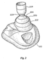
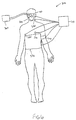
- Fig. 2 illustrates one embodiment of a facial mask 100 to which is coupled a valve system 200.
- Mask 100 is configured to be secured to a patient's face so as to cover the mouth and nose.
- Mask 100 and valve system 200 are examples of one type of equipment that may be used to lower intrathoracic pressures and thereby lower intracranial and intraocular pressures.
- other valve systems and other coupling arrangements may be used including, for example, those previously referenced. As such the invention is not intended to be limited to the specific valve system and mask described below.
- Valve system 200 includes a valve housing 202 with a socket 204 into which a ball 206 of a ventilation tube 208 is received.
- ventilation tube 208 may rotate about a horizontal axis and pivot relative to a vertical axis.
- a respiratory source such as a ventilation bag, may be coupled to tube 208 to assist in ventilation.
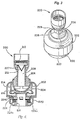
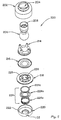
- Disposed in ventilation tube 208 is a filter 210 that is spaced above a duck bill valve 212.
- a diaphragm holder 214 that holds a diaphragm 216 is held within housing 202.
- Valve system 200 further includes a patient port 218 that is held in place by a second housing 220.
- Housing 220 conveniently includes tabs 222 to facilitate coupling of valve system 200 with facial mask 100. Also held within housing 220 is a check valve 224 that comprises a spring 224a, a ring member 224b, and an o-ring 224c. Spring 224a biases ring member 224b against patient port 218. Patient port 218 includes bypass openings 226 that are covered by o-ring 224c of check valve 224 until the pressure in patient port 218 reaches a threshold negative pressure to cause spring 224a to compress.
- expired gases flow through port 218 and lift up diaphragm 214.
- the gases then flow through a passage 227 in ventilation tube 208 where they exit the system through openings 229 (see Fig. 3 ).
- valve system 200 prevents respiratory gases from flowing into the lungs until a threshold negative intrathoracic pressure level is exceeded.
- a threshold negative intrathoracic pressure level When this pressure level is exceeded, check valve 224 is pulled downward as springs 224a are compressed to permit respiratory gases to flow through openings 226 and to the patient's lungs by initially passing through tube 208 and duck bill valve 212.
- Valve 224 may be set to open when the negative intrathoracic pressure is in the range from about 0 cm H2O to about -25 cm H2O, and more preferably from about -2 cm H2O to about -20 cm H2O. Hence, the magnitude and duration of negative intrathoracic pressure may be enhanced during patient inhalation by use of valve system 200.
- recoil spring 224a again close check valve 224. In this way, pressure within the venous blood vessels that transport blood out of the brain are also lowered. In so doing, more blood is drawn out of the brain to reduce intracranial and intraocular pressures.
- System 300 may conveniently include facial mask 100 and valve system 200, although any of the valve systems or interfacing mechanisms described herein or the like may be used.
- Valve system 200 may conveniently be coupled to a controller 310.
- controller 310 may be used to control the impedance level of valve system 200 in a manner similar to any of the embodiments described or incorporated herein.
- the level of impedance may be varied based on measurements of physiological parameters, or using a programmed schedule of changes.
- System 300 may include a wide variety of sensors and/or measuring devices to measure any of the physiological parameters described herein. These sensors or measuring devices may be integrated within or coupled to valve system 200 or facial mask, or may be separate.
- valve system 200 may include a pressure transducer for taking pressure measurements (such as intrathoracic pressures, intracranial pressures, intraocular pressures), a flow rate measuring device for measuring the flow rate of air into or out of the lungs, or a CO2 sensor for measuring expired CO2.
- pressure measurements such as intrathoracic pressures, intracranial pressures, intraocular pressures
- flow rate measuring device for measuring the flow rate of air into or out of the lungs
- CO2 sensor for measuring expired CO2.
- sensors or measuring devices examples include a heart rate sensor 330, a blood pressure sensor 340, and a temperature sensor 350. These sensors may also be coupled to controller 310 so that measurements may be recorded. Further, it will be appreciated that other types of measuring devices may be used to measure various physiological parameters, such as oxygen saturation and/or blood levels of 02, blood lactate, blood pH, tissue lactate, tissue pH, blood pressure, pressures within the heart, intrathoracic pressures, positive end expiratory pressure, respiratory rate, intracranial pressures, intraocular pressures, respiratory flow, oxygen delivery, temperature, end tidal CO2, tissue CO2, cardiac output or the like.
- physiological parameters such as oxygen saturation and/or blood levels of 02, blood lactate, blood pH, tissue lactate, tissue pH, blood pressure, pressures within the heart, intrathoracic pressures, positive end expiratory pressure, respiratory rate, intracranial pressures, intraocular pressures, respiratory flow, oxygen delivery, temperature, end tidal CO2, tissue CO2, cardiac output or the like.
- controller 310 may be used to control valve system 200, to control any sensors or measuring devices, to record measurements, and to perform any comparisons.
- a set of computers and/or controllers may be used in combination to perform such tasks.
- This equipment may have appropriate processors, display screens, input and output devices, entry devices, memory or databases, software, and the like needed to operate system 300.
- a variety of devices may also be coupled to controller 310 to cause the person to artificially inspire.
- such devices may comprise a ventilator 360, an iron lung cuirass device 370 or a phrenic nerve stimulator 380.
- Ventilator 360 may be configured to create a negative intrathoracic pressure within the person, or may be a high frequency ventilator capable of generating oscillations at about 200 to about 2000 per minute.
- ICP intracranial pressures
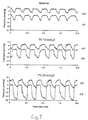
- intrathoracic pressures were recorded, with 0 cmH2O inspiratory impedance and then with inspiratory impedances of 5,10,15, and 20 cm H2O.
- ICP impedance threshold valve
- the intracranial pressure was approximately 8/4 mmHg. With increasing amounts of inspiratory impedance, the intracranial pressure was lowered proportionally as shown in Figure 7 . The intracranial pressure was 6/-2 mmHg when the pig breathed through an impedance of 20 cm H2O. These findings were observed in multiple pig studies and were reproducible.
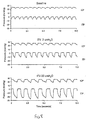
- the Millar catheter was inserted 3 cm into the pig's brain. The intracranial pressure increased secondary to the trauma associated with the insertion of the probe. The intracranial pressure increased to 25/22 mmHg at the new baseline.
- the impedance threshold valve was evaluated at different levels of resistance ( Fig. 8 ). Again, there was a decrease in intracranial pressure proportional to the degree of inspiratory impedance.
- intracranial pressures were increased in the setting of recovery from cardiac arrest.
- the example used a pig model with ventricular fibrillation for 6 minutes followed by cardiopulmonary resuscitation for 6 minutes, followed by defibrillation.
- Spontaneous breathing resulted in an up to 50% decrease in intracranial pressures when the animals breathed through an inspiratory impedance of 10 cm H2O using a valve system similar to Example 1.
- the intrathoracic pressure decreased relative to the rest of the body, creating a suction effect that reduced the pressure in the venous blood vessels draining the brain, thereby reducing intracranial pressures.
- the invention further provides techniques and devices for reducing intracranial pressure (ICP) by facilitating movement of cerebral spinal fluid (CFS).
- ICP intracranial pressure
- CFS cerebral spinal fluid
- the solid matter of the brain contents makes up about 80-85% of the material enclosed by the skull. Cerebral blood volume accounts for 3-6% and CSF for 5-15%. See, Anesthesia, Third Edition Editor, Ron Miller. Chapter authors: Shapiro and Drummond. Chapter 54 (1990 ), the complete disclosure of which is herein incorporated by reference.
- CSF moves within the brain from its site of production to its site of reabsorption in the brain in an unimpeded manner under normal physiological states. Since the contents in the brain are practically incompressible, a change in volume of any one of the three major components (brain matter, blood volume, CSF volume) results in a reciprocal change in one or both of the other brain components.
- the volume of the brain expands, secondary to an increase in the non-CSF component(s), some of the CSF is forced to other locations, including through the foramen magnum (hole in skull connecting skull to space where the spinal cord is located) and into the CSF fluid space surrounding the spinal cord.
- the non-CSF components expand in volume or size, the intracranial pressure rises.
- ICP levels are 10-15 mmHg when supine. At levels greater than 15-20 mmHg, damage to the brain can occur secondary to compression and resultant tissue ischemia (lack of adequate blood flow).
- a reduction in ICP levels can be achieved by a number of clinical interventions including water restriction, diuretics, steroids, hyperventilation, a reduction of cerebral venous pressure, hypothermia, CSF drainage, and surgical decompression.
- Increased ICP results in reduced CSF fluid movement and translocation.
- CSF fluid production generally remains constant (about 150 ml/day) despite elevated ICP.
- CSF fluid reabsorption is can be slowed by elevated ICP.
- central venous pressures may be reduced. In turn, this results in a decrease in ICP and results in an increase in CSF fluid movement or translocation and reabsorption. This results in a further reduction in ICP.
- the valve systems of the invention may be used in spontaneously breathing individuals, in patients ventilated with negative pressure ventilation or in patients ventilated with a ventilator that causes a decrease in central venous pressures for at least a portion of the respiratory cycle.
- a ventilator that causes a decrease in central venous pressures for at least a portion of the respiratory cycle.
- Each time the intrathoracic pressure is reduced with the valve systems of the invention there is a concomitant reduction in ICP and an increase in the movement of CSF.
- ICP concomitant reduction in ICP and an increase in the movement of CSF.
- the sinusoidal movement occurs in spontaneously breathing people because of the change in pressure in the thorax that is transmitted to the brain via the venous blood vessels.
- the normally fluctuating CSF pressures (the pressure increases and decreases with each inspiration) are altered by the valve systems.
- valve systems create a lower trough value thereby creating an overall created change in the ICP with each inspiration.
- a similar effect can be produced with the valve systems when used with a variety of ventilator devices, including an iron lung, a phrenic nerve stimulator (such as those described in U.S. Patent Nos. 6234985 ; 6224562 ; and 6312399 , incorporated herein by reference), a suction cup on the chest that is used to periodically expand the chest and the like.
- FIG. 9A the brain 400 is shown under normal conditions.
- the brain 400 is surrounded by CSF 402 which is produced at a site 404.
- the CFS in turn is surrounded by the skull 406.
- Blood enters brain 400 through an artery 408 and exits through a vein 410.
- Vein 410 also includes a site 412 of CFS drainage.
- Shown in Fig. 9A is an arrow showing the direction of CFS flow when draining.
- Extending from brain 400 is the spinal cord 414 that is surrounded by the foramen magnum 416.
- Fig. 9B the brain 400 is significantly swollen which reduces the space 402 where the CFS is located.
- the swelling of the brain 400 can cause blockage of CSF to the spinal cord 414 as shown by arrow 418.
- movement of CSF to site 412 is reduced to hinder movement of CSF out of the skull 406.
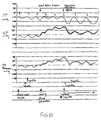
- Fig. 10 the effects of contracting the atria of the heart on ICP will be described.
- contraction of the atria results in a phasic movement in ICP. This can be most clearly demonstrated during cardiac ventricular fibrillation.
- the atria often beat spontaneously and the pressure of each contraction and relaxation waveform is transmitted immediately to the brain and is reflected in nearly identical fluctuations in ICP.
- the inventor has discovered that the fluid systems (venous blood vessels and CSF) are so closely linked, that subtle changes in the heart rhythm result in immediate changes in CSF pressure.
- the rise in right heart pressures as a result of these conditions results in an increase in ICP.
- the intracranial pressure rises and the sinusoidal pattern of ICP amplitude changes becomes dampened.
- ICP intrathoracic pressure
- RA right atrial
- ICP intracranial pressure
- the valve systems can used in patients with heart rhythms, such as atrial fibrillation, or patients with heart failure who have increased ICP in order to reduce their ICP, increase CSF fluid movement and translocation, and ultimately help them to improve their brain function.
- the amount of inspiratory resistance, or the amount of negative intrathoracic pressure generation can be controlled or regulated by feedback from measurement of ICP, blood pressure, respiratory rate, or other physiological parameters.
- a system could include a closed loop feedback system.
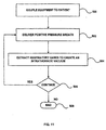
- Fig. 11 is a flow chart illustrating another method for treating a person suffering from head trauma associated with elevated intracranial pressures.
- head trauma associated with elevated intracranial pressures.
- such techniques may also be used to treat those suffering from low blood pressure or those in cardiac arrest, among others.
- the techniques are particularly useful in cases where the person is not breathing, although in some cases they could be used for breathing patients as well.
- a person's intrathoracic pressure is lowered to decrease intracranial pressures. In turn, this assists in reducing secondary brain injury.
- equipment may be coupled to the person to assist in lowering the person's intrathoracic pressure.
- a wide variety of equipment and techniques may be used to decrease the intrathoracic pressure, including using a mechanical ventilator capable of extracting respiratory gases, such as the one described in U.S. Patent No. 6,584,973 , a phrenic nerve or other muscle stimulator (with or without the use of an impedance mechanism, such as those described in U.S. Patent Nos.
- a positive pressure breath is delivered to the person as illustrated in step 502. This may be done with a mechanical ventilator, a ventilatory bag, mouth to mouth, and the like. This is followed by an immediate decrease in intrathoracic pressure. This may be done by extracting or expelling respiratory gases from the patient's lungs as shown in step 504. Any of the techniques described above may be used to lower the intrathoracic pressure. Such a reduction in intrathoracic pressure also lowers central venous pressure and intracranial pressure.
- the vacuum effect during the expiratory phase may be constant, varied over time or pulsed. Examples of different ways to apply the vacuum are described later with respect to Figs. 12A-12C .
- the initial positive pressure breath may be supplied for a time of about 250 milliseconds to about 2 seconds, and more preferably from about 0.75 seconds to about 1.5 seconds.
- the respiratory gases may be extracted for a time that is about 0.5 to about 0.1 to that of the positive pressure breath.
- the positive pressure breath may be delivered at a flow rate in the range from about 0.1 liters per second to about 5 liters per second, and more preferably from about 0.2 liters per second to about 2 liters per second.
- the expiratory flow (such as when using a mechanical ventilator) may be in the range from about 0.1 liters per second to about 5 liters per second, and more preferably from about 0.2 liters per second to about 2 liters per second.
- the vacuum may be maintained with a negative flow or without any flow.
- the vacuum may be in the range from about 0 mmHg to about -50 mmHg, and more preferably from about 0 mmHg to about -20 mmHg.
- step 506 the process of delivering a positive pressure breath and then immediately lowering intrathoracic pressures may be repeated as long as necessary to control intracranial pressures. Once finished, the process ends at step 508.
- positive pressure breaths and the vacuum may vary depending upon a particular application. These may be applied in a variety of waveforms having different durations and slopes. Examples include using a square wave, biphasic (where a vacuum is created followed by positive pressure, decay (where a vacuum is created and then permitted to decay), and the like. Three specific examples of how this may occur are illustrated in Figs. 12A-12C , although others are possible.
- the time during which the positive pressure breath occurs may be defined in terms of the inspiratory phase
- the time during which the intrathoracic pressure is lowered may be defined in terms of the expiratory phase.
- the positive pressure breaths may occur at about 10 to about 16 breaths per minute, with the inspiratory phase lasing about 1.0 to about 1.5 seconds, and the expiration phase lasing about 3 to about 5 seconds.
- respiratory gases are quickly supplied up to a pressure of about 22 mmHg. This is immediately reversed to a negative pressure of about -10 mmHg. This pressure is kept relatively constant until the end of the expiratory phase where the cycle is repeated.
- Fig. 12B the positive pressure is more slowly applied.
- the pressure is rapidly reversed to a negative pressure of about -20 mmHg.
- the negative pressure gradually declines to about 0 mmHg at the end of the expiratory phase.
- the cycle is then repeated.
- the positive pressure is reduced compared to the cycle in Fig. 12A , and the negative pressure is initially lower, but allowed to gradually increase.
- the technique is designed to help reduce a possible airway collapse.
- Fig. 12C the positive pressure is brought up to about 20 mmHg and then immediately brought down to about 0 mmHg.
- the negative pressure is then gradually increased to about -20 mmHg toward the end of the expiratory phase. This cycle is designed to help reduce a possible airway collapse.
- Figs. 13A and 13B schematically illustrate one embodiment of a device 500 that may be used to lower intrathoracic pressures in a non-breathing patient.
- Device 500 comprises a housing 502 having an interface opening 504 that may be directly or indirectly coupled to the patient's airway using any type of patient interface.
- Housing 502 also includes a vacuum source interface 506 that may be in fluid communication with any type of device or system capable of producing a vacuum.
- a means to regulate the vacuum such as a pressure responsive valve system 508.
- Device 500 further includes a ventilation interface 510 that may be used to provide a breath to the patient, if needed, when the vacuum is not applied.
- the vacuum may be provided by essentially any type of a vacuum source, and the regulator may comprise an impedance valve, such as those described in U.S. Patent Nos. 5,551,420 ; 5,692,498 ; 6,062,219 ; 5,730,122 ; 6,155,257 ; 6,234,916 ; 6,224,562 ; 6,234,985 ; 6,224,562 ; 6,312,399 ; and 6,463,327 as well as others described herein.
- a variety of ventilation sources may be used, such as, for example, a bag valve resuscitator, that is coupled to interface 510.
- Device 500 may further include a mechanism 512 to inhibit the vacuum when delivering a breath to the patient from the bag valve resuscitator. Once the breath is delivered, mechanism 512 operates to permit the vacuum within the thorax to be reapplied.
- the mechanism 512 used to turn off and on the vacuum source can include a slider switch that moves to close off the branch in housing 500 having the vacuum source as illustrated in Fig. 13B . However, other types of switches or mechanisms may be used.
- the vacuum source may have a controller that is configured to shut off the vacuum when the breath is administered so that mechanism 512 is not needed. Also, a controller and appropriate sensors could be used to sense when the breath is delivered and stopped so that mechanism 512 may be appropriately operated by the controller.
- mechanism 512 moves back to the position illustrated in Fig. 13A so that the vacuum may be supplied to the patient. When the vacuum reaches a threshold amount, regulator 508 operates to maintain the level of vacuum at about the threshold amount.
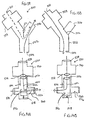
- Figs. 14A and 14B illustrate another embodiment of a device 530 that may be used to treat a patient.
- Device 530 operates using similar principles as device 500 illustrated in Figs. 13A and 13B .
- Device 530 comprises a housing 532 having a patient interface 534 that may be coupled to the patient's airway and a vacuum interface 536 that may be coupled to a vacuum source. Housing 532 also includes a ventilation interface 538 through which a positive pressure breath may be supplied.
- a vacuum regulator 540 is also coupled to housing 532 that regulates the amount of vacuum supplied to the patient.
- a flow regulator that may be used is described below with references to Figs. 15A and 15B . However, it will be appreciated that any of the flow regulators described herein may be used.
- Flow control device 542 Disposed within housing 532 is a flow control device 542 that is used orchestrate gas flows through housing 532.
- Flow control device 542 comprises a cylindrical member 544 that may slide within housing 532 and includes a flow path 546 that permits gas flow between interfaces 534 and 536 when flow control device 542 is in the position illustrated in Fig. 14A .
- a spring 548 or other biasing mechanism is used to hold flow control device 542 in the home position illustrated in Fig. 14A .
- Flow control device 542 also includes a flow path 550 illustrated by the arrow in Fig. 14A to permit gas flows between regulator 540 and interface 536.
- a vacuum may be supplied through interface 536 which lowers the person's intrathoracic pressure. If the vacuum becomes to great, gas flows are permitted through regulator 540 to lower the amount of vacuum.
- flow control device 542 also includes a flow path 552 that passes from interface 538 to interface 534. This permits a positive pressure breath to be supplied to the patient through interface 538. More specifically, as gasses are injected through interface 538, they flow into flow control device 542 causing it to move within housing 532 and compress spring 548. In so doing, flow path 546 closes as it becomes blocked by housing 532. Flow path 550 also closes, leaving only flow path 552 opened to permit the respiratory gases to flow to the patient. When the positive pressure breath stops, spring 548 forces flow control device back to the home position where the vacuum is once again supplied to the patient.
- Flow control device 542 may include a cup-shaped opening 556 which helps to move the device 542 along with minimal force applied.
- Device 530 may also include an optional pressure pop-off regulator 560.
- the pop-off regulator 560 opens allowing for pressure relief above the desired vacuum pressure.
- the pop-off regulator 560 may be configured to open for pressures greater than about 20 to about 100 mmHg.
- Figs. 13 and 14 are shown with mechanical switching mechanisms, others may also be used, such as magnetic, electronic, or electrical.
- Other kinds of possible switches include a ball valve, flapper valve, fish mouth valve, or other mechanical means as well as electric or electronic valving systems, including a solenoid, to allow for temporary inhibition of the vacuum once the positive pressure breath is delivered from the ventilation source.
- Additional regulators can also be used on the vacuum source to limit the flow or force of the vacuum.
- the vacuum source could be configured to provide a constant vacuum once a threshold level has been achieved.
- the vacuum regulator and impedance valves 508 and 530 may be variable or set at a fixed level of impedance.
- the vacuum source may also be a suction line or come from a venture device attached to an oxygen tank that could both provide oxygen to the patient and a vacuum source. Further, the invention is not limited to using an impedance valve, as shown, to regulate the vacuum. Multiple switching and regulating means may be used instead.
- the ventilation source is similarly not limiting and may include sources such as mouth-to-mouth, a bag-valve resuscitator, an automatic ventilator, and the like.
- Figs. 15A and 15B illustrate flow regulator 540 in greater detail.
- Regulator 540 comprises a housing 570 having a patient port 572 and a ventilation port 574.
- a supplemental oxygen port 576 may also be provided.
- Gas may flow through housing 570 (between ports 572 and 574) through one of two flow paths.
- the first flow path is blocked by a one way check valve 578 that comprises a check valve gasket 580 and a spring 582.
- the second flow path is blocked by a diaphragm 584.
- a vacuum is experienced at patient port 572 as the vacuum source draws a vacuum at port 536 (See Fig. 14A ).
- spring 582 compresses to move gasket 580 downward, thereby creating a flow path as illustrated in Fig. 15B .
- diaphragm 584 closes to prevent air from flowing through the other flow path.
- Gasket 580 remains spaced apart from the opening as long as the vacuum is at the threshold level. In this way, regulator 540 is able to maintain the vacuum at a constant level.
- the vacuum When ready to ventilate the patient, the vacuum is stopped and respiratory gases are injected into port 574 and/or port 576. These gasses lift diaphragm 584 to permit the gases to flow to the patient.
- Example 3 is another non-limiting example illustrating how intracranial pressures and intrathoracic pressures may be lowered and systolic arterial pressure may be increased according to one aspect of the invention.
- 30 kg pigs were anesthetized with propofol.
- IVTP Intrathoracic pressures
- SBP Systolic aortic blood pressures
- An objective of this example was to evaluate the acute use of a novel inspiratory impedance threshold device (ITD) attached to a controlled but continuous vacuum (CV) source to decrease intrathoracic pressure (ITP) and intracranial pressure (ICP) but simultaneously increase mean arterial pressure (MAP), coronary perfusion pressure (CPP) and cerebral perfusion pressure (CerPP) in an apneic pig model of sequential insults of cardiac arrest and fixed-bleed hemorrhage hypotensive shock. This animal model is associated with both elevated ICP after cardiac arrest and significant hypotension after hemorrhage.
- ITD inspiratory impedance threshold device
- CV controlled but continuous vacuum
- MAP mean arterial pressure
- CPP cerebral perfusion pressure
- This animal model is associated with both elevated ICP after cardiac arrest and significant hypotension after hemorrhage.
- This example used 6 female farm pigs (28-32kg) that were anesthetized with propofol, intubated and ventilated to maintain normocarbia and 02 saturation >90%. Ventricular fibrillation was induced and followed by 6 min of no treatment, 6 min of standard CPR, and then defibrillation. After return of spontaneous circulation and while ventilated mechanically at 10 breaths/min, 35% of blood volume was removed with a rate of 60 cc/min. Five min later ITD-CV was applied for 5 min along with positive pressure ventilation with 100% oxygen at a rate of 10 bpm. The ITD-CV was then removed and positive pressure ventilation at a rate of 10 breaths/min was reapplied. Hemodynamic parameters and arterial blood gases were assessed before, during, and after ITD-CV application. Statistical analysis was performed with a paired t-test and ANOVA to compare +/- ITD-CV use.
- a medical method for treating a person comprising: delivering a positive pressure breath to the person; extracting respiratory gases from the person's airway using a vacuum following the positive pressure breath to create an intrathoracic vacuum to lower pressures in the heart and to enhance blood flows back to the heart; and repeating the steps of delivering positive pressure breaths and extracting respiratory gases.
- the person is suffering from ailments selected from a group consisting of head trauma associated with elevated intracranial pressures, low blood pressure, low blood circulation, low blood volume, cardiac arrest and heart failure.
- the method may further comprise regulating the amount of intrathoracic vacuum using a threshold valve that is in fluid communication with the person's airway.
- the threshold valve may be configured to open when the person's negative intrathoracic pressure reaches about-3 cm H20 to about- 20cm H20 to permit respiratory gases to flow into the person's airway.
- the method may further comprise stopping application of the vacuum when applying the positive pressure breath using a switching arrangement.
- the positive pressure breath may be delivered using source selected from a group consisting of a mechanical ventilator, a hand held bag valve resuscitator, mouth-to-mouth, or a means to provide intermittent positive pressure ventilation.
- the respiratory gases may be extracted with a constant extraction, varied over time, or a pulsed extraction.
- the breath may be delivered for a time in the range for about 250 milliseconds to about 2 seconds.
- the breath may be delivered at a rate in the range from about 0.1 liters per seconds to about 5 liters per second.
- the vacuum may be maintained at a pressure in the level from about 0 mmHg to about-50 mmHg.
- the vacuum may be maintained with negative flow or without flow.
- the time the positive pressure breath is supplied relative to the time in which respiratory gases are extracted may be in the range from about 0.5 to about 0.1.
- the respiratory gases may be extracted using equipment selected from a group consisting of a mechanical ventilator, a vacuum with vacuum regulator, a phrenic nerve stimulator, an extrathoracic vest, a ventilator bag, and an iron lung cuirass device.
- the respiratory gases may be lowered to an intrathoracic pressure of about-5 mmHg to about-10 mmHg and then kept generally constant until the next positive pressure breath.
- the positive breath may be slowly delivered and the respiratory gases may be rapidly lowered to an intrathoracic pressure of about-5 mmHg to about-20 mmHg and then gradually reduced towards about 0 mmHg.
- the respiratory gases may be slowly lowered to a pressure of about-5 mmHg to about-20 mm Hg.
- a device for lowering intrathoracic pressures comprising: a means to interface with the patient's airway; a means to repeatedly extract respiratory gases from the patient's lungs and airway to create and periodically maintain a negative intrathoracic pressure; a means to repeatedly regulate the extraction of respiratory gases within the patient's lungs and airway; and a means to deliver a positive pressure breath, to periodically provide inspiration of respiratory gases.
- the means to extract respiratory gases may comprise vacuum source selected from a group consisting of a suction line or venturi device attached to an oxygen tank.
- the device may further comprise a switching mechanism to stop the extraction of respiratory gases during delivery of a positive pressure breath, wherein the switching mechanism is selected from a group consisting of mechanical devices, magnetic devices, and electronic devices.
- the means for extracting respiratory gases may be selected from a group consisting of a mechanical ventilator, a vacuum with vacuum regulator, a phrenic nerve stimulator, an extrathoracic vest, a ventilator bag, and an iron lung cuirass device
- the means for regulating may comprise a threshold valve that is in fluid communication with the person's airway.
- the threshold valve may be configured to open when the person's negative intrathoracic pressure reaches about-3 cm H20 to about- 20cm H20 to permit respiratory gases to flow into the person's airway.
- the means for delivering a positive pressure breath may be selected from a group consisting of a mechanical ventilator, a hand held bag valve resuscitator, mouth-to-mouth, or a means to provide intermittent positive pressure ventilation.
- a device for lowering intrathoracic pressures comprising: a housing having an interface that is adapted to couple the housing to the person's airway; a vacuum source in fluid communication with the housing for repeatedly extracting respiratory gases from the person's lungs and airway to create and periodically maintain a negative intrathoracic pressure; a vacuum regulator to regulate the extraction of respiratory gases from the patient's lungs and airway; and a positive pressure source in fluid communication with the housing for intermittently supplying positive pressure breaths to the person.
- a device for decreasing intracranial or intraocular pressures comprising: a housing having an inlet opening and an outlet opening that is adapted to be interfaced with a person's airway; a valve system that is operable to regulate respiratory gas flows through the housing and into the person's lungs during spontaneous or artificial inspiration, the valve system assisting in lowering intrathoracic pressures during each inspiration to repetitively lower pressures in the venous blood vessels that transport blood out of the head to thereby reduce intracranial or intraocular pressures.
- the valve system may normally be closed and be configured to open to permit respiratory gasses to freely flow to the person's lungs when the negative intrathoracic pressure reaches a pressure in the range from about 0 cmH20 to about-25 cmH20 in order to reduce intracranial or intraocular pressures.
- the device may further comprise means for causing the person to artificially inspire through the valve system.
- the means for causing the person to artificially inspire may be selected from a group consisting of an electrode, an iron lung cuirass device, a chest lifting device and a ventilator.
- the device may further comprise a mechanism for varying the level of impedance of the valve system.
- the device may further comprise at least one physiological sensor that is configured to monitor at least one physiological parameter of the person, and wherein the mechanism for varying the level of impedance is configured to receive signals from the sensor and to vary the level of impedance of the valve system based on the signals.
- the sensor may be selected from a group of sensors that are configured to measure parameters selected from a group consisting of: respiratory rate, intrathoracic pressure, intratracheal pressure, blood pressure, heart rate, end tidal C02, oxygen level, and intracranial pressure.
- the device may further comprise a coupling mechanism that is configured to couple the valve system to the person's airway.
- the coupling mechanism may be selected from a group consisting of a mouthpiece, an endotracheal tube, and a face mask.
- the valve system may comprise an inflow valve that is selected from a group of valves consisting of a fish mouth valve, a spring-poppet valve, a ball valve, a flexible plug valve, a slotted airway resistance valve, a spring biased valve, a movable disk valve, a compressible airway valve, an iris valve, an automated valve, and a sequential series of adjusting valves.
- a method for decreasing intracranial pressures comprising: actively decreasing the person's negative intrathoracic pressure to lower pressures in the venous blood vessels that transport blood out of the head to thereby reduce intracranial pressures.
Abstract
A device 500 for lowering intrathoracic pressure in a patient, the device characterized by:
a housing 502 comprising an interface 504 adapted to couple the housing to a patient's airway; a negative pressure source 506 in fluid communication with the housing and configured to extract respiratory gases from the patient's lungs and airway; means 508 to regulate the negative pressure source to create and periodically maintain a negative intrathoracic pressure until a positive pressure breath is applied; and a positive pressure port 510 in fluid communication with a positive pressure source for intermittently supplying positive pressure breaths to the person.
a housing 502 comprising an interface 504 adapted to couple the housing to a patient's airway; a negative pressure source 506 in fluid communication with the housing and configured to extract respiratory gases from the patient's lungs and airway; means 508 to regulate the negative pressure source to create and periodically maintain a negative intrathoracic pressure until a positive pressure breath is applied; and a positive pressure port 510 in fluid communication with a positive pressure source for intermittently supplying positive pressure breaths to the person.
Description
- This application is a continuation in part application of
U.S. Patent Application No. 10/660,462, filed September 11, 2003 - Patent Application No.
10/460,558, filed June 11, 2003 U.S. Patent Application No. 10/426,161, filed April 28, 2003 - This application is also related to
U.S. Patent Application No. 10/765,318, filed January 26, 2004 - This invention relates generally to the field of intracranial and intraocular pressures. More specifically, the invention relates to devices and methods for decreasing intracranial, intraocular and systemic arterial pressures and increasing systemic vital organ perfusion, such as those resulting from a traumatic head injury and other injuries.
- Head trauma and shock are generally regarded as the leading cause of morbidity and mortality in the United States for children and young adults. Head trauma often results in swelling of the brain. Because the skull cannot expand, the increased pressures within the brain can lead to death or serious brain injury. While a number of therapies have been evaluated in order to reduce brain selling, including use of hyperventilation and steroids, an effective way to treat intracranial pressures remains an important medical challenge. Similarly, multi-organ injury associated with head trauma and other vital organ damage is associated with increased pressures within the brain and decreased vital organ perfusion. These patients have an extremely high mortality rate and similarly remain a major medical challenge.
- In one embodiment, the invention provides a device for decreasing intracranial or intraocular pressures and increasing systemic blood pressures and organ perfusion. The device comprises a housing having an inlet opening and an outlet opening that is adapted to be interfaced with a person's airway. The device further includes a valve system that is operable to regulate respiratory gas flows through the housing and into the person's lungs during spontaneous or artificial inspiration. For a person who requires artificial inspiration, the valve system can be attached to a vacuum source. The valve system assists in lowering intrathoracic pressures during spontaneous inspiration and in non-breathing patients when not actively delivering a breath to continuously or intermittently lower pressures in the venous blood vessels that transport blood out of the head to thereby reduce intracranial or intraocular pressures and increase systemic blood pressures In addition, the invention lowers the pressures within the left and right heart, when positive pressure ventilations are not being provided, thereby helping to increase the efficiency of heart function. The invention can therefore be used to treat patients suffering from a number of disease states including but not limited to those suffering from elevated intracranial pressures, intra-ocular pressures, circulatory collapse, and cardiac arrest, and heart failure.
- Such a device may also be used to facilitate movement of cerebral spinal fluid. In so doing, intracranial pressures may be further reduced. Such a device may therefore be used to treat those suffering from head trauma associated with elevated intracranial pressures as well as those suffering from heart conditions that increase intracranial pressures.
- In one aspect, the valve system is configured to open to permit respiratory gasses to freely flow to the person's lungs when the negative intrathoracic pressure reaches a pressure in the range from about -2 cmH2O to about -20 cmH2O in order to reduce intracranial or intraocular pressures. In this way, the negative intrathoracic pressure is lowered until a threshold pressure is reached, at which time the valve opens. The cycle may be repeated continuously or periodically to repetitively lower intrathoracic pressures. The device may include means for compressing the chest to improve blood circulation in patents in or with low blood circulation or cardiac arrest. The compression could be accomplished with an automated chest compression, a circumferential vest, and the like. This would improve blood flow to the heart and brain in patients with low blood circulation.
- The device may also include means for causing the person to artificially inspire through the valve system. For example, the device may utilize an electrode, an iron lung cuirass device, a chest lifting device, a ventilator or the like.
- In another embodiment, the device may comprise a means to reduce intrathoracic pressure by applying a vacuum within the airway. The vacuum may be adjusted in terms of frequency, amplitude, and duration. This results in a decrease in intracranial pressure in proportion to the degree of vacuum applied. Hence, intracranial pressures may be reduced simply by manipulating airway pressures to reduce intrathoracic pressures. In addition, the vacuum created within the thorax enhances venous blood flow back to the heart, thereby simultaneously increasing cardiac output and systemic vital organ perfusion.
- The device may further include a mechanism for varying the level of impedance of the valve system. This may be used in combination with at least one physiological sensor that is configured to monitor at least one physiological parameter of the person. In this way, the mechanism for varying the level of impedance may be configured to receive signals from the sensor and to vary the level of impedance of the valve system based on the signals. Examples of sensors that may be used include those that measure respiratory rate, intrathoracic pressure, intratracheal pressure, blood pressure, heart rate, end tidal CO2, oxygen level, intracranial perfusion, and intracranial pressure.
- In one aspect, a coupling mechanism may be used to couple the valve system to the person's airway. Examples of coupling mechanisms include a mouthpiece, an endotracheal tube, and a face mask.
- A wide variety of valve systems may be used to repetitively decrease the person's intrathoracic pressure. For example, valve systems that may be used include those having spring-biased devices, those having automated, electronic or mechanical systems to occlude and open a valve lumen, duck bill valves, ball valves, other pressure sensitive valve systems capable of opening a closing when subjected to low pressure differentials triggered either by spontaneous breathing and/or external systems to manipulate intrathoracic pressures (such as ventilators, phrenic nerve stimulators, iron lungs, and the like).
- In another embodiment, the invention provides a method for decreasing intracranial or intraocular pressures. According to the method, a valve system is coupled to a person's airway and is configured to at least periodically reduce or prevent respiratory gases from flowing to the person's lungs. With the valve system coupled to the airway, the person's negative intrathoracic pressure is repetitively decreased to in turn repetitively lower pressures in the venous blood vessels that transport blood out of the head. In so doing, intracranial and intraocular pressures are reduced. Such a method also facilitates movement of cerebral spinal fluid. In so doing, intracranial pressures are further reduced. As such, this method may also be used to treat a person suffering from head trauma that is associated with elevated intracranial pressures as well as those suffering from heart conditions that increase intracranial pressures, such as atrial fibrillation and heart failure.
- The person's negative intrathoracic pressure may be repetitively decreased as the person repeatedly inspires through the valve system. This may be done by the person's own efforts (referred to as spontaneous breathing), or by artificially causing the person to repeatedly inspire through the valve system. For example, the person may be caused to artificially inspire by repeatedly stimulating the phrenic nerve, by manipulating the chest with an iron lung cuirass device, by generating negative pressures within the thorax using a ventilator, by applying a vacuum within the thorax that can be regulated by the valve system, by applying a high frequency ventilator that supplies oscillations at a rate of about 200 to about 2000 per minute, or the like.
- In another aspect, the level of impedance of the valve system may be fixed or variable. If variable, at least one physiological parameters of the person may be measured, and the impedance level may be varied based on the measured parameters.
- To couple the valve system to the airway, a variety of techniques may be used, such as by using a mouthpiece, an endotracheal tube, a face mask or the like. Further, the respiratory gases may be prevented from entering the lungs through the valve system until a negative intrathoracic pressure in the range from about 0 cmH2O to about -25 cmH2O is achieved, at which time the valve system permits respiratory gases to flow to the lungs.
- In another embodiment, the invention provides a method for treating a person suffering from head trauma associated with elevated intracranial pressures. According to the method, a positive pressure breath is delivered to the person. Following the positive pressure breath, respiratory gases are extracted from the person's airway to create an intrathoracic vacuum. In turn, this lowers pressures in the venous blood vessels that transport blood out of the head to thereby reduce intracranial pressures. The steps of delivering positive pressure breaths and extracting respiratory gases are repeated to continue the treatment.
- In one aspect, the delivery of the positive pressure breaths and the extraction of gases are performed using a mechanical ventilator. The respiratory gases may be extracted with a constant extraction or a pulsed extraction.
- In a further aspect, the breath may be delivered for a time in the range for about 250 milliseconds to about 2 seconds. Also, the breath may be delivered at a rate in the range from about 0.1 liters per second to about 5 liters per second. In another aspect, the vacuum may be maintained at a pressure in the level from about 0 mmHg to about -50 mmHg. The vacuum may be maintained with a negative flow or without any flow. The time that the positive pressure breath is supplied relative to the time in which respiratory gases are extracted may be in the range from about 0.5 to about 0.1.
- A variety of equipment may be used to extract the respiratory gases including mechanical ventilators, phrenic nerve stimulators, ventilator bags, a vacuum attached to the airway device, iron lung cuirass devices and the like. In some cases, a threshold valve may also be coupled to the person's airway. The threshold valve may be configured to open when an adult's negative intrathoracic pressure exceeds about -3 cmH2O. For pediatric cases, the valve may open when the pressure exceeds about -2 cmH2O to about -5 cmH2O. In this way, when the person inhales, the negative intrathoracic pressure may be lowered.
- A variety of schemes may be used to deliver and extract respiratory gases. For example, respiratory gases may be extracted to achieve a pressure of about -5 mmHg to about -10 mmHg and then kept generally constant until the next positive pressure breath. As another example, the positive breath may be slowly delivered and the intrathoracic pressure may be rapidly lowered to a pressure of about -10 mmHg to about -20 mmHg and then gradually reduced towards about 0 mmHg. As a further example, the intrathoracic pressure may be slowly lowered to a pressure of about -20 mm Hg.
- In a further embodiment, the invention provides a device for lowering intrathoracic pressures. The device comprises a housing having an interface that is adapted to couple the housing to the person's airway. A vacuum source is in fluid communication with the housing for repeatedly extracting respiratory gases from the person's lungs and airway to create and periodically maintain a negative intrathoracic pressure. A vacuum regulator is used to regulate the extraction of respiratory gases from the patient's lungs and airway. Also, a positive pressure source is in fluid communication with the housing for intermittently supplying positive pressure breaths to the person. Such a device may be used to treat a variety of ailments, such as head trauma associated with elevated intracranial pressures, low blood pressure, low blood circulation, low blood volume, cardiac arrest and heart failure.
- In some cases, a switching mechanism may be used to stop the extraction of respiratory gases during delivery of a positive pressure breath. A variety of switching mechanisms may be used, such as mechanical devices, magnetic devices, and electronic devices. Also, a variety of vacuum sources may be used to extract the respiratory gases, including a mechanical ventilator, a vacuum with vacuum regulator, a phrenic nerve stimulator, an extrathoracic vest, a ventilator bag, and an iron lung cuirass device, a suction line, a venturi device attached to an oxygen tank and the like.
- To regulate the vacuum, a threshold valve may be placed in fluid communication with the person's airway. The threshold valve may be configured to open when the person's negative intrathoracic pressure reaches about -3 cm H2O to about -20cm H2O to permit respiratory gases to flow into the person's airway. Also, a variety of pressure sources may be used to deliver a positive pressure breath, such as a mechanical ventilator, a hand held bag valve resuscitator, mouth-to-mouth, or a means to provide intermittent positive pressure ventilation.
-
-
Fig. 1 is a flow chart illustrating one method for reducing intracranial and intraocular pressures according to the invention. -
Fig. 2 is a perspective view of one embodiment of a facial mask and a valve system that may be used to reduce intracranial and intraocular pressures according to the invention. -
Fig. 3 is a perspective view of the valve system ofFig. 2 . -
Fig. 4 is a cross sectional side view of the valve system ofFig. 3 . -
Fig. 5 is an exploded view of the valve system ofFig. 3 . -
Fig. 6 is a schematic diagram of a system for reducing intracranial and intraocular pressures according to the invention. -
Fig. 7 is a series of graphs illustrating the lowering of intracranial pressures in an animal study. -
Fig. 8 is a series of graphs illustrating the lowering of intracranial pressures in another animal study. -
Fig. 9A is a schematic diagram of a person's brain under normal conditions. -
Fig. 9B illustrates the brain ofFig. 9A after increased swelling. -
Fig. 10 shows three graphs illustrating the effect of lowering intrathoracic pressure on intracranial pressure and right atrial pressure. -
Fig. 11 is a flow chart illustrating another method for reducing intracranial and intraocular pressures according to the invention. -
Figs. 12A-12C show three graphs illustrating patterns for delivering a positive pressure breath and extracting respiratory gases according to the invention. -
Figs. 13A and 13B schematically illustrate one device that may be used to lower intrathoracic pressures with a non-breathing patient according to the invention. -
Figs. 14A and 14B illustrate another device that may be used to lower intrathoracic pressures with a non-breathing patient according to the invention. -
Figs. 15A and 15B illustrate one embodiment of a threshold valve system that may be used with the device ofFigs. 14A and 14B . - In a broad sense, the invention provides devices and techniques for lowering intracranial and intraocular pressures. Such devices and techniques may be particularly helpful with patients who have suffered a traumatic brain injury and those with low blood flow states and low blood pressure. One way to lower the pressure within the head but maintain or increase systemic pressures is by using a valve system that is coupled to a person's airway and that is used to lower intrathoracic pressures. In so doing, the valve systems may be used to accelerate the removal of venous blood from the brain, thereby decreasing intracranial and intraocular pressures. At the same time, the systemic pressures increase due to enhancement of venous return to the heart. Other techniques may be used as well, such as by creating a vacuum intermittently within the thorax. By reducing intracranial pressures, movement of cerebral spinal fluid is also enhanced. In so doing, intracranial pressures are further reduced thereby providing further treatment for those suffering from head trauma. In some cases, the valve systems may also be used to treat the brain function in a person suffering from a heart condition (atrial fibrillation, heart failure, cardiac tamponade, and the like) that results in elevated intracranial pressures. Such heart conditions may include, for example, atrial fibrillation or heart failure. By reducing intracranial pressures, cerebral spinal fluid movement and translocation is increased to help improve brain function.
- Intracranial pressures are regulated by the amount the cerebral perfusion pressure, which is determined by the arterial blood pressure to the head, the pressures within the skull, and the pressures within the venous system that drains blood flow from the brain. The devices and methods of the invention may be used to enhance the egress of venous blood out of the brain, thereby lowering intracranial pressures. The devices and methods can be used in patients that are breathing spontaneously and those that require assisted ventilation. To do so, the devices and methods may be used to augment the intrathoracic vacuum effect each time a patient inhales (or in the case of a non-breathing patient, each time the pressure within the chest is manipulated to fall below atmospheric pressure), thereby lowering the pressures in the thorax and in the venous blood vessels that transport blood out of the brain. The vacuum effect is transduced back into the brain, and as a result, intracranial pressures are lowered with each inspiratory effort. This in turn causes more venous blood to flow out of the head than would otherwise be possible, resulting in lower intracranial pressures and lower intraocular pressures. In addition, circulation to the vital organs is increased as the increase in venous return to the heart each time a negative intrathoracic pressure is generated results in an increase in cardiac output and improved vital organ perfusion. As such, this invention may be used to help patients suffering from low cardiac output states and low blood pressure.
- To prevent or impede respiratory gases from flowing to the lungs, a variety of impeding or preventing mechanisms may be used, including those described in
U.S. Patent Nos. 5,551,420 ;5,692,498 ;6,062,219 ;5,730,122 ;6,155,257 ;6,234,916 and6,224,562 , and inU.S. Patent Application Nos. 10/224,263, filed on August 19, 2002 10/401,493, filed March 28, 2003 09/966,945, filed September 28, 2001 09/967,029, filed September 28, 2001 - For example, the resistance to the inflow of respiratory gases may be set between about 0 cm H2O and about -25 cm H2O and may be variable or fixed. More preferably, the valve system may be configured to open when the negative intrathoracic pressure is in the range from about -2 cmH2O to about -20 cmH2O. In addition, the valve system may used continuously or on a variable basis. For example, the valve system may be used for every other spontaneous breath.
- Although not intended to be limiting, specific kinds of impedance valves that may be used to reduce intracranial and intraocular pressures include those having spring-biased devices, automated/electronic and mechanical means to occlude and open a valve lumen, duck bill valves, ball valves, and other pressure sensitive valve systems capable of opening and closing when subjected to low pressure differentials triggered either by spontaneous breathing and/or external means to manipulate intrathoracic pressure (such as ventilators, phrenic nerve stimulators, an iron lung, and the like).
- In the past, such threshold valve systems have been used to increase the venous preload on the heart and to increase cardiac output, stroke volume and blood pressure because of the augmented effects of the intrathoracic vacuum on the subsequent cardiac contraction. In contrast, the techniques of the invention function by facilitating the removal of blood from the venous side of the brain. Although there may be an increase in blood flow out of the heart to the vital organs (including to the brain) when using such valve systems, the effect of the valve systems on lowering of intracranial pressures was quite unexpected because of the known increase in blood flow to the brain. Remarkably, however, the reduction of venous blood pressures from the brain remains substantial when using the valve systems. Thus, despite the increase in blood flow to the brain, the net effect of the valve system is a decrease in intracranial pressures.
- With the valve system coupled to the person's airway, the negative intrathoracic pressure may be enhanced by inspiring through the valve system. If the person is spontaneously breathing, the person may simply breath through the valve system. If the person is not breathing, artificial inspiration may be induced using a variety of techniques, including electrical stimulation of the diaphragm, a negative pressure ventilator such as a body cuirass or iron lung, or a positive pressure ventilator capable of also generating a vacuum between positive pressure ventilations. As one example, at least some of the respiratory muscles, and particularly the inspiratory muscles, may be stimulated to contract in a repeating manner in order to cause the person to inspire through the valve system, thereby increasing the magnitude and prolonging the duration of negative intrathoracic pressure, i.e., respiratory muscle stimulation increases the duration and degree that the intrathoracic pressure is below or negative with respect to the pressure in the peripheral venous vasculature. Upon contraction of the respiratory muscles, the patient will typically "gasp". These techniques may be performed alone, or in combination with a valve system.
- Among the respiratory muscles that may be stimulated to contract are the diaphragm, the chest wall muscles, including the intercostal muscles and the abdominal muscles. Specific chest wall muscles that may be stimulated to contract include those that elevate the upper ribs, including the scaleni and sternocleidomastoid muscles, those that act to fix the shoulder girdle, including the trapezii, rhomboidei, and levatores angulorum scapulorum muscles, and those that act to elevate the ribs, including the serrati antici majores, and the pectorales majores and minores as described generally in Leslie A. Geddes, "Electroventilation - A Missed Opportunity?", Biomedical Instrumentation & Technology, July/August 1998, pp. 401-414, the complete disclosure of which is herein incorporated by reference. Of the respiratory muscles, the two hemidiaphragms and intercostal muscles appear to be the greatest contributors to inspiration and expiration. The respiratory muscles may be stimulated to contract in a variety of ways. For example, the diaphragm may be stimulated to contract by supplying electrical current or a magnetic field to various nerves or muscle bundles which when stimulated cause the diaphragm to contract. Similar techniques may be used to stimulate the chest wall muscles to contract. A variety of pulse trains, pulse widths, pulse frequencies and pulse waveforms may be used for stimulation. Further, the electrode location and timing of pulse delivery may be varied. In one particular aspect, an electrical current gradient or a magnetic field is provided to directly or indirectly stimulate the phrenic nerve.
- To electrically stimulate the inspiratory motor nerves, electrodes are preferably placed on the lateral surface of the neck over the point where the phrenic nerve, on the chest surface just lateral to the lower sternum to deliver current to the phrenic nerves just as they enter the diaphragm, on the upper chest just anterior to the axillae to stimulate the thoracic nerves, in the oral pharyngeal region of the throat, or on the larynx itself. However, it will be appreciated that other electrode sites may be employed. For example, in one embodiment the respiratory muscles are stimulated by a transcutaneous electrical impulse delivered along the lower antero-lat margin of the rib cage. In one embodiment, inspiration is induced by stimulating inspiratory muscles using one or more electrodes attached to an endotracheal tube or pharyngeal tube. To stimulate the diaphragm, the phrenic nerve may be stimulated in the neck region near C3-C7, such as between C3, C4 or C5, or where the phrenic nerves enter the diaphragm. Alternative techniques for stimulating diaphragmatic contraction include magnetic field stimulation of the diaphragm or the phrenic nerve. Magnetic field stimulation may also be employed to stimulate the chest wall muscles. Electrical field stimulation of the diaphragm or the chest wall muscles may be accomplished by placing one or more electrodes on the skin, preferably in the vicinity of the neck or the lower rib cage (although other locations may be employed) and then providing an electrical voltage gradient between electrodes that induces transcutaneous current flow to stimulate the respiratory muscles to contract. Still further, subcutaneous electrodes may also be used to stimulate respiratory muscle contraction. Other techniques are described in
U.S. Patent No. 6,463,327 , the complete disclosure of which is herein incorporated by reference. - The valve systems may have a fixed actuating pressure or may be variable so that once a desired negative intrathoracic pressure is reached, the resistance to flow may be lessened. Further, the valves of the invention may be configured to be variable, either manually or automatically. The extent to which the resistance to flow is varied may be based on physiological parameters measured by one or more sensors that are associated with the person being treated. As such, the resistance to flow may be varied so that the person's physiological parameters are brought within an acceptable range. If an automated system is used, such sensors may be coupled to a controller which is employed to control one or more mechanisms that vary the resistance or actuating pressure of the inflow valve as generally described in the references that have been incorporated by reference.
- Hence, the valve systems of the invention may also incorporate or be associated with sensors that are used to detect changes in intrathoracic pressures or other physiological parameters. In one aspect, the sensors may be configured to wirelessly transmit their measured signals to a remote receiver that is in communication with a controller. In turn the controller may use the measured signals to vary operation of the valve systems described or incorporated by reference herein. For example, sensors may be used to sense blood pressure, pressures within the heart, intrathoracic pressures, positive end expiratory pressure, respiratory rate, intracranial pressures, intraocular pressures, respiratory flow, oxygen delivery, temperature, blood pH, end tidal CO2, tissue CO2, blood oxygen, cardiac output or the like. Signals from these sensors may be wirelessly transmitted to a receiver. This information may then be used by a controller to control the actuating pressure or the resistance of an inflow valve as described in the references incorporated herein by reference.
- The techniques for reducing intracranial pressures may be used in a variety of settings. For example, the techniques may be used in person's who are spontaneously breathing, those who are not breathing but whose hearts are beating, and those in cardiac arrest. In the latter case, the techniques may use some means to create a vacuum intermittently within the thorax during the performance of CPR. This could be by using a valve system or some other type of pressure manipulation system. Further, such systems may be used in other settings as well, including when the person is breathing.
-
Fig. 1 is flow diagram illustrating one method for reducing intracranial or intraocular pressures. As shown instep 10, the process proceeds by coupling a valve system to the person's airway. Any kind of coupling mechanism may be used, such as by a mouthpiece, an endotracheal tube, a face mask, or the like. Further, any of the valve systems described or incorporated herein by reference may be used. Instep 20, the person's negative intrathoracic pressure is repetitively decreased (either artificially or by spontaneous breathing). Examples of techniques to artificially reduce the negative intrathoracic pressure include use of an iron lung cuirass device, a ventilator that is capable of generating negative pressures, a ventilator that is capable of providing high frequency oscillations at a rate of about 200 to about 2000 per minute, a phrenic nerve stimulator, or the like. As the person's negative intrathoracic pressure is repeatedly decreased while the valve system is coupled to the airway, the pressures in the venous vessels that transport blood out of the head are also lowered. In so doing, intracranial and intraocular pressures are reduced. - As shown in
step 30, various physiological parameters of the person may optionally be measured. Examples of such parameters include respiratory rate, intrathoracic pressure, intertracheal pressure, intracranial pressure, intracranial blood flow, intraocular pressure, blood pressure, heart rate, end tidal CO2, oxygen saturation, and the like. Further, as shown instep 40, the valve system's actuating threshold level may optionally be varied based on the measured physiological parameters. This may be done to maximize the amount of blood drawn out of the brain or simply to monitor the patient's condition to insure that the patient remains stable. -
Fig. 2 illustrates one embodiment of afacial mask 100 to which is coupled avalve system 200.Mask 100 is configured to be secured to a patient's face so as to cover the mouth and nose.Mask 100 andvalve system 200 are examples of one type of equipment that may be used to lower intrathoracic pressures and thereby lower intracranial and intraocular pressures. However, it will be appreciated that other valve systems and other coupling arrangements may be used including, for example, those previously referenced. As such the invention is not intended to be limited to the specific valve system and mask described below. - Referring also to
Figs. 3-5 ,valve system 200 will be described in greater detail.Valve system 200 includes avalve housing 202 with asocket 204 into which aball 206 of aventilation tube 208 is received. In this way,ventilation tube 208 may rotate about a horizontal axis and pivot relative to a vertical axis. A respiratory source, such as a ventilation bag, may be coupled totube 208 to assist in ventilation. Disposed inventilation tube 208 is afilter 210 that is spaced above aduck bill valve 212. Adiaphragm holder 214 that holds adiaphragm 216 is held withinhousing 202.Valve system 200 further includes apatient port 218 that is held in place by asecond housing 220.Housing 220 conveniently includestabs 222 to facilitate coupling ofvalve system 200 withfacial mask 100. Also held withinhousing 220 is acheck valve 224 that comprises aspring 224a, aring member 224b, and an o-ring 224c.Spring 224a biases ringmember 224b againstpatient port 218.Patient port 218 includesbypass openings 226 that are covered by o-ring 224c ofcheck valve 224 until the pressure inpatient port 218 reaches a threshold negative pressure to causespring 224a to compress. - When the patient is actively ventilated, respiratory gases are forced through
ventilation tube 208. The gases flow throughfilter 210, throughduck bill valve 212, and forces updiaphragm 214 to permit the gases to exit throughport 218. Hence, at any time the patient may be ventilated simply by forcing the respiratory gases throughtube 208. - During the exhalation phase of a breathing cycle, expired gases flow through
port 218 and lift updiaphragm 214. The gases then flow through apassage 227 inventilation tube 208 where they exit the system through openings 229 (seeFig. 3 ). - During the inhalation phase of a breathing cycle,
valve system 200 prevents respiratory gases from flowing into the lungs until a threshold negative intrathoracic pressure level is exceeded. When this pressure level is exceeded,check valve 224 is pulled downward assprings 224a are compressed to permit respiratory gases to flow throughopenings 226 and to the patient's lungs by initially passing throughtube 208 andduck bill valve 212.Valve 224 may be set to open when the negative intrathoracic pressure is in the range from about 0 cm H2O to about -25 cm H2O, and more preferably from about -2 cm H2O to about -20 cm H2O. Hence, the magnitude and duration of negative intrathoracic pressure may be enhanced during patient inhalation by use ofvalve system 200. Once the intrathoracic pressure falls below the threshold,recoil spring 224a againclose check valve 224. In this way, pressure within the venous blood vessels that transport blood out of the brain are also lowered. In so doing, more blood is drawn out of the brain to reduce intracranial and intraocular pressures. - Any of the valve systems described herein may be incorporated into a
treatment system 300 as illustrated inFig. 6 .System 300 may conveniently includefacial mask 100 andvalve system 200, although any of the valve systems or interfacing mechanisms described herein or the like may be used.Valve system 200 may conveniently be coupled to acontroller 310. In turn,controller 310 may be used to control the impedance level ofvalve system 200 in a manner similar to any of the embodiments described or incorporated herein. The level of impedance may be varied based on measurements of physiological parameters, or using a programmed schedule of changes.System 300 may include a wide variety of sensors and/or measuring devices to measure any of the physiological parameters described herein. These sensors or measuring devices may be integrated within or coupled tovalve system 200 or facial mask, or may be separate. - For example,
valve system 200 may include a pressure transducer for taking pressure measurements (such as intrathoracic pressures, intracranial pressures, intraocular pressures), a flow rate measuring device for measuring the flow rate of air into or out of the lungs, or a CO2 sensor for measuring expired CO2. - Examples of other sensors or measuring devices include a heart rate sensor 330, a blood pressure sensor 340, and a temperature sensor 350. These sensors may also be coupled to
controller 310 so that measurements may be recorded. Further, it will be appreciated that other types of measuring devices may be used to measure various physiological parameters, such as oxygen saturation and/or blood levels of 02, blood lactate, blood pH, tissue lactate, tissue pH, blood pressure, pressures within the heart, intrathoracic pressures, positive end expiratory pressure, respiratory rate, intracranial pressures, intraocular pressures, respiratory flow, oxygen delivery, temperature, end tidal CO2, tissue CO2, cardiac output or the like. - In some cases,
controller 310 may be used to controlvalve system 200, to control any sensors or measuring devices, to record measurements, and to perform any comparisons. Alternatively, a set of computers and/or controllers may be used in combination to perform such tasks. This equipment may have appropriate processors, display screens, input and output devices, entry devices, memory or databases, software, and the like needed to operatesystem 300. - A variety of devices may also be coupled to
controller 310 to cause the person to artificially inspire. For example, such devices may comprise aventilator 360, an ironlung cuirass device 370 or aphrenic nerve stimulator 380.Ventilator 360 may be configured to create a negative intrathoracic pressure within the person, or may be a high frequency ventilator capable of generating oscillations at about 200 to about 2000 per minute. - The following is a non-limiting example illustrating how intracranial pressures may be lowered according to the invention. In this example, 30 kg pigs were anesthetized with propofol. Using a micromanometer-tipped electronic Millar catheter inserted below the dura, intracranial pressures were measured continuously in the spontaneously breathing pigs. Intrathoracic pressures (ITP) were recorded using a Millar catheter placed in the trachea at the level of the carina. After stabilizing the pigs blood pressure, heart rate, and ventilation rate, intracranial pressures (ICP) and intrathoracic pressures were recorded, with 0 cmH2O inspiratory impedance and then with inspiratory impedances of 5,10,15, and 20 cm H2O. Inspiratory impedance was achieved using an impedance threshold valve (ITV) as described in
Figs. 2-5 . - At base, the intracranial pressure was approximately 8/4 mmHg. With increasing amounts of inspiratory impedance, the intracranial pressure was lowered proportionally as shown in
Figure 7 . The intracranial pressure was 6/-2 mmHg when the pig breathed through an impedance of 20 cm H2O. These findings were observed in multiple pig studies and were reproducible. Next, the Millar catheter was inserted 3 cm into the pig's brain. The intracranial pressure increased secondary to the trauma associated with the insertion of the probe. The intracranial pressure increased to 25/22 mmHg at the new baseline. Next, the impedance threshold valve was evaluated at different levels of resistance (Fig. 8 ). Again, there was a decrease in intracranial pressure proportional to the degree of inspiratory impedance. - In this example, intracranial pressures were increased in the setting of recovery from cardiac arrest. The example used a pig model with ventricular fibrillation for 6 minutes followed by cardiopulmonary resuscitation for 6 minutes, followed by defibrillation. Spontaneous breathing resulted in an up to 50% decrease in intracranial pressures when the animals breathed through an inspiratory impedance of 10 cm H2O using a valve system similar to Example 1.
- In all examples above, the intrathoracic pressure decreased relative to the rest of the body, creating a suction effect that reduced the pressure in the venous blood vessels draining the brain, thereby reducing intracranial pressures.
- The invention further provides techniques and devices for reducing intracranial pressure (ICP) by facilitating movement of cerebral spinal fluid (CFS). There are a number of causes of increased ICP including: head injury, ischemia, osmolar imbalance, cerebral edema, tumors, complications of dialysis, infections, stroke, hypertensive crises. Each can result in a slow, and in some cases, an acute rise in the ICP. The solid matter of the brain contents makes up about 80-85% of the material enclosed by the skull. Cerebral blood volume accounts for 3-6% and CSF for 5-15%. See, Anesthesia, Third Edition Editor, Ron Miller. Chapter authors: Shapiro and Drummond. Chapter 54 (1990), the complete disclosure of which is herein incorporated by reference. CSF moves within the brain from its site of production to its site of reabsorption in the brain in an unimpeded manner under normal physiological states. Since the contents in the brain are practically incompressible, a change in volume of any one of the three major components (brain matter, blood volume, CSF volume) results in a reciprocal change in one or both of the other brain components. When the volume of the brain expands, secondary to an increase in the non-CSF component(s), some of the CSF is forced to other locations, including through the foramen magnum (hole in skull connecting skull to space where the spinal cord is located) and into the CSF fluid space surrounding the spinal cord. When the non-CSF components expand in volume or size, the intracranial pressure rises. Normal ICP levels are 10-15 mmHg when supine. At levels greater than 15-20 mmHg, damage to the brain can occur secondary to compression and resultant tissue ischemia (lack of adequate blood flow). A reduction in ICP levels can be achieved by a number of clinical interventions including water restriction, diuretics, steroids, hyperventilation, a reduction of cerebral venous pressure, hypothermia, CSF drainage, and surgical decompression.
- Increased ICP results in reduced CSF fluid movement and translocation. CSF fluid production generally remains constant (about 150 ml/day) despite elevated ICP. CSF fluid reabsorption is can be slowed by elevated ICP. By using the valve systems described herein, central venous pressures may be reduced. In turn, this results in a decrease in ICP and results in an increase in CSF fluid movement or translocation and reabsorption. This results in a further reduction in ICP.
- The valve systems of the invention may be used in spontaneously breathing individuals, in patients ventilated with negative pressure ventilation or in patients ventilated with a ventilator that causes a decrease in central venous pressures for at least a portion of the respiratory cycle. Each time the intrathoracic pressure is reduced with the valve systems of the invention, there is a concomitant reduction in ICP and an increase in the movement of CSF. In other words, there is an increase in the difference between the peak and trough of the ICP wave form when using the valve systems. The sinusoidal movement occurs in spontaneously breathing people because of the change in pressure in the thorax that is transmitted to the brain via the venous blood vessels. The normally fluctuating CSF pressures (the pressure increases and decreases with each inspiration) are altered by the valve systems. More specifically, the valve systems create a lower trough value thereby creating an overall created change in the ICP with each inspiration. In the non-breathing patient, a similar effect can be produced with the valve systems when used with a variety of ventilator devices, including an iron lung, a phrenic nerve stimulator (such as those described in
U.S. Patent Nos. 6234985 ;6224562 ; and6312399 , incorporated herein by reference), a suction cup on the chest that is used to periodically expand the chest and the like. - Increased CSF fluid movement results in an overall improved metabolic state for the brain. This is shown schematically in
Figs. 9A and 9B . InFig. 9A , thebrain 400 is shown under normal conditions. Thebrain 400 is surrounded byCSF 402 which is produced at asite 404. The CFS in turn is surrounded by theskull 406. Blood entersbrain 400 through anartery 408 and exits through avein 410.Vein 410 also includes asite 412 of CFS drainage. Shown inFig. 9A is an arrow showing the direction of CFS flow when draining. Extending frombrain 400 is thespinal cord 414 that is surrounded by theforamen magnum 416. - In
Fig. 9B , thebrain 400 is significantly swollen which reduces thespace 402 where the CFS is located. The swelling of thebrain 400 can cause blockage of CSF to thespinal cord 414 as shown byarrow 418. Also, movement of CSF tosite 412 is reduced to hinder movement of CSF out of theskull 406. - By treating the elevated ICP associated with all of the conditions noted above using the valve systems described herein, brain swelling can be reduced. In so doing, CFS movement and fluid translocation is increased under those same conditions. This results in a further decrease in intracranial pressure as the CSF is able to relocate.
- Referring now to
Fig. 10 , the effects of contracting the atria of the heart on ICP will be described. As shown, contraction of the atria results in a phasic movement in ICP. This can be most clearly demonstrated during cardiac ventricular fibrillation. In that setting, the atria often beat spontaneously and the pressure of each contraction and relaxation waveform is transmitted immediately to the brain and is reflected in nearly identical fluctuations in ICP. The inventor has discovered that the fluid systems (venous blood vessels and CSF) are so closely linked, that subtle changes in the heart rhythm result in immediate changes in CSF pressure. Thus, in some patients with significant heart rhythms, or significant heart failure, the rise in right heart pressures as a result of these conditions results in an increase in ICP. Such rises in ICP can lead to a decrease in cerebral perfusion, since cerebral perfusion is determined by the pressure of the blood entering the brain (mean arterial pressure) minus the pressure of the blood leaving the brain (ICP and central venous pressure). Use of the valve and intrathoracic vacuum systems described herein will result in a decrease in intrathoracic pressure. As shown inFig. 10 , the downwardly pointing arrows represent the timing of each inhalation through the valve system. In the baseline state, before the onset of atrial fibrillation, each inspiration (small arrows) results in a reduction in ITP, a reduction of right atria pressure, a reduction in central venous pressures, and then an immediate reduction in ICP. With the onset of atrial fibrillation, the intracranial pressure rises and the sinusoidal pattern of ICP amplitude changes becomes dampened. As soon as the animal begins to inspire through an inspiration impedance of -10 cm H20 there is an immediate decrease in intrathoracic pressure (ITP), an immediate decrease in right atrial (RA) pressures , and an immediate decrease in intracranial pressure (ICP) along with the restoration of a sinusoidal fluctuation in ICP with each inspiration. With elevated ICP, inspiration through the impeding means results in a decrease in ICP, increased cerebral spinal fluid flow, and a decrease in cerebral ischemia secondary to increased cerebral perfusion. As such, the valve systems can used in patients with heart rhythms, such as atrial fibrillation, or patients with heart failure who have increased ICP in order to reduce their ICP, increase CSF fluid movement and translocation, and ultimately help them to improve their brain function. - Hence, the amount of inspiratory resistance, or the amount of negative intrathoracic pressure generation (which may be generated using a variety of techniques) can be controlled or regulated by feedback from measurement of ICP, blood pressure, respiratory rate, or other physiological parameters. Such a system could include a closed loop feedback system.
-
Fig. 11 is a flow chart illustrating another method for treating a person suffering from head trauma associated with elevated intracranial pressures. In so doing, it will be appreciated that such techniques may also be used to treat those suffering from low blood pressure or those in cardiac arrest, among others. The techniques are particularly useful in cases where the person is not breathing, although in some cases they could be used for breathing patients as well. - In a broad sense, when treating a person suffering from head trauma, a person's intrathoracic pressure is lowered to decrease intracranial pressures. In turn, this assists in reducing secondary brain injury. As shown in
step 500, equipment may be coupled to the person to assist in lowering the person's intrathoracic pressure. A wide variety of equipment and techniques may be used to decrease the intrathoracic pressure, including using a mechanical ventilator capable of extracting respiratory gases, such as the one described inU.S. Patent No. 6,584,973 , a phrenic nerve or other muscle stimulator (with or without the use of an impedance mechanism, such as those described inU.S. Patent Nos. 5,551,420 ;5,692,498 ;6,062,219 ;5,730,122 ;6,155,257 ;6,234,916 and6,224,562 ) such as those described inU.S. Patent Nos. 6234985 ;6224562 ;6312399 ; and6463327 , an iron lung device, a thoracic vest capable of pulling outward on the chest wall to create an intrathoracic vacuum similar to the effect of an iron lung, a ventilatory bag, such as the one described in copendingU.S. Application No. 10/660,366 - When the person is not breathing, a positive pressure breath is delivered to the person as illustrated in
step 502. This may be done with a mechanical ventilator, a ventilatory bag, mouth to mouth, and the like. This is followed by an immediate decrease in intrathoracic pressure. This may be done by extracting or expelling respiratory gases from the patient's lungs as shown instep 504. Any of the techniques described above may be used to lower the intrathoracic pressure. Such a reduction in intrathoracic pressure also lowers central venous pressure and intracranial pressure. - The vacuum effect during the expiratory phase may be constant, varied over time or pulsed. Examples of different ways to apply the vacuum are described later with respect to
Figs. 12A-12C . The initial positive pressure breath may be supplied for a time of about 250 milliseconds to about 2 seconds, and more preferably from about 0.75 seconds to about 1.5 seconds. The respiratory gases may be extracted for a time that is about 0.5 to about 0.1 to that of the positive pressure breath. The positive pressure breath may be delivered at a flow rate in the range from about 0.1 liters per second to about 5 liters per second, and more preferably from about 0.2 liters per second to about 2 liters per second. The expiratory flow (such as when using a mechanical ventilator) may be in the range from about 0.1 liters per second to about 5 liters per second, and more preferably from about 0.2 liters per second to about 2 liters per second. The vacuum may be maintained with a negative flow or without any flow. The vacuum may be in the range from about 0 mmHg to about -50 mmHg, and more preferably from about 0 mmHg to about -20 mmHg. - As shown in
step 506, the process of delivering a positive pressure breath and then immediately lowering intrathoracic pressures may be repeated as long as necessary to control intracranial pressures. Once finished, the process ends atstep 508. - The manner in which positive pressure breaths and the vacuum are created may vary depending upon a particular application. These may be applied in a variety of waveforms having different durations and slopes. Examples include using a square wave, biphasic (where a vacuum is created followed by positive pressure, decay (where a vacuum is created and then permitted to decay), and the like. Three specific examples of how this may occur are illustrated in
Figs. 12A-12C , although others are possible. For convenience of discussion, the time during which the positive pressure breath occurs may be defined in terms of the inspiratory phase, and the time during which the intrathoracic pressure is lowered may be defined in terms of the expiratory phase. The positive pressure breaths may occur at about 10 to about 16 breaths per minute, with the inspiratory phase lasing about 1.0 to about 1.5 seconds, and the expiration phase lasing about 3 to about 5 seconds. As shown inFig. 12A , respiratory gases are quickly supplied up to a pressure of about 22 mmHg. This is immediately reversed to a negative pressure of about -10 mmHg. This pressure is kept relatively constant until the end of the expiratory phase where the cycle is repeated. - In
Fig. 12B , the positive pressure is more slowly applied. When reaching a pressure of about 10 to about 15 mmHg, the pressure is rapidly reversed to a negative pressure of about -20 mmHg. The negative pressure gradually declines to about 0 mmHg at the end of the expiratory phase. The cycle is then repeated. Hence, in the cycle ofFig. 12B , the positive pressure is reduced compared to the cycle inFig. 12A , and the negative pressure is initially lower, but allowed to gradually increase. The technique is designed to help reduce a possible airway collapse. - In
Fig. 12C , the positive pressure is brought up to about 20 mmHg and then immediately brought down to about 0 mmHg. The negative pressure is then gradually increased to about -20 mmHg toward the end of the expiratory phase. This cycle is designed to help reduce a possible airway collapse. -
Figs. 13A and 13B schematically illustrate one embodiment of adevice 500 that may be used to lower intrathoracic pressures in a non-breathing patient.Device 500 comprises ahousing 502 having aninterface opening 504 that may be directly or indirectly coupled to the patient's airway using any type of patient interface.Housing 502 also includes avacuum source interface 506 that may be in fluid communication with any type of device or system capable of producing a vacuum. Also coupled tohousing 502 is a means to regulate the vacuum, such as a pressureresponsive valve system 508.Device 500 further includes aventilation interface 510 that may be used to provide a breath to the patient, if needed, when the vacuum is not applied. - In this embodiment, the vacuum may be provided by essentially any type of a vacuum source, and the regulator may comprise an impedance valve, such as those described in
U.S. Patent Nos. 5,551,420 ;5,692,498 ;6,062,219 ;5,730,122 ;6,155,257 ;6,234,916 ;6,224,562 ;6,234,985 ;6,224,562 ;6,312,399 ; and6,463,327 as well as others described herein. To supply a breath, a variety of ventilation sources may be used, such as, for example, a bag valve resuscitator, that is coupled tointerface 510.Device 500 may further include a mechanism 512 to inhibit the vacuum when delivering a breath to the patient from the bag valve resuscitator. Once the breath is delivered, mechanism 512 operates to permit the vacuum within the thorax to be reapplied. The mechanism 512 used to turn off and on the vacuum source can include a slider switch that moves to close off the branch inhousing 500 having the vacuum source as illustrated inFig. 13B . However, other types of switches or mechanisms may be used. In some cases, the vacuum source may have a controller that is configured to shut off the vacuum when the breath is administered so that mechanism 512 is not needed. Also, a controller and appropriate sensors could be used to sense when the breath is delivered and stopped so that mechanism 512 may be appropriately operated by the controller. After the breath is delivered, mechanism 512 moves back to the position illustrated inFig. 13A so that the vacuum may be supplied to the patient. When the vacuum reaches a threshold amount,regulator 508 operates to maintain the level of vacuum at about the threshold amount. -
Figs. 14A and 14B illustrate another embodiment of adevice 530 that may be used to treat a patient.Device 530 operates using similar principles asdevice 500 illustrated inFigs. 13A and 13B .Device 530 comprises ahousing 532 having apatient interface 534 that may be coupled to the patient's airway and avacuum interface 536 that may be coupled to a vacuum source.Housing 532 also includes aventilation interface 538 through which a positive pressure breath may be supplied. Also coupled tohousing 532 is avacuum regulator 540 that regulates the amount of vacuum supplied to the patient. One example of a flow regulator that may be used is described below with references toFigs. 15A and 15B . However, it will be appreciated that any of the flow regulators described herein may be used. Disposed withinhousing 532 is aflow control device 542 that is used orchestrate gas flows throughhousing 532.Flow control device 542 comprises acylindrical member 544 that may slide withinhousing 532 and includes aflow path 546 that permits gas flow betweeninterfaces flow control device 542 is in the position illustrated inFig. 14A . Conveniently, aspring 548 or other biasing mechanism is used to holdflow control device 542 in the home position illustrated inFig. 14A .Flow control device 542 also includes aflow path 550 illustrated by the arrow inFig. 14A to permit gas flows betweenregulator 540 andinterface 536. Hence, when in the home position, a vacuum may be supplied throughinterface 536 which lowers the person's intrathoracic pressure. If the vacuum becomes to great, gas flows are permitted throughregulator 540 to lower the amount of vacuum. - As illustrated in
Fig. 14B ,flow control device 542 also includes aflow path 552 that passes frominterface 538 tointerface 534. This permits a positive pressure breath to be supplied to the patient throughinterface 538. More specifically, as gasses are injected throughinterface 538, they flow intoflow control device 542 causing it to move withinhousing 532 andcompress spring 548. In so doing, flowpath 546 closes as it becomes blocked byhousing 532. Flowpath 550 also closes, leaving only flowpath 552 opened to permit the respiratory gases to flow to the patient. When the positive pressure breath stops,spring 548 forces flow control device back to the home position where the vacuum is once again supplied to the patient. - Hence, when a vacuum is applied from
interface 536, air is pulled out of the patient throughinterface 534 until the cracking pressure of theimpedance valve 540 is reached. At that point air passes throughimpedance valve 540 from the ventilation source atinterface 538, thereby setting the limit of the vacuum achieved in the patient. When positive pressure ventilation is delivered from the ventilation source atinterface 538, the internalslider switch cylinder 542 moves downward to close off the vacuum source, allowing for delivery of a positive pressure volume to provide a breath to the patient.Flow control device 542 may include a cup-shapedopening 556 which helps to move thedevice 542 along with minimal force applied. Once the breath has been delivered, and there is no positive force delivered from the ventilation source to thedevice 542,spring 548 pushes upwards, re-exposing the patient to the vacuum source. -
Device 530 may also include an optional pressure pop-off regulator 560. In the event that the vacuum source is too great, the pop-off regulator 560 opens allowing for pressure relief above the desired vacuum pressure. The pop-off regulator 560 may be configured to open for pressures greater than about 20 to about 100 mmHg. - Although the devices illustrated in
Figs. 13 and 14 are shown with mechanical switching mechanisms, others may also be used, such as magnetic, electronic, or electrical. Other kinds of possible switches include a ball valve, flapper valve, fish mouth valve, or other mechanical means as well as electric or electronic valving systems, including a solenoid, to allow for temporary inhibition of the vacuum once the positive pressure breath is delivered from the ventilation source. Additional regulators can also be used on the vacuum source to limit the flow or force of the vacuum. For example, the vacuum source could be configured to provide a constant vacuum once a threshold level has been achieved. In addition, the vacuum regulator andimpedance valves -
Figs. 15A and 15B illustrateflow regulator 540 in greater detail.Regulator 540 comprises ahousing 570 having apatient port 572 and aventilation port 574. Optionally, asupplemental oxygen port 576 may also be provided. Gas may flow through housing 570 (betweenports 572 and 574) through one of two flow paths. The first flow path is blocked by a oneway check valve 578 that comprises acheck valve gasket 580 and aspring 582. The second flow path is blocked by adiaphragm 584. - In operation, a vacuum is experienced at
patient port 572 as the vacuum source draws a vacuum at port 536 (SeeFig. 14A ). When the vacuum reaches a threshold level,spring 582 compresses to movegasket 580 downward, thereby creating a flow path as illustrated inFig. 15B . As the vacuum is pulled,diaphragm 584 closes to prevent air from flowing through the other flow path.Gasket 580 remains spaced apart from the opening as long as the vacuum is at the threshold level. In this way,regulator 540 is able to maintain the vacuum at a constant level. - When ready to ventilate the patient, the vacuum is stopped and respiratory gases are injected into
port 574 and/orport 576. These gasses liftdiaphragm 584 to permit the gases to flow to the patient. - Example 3 is another non-limiting example illustrating how intracranial pressures and intrathoracic pressures may be lowered and systolic arterial pressure may be increased according to one aspect of the invention. In this example, 30 kg pigs were anesthetized with propofol. Using a micromanometer-tipped electronic Millar catheter inserted 2 cm below the dura, intracranial pressures were measured in non-breathing pigs. Intrathoracic pressures (ITP) were recorded using a Millar catheter placed in the trachea at the level of the carina. Systolic aortic blood pressures (SBP) were measured in the aorta with a Millar catheter. To regulate intrathoracic pressures, a system similar to that illustrated in
Figs. 14A, 14B ,15A and 15B was used, with inspiratory impedance (-8 cm H2O with a flow rate of 30L/min). Positive pressure ventilation was provided at a rate of 10 breaths/min with a tidal volume of approximately 400 ml delivered over 1.0 seconds with an automatic transport ventilator. The objectives, methods, results, and conclusions describing these novel cardiopulmonary-cranial interactions are summarized below. - An objective of this example was to evaluate the acute use of a novel inspiratory impedance threshold device (ITD) attached to a controlled but continuous vacuum (CV) source to decrease intrathoracic pressure (ITP) and intracranial pressure (ICP) but simultaneously increase mean arterial pressure (MAP), coronary perfusion pressure (CPP) and cerebral perfusion pressure (CerPP) in an apneic pig model of sequential insults of cardiac arrest and fixed-bleed hemorrhage hypotensive shock. This animal model is associated with both elevated ICP after cardiac arrest and significant hypotension after hemorrhage.
- This example used 6 female farm pigs (28-32kg) that were anesthetized with propofol, intubated and ventilated to maintain normocarbia and 02 saturation >90%. Ventricular fibrillation was induced and followed by 6 min of no treatment, 6 min of standard CPR, and then defibrillation. After return of spontaneous circulation and while ventilated mechanically at 10 breaths/min, 35% of blood volume was removed with a rate of 60 cc/min. Five min later ITD-CV was applied for 5 min along with positive pressure ventilation with 100% oxygen at a rate of 10 bpm. The ITD-CV was then removed and positive pressure ventilation at a rate of 10 breaths/min was reapplied. Hemodynamic parameters and arterial blood gases were assessed before, during, and after ITD-CV application. Statistical analysis was performed with a paired t-test and ANOVA to compare +/- ITD-CV use.
- The results are summarized in the Table below. As shown, by regulating thoracic pressures, use of the ITD-CV causes an instantaneous decrease in ITP and ICP as well as a rapid rise in MAP and a marked increase in CerPP. Hence, the ITD-CV may be used to treat hypotension, shock, and cerebral hypertension.
Table Before ITD-CV During ITD-CV After ITD-CV p value ITP 0.5 ± 0.1 -12.0 ± 1.1 0.1 ± 0.2 0.001 MAP 46.7 ± 5.2 54.7 ± 7.7 38. ± 4.1 3 0.03 ICP 14.1 ± 3.9 6.1 ± 4.5 15. ± 3.9 4 0.001 CerPP 32.7 ± 4.2 48.6 ± 5.9 23. ± 4.5 0 0.01 CPP 40.1 ± 4.5 58.4 ± 7.7 31. ± 3.4 1 0.008 - The invention has now been described in detail for purposes of clarity and understanding. However, it will be appreciated that certain changes and modifications may be practiced within the scope of the appended claims.
- In accordance with one aspect of the present invention, there is provided a medical method for treating a person, the method comprising: delivering a positive pressure breath to the person; extracting respiratory gases from the person's airway using a vacuum following the positive pressure breath to create an intrathoracic vacuum to lower pressures in the heart and to enhance blood flows back to the heart; and repeating the steps of delivering positive pressure breaths and extracting respiratory gases. In such a method, the person is suffering from ailments selected from a group consisting of head trauma associated with elevated intracranial pressures, low blood pressure, low blood circulation, low blood volume, cardiac arrest and heart failure. The method may further comprise regulating the amount of intrathoracic vacuum using a threshold valve that is in fluid communication with the person's airway. In the method, the threshold valve may be configured to open when the person's negative intrathoracic pressure reaches about-3 cm H20 to about- 20cm H20 to permit respiratory gases to flow into the person's airway. The method may further comprise stopping application of the vacuum when applying the positive pressure breath using a switching arrangement. In the method, the positive pressure breath may be delivered using source selected from a group consisting of a mechanical ventilator, a hand held bag valve resuscitator, mouth-to-mouth, or a means to provide intermittent positive pressure ventilation. In the method, the respiratory gases may be extracted with a constant extraction, varied over time, or a pulsed extraction. In the method, the breath may be delivered for a time in the range for about 250 milliseconds to about 2 seconds. In the method, the breath may be delivered at a rate in the range from about 0.1 liters per seconds to about 5 liters per second. In the method the vacuum may be maintained at a pressure in the level from about 0 mmHg to about-50 mmHg. In the method, the vacuum may be maintained with negative flow or without flow. In the method, the time the positive pressure breath is supplied relative to the time in which respiratory gases are extracted may be in the range from about 0.5 to about 0.1. In the method, the respiratory gases may be extracted using equipment selected from a group consisting of a mechanical ventilator, a vacuum with vacuum regulator, a phrenic nerve stimulator, an extrathoracic vest, a ventilator bag, and an iron lung cuirass device. In the method, the respiratory gases may be lowered to an intrathoracic pressure of about-5 mmHg to about-10 mmHg and then kept generally constant until the next positive pressure breath. In the method, the positive breath may be slowly delivered and the respiratory gases may be rapidly lowered to an intrathoracic pressure of about-5 mmHg to about-20 mmHg and then gradually reduced towards about 0 mmHg. In the method, the respiratory gases may be slowly lowered to a pressure of about-5 mmHg to about-20 mm Hg.
- In accordance with another aspect of the present invention, there is provided a device for lowering intrathoracic pressures, the device comprising: a means to interface with the patient's airway; a means to repeatedly extract respiratory gases from the patient's lungs and airway to create and periodically maintain a negative intrathoracic pressure; a means to repeatedly regulate the extraction of respiratory gases within the patient's lungs and airway; and a means to deliver a positive pressure breath, to periodically provide inspiration of respiratory gases. In the device, the means to extract respiratory gases may comprise vacuum source selected from a group consisting of a suction line or venturi device attached to an oxygen tank. The device may further comprise a switching mechanism to stop the extraction of respiratory gases during delivery of a positive pressure breath, wherein the switching mechanism is selected from a group consisting of mechanical devices, magnetic devices, and electronic devices. In The device, the means for extracting respiratory gases may be selected from a group consisting of a mechanical ventilator, a vacuum with vacuum regulator, a phrenic nerve stimulator, an extrathoracic vest, a ventilator bag, and an iron lung cuirass device In the device, the means for regulating may comprise a threshold valve that is in fluid communication with the person's airway. In the device, the threshold valve may be configured to open when the person's negative intrathoracic pressure reaches about-3 cm H20 to about- 20cm H20 to permit respiratory gases to flow into the person's airway. In the device, the means for delivering a positive pressure breath may be selected from a group consisting of a mechanical ventilator, a hand held bag valve resuscitator, mouth-to-mouth, or a means to provide intermittent positive pressure ventilation.
- In accordance with yet another aspect of the present invention, there is provided a device for lowering intrathoracic pressures, the device comprising: a housing having an interface that is adapted to couple the housing to the person's airway; a vacuum source in fluid communication with the housing for repeatedly extracting respiratory gases from the person's lungs and airway to create and periodically maintain a negative intrathoracic pressure; a vacuum regulator to regulate the extraction of respiratory gases from the patient's lungs and airway; and a positive pressure source in fluid communication with the housing for intermittently supplying positive pressure breaths to the person.
- In accordance with still another aspect of the present invention, there is provided a device for decreasing intracranial or intraocular pressures, the device comprising: a housing having an inlet opening and an outlet opening that is adapted to be interfaced with a person's airway; a valve system that is operable to regulate respiratory gas flows through the housing and into the person's lungs during spontaneous or artificial inspiration, the valve system assisting in lowering intrathoracic pressures during each inspiration to repetitively lower pressures in the venous blood vessels that transport blood out of the head to thereby reduce intracranial or intraocular pressures. In the device, the valve system may normally be closed and be configured to open to permit respiratory gasses to freely flow to the person's lungs when the negative intrathoracic pressure reaches a pressure in the range from about 0 cmH20 to about-25 cmH20 in order to reduce intracranial or intraocular pressures. The device may further comprise means for causing the person to artificially inspire through the valve system. In the device, the means for causing the person to artificially inspire may be selected from a group consisting of an electrode, an iron lung cuirass device, a chest lifting device and a ventilator. The device may further comprise a mechanism for varying the level of impedance of the valve system. The device may further comprise at least one physiological sensor that is configured to monitor at least one physiological parameter of the person, and wherein the mechanism for varying the level of impedance is configured to receive signals from the sensor and to vary the level of impedance of the valve system based on the signals. In the device, the sensor may be selected from a group of sensors that are configured to measure parameters selected from a group consisting of: respiratory rate, intrathoracic pressure, intratracheal pressure, blood pressure, heart rate, end tidal C02, oxygen level, and intracranial pressure. The device may further comprise a coupling mechanism that is configured to couple the valve system to the person's airway. In the device, the coupling mechanism may be selected from a group consisting of a mouthpiece, an endotracheal tube, and a face mask. In the device, the valve system may comprise an inflow valve that is selected from a group of valves consisting of a fish mouth valve, a spring-poppet valve, a ball valve, a flexible plug valve, a slotted airway resistance valve, a spring biased valve, a movable disk valve, a compressible airway valve, an iris valve, an automated valve, and a sequential series of adjusting valves.
- In accordance with still another aspect of the present invention, there is provided a method for decreasing intracranial pressures, the method comprising: actively decreasing the person's negative intrathoracic pressure to lower pressures in the venous blood vessels that transport blood out of the head to thereby reduce intracranial pressures.
Claims (16)
- A device for lowering intrathoracic pressure in a patient, the device characterized by:a housing comprising an interface adapted to couple the housing to a patient's airway;a negative pressure source in fluid communication with the housing and configured to extract respiratory gases from the patient's lungs and airway;means to regulate the negative pressure source to create and periodically maintain a negative intrathoracic pressure until a positive pressure breath is applied; anda positive pressure port in fluid communication with a positive pressure source for intermittently supplying positive pressure breaths to the person.
- The device of claim 1, wherein the positive pressure source is a ventilation bag, mouth-to-mouth resuscitation, or a ventilator.
- The device of claim 1 or claim 2, wherein the negative pressure source maintains an intrathoracic pressure of from about 0 cm H2O to about -25 cm H2O, preferably from about -2 cm H2O to about -20 cm H2O, within the patient.
- The device of claim 1 or claim 2, wherein the negative pressure source maintains an intrathoracic pressure of between about 0 mm Hg and about -50 mm Hg, preferably between about -5 mm Hg to about -10 mm Hg, within the patient.
- The device of any of claims 1-4, further comprising at least one physiological sensor configured to monitor at least one physiological parameter of the patient,
- The device of claim 5, wherein the at least one physiological sensor is at least one of a sensor for sensing respiratory rate, intrathoracic pressure, intratracheal pressure, intracranial pressure, blood pressure, heart rate, end tidal CO2, and oxygen level.
- The device of any of claims 1-6, wherein the positive pressure source supplies a positive pressure breath for a time ranging from about 250 ms to about 2 seconds.
- The device of any of claims 1-7, wherein the negative pressure source is a vacuum source.
- The device of any of claims 1-7, wherein the negative pressure source is a device configured for providing negative pressure ventilation
- Use of a device to lower intrathoracic pressure in a patient, comprising:coupling a device to a patient, the device comprising:a housing comprising an interface adapted to couple the housing to a patient's airway;a negative pressure source in fluid communication with the housing and configured to extract respiratory gases from the patient's lungs and airway;means to regulate the negative pressure source to create and periodically maintain a negative intrathoracic pressure until a positive pressure breath is applied; anda positive pressure port in fluid communication with a positive pressure source for intermittently supplying positive pressure breaths to the person.;extracting respiratory gases from the patient's lungs; andintermittently supplying positive pressure breaths to the patient.
- The use of a device to lower intrathoracic pressure of claim 8, wherein the patient is suffering from a traumatic head injury, low cardiac output, atrial fibrillation, heart failure, cardiac arrest, and/or low blood pressure.
- The use of a device to lower intrathoracic pressure of claim 8 or claim 9, wherein the negative pressure source maintains an intrathoracic pressure of from about 0 cm H2O to about -25 cm H2O, preferably from -2 cm H2O to -20 cm H2O, within the patient.
- The use of a device to lower intrathoracic pressure of claim 8 or claim 9, wherein the negative pressure source maintains an intrathoracic pressure of between about 0 mm Hg and about -50 mm Hg, preferably between about -5 mm Hg to about -10 mm Hg, within the patient.
- The use of a device to lower intrathoracic pressure of any of claims 8-11, wherein the device further comprises at least one physiological sensor configured to monitor at least one physiological parameter of the patient,
- The use of a device to lower intrathoracic pressure of claim 13, wherein the at least one physiological sensor is at least one of a sensor for sensing respiratory rate, intrathoracic pressure, intratracheal pressure, intracranial pressure, blood pressure, heart rate, end tidal CO2, and oxygen level.
- A system for decreasing intrathoracic pressure in a patient, the system comprising:the device according to any of claims 1-9; anda respiration system operable to regulate respiratory gas flows through the housing and into the patient's lungs, the respiration system assisting in lowering intrathoracic pressure by extracting respiratory gases from the patient's airway to create and maintain a negative intrathoracic pressure until a positive pressure breath is supplied and assisting in respiration by intermittently by permitting gas flow from the positive pressure source into the patient's airway.
Applications Claiming Priority (7)
| Application Number | Priority Date | Filing Date | Title |
|---|---|---|---|
| US10/426,161 US7195012B2 (en) | 2003-04-28 | 2003-04-28 | Systems and methods for reducing intracranial pressure |
| US10/460,558 US7185649B2 (en) | 2003-04-28 | 2003-06-11 | Systems and methods for increasing cerebral spinal fluid flow |
| US10/660,462 US7082945B2 (en) | 2003-04-28 | 2003-09-11 | Ventilator and methods for treating head trauma |
| US10/765,318 US7195013B2 (en) | 1993-11-09 | 2004-01-26 | Systems and methods for modulating autonomic function |
| US10/796,875 US7836881B2 (en) | 2003-04-28 | 2004-03-08 | Ventilator and methods for treating head trauma and low blood circulation |
| EP04760311A EP1617798A4 (en) | 2003-04-28 | 2004-04-20 | Ventilator and methods for treating head trauma and low blood circulation |
| US21876309P | 2009-06-19 | 2009-06-19 |
Related Parent Applications (1)
| Application Number | Title | Priority Date | Filing Date |
|---|---|---|---|
| EP04760311A Division EP1617798A4 (en) | 2003-04-28 | 2004-04-20 | Ventilator and methods for treating head trauma and low blood circulation |
Publications (1)
| Publication Number | Publication Date |
|---|---|
| EP3064242A1 true EP3064242A1 (en) | 2016-09-07 |
Family
ID=43353210
Family Applications (3)
| Application Number | Title | Priority Date | Filing Date |
|---|---|---|---|
| EP16163024.9A Withdrawn EP3064242A1 (en) | 2003-04-28 | 2004-04-20 | Ventilator and methods for treating head trauma and low blood circulation |
| EP10790332.0A Withdrawn EP2442859A4 (en) | 2009-06-19 | 2010-06-21 | Vacuum and positive pressure ventilation systems and methods for intrathoracic pressure regulation |
| EP16000669.8A Withdrawn EP3081250A1 (en) | 2009-06-19 | 2010-06-21 | Vacuum and positive pressure ventilation system |
Family Applications After (2)
| Application Number | Title | Priority Date | Filing Date |
|---|---|---|---|
| EP10790332.0A Withdrawn EP2442859A4 (en) | 2009-06-19 | 2010-06-21 | Vacuum and positive pressure ventilation systems and methods for intrathoracic pressure regulation |
| EP16000669.8A Withdrawn EP3081250A1 (en) | 2009-06-19 | 2010-06-21 | Vacuum and positive pressure ventilation system |
Country Status (6)
| Country | Link |
|---|---|
| US (4) | US8967144B2 (en) |
| EP (3) | EP3064242A1 (en) |
| JP (2) | JP5875192B2 (en) |
| CN (1) | CN102802709A (en) |
| CA (1) | CA2766064A1 (en) |
| WO (1) | WO2010148412A1 (en) |
Cited By (2)
| Publication number | Priority date | Publication date | Assignee | Title |
|---|---|---|---|---|
| US11064913B2 (en) | 2013-10-25 | 2021-07-20 | Force Impact Technologies, Inc. | Impact sensing wearable device and method |
| US11179104B2 (en) | 2018-12-20 | 2021-11-23 | Force Impact Technologies, Inc. | Method of manufacturing mouth guard having internal components for sensing impact forces |
Families Citing this family (113)
| Publication number | Priority date | Publication date | Assignee | Title |
|---|---|---|---|---|
| US7682312B2 (en) * | 2002-09-20 | 2010-03-23 | Advanced Circulatory Systems, Inc. | System for sensing, diagnosing and treating physiological conditions and methods |
| EP3064242A1 (en) | 2003-04-28 | 2016-09-07 | Advanced Circulatory Systems Inc. | Ventilator and methods for treating head trauma and low blood circulation |
| US8011367B2 (en) | 2003-09-11 | 2011-09-06 | Advanced Circulatory Systems, Inc. | CPR devices and methods utilizing a continuous supply of respiratory gases |
| CA2676119C (en) | 2007-01-29 | 2021-01-19 | Simon Fraser University | Transvascular nerve stimulation apparatus and methods |
| US9352111B2 (en) | 2007-04-19 | 2016-05-31 | Advanced Circulatory Systems, Inc. | Systems and methods to increase survival with favorable neurological function after cardiac arrest |
| US8151790B2 (en) | 2007-04-19 | 2012-04-10 | Advanced Circulatory Systems, Inc. | Volume exchanger valve system and method to increase circulation during CPR |
| US8302602B2 (en) | 2008-09-30 | 2012-11-06 | Nellcor Puritan Bennett Llc | Breathing assistance system with multiple pressure sensors |
| US9724266B2 (en) | 2010-02-12 | 2017-08-08 | Zoll Medical Corporation | Enhanced guided active compression decompression cardiopulmonary resuscitation systems and methods |
| WO2011100694A1 (en) * | 2010-02-12 | 2011-08-18 | Advanced Circulatory Systems, Inc. | Guided active compression decompression cardiopulmonary resuscitation systems and methods |
| EP2555821B1 (en) | 2010-04-08 | 2019-12-25 | Zoll Medical Corporation | Wireless ventilator reporting |
| EP2616114B1 (en) * | 2010-09-15 | 2021-05-05 | Allied Healthcare Products, Inc. | Ventilation system |
| US9259546B2 (en) * | 2010-12-21 | 2016-02-16 | Koninklijke Philips N.V. | Ventilator with integrated blower to provide negative or positive pressure in a ventilator system |
| SE537099C2 (en) * | 2011-02-08 | 2015-01-07 | Neores Ab | Neonatal resuscitation system and device and initial respiratory support |
| CN107349498B (en) | 2011-08-10 | 2022-03-08 | 费雪派克医疗保健有限公司 | Catheter adapter for a patient breathing apparatus |
| US9693990B2 (en) | 2011-10-14 | 2017-07-04 | The Trustees Of The Stevens Institute Of Technology | Use of rhodamine dyes to reduce alveolar surface tension |
| US9504796B2 (en) | 2011-10-14 | 2016-11-29 | The Trustees Of The Stevens Institute Of Technology | Reducing ventilator-induced lung injury |
| US9364624B2 (en) | 2011-12-07 | 2016-06-14 | Covidien Lp | Methods and systems for adaptive base flow |
| US9757530B2 (en) * | 2011-12-09 | 2017-09-12 | Colabs, Inc. | Apparatus and method for improved assisted ventilation |
| US8776796B2 (en) | 2011-12-09 | 2014-07-15 | Colabs, Inc. | Apparatus and method for improved assisted ventilation |
| WO2013096495A1 (en) * | 2011-12-19 | 2013-06-27 | ResQSystems, Inc. | Systems and methods for therapeutic intrathoracic pressure regulation |
| US9498589B2 (en) | 2011-12-31 | 2016-11-22 | Covidien Lp | Methods and systems for adaptive base flow and leak compensation |
| US9022031B2 (en) | 2012-01-31 | 2015-05-05 | Covidien Lp | Using estimated carinal pressure for feedback control of carinal pressure during ventilation |
| US10179218B2 (en) * | 2012-03-02 | 2019-01-15 | Breathe Technologies, Inc. | Dual pressure sensor continuous positive airway pressure (CPAP) therapy |
| US20130231593A1 (en) * | 2012-03-02 | 2013-09-05 | Demetris Yannopoulos | Non-invasive system to regulate intracranial pressure |
| CN107126622A (en) | 2012-03-05 | 2017-09-05 | 西蒙·弗雷瑟大学 | neural stimulation system |
| US8844526B2 (en) | 2012-03-30 | 2014-09-30 | Covidien Lp | Methods and systems for triggering with unknown base flow |
| US9757501B2 (en) * | 2012-04-13 | 2017-09-12 | Board Of Regents, The University Of Texas System | Methods and apparatus for lowering intracranial and intraspinal cord pressure |
| US20130312759A1 (en) * | 2012-05-24 | 2013-11-28 | Pacific Hospital Supply Co., Ltd. | Airtight suction device with air supply function and rotary switch thereof |
| BR112014032002A2 (en) | 2012-06-21 | 2017-06-27 | Univ Fraser Simon | transvascular diaphragm stimulation systems and methods of use |
| US9795752B2 (en) * | 2012-12-03 | 2017-10-24 | Mhs Care-Innovation, Llc | Combination respiratory therapy device, system, and method |
| US20210008309A1 (en) * | 2012-12-03 | 2021-01-14 | Mhs Care-Innovation, Llc | Combination respiratory therapy device, system and method |
| DE102012024672A1 (en) | 2012-12-18 | 2014-06-18 | Dräger Medical GmbH | Respirator and method of operating a ventilator |
| US9492629B2 (en) | 2013-02-14 | 2016-11-15 | Covidien Lp | Methods and systems for ventilation with unknown exhalation flow and exhalation pressure |
| US9981096B2 (en) | 2013-03-13 | 2018-05-29 | Covidien Lp | Methods and systems for triggering with unknown inspiratory flow |
| US9811634B2 (en) | 2013-04-25 | 2017-11-07 | Zoll Medical Corporation | Systems and methods to predict the chances of neurologically intact survival while performing CPR |
| WO2014183747A1 (en) | 2013-05-13 | 2014-11-20 | Karl Küfner GmbH & Co. KG | Device and method for artificial respiration in emergencies |
| DE102013208761A1 (en) * | 2013-05-13 | 2014-11-13 | Karl Küfner KG | Device for measuring flowing gases in ventilators or respiratory aids |
| US20140358047A1 (en) | 2013-05-30 | 2014-12-04 | ResQSystems, Inc. | End-tidal carbon dioxide and amplitude spectral area as non-invasive markers of coronary perfusion pressure and arterial pressure |
| GB201313170D0 (en) | 2013-07-24 | 2013-09-04 | Univ Oslo Hf | Ventilation |
| AU2014316671B2 (en) | 2013-09-04 | 2019-12-19 | Fisher & Paykel Healthcare Limited | Improvements to flow therapy |
| US20160256661A1 (en) * | 2013-10-15 | 2016-09-08 | Wallis Coombe Pty Ltd As Trustee For Sleuky Family Trust | Improved oxygenating apparatus |
| AU2014351473B2 (en) | 2013-11-22 | 2019-11-07 | Lungpacer Medical Inc. | Apparatus and methods for assisted breathing by transvascular nerve stimulation |
| US10265495B2 (en) | 2013-11-22 | 2019-04-23 | Zoll Medical Corporation | Pressure actuated valve systems and methods |
| EP3824949B1 (en) | 2014-01-21 | 2023-12-20 | Lungpacer Medical Inc. | Systems for optimization of multi-electrode nerve pacing |
| US10406069B2 (en) | 2014-02-19 | 2019-09-10 | Keith G. Lurie | Device for elevating the head and chest for treating low blood flow states |
| US10245209B2 (en) | 2014-02-19 | 2019-04-02 | Keith G. Lurie | Systems and methods for gravity-assisted cardiopulmonary resuscitation |
| US11259988B2 (en) | 2014-02-19 | 2022-03-01 | Keith G. Lurie | Active compression decompression and upper body elevation system |
| US10406068B2 (en) | 2014-02-19 | 2019-09-10 | Keith G. Lurie | Lockable head up cardiopulmonary resuscitation support device |
| US11096861B2 (en) | 2014-02-19 | 2021-08-24 | Keith G. Lurie | Systems and methods for gravity-assisted cardiopulmonary resuscitation and defibrillation |
| US11844742B2 (en) | 2014-02-19 | 2023-12-19 | Keith G. Lurie | Methods and systems to reduce brain damage |
| US10667987B2 (en) | 2014-02-19 | 2020-06-02 | Keith G. Lurie | Uniform chest compression CPR |
| US9750661B2 (en) | 2014-02-19 | 2017-09-05 | Keith G. Lurie | Systems and methods for head up cardiopulmonary resuscitation |
| US9801782B2 (en) | 2014-02-19 | 2017-10-31 | Keith G. Lurie | Support devices for head up cardiopulmonary resuscitation |
| US11020314B2 (en) | 2014-02-19 | 2021-06-01 | Keith G. Lurie | Methods and systems to reduce brain damage |
| US9707152B2 (en) | 2014-02-19 | 2017-07-18 | Keith G. Lurie | Systems and methods for head up cardiopulmonary resuscitation |
| US10350137B2 (en) | 2014-02-19 | 2019-07-16 | Keith G. Lurie | Elevation timing systems and methods for head up CPR |
| US11246794B2 (en) | 2014-02-19 | 2022-02-15 | Keith G. Lurie | Systems and methods for improved post-resuscitation recovery |
| GB201407318D0 (en) * | 2014-04-25 | 2014-06-11 | Smiths Medical Int Ltd | Couplings, tracheostomy Tubes and airways systems |
| DE102014008841A1 (en) * | 2014-06-20 | 2015-12-24 | Drägerwerk AG & Co. KGaA | Signal processing unit of an EMG measuring system |
| US9925346B2 (en) | 2015-01-20 | 2018-03-27 | Covidien Lp | Systems and methods for ventilation with unknown exhalation flow |
| US20160235623A1 (en) * | 2015-02-16 | 2016-08-18 | Michael Mirzoyan | Invasive Intermittent Negative Pressure Ventilation |
| KR20230156081A (en) | 2015-03-31 | 2023-11-13 | 피셔 앤 페이켈 핼스케어 리미티드 | Apparatus for use in a respiratory support system |
| JP7002940B2 (en) | 2015-03-31 | 2022-01-20 | フィッシャー アンド ペイケル ヘルスケア リミテッド | Methods and equipment for oxygenation and / or CO2 clearance |
| WO2016159889A1 (en) * | 2015-04-02 | 2016-10-06 | Hill-Rom Services Pte. Ltd. | Manifold for respiratory device |
| FR3035591A1 (en) * | 2015-04-28 | 2016-11-04 | Air Liquide Medical Systems | ARTIFICIAL VENTILATION APPARATUS FOR DELIVERING SPECIFIC VENTILATION AND MONITORING TO PATIENTS RECEIVING CARDIAC MASSAGE |
| US10391151B2 (en) | 2015-06-29 | 2019-08-27 | The Trustees Of The Stevens Institute Of Technology | Dilute surfactant or isolated surfactant protein solution for the reduction of surface tension in the lung |
| JP2019505355A (en) * | 2016-02-22 | 2019-02-28 | トリヴィクラムTrivikram | Respiratory management device |
| EP3423137B1 (en) | 2016-02-29 | 2022-12-28 | Inovytec Medical Solutions Ltd. | Portable light-weight ventilator system |
| CN107296737B (en) * | 2016-04-15 | 2020-09-01 | 深圳迈瑞生物医疗电子股份有限公司 | Breathing machine |
| WO2017187390A1 (en) * | 2016-04-29 | 2017-11-02 | Fisher & Paykel Healthcare Limited | Methods and apparatus for oxygenation and/or co2 removal |
| US10483541B2 (en) | 2016-05-09 | 2019-11-19 | Nichia Corporation | Method of producing nickel-cobalt composite hydroxide and method of producing positive electrode active material for non-aqueous electrolyte secondary battery |
| EP3490632A4 (en) * | 2016-08-01 | 2020-03-18 | Gipson, Keith | System and method for hypobaric oxygenation with membrane oxygenator |
| US10780020B2 (en) | 2016-09-30 | 2020-09-22 | Zoll Medical Corporation | Maintaining active compression decompression device adherence |
| GB201700576D0 (en) * | 2017-01-12 | 2017-03-01 | 3M Innovative Properties Co | Powered apparatus for a personal protection respiratory device |
| US10293164B2 (en) | 2017-05-26 | 2019-05-21 | Lungpacer Medical Inc. | Apparatus and methods for assisted breathing by transvascular nerve stimulation |
| CN111163834A (en) | 2017-06-30 | 2020-05-15 | 隆佩瑟尔医疗公司 | Device for preventing, reducing and/or treating cognitive impairment |
| US11179293B2 (en) | 2017-07-28 | 2021-11-23 | Stryker Corporation | Patient support system with chest compression system and harness assembly with sensor system |
| US10195429B1 (en) | 2017-08-02 | 2019-02-05 | Lungpacer Medical Inc. | Systems and methods for intravascular catheter positioning and/or nerve stimulation |
| US10940308B2 (en) | 2017-08-04 | 2021-03-09 | Lungpacer Medical Inc. | Systems and methods for trans-esophageal sympathetic ganglion recruitment |
| WO2019053746A1 (en) * | 2017-09-17 | 2019-03-21 | Glenn Fernandes | Lung cleansing apparatus and method |
| EP3691724A4 (en) * | 2017-10-04 | 2021-11-17 | Simplicity Airway, Inc. | Positive pressure ventilation microphone system |
| DE102018008620A1 (en) * | 2017-11-07 | 2019-05-09 | Löwenstein Medical Technology S.A. | Apparatus for ventilation taking into account the influences of a tube |
| US11484466B2 (en) * | 2017-11-21 | 2022-11-01 | The Hospital For Sick Children | Device for producing continuous negative abdominal pressure |
| EP3728912A4 (en) * | 2017-12-22 | 2021-09-01 | Fresenius Medical Care Deutschland GmbH | Backflow prevention device and dialysis apparatus with the backflow prevention device |
| US11759677B2 (en) | 2018-02-16 | 2023-09-19 | University Of Louisville Research Foundation, Inc. | Respiratory training and airway pressure monitoring device |
| DE102019104985A1 (en) * | 2018-03-08 | 2019-09-12 | Löwenstein Medical Technology S.A. | Ventilator with switching valve |
| WO2020097331A1 (en) | 2018-11-08 | 2020-05-14 | Lungpacer Medical Inc. | Stimulation systems and related user interfaces |
| KR102215835B1 (en) * | 2018-11-09 | 2021-02-16 | (주)리젠케어 | Intubation tube having self cleaning property |
| CA3129062A1 (en) | 2019-02-06 | 2020-08-13 | inQB8 Medical Technologies, LLC | Intra-cardiac left atrial and dual support systems |
| USD927545S1 (en) * | 2019-04-05 | 2021-08-10 | West Affum Holdings Corp. | Display screen or portion thereof with icon |
| USD927544S1 (en) * | 2019-04-05 | 2021-08-10 | West Affum Holdings Corp. | Display screen or portion thereof with icon |
| USD927543S1 (en) * | 2019-04-05 | 2021-08-10 | West Affum Holdings Corp. | Display screen or portion thereof with icon |
| USD913327S1 (en) | 2019-04-05 | 2021-03-16 | West Affum Holdings Corp. | Display screen or portion thereof with icon |
| US11222648B1 (en) | 2019-05-11 | 2022-01-11 | ReddyPort Inc. | Positive pressure ventilation microphone system, nebulizer, and related methods |
| EP3968932A4 (en) | 2019-05-16 | 2023-01-18 | Lungpacer Medical Inc. | Systems and methods for sensing and stimulation |
| US11771900B2 (en) | 2019-06-12 | 2023-10-03 | Lungpacer Medical Inc. | Circuitry for medical stimulation systems |
| KR102470057B1 (en) * | 2019-08-16 | 2022-11-23 | 고려대학교 산학협력단 | bidirectional flow controllable ventilator |
| WO2021034172A1 (en) * | 2019-08-16 | 2021-02-25 | 고려대학교 산학협력단 | Bidirectional flow-controllable artificial respirator |
| USD1006981S1 (en) | 2019-09-06 | 2023-12-05 | Fisher & Paykel Healthcare Limited | Breathing conduit |
| USD948027S1 (en) | 2019-09-10 | 2022-04-05 | Fisher & Paykel Healthcare Limited | Connector for a breathing conduit |
| US20210085899A1 (en) * | 2019-09-24 | 2021-03-25 | Physio-Control, Inc. | Medical device for negative pressure ventilation |
| US20230131417A1 (en) * | 2020-02-18 | 2023-04-27 | Rush University Medical Center | Device to monitor and alarm manual ventilation parameters during cardiopulmonary resuscitation |
| GB2593885A (en) * | 2020-04-03 | 2021-10-13 | Heartsine Tech Limited | Defibrillator assessing chest recoil in cardio pulmonary resuscitation |
| WO2021211996A1 (en) * | 2020-04-17 | 2021-10-21 | Equinox Ophthalmic, Inc. | Apparatus and methods for icp level control |
| US20220023512A1 (en) * | 2020-07-21 | 2022-01-27 | Carl Morgan | Exhalation Disposal System |
| RU2745877C1 (en) * | 2020-07-23 | 2021-04-02 | Публичное акционерное обществ "Техприбор" | Pneumatic flow generator for lung ventilator |
| USD974551S1 (en) | 2020-12-09 | 2023-01-03 | Fisher & Paykel Healthcare Limited | Connector assembly and connector |
| US20220372997A1 (en) * | 2021-05-24 | 2022-11-24 | Festo Se & Co. Kg | Fluid control system |
| USD995758S1 (en) | 2021-06-11 | 2023-08-15 | Fisher & Paykel Healthcare Limited | Tube assembly and connector |
| CN113940830B (en) * | 2021-12-03 | 2022-10-04 | 郑州市第七人民医院 | Mobilizable intensive care unit |
| WO2023121702A1 (en) * | 2021-12-21 | 2023-06-29 | Nanotronics Health, Llc | Method and system for bi-level treatment of sleep apnea |
| CN114733024B (en) * | 2022-04-26 | 2022-11-15 | 广州蓝仕威克医疗科技有限公司 | Breathing device with carbon dioxide compensation function |
| US11839587B1 (en) | 2023-02-03 | 2023-12-12 | RightAir, Inc. | Systems, devices, and methods for ambulatory respiration assistance |
Citations (13)
| Publication number | Priority date | Publication date | Assignee | Title |
|---|---|---|---|---|
| US5551420A (en) | 1993-11-09 | 1996-09-03 | Cprx, Inc. | CPR device and method with structure for increasing the duration and magnitude of negative intrathoracic pressures |
| US5692498A (en) | 1993-11-09 | 1997-12-02 | Cprx, Inc. | CPR device having valve for increasing the duration and magnitude of negative intrathoracic pressures |
| US5730122A (en) | 1996-11-12 | 1998-03-24 | Cprx, Inc. | Heart failure mask and methods for increasing negative intrathoracic pressures |
| US6062219A (en) | 1993-11-09 | 2000-05-16 | Cprx Llc | Apparatus and methods for assisting cardiopulmonary resuscitation |
| US6155257A (en) | 1998-10-07 | 2000-12-05 | Cprx Llc | Cardiopulmonary resuscitation ventilator and methods |
| US6224562B1 (en) | 1998-06-11 | 2001-05-01 | Cprx Llc | Methods and devices for performing cardiopulmonary resuscitation |
| US6234916B1 (en) | 1999-10-18 | 2001-05-22 | Bruce E. Carusillo | Multi-task golf tool |
| WO2001070092A2 (en) * | 2000-03-22 | 2001-09-27 | Cprx Llc | Cpr mask with compression timing metronome and methods |
| US6312399B1 (en) | 1998-06-11 | 2001-11-06 | Cprx, Llc | Stimulatory device and methods to enhance venous blood return during cardiopulmonary resuscitation |
| US6463327B1 (en) | 1998-06-11 | 2002-10-08 | Cprx Llc | Stimulatory device and methods to electrically stimulate the phrenic nerve |
| US20030051729A1 (en) * | 2001-09-16 | 2003-03-20 | Eliezer Be'eri | Inexsufflator |
| US20030062041A1 (en) * | 2001-09-28 | 2003-04-03 | Cprx Llc | Systems and methods to facilitate the delivery of drugs |
| US6584973B1 (en) | 1995-12-08 | 2003-07-01 | Cardiopulmonary Corporation | Ventilator control system and method |
Family Cites Families (368)
| Publication number | Priority date | Publication date | Assignee | Title |
|---|---|---|---|---|
| CA668771A (en) | 1963-08-20 | P. Burke Edward | Respirator for laryngectomies | |
| US1848232A (en) | 1927-09-29 | 1932-03-08 | Robert B Swope | Resuscitation and artificial respiration apparatus |
| US2325049A (en) | 1942-02-27 | 1943-07-27 | Henry H Frye | Breathing apparatus |
| US2774346A (en) | 1953-07-13 | 1956-12-18 | Dorothy L Bischof | Respirator |
| US3077884A (en) | 1957-06-13 | 1963-02-19 | Batrow Lab Inc | Electro-physiotherapy apparatus |
| US2854982A (en) | 1958-01-22 | 1958-10-07 | Vito V Pagano | Nasopharyngeal tube |
| US2904898A (en) | 1958-10-07 | 1959-09-22 | Herman A Marsden | Training apparatus for practicing artificial respiration |
| US3049811A (en) | 1958-11-10 | 1962-08-21 | Holger Hesse | Artificial human body form for demonstrating reviving of unconscious persons |
| US3068590A (en) | 1960-03-17 | 1962-12-18 | Ralph M Padellford | Resuscitation training device |
| US3009266A (en) | 1960-07-28 | 1961-11-21 | Brook Morris Harry | Model demonstrator for teaching artificial respiration |
| US3191596A (en) | 1960-09-19 | 1965-06-29 | Forrest M Bird | Respirator |
| NL284595A (en) | 1961-10-24 | |||
| US3209469A (en) | 1962-03-07 | 1965-10-05 | Harold M James | External cardiac massage training device |
| US3307541A (en) | 1963-05-01 | 1967-03-07 | Carl E Hewson | Heart and lung resuscitator |
| US3351052A (en) | 1965-10-18 | 1967-11-07 | Carl E Hewson | Heart and lung resuscitator |
| US3274705A (en) | 1963-08-20 | 1966-09-27 | British Oxygen Co Ltd | Apparatus for practising and teaching expired air artificial respiration |
| US3199225A (en) | 1963-10-08 | 1965-08-10 | Robertson Edwin | Resuscitation teaching apparatus |
| US3276147A (en) | 1964-01-17 | 1966-10-04 | Univ Iowa State Res Found Inc | Heart-lung resuscitation training device |
| US3357426A (en) | 1965-01-14 | 1967-12-12 | Univ California | Adherent face mask having a quick disconnect fitting and disposable components |
| US3420232A (en) | 1965-07-20 | 1969-01-07 | Foregger Co Inc | Anesthetic vaporizer |
| US3530890A (en) | 1966-12-14 | 1970-09-29 | Bird F M | Ventilating apparatus |
| GB1208775A (en) | 1967-03-14 | 1970-10-14 | H G East & Company Ltd | Improvements in or relating to respiratory apparatus |
| US3459216A (en) | 1967-06-01 | 1969-08-05 | Sierra Eng Co | Pressure compensated exhalation valve |
| US3552390A (en) | 1968-04-15 | 1971-01-05 | John T Muller | Cardiopulmonary resuscitating apparatus |
| US3523529A (en) | 1968-06-25 | 1970-08-11 | Us Air Force | Oxygen consumption computer |
| US3562925A (en) | 1969-03-03 | 1971-02-16 | Medical Supply Co | Training manikin for teaching and practicing external cardiac compression |
| US3562924A (en) | 1969-03-03 | 1971-02-16 | Medical Supply Co | Training manikin for teaching and practicing mouth-to-mouth re-suscitation |
| US3568333A (en) | 1969-06-27 | 1971-03-09 | Medical Supply Co | Heart for teaching and practicing external cardiac compression |
| US3669108A (en) | 1969-10-20 | 1972-06-13 | Veriflo Corp | Ventilator |
| US3662751A (en) | 1970-05-20 | 1972-05-16 | Michigan Instr Inc | Automatic respirator-inhalation therapy device |
| GB1344862A (en) | 1971-01-29 | 1974-01-23 | Medizin Labortechnik Veb K | Control for use in respiration apparatus |
| US3739776A (en) | 1971-09-27 | 1973-06-19 | Bird F M | Fail-safe breathing circuit and valve assembly for use therewith |
| US3815606A (en) | 1972-09-21 | 1974-06-11 | C Mazal | Endotracheal catheter |
| US3794043A (en) | 1972-11-08 | 1974-02-26 | Lanz Medical Prod Co | Endotracheal tube with inflatable cuff and check valve |
| US3949388A (en) | 1972-11-13 | 1976-04-06 | Monitron Industries, Inc. | Physiological sensor and transmitter |
| US3834383A (en) | 1972-12-11 | 1974-09-10 | Puritan Bennett Corp | Respiration apparatus with flow responsive control valve |
| SE380724B (en) | 1972-12-12 | 1975-11-17 | Lkb Medical Ab | DEVICE AT A LUNG FAN FOR SATURATION OF THE GAS VOLUME EXHAUSTED BY THE PATIENT |
| US3734100A (en) | 1973-05-07 | 1973-05-22 | Medical Products Corp | Catheter tubes |
| US3874093A (en) | 1973-09-14 | 1975-04-01 | Dietmar Rudolf Garbe | Respiratory apparatus |
| SE389020B (en) | 1973-11-13 | 1976-10-25 | Aga Ab | DEVICE FOR VENTILATION OF A PATIENT THROUGH A LUNG FAN |
| US3872609A (en) | 1973-11-26 | 1975-03-25 | Alderson Research Lab Inc | Resuscitation training dummy |
| US3933171A (en) | 1974-04-09 | 1976-01-20 | Airco, Inc. | Anesthesia breathing circuit with positive end expiratory pressure valve |
| US4037595A (en) | 1974-04-11 | 1977-07-26 | Elam James O | Breathing equipment such as resuscitators |
| US3973564A (en) | 1974-08-08 | 1976-08-10 | Dupaco Incorporated | Anaesthetist's respiration apparatus |
| ZA745849B (en) | 1974-09-13 | 1975-11-26 | Pienaar H | An aid in the management of clinical emergencies in medical and dental practices and other circumstances |
| US4166458A (en) | 1975-01-17 | 1979-09-04 | Harrigan Roy Major | External cardiac resuscitation aid |
| US4077400A (en) | 1975-01-17 | 1978-03-07 | Roy Major Harrigan | External cardiac resuscitation aid |
| US4041943A (en) | 1975-08-25 | 1977-08-16 | Miller Bruce B | Control apparatus for variable regulation of lung inflation hold time |
| US4095590A (en) | 1975-08-29 | 1978-06-20 | Roy Major Harrigan | External cardiac resuscitation aid |
| US4054134A (en) | 1975-09-15 | 1977-10-18 | Kritzer Richard W | Respirators |
| US4077404A (en) | 1975-09-17 | 1978-03-07 | H. B. W. Medical Instruments Manufacturing Company, Inc. | Breathing equipment such as resuscitators |
| CA1079606A (en) | 1977-09-26 | 1980-06-17 | Normalair-Garrett (Holdings) Limited | Breathable gas delivery regulators |
| US4188946A (en) | 1977-10-07 | 1980-02-19 | Rayburn Robert L | Controllable partial rebreathing anesthesia circuit and respiratory assist device |
| US4316458A (en) | 1978-05-09 | 1982-02-23 | National Research Development Corporation | Patient ventilators |
| DE2964616D1 (en) | 1978-08-24 | 1983-03-03 | Graham Cameron Grant | Ventilator for use in medical applications |
| US4193406A (en) | 1978-09-18 | 1980-03-18 | Jinotti Walter J | Dual purpose catheter |
| US4226233A (en) | 1978-10-10 | 1980-10-07 | Longevity Products, Inc. | Respirators |
| US4198963A (en) | 1978-10-19 | 1980-04-22 | Michigan Instruments, Inc. | Cardiopulmonary resuscitator, defibrillator and monitor |
| US4237872A (en) | 1979-04-30 | 1980-12-09 | Harrigan Roy Major | External cardiac resuscitation aid |
| US4297999A (en) | 1979-07-19 | 1981-11-03 | Kitrell John V | Portable resuscitation apparatus |
| US4259951A (en) | 1979-07-30 | 1981-04-07 | Chesebrough-Pond's Inc. | Dual valve for respiratory device |
| US4326507A (en) | 1979-11-20 | 1982-04-27 | Michigan Instruments, Inc. | CPR Protocol and cardiopulmonary resuscitator for effecting the same |
| DE3048293A1 (en) | 1979-12-29 | 1981-10-15 | Mabuchi Motor Co.,Ltd., Tokyo | "BEAUTY TREATMENT DEVICE" |
| US4446864A (en) | 1980-07-10 | 1984-05-08 | Watson Robert L | Emergency ventilation tube |
| US4360345A (en) | 1980-07-14 | 1982-11-23 | American Heart Association, Inc. | Health education system |
| US4298023A (en) | 1980-09-09 | 1981-11-03 | Mcginnis Gerald E | Spring loaded exhalation valve |
| US4331426A (en) | 1980-10-21 | 1982-05-25 | Simulaids, Inc. | Cardiopulmonary resuscitation manikin with antiseptic cleaning system |
| US4349015A (en) | 1980-11-14 | 1982-09-14 | Physio-Control Corporation | Manually-actuable CPR apparatus |
| DE3048211A1 (en) | 1980-12-20 | 1982-07-08 | Volker Dr.med. 5000 Köln Schulz | SODIUM NITROPRUSSIDE SODIUM THIOSULFATE PERFUSOR KIT |
| US4520811A (en) | 1981-02-08 | 1985-06-04 | Grove Medical Supply, Inc. | Pulmonary resuscitator |
| US4424806A (en) | 1981-03-12 | 1984-01-10 | Physio-Control Corporation | Automated ventilation, CPR, and circulatory assistance apparatus |
| US4397306A (en) * | 1981-03-23 | 1983-08-09 | The John Hopkins University | Integrated system for cardiopulmonary resuscitation and circulation support |
| DE3119814C2 (en) | 1981-05-19 | 1984-07-26 | Drägerwerk AG, 2400 Lübeck | HFJ ventilator with a controllable breathing gas source and device for generating negative pressure |
| US4481938A (en) | 1981-10-16 | 1984-11-13 | Lindley John E | Resuscitator, respirator and/or incubator |
| US4449526A (en) | 1981-11-27 | 1984-05-22 | Elam James O | Mask breathing system |
| US4533137A (en) | 1982-01-19 | 1985-08-06 | Healthscan Inc. | Pulmonary training method |
| US4448192A (en) * | 1982-03-05 | 1984-05-15 | Hewlett Packard Company | Medical ventilator device parametrically controlled for patient ventilation |
| GB2117250A (en) | 1982-03-22 | 1983-10-12 | Shamah M | Resuscitation training apparatus |
| JPS59101159A (en) | 1982-11-30 | 1984-06-11 | 泉工医科工業株式会社 | Artificial respirator having double-barreled jet pipe |
| PL141963B1 (en) | 1983-03-04 | 1987-09-30 | Goran Hedenstierna | Apparatus for independently ventilating each of two lungs with slective use of positive expiratory pressures |
| CA1220111A (en) | 1983-05-04 | 1987-04-07 | Wallace F. Cook, Jr. | Resuscitator bag |
| US4774941A (en) | 1983-05-04 | 1988-10-04 | Intertech Resources Inc. | Resuscitator bag |
| EP0139363A1 (en) | 1983-08-02 | 1985-05-02 | O-Two Systems International Inc. | Breathing apparatus |
| US4601465A (en) | 1984-03-22 | 1986-07-22 | Roy Jean Yves | Device for stimulating the human respiratory system |
| US4588383A (en) | 1984-04-30 | 1986-05-13 | The New Directions Group, Inc. | Interactive synthetic speech CPR trainer/prompter and method of use |
| DE3422066A1 (en) | 1984-06-14 | 1985-12-19 | Drägerwerk AG, 2400 Lübeck | VENTILATION SYSTEM AND CONTROLLABLE VALVE UNIT TO |
| US4602653A (en) | 1984-11-01 | 1986-07-29 | Bear Medical Systems, Inc. | Electronically-controlled gas blending system |
| US4738249A (en) | 1985-03-01 | 1988-04-19 | The Procter & Gamble Company | Method and apparatus for augmenting blood circulation |
| US5231086A (en) | 1985-09-24 | 1993-07-27 | Item Development Aktiebolag | Continuous administration adenosine to increase myocardial blood flow |
| US4750493A (en) | 1986-02-28 | 1988-06-14 | Brader Eric W | Method of preventing brain damage during cardiac arrest, CPR or severe shock |
| US5150291A (en) * | 1986-03-31 | 1992-09-22 | Puritan-Bennett Corporation | Respiratory ventilation apparatus |
| US4827935A (en) | 1986-04-24 | 1989-05-09 | Purdue Research Foundation | Demand electroventilator |
| EP0245142B1 (en) | 1986-04-29 | 1991-03-13 | Georges Boussignac | Tube for respiratory assistance |
| AU604028B2 (en) | 1986-06-18 | 1990-12-06 | Allan Samuel Garfield | Cardiopulmonary resuscitation device |
| DE3638192A1 (en) | 1986-11-08 | 1988-05-19 | Laerdal Asmund S As | SYSTEM AND METHOD FOR TESTING A PERSON IN CARDIOPULMONARY RESURRECTION (CPR) AND EVALUATING CPR EXERCISES |
| US4863385A (en) | 1987-01-05 | 1989-09-05 | Pierce Richard S | Cardiopulmonary resuscitation (CPR) sequencer |
| US4932879A (en) | 1987-03-20 | 1990-06-12 | Michael Ingenito | Compact interactive training manikin system |
| US4828501A (en) | 1987-03-20 | 1989-05-09 | Michael Ingenito | Compact interactive training manikin system |
| US5056505A (en) | 1987-05-01 | 1991-10-15 | Regents Of The University Of Minnesota | Chest compression apparatus |
| US4971051A (en) | 1987-07-13 | 1990-11-20 | Toffolon Norman R | Pneumatic cushion and seal |
| US4838257A (en) * | 1987-07-17 | 1989-06-13 | Hatch Guy M | Ventilator |
| US5239988A (en) | 1987-08-19 | 1993-08-31 | John L. Swanson | Cardio-pulmonary resuscitation aid |
| US5083559A (en) | 1987-09-03 | 1992-01-28 | Richard Brault | Artificial respiration breathing device |
| US5014698A (en) | 1987-10-06 | 1991-05-14 | Leonard Bloom | Method of and system for monitoring and treating a malfunctioning heart |
| US4807638A (en) | 1987-10-21 | 1989-02-28 | Bomed Medical Manufacturing, Ltd. | Noninvasive continuous mean arterial blood prssure monitor |
| CA1245925A (en) | 1988-03-21 | 1988-12-06 | Carla Hanson | Aid for cardio-pulmonary resuscitation |
| US4898166A (en) | 1988-04-14 | 1990-02-06 | Physician Engineered Products, Inc. | Resuscitation bag control apparatus |
| US4898167A (en) | 1988-05-13 | 1990-02-06 | Pakam Data Systems Inc. | AIDS protection ventilation system |
| DK160130C (en) | 1988-11-04 | 1991-07-15 | Ambu Int As | SINGLE USE RESUSCITATOR |
| US4971042A (en) | 1988-11-14 | 1990-11-20 | Lerman Samuel I | Cardiac assist curiass |
| US4881527A (en) | 1988-11-14 | 1989-11-21 | Lerman Samuel I | Cardiac assist cuirass |
| US4928674A (en) | 1988-11-21 | 1990-05-29 | The Johns Hopkins University | Cardiopulmonary resuscitation and assisted circulation system |
| DE3840058A1 (en) | 1988-11-28 | 1990-05-31 | Auergesellschaft Gmbh | LUNG CONTROL VALVE |
| US5259373A (en) | 1989-05-19 | 1993-11-09 | Puritan-Bennett Corporation | Inspiratory airway pressure system controlled by the detection and analysis of patient airway sounds |
| US5265595A (en) | 1989-06-19 | 1993-11-30 | Hans Rudolph, Inc. | Mask for breath analysis |
| BE1004384A3 (en) | 1989-08-03 | 1992-11-10 | Labaere Emmanuel | Device for applying on and techniques exhalation. |
| US4984987A (en) | 1989-11-09 | 1991-01-15 | Actar Airforce, Inc. | CPR manikin |
| US5398714A (en) | 1990-03-06 | 1995-03-21 | Price; William E. | Resuscitation and inhalation device |
| US5235970A (en) | 1990-03-26 | 1993-08-17 | Augustine Medical, Inc. | Tracheal intubation with a stylet guide |
| NZ233225A (en) | 1990-04-05 | 1994-07-26 | Norma Doris Mcculloch | Manually operable resuscitator - telescopic pneumatic pump and face mask |
| US5050593A (en) | 1990-06-01 | 1991-09-24 | Massachusetts Institute Of Technology | Respirator triggering mechanism |
| US5042500A (en) | 1990-06-18 | 1991-08-27 | Medical Graphics Corporation | Drying sample line |
| US5029580A (en) | 1990-07-18 | 1991-07-09 | Ballard Medical Products | Medical aspirating apparatus with multi-lumen catheter tube and methods |
| FR2669523B1 (en) | 1990-11-23 | 1997-06-06 | Fred Zacouto | HEART FAILURE PREVENTION DEVICE |
| US5193544A (en) | 1991-01-31 | 1993-03-16 | Board Of Trustees Of The Leland Stanford Junior University | System for conveying gases from and to a subject's trachea and for measuring physiological parameters in vivo |
| US5109840A (en) | 1991-02-14 | 1992-05-05 | Specialty Packaging Licensing Company | Resuscitator having directional control valve with internal "PEEP" adjustment valve |
| US5119825A (en) | 1991-02-25 | 1992-06-09 | Medical Graphics Corporation | Multi-functional patient valve |
| US5645522A (en) * | 1991-04-17 | 1997-07-08 | The Regents Of The University Of California | Devices and methods for controlled external chest compression |
| AU651189B2 (en) * | 1991-04-17 | 1994-07-14 | Regents Of The University Of California, The | Improved devices and methods for external chest compression |
| US5377671A (en) | 1991-04-26 | 1995-01-03 | Cardiopulmonary Corporation | Cardiac synchronous ventilation |
| US5437272A (en) | 1991-05-01 | 1995-08-01 | Alliance Pharmaceutical Corp. | Perfluorocarbon associated gas exchange |
| US5263476A (en) | 1991-07-08 | 1993-11-23 | Henson-Thiery Corporation | Enclosure system for burn victims |
| JPH07501952A (en) | 1991-07-19 | 1995-03-02 | ティッカ ピーティーワイ リミテッド | medical display device |
| US5282463A (en) | 1991-09-13 | 1994-02-01 | Hammer-Plane, Inc. | Anti-disconnect apparatus and method, for breathing systems |
| US5295481A (en) | 1991-11-01 | 1994-03-22 | Geeham Calvin T | Cardiopulmonary resuscitation assist device |
| US5188098A (en) * | 1991-11-04 | 1993-02-23 | The Trustees Of The University Of Pennsylvania | Method and apparatus for ECG gated ventilation |
| US5183038A (en) | 1991-11-04 | 1993-02-02 | The Trustees Of The University Of Pennsylvania | Gated programmable ventilator |
| US5184620A (en) | 1991-12-26 | 1993-02-09 | Marquette Electronics, Inc. | Method of using a multiple electrode pad assembly |
| DE4201768C2 (en) | 1992-01-23 | 1996-12-19 | Laerdal Asmund S As | Model for practicing cardiopulmonary resuscitation (CPR) in a human |
| US5334706A (en) | 1992-01-30 | 1994-08-02 | Baxter International | Administration of low dose hemoglobin to increase perfusion |
| FR2687492A1 (en) | 1992-02-18 | 1993-08-20 | Fmc Prod Sarl | APPARATUS FOR SIMULATING STATES, IN PARTICULAR RESPIRATORY PATHOLOGIES. |
| US5195896A (en) | 1992-02-28 | 1993-03-23 | Simulaids, Inc. | Manikin construction |
| GB9204754D0 (en) | 1992-03-05 | 1992-04-15 | Brain Archibald Ian Jeremy | Mould for manufacture of a laryngeal mask |
| DK32992A (en) | 1992-03-12 | 1993-09-13 | Ambu Int As | Exercise model for exercising external heart massage |
| CA2065184C (en) | 1992-04-06 | 1996-12-03 | Richard Brault | Valve means for training manikin |
| US5335654A (en) | 1992-05-07 | 1994-08-09 | New York University | Method and apparatus for continuous adjustment of positive airway pressure for treating obstructive sleep apnea |
| US5584701A (en) | 1992-05-13 | 1996-12-17 | University Of Florida Research Foundation, Incorporated | Self regulating lung for simulated medical procedures |
| US6155647A (en) | 1992-06-17 | 2000-12-05 | Albecker, Iii; Walter J. | Upholstered seat systems for leisure chairs |
| DE4221931C1 (en) | 1992-07-03 | 1993-07-08 | Harald Dr. 8521 Moehrendorf De Mang | |
| US5301667A (en) | 1992-08-03 | 1994-04-12 | Vital Signs, Inc. | Pressure limiting valve for ventilation breathing bag apparatus |
| US5701889A (en) | 1992-08-12 | 1997-12-30 | Conax Florida Corporation | Oxygen breathing controller having a G-sensor |
| US5353788A (en) | 1992-09-21 | 1994-10-11 | Miles Laughton E | Cardio-respiratory control and monitoring system for determining CPAP pressure for apnea treatment |
| US5388575A (en) | 1992-09-25 | 1995-02-14 | Taube; John C. | Adaptive controller for automatic ventilators |
| US5355879A (en) | 1992-09-28 | 1994-10-18 | Brain Archibald Ian Jeremy | Laryngeal-mask construction |
| US5359998A (en) | 1992-10-23 | 1994-11-01 | Lloyd Lee J | Manual resuscitator |
| US5477860A (en) | 1992-11-05 | 1995-12-26 | Synectics Medical, Inc. | Catheter for measuring respiration and respiratory effort |
| JP2779992B2 (en) | 1992-11-06 | 1998-07-23 | 暢 佐藤 | Emergency resuscitation esophageal airway |
| US5588422A (en) * | 1992-11-17 | 1996-12-31 | Regents Of The University Of Minnesota | Methods and pharmaceutical compositions for enhanced cardiopulmonary resuscitation |
| US5385547A (en) | 1992-11-19 | 1995-01-31 | Baxter International Inc. | Adaptor for drug delivery |
| US5492116A (en) | 1992-12-17 | 1996-02-20 | Respironics Inc. | Respiratory mask with floating seal responsive to pressurized gas |
| WO1994017198A1 (en) * | 1993-01-22 | 1994-08-04 | Regents Of The University Of Minnesota | Enzymatic fluorometric assay for adenylate cyclase |
| US5316907A (en) * | 1993-01-22 | 1994-05-31 | Regents Of The University Of Minnesota | Enzymatic fluorometric assay for adenylate cyclase |
| GB9302291D0 (en) | 1993-02-05 | 1993-03-24 | Univ Manitoba | Method for improved control of airway pressure during mechanical ventilation |
| US6758217B1 (en) | 1993-02-05 | 2004-07-06 | University Of Manitoba | Control of airway pressure during mechanical ventilation |
| US5490820A (en) | 1993-03-12 | 1996-02-13 | Datascope Investment Corp. | Active compression/decompression cardiac assist/support device and method |
| DE4308493A1 (en) | 1993-03-17 | 1994-09-22 | Laerdal Asmund S As | Model for practising cardiopulmonary resuscitation (CPR) of a human being, especially of babies |
| US5312259A (en) | 1993-04-19 | 1994-05-17 | Stephen Flynn | CPR mannequin |
| FI931998A (en) | 1993-05-03 | 1994-11-04 | Markku Moilanen | Aoterupplivningsapparat |
| CN2175543Y (en) | 1993-05-12 | 1994-08-31 | 洪志斌 | Brake device for baby learning walk cart |
| US5423685A (en) | 1993-05-28 | 1995-06-13 | Adamson; Ian A. | CPR training manikin |
| US5395399A (en) | 1993-06-14 | 1995-03-07 | Sport Wrapz, Inc. | Thermal wrap for a body member |
| US5657751A (en) | 1993-07-23 | 1997-08-19 | Karr, Jr.; Michael A. | Cardiopulmonary resuscitation unit |
| US5423772A (en) * | 1993-08-13 | 1995-06-13 | Daig Corporation | Coronary sinus catheter |
| US6001085A (en) * | 1993-08-13 | 1999-12-14 | Daig Corporation | Coronary sinus catheter |
| US5984909A (en) * | 1993-08-13 | 1999-11-16 | Daig Corporation | Coronary sinus catheter |
| US5643231A (en) * | 1993-08-13 | 1997-07-01 | Daig Corporation | Coronary sinus catheter |
| US6277107B1 (en) * | 1993-08-13 | 2001-08-21 | Daig Corporation | Guiding introducer for introducing medical devices into the coronary sinus and process for using same |
| FR2709251B1 (en) | 1993-08-26 | 1995-11-10 | Georges Boussignac | Breathing assistance tube. |
| US5517986A (en) | 1993-09-28 | 1996-05-21 | Respironics, Inc. | Two-point/four-point adjustable headgear for gas delivery mask |
| US6425393B1 (en) | 1993-11-09 | 2002-07-30 | Cprx Llc | Automatic variable positive expiratory pressure valve and methods |
| US6604523B2 (en) * | 1993-11-09 | 2003-08-12 | Cprx Llc | Apparatus and methods for enhancing cardiopulmonary blood flow and ventilation |
| US7195013B2 (en) * | 1993-11-09 | 2007-03-27 | Advanced Circulatory Systems, Inc. | Systems and methods for modulating autonomic function |
| US7195012B2 (en) * | 2003-04-28 | 2007-03-27 | Advanced Circulatory Systems, Inc. | Systems and methods for reducing intracranial pressure |
| US7082945B2 (en) * | 2003-04-28 | 2006-08-01 | Advanced Circulatory Systems, Inc. | Ventilator and methods for treating head trauma |
| US5492115A (en) | 1993-12-08 | 1996-02-20 | Abramov; Vladimir V. | Resuscitation breathing apparatus |
| US5425742A (en) | 1994-03-28 | 1995-06-20 | Patrick S. Quigley | Use of hollow hypobaric chambers on body parts for increasing blood flow, reducing pressure and decreasing pain |
| US5474533A (en) | 1994-04-11 | 1995-12-12 | The Ohio State University | Intrathoracic mechanical, electrical and temperature adjunct to cardiopulmonary cerebral resuscitation, shock, head injury, hypothermia and hyperthermia |
| WO1995028193A1 (en) | 1994-04-19 | 1995-10-26 | Boesherz Jakob | Respirator, in particular for the treatment of respiratory insufficiency, and a method of operating said respirator |
| US5496257A (en) | 1994-04-22 | 1996-03-05 | Kelly Medical Products, Inc. | Apparatus for assisting in the application of cardiopulmonary resuscitation |
| US5735876A (en) | 1994-05-31 | 1998-04-07 | Galvani Ltd. | Electrical cardiac output forcing method and apparatus for an atrial defibrillator |
| US5782883A (en) | 1994-05-31 | 1998-07-21 | Galvani Ltd. | Suboptimal output device to manage cardiac tachyarrhythmias |
| GB9410935D0 (en) | 1994-06-01 | 1994-07-20 | Dranez Anstalt | Ventilator apparatus |
| US5794615A (en) | 1994-06-03 | 1998-08-18 | Respironics, Inc. | Method and apparatus for providing proportional positive airway pressure to treat congestive heart failure |
| US5458562A (en) | 1994-06-13 | 1995-10-17 | The United States Of America As Represented By The Secretary Of The Navy | Circulation enhancing apparatus |
| US6729334B1 (en) | 1994-06-17 | 2004-05-04 | Trudell Medical Limited | Nebulizing catheter system and methods of use and manufacture |
| JPH0824337A (en) | 1994-07-11 | 1996-01-30 | Masaaki Inoue | High frequency respirator |
| US5582182A (en) | 1994-10-03 | 1996-12-10 | Sierra Biotechnology Company, Lc | Abnormal dyspnea perception detection system and method |
| US5630789A (en) | 1994-10-07 | 1997-05-20 | Datascope Investment Corp. | Active compression/decompression device for cardiopulmonary resuscitation |
| WO1996011717A1 (en) | 1994-10-14 | 1996-04-25 | Bird Products Corporation | Portable drag compressor powered mechanical ventilator |
| DK120994A (en) | 1994-10-19 | 1996-04-20 | Ambu Int As | A manikin unit |
| US5685298A (en) | 1995-01-20 | 1997-11-11 | Idris; Ahamed H. | Artificial ventilation mask with PPCO2 reducer and/or epinephrine source in mask |
| DE69627898T2 (en) | 1995-03-10 | 2004-03-11 | CPRX, LLC, Eden Prairie | HEART-LUNG RESUME DEVICE WITH THE POSSIBILITY TO INCREASE THE DURATION AND THE AMOUNT OF THE NEGATIVE INNER THORAX PRESSURE |
| US5632298A (en) | 1995-03-17 | 1997-05-27 | Artinian; Hagop | Resuscitation and inhalation device |
| US5619665A (en) | 1995-04-13 | 1997-04-08 | Intrnational Business Machines Corporation | Method and apparatus for the transparent emulation of an existing instruction-set architecture by an arbitrary underlying instruction-set architecture |
| US5678535A (en) | 1995-04-21 | 1997-10-21 | Dimarco; Anthony Fortunato | Method and apparatus for electrical stimulation of the respiratory muscles to achieve artificial ventilation in a patient |
| US5544648A (en) | 1995-05-12 | 1996-08-13 | Cook Incorporated | Device for intratracheal ventilation and intratracheal pulmonary ventilation including reverse venturi |
| DE19518270C1 (en) | 1995-05-18 | 1996-08-22 | Fraunhofer Ges Forschung | Non-slip polished floor covering |
| US5697364A (en) | 1995-06-07 | 1997-12-16 | Salter Labs | Intermittent gas-insufflation apparatus |
| US5743864A (en) | 1995-06-29 | 1998-04-28 | Michigan Instruments, Inc. | Method and apparatus for performing cardio-pulmonary resuscitation with active reshaping of chest |
| US6010470A (en) | 1995-07-10 | 2000-01-04 | The United States Of America As Represented By The Secretary Of The Air Force | Automated retrograde inflation cardiopulmonary resuscitation trousers |
| IL114964A (en) * | 1995-08-16 | 2000-10-31 | Versamed Medical Systems Ltd | Computer controlled portable ventilator |
| US6000396A (en) * | 1995-08-17 | 1999-12-14 | University Of Florida | Hybrid microprocessor controlled ventilator unit |
| US5617844A (en) | 1995-09-21 | 1997-04-08 | King; Russell W. | Aerosol medication delivery system |
| US5628305A (en) | 1995-09-27 | 1997-05-13 | Richard J. Melker | Universal ventilation device |
| GB9520234D0 (en) | 1995-10-04 | 1995-12-06 | Smiths Industries Plc | Tracheal tubes and systems |
| US5557049A (en) | 1995-11-09 | 1996-09-17 | Mercury Enterprises, Inc. | Disposable manometer for use with a CPR bag |
| SE9504120D0 (en) | 1995-11-16 | 1995-11-16 | Siemens Elema Ab | Ventilator for respiratory treatment |
| US6533739B1 (en) | 1995-11-21 | 2003-03-18 | The Penn State Research Foundation | Chest brace and method of using same |
| US5682878A (en) * | 1995-12-07 | 1997-11-04 | Respironics, Inc. | Start-up ramp system for CPAP system with multiple ramp shape selection |
| US5738637A (en) | 1995-12-15 | 1998-04-14 | Deca-Medics, Inc. | Chest compression apparatus for cardiac arrest |
| US5740797A (en) * | 1996-02-23 | 1998-04-21 | University Of Massachusetts | Cardiac synchronized ventilation |
| AU713362B2 (en) | 1996-03-08 | 1999-12-02 | Life Resuscitation Technologies, Inc. | Liquid ventilation method and apparatus |
| US5827893A (en) * | 1996-03-29 | 1998-10-27 | Lurie; Keith G. | Mechanical and pharmacological therapies to treat cardiac arrest |
| US5853292A (en) | 1996-05-08 | 1998-12-29 | Gaumard Scientific Company, Inc. | Computerized education system for teaching patient care |
| US5975081A (en) | 1996-06-21 | 1999-11-02 | Northrop Grumman Corporation | Self-contained transportable life support system |
| US5701883A (en) | 1996-09-03 | 1997-12-30 | Respironics, Inc. | Oxygen mixing in a blower-based ventilator |
| US5720282A (en) | 1996-09-06 | 1998-02-24 | Wright; Clifford | Universal respiratory apparatus and method of using same |
| US6165105A (en) | 1996-09-27 | 2000-12-26 | Boutellier; Urs | Apparatus and method for training of the respiratory muscles |
| SE9603841D0 (en) | 1996-10-18 | 1996-10-18 | Pacesetter Ab | A tissue stimulating apparatus |
| US5806512A (en) | 1996-10-24 | 1998-09-15 | Life Support Technologies, Inc. | Cardiac/pulmonary resuscitation method and apparatus |
| US5896857A (en) | 1996-12-20 | 1999-04-27 | Resmed Limited | Valve for use in a gas delivery system |
| US6306098B1 (en) | 1996-12-19 | 2001-10-23 | Novametrix Medical Systems Inc. | Apparatus and method for non-invasively measuring cardiac output |
| US5817997A (en) | 1997-01-24 | 1998-10-06 | Silicon Graphics, Inc. | Power switch plunger mechanism |
| US5885084A (en) | 1997-03-12 | 1999-03-23 | Cpr Prompt, L.L.C. | Cardiopulmonary resuscitation manikin |
| US6086582A (en) | 1997-03-13 | 2000-07-11 | Altman; Peter A. | Cardiac drug delivery system |
| US6024089A (en) * | 1997-03-14 | 2000-02-15 | Nelcor Puritan Bennett Incorporated | System and method for setting and displaying ventilator alarms |
| US5823185A (en) | 1997-04-04 | 1998-10-20 | Chang; Tien-Tsai | Manual pressing and automatic air breathing cardiopulmonary resuscitation first-aid device |
| US5919210A (en) * | 1997-04-10 | 1999-07-06 | Pharmatarget, Inc. | Device and method for detection and treatment of syncope |
| US6131571A (en) * | 1997-04-30 | 2000-10-17 | University Of Florida | Ventilation apparatus and anesthesia delivery system |
| FR2765111B1 (en) | 1997-06-30 | 1999-09-24 | Georges Boussignac | ENDOTRACHEAL SUCTION PROBE FOR ARTIFICIAL VENTILATION PATIENT |
| DE19734022C2 (en) | 1997-08-06 | 2000-06-21 | Pari Gmbh | Inhalation therapy device with a valve to limit the flow of inspiration |
| US5881725A (en) | 1997-08-19 | 1999-03-16 | Victor Equipment Company | Pneumatic oxygen conserver |
| US5823787A (en) | 1997-09-17 | 1998-10-20 | Medical Plastics Laboratory, Inc. | Training mannequin for management of normal and abnormal airways |
| US6486206B1 (en) * | 1997-09-29 | 2002-11-26 | Cprx Inc. | Mechanical and pharmacologic therapies to treat cardiac arrest |
| US6174295B1 (en) | 1998-10-16 | 2001-01-16 | Elroy T. Cantrell | Chest mounted cardio pulmonary resuscitation device and system |
| JP4741720B2 (en) | 1997-11-06 | 2011-08-10 | コーニンクレッカ フィリップス エレクトロニクス エヌ ヴィ | Defibrillator giving a synchronous CPR prompt |
| US5916165A (en) | 1997-11-06 | 1999-06-29 | Invasatec, Inc. | Pneumatic controller and method |
| US6332398B1 (en) | 1998-02-13 | 2001-12-25 | Koenig & Bauer Aktiengesellschaft | Methods and devices for transporting a sheet |
| US6555057B1 (en) | 1998-02-25 | 2003-04-29 | Coaxia, Inc. | Intravascular methods and apparatus for isolation and selective cooling of the cerebral vasculature during surgical procedures |
| US6042532A (en) * | 1998-03-09 | 2000-03-28 | L. Vad Technology, Inc. | Pressure control system for cardiac assist device |
| AUPP240198A0 (en) | 1998-03-17 | 1998-04-09 | Resmed Limited | An apparatus for supplying breathable gas |
| JP3945902B2 (en) * | 1998-03-31 | 2007-07-18 | スズキ株式会社 | Ventilator |
| DK44999A (en) | 1998-03-31 | 1999-10-01 | Ambu Int As | Device for performing artificial respiration on a patient |
| CA2334408C (en) * | 1998-06-03 | 2007-03-27 | Scott Laboratories, Inc. | Apparatus and method for providing a conscious patient relief from pain and anxiety associated with medical or surgical procedures |
| US6631716B1 (en) | 1998-07-17 | 2003-10-14 | The Board Of Trustees Of The Leland Stanford Junior University | Dynamic respiratory control |
| US5977091A (en) | 1998-09-21 | 1999-11-02 | The Research Foundation Of State University Of New York | Method of preventing acute lung injury |
| US6780017B2 (en) | 1998-09-21 | 2004-08-24 | Cardiac Science, Inc. | Cardiopulmonary resuscitation manikin with replaceable lung bag and installation tool |
| US6390996B1 (en) | 1998-11-09 | 2002-05-21 | The Johns Hopkins University | CPR chest compression monitor |
| US6334441B1 (en) | 1998-11-23 | 2002-01-01 | Mallinckrodt Medical, Inc. | Phonation valve for breathing tube |
| US6360741B2 (en) | 1998-11-25 | 2002-03-26 | Respironics, Inc. | Pressure support system with a low leak alarm and method of using same |
| US6102042A (en) | 1998-12-22 | 2000-08-15 | Respironics, Inc. | Insufflation system, attachment and method |
| US20070000494A1 (en) * | 1999-06-30 | 2007-01-04 | Banner Michael J | Ventilator monitor system and method of using same |
| ATE483490T1 (en) * | 1999-06-30 | 2010-10-15 | Univ Florida | MONITORING SYSTEM FOR FAN |
| IL130818A (en) | 1999-07-06 | 2005-07-25 | Intercure Ltd | Interventive-diagnostic device |
| US6374827B1 (en) | 1999-10-05 | 2002-04-23 | O-Two Systems International Inc. | Tracheo-esophageal tube and ventilator for pneumatic cardiopulmonary resuscitation |
| GB2357841B (en) | 1999-10-06 | 2001-12-12 | Schlumberger Ltd | Processing sonic waveform measurements from array borehole logging tools |
| US20020007832A1 (en) | 1999-10-21 | 2002-01-24 | James Doherty | Automated cardiopulmonary resuscitation instruction device |
| US6369114B1 (en) | 1999-11-30 | 2002-04-09 | Institute Of Critical Care Medicine | Administration of an α2-adrenergic receptor agonist to enhance cardiopulmonary resuscitation |
| SE9904645D0 (en) | 1999-12-17 | 1999-12-17 | Siemens Elema Ab | High Frequency Oscillator Fan |
| SE0000206D0 (en) * | 2000-01-25 | 2000-01-25 | Siemens Elema Ab | High frequency oscillator fan |
| EP1251908B1 (en) | 2000-02-04 | 2017-04-05 | Zoll Medical Corporation | Integrated resuscitation |
| US6459933B1 (en) * | 2000-03-09 | 2002-10-01 | Cprx Llc | Remote control arrhythmia analyzer and defibrillator |
| US7011622B2 (en) | 2000-03-15 | 2006-03-14 | Ams Research Corporation | Parylene coated components for artificial sphincters |
| US6622724B1 (en) | 2000-06-19 | 2003-09-23 | Respironics, Inc. | Impeller and a pressure support system and method using such an impeller |
| US6296490B1 (en) | 2000-08-04 | 2001-10-02 | O-Two Systems International Inc. | Ventilation training analyzer manikin |
| US6792947B1 (en) | 2000-08-25 | 2004-09-21 | O-Two Systems International Inc. | Flow control valve for manual resuscitator devices |
| US6622274B1 (en) | 2000-09-05 | 2003-09-16 | Advanced Micro Devices, Inc. | Method of micro-architectural implementation on bist fronted state machine utilizing ‘death logic’ state transition for area minimization |
| US20020104544A1 (en) | 2000-11-30 | 2002-08-08 | Kuraray Co., Ltd. | Endotracheal tube |
| US7040321B2 (en) | 2001-03-30 | 2006-05-09 | Microcuff Gmbh | Method for controlling a ventilator, and system therefor |
| US6544172B2 (en) | 2001-05-08 | 2003-04-08 | The Goodyear Tire & Rubber Company | Methods for evaluating individuals capacity and establishment of requirements for a job |
| US6662800B2 (en) | 2001-08-26 | 2003-12-16 | Peter Yeung | Range hood fan spray dispenser |
| US20030062040A1 (en) | 2001-09-28 | 2003-04-03 | Lurie Keith G. | Face mask ventilation/perfusion systems and method |
| WO2006069170A2 (en) | 2004-12-22 | 2006-06-29 | Emory University | Therapeutic adjuncts to enhance the organ protective effects of postconditioning |
| US6726634B2 (en) | 2002-01-25 | 2004-04-27 | Koninklijke Philips Electronics N.V. | System and method for determining a condition of a patient |
| US7500481B2 (en) | 2002-03-08 | 2009-03-10 | Kaerys S.A. | Apparatus to assist a patient's breathing with a variable ramp period to rise to treatment pressure |
| US6988499B2 (en) | 2002-03-22 | 2006-01-24 | Newair Manufacturing, Llc | Mechanical resuscitator |
| US8287474B1 (en) | 2002-08-22 | 2012-10-16 | Koenig J Frank | Method and apparatus for noninvasively increasing whole body blood flow and noninvasive physical exercise of limbs from the outside and from within the limb to treat diseases throughout the body |
| JP3691473B2 (en) * | 2002-09-17 | 2005-09-07 | 安西メディカル株式会社 | Respiratory control device |
| US7682312B2 (en) * | 2002-09-20 | 2010-03-23 | Advanced Circulatory Systems, Inc. | System for sensing, diagnosing and treating physiological conditions and methods |
| US6863656B2 (en) * | 2002-09-20 | 2005-03-08 | Advanced Circulatory Systems, Inc. | Stress test devices and methods |
| US20040058305A1 (en) * | 2002-09-25 | 2004-03-25 | Cprx Llc | Apparatus for performing and training CPR and methods for using the same |
| US7793659B2 (en) * | 2002-10-11 | 2010-09-14 | The Regents Of The University Of California | Bymixer apparatus and method for fast-response, adjustable measurement of mixed gas fractions in ventilation circuits |
| SE0203431D0 (en) * | 2002-11-20 | 2002-11-20 | Siemens Elema Ab | Method for assessing pulmonary stress and a breathing apparatus |
| US7758623B2 (en) | 2003-03-17 | 2010-07-20 | The Board Of Trustees Of The Leland Stanford Junior University | Transesophageal heat exchange catheter for cooling of the heart |
| US7044128B2 (en) * | 2003-04-08 | 2006-05-16 | Advanced Circulatory Systems, Inc. | CPR demonstration device and methods |
| CA2523847C (en) | 2003-04-28 | 2013-07-09 | Advanced Circulatory Systems, Inc. | Ventilator and methods for treating head trauma and low blood circulation |
| US7836881B2 (en) * | 2003-04-28 | 2010-11-23 | Advanced Circulatory Systems, Inc. | Ventilator and methods for treating head trauma and low blood circulation |
| US7766011B2 (en) * | 2003-04-28 | 2010-08-03 | Advanced Circulatory Systems, Inc. | Positive pressure systems and methods for increasing blood pressure and circulation |
| EP3064242A1 (en) | 2003-04-28 | 2016-09-07 | Advanced Circulatory Systems Inc. | Ventilator and methods for treating head trauma and low blood circulation |
| US7226427B2 (en) | 2003-05-12 | 2007-06-05 | Jolife Ab | Systems and procedures for treating cardiac arrest |
| SE0301767D0 (en) | 2003-06-18 | 2003-06-18 | Siemens Elema Ab | User interface for a medical ventilator |
| US7188622B2 (en) | 2003-06-19 | 2007-03-13 | 3M Innovative Properties Company | Filtering face mask that has a resilient seal surface in its exhalation valve |
| US7220235B2 (en) | 2003-06-27 | 2007-05-22 | Zoll Medical Corporation | Method and apparatus for enhancement of chest compressions during CPR |
| JP5564157B2 (en) | 2003-07-09 | 2014-07-30 | ザ ガバメント オブ ザ ユナイテッド ステイツ オブ アメリカ アズ リプレゼンテッド バイ ザ セクレタリー オブ ザ デパートメント オブ ヘルス アンド ヒューマン サービシーズ | Use of nitrite for the treatment of cardiovascular conditions |
| US9180266B1 (en) * | 2003-07-17 | 2015-11-10 | Zoll Medical Corporation | Automatic patient ventilator system and method |
| US6860265B1 (en) * | 2003-09-08 | 2005-03-01 | J.H. Emerson Company | Insufflation-exsufflation system for removal of broncho-pulmonary secretions with automatic triggering of inhalation phase |
| US20080047555A1 (en) * | 2003-09-11 | 2008-02-28 | Advanced Circulatory Systems, Inc. | Bag-valve resuscitation for treating of hypotension, head trauma, and cardiac arrest |
| US6938618B2 (en) | 2003-09-11 | 2005-09-06 | Advanced Circulatory Systems, Inc. | Bag-valve resuscitation for treatment of hypotention, head trauma, and cardiac arrest |
| US8011367B2 (en) * | 2003-09-11 | 2011-09-06 | Advanced Circulatory Systems, Inc. | CPR devices and methods utilizing a continuous supply of respiratory gases |
| US7244225B2 (en) | 2003-10-07 | 2007-07-17 | Cardiomedics, Inc. | Devices and methods for non-invasively improving blood circulation |
| US7032596B2 (en) | 2004-04-06 | 2006-04-25 | Thompson Darrell K | Cardiopulmonary resuscitation device and method |
| US7899526B2 (en) * | 2004-05-10 | 2011-03-01 | Regents Of The University Of Minnesota | Portable device for monitoring electrocardiographic signals and indices of blood flow |
| CN2724738Y (en) * | 2004-08-20 | 2005-09-14 | 孙蔼敬 | Small flow rate gas controller with functions of timing closing and accumulative measuring |
| SE529989C2 (en) * | 2004-09-03 | 2008-01-29 | Ric Investments Llc | Gas regulator |
| US7487773B2 (en) | 2004-09-24 | 2009-02-10 | Nellcor Puritan Bennett Llc | Gas flow control method in a blower based ventilation system |
| US7645247B2 (en) | 2004-10-25 | 2010-01-12 | Norman A. Paradis | Non-invasive device for synchronizing chest compression and ventilation parameters to residual myocardial activity during cardiopulmonary resuscitation |
| US8795208B2 (en) | 2004-11-03 | 2014-08-05 | Physio-Control, Inc. | Mechanical CPR device with variable resuscitation protocol |
| US7771472B2 (en) | 2004-11-19 | 2010-08-10 | Pulmonx Corporation | Bronchial flow control devices and methods of use |
| US7630762B2 (en) | 2004-12-15 | 2009-12-08 | Medtronic Emergency Response Systems, Inc. | Medical device with resuscitation prompts depending on elapsed time |
| US7836882B1 (en) | 2005-01-07 | 2010-11-23 | Vetland Medical Sales And Services Llc | Electronic anesthesia delivery apparatus |
| US8939922B2 (en) | 2005-02-15 | 2015-01-27 | Laerdal Medical As | Standalone system for assisting in a life-saving situation |
| JP4572696B2 (en) * | 2005-02-17 | 2010-11-04 | ソニー株式会社 | Control signal input system, control signal input method. |
| CN101184525A (en) | 2005-03-25 | 2008-05-21 | Zoll医疗公司 | Integrated resuscitation |
| EP1863554B1 (en) | 2005-04-01 | 2020-10-07 | ResMed Pty Ltd | Ventless mask cpap system |
| US7824436B2 (en) | 2005-05-13 | 2010-11-02 | Benechill, Inc. | Methods and devices for non-invasive cerebral and systemic cooling |
| CA2607148C (en) | 2005-05-18 | 2014-12-23 | Nektar Therapeutics | Valves, devices, and methods for endobronchial therapy |
| US8235043B2 (en) * | 2007-12-06 | 2012-08-07 | Artivent Corporation | Volume adjustable manual ventilation device |
| US7958892B2 (en) * | 2005-07-29 | 2011-06-14 | Resmed Limited | Air delivery system |
| US7650181B2 (en) | 2005-09-14 | 2010-01-19 | Zoll Medical Corporation | Synchronization of repetitive therapeutic interventions |
| WO2007144767A2 (en) * | 2006-02-02 | 2007-12-21 | Be Eri Eliezer | A respiratory apparatus |
| US8108204B2 (en) | 2006-06-16 | 2012-01-31 | Evgeniy Gabrilovich | Text categorization using external knowledge |
| US7594508B2 (en) | 2006-07-13 | 2009-09-29 | Ric Investments, Llc. | Ventilation system employing synchronized delivery of positive and negative pressure ventilation |
| US20080053445A1 (en) * | 2006-08-29 | 2008-03-06 | Kroupa Kevin D | Cardiopulminary resuscitation timer |
| US20080072896A1 (en) * | 2006-09-27 | 2008-03-27 | Nellcor Puritan Bennett Incorporated | Multi-Level User Interface for a Breathing Assistance System |
| US20080072902A1 (en) * | 2006-09-27 | 2008-03-27 | Nellcor Puritan Bennett Incorporated | Preset breath delivery therapies for a breathing assistance system |
| US20080078390A1 (en) * | 2006-09-29 | 2008-04-03 | Nellcor Puritan Bennett Incorporated | Providing predetermined groups of trending parameters for display in a breathing assistance system |
| US20080255482A1 (en) * | 2007-04-16 | 2008-10-16 | Advanced Circulatory Systems, Inc. | Intrathoracic pressure limiter and cpr device for reducing intracranial pressure and methods of use |
| US8151790B2 (en) * | 2007-04-19 | 2012-04-10 | Advanced Circulatory Systems, Inc. | Volume exchanger valve system and method to increase circulation during CPR |
| US20100170512A1 (en) * | 2007-05-30 | 2010-07-08 | Gilbert Jacobus Kuypers | Improvements to Electrically Operable Resuscitators |
| US8656913B2 (en) * | 2007-06-05 | 2014-02-25 | Allied Healthcare Products, Inc. | Ventilator apparatus |
| US7933122B2 (en) * | 2007-06-06 | 2011-04-26 | Otter Products, Llc | Protective enclosure for a computer |
| US8210176B2 (en) * | 2007-06-18 | 2012-07-03 | Advanced Circulatory Systems, Inc. | Method and system to decrease intracranial pressure, enhance circulation, and encourage spontaneous respiration |
| US20090062701A1 (en) | 2007-06-29 | 2009-03-05 | Advanced Circulatory Systems, Inc. | Lower extremity compression devices, systems and methods to enhance circulation |
| CA2693774A1 (en) | 2007-07-09 | 2009-01-15 | Velomedix, Inc. | Hypothermia devices and methods |
| US9072848B2 (en) * | 2007-11-05 | 2015-07-07 | Resmed Limited | Ventilation system and control thereof |
| CA2706090C (en) * | 2007-11-19 | 2016-11-15 | Allegiance Corporation | Patient interface assembly for respiratory therapy |
| DE102008057469A1 (en) * | 2007-12-05 | 2009-09-10 | Draeger Medical Systems, Inc. | Method and apparatus for controlling a heat therapy device |
| US7854759B2 (en) | 2007-12-21 | 2010-12-21 | Cook Incorporated | Prosthetic flow modifying device |
| JP5308685B2 (en) * | 2008-02-01 | 2013-10-09 | パナソニックヘルスケア株式会社 | Passive exercise equipment |
| WO2009105337A2 (en) | 2008-02-20 | 2009-08-27 | Dexcom, Inc. | Continuous medicament sensor system for in vivo use |
| US20090277447A1 (en) | 2008-05-12 | 2009-11-12 | Advanced Circulatory Systems, Inc. | System, method, and device to increase circulation during cpr without requiring positive pressure ventilation |
| US9687176B2 (en) | 2008-10-16 | 2017-06-27 | Vanderbilt University | Oral end tidal carbon dioxide probe for diagnosing pulmonary arterial hypertension |
| CN102186524B (en) | 2008-10-16 | 2014-07-09 | 皇家飞利浦电子股份有限公司 | Accessory connection and data synchronication in a ventilator |
| US20100174278A1 (en) | 2008-11-07 | 2010-07-08 | Denise Barbut | Methods of nasopharyngeal cooling for augmenting coronary perfusion pressure |
| US8479733B2 (en) | 2009-01-27 | 2013-07-09 | General Electric Company | System and method for a flow sensor |
| US8960195B2 (en) | 2009-04-29 | 2015-02-24 | Edward Lehman | Intubation-facilitating oxygen mask |
| US8755902B2 (en) * | 2009-12-30 | 2014-06-17 | ResQCor | Systems and methods for placing electronic devices into “cautery-safe” mode |
| US20120203147A1 (en) * | 2010-07-02 | 2012-08-09 | ResQSystems, Inc. | Vasodilator-enhanced cardiopulmonary resuscitation |
| US20120330199A1 (en) * | 2010-07-02 | 2012-12-27 | ResQSystems, Inc. | Methods and systems for reperfusion injury protection after cardiac arrest |
| US9724266B2 (en) * | 2010-02-12 | 2017-08-08 | Zoll Medical Corporation | Enhanced guided active compression decompression cardiopulmonary resuscitation systems and methods |
| WO2011100694A1 (en) * | 2010-02-12 | 2011-08-18 | Advanced Circulatory Systems, Inc. | Guided active compression decompression cardiopulmonary resuscitation systems and methods |
| US20110297147A1 (en) * | 2010-06-02 | 2011-12-08 | ResQCor | Systems and methods for cardiac arrest protocol compliance |
| US9198826B2 (en) | 2010-07-13 | 2015-12-01 | Physio-Control, Inc. | CPR chest compression machine stopping to detect patient recovery |
| EP2800598B1 (en) | 2011-11-03 | 2020-01-01 | Trudell Medical International | Breathing apparatus |
| WO2013096495A1 (en) | 2011-12-19 | 2013-06-27 | ResQSystems, Inc. | Systems and methods for therapeutic intrathoracic pressure regulation |
| US20130231593A1 (en) * | 2012-03-02 | 2013-09-05 | Demetris Yannopoulos | Non-invasive system to regulate intracranial pressure |
| US20140048061A1 (en) * | 2012-08-10 | 2014-02-20 | Demetris Yannopoulos | System and method for administering anesthetics while performing cpr |
| GB201306067D0 (en) | 2013-04-04 | 2013-05-22 | Smiths Medical Int Ltd | Resuscitator arrangements and flow monitoring |
-
2004
- 2004-04-20 EP EP16163024.9A patent/EP3064242A1/en not_active Withdrawn
-
2010
- 2010-06-21 CA CA2766064A patent/CA2766064A1/en not_active Abandoned
- 2010-06-21 JP JP2012516376A patent/JP5875192B2/en active Active
- 2010-06-21 US US12/819,959 patent/US8967144B2/en active Active
- 2010-06-21 WO PCT/US2010/039391 patent/WO2010148412A1/en active Application Filing
- 2010-06-21 CN CN201080034110XA patent/CN102802709A/en active Pending
- 2010-06-21 EP EP10790332.0A patent/EP2442859A4/en not_active Withdrawn
- 2010-06-21 EP EP16000669.8A patent/EP3081250A1/en not_active Withdrawn
-
2015
- 2015-01-21 US US14/602,057 patent/US10512749B2/en active Active
-
2016
- 2016-01-18 JP JP2016007489A patent/JP2016093544A/en active Pending
-
2019
- 2019-11-15 US US16/685,226 patent/US11583645B2/en active Active
-
2023
- 2023-01-24 US US18/100,791 patent/US20230347085A1/en active Pending
Patent Citations (14)
| Publication number | Priority date | Publication date | Assignee | Title |
|---|---|---|---|---|
| US5551420A (en) | 1993-11-09 | 1996-09-03 | Cprx, Inc. | CPR device and method with structure for increasing the duration and magnitude of negative intrathoracic pressures |
| US5692498A (en) | 1993-11-09 | 1997-12-02 | Cprx, Inc. | CPR device having valve for increasing the duration and magnitude of negative intrathoracic pressures |
| US6062219A (en) | 1993-11-09 | 2000-05-16 | Cprx Llc | Apparatus and methods for assisting cardiopulmonary resuscitation |
| US6584973B1 (en) | 1995-12-08 | 2003-07-01 | Cardiopulmonary Corporation | Ventilator control system and method |
| US5730122A (en) | 1996-11-12 | 1998-03-24 | Cprx, Inc. | Heart failure mask and methods for increasing negative intrathoracic pressures |
| US6312399B1 (en) | 1998-06-11 | 2001-11-06 | Cprx, Llc | Stimulatory device and methods to enhance venous blood return during cardiopulmonary resuscitation |
| US6234985B1 (en) | 1998-06-11 | 2001-05-22 | Cprx Llc | Device and method for performing cardiopulmonary resuscitation |
| US6224562B1 (en) | 1998-06-11 | 2001-05-01 | Cprx Llc | Methods and devices for performing cardiopulmonary resuscitation |
| US6463327B1 (en) | 1998-06-11 | 2002-10-08 | Cprx Llc | Stimulatory device and methods to electrically stimulate the phrenic nerve |
| US6155257A (en) | 1998-10-07 | 2000-12-05 | Cprx Llc | Cardiopulmonary resuscitation ventilator and methods |
| US6234916B1 (en) | 1999-10-18 | 2001-05-22 | Bruce E. Carusillo | Multi-task golf tool |
| WO2001070092A2 (en) * | 2000-03-22 | 2001-09-27 | Cprx Llc | Cpr mask with compression timing metronome and methods |
| US20030051729A1 (en) * | 2001-09-16 | 2003-03-20 | Eliezer Be'eri | Inexsufflator |
| US20030062041A1 (en) * | 2001-09-28 | 2003-04-03 | Cprx Llc | Systems and methods to facilitate the delivery of drugs |
Non-Patent Citations (1)
| Title |
|---|
| LESLIE A. GEDDES: "Electroventilation - A Missed Opportunity?", BIOMEDICAL INSTRUMENTATION & TECHNOLOGY, July 1998 (1998-07-01), pages 401 - 414 |
Cited By (8)
| Publication number | Priority date | Publication date | Assignee | Title |
|---|---|---|---|---|
| US11064913B2 (en) | 2013-10-25 | 2021-07-20 | Force Impact Technologies, Inc. | Impact sensing wearable device and method |
| US11179104B2 (en) | 2018-12-20 | 2021-11-23 | Force Impact Technologies, Inc. | Method of manufacturing mouth guard having internal components for sensing impact forces |
| US11389113B2 (en) | 2018-12-20 | 2022-07-19 | Force Impact Technologies, Inc. | Mouth guard having user-notification feature of impact force |
| US11432767B2 (en) | 2018-12-20 | 2022-09-06 | Force Impact Technologies, Inc. | Mouth guard having low-profile printed circuit board for sensing and notification of impact forces |
| US11510618B2 (en) | 2018-12-20 | 2022-11-29 | Force Impact Technologies, Inc. | Method of manufacturing mouth guard having internal components for sensing impact forces |
| US11607171B2 (en) | 2018-12-20 | 2023-03-21 | Force Impact Technologies, Inc. | Mouth guard having low-profile printed circuit board for sensing and notification of impact forces |
| US11819341B2 (en) | 2018-12-20 | 2023-11-21 | Force Impact Technologies, Inc. | Mouth guard having low-profile printed circuit board for sensing and notification of impact forces |
| US11826169B2 (en) | 2018-12-20 | 2023-11-28 | Force Impact Technologies, Inc. | Mouth guard having low-profile printed circuit board for sensing and notification of impact forces |
Also Published As
| Publication number | Publication date |
|---|---|
| US20150202403A1 (en) | 2015-07-23 |
| JP5875192B2 (en) | 2016-03-02 |
| EP2442859A1 (en) | 2012-04-25 |
| JP2016093544A (en) | 2016-05-26 |
| US11583645B2 (en) | 2023-02-21 |
| US10512749B2 (en) | 2019-12-24 |
| CN102802709A (en) | 2012-11-28 |
| US20100319691A1 (en) | 2010-12-23 |
| EP3081250A1 (en) | 2016-10-19 |
| US8967144B2 (en) | 2015-03-03 |
| WO2010148412A1 (en) | 2010-12-23 |
| CA2766064A1 (en) | 2010-12-23 |
| JP2012530556A (en) | 2012-12-06 |
| US20230347085A1 (en) | 2023-11-02 |
| EP2442859A4 (en) | 2015-10-07 |
| US20200206454A1 (en) | 2020-07-02 |
Similar Documents
| Publication | Publication Date | Title |
|---|---|---|
| US7836881B2 (en) | Ventilator and methods for treating head trauma and low blood circulation | |
| US8408204B2 (en) | Positive pressure systems and methods for increasing blood pressure and circulation | |
| EP3064242A1 (en) | Ventilator and methods for treating head trauma and low blood circulation | |
| US7082945B2 (en) | Ventilator and methods for treating head trauma | |
| US7195013B2 (en) | Systems and methods for modulating autonomic function | |
| US7185649B2 (en) | Systems and methods for increasing cerebral spinal fluid flow | |
| US7275542B2 (en) | Bag-valve resuscitation for treatment of hypotension, head trauma, and cardiac arrest | |
| US7204251B2 (en) | Diabetes treatment systems and methods | |
| US8011367B2 (en) | CPR devices and methods utilizing a continuous supply of respiratory gases | |
| US20080047555A1 (en) | Bag-valve resuscitation for treating of hypotension, head trauma, and cardiac arrest | |
| US20120029321A1 (en) | Airway adjunct resuscitation systems and methods | |
| CA2523847C (en) | Ventilator and methods for treating head trauma and low blood circulation | |
| JP2006524543A5 (en) |
Legal Events
| Date | Code | Title | Description |
|---|---|---|---|
| PUAI | Public reference made under article 153(3) epc to a published international application that has entered the european phase |
Free format text: ORIGINAL CODE: 0009012 |
|
| AC | Divisional application: reference to earlier application |
Ref document number: 1617798 Country of ref document: EP Kind code of ref document: P |
|
| AK | Designated contracting states |
Kind code of ref document: A1 Designated state(s): AT BE BG CH CY CZ DE DK EE ES FI FR GB GR HU IE IT LI LU MC NL PL PT RO SE SI SK TR |
|
| STAA | Information on the status of an ep patent application or granted ep patent |
Free format text: STATUS: THE APPLICATION IS DEEMED TO BE WITHDRAWN |
|
| 18D | Application deemed to be withdrawn |
Effective date: 20170308 |