EP3093666A1 - Sample analyzing method using sample analysis cartridge, sample analysis cartridge, and sample analyzer - Google Patents
Sample analyzing method using sample analysis cartridge, sample analysis cartridge, and sample analyzer Download PDFInfo
- Publication number
- EP3093666A1 EP3093666A1 EP16162295.6A EP16162295A EP3093666A1 EP 3093666 A1 EP3093666 A1 EP 3093666A1 EP 16162295 A EP16162295 A EP 16162295A EP 3093666 A1 EP3093666 A1 EP 3093666A1
- Authority
- EP
- European Patent Office
- Prior art keywords
- liquid
- sample
- magnetic particle
- flow path
- detection target
- Prior art date
- Legal status (The legal status is an assumption and is not a legal conclusion. Google has not performed a legal analysis and makes no representation as to the accuracy of the status listed.)
- Granted
Links
Images


Classifications
-
- G—PHYSICS
- G01—MEASURING; TESTING
- G01N—INVESTIGATING OR ANALYSING MATERIALS BY DETERMINING THEIR CHEMICAL OR PHYSICAL PROPERTIES
- G01N21/00—Investigating or analysing materials by the use of optical means, i.e. using sub-millimetre waves, infrared, visible or ultraviolet light
- G01N21/75—Systems in which material is subjected to a chemical reaction, the progress or the result of the reaction being investigated
-
- B—PERFORMING OPERATIONS; TRANSPORTING
- B01—PHYSICAL OR CHEMICAL PROCESSES OR APPARATUS IN GENERAL
- B01L—CHEMICAL OR PHYSICAL LABORATORY APPARATUS FOR GENERAL USE
- B01L3/00—Containers or dishes for laboratory use, e.g. laboratory glassware; Droppers
- B01L3/50—Containers for the purpose of retaining a material to be analysed, e.g. test tubes
- B01L3/502—Containers for the purpose of retaining a material to be analysed, e.g. test tubes with fluid transport, e.g. in multi-compartment structures
- B01L3/5027—Containers for the purpose of retaining a material to be analysed, e.g. test tubes with fluid transport, e.g. in multi-compartment structures by integrated microfluidic structures, i.e. dimensions of channels and chambers are such that surface tension forces are important, e.g. lab-on-a-chip
- B01L3/50273—Containers for the purpose of retaining a material to be analysed, e.g. test tubes with fluid transport, e.g. in multi-compartment structures by integrated microfluidic structures, i.e. dimensions of channels and chambers are such that surface tension forces are important, e.g. lab-on-a-chip characterised by the means or forces applied to move the fluids
-
- G—PHYSICS
- G01—MEASURING; TESTING
- G01N—INVESTIGATING OR ANALYSING MATERIALS BY DETERMINING THEIR CHEMICAL OR PHYSICAL PROPERTIES
- G01N1/00—Sampling; Preparing specimens for investigation
- G01N1/28—Preparing specimens for investigation including physical details of (bio-)chemical methods covered elsewhere, e.g. G01N33/50, C12Q
- G01N1/38—Diluting, dispersing or mixing samples
-
- B—PERFORMING OPERATIONS; TRANSPORTING
- B01—PHYSICAL OR CHEMICAL PROCESSES OR APPARATUS IN GENERAL
- B01F—MIXING, e.g. DISSOLVING, EMULSIFYING OR DISPERSING
- B01F33/00—Other mixers; Mixing plants; Combinations of mixers
- B01F33/45—Magnetic mixers; Mixers with magnetically driven stirrers
- B01F33/451—Magnetic mixers; Mixers with magnetically driven stirrers wherein the mixture is directly exposed to an electromagnetic field without use of a stirrer, e.g. for material comprising ferromagnetic particles or for molten metal
-
- B—PERFORMING OPERATIONS; TRANSPORTING
- B01—PHYSICAL OR CHEMICAL PROCESSES OR APPARATUS IN GENERAL
- B01L—CHEMICAL OR PHYSICAL LABORATORY APPARATUS FOR GENERAL USE
- B01L3/00—Containers or dishes for laboratory use, e.g. laboratory glassware; Droppers
- B01L3/50—Containers for the purpose of retaining a material to be analysed, e.g. test tubes
- B01L3/502—Containers for the purpose of retaining a material to be analysed, e.g. test tubes with fluid transport, e.g. in multi-compartment structures
- B01L3/5023—Containers for the purpose of retaining a material to be analysed, e.g. test tubes with fluid transport, e.g. in multi-compartment structures with a sample being transported to, and subsequently stored in an absorbent for analysis
-
- B—PERFORMING OPERATIONS; TRANSPORTING
- B01—PHYSICAL OR CHEMICAL PROCESSES OR APPARATUS IN GENERAL
- B01L—CHEMICAL OR PHYSICAL LABORATORY APPARATUS FOR GENERAL USE
- B01L3/00—Containers or dishes for laboratory use, e.g. laboratory glassware; Droppers
- B01L3/50—Containers for the purpose of retaining a material to be analysed, e.g. test tubes
- B01L3/502—Containers for the purpose of retaining a material to be analysed, e.g. test tubes with fluid transport, e.g. in multi-compartment structures
- B01L3/5027—Containers for the purpose of retaining a material to be analysed, e.g. test tubes with fluid transport, e.g. in multi-compartment structures by integrated microfluidic structures, i.e. dimensions of channels and chambers are such that surface tension forces are important, e.g. lab-on-a-chip
- B01L3/502761—Containers for the purpose of retaining a material to be analysed, e.g. test tubes with fluid transport, e.g. in multi-compartment structures by integrated microfluidic structures, i.e. dimensions of channels and chambers are such that surface tension forces are important, e.g. lab-on-a-chip specially adapted for handling suspended solids or molecules independently from the bulk fluid flow, e.g. for trapping or sorting beads, for physically stretching molecules
-
- B—PERFORMING OPERATIONS; TRANSPORTING
- B03—SEPARATION OF SOLID MATERIALS USING LIQUIDS OR USING PNEUMATIC TABLES OR JIGS; MAGNETIC OR ELECTROSTATIC SEPARATION OF SOLID MATERIALS FROM SOLID MATERIALS OR FLUIDS; SEPARATION BY HIGH-VOLTAGE ELECTRIC FIELDS
- B03C—MAGNETIC OR ELECTROSTATIC SEPARATION OF SOLID MATERIALS FROM SOLID MATERIALS OR FLUIDS; SEPARATION BY HIGH-VOLTAGE ELECTRIC FIELDS
- B03C1/00—Magnetic separation
- B03C1/02—Magnetic separation acting directly on the substance being separated
-
- G—PHYSICS
- G01—MEASURING; TESTING
- G01N—INVESTIGATING OR ANALYSING MATERIALS BY DETERMINING THEIR CHEMICAL OR PHYSICAL PROPERTIES
- G01N21/00—Investigating or analysing materials by the use of optical means, i.e. using sub-millimetre waves, infrared, visible or ultraviolet light
- G01N21/01—Arrangements or apparatus for facilitating the optical investigation
-
- G—PHYSICS
- G01—MEASURING; TESTING
- G01N—INVESTIGATING OR ANALYSING MATERIALS BY DETERMINING THEIR CHEMICAL OR PHYSICAL PROPERTIES
- G01N21/00—Investigating or analysing materials by the use of optical means, i.e. using sub-millimetre waves, infrared, visible or ultraviolet light
- G01N21/75—Systems in which material is subjected to a chemical reaction, the progress or the result of the reaction being investigated
- G01N21/76—Chemiluminescence; Bioluminescence
-
- G—PHYSICS
- G01—MEASURING; TESTING
- G01N—INVESTIGATING OR ANALYSING MATERIALS BY DETERMINING THEIR CHEMICAL OR PHYSICAL PROPERTIES
- G01N33/00—Investigating or analysing materials by specific methods not covered by groups G01N1/00 - G01N31/00
- G01N33/48—Biological material, e.g. blood, urine; Haemocytometers
- G01N33/50—Chemical analysis of biological material, e.g. blood, urine; Testing involving biospecific ligand binding methods; Immunological testing
- G01N33/53—Immunoassay; Biospecific binding assay; Materials therefor
- G01N33/543—Immunoassay; Biospecific binding assay; Materials therefor with an insoluble carrier for immobilising immunochemicals
- G01N33/54313—Immunoassay; Biospecific binding assay; Materials therefor with an insoluble carrier for immobilising immunochemicals the carrier being characterised by its particulate form
- G01N33/54326—Magnetic particles
-
- G—PHYSICS
- G01—MEASURING; TESTING
- G01N—INVESTIGATING OR ANALYSING MATERIALS BY DETERMINING THEIR CHEMICAL OR PHYSICAL PROPERTIES
- G01N35/00—Automatic analysis not limited to methods or materials provided for in any single one of groups G01N1/00 - G01N33/00; Handling materials therefor
- G01N35/00029—Automatic analysis not limited to methods or materials provided for in any single one of groups G01N1/00 - G01N33/00; Handling materials therefor provided with flat sample substrates, e.g. slides
-
- G—PHYSICS
- G01—MEASURING; TESTING
- G01N—INVESTIGATING OR ANALYSING MATERIALS BY DETERMINING THEIR CHEMICAL OR PHYSICAL PROPERTIES
- G01N35/00—Automatic analysis not limited to methods or materials provided for in any single one of groups G01N1/00 - G01N33/00; Handling materials therefor
- G01N35/0098—Automatic analysis not limited to methods or materials provided for in any single one of groups G01N1/00 - G01N33/00; Handling materials therefor involving analyte bound to insoluble magnetic carrier, e.g. using magnetic separation
-
- B—PERFORMING OPERATIONS; TRANSPORTING
- B01—PHYSICAL OR CHEMICAL PROCESSES OR APPARATUS IN GENERAL
- B01L—CHEMICAL OR PHYSICAL LABORATORY APPARATUS FOR GENERAL USE
- B01L2200/00—Solutions for specific problems relating to chemical or physical laboratory apparatus
- B01L2200/04—Exchange or ejection of cartridges, containers or reservoirs
-
- B—PERFORMING OPERATIONS; TRANSPORTING
- B01—PHYSICAL OR CHEMICAL PROCESSES OR APPARATUS IN GENERAL
- B01L—CHEMICAL OR PHYSICAL LABORATORY APPARATUS FOR GENERAL USE
- B01L2200/00—Solutions for specific problems relating to chemical or physical laboratory apparatus
- B01L2200/06—Fluid handling related problems
- B01L2200/0647—Handling flowable solids, e.g. microscopic beads, cells, particles
- B01L2200/0668—Trapping microscopic beads
-
- B—PERFORMING OPERATIONS; TRANSPORTING
- B01—PHYSICAL OR CHEMICAL PROCESSES OR APPARATUS IN GENERAL
- B01L—CHEMICAL OR PHYSICAL LABORATORY APPARATUS FOR GENERAL USE
- B01L2200/00—Solutions for specific problems relating to chemical or physical laboratory apparatus
- B01L2200/10—Integrating sample preparation and analysis in single entity, e.g. lab-on-a-chip concept
-
- B—PERFORMING OPERATIONS; TRANSPORTING
- B01—PHYSICAL OR CHEMICAL PROCESSES OR APPARATUS IN GENERAL
- B01L—CHEMICAL OR PHYSICAL LABORATORY APPARATUS FOR GENERAL USE
- B01L2200/00—Solutions for specific problems relating to chemical or physical laboratory apparatus
- B01L2200/14—Process control and prevention of errors
- B01L2200/141—Preventing contamination, tampering
-
- B—PERFORMING OPERATIONS; TRANSPORTING
- B01—PHYSICAL OR CHEMICAL PROCESSES OR APPARATUS IN GENERAL
- B01L—CHEMICAL OR PHYSICAL LABORATORY APPARATUS FOR GENERAL USE
- B01L2200/00—Solutions for specific problems relating to chemical or physical laboratory apparatus
- B01L2200/16—Reagents, handling or storing thereof
-
- B—PERFORMING OPERATIONS; TRANSPORTING
- B01—PHYSICAL OR CHEMICAL PROCESSES OR APPARATUS IN GENERAL
- B01L—CHEMICAL OR PHYSICAL LABORATORY APPARATUS FOR GENERAL USE
- B01L2300/00—Additional constructional details
- B01L2300/08—Geometry, shape and general structure
- B01L2300/0861—Configuration of multiple channels and/or chambers in a single devices
- B01L2300/087—Multiple sequential chambers
-
- B—PERFORMING OPERATIONS; TRANSPORTING
- B01—PHYSICAL OR CHEMICAL PROCESSES OR APPARATUS IN GENERAL
- B01L—CHEMICAL OR PHYSICAL LABORATORY APPARATUS FOR GENERAL USE
- B01L2300/00—Additional constructional details
- B01L2300/08—Geometry, shape and general structure
- B01L2300/0861—Configuration of multiple channels and/or chambers in a single devices
- B01L2300/0874—Three dimensional network
-
- B—PERFORMING OPERATIONS; TRANSPORTING
- B01—PHYSICAL OR CHEMICAL PROCESSES OR APPARATUS IN GENERAL
- B01L—CHEMICAL OR PHYSICAL LABORATORY APPARATUS FOR GENERAL USE
- B01L2300/00—Additional constructional details
- B01L2300/08—Geometry, shape and general structure
- B01L2300/0861—Configuration of multiple channels and/or chambers in a single devices
- B01L2300/0883—Serpentine channels
-
- B—PERFORMING OPERATIONS; TRANSPORTING
- B01—PHYSICAL OR CHEMICAL PROCESSES OR APPARATUS IN GENERAL
- B01L—CHEMICAL OR PHYSICAL LABORATORY APPARATUS FOR GENERAL USE
- B01L2300/00—Additional constructional details
- B01L2300/08—Geometry, shape and general structure
- B01L2300/0887—Laminated structure
-
- B—PERFORMING OPERATIONS; TRANSPORTING
- B01—PHYSICAL OR CHEMICAL PROCESSES OR APPARATUS IN GENERAL
- B01L—CHEMICAL OR PHYSICAL LABORATORY APPARATUS FOR GENERAL USE
- B01L2300/00—Additional constructional details
- B01L2300/18—Means for temperature control
- B01L2300/1805—Conductive heating, heat from thermostatted solids is conducted to receptacles, e.g. heating plates, blocks
- B01L2300/1822—Conductive heating, heat from thermostatted solids is conducted to receptacles, e.g. heating plates, blocks using Peltier elements
-
- B—PERFORMING OPERATIONS; TRANSPORTING
- B01—PHYSICAL OR CHEMICAL PROCESSES OR APPARATUS IN GENERAL
- B01L—CHEMICAL OR PHYSICAL LABORATORY APPARATUS FOR GENERAL USE
- B01L2400/00—Moving or stopping fluids
- B01L2400/04—Moving fluids with specific forces or mechanical means
- B01L2400/0403—Moving fluids with specific forces or mechanical means specific forces
- B01L2400/0406—Moving fluids with specific forces or mechanical means specific forces capillary forces
-
- B—PERFORMING OPERATIONS; TRANSPORTING
- B01—PHYSICAL OR CHEMICAL PROCESSES OR APPARATUS IN GENERAL
- B01L—CHEMICAL OR PHYSICAL LABORATORY APPARATUS FOR GENERAL USE
- B01L2400/00—Moving or stopping fluids
- B01L2400/04—Moving fluids with specific forces or mechanical means
- B01L2400/0403—Moving fluids with specific forces or mechanical means specific forces
- B01L2400/0409—Moving fluids with specific forces or mechanical means specific forces centrifugal forces
-
- B—PERFORMING OPERATIONS; TRANSPORTING
- B01—PHYSICAL OR CHEMICAL PROCESSES OR APPARATUS IN GENERAL
- B01L—CHEMICAL OR PHYSICAL LABORATORY APPARATUS FOR GENERAL USE
- B01L2400/00—Moving or stopping fluids
- B01L2400/04—Moving fluids with specific forces or mechanical means
- B01L2400/0403—Moving fluids with specific forces or mechanical means specific forces
- B01L2400/043—Moving fluids with specific forces or mechanical means specific forces magnetic forces
-
- B—PERFORMING OPERATIONS; TRANSPORTING
- B01—PHYSICAL OR CHEMICAL PROCESSES OR APPARATUS IN GENERAL
- B01L—CHEMICAL OR PHYSICAL LABORATORY APPARATUS FOR GENERAL USE
- B01L2400/00—Moving or stopping fluids
- B01L2400/04—Moving fluids with specific forces or mechanical means
- B01L2400/0475—Moving fluids with specific forces or mechanical means specific mechanical means and fluid pressure
- B01L2400/0478—Moving fluids with specific forces or mechanical means specific mechanical means and fluid pressure pistons
-
- B—PERFORMING OPERATIONS; TRANSPORTING
- B01—PHYSICAL OR CHEMICAL PROCESSES OR APPARATUS IN GENERAL
- B01L—CHEMICAL OR PHYSICAL LABORATORY APPARATUS FOR GENERAL USE
- B01L2400/00—Moving or stopping fluids
- B01L2400/04—Moving fluids with specific forces or mechanical means
- B01L2400/0475—Moving fluids with specific forces or mechanical means specific mechanical means and fluid pressure
- B01L2400/0487—Moving fluids with specific forces or mechanical means specific mechanical means and fluid pressure fluid pressure, pneumatics
-
- B—PERFORMING OPERATIONS; TRANSPORTING
- B01—PHYSICAL OR CHEMICAL PROCESSES OR APPARATUS IN GENERAL
- B01L—CHEMICAL OR PHYSICAL LABORATORY APPARATUS FOR GENERAL USE
- B01L2400/00—Moving or stopping fluids
- B01L2400/06—Valves, specific forms thereof
- B01L2400/0688—Valves, specific forms thereof surface tension valves, capillary stop, capillary break
-
- B—PERFORMING OPERATIONS; TRANSPORTING
- B01—PHYSICAL OR CHEMICAL PROCESSES OR APPARATUS IN GENERAL
- B01L—CHEMICAL OR PHYSICAL LABORATORY APPARATUS FOR GENERAL USE
- B01L7/00—Heating or cooling apparatus; Heat insulating devices
-
- B—PERFORMING OPERATIONS; TRANSPORTING
- B81—MICROSTRUCTURAL TECHNOLOGY
- B81B—MICROSTRUCTURAL DEVICES OR SYSTEMS, e.g. MICROMECHANICAL DEVICES
- B81B1/00—Devices without movable or flexible elements, e.g. microcapillary devices
-
- G—PHYSICS
- G01—MEASURING; TESTING
- G01N—INVESTIGATING OR ANALYSING MATERIALS BY DETERMINING THEIR CHEMICAL OR PHYSICAL PROPERTIES
- G01N1/00—Sampling; Preparing specimens for investigation
- G01N1/28—Preparing specimens for investigation including physical details of (bio-)chemical methods covered elsewhere, e.g. G01N33/50, C12Q
- G01N1/38—Diluting, dispersing or mixing samples
- G01N2001/386—Other diluting or mixing processes
- G01N2001/388—Other diluting or mixing processes mixing the sample with a tracer
-
- G—PHYSICS
- G01—MEASURING; TESTING
- G01N—INVESTIGATING OR ANALYSING MATERIALS BY DETERMINING THEIR CHEMICAL OR PHYSICAL PROPERTIES
- G01N35/00—Automatic analysis not limited to methods or materials provided for in any single one of groups G01N1/00 - G01N33/00; Handling materials therefor
- G01N2035/00465—Separating and mixing arrangements
- G01N2035/00534—Mixing by a special element, e.g. stirrer
-
- G—PHYSICS
- G01—MEASURING; TESTING
- G01N—INVESTIGATING OR ANALYSING MATERIALS BY DETERMINING THEIR CHEMICAL OR PHYSICAL PROPERTIES
- G01N33/00—Investigating or analysing materials by specific methods not covered by groups G01N1/00 - G01N31/00
- G01N33/48—Biological material, e.g. blood, urine; Haemocytometers
- G01N33/50—Chemical analysis of biological material, e.g. blood, urine; Testing involving biospecific ligand binding methods; Immunological testing
- G01N33/53—Immunoassay; Biospecific binding assay; Materials therefor
- G01N33/543—Immunoassay; Biospecific binding assay; Materials therefor with an insoluble carrier for immobilising immunochemicals
- G01N33/54313—Immunoassay; Biospecific binding assay; Materials therefor with an insoluble carrier for immobilising immunochemicals the carrier being characterised by its particulate form
- G01N33/54326—Magnetic particles
- G01N33/54333—Modification of conditions of immunological binding reaction, e.g. use of more than one type of particle, use of chemical agents to improve binding, choice of incubation time or application of magnetic field during binding reaction
-
- G—PHYSICS
- G01—MEASURING; TESTING
- G01N—INVESTIGATING OR ANALYSING MATERIALS BY DETERMINING THEIR CHEMICAL OR PHYSICAL PROPERTIES
- G01N35/00—Automatic analysis not limited to methods or materials provided for in any single one of groups G01N1/00 - G01N33/00; Handling materials therefor
- G01N35/00029—Automatic analysis not limited to methods or materials provided for in any single one of groups G01N1/00 - G01N33/00; Handling materials therefor provided with flat sample substrates, e.g. slides
- G01N35/00069—Automatic analysis not limited to methods or materials provided for in any single one of groups G01N1/00 - G01N33/00; Handling materials therefor provided with flat sample substrates, e.g. slides whereby the sample substrate is of the bio-disk type, i.e. having the format of an optical disk
-
- Y—GENERAL TAGGING OF NEW TECHNOLOGICAL DEVELOPMENTS; GENERAL TAGGING OF CROSS-SECTIONAL TECHNOLOGIES SPANNING OVER SEVERAL SECTIONS OF THE IPC; TECHNICAL SUBJECTS COVERED BY FORMER USPC CROSS-REFERENCE ART COLLECTIONS [XRACs] AND DIGESTS
- Y10—TECHNICAL SUBJECTS COVERED BY FORMER USPC
- Y10T—TECHNICAL SUBJECTS COVERED BY FORMER US CLASSIFICATION
- Y10T436/00—Chemistry: analytical and immunological testing
- Y10T436/11—Automated chemical analysis
- Y10T436/111666—Utilizing a centrifuge or compartmented rotor
-
- Y—GENERAL TAGGING OF NEW TECHNOLOGICAL DEVELOPMENTS; GENERAL TAGGING OF CROSS-SECTIONAL TECHNOLOGIES SPANNING OVER SEVERAL SECTIONS OF THE IPC; TECHNICAL SUBJECTS COVERED BY FORMER USPC CROSS-REFERENCE ART COLLECTIONS [XRACs] AND DIGESTS
- Y10—TECHNICAL SUBJECTS COVERED BY FORMER USPC
- Y10T—TECHNICAL SUBJECTS COVERED BY FORMER US CLASSIFICATION
- Y10T436/00—Chemistry: analytical and immunological testing
- Y10T436/25—Chemistry: analytical and immunological testing including sample preparation
- Y10T436/25375—Liberation or purification of sample or separation of material from a sample [e.g., filtering, centrifuging, etc.]
Landscapes
- Health & Medical Sciences (AREA)
- Chemical & Material Sciences (AREA)
- Immunology (AREA)
- Life Sciences & Earth Sciences (AREA)
- Analytical Chemistry (AREA)
- General Health & Medical Sciences (AREA)
- Physics & Mathematics (AREA)
- Pathology (AREA)
- Biochemistry (AREA)
- General Physics & Mathematics (AREA)
- Hematology (AREA)
- Chemical Kinetics & Catalysis (AREA)
- Engineering & Computer Science (AREA)
- Clinical Laboratory Science (AREA)
- Dispersion Chemistry (AREA)
- Urology & Nephrology (AREA)
- Biomedical Technology (AREA)
- Molecular Biology (AREA)
- Plasma & Fusion (AREA)
- Microbiology (AREA)
- Cell Biology (AREA)
- Biotechnology (AREA)
- Fluid Mechanics (AREA)
- Food Science & Technology (AREA)
- Medicinal Chemistry (AREA)
- Automatic Analysis And Handling Materials Therefor (AREA)
- Sampling And Sample Adjustment (AREA)
Abstract
Description
- The invention relates to a sample analyzing method using a sample analysis cartridge, the sample analysis cartridge, and a sample analyzer.
- Patent Document 1 discloses that magnetic particles coupled to a detection target substance contained in a sample are transported by magnetic force from one container to another container in a fluidic system. The magnetic particles coupled to the detection target substance are transported by magnetic force of an electromagnetic coil to a detection tank where to detect the detection target substance from the container into which the detection target substance is injected.
- [Patent Document 1]
U.S. Patent Specification No. 8158008 - In Patent Document 1, the magnetic particles coupled to the detection target substance are transported by the magnetic force to the detection tank. Here, in the case of detecting the detection target substance, by using a labeled substance with chemiluminescence assay, from a complex in which the detection target substance, the labeled substance, and the magnetic particles are coupled together, the magnetic particles are agglutinated since the complex containing the magnetic particles are transported to the detection tank by the magnetic force, which in turn causes a problem that there is an adverse effect on detection accuracy of the detection target substance in the detection tank.
- A sample analyzing method using a sample analysis cartridge according to a first aspect of the invention is a sample analyzing method using a sample analysis cartridge inserted into a sample analyzer that detects a detection target substance contained in a sample, the method including: transporting a magnetic particle supporting the detection target substance by magnetic force from a first liquid container to a second liquid container through a passage disposed between the first and second liquid containers, the first liquid container storing a first liquid containing the magnetic particle to be a support of the detection target substance, the second liquid container storing a second liquid containing a labeled substance which is to form a complex together with the detection target substance and the magnetic particle; transporting the complex, which is formed in the second liquid container and contains the detection target substance, the magnetic particle, and the labeled substance, to a third liquid in a flow path; and transporting the magnetic particle to a detection tank where to detect the detection target substance, while agitating the magnetic particle in a mixed liquid of the complex and the third liquid within the flow path.
- A sample analysis cartridge according to a second aspect of the invention is a sample analysis cartridge inserted into a sample analyzer that detects a detection target substance contained in a sample, including: a first liquid container that stores a first liquid containing a magnetic particle to be a support of the detection target substance; a second liquid container that stores a second liquid containing a labeled substance which is to form a complex together with the detection target substance and the magnetic particle; a passage that is disposed between the first liquid container and the second liquid container, and that transports the magnetic particle supporting the detection target substance to the second liquid container by magnetic force; and a first flow path that transports the complex formed in the second liquid container to a third liquid, the complex containing the detection target substance, the magnetic particle, and the labeled substance, wherein the magnetic particle is transported to a detection tank where to detect the detection target substance while being agitated in a mixed liquid of the complex and the third liquid in the first flow path.
- A sample analyzer according to a third aspect of the invention is a sample analyzer that analyzes a sample using a sample analysis cartridge including a first liquid container that stores a first liquid containing a magnetic particle to be a support of a detection target substance, a second liquid container that stores a second liquid containing a labeled substance which is to form a complex together with the detection target substance and the magnetic particle, a passage that is disposed between the first liquid container and the second liquid container, and that transports the magnetic particle supporting the detection target substance to the second liquid container by magnetic force, and a flow path that transports the complex, which is formed in the second liquid container, and contains the detection target substance, the magnetic particle, and the labeled substance, to a third liquid, wherein the magnetic particle is transported from inside of the flow path to a detection tank where to detect the detection target substance, while being agitated in a mixed liquid of the complex and the third liquid within the flow path.
- The invention can suppress an adverse effect on detection accuracy of the detection target substance in the detection tank.
-
-
Fig. 1 is a diagram for explaining a sample analyzing method using a sample analysis cartridge. -
Fig. 2 is a diagram illustrating an overview of a sample analyzer. -
Fig. 3 is a plan view illustrating the sample analysis cartridge. -
Fig. 4 is a diagram illustrating a configuration example of the sample analyzer. -
Fig. 5 is a diagram illustrating an overview of assay. -
Fig. 6 is a flowchart illustrating an operation example when the assay is implemented. -
Fig. 7 is a diagram illustrating a structure to suppress mixing of liquids. -
Fig. 8 is a diagram illustrating a layout example of liquid containers and a passage. -
Fig. 9 is a diagram illustrating the liquid containers as seen from above. -
Fig. 10 is a diagram illustrating a sample-R1 reaction tank. -
Fig. 11 is a diagram illustrating another configuration example of the sample-R1 reaction tank. -
Fig. 12 is a diagram illustrating a cleaning tank and a reagent tank. -
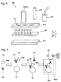
Fig. 13 is a diagram illustrating a structure to remove a liquid adhering to magnetic particles. -
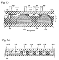
Fig. 14 is a diagram illustrating a state where the magnetic particles are transported by magnetic force. -
Fig. 15 is a diagram illustrating an example of an agitation operation using the magnetic force. -
Fig. 16 is a diagram illustrating another example of the agitation operation using the magnetic force. -
Fig. 17 is a cross-sectional view illustrating an air chamber and a valve. -
Fig. 18 is a plan view of a sample-R1 flow path. -
Fig. 19 is a cross-sectional view of the sample-R1 flow path. -
Fig. 20 is a plan view of a first flow path. -
Fig. 21 is a cross-sectional view of the first flow path. -
Fig. 22 is a schematic diagram of the first flow path when the cross-section perpendicular to the extending direction of the first flow path differs in the extending direction of the first flow path. -
Fig. 23 is a schematic diagram of the first flow path formed into a three-dimensionally intersecting shape. -
Fig. 24 is a schematic diagram illustrating another layout position of an R4 reagent tank. -
Fig. 25 is a schematic diagram illustrating an air chamber for transporting a third liquid to a dispersion portion by a negative pressure. -
Fig. 26 is another schematic diagram illustrating an air chamber for transporting the third liquid to the dispersion portion by the negative pressure. -
Fig. 27 is a plan view of an R5 reagent tank. -
Fig. 28 is a perspective view illustrating a connection portion between the R5 reagent tank and a detection tank. -
Fig. 29 is a plan view of the detection tank. -
Fig. 30 is a perspective view illustrating the sample analyzer. -
Fig. 31 is a schematic diagram illustrating a plunger unit. -
Fig. 32 is a schematic diagram illustrating heat blocks. - With reference to the drawings, an embodiment is described below.
- With reference to
Figs. 1 to 32 , description is given of a sample analyzingmethod using cartridge 100 and a configuration ofsample analysis cartridge 100 according to this embodiment. -
Fig. 1 is a diagram for explaining a sample analyzing method using sample analysis cartridge (hereinafter referred to as cartridge) 100 to be inserted intosample analyzer 500 for detectingdetection target substance 190a contained insample 190.Sample 190 is, for example, blood. -
Cartridge 100 includes firstliquid container 10, secondliquid container 20, andpassage 30 disposed between firstliquid container 10 and secondliquid container 20. Firstliquid container 10 contains a first liquid. The first liquid containsmagnetic particle 191 to be a support ofdetection target substance 190a. Secondliquid container 20 contains a second liquid. The second liquid contains labeledsubstance 193 which is to formcomplex 190c together withdetection target substance 190a andmagnetic particle 191. -
Passage 30 is connected toflow path 50. A portion offlow path 50 on the side opposite to the side connected topassage 30 is connected todetection tank 60 where to detectdetection target substance 190a.Cartridge 100 is configured such thatmagnetic particle 191 is transported todetection tank 60 where to detectdetection target substance 190a while being agitated in mixedliquid 190m ofcomplex 190c and a third liquid inflow path 50. The third liquid is, for example, a buffer solution. - A sample analyzing
method using cartridge 100 is described. - First,
magnetic particle 191 supportingdetection target substance 190a is transported from firstliquid container 10 to secondliquid container 20 by magnetic force throughpassage 30 between firstliquid container 10 and secondliquid container 20. The magnetic force for transportingmagnetic particle 191 withinpassage 30 is generated bymagnetic source 40, for example. - Next, complex 190c, which is formed in second
liquid container 20 and containsdetection target substance 190a,magnetic particle 191, and labeledsubstance 193, is transported to the third liquid inflow path 50. As a force that transports formed complex 190c to flowpath 50, the magnetic force can be used, which is generated bymagnetic source 40 insample analyzer 500, for example. - Then,
magnetic particle 191 is transported todetection tank 60 while being agitated in mixed liquid 190m of complex 190c and the third liquid withinflow path 50. - Various methods can be adopted as a method for agitating
magnetic particle 191 in mixed liquid 190m of complex 190c and the third liquid withinflow path 50. For example,magnetic particle 191 in mixed liquid 190m of complex 190c and the third liquid can be agitated withinflow path 50 by movingmixed liquid 190m with an air pressure. The use of the air pressure can dispersemagnetic particle 191 in mixed liquid 190m to be sufficiently agitated. - With the above configuration,
magnetic particle 191 can be transported todetection tank 60 while being agitated in mixed liquid 190m of complex 190c and the third liquid withinflow path 50. Thus,magnetic particle 191 agitated and dispersed inmixed liquid 190m can be transported todetection tank 60. As a result, luminescent reaction between labeledsubstance 193 contained inmixed liquid 190m andsubstrate 194 that is transported todetection tank 60 and facilitates light emission can be sufficiently caused indetection tank 60. Therefore, an adverse effect on detection accuracy ofdetection target substance 190a indetection tank 60 can be suppressed. -
Fig. 2 is a diagram illustrating an overview ofsample analyzer 500.Sample analyzer 500 can determine whether or not there isdetection target substance 190a in a specimen and can also determine the concentration of thedetection target substance 190a in the specimen.Sample analyzer 500 has a size that can be installed on a desk in an examination room where a doctor examines a patient, for example. The installation area ofsample analyzer 500 is as small as about 150 cm2 to 300 cm2, for example.Sample analyzer 500 is an apparatus for performing a test usingdisposable cartridge 100 to analyze a specimen. A liquid specimen, such as tissues, a body fluid, and a blood, obtained from the patient is injected intocartridge 100.Cartridge 100 having the specimen injected therein is inserted into setpart 550 insample analyzer 500. The specimen injected intocartridge 100 is analyzed by a predetermined assay based on functions ofcartridge 100 and functions ofsample analyzer 500. -
Fig. 3 is a diagram illustrating a configuration example ofcartridge 100.Cartridge 100 is formed into a flat plate shape.Cartridge 100 includesliquid containers 110 containing liquids such as a specimen, a reagent and a cleaning solution.Liquid containers 110 contain R1 to R5 reagents. Some of the reagents contain magnetic particle 191 (seeFig. 5 ) that reacts with a substance containingdetection target substance 190a (seeFig. 5 ). For example, the R2 reagent containsmagnetic particle 191.Cartridge 100 includes sample-R1 reaction tank 112 that stores a liquid obtained by mixing a specimen and the R1 reagent.Cartridge 100 includescleaning tank 113 that stores a cleaning solution for separating a reactant required for analysis ofdetection target substance 190a contained insample 190 from other substances.Cartridge 100 includesdetection tank 170 that stores a liquid containing a detection substance for detectingdetection target substance 190a. Note thatdetection tank 170 is described as an example ofdetection tank 60 illustrated inFig. 1 . The R2 reagent is an example of the first liquid. The R3 reagent is an example of the second liquid. The R4 reagent is an example of the third liquid. - Note that, in the present specification, the "thickness direction of
cartridge 100" is referred to as a Z direction. The front side in the Z direction is referred to as the Z1 size, while the back side in the Z direction is referred to as the Z2 side. - Note that, in the present specification, "to react" is a concept including "to couple" more than one substance.
- In
R2 reagent tank 111, sample-R1 reaction tank 112,cleaning tank 113, andR3 reagent tank 114,magnetic particle 191 is transported between the respective liquid containers, thereby progressing the reaction required for the analysis ofsample 190. The specimen is put intoblood cell separator 120 incartridge 100 .Blood cell separator 120 joins sample-R1 flow path 140 throughsample inflow path 123a.Cartridge 100 includesair chambers 130. Air sent fromair chambers 130 transports the liquids in some ofliquid containers 110 incartridge 100.Air chambers 130 are covered withsheet 133 made of an elastic member such as a rubber sheet.Air chambers 130 includefirst air chamber 130b.Air chambers 130 may also includeair chamber 130a andsecond air chamber 130c. -
Fig. 4 illustrates a configuration example ofsample analyzer 500.Sample analyzer 500 includes heat blocks 510,magnet 520,plunger 530, anddetector 540. Note thatmagnet 520 is described as an example ofmagnetic source 40 illustrated inFig. 1 . - Heat blocks 510 adjust the temperature of
cartridge 100. Heat blocks 510 may be disposed so as to come into contact with the upper and lower surfaces ofcartridge 100. Note that the upper surface ofcartridge 100 is a surface corresponding to the direction in whichmagnet 520 for transportingmagnetic particle 191 is disposed. - In
sample analyzer 500, magnetic particle 191 (seeFig. 5 ) contained in some ofliquid containers 110 incartridge 100 is transported by magnetic force ofmagnet 520.Magnet 520 is a permanent magnet, for example.Magnet 520 is formed into an approximately cylindrical shape, for example. - In
sample analyzer 500,plunger 530 can push down sheet 133 (seeFig. 3 ) coveringair chambers 130 incartridge 100.Air chambers 130 are contracted by pushing downsheet 133.Sample analyzer 500 can control the amount of air sent fromair chambers 130 by adjusting how much the air chambers are pushed down byplunger 530.Sample analyzer 500 can adjust the amount of the liquids to be transported, by controlling the air amount. Insample analyzer 500,air chambers 130 can be returned to their initial state bysheet 133 returningplunger 530 that is pushed down. A negative pressure is generated whenair chambers 130 are returned to the initial state.Sample analyzer 500 can transport the transported liquid in an opposite direction by the negative pressure. Some of the liquids incartridge 100 are moved back and forth in a flow path insidecartridge 100 by the vertical movement ofplunger 530. -
Heat block 510 includesholes 511 formagnet 520 andplunger 530 to accesscartridge 100.Holes 511 are provided inheat block 510 disposed on the upper surface ofcartridge 100, for example. Whenmagnet 520 andplunger 530access cartridge 100 from both directions, holes 511 may be provided in both of heat blocks 510 disposed on the both sides ofcartridge 100 in the Z direction. Some ofholes 511 may be recesses that do not penetrateheat block 510. -
Detector 540 detects light generated by a reactant generated by reaction betweensample 190 and a reagent.Detector 540 is, for example, a photomultiplier tube. - With reference to
Fig. 5 , an overview of assay is described. -
Detection target substance 190a insample 190 includes, for example, an antigen or an antibody. The antigen is a hepatitis B surface antigen (HBsAg), for example. - The R1 reagent contains
capture substance 192 to be coupled todetection target substance 190a. The R1 reagent can be selected according todetection target substance 190a.Capture substance 192 includes an antibody or an antigen. The antibody is a biotin-coupled HBs monoclonal antibody, for example. -
Detection target substance 190a coupled to capturesubstance 192 is coupled tomagnetic particle 191 in the R2 reagent.Magnetic particle 191 serves as a support ofdetection target substance 190a.Magnetic particle 191 is, for example, a streptavidin-coupled magnetic particle having its surface coated with avidin. The avidin ofmagnetic particle 191 is likely to be coupled to the biotin of the R1 reagent. Thus, connectivity betweenmagnetic particle 191 and capturesubstance 192 is improved. - The coupled body of
detection target substance 190a, capturesubstance 192, andmagnetic particle 191 is separated from an unreacted substance by cleaning with a cleaning solution. - After the cleaning, the coupled body of
detection target substance 190a, capturesubstance 192, andmagnetic particle 191 reacts with labeledsubstance 193 in the R3 reagent. Labeledsubstance 193 includes, for example, a labeled antibody. The labeled antibody is an ALP labeled HBsAg monoclonal antibody. - Labeled
substance 193 is coupled todetection target substance 190a, for example. Labeledsubstance 193 may be coupled to capturesubstance 192 or may be coupled tomagnetic particle 191. - A reactant obtained by reacting at least
detection target substance 190a andmagnetic particle 191 with labeledsubstance 193 is called "complex 190c". Complex 190c may containcapture substance 192, for example. - Complex 190c is separated from the unreacted substance by cleaning with the cleaning solution.
- After the cleaning, complex 190c is combined with the R4 reagent. A reactant obtained by reacting complex 190c with the R4 reagent is called "
mixed liquid 190m". The R4 reagent has a composition that facilitates light emission by complex 190c. The R4 reagent is, for example, a buffer solution. - The R5 reagent is added to
mixed liquid 190m. The R5 reagent includes, for example,substrate 194 that reacts with complex 190c to facilitate light emission. - Complex 190c reacts with the R5 reagent to emit light.
Detector 540 measures emission intensity of the light emitted by complex 190c. - Note that
detection target substance 190a, capturesubstance 192,magnetic particle 191, and labeledsubstance 193 may be a combination other than the above. For example,detection target substance 190a, capturesubstance 192,magnetic particle 191, and labeledsubstance 193 may be a TP antibody, a biotin-coupled TP antigen, a streptavidin-coupled magnetic particle, and an ALP labeled TP antigen, respectively. Alternatively,detection target substance 190a, capturesubstance 192,magnetic particle 191, and labeledsubstance 193 may be an HCV antibody, a biotin-coupled HCV antigen, an HCV antigen immobilized magnetic particle, and an ALP labeled anti-human IgG monoclonal antibody, respectively. Alternatively,detection target substance 190a, capturesubstance 192,magnetic particle 191, and labeledsubstance 193 may be an FT4, a biotin-coupled anti-T4 monoclonal antibody, a streptavidin-coupled magnetic particle, and an ALP labeled T3, respectively. - Alternatively,
detection target substance 190a may be any of an HIV-1p24 antigen and an anti-HIV antibody.Capture substance 192 may be a biotin-coupled anti-HIV-1p24 antibody.Magnetic particle 191 may be a coupled magnetic particle having streptavidin and immobilized HIV antigen. Labeledsubstance 193 may be any of an ALP labeled HIV-1p24 antibody and an ALP labeled HIV antigen. - With reference to
Figs. 3 to 7 , description is given of an operation example when the above assay is executed usingsample analyzer 500 andcartridge 100. - In Step S1,
cartridge 100 is opened from a package by a user. - In Step S2, a specimen obtained from a patient is put into
blood cell separator 120 in the openedcartridge 100. After the specimen is put intocartridge 100,cartridge 100 is inserted intosample analyzer 500. The specimen put intocartridge 100 stops after flowing fromblood cell separator 120 up to a location in sample-R1 flow path 140 near sample-R1 reaction tank 112. - In Step S3, heat blocks 510 (see
Fig. 4 ) adjust the temperature of the insertedcartridge 100. For example, heat blocks 510 heat upcartridge 100. - In Step S4,
sample analyzer 500 reacts the antigen contained indetection target substance 190a with the antibody contained in the R1 reagent.Sample analyzer 500 uses plunger 530 (seeFig. 4 ) to push downair chamber 130a. The R1 reagent is pushed out to sample-R1 flow path 140, through which the specimen flows, by the air sent fromair chamber 130a.Sample analyzer 500 moves up and downplunger 530. The specimen and the R1 reagent are moved back and forth within the flow path by a negative pressure and a positive pressure, which are alternately generated according to the up-and-down movement ofplunger 530. The back-and-forth movement within the flow path facilitates the reaction betweendetection target substance 190a and capturesubstance 192.Sample analyzer 500 further pushes downplunger 530 to push out the specimen and the R1 reagent to sample-R1 reaction tank 112. - In S5,
sample analyzer 500 reactsdetection target substance 190a and capturesubstance 192 withmagnetic particle 191 contained in the R2 reagent.Sample analyzer 500 usesmagnet 520 to drawmagnetic particle 191 close to the liquid surface inR2 reagent tank 111.Sample analyzer 500 uses the magnetic force ofmagnet 520 to transport the drawnmagnetic particle 191 fromR2 reagent tank 111 to sample-Rl reaction tank 112.Sample analyzer 500 uses the magnetic force ofmagnet 520 to agitatemagnetic particle 191, thereby reactingmagnetic particle 191 withdetection target substance 190a and capturesubstance 192. Note thatR2 reagent tank 111 is described as an example of firstliquid container 10 illustrated inFig. 1 . - In S6,
sample analyzer 500 uses the magnetic force ofmagnet 520 to transportmagnetic particle 191 reacted withdetection target substance 190a and capturesubstance 192 tocleaning tank 113.Sample analyzer 500 agitatesdetection target substance 190a and capturesubstance 192 as well asmagnetic particle 191 incleaning tank 113.Magnetic particle 191 reacted withdetection target substance 190a and capturesubstance 192 is separated from an unreacted substance. - In S7,
sample analyzer 500 uses the magnetic force ofmagnet 520 to transportmagnetic particle 191 reacted withdetection target substance 190a and capturesubstance 192 toR3 reagent tank 114.Sample analyzer 500 agitatesmagnetic particle 191 reacted withdetection target substance 190a and capturesubstance 192. Thus,magnetic particle 191 reacted withdetection target substance 190a and capturesubstance 192 reacts with labeledsubstance 193 contained in the R3 reagent, thereby generating complex 190c containingcapture substance 192. Note thatR3 reagent tank 114 is described as an example of secondliquid container 20 illustrated inFig. 1 . - In S8,
sample analyzer 500 uses the magnetic force ofmagnet 520 to transport complex 190c containingcapture substance 192 to the cleaning tank.Sample analyzer 500 agitates complex 190c containingcapture substance 192 incleaning tank 113. Thus, complex 190c containingcapture substance 192 is separated from an unreacted substance. - In S9,
sample analyzer 500 uses the magnetic force ofmagnet 520 to transport complex 190c containingcapture substance 192 toR4 reagent tank 151c. Complex 190c containingcapture substance 192 is combined with a buffer solution inR4 reagent tank 151c.Sample analyzer 500 usesplunger 530 to push downfirst air chamber 130b. Thus, mixed liquid 190m of complex 190c containingcapture substance 192 and the R4 reagent is pushed out tofirst flow path 150.Sample analyzer 500 moves up and downplunger 530, thereby movingmixed liquid 190m back and forth infirst flow path 150.Sample analyzer 500 further pushes downplunger 530 to push out mixed liquid 190m todetection tank 170. Note thatfirst flow path 150 is described as an example offlow path 50 illustrated inFig. 1 . - In Step S10,
substrate 194 contained in the R5 reagent is added tomixed liquid 190m.Sample analyzer 500 usesplunger 530 to push downsecond air chamber 130c, thereby pushing out the R5 reagent todetection tank 170. The R5 reagent pushed out todetection tank 170 is added tomixed liquid 190m indetection tank 170. - In Step S11,
detector 540 detects light generated by the reaction betweensubstrate 194 and labeledsubstance 193 contained inmixed liquid 190m.Detector 540 measures emission intensity of the light, for example. - In Step S12,
cartridge 100 is taken out ofsample analyzer 500 by the user and discarded upon completion of the measurement.Cartridge 100 to be discarded generates no waste liquid. - At least some of
liquid containers 110 illustrated inFig. 3 have a structure to suppress mixing of the liquid disposed in the surface ofliquid container 110 and the liquid disposed in the surface of anotherliquid container 110. - In this embodiment,
R2 reagent tank 111, sample-R1 reaction tank 112,cleaning tank 113,R3 reagent tank 114, andR4 reagent tank 151c have the structure to suppress mixing of the liquid inliquid container 110 and the liquid in anotherliquid container 110.R2 reagent tank 111, sample-R1 reaction tank 112,cleaning tank 113,R3 reagent tank 114, andR4 reagent tank 151c are connected in series through a gas-phase space inpassage 116.Passage 116 includespassage 30 illustrated inFig. 1 . - Note that the gas-phase space means a space filled with gas, through which
magnetic particle 191 invariably passes whenmagnetic particle 191 is transported from the liquid in one ofliquid containers 110 to the liquid inliquid container 110 adjacent thereto. Note that the inside ofpassage 116 may be entirely set as the gas-phase space or may be partially set as the gas-phase space. To be more specific, a part of a transportation path ofmagnetic particle 191 inpassage 116 between two adjacentliquid containers 110 may be set as the gas-phase space. Note that, as for the gas, air is preferably used, but nitrogen or the like can also be used. -
Sample analyzer 500 executes the assay by transportingmagnetic particle 191 through the gas-phase space inpassage 116 betweenliquid containers 110. Thus,sample analyzer 500 can execute the assay for analysis while suppressing the liquid inliquid container 110 from being mixed into the liquid inliquid container 110 adjacent thereto by the movement ofmagnetic particle 191. When the liquid contained inliquid container 110 is mixed into the liquid contained in anotherliquid container 110 by the movement ofmagnetic particle 191, reaction conditions change in the liquid in anotherliquid container 110. Such a change in reaction conditions reduces a reaction effect of the sample and the substance in the reagent. As a result, there may be influence on accuracy and the like of the measurement result obtained bysample analyzer 500. Therefore, the analysis accuracy ofsample analyzer 500 is improved by suppressing mixing of the liquid contained inliquid container 110 into the liquid contained in anotherliquid container 110. Moreover, it is no longer required to consider the compatibility between the liquids contained inliquid containers 110 by suppressing the mixing of the liquid contained inliquid container 110 into the liquid contained in anotherliquid container 110. Thus, the degree of freedom of selection of the liquids contained inliquid containers 110 is increased. As a result, combinations of reagents corresponding to various test items can be contained inliquid containers 110. Since various combinations of reagents can be contained inliquid containers 110, the type of the cartridge can be diversified. - Meanwhile, at least some of
liquid containers 110 have a liquid storage portion communicated with a surface region connected topassage 116 through an opening. More specifically,liquid container 110 may haveliquid storage part 211 having passage-side opening 211a and having a recessed shape capable of storing a liquid inside. In this embodiment,R2 reagent tank 111,cleaning tank 113,R3 reagent tank 114, andR4 reagent tank 151c each haveliquid storage part 211. As illustrated inFig. 7 ,step 216 is provided aroundopening 211a. The liquid contained inliquid container 110 may be not only inliquid storage part 211 but also inpassage 116 aboveliquid container 110. -
Magnetic particle 191 transported fromliquid container 110 throughpassage 116 can be moved intoliquid storage part 211 from passage-side opening 211a.Liquid storage part 211 can easily increase the amount of liquid. Thus, compared with the case wheremagnetic particle 191 is dispersed into the liquid disposed only in the surface ofliquid container 110,magnetic particle 191 can be dispersed efficiently into the liquid. -
Fig. 8 illustrates a layout example ofliquid containers 110 andpassage 116 connecting adjacentliquid containers 110. In the example illustrated inFig. 8 ,passage 116 is disposed aboveliquid containers 110.Magnetic particle 191 is pulled up to the gas-phase space inpassage 116 by the magnetic force fromliquid container 110, and transported to anotherliquid container 110. - As illustrated in
Fig. 9 ,passage 116 is provided near the outer surface ofcartridge 100, and is formed along the outer surface ofcartridge 100. In this case,magnet 520 insample analyzer 500 disposed outsidecartridge 100 can come close topassage 116. Thus, stronger magnetic force can be generated to act onmagnetic particle 191 for efficient transportation ofmagnetic particle 191. Moreover, the magnetic force to be generated bymagnet 520 can be reduced for howclose magnet 520 can come topassage 116. Thus,magnet 520 can be reduced in size, andsample analyzer 500 can also be reduced in size. - Step 216 around
opening 211a is disposed so as to separate oneliquid container 110 from anotherliquid container 110. Step 216 is disposed so as to separateliquid containers 110 frompassage 116. - In this embodiment, the liquids in different
liquid containers 110 can be inhibited from being mixed with each other through the gas-phase space inpassage 116. As a result, contamination betweenliquid containers 110 can be suppressed. - Step 216 is provided at the end of
liquid container 110. Also, step 216 is provided along the periphery ofopening 211a, for example. When opening 211a is circular,step 216 may be formed into an annular shape surrounding the peripheral part ofopening 211a. -
Cartridge 100 includescover part 117 on the Z1 side, which coversliquid containers 110 andpassage 116. Coverpart 117 sandwiches the liquids between liquid containers and coverpart 117. Coverpart 117 comes into contact with the upper surface of the liquid inpassage 116 aboveliquid container 110. Moreover,cartridge 100 has the Z2-side surface covered withsheet 102. - In the configuration example of
Fig. 7 , coverpart 117 coverspassage 116 from the upper surface side. - Cover
part 117 includes a flat sheet member, for example. Coverpart 117 may be formed using a material having a hydrophobic surface on theliquid container 110 side. The hydrophobic material may be a coating material provided on the surface of the sheet member ofcover part 117. The sheet member itself included incover part 117 may be formed using a hydrophobic material. Cartridgemain body 100a may be formed such that cartridgemain body 100a has a hydrophobic surface on the Z1 side. -
Fig. 9 is a diagram illustrating the liquid containers as seen from above. Step 216 is provided at passage-side opening 211a inliquid container 110. Step 216 is provided along the outer shape of passage-side opening 211a, for example. Step 216 is formed between passage-side opening 211a and a peripheral part of passage-side opening 211a. -
Fig. 9 illustrates the example where twosteps 216 are provided. However, the number ofsteps 216 can be changed as appropriate. -
Fig. 10 illustrates a configuration example of sample-R1 reaction tank 112. Incartridge 100, the specimen flowing in fromblood cell separator 120 is mixed with the R1 reagent on a flow path, and then discharged to sample-R1 reaction tank 112. - Sample-
R1 reaction tank 112 includesinlet 213 for supplying the mixed liquid of the specimen and the R1 reagent to the inside of the tank.Inlet 213 is disposed in a peripheral portion ofliquid disposition position 210.Fig. 10 illustrates a configuration example whereliquid disposition position 210 extends linearly in the X direction. In this case,inlet 213 is disposed at the end ofliquid disposition position 210.Inlet 213 is an opening formed in the surface (bottom) ofliquid disposition position 210, for example. Note that, in the present specification, the "longitudinal direction ofcartridge 100" is referred to as the X direction. Moreover, the "short direction ofcartridge 100" is referred to as the Y direction. - In the configuration example of
Fig. 10 , the mixed liquid of the specimen and the R1 reagent flowing in throughinlet 213 spreads in the X1 direction frominlet 213 that is one end ofliquid disposition position 210 to the other end. - At
liquid disposition position 210, the mixed liquid of the specimen and the R1 reagent spreads acrossliquid disposition position 210. Thus, the area of the mixed liquid of the specimen and the R1 reagent transported to sample-R1 reaction tank 112 is increased to facilitate mixing ofdetection target substance 190a in the mixed specimen and capturesubstance 192 in the R1 reagent withmagnetic particle 191. -
Fig. 11 illustrates another configuration example of sample-R1 reaction tank 112. - Sample-
R1 reaction tank 112 may have a shape other than the linearly extending shape. Here, sample-R1 reaction tank 112 has approximately circular liquid disposition position210.Inlet 213 is disposed in the surface of a peripheral portion ofliquid disposition position 210. - As illustrated in
Fig. 12 ,cleaning tank 113 is disposed between reagent tanks for reactingmagnetic particle 191 with the reagents, which are transported by the magnetic force. With such arrangement ofcleaning tank 113,magnetic particle 191 is transported to a next reagent tank after cleaned incleaning tank 113. Thus, carryover of unreacted substances to the next reagent tank can be suppressed.Cleaning tanks 113 may be arranged between the reagent tanks. For example,cleaning tank 113a andcleaning tank 113b are between sample-R1 reaction tank 112 andR3 reagent tank 114, andcleaning tank 113c is betweenR3 reagent tank 114 andR4 reagent tank 151c. -
Cleaning tanks 113a to 113c may be configured to includeliquid storage part 211 having passage-side opening 211a. In this case, the cleaning solution inliquid storage part 211 can be connected to the cleaning solution disposed above passage-side opening 211a through passage-side opening 211a. Thus,magnetic particle 191 transported by the magnetic force can be dispersed into the cleaning solution inliquid storage part 211 through passage-side opening 211a. As a result, the amount of the cleaning solution into whichmagnetic particle 191 is dispersed can be increased. Thus, cleaning efficiency can be improved. - Note that, in this embodiment,
magnetic particle 191 is transported through the gas-phase space. Thus, there is very little carryover of the liquid adhering tomagnetic particle 191 transported topassage 116. - As for
R3 reagent tank 114, for example, the same configuration as that of cleaningtanks 113a to 113c can be adopted. Whenliquid storage part 211 is provided inR3 reagent tank 114, the amount of the R3 reagent, into whichmagnetic particle 191 is dispersed, can be increased. Thus, reaction efficiency can be improved. - In this embodiment,
sample analyzer 500 transportsmagnetic particles 191 between the liquids disposed on the surfaces ofliquid containers 110. During the process of transportingmagnetic particles 191 between the liquids, the antibody, antigen and the like contained in the liquids adhere tomagnetic particles 191, and reaction required for the assay progresses. Thus, the liquid contained inliquid container 110 is inhibited from being mixed into the liquid contained in anotherliquid container 110 by the movement ofmagnetic particles 191. -
Fig. 13 illustrates an overview of the transportation ofmagnetic particles 191 betweenliquid containers 110. -
Sample analyzer 500 movesmagnet 520 close toliquid container 110 incartridge 100, thereby aggregatingmagnetic particles 191near opening 211a ofliquid container 110.Sample analyzer 500 movesmagnet 520 to transportmagnetic particles 191.Sample analyzer 500 movesmagnet 520 to transport the aggregatedmagnetic particles 191 to the gas-phase space inpassage 116 from a gas-liquid interface. The magnetic force ofmagnet 520 transports the aggregatedmagnetic particles 191 to the gas-phase space inpassage 116 from the gas-liquid interface.Sample analyzer 500further moves magnet 520 to transport aggregatedmagnetic particles 191 to the liquid in anotherliquid container 110. -
Liquid containers 110 associated with the transportation ofmagnetic particles 191 may be arranged linearly in the longitudinal direction ofcartridge 100. By linearly arrangingliquid containers 110,magnetic particles 191 can be inhibited from remaining inliquid containers 110 andpassage 116. - The liquid may adhere to
magnetic particles 191 transported topassage 116 from the gas-liquid interface. As illustrated inFig. 13 ,liquid containers 110 insample analysis cartridge 100 may have a structure to further suppress the liquid contained inliquid container 110 from being mixed into the liquid contained in anotherliquid container 110 by the movement ofmagnetic particles 191. For example,grooves 215 may be provided by deeply denting the surface ofpassage 116. Thus, a structure may be realized, in which the liquid adhering tomagnetic particles 191 is likely to fall onto the bottoms ofgrooves 215 frompassage 116. Moreover, the liquid may leak intogrooves 215 fromliquid containers 110. - The liquids in respective
liquid containers 110 may leak intopassage 116 throughopenings 211a as long as the amount of the liquid leaking intopassage 116 is not as large as that is mixed with the liquid in anotherliquid container 110 and the gas-phase space remains inpassage 116. In this case, even if the liquid leaks out topassage 116,magnetic particles 191 are transported to adjacentliquid container 110 through the gas-phase space inpassage 116. Thus, the liquid contained inliquid container 110 can be inhibited from being mixed into the liquid contained in anotherliquid container 110 by the movement ofmagnetic particles 191. When a structure is provided to further suppress the liquid contained inliquid container 110 from being mixed into the liquid contained in anotherliquid container 110 by the movement ofmagnetic particles 191, the liquid contained inliquid container 110 can be further inhibited from being mixed into the liquid contained in anotherliquid container 110 by the movement ofmagnetic particles 191. For example, when recessed grooves are provided inpassage 116, even if the liquid contained inliquid container 110 is mixed with the liquid contained in anotherliquid container 110 in the groove,magnetic particles 191 are transported to adjacentliquid container 110 through the gas-phase space inpassage 116. Thus, the liquid contained inliquid container 110 can be further inhibited from being mixed into the liquid contained in anotherliquid container 110 by the movement ofmagnetic particles 191. - Here, description is given of transportation of
magnetic particles 191 between two liquid containers. In a configuration example illustrated inFig. 14 ,magnetic particles 191 are transported by the magnetic force to sample-R1 reaction tank 112,cleaning tank 113a,cleaning tank 113b,R3 reagent tank 114,cleaning tank 113c, andR4 reagent tank 151c in this order, starting fromR2 reagent tank 111 on the upstream side in the transportation direction. -
Magnetic particles 191 transported fromR2 reagent tank 111 by the magnetic force are mixed withdetection target substance 190a and capturesubstance 192 in the R1 reagent in sample-R1 reaction tank 112. Sample-R1 reaction tank 112 contains a reaction liquid containingdetection target substance 190a,magnetic particles 191, and capturesubstance 192. - The liquid disposed in sample-
R1 reaction tank 112 is the reaction liquid containingdetection target substance 190a,magnetic particles 191, and capturesubstance 192. The liquid disposed incleaning tank 113a is a cleaning solution.Magnetic particles 191 supportingdetection target substance 190a are transported into the cleaning solution incleaning tank 113a bymagnet 520. - A cleaning solution is disposed in
cleaning tank 113b. Onlymagnetic particles 191 supportingdetection target substance 190a are transported by the magnetic force betweencleaning tank 113a andcleaning tank 113b. Therefore, the cleaning solution incleaning tank 113a can be inhibited from being brought intocleaning tank 113b. Thus, unwanted substances dispersed into the cleaning solution incleaning tank 113a can be inhibited from being transported tocleaning tank 113b. Thus, cleaning processing can be effectively performed. As a result, the number of times of the cleaning processing (that is, the number of the cleaning tanks) can be reduced. The unwanted substances include components other thandetection target substance 190a contained in the specimen, components unreacted withdetection target substance 190a contained in the reagent, and the like. -
R3 reagent tank 114 contains a labeled reagent containing labeledsubstance 193.Magnetic particles 191 supportingdetection target substance 190a are transported from cleaningtank 113b toR3 reagent tank 114. Then,detection target substance 190a reacts with labeledsubstance 193. -
Cleaning tank 113c contains a cleaning solution. Incleaning tank 113c,magnetic particles 191 supportingdetection target substance 190a are cleaned. BetweenR3 reagent tank 114 andcleaning tank 113c, again, the liquid can be inhibited from being brought fromR3 reagent tank 114 intocleaning tank 113c. Thus, the cleaning processing can be effectively performed by reducing brought unwanted substances. As a result, the unwanted substances can be inhibited from being transported todetection tank 170. Thus, reduction in detection accuracy can be effectively suppressed. -
R4 reagent tank 151c contains a buffer solution.Magnetic particles 191 transported from cleaningtank 113c toR4 reagent tank 151c is dispersed into the buffer solution inR4 reagent tank 151c. -
Figs. 15A to 15C illustrate an example of an agitation operation using the magnet. - In the agitation operation,
magnetic particles 191 are dispersed in the liquid by periodically changing the direction or strength of magnetic force acting onmagnetic particles 191, for example. In sample-R1 reaction tank 112, an agitation operation is performed to reactmagnetic particles 191,detection target substance 190a, and capturesubstance 192 with each other. - In
Fig. 15A ,sample analyzer 500 usesmagnet 520 to transportmagnetic particles 191 fromR2 reagent tank 111 to sample-R1 reaction tank 112.Sample analyzer 500 movesmagnet 520 close tocartridge 100 to transportmagnetic particles 191 in an aggregated state. - In
Fig. 15B ,sample analyzer 500 separatesmagnet 520 fromcartridge 100 to dispersemagnetic particles 191 in sample-R1 reaction tank 112. The agitation ofmagnetic particles 191 is facilitated by dispersingmagnetic particles 191 in sample-R1 reaction tank 112. - In
Fig. 15C ,sample analyzer 500 movesmagnet 520 separated fromcartridge 100 to agitate dispersedmagnetic particles 191.Sample analyzer 500 agitatesmagnetic particles 191 by movingmagnet 520 in the width direction or length direction ofcartridge 100 or in a circular orbit about an axis parallel to the Z direction. - By periodically repeating such operations,
magnetic particles 191 are dispersed in the liquid. Thus, the reaction can be efficiently progressed. In this embodiment,magnet 520 with strong magnetic force, such as a permanent magnet, is preferably used. Therefore, whencartridge 100 is close tomagnet 520,magnetic particles 191 are aggregated, inhibiting efficient agitation. As in the example illustrated inFig. 15B , the agitation ofmagnetic particles 191 can be facilitated by controlling the distance betweencartridge 100 andmagnet 520. -
Fig. 16 illustrates another agitation example according to this embodiment. -
Fig. 16A illustrates an agitation operation example inR3 reagent tank 114.Sample analyzer 500 movesmagnet 520 in the Z direction inR3 reagent tank 114. By movingmagnet 520 in the Z direction ofcartridge 100, labeledsubstance 193,detection target substance 190a,magnetic particles 191, and capturesubstance 192 are agitated in a depth direction ofR3 reagent tank 114. The agitation is facilitated entirely in the depth direction ofR3 reagent tank 114 rather than agitating only in the surface ofR3 reagent tank 114. -
Fig. 16B illustrates another agitation operation example inR3 reagent tank 114. In the example ofFig. 16B ,magnets 520 are disposed on the upper surface side and lower surface side ofcartridge 100, respectively.Sample analyzer 500moves magnets 520 on the upper surface side and lower surface side ofcartridge 100 in the thickness direction ofcartridge 100. In this case, the direction of the magnetic force acting onmagnetic particles 191 is alternately reversed in the thickness direction ofcartridge 100. Themagnets 520 on the both surfaces ofcartridge 100 are moved to further facilitate the agitation of the coupled body of labeledsubstance 193 and the magnetic particles. -
Figs. 17 and18 illustrate a configuration example ofair chamber 130. -
Air chamber 130 is connected tovalve part 131 and a portion of an air supply destination.Valve part 131 is connected toair chamber 130 andair flow path 132 connected to the outside ofcartridge 100, respectively. The air outside the cartridge is taken intoair chamber 130 fromair flow path 132 throughvalve part 131. -
Air chamber 130 andvalve part 131 have a structure for activation byplunger 530. For example,air chamber 130 andvalve part 131 are each formed into a recessed shape in the surface of cartridgemain body 100a so as to have an opening in the upper part thereof, and covered with sheet 133 (seeFig. 17 ) that is an elastic member.Valve part 131 can close the connection portion withair flow path 132 byplunger 530 entering the inside from the outside throughsheet 133.Air chamber 130 is filled with air.Air chamber 130 can discharge the internal air to the supply destination flow path byplunger 530 pushingsheet 133 intoair chamber 130 from the outside. -
Sample analyzer 500 discharges the air inair chamber 130 to the supply destination flow path by usingplunger 530 to closevalve part 131 and pushsheet 133 intoair chamber 130. Here, the operation of pushingsheet 133 intoair chamber 130 by usingplunger 530 is described as "activatingair chamber 130". The operation of pushingsheet 133 intovalve part 131 by usingplunger 530 is described as "closingvalve part 131". - In a state where
valve part 131 is not closed,air chamber 130 comes into contact with the air outside the cartridge throughvalve part 131 andair flow path 132. Whencartridge 100 is heated byheat blocks 510, the air inair chamber 130 expands. When the air inair chamber 130 expands, an increase in internal pressure ofair chamber 130 causes the air to flow out to the flow path of air supply destination. As a result, the liquid incartridge 100 may be unintentionally operated. A change in internal pressure due to the expansion of the air inair chamber 130 is suppressed byair chamber 130 coming into contact with the air outsidecartridge 100 throughair flow path 132. Thus, the liquid incartridge 100 can be inhibited from being unintentionally operated. -
Sample analyzer 500 may include the same number ofplungers 530 as those ofair chambers 130 andvalve parts 131 or may include a smaller number ofplunger 530 than those ofair chambers 130 andvalve parts 131. In such a case,air chambers 130 andvalve parts 131 to be activated may be switched by movingplungers 530. The sample analyzer can be reduced in size for the reduction in the number ofplungers 530. - When
plunger 530 is moved,air chambers 130 orvalve parts 131 can be arranged at various positions. For example, threeair chambers 130 are linearly arranged in the X direction, and threevalve parts 131 are linearly (seeFig. 3 ) arranged in the X direction. Accordingly,plunger 530 needs only be moved in the X direction. Thus, the movement mechanism can be simplified to reduce the size of the sample analyzer. -
Air chamber 130a andvalve part 131a illustrated inFig. 18 are provided to transport the specimen and the R1 reagent to sample-R1 reaction tank 112. InFig. 18 , oneair chamber 130a and onevalve part 131a are provided. However, more than oneair chamber 130a and more than onevalve part 131a may be provided. -
Air chamber 130a is connected to sample-R1 flow path 140.Valve part 131a is connected toair chamber 130a andair flow path 132. By closingvalve part 131a and activatingair chamber 130a, the specimen and R1 reagent flowing in fromblood cell separator 120 can be transported to sample-R1 reaction tank 112 from sample-R1 flow path 140. -
Cartridge 100 has a flow path structure that facilitates mixing of liquids on a flow path. - As illustrated in
Fig. 18 , sample-R1 flow path 140 includes, for example,R1 reagent tank 141,first portion 142,second portion 143, and mixingpart 144. -
R1 reagent tank 141 includes one end connected toair chamber 130a throughfirst portion 142.R1 reagent tank 141 includes the other end connected to sampleinflow path 123a throughsecond portion 143.R1 reagent tank 141 is provided to store the R1 reagent. The R1 reagent is, for example, an antibody that can be coupled to an antigen asdetection target substance 190a. - As illustrated in
Fig. 19 , in theR1 reagent tank 141,reagent storage portion 141a is formed near the bottom of cartridgemain body 100a in the Z direction. One side ofR1 reagent tank 141 is connected toair chamber 130a throughportion 141b extending in the Z direction. The other side ofR1 reagent tank 141 is connected tosecond portion 143 throughportion 141c extending in the Z direction.Portion 141b includes reduceddiameter part 141d on the opposite side to the bottom of cartridgemain body 100a.Portion 141c includes reduceddiameter part 141d on the opposite side to the bottom of cartridgemain body 100a. - Referring back to
Fig. 18 , mixingpart 144 includes one end connected to a joint portion betweensecond portion 143 andsample inflow path 123a connected toblood cell separator 120. Mixingpart 144 includes the other end connected to sample-R1 reaction tank 112. Mixingpart 144 includesstraight part 144a,bent part 144b, and meanderpart 144c. -
Straight part 144a partially overlaps withmeander part 144c as seen from the short direction ofcartridge 100.Straight part 144a includes narrowflow path part 144d, for example. Narrowflow path part 144d can stop the sample flowing fromblood cell separator 120. In this state, the R1 reagent is sent toward the specimen fromR1 reagent tank 141 by the air pressure inair chamber 130a. -
Bent part 144b connectsstraight part 144a to meanderpart 144c.Bent part 144b is formed into an approximately U-shape. In a schematic view, sample-R1 flow path 140 is bent approximately 180 degrees atbent part 144b. Thus, the movement distance of the specimen can be increased, and thus the specimen can be efficiently mixed. -
Meander part 144c is formed into a curved shape that enables efficient agitation of a specimen. In a planar view, for example, meanderpart 144c is schematically formed into a sine-wave shape. Thus, the specimen can be efficiently mixed by changing the flowing direction of the specimen. -
Meander part 144c includes dilatedparts 144e.Dilated parts 144e are formed by increasing the cross-sectional area ofmeander part 144c in a direction perpendicular to the flow path direction of the specimen.Dilated parts 144e are provided to accumulate the flow of the specimen and capture air bubbles generated in the specimen flowing through the flow path.Dilated parts 144e can further facilitate the mixing of the specimen by removing the air bubbles from the specimen flowing throughmeander part 144c. An arbitrary number of dilatedparts 144e can be provided. - Mixing
part 144 is connected to sample-R1 reaction tank 112 from the Z2 side ofcartridge 100, for example. Thus, the specimen and the R1 reagent can be transported to sample-R1 reaction tank 112 from below. - As illustrated in
Fig. 20 ,first flow path 150 is formed in a region betweenpassage 116 anddetection tank 170, and connectspassage 116 todetection tank 170.First flow path 150 includes, for example,dispersion portion 151,first portion 152, andsecond portion 153.First flow path 150 is provided to transport complex 190c containingdetection target substance 190a,magnetic particles 191, and labeledsubstance 193, which is formed inR3 reagent tank 114, to the R4 reagent. -
First air chamber 130b is connected to the upstream side ofR4 reagent tank 151c.Valve part 131b is connected tofirst air chamber 130b andair flow path 132. By closingvalve parts air chamber 130a andfirst air chamber 130b,mixed liquid 190m containing the R4 reagent and complex 190c can be transported todetection tank 170 throughfirst flow path 150.First air chamber 130b has the same configuration as that ofair chamber 130a, for example.Valve part 131b has the same configuration as that ofvalve part 131a, for example. - Mixed liquid 190m of complex 190c and the third liquid is transported through
first flow path 150 by the air pressure generated infirst air chamber 130b. The air pressure transportsmagnetic particles 191 while agitating the magnetic particles inmixed liquid 190m insidefirst flow path 150. Thus,magnetic particles 191 can be dispersed inmixed liquid 190m by using the air pressure. Thus,magnetic particles 191 can be sufficiently agitated. -
First air chamber 130b is configured to transportmagnetic particles 191 inmixed liquid 190m by the air pressure todetection tank 170 while agitating the magnetic particles infirst flow path 150. Thus,magnetic particles 191 can be transported todetection tank 170 while being sufficiently agitated. - By moving
mixed liquid 190m back and forth withinfirst flow path 150 by the air pressure,magnetic particles 191 are agitated withinmixed liquid 190m. Thus, the movement distance ofmixed liquid 190m can be increased for more efficient agitation. - For example, by alternately deforming
first air chamber 130b between an initial state and a contracted state,mixed liquid 190m is moved back and forth withinfirst flow path 150, andmagnetic particles 191 are agitated inmixed liquid 190m. Thus, the air pressure can be easily generated to efficiently agitatemagnetic particles 191 withinmixed liquid 190m. -
First air chamber 130b can be operated bysample analyzer 500.First air chamber 130b is configured to be deformed from the initial state to the contracted state by being pushed down byplunger 530. Thus, with a simpleoperation using plunger 530,first air chamber 130b can be deformed, andmixed liquid 190m can be moved back and forth withinfirst flow path 150. - The volume of
first flow path 150 is larger than the volume ofmixed liquid 190m. Thus,mixed liquid 190m can be easily moved back and forth infirst flow path 150. - As illustrated in
Fig. 21 ,dispersion portion 151 includespassage connection part 151a connected topassage 116 and firstportion connection part 151b connected tofirst portion 152.Passage connection part 151a is a portion wherepassage 116 joinsfirst flow path 150.Dispersion portion 151 includesR4 reagent tank 151c.R4 reagent tank 151c is formed near the bottom of cartridgemain body 100a in the Z direction.R4 reagent tank 151c contains the R4 reagent, for example. The R4 reagent is a buffer solution, for example. One side ofR4 reagent tank 151c is connected topassage connection part 151a throughportion 151d extending in the Z direction. The other side ofR4 reagent tank 151c is connected to firstportion connection part 151b throughportion 151e extending in the Z direction. Atportion 151d, reduceddiameter part 151f is formed on the opposite side to the bottom of cartridgemain body 100a. Atportion 151e, reduceddiameter part 151g is formed on the opposite side to the bottom of cartridgemain body 100a. -
Step 151h is formed on reduceddiameter part 151f. During sample analysis, a portion betweenstep 151h and coverpart 117 is filled with the R4 reagent. -
First portion 152 is disposed at a position lower thandetection tank 170 in the Z direction.First portion 152 has one end connected todispersion portion 151 and the other end connected tosecond portion 153.First portion 152 is formed so as to extend in the X direction and Y direction. Thus,magnetic particles 191 can be efficiently agitated by moving the magnetic particles in the X direction and Y direction withinfirst flow path 150 in mixed liquid 190m of complex 190c and the R4 reagent. -
Second portion 153 is disposed at a position lower thandetection tank 170 in the Z direction.Second portion 153 extends in the Z direction.Second portion 153 has one end connected tofirst portion 152 and the other end connected todetection tank 170.Second portion 153 can transport mixed liquid 190m of complex 190c and the R4 reagent todetection tank 170 from below. Thus, mixed liquid 190m of complex 190c and the R4 reagent can be inhibited from vigorously flowing in the horizontal direction indetection tank 170. As a result,mixed liquid 190m can be easily accumulated indetection tank 170. - Through
first flow path 150,mixed liquid 190m can be moved both up and down in the thickness direction ofcartridge 100 within the flow path. Thus,magnetic particles 191 inmixed liquid 190m can be efficiently agitated withinfirst flow path 150. - Referring back to
Fig. 20 , for example, at least a portion offirst flow path 150 is disposed on the extension ofpassage 116 in the transportation direction ofmagnetic particles 191 withinpassage 116. Thus, complex 190c containingmagnetic particles 191 and labeledsubstance 193 can be transported to the R4 reagent without changing the transportation direction ofmagnetic particles 191 transported withinpassage 116. -
First portion 152 is formed in a meandering shape, for example. As the meandering shape, a schematic sine-wave shape in a planar view can be adopted. By moving mixed liquid 190m of complex 190c and the R4 reagent in meanderingfirst portion 152,magnetic particles 191 are agitated inmixed liquid 190m. Since meanderingfirst portion 152 can complicate the flow ofmixed liquid 190m,magnetic particles 191 can be efficiently agitated withinmixed liquid 190m. - Alternatively,
first flow path 150 can also be configured as follows. - In an example illustrated in
Fig. 22 ,first portion 152 is formed such that the cross-section perpendicular to the extending direction offirst flow path 150 differs in the extending direction offirst flow path 150. Thus, since the cross-sectional area offirst flow path 150 can be changed according to the position, a flow rate infirst flow path 150 can be easily changed. As a result, unlike the case wherefirst flow path 150 is formed in the meandering shape,first flow path 150 can be formed in a compact size, andmagnetic particle 191 in mixed liquid 190m of complex 190c and the R4 reagent can be efficiently agitated withinfirst flow path 150. - In an example illustrated in
Fig. 23 ,first flow path 150 is formed so as to three-dimensionally intersect in a planar view, for example.First flow path 150 partially overlaps in the planar view. - In an example illustrated in
Fig. 24 ,R4 reagent tank 151c is disposed in a flow path portion connectingfirst air chamber 130b topassage 116. The R4 reagent is transported tofirst portion 152 by the air pressure infirst air chamber 130b. - In an example illustrated in
Fig. 25 ,R4 reagent tank 151c is disposed in liquid sendingpath 157 connected topassage 116, for example. In this case, liquid sendingpath 157 hasair hole 158 formed on the side opposite to the side connected topassage 116. Liquid sendingpath 157 is connected to the outside ofcartridge 100 throughair hole 158. Moreover,air chamber 130d is connected todetection tank 170.Air chamber 130d is connected toair flow path 132 throughvalve part 131d.Air chamber 130d has the same configuration as that ofair chamber 130a, for example.Valve part 131d has the same configuration as that ofvalve part 131a. In this example, a negative pressure generated by deformingair chamber 130d transports the R4 reagent tofirst portion 152. Moreover,magnetic particle 191 is agitated by the air pressure inair chamber 130d and transported todetection tank 170 inmixed liquid 190m. - In an example illustrated in
Fig. 26 ,R4 reagent tank 151c is disposed on aline connecting passage 116 andfirst portion 152, for example. A negative pressure generated by deformingair chamber 130d connected todetection tank 170 agitatesmagnetic particle 191 inmixed liquid 190m.Mixed liquid 190m is agitated by the air pressure inair chamber 130d and transported todetection tank 170. - Next, details of
second flow path 160 are described. - As illustrated in
Fig. 27 ,second flow path 160 includes, for example,R5 reagent tank 161,first portion 162, andsecond portion 163. -
R5 reagent tank 161 has one end connected tosecond air chamber 130c throughfirst portion 162.R5 reagent tank 161 has the other end connected todetection tank 170 throughsecond portion 163.R5 reagent tank 161 is provided to store a fourth reagent. The fourth reagent is, for example, the R5 reagent. The R5 reagent containssubstrate 194 that facilitates light generation by reacting with complex 190c. -
Second air chamber 130c is connected tosecond flow path 160.Valve part 131c is connected tosecond air chamber 130c andair flow path 132. By closingvalve part 131c and activatingsecond air chamber 130c, the R5 reagent can be transported todetection tank 170 throughsecond flow path 160.Second air chamber 130c has the same configuration as that ofair chamber 130a, for example.Valve part 131c has the same configuration as that ofvalve part 131a, for example. - The R5 reagent is transported to
detection tank 170 by the air pressure insecond air chamber 130c. Thus, the R5 reagent can be efficiently mixed with complex 190c. -
R5 reagent tank 161 has basically the same configuration (seeFig. 19 ) as that ofR1 reagent tank 141. InR5 reagent tank 161,reagent storage portion 161a is formed near the bottom of cartridgemain body 100a in the Z direction, for example. One side ofR5 reagent tank 161 is connected tofirst portion 162 throughportion 161b extending in the Z direction. The other side ofR5 reagent tank 161 is connected tosecond portion 163 throughportion 161c extending in the Z direction. Atportion 161b, reduceddiameter part 161d is formed on the opposite side to the bottom of cartridgemain body 100a. Atportion 161c, reduced diameter part 161e is formed on the opposite side to the bottom of cartridgemain body 100a. - As illustrated in
Fig. 28 ,second portion 163 is connected todetection tank 170 from the back surface side ofcartridge 100, for example.Second portion 163 can transport the R5 reagent todetection tank 170 from below. Thus, the R5 reagent can be inhibited from vigorously flowing in the horizontal direction indetection tank 170. As a result, the R5 reagent can be easily accumulated indetection tank 170. - For example,
second portion 163 is connected to a portion ofdetection tank 170 near a portion wheresecond portion 153 offirst flow path 150 is connected todetection tank 170. Thus, the R5 reagent can be efficiently mixed withmixed liquid 190m transported todetection tank 170 fromfirst flow path 150. -
Detection tank 170 illustrated inFig. 28 is provided for optical measurement of mixed liquid 190m added with the R5 reagent. For example,detection tank 170 includesliquid storage part 171, flowcontrol wall 172,step 173,external region 174, andair channel 175. -
Liquid storage part 171 is formed to be concave toward the Z2 side from the Z1 side surface of cartridgemain body 100a.Liquid storage part 171 is provided to accumulatemixed liquid 190m transported fromfirst flow path 150.Liquid storage part 171 is provided to accumulate the R5 reagent transported fromsecond flow path 160. -
Flow control wall 172 protrudes fromliquid storage part 171.Flow control wall 172 is formed on the opposite side tosecond portion 163 ofsecond flow path 160 with respect tosecond portion 153 offirst flow path 150.Flow control wall 172 is tilted towardsecond portion 163 ofsecond flow path 160 in a planar view. Moreover, flowcontrol wall 172 is linearly formed in the planar view, for example. - Step 173 is formed of a portion higher than
external region 174. Step 173 is disposed along the periphery ofliquid storage part 171. Step 173 surroundsliquid storage part 171. Mixed liquid 190m added with the R5 reagent can be accumulated in a region insidestep 173 in a planar view by the surface tension generated bystep 173. -
External region 174 is a region outsidestep 173.External region 174 is firmed into an arc shape in the planar view. - As illustrated in
Fig. 29 ,air channel 175 is formed on the outside ofexternal region 174.Air channel 175 is formed to be concave toward the Z2 side from the Z1 side surface of cartridgemain body 100a.Air channel 175 is firmed into an arc shape in a planar view.Air channel 175 is provided with twoconnection parts 175a andhole part 175b. - Two
connection parts 175a are provided near portions wherefirst flow path 150 andsecond flow path 160 are connected toliquid storage part 171, respectively.Air channel 175 is connected toexternal region 174 throughconnection parts 175a.Air channel 175 is connected toair flow path 132 throughhole part 175b. - When
detection tank 170 is thus configured, the specimen accumulated in the region insidestep 173 by the surface tension pushes air bubbles intoair channel 175 even if the air bubbles are transported toliquid storage part 171 aftermixed liquid 190m is transported toliquid storage part 171 throughfirst flow path 150. Thus, the air bubbles can escape to the outside ofcartridge 100 throughair channel 175 andair flow path 132. Moreover, the air bubbles can also escape to the outside ofcartridge 100 throughair channel 175 andair flow path 132 when the air bubbles are transported toliquid storage part 171 after the R5 reagent is transported as the fourth regent toliquid storage part 171 throughsecond flow path 160. - Configurations of the respective parts in
sample analyzer 500 are described.Fig. 30 illustrates a configuration example ofsample analyzer 500. -
Cartridge 100 is held byheat block 510. In the configuration example ofFig. 30 ,magnet unit 501,plunger unit 502, anddetector 540 are arranged on the sides ofheat block 510. In the configuration example ofFig. 30 ,heat block 510 also serves as setpart 550 ofcartridge 100. However,heat block 510 and setpart 550 may be individually provided. -
Magnet unit 501 includes:magnet 520 as a magnetic source; andmovement mechanism 521 configured to movemagnet 520 relative tocartridge 100.Movement mechanism 521 can movemagnet 520 in a horizontal direction and in a vertical direction (thickness direction of cartridge 100). Whenliquid containers 110 are linearly arranged,movement mechanism 521 may horizontally move only in one straight axial direction along the arrangement direction of respectiveliquid containers 110. - When
magnets 520 are provided above and belowcartridge 100, twomagnet units 501 are disposed. In this case, the horizontally moving structure ofmovement mechanism 521 may be shared by twomagnet units 501. -
Plunger unit 502 includes, for example:plunger 530 that activatesair chamber 130 andvalve part 131; andmovement mechanism 531 that movesplunger 530 relative tocartridge 100.Movement mechanism 531 can move plunger 530 in the vertical direction. Whenair chamber 130 andvalve part 131 are linearly arranged,movement mechanism 531 may horizontally move only in one straight axial direction along the arrangement direction ofair chamber 130 andvalve part 131. When the same number ofplungers 530 as those ofair chambers 130 andvalve parts 131 are provided, the horizontal positions ofplungers 530 can be fixed. Thus,movement mechanism 531 may move only in the vertical direction. -
Detector 540 is disposed at a position close todetection tank 170 incartridge 100. -
Magnet 520 is configured to collect magnetic particles attip 520a, for example. - In the configuration example of
Fig. 17 , the liquid is transported by activatingair chamber 130 in a closed state ofvalve part 131. Thus,plunger 530 forair chamber 130 andplunger 530 forvalve part 131 may be configured so as to individually move up and down. - In an example illustrated in
Fig. 31 ,plunger 530a is a plunger for activatingair chamber 130, andplunger 530b is a plunger for opening and closingvalve part 131.Respective plungers block 532 -
Plunger 530a is fixed to holdingblock 532.Plunger 530b is attached to holding block 532 in a state of being movable up and down relative to holdingblock 532.Plunger 530b is provided with energizingmember 533 that energizesplunger 530b in a direction protruding from holdingblock 532. - Thus, when holding
block 532 is lowered towardcartridge 100,plunger 530b first closesvalve part 131. When holdingblock 532 is further lowered in this state, energizingmember 533 is compressed andplunger 530b is moved relative to holdingblock 532. Thus, the position ofplunger 530b can be maintained even if holdingblock 532 is moved. Therefore, by moving holdingblock 532 up and down in the closed state ofvalve part 131, plunger 530a can move the liquid back and forth within the flow path by moving up and down relative toair chamber 130. Moreover, by further lowering holdingblock 532, the liquid can be sent to the portion of supply destination from the flow path. - In this embodiment,
sample analyzer 500 controls the temperatures ofdetection target substance 190a and reagent incartridge 100 to those required in the assay.Sample analyzer 500 usesheat block 510 to control the temperatures ofdetection target substance 190a and reagent incartridge 100.Heat block 510 performs the temperature control using a heating wire or the like which generates heat with unillustrated power supply, for example. When not only heating but also cooling is required, a thermoelectric element such as a Peltier element, for example, is used asheat block 510. -
Fig. 32 illustrates a configuration example of the heat blocks according to this embodiment. Heat blocks 510 are disposed on the upper and lower surfaces ofcartridge 100, for example.Heat block 510 may be disposed on any one of the upper and lower surfaces ofcartridge 100. - Heat block 510 disposed on the lower surface of
cartridge 100 is configured to cover at least a fluid structure associated with the transportation ofmagnetic particles 191. In this embodiment, the fluid structure associated with the transportation ofmagnetic particles 191 is the portion includingR2 reagent tank 111, sample-R1 reaction tank 112,cleaning tank 113,R3 reagent tank 114, andpassage 116 provided betweenliquid containers 110. Heat block 510 disposed on the lower surface ofcartridge 100 may be configured to cover almost the entire lower surface ofcartridge 100. By covering almost the entire lower surface ofcartridge 100 withheat block 510, temperature control efficiency ofcartridge 100 is improved. - Heat block 510 disposed on the upper surface of
cartridge 100 hasholes 511 forplunger 530 andmagnet 520 to accesscartridge 100.Hole 511 forplunger 530 to accesscartridge 100 is provided at the position corresponding toair chamber 130 incartridge 100.Hole 511 formagnet 520 to accesscartridge 100 is extended in the longitudinal direction ofcartridge 100. The hole extended in the longitudinal direction ofcartridge 100 enablesmagnet 520 to be moved in the transportation direction ofmagnetic particles 191 while staying close tocartridge 100. - When
magnets 520 are disposed on the upper and lower surfaces ofcartridge 100, groove 512 can be provided inheat block 510 on the lower surface ofcartridge 100. - Heat block 510 on the lower surface of
cartridge 100 hasgroove 512 extending in the longitudinal direction ofcartridge 100.Sample analyzer 500 applies magnetic force tocartridge 100 by insertingmagnet 520 provided on the lower surface ofcartridge 100 intogroove 512. Groove 512 inheat block 510 does not penetrate heat block 510 from the lower surface to the upper surface. Thus, the magnetic force can be applied from the lower surface ofcartridge 100 without impairing the function to control the temperature on approximately the entire lower surface ofcartridge 100. - Since
groove 512 is not a through-hole, the magnetic force that can be applied tocartridge 100 is assumed to be reduced.Magnet 520 on the upper surface ofcartridge 100 is required to apply magnetic force having strength required to transportmagnetic particles 191. On the other hand,magnet 520 provided on the lower surface ofcartridge 100 contributes less to the transportation ofmagnetic particles 191. Thus, the magnetic force that can be applied tocartridge 100 may be relatively reduced. - Note that the embodiment disclosed herein is merely illustrative in all aspects and should not be recognized as being restrictive. The scope of the invention is defined by the scope of the claims rather than by the above description of the embodiment, and is intended to include the meaning equivalent to the scope of the claims and all modifications within the scope.
Claims (15)
- A sample analyzing method using a sample analysis cartridge inserted into a sample analyzer that detects a detection target substance contained in a sample, comprising:transporting a magnetic particle supporting the detection target substance by magnetic force from a first liquid container to a second liquid container through a passage disposed between the first and second liquid containers, the first liquid container storing a first liquid containing the magnetic particle to be a support of the detection target substance, the second liquid container storing a second liquid containing a labeled substance which is to form a complex together with the detection target substance and the magnetic particle;transporting the complex, which is formed in the second liquid container, and contains the detection target substance, the magnetic particle, and the labeled substance, to a third liquid in a flow path; andtransporting the magnetic particle to a detection tank where to detect the detection target substance, while agitating the magnetic particle in a mixed liquid of the complex and the third liquid within the flow path.
- The sample analyzing method using a sample analysis cartridge according to claim 1, wherein
the magnetic particle is transported while being agitated in the mixed liquid within the flow path by an air pressure. - The sample analyzing method using a sample analysis cartridge according to claim 1 or 2, wherein
the magnetic particle is agitated in the mixed liquid in such a way that the mixed liquid is moved back and forth within the flow path by an air pressure. - The sample analyzing method using a sample analysis cartridge according to any one of claims 1 to 3, wherein
the flow path meanders, and
the magnetic particle is agitated in the mixed liquid in such a way that the mixed liquid is moved in the meandering flow path. - The sample analyzing method using a sample analysis cartridge according to claim 4, wherein
the mixed liquid is moved within the flow path also in a thickness direction of the sample analysis cartridge. - The sample analyzing method using a sample analysis cartridge according to any one of claims 1 to 5, wherein
a fourth liquid containing a substrate that facilitates light emission by reacting with the complex is transported to the detection tank by an air pressure. - The sample analyzing method using a sample analysis cartridge according to claim 6, wherein
the fourth liquid is transported to a position in the detection tank near a position to which the mixed liquid is transported from the flow path. - A sample analysis cartridge to be inserted into a sample analyzer that detects a detection target substance contained in a sample, comprising:a first liquid container that stores a first liquid containing a magnetic particle to be a support of the detection target substance;a second liquid container that stores a second liquid containing a labeled substance which is to form a complex together with the detection target substance and the magnetic particle;a passage that is disposed between the first liquid container and the second liquid container, and that transports the magnetic particle supporting the detection target substance to the second liquid container by magnetic force; anda first flow path that transports the complex, which is formed in the second liquid container and contains the detection target substance, the magnetic particle, and the labeled substance, to a third liquid,wherein the magnetic particle is transported to a detection tank where to detect the detection target substance while being agitated in a mixed liquid of the complex and the third liquid in the first flow path.
- The sample analysis cartridge according to claim 8, wherein
the magnetic particle is transported while being agitated in the mixed liquid in the first flow path by an air pressure. - The sample analysis cartridge according to one of claims 8 and 9, further comprising:an air chamber that transports the magnetic particle to the detection tank while agitating the magnetic particle in the mixed liquid in the first flow path by an air pressure.
- The sample analysis cartridge according to claim 10, wherein
the air chamber is alternately deformed between an initial state and a contracted state, thereby moving the mixed liquid back and forth in the first flow path and agitating the magnetic particle in the mixed liquid. - The sample analysis cartridge according to any one of claims 8 to 11, wherein
the first flow path is formed in a meandering shape. - A sample analyzer that performs a sample analysis using a sample analysis cartridge including: a first liquid container that stores a first liquid containing a magnetic particle to be a support of a detection target substance; a second liquid container that stores a second liquid containing a labeled substance which is to form a complex together with the detection target substance and the magnetic particle; a passage that is disposed between the first liquid container and the second liquid container, and that transports the magnetic particle supporting the detection target substance to the second liquid container by magnetic force; and a flow path that transports the complex formed in the second liquid container, and contains the detection target substance, the magnetic particle, and the labeled substance, to a third liquid,
wherein the sample analysis is performed using the sample analysis cartridge in which the magnetic particle is transported from inside of the flow path to a detection tank where to detect the detection target substance, while being agitated in a mixed liquid of the complex and the third liquid within the flow path. - The sample analyzer according to claim 13, wherein
the sample analysis is performed using the sample analysis cartridge in which the magnetic particle is transported while being agitated in the mixed liquid within the flow path by an air pressure. - The sample analyzer according to one of claims 13 and 14, wherein
the sample analyzer operates an air chamber further included in the sample analysis cartridge, the air chamber being to a chamber that transports the magnetic particle to the detection tank while agitating the magnetic particle in the mixed liquid within the flow path by an air pressure.
Applications Claiming Priority (1)
| Application Number | Priority Date | Filing Date | Title |
|---|---|---|---|
| JP2015093515A JP6466775B2 (en) | 2015-04-30 | 2015-04-30 | Sample analysis method using sample analysis cartridge, sample analysis cartridge, and sample analyzer |
Publications (2)
| Publication Number | Publication Date |
|---|---|
| EP3093666A1 true EP3093666A1 (en) | 2016-11-16 |
| EP3093666B1 EP3093666B1 (en) | 2018-11-07 |
Family
ID=55628920
Family Applications (1)
| Application Number | Title | Priority Date | Filing Date |
|---|---|---|---|
| EP16162295.6A Active EP3093666B1 (en) | 2015-04-30 | 2016-03-24 | Sample analyzing method using sample analysis cartridge, sample analysis cartridge, and sample analyzer |
Country Status (4)
| Country | Link |
|---|---|
| US (1) | US9752989B2 (en) |
| EP (1) | EP3093666B1 (en) |
| JP (1) | JP6466775B2 (en) |
| CN (1) | CN106092715B (en) |
Families Citing this family (4)
| Publication number | Priority date | Publication date | Assignee | Title |
|---|---|---|---|---|
| JP6506094B2 (en) * | 2015-04-30 | 2019-04-24 | シスメックス株式会社 | Test substance detection method and sample analyzer |
| CN107290524B (en) * | 2017-06-08 | 2024-03-19 | 杭州遂真生物技术有限公司 | Immunodetection kit |
| US11698381B2 (en) * | 2018-05-30 | 2023-07-11 | Sepmag Systems, S.L. | Opto-magnetophoretic method for the detection of biological and chemical substance |
| CN114618419A (en) * | 2020-12-11 | 2022-06-14 | 深圳市帝迈生物技术有限公司 | Sample filling method, sample filling assembly and sample analyzer |
Citations (7)
| Publication number | Priority date | Publication date | Assignee | Title |
|---|---|---|---|---|
| US20080031787A1 (en) * | 2006-08-02 | 2008-02-07 | Industrial Technology Research Institute | Magnetic bead-based sample separating device |
| JP2009148735A (en) * | 2007-12-21 | 2009-07-09 | Sharp Corp | Microreaction channel chip and chemical reaction device using microbead |
| US20090227044A1 (en) * | 2006-01-26 | 2009-09-10 | Dosi Dosev | Microchannel Magneto-Immunoassay |
| WO2011045436A1 (en) * | 2009-10-16 | 2011-04-21 | Åmic AB | An assay method and devices involving the use of magnetic particles |
| WO2012041809A1 (en) * | 2010-09-29 | 2012-04-05 | Baden-Wuerttemberg Stiftung Ggmbh | Method of transporting magnetic particles |
| US8158008B2 (en) | 2006-12-29 | 2012-04-17 | Intel Corporation | Device and method for particle complex handling |
| US20150093815A1 (en) * | 2013-09-30 | 2015-04-02 | Gnubio, Inc. | Microfluidic cartridge devices and methods of use and assembly |
Family Cites Families (10)
| Publication number | Priority date | Publication date | Assignee | Title |
|---|---|---|---|---|
| JPH08240596A (en) * | 1995-03-07 | 1996-09-17 | Hitachi Ltd | Specimen measuring device |
| WO1998000231A1 (en) * | 1996-06-28 | 1998-01-08 | Caliper Technologies Corporation | High-throughput screening assay systems in microscale fluidic devices |
| KR20070037432A (en) * | 2004-01-15 | 2007-04-04 | 도꾸리쯔교세이호징 가가꾸 기쥬쯔 신꼬 기꼬 | Chemical analysis apparatus and method of chemical analysis |
| GB2436616A (en) * | 2006-03-29 | 2007-10-03 | Inverness Medical Switzerland | Assay device and method |
| US20100311186A1 (en) * | 2006-07-28 | 2010-12-09 | Biosite Incorporated | Devices and methods for performing receptor binding assays using magnetic particles |
| US8323568B2 (en) * | 2008-06-13 | 2012-12-04 | Honeywell International Inc. | Magnetic bead assisted sample conditioning system |
| WO2011123662A1 (en) * | 2010-03-31 | 2011-10-06 | Abbott Point Of Care, Inc. | Biologic fluid analysis system with sample motion |
| BR112014032304B1 (en) * | 2012-06-22 | 2022-05-10 | Zoetis Denmark Aps | Method and system for the quantitative or qualitative determination of a target component in a liquid sample, and microfluidic device |
| US9766166B2 (en) * | 2013-01-09 | 2017-09-19 | Wisconsin Alumni Research Foundation | Device and method incorporating a slideable lid for extracting a targeted fraction from a sample |
| JP2014198324A (en) * | 2013-03-29 | 2014-10-23 | ソニー株式会社 | Microfluidic channel and microfluidic device |
-
2015
- 2015-04-30 JP JP2015093515A patent/JP6466775B2/en active Active
-
2016
- 2016-03-24 EP EP16162295.6A patent/EP3093666B1/en active Active
- 2016-03-28 US US15/082,337 patent/US9752989B2/en active Active
- 2016-03-31 CN CN201610195597.9A patent/CN106092715B/en active Active
Patent Citations (7)
| Publication number | Priority date | Publication date | Assignee | Title |
|---|---|---|---|---|
| US20090227044A1 (en) * | 2006-01-26 | 2009-09-10 | Dosi Dosev | Microchannel Magneto-Immunoassay |
| US20080031787A1 (en) * | 2006-08-02 | 2008-02-07 | Industrial Technology Research Institute | Magnetic bead-based sample separating device |
| US8158008B2 (en) | 2006-12-29 | 2012-04-17 | Intel Corporation | Device and method for particle complex handling |
| JP2009148735A (en) * | 2007-12-21 | 2009-07-09 | Sharp Corp | Microreaction channel chip and chemical reaction device using microbead |
| WO2011045436A1 (en) * | 2009-10-16 | 2011-04-21 | Åmic AB | An assay method and devices involving the use of magnetic particles |
| WO2012041809A1 (en) * | 2010-09-29 | 2012-04-05 | Baden-Wuerttemberg Stiftung Ggmbh | Method of transporting magnetic particles |
| US20150093815A1 (en) * | 2013-09-30 | 2015-04-02 | Gnubio, Inc. | Microfluidic cartridge devices and methods of use and assembly |
Also Published As
| Publication number | Publication date |
|---|---|
| US9752989B2 (en) | 2017-09-05 |
| EP3093666B1 (en) | 2018-11-07 |
| CN106092715B (en) | 2019-03-19 |
| US20160320307A1 (en) | 2016-11-03 |
| JP6466775B2 (en) | 2019-02-06 |
| CN106092715A (en) | 2016-11-09 |
| JP2016211893A (en) | 2016-12-15 |
Similar Documents
| Publication | Publication Date | Title |
|---|---|---|
| US11656223B2 (en) | Method of detecting test substance, sample analysis cartridge, and sample analyzer | |
| EP3093666B1 (en) | Sample analyzing method using sample analysis cartridge, sample analysis cartridge, and sample analyzer | |
| JP3505689B2 (en) | Capsule chemical sample liquid analyzer and analysis method | |
| JP6937686B2 (en) | Liquid-sealed cartridge, sample analyzer, and sample analysis method | |
| JP6334112B2 (en) | Automatic analyzer | |
| CN105277727B (en) | Vitro diagnosis assays method and system | |
| JP2011013043A (en) | Magnetic particle transfer device and magnetic particle transfer method | |
| US5904899A (en) | Assaying apparatus and a vessel holder device in use with the assaying apparatus | |
| JPWO2016153000A1 (en) | Fluidic device, system and method | |
| JP5489283B2 (en) | Automatic analyzer | |
| JP2011013148A (en) | Automatic analyzer and magnetic particle moving method | |
| JP2006284323A (en) | Micro total analysis system | |
| JP2005043361A (en) | Improved fluid mixture in analyzer for diagnosis | |
| EP2466316B1 (en) | Fluidic systems, fluid containers and processes for washing fluid lines | |
| JP7157421B2 (en) | Fluid device | |
| US20190250183A1 (en) | Fluid control equipment for bio-reaction, bio-reaction system and fluid control method for bio-reaction | |
| JP2008224600A (en) | Reaction quantity measurement method | |
| US20060040403A1 (en) | System and method for providing a reaction using a limited reaction surface area | |
| JP4298616B2 (en) | Treatment tool | |
| JP4298617B2 (en) | Treatment tool | |
| JPWO2009139274A1 (en) | Micro inspection chip, inspection apparatus, and driving method of micro inspection chip |
Legal Events
| Date | Code | Title | Description |
|---|---|---|---|
| PUAI | Public reference made under article 153(3) epc to a published international application that has entered the european phase |
Free format text: ORIGINAL CODE: 0009012 |
|
| 17P | Request for examination filed |
Effective date: 20160324 |
|
| AK | Designated contracting states |
Kind code of ref document: A1 Designated state(s): AL AT BE BG CH CY CZ DE DK EE ES FI FR GB GR HR HU IE IS IT LI LT LU LV MC MK MT NL NO PL PT RO RS SE SI SK SM TR |
|
| AX | Request for extension of the european patent |
Extension state: BA ME |
|
| STAA | Information on the status of an ep patent application or granted ep patent |
Free format text: STATUS: EXAMINATION IS IN PROGRESS |
|
| 17Q | First examination report despatched |
Effective date: 20180309 |
|
| GRAP | Despatch of communication of intention to grant a patent |
Free format text: ORIGINAL CODE: EPIDOSNIGR1 |
|
| STAA | Information on the status of an ep patent application or granted ep patent |
Free format text: STATUS: GRANT OF PATENT IS INTENDED |
|
| INTG | Intention to grant announced |
Effective date: 20180717 |
|
| GRAS | Grant fee paid |
Free format text: ORIGINAL CODE: EPIDOSNIGR3 |
|
| GRAA | (expected) grant |
Free format text: ORIGINAL CODE: 0009210 |
|
| STAA | Information on the status of an ep patent application or granted ep patent |
Free format text: STATUS: THE PATENT HAS BEEN GRANTED |
|
| AK | Designated contracting states |
Kind code of ref document: B1 Designated state(s): AL AT BE BG CH CY CZ DE DK EE ES FI FR GB GR HR HU IE IS IT LI LT LU LV MC MK MT NL NO PL PT RO RS SE SI SK SM TR |
|
| REG | Reference to a national code |
Ref country code: GB Ref legal event code: FG4D |
|
| REG | Reference to a national code |
Ref country code: CH Ref legal event code: EP Ref country code: AT Ref legal event code: REF Ref document number: 1062695 Country of ref document: AT Kind code of ref document: T Effective date: 20181115 |
|
| REG | Reference to a national code |
Ref country code: DE Ref legal event code: R096 Ref document number: 602016006876 Country of ref document: DE |
|
| REG | Reference to a national code |
Ref country code: IE Ref legal event code: FG4D |
|
| REG | Reference to a national code |
Ref country code: NL Ref legal event code: MP Effective date: 20181107 |
|
| REG | Reference to a national code |
Ref country code: LT Ref legal event code: MG4D |
|
| REG | Reference to a national code |
Ref country code: AT Ref legal event code: MK05 Ref document number: 1062695 Country of ref document: AT Kind code of ref document: T Effective date: 20181107 |
|
| PG25 | Lapsed in a contracting state [announced via postgrant information from national office to epo] |
Ref country code: ES Free format text: LAPSE BECAUSE OF FAILURE TO SUBMIT A TRANSLATION OF THE DESCRIPTION OR TO PAY THE FEE WITHIN THE PRESCRIBED TIME-LIMIT Effective date: 20181107 Ref country code: LV Free format text: LAPSE BECAUSE OF FAILURE TO SUBMIT A TRANSLATION OF THE DESCRIPTION OR TO PAY THE FEE WITHIN THE PRESCRIBED TIME-LIMIT Effective date: 20181107 Ref country code: HR Free format text: LAPSE BECAUSE OF FAILURE TO SUBMIT A TRANSLATION OF THE DESCRIPTION OR TO PAY THE FEE WITHIN THE PRESCRIBED TIME-LIMIT Effective date: 20181107 Ref country code: NO Free format text: LAPSE BECAUSE OF FAILURE TO SUBMIT A TRANSLATION OF THE DESCRIPTION OR TO PAY THE FEE WITHIN THE PRESCRIBED TIME-LIMIT Effective date: 20190207 Ref country code: BG Free format text: LAPSE BECAUSE OF FAILURE TO SUBMIT A TRANSLATION OF THE DESCRIPTION OR TO PAY THE FEE WITHIN THE PRESCRIBED TIME-LIMIT Effective date: 20190207 Ref country code: FI Free format text: LAPSE BECAUSE OF FAILURE TO SUBMIT A TRANSLATION OF THE DESCRIPTION OR TO PAY THE FEE WITHIN THE PRESCRIBED TIME-LIMIT Effective date: 20181107 Ref country code: LT Free format text: LAPSE BECAUSE OF FAILURE TO SUBMIT A TRANSLATION OF THE DESCRIPTION OR TO PAY THE FEE WITHIN THE PRESCRIBED TIME-LIMIT Effective date: 20181107 Ref country code: AT Free format text: LAPSE BECAUSE OF FAILURE TO SUBMIT A TRANSLATION OF THE DESCRIPTION OR TO PAY THE FEE WITHIN THE PRESCRIBED TIME-LIMIT Effective date: 20181107 Ref country code: IS Free format text: LAPSE BECAUSE OF FAILURE TO SUBMIT A TRANSLATION OF THE DESCRIPTION OR TO PAY THE FEE WITHIN THE PRESCRIBED TIME-LIMIT Effective date: 20190307 |
|
| PG25 | Lapsed in a contracting state [announced via postgrant information from national office to epo] |
Ref country code: NL Free format text: LAPSE BECAUSE OF FAILURE TO SUBMIT A TRANSLATION OF THE DESCRIPTION OR TO PAY THE FEE WITHIN THE PRESCRIBED TIME-LIMIT Effective date: 20181107 Ref country code: SE Free format text: LAPSE BECAUSE OF FAILURE TO SUBMIT A TRANSLATION OF THE DESCRIPTION OR TO PAY THE FEE WITHIN THE PRESCRIBED TIME-LIMIT Effective date: 20181107 Ref country code: RS Free format text: LAPSE BECAUSE OF FAILURE TO SUBMIT A TRANSLATION OF THE DESCRIPTION OR TO PAY THE FEE WITHIN THE PRESCRIBED TIME-LIMIT Effective date: 20181107 Ref country code: PT Free format text: LAPSE BECAUSE OF FAILURE TO SUBMIT A TRANSLATION OF THE DESCRIPTION OR TO PAY THE FEE WITHIN THE PRESCRIBED TIME-LIMIT Effective date: 20190307 Ref country code: GR Free format text: LAPSE BECAUSE OF FAILURE TO SUBMIT A TRANSLATION OF THE DESCRIPTION OR TO PAY THE FEE WITHIN THE PRESCRIBED TIME-LIMIT Effective date: 20190208 Ref country code: AL Free format text: LAPSE BECAUSE OF FAILURE TO SUBMIT A TRANSLATION OF THE DESCRIPTION OR TO PAY THE FEE WITHIN THE PRESCRIBED TIME-LIMIT Effective date: 20181107 |
|
| PG25 | Lapsed in a contracting state [announced via postgrant information from national office to epo] |
Ref country code: DK Free format text: LAPSE BECAUSE OF FAILURE TO SUBMIT A TRANSLATION OF THE DESCRIPTION OR TO PAY THE FEE WITHIN THE PRESCRIBED TIME-LIMIT Effective date: 20181107 Ref country code: CZ Free format text: LAPSE BECAUSE OF FAILURE TO SUBMIT A TRANSLATION OF THE DESCRIPTION OR TO PAY THE FEE WITHIN THE PRESCRIBED TIME-LIMIT Effective date: 20181107 Ref country code: IT Free format text: LAPSE BECAUSE OF FAILURE TO SUBMIT A TRANSLATION OF THE DESCRIPTION OR TO PAY THE FEE WITHIN THE PRESCRIBED TIME-LIMIT Effective date: 20181107 Ref country code: PL Free format text: LAPSE BECAUSE OF FAILURE TO SUBMIT A TRANSLATION OF THE DESCRIPTION OR TO PAY THE FEE WITHIN THE PRESCRIBED TIME-LIMIT Effective date: 20181107 |
|
| REG | Reference to a national code |
Ref country code: DE Ref legal event code: R097 Ref document number: 602016006876 Country of ref document: DE |
|
| PG25 | Lapsed in a contracting state [announced via postgrant information from national office to epo] |
Ref country code: SM Free format text: LAPSE BECAUSE OF FAILURE TO SUBMIT A TRANSLATION OF THE DESCRIPTION OR TO PAY THE FEE WITHIN THE PRESCRIBED TIME-LIMIT Effective date: 20181107 Ref country code: SK Free format text: LAPSE BECAUSE OF FAILURE TO SUBMIT A TRANSLATION OF THE DESCRIPTION OR TO PAY THE FEE WITHIN THE PRESCRIBED TIME-LIMIT Effective date: 20181107 Ref country code: EE Free format text: LAPSE BECAUSE OF FAILURE TO SUBMIT A TRANSLATION OF THE DESCRIPTION OR TO PAY THE FEE WITHIN THE PRESCRIBED TIME-LIMIT Effective date: 20181107 Ref country code: RO Free format text: LAPSE BECAUSE OF FAILURE TO SUBMIT A TRANSLATION OF THE DESCRIPTION OR TO PAY THE FEE WITHIN THE PRESCRIBED TIME-LIMIT Effective date: 20181107 |
|
| PLBE | No opposition filed within time limit |
Free format text: ORIGINAL CODE: 0009261 |
|
| STAA | Information on the status of an ep patent application or granted ep patent |
Free format text: STATUS: NO OPPOSITION FILED WITHIN TIME LIMIT |
|
| 26N | No opposition filed |
Effective date: 20190808 |
|
| PG25 | Lapsed in a contracting state [announced via postgrant information from national office to epo] |
Ref country code: SI Free format text: LAPSE BECAUSE OF FAILURE TO SUBMIT A TRANSLATION OF THE DESCRIPTION OR TO PAY THE FEE WITHIN THE PRESCRIBED TIME-LIMIT Effective date: 20181107 Ref country code: MC Free format text: LAPSE BECAUSE OF FAILURE TO SUBMIT A TRANSLATION OF THE DESCRIPTION OR TO PAY THE FEE WITHIN THE PRESCRIBED TIME-LIMIT Effective date: 20181107 |
|
| REG | Reference to a national code |
Ref country code: CH Ref legal event code: PL |
|
| PG25 | Lapsed in a contracting state [announced via postgrant information from national office to epo] |
Ref country code: LU Free format text: LAPSE BECAUSE OF NON-PAYMENT OF DUE FEES Effective date: 20190324 |
|
| REG | Reference to a national code |
Ref country code: BE Ref legal event code: MM Effective date: 20190331 |
|
| PG25 | Lapsed in a contracting state [announced via postgrant information from national office to epo] |
Ref country code: CH Free format text: LAPSE BECAUSE OF NON-PAYMENT OF DUE FEES Effective date: 20190331 Ref country code: LI Free format text: LAPSE BECAUSE OF NON-PAYMENT OF DUE FEES Effective date: 20190331 Ref country code: IE Free format text: LAPSE BECAUSE OF NON-PAYMENT OF DUE FEES Effective date: 20190324 |
|
| PG25 | Lapsed in a contracting state [announced via postgrant information from national office to epo] |
Ref country code: BE Free format text: LAPSE BECAUSE OF NON-PAYMENT OF DUE FEES Effective date: 20190331 |
|
| PG25 | Lapsed in a contracting state [announced via postgrant information from national office to epo] |
Ref country code: TR Free format text: LAPSE BECAUSE OF FAILURE TO SUBMIT A TRANSLATION OF THE DESCRIPTION OR TO PAY THE FEE WITHIN THE PRESCRIBED TIME-LIMIT Effective date: 20181107 |
|
| PG25 | Lapsed in a contracting state [announced via postgrant information from national office to epo] |
Ref country code: MT Free format text: LAPSE BECAUSE OF NON-PAYMENT OF DUE FEES Effective date: 20190324 |
|
| PG25 | Lapsed in a contracting state [announced via postgrant information from national office to epo] |
Ref country code: CY Free format text: LAPSE BECAUSE OF FAILURE TO SUBMIT A TRANSLATION OF THE DESCRIPTION OR TO PAY THE FEE WITHIN THE PRESCRIBED TIME-LIMIT Effective date: 20181107 |
|
| PG25 | Lapsed in a contracting state [announced via postgrant information from national office to epo] |
Ref country code: HU Free format text: LAPSE BECAUSE OF FAILURE TO SUBMIT A TRANSLATION OF THE DESCRIPTION OR TO PAY THE FEE WITHIN THE PRESCRIBED TIME-LIMIT; INVALID AB INITIO Effective date: 20160324 |
|
| PG25 | Lapsed in a contracting state [announced via postgrant information from national office to epo] |
Ref country code: MK Free format text: LAPSE BECAUSE OF FAILURE TO SUBMIT A TRANSLATION OF THE DESCRIPTION OR TO PAY THE FEE WITHIN THE PRESCRIBED TIME-LIMIT Effective date: 20181107 |
|
| PGFP | Annual fee paid to national office [announced via postgrant information from national office to epo] |
Ref country code: FR Payment date: 20230208 Year of fee payment: 8 |
|
| PGFP | Annual fee paid to national office [announced via postgrant information from national office to epo] |
Ref country code: GB Payment date: 20230202 Year of fee payment: 8 Ref country code: DE Payment date: 20230131 Year of fee payment: 8 |