EP3217195A1 - Optical sensor - Google Patents
Optical sensor Download PDFInfo
- Publication number
- EP3217195A1 EP3217195A1 EP16159085.6A EP16159085A EP3217195A1 EP 3217195 A1 EP3217195 A1 EP 3217195A1 EP 16159085 A EP16159085 A EP 16159085A EP 3217195 A1 EP3217195 A1 EP 3217195A1
- Authority
- EP
- European Patent Office
- Prior art keywords
- optical sensor
- protective field
- sensor according
- protective
- switching
- Prior art date
- Legal status (The legal status is an assumption and is not a legal conclusion. Google has not performed a legal analysis and makes no representation as to the accuracy of the status listed.)
- Granted
Links
- 230000003287 optical effect Effects 0.000 title claims abstract description 82
- 230000001681 protective effect Effects 0.000 claims abstract description 117
- 238000001514 detection method Methods 0.000 claims abstract description 29
- 238000011156 evaluation Methods 0.000 claims abstract description 27
- 230000006399 behavior Effects 0.000 claims description 11
- 230000006870 function Effects 0.000 claims description 5
- 230000003213 activating effect Effects 0.000 claims description 3
- 230000007613 environmental effect Effects 0.000 claims description 3
- 238000012360 testing method Methods 0.000 claims description 3
- 238000005259 measurement Methods 0.000 description 3
- 238000000034 method Methods 0.000 description 3
- 238000012544 monitoring process Methods 0.000 description 3
- 230000004913 activation Effects 0.000 description 2
- 230000006978 adaptation Effects 0.000 description 1
- 230000005540 biological transmission Effects 0.000 description 1
- 238000010276 construction Methods 0.000 description 1
- 230000001419 dependent effect Effects 0.000 description 1
- 238000011161 development Methods 0.000 description 1
- 230000018109 developmental process Effects 0.000 description 1
- 238000005516 engineering process Methods 0.000 description 1
- 231100001261 hazardous Toxicity 0.000 description 1
- 230000000149 penetrating effect Effects 0.000 description 1
- 238000011076 safety test Methods 0.000 description 1
- 239000000523 sample Substances 0.000 description 1
Images

Classifications
-
- G—PHYSICS
- G01—MEASURING; TESTING
- G01V—GEOPHYSICS; GRAVITATIONAL MEASUREMENTS; DETECTING MASSES OR OBJECTS; TAGS
- G01V8/00—Prospecting or detecting by optical means
- G01V8/10—Detecting, e.g. by using light barriers
-
- F—MECHANICAL ENGINEERING; LIGHTING; HEATING; WEAPONS; BLASTING
- F16—ENGINEERING ELEMENTS AND UNITS; GENERAL MEASURES FOR PRODUCING AND MAINTAINING EFFECTIVE FUNCTIONING OF MACHINES OR INSTALLATIONS; THERMAL INSULATION IN GENERAL
- F16P—SAFETY DEVICES IN GENERAL; SAFETY DEVICES FOR PRESSES
- F16P3/00—Safety devices acting in conjunction with the control or operation of a machine; Control arrangements requiring the simultaneous use of two or more parts of the body
- F16P3/12—Safety devices acting in conjunction with the control or operation of a machine; Control arrangements requiring the simultaneous use of two or more parts of the body with means, e.g. feelers, which in case of the presence of a body part of a person in or near the danger zone influence the control or operation of the machine
- F16P3/14—Safety devices acting in conjunction with the control or operation of a machine; Control arrangements requiring the simultaneous use of two or more parts of the body with means, e.g. feelers, which in case of the presence of a body part of a person in or near the danger zone influence the control or operation of the machine the means being photocells or other devices sensitive without mechanical contact
- F16P3/144—Safety devices acting in conjunction with the control or operation of a machine; Control arrangements requiring the simultaneous use of two or more parts of the body with means, e.g. feelers, which in case of the presence of a body part of a person in or near the danger zone influence the control or operation of the machine the means being photocells or other devices sensitive without mechanical contact using light grids
-
- G—PHYSICS
- G01—MEASURING; TESTING
- G01S—RADIO DIRECTION-FINDING; RADIO NAVIGATION; DETERMINING DISTANCE OR VELOCITY BY USE OF RADIO WAVES; LOCATING OR PRESENCE-DETECTING BY USE OF THE REFLECTION OR RERADIATION OF RADIO WAVES; ANALOGOUS ARRANGEMENTS USING OTHER WAVES
- G01S17/00—Systems using the reflection or reradiation of electromagnetic waves other than radio waves, e.g. lidar systems
- G01S17/02—Systems using the reflection of electromagnetic waves other than radio waves
- G01S17/04—Systems determining the presence of a target
-
- G—PHYSICS
- G01—MEASURING; TESTING
- G01S—RADIO DIRECTION-FINDING; RADIO NAVIGATION; DETERMINING DISTANCE OR VELOCITY BY USE OF RADIO WAVES; LOCATING OR PRESENCE-DETECTING BY USE OF THE REFLECTION OR RERADIATION OF RADIO WAVES; ANALOGOUS ARRANGEMENTS USING OTHER WAVES
- G01S17/00—Systems using the reflection or reradiation of electromagnetic waves other than radio waves, e.g. lidar systems
- G01S17/02—Systems using the reflection of electromagnetic waves other than radio waves
- G01S17/06—Systems determining position data of a target
- G01S17/42—Simultaneous measurement of distance and other co-ordinates
Definitions
- the invention relates to an optical sensor according to the preamble of claim 1.
- optical sensors are often used for hazardous area protection on machines and equipment.
- An example of such optical sensors are scanning distance sensors, that is, area distance sensors, by means of which the apron of a machine, a vehicle or a plant is monitored.
- These area distance sensors have a distance sensor element which emits transmitted light beams for the detection of objects.
- the area distance sensor has a deflection unit, by means of which the transmitted light beams are deflected periodically within a surface. With the area distance sensor, objects can then be located within the detected area, i. there is a position determination of the objects.
- a protective field of a predetermined size is defined in the area distance sensor, which forms a section of the area swept by transmitted light beams. Then, the area distance sensor detects whether an object penetrates into the protective field. As soon as this is the case, an object detection signal is generated in the area distance sensor, which preferably leads to the decommissioning of the monitored unit, so that in particular a hazard is excluded by a person penetrating into the protective field.
- a surface-distance sensor is known in which a plurality of protective fields with different dimensions are stored in an evaluation unit.
- a plurality of switches are connected via a respective supply line to an input of the evaluation unit, wherein each input is assigned a stored protective field. It is also known in the art that a protective field is associated with a combination of inputs, i. Different combinations of inputs can be assigned different protective fields.
- the invention has for its object to extend the functionality of an optical sensor of the type mentioned.
- the invention relates to an optical sensor for detecting objects in a detection area, comprising at least one transmitting light beam emissive transmitter, at least one receiving light beam receiving receiver and an evaluation unit for the evaluation of receiver signals generated in the receiver.
- an object detection signal is generated when an object is detected within an activated protective field.
- switching means are provided by means of which a protective field of a number of protective fields with different protective field configurations can be activated, wherein different protective field configurations are defined by different properties of objects to be detected and / or of different control variables.
- the basic idea of the invention is to provide switching means in the optical sensor in such a way that with these protective fields with different Protective field configurations can be selected and activated. It is essential that the individual protective fields have different functionalities with the protective field configurations. Thus, the activation of the various protective fields, the function of the optical sensor is changed, whereby a flexible adaptation of the optical sensor to different applications is possible.
- the different protective field configurations comprise properties of objects to be detected, that is, by activating protective fields with specific protective field configurations, the detection behavior of the optical sensor can be predetermined.
- the different protective field configurations can furthermore comprise different control variables, that is, by selecting protective fields with different protective field configurations, both the internal operating control of the optical sensor and controls of external units can be specified.
- the protective fields can of course also differ in their dimensions.
- the invention also covers the case that several protective fields can be activated at the same time.
- protective field configurations are defined by detectable object sizes of objects within the protective field.
- protective field configurations are defined by specific object types of objects within the protective field.
- reflectors are specified as specific object types.
- a detection of a specific object with specific properties which are formed in the case of a reflector of retroreflective properties, can thus be predetermined.
- the protective field configurations may be refined such that protective field configurations in the form of specific object classifications, such as, for example, different reflector sizes, are specified for the protective fields.
- a muting can be realized, that is, a specification of permissible objects within a protective field, in the detection of which an object detection signal is suppressed.
- protective field configurations are defined by specific start-up behavior of the optical sensor or a system monitored by the optical sensor.
- the startup behavior refers to the time after switching on the optical sensor and / or a system monitored by the optical sensor or to the time after an object intervention in the activated protective field.
- the startup behavior is defined by a self-test of the optical sensor.
- the startup behavior is defined by the dead time of a plant.
- the dead time may be due to the plant itself.
- the dead time can be stored in the system.
- the dead time in a system configuration can be predetermined by a safety test.
- the dead time may be due to any manual intervention required to unlock the system.
- parameters for external units are specified via the protective field configurations.
- the optical sensor is a safety sensor which has a fail-safe output controlled by the evaluation unit, via which a binary switching signal for controlling a system monitored by the optical sensor is output as the object detection signal.
- a switch-off command for the system is output via the fail-safe output as a switching signal.
- a secure serial transmission or another secure bus system can also be used.
- a changeover of a protective field performed with the switching means leaves the switching signal present at the fail-safe output unchanged.
- This type of protective field switching leads to a particularly high availability of the optical sensor, since the operation of the protective field switching, the relevant for the object monitoring switching signal remains valid, that is, there is no time gap in the monitoring with the optical sensor.
- the optical sensor particularly expediently has a memory unit in which a number of protective fields with different protective field configurations are stored. To activate a protective field, one of the stored protective fields is selected by means of the switching means.
- the memory unit can be integrated in the evaluation unit.
- the number of stored protective fields in this case specifies the switching options that are carried out with the switching means.
- the number of stored protective fields and protective field configurations can be suitably specified by a parameterization process and changed if necessary.
- the switching means have at least one input via which a switching command is generated by an external unit. This also includes the possibility of assigning different protective fields to different input combinations.
- the external unit may be formed by a control unit.
- the control unit may be formed by the vehicle control, which depends on the current driving state assign suitable protective field configurations by assigning switching commands.
- a switching command is generated in the switching means as a function of sensor signals generated with the optical sensor.
- the optical sensor itself generates switching commands. If the optical sensor is arranged, for example, on a vehicle such as a driverless transport system, then the speed and / or direction of travel of the vehicle can be determined on the basis of sensor signals generated by the optical sensor, wherein an automatic protective field switching can take place as a function of these parameters by means of the switching means.
- the switching means have an operator unit for user-guided protective field switching.
- the operating unit can be formed by a control panel such as a touch panel.
- a user can generate self-switching commands for protective field switching.
- the optical sensor may be a scanning distance sensor according to a first variant.
- the optical sensor can form a surface distance sensor, in which the transmitter and the receiver form a distance sensor and are arranged stationarily in a housing of the optical sensor.
- the distance sensor is associated with a deflection unit, for example in the form of a rotating mirror, via which the transmitted light beams are guided and thus guided periodically within a two-dimensional detection area.
- the scanning distance sensor may be configured so that the transmitter and receiver, which form the distance sensor, are arranged in a rotating measuring head.
- the optical sensor is a camera sensor.
- the receiver is formed by at least one image sensor, preferably a line-shaped or matrix-shaped CCD or CMOS array.
- a transmitter one or more light-emitting diodes or laser diodes are provided.
- Such a camera sensor can also be designed as a distance measuring system in that, for example, the distance to an object to be detected is determined for the individual photosensitive elements according to a transit time method.
- optical sensor is a working according to the light sensor principle light curtain.
- the optical sensor consists of a multiple array of light probes, each with a transmitter and a receiver.
- the transmitter and receiver can be housed in a common housing or in separate housings.
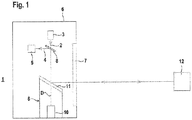
- FIG. 1 schematically shows the structure of an embodiment of the optical sensor according to the invention 1.
- the optical sensor 1 is formed in the present case as a surface distance sensor and comprises a transmitting light rays 2 emitting transmitter 3 in the form of a laser diode or the like and a receive light beams 4 receiving receiver 5 in the form of a photodiode or the like ,
- the transmitter 3 and the receiver 5 are arranged stationarily in a housing 6, in whose front wall an exit window 7 is arranged.
- a beam splitter 8 Through a beam splitter 8, a coaxial beam guidance of the transmitted light beams 2 and received light beams 4 is achieved.
- the transmitter 3 and the receiver 5 form a distance sensor, wherein the distance measurement takes place according to a pulse transit time or phase measuring method. Depending on the type of distance measurement, the transmitter 3 emits pulse-shaped or modulated with a modulation frequency transmitted light beams. 2
- the transmitted light beams 2 are deflected periodically via a deflection unit 9 in the form of a mirror 11 rotatable about a rotation axis by means of a motor 10.
- the transmitted light beams 2 are guided out of the housing 6 via the exit window 7. From an object 12, the transmitted light beams 2 are reflected back as receiving light beams 4 and passed through the exit window 7 and the beam splitter 8 to the receiver 5.
- the transmitted light beams 2 are guided in a flat detection area 13, in that object detection can be carried out by means of the optical sensor 1 ( FIG. 2 ).
- the optical sensor 1 FIG. 2
- a protective field 14 are activated.
- FIG. 3 shows a first embodiment of the electronic components of the optical sensor 1 according to FIG. 1 ,
- the optical sensor 1 in this case has an evaluation unit 15 in which received signals which are generated in the receiver 5 during object detection are evaluated. Depending on the received signals, an object detection signal is only generated when an object 12 is detected within the activated protective field 14. The object detection signal is output via an output 16.
- the optical sensor 1 is designed as a safety sensor and therefore has a fail-safe construction. This is achieved in particular by a redundant structure of the evaluation unit 15.
- the evaluation unit 15 consists of two mutually cyclically monitoring computer units.
- the output 16 is also formed fail-safe by a corresponding circuit structure. Via this output 16, a binary switching signal is output as an object detection signal, with which a system is controlled, on which a danger zone is monitored with the optical sensor 1. According to the danger zone, a protective field 14 is activated in the optical sensor 1. If, in the activated state, a particularly safety-critical object 12 is detected, a switch-off command for the system is output via the output 16 as a switching signal so that it can no longer pose a danger. If no such object 12 is detected in the protective field 14, a switching signal is output via the output 16, with which the operation of the system is enabled.
- the optical sensor 1 switching means by means of which a protective field switching can be performed.
- the switching means With the switching means Consequently, different protective fields 14 can be activated, within which the optical sensor 1 performs an object detection for generating the object detection signal, in particular of the switching signal.
- several different protective fields 14 are stored as parameterizable variables in the evaluation unit 15, it being possible to select and activate one of these protective fields 14 with the switching means, the object detection then taking place in the activated protective field 14.
- the individual protective fields 14 differ by specific protective field configurations.
- the protective field configurations can be defined by specific detectable object variables which are to be detected within the protective field 14.
- a minimum object size can be specified, so that only objects 12 whose size is greater than or equal to the minimum object size are detected during operation of the optical sensor 1 within this protective field 14.
- the protective field configuration of a protective field 14 can also be defined by specific objects 12 to be detected.
- a reflector can be specified as the object type for a protective field 14.
- object types are environmental or object contours that can be used for muting the optical sensor 1.
- protective field configurations can be defined by certain control variables. Examples include the startup behavior of the optical sensor 1 or the monitored system. In the first case, the startup behavior may be determined by the nature of the self-test of the optical sensor 1. In the second case, the startup behavior can be determined by the dead time of the system.
- the individual protective fields 14 can not only differ with regard to this protective field configuration. Rather, the protective fields 14 can also differ in terms of their dimensions.
- Essential elements of the switching means are implemented in the evaluation unit 15.
- a memory unit can be integrated in the evaluation unit 15, in which the different protective fields 14 are stored. Furthermore, with the evaluation unit 15, the activation of one of these protective fields 14 to then perform the object detection within this protective field 14.
- the switching command with which a protective field 14 is selected from the number of stored protective fields 14, can also be generated internally in the evaluation unit 15, preferably as a function of the sensor signals of the optical sensor 1.
- FIG. 3 shows a first example of this.
- an operating unit 17 is provided, such as a touch panel. Via this operating unit 17, a user can enter a switching command for selecting and activating a protective field.
- an input 18 is connected to the evaluation unit 15.
- a switching command is generated in an external unit and then read in via the input 18 into the evaluation unit 15.
- the protective field switching preferably leaves the switching signal of the optical sensor 1 unchanged, unless the switching state of the switching signal would change as a result of the change of the protective field 14.
Abstract
Die Erfindung betrifft einen optischer Sensor (1) zur Erfassung von Objekten (12) in einem Erfassungsbereich (13), mit wenigstens einem Sendelichtstrahlen (2) emittierenden Sender (3), wenigstes einem Empfangslichtstrahlen (4) empfangenden Empfänger (5) und einer Auswerteeinheit (15) zur Auswertung von im Empfänger (5) generierten Empfangssignalen. In der Auswerteeinheit (15) wird ein Objektfeststellungssignal generiert, wenn innerhalb eines aktivierten Schutzfelds (14) ein Objekt (12) erfasst wird. Weiterhin sind Umschaltmittel vorgesehen, mittels derer ein Schutzfeld (14) aus einer Anzahl von Schutzfeldern (14) mit unterschiedlichen Schutzfeldkonfigurationen aktivierbar ist, wobei unterschiedliche Schutzfeldkonfigurationen durch unterschiedliche Eigenschaften von zu detektierenden Objekten (12) und/oder von unterschiedlichen Steuerungsgrößen definiert sind.

Description
Die Erfindung betrifft einen optischen Sensor gemäß dem Oberbegriff des Anspruchs 1.The invention relates to an optical sensor according to the preamble of
Derartige optische Sensoren werden häufig auch zur Gefahrenbereichsabsicherung an Maschinen und Anlagen eingesetzt. Ein Beispiel für derartige optische Sensoren sind scannende Distanzsensoren, das heißt Flächendistanzsensoren, mittels derer das Vorfeld einer Maschine, eines Fahrzeugs oder einer Anlage überwacht wird. Diese Flächendistanzsensoren weisen ein Distanzsensorelement auf, welches Sendelichtstrahlen zur Detektion von Objekten emittiert. Zudem weist der Flächendistanzsensor eine Ablenkeinheit auf, mittels derer die Sendelichtstrahlen innerhalb einer Fläche periodisch abgelenkt werden. Mit dem Flächendistanzsensor können dann innerhalb der erfassten Fläche Objekte geortet werden, d.h. es erfolgt eine Positionsbestimmung der Objekte.Such optical sensors are often used for hazardous area protection on machines and equipment. An example of such optical sensors are scanning distance sensors, that is, area distance sensors, by means of which the apron of a machine, a vehicle or a plant is monitored. These area distance sensors have a distance sensor element which emits transmitted light beams for the detection of objects. In addition, the area distance sensor has a deflection unit, by means of which the transmitted light beams are deflected periodically within a surface. With the area distance sensor, objects can then be located within the detected area, i. there is a position determination of the objects.
Je nach Applikation, in welcher ein derartiger Flächendistanzsensor eingesetzt wird, müssen vorgegebene Bereiche an Fahrzeugen, Maschinen oder Anlagen überwacht werden. Entsprechend den Abmessungen eines solchen Bereichs wird in dem Flächendistanzsensor ein Schutzfeld vorgegebener Größe definiert, welches einen Ausschnitt der von Sendelichtstrahlen überstrichenen Fläche bildet. Dann wird mit dem Flächendistanzsensor erfasst, ob ein Objekt in das Schutzfeld eindringt. Sobald dieses der Fall ist, wird im Flächendistanzsensor ein Objektfeststellungssignal generiert, welches vorzugsweise zur Außerbetriebsetzung der überwachten Einheit führt, so dass insbesondere eine Gefährdung von einer in das Schutzfeld eindringenden Person ausgeschlossen wird.Depending on the application in which such an area distance sensor is used, predetermined areas of vehicles, machines or systems must be monitored. In accordance with the dimensions of such a region, a protective field of a predetermined size is defined in the area distance sensor, which forms a section of the area swept by transmitted light beams. Then, the area distance sensor detects whether an object penetrates into the protective field. As soon as this is the case, an object detection signal is generated in the area distance sensor, which preferably leads to the decommissioning of the monitored unit, so that in particular a hazard is excluded by a person penetrating into the protective field.
Aus der
Zur Auswahl eines Schutzfeldes sind mehrere Schalter über jeweils eine Zuleitung an einen Eingang der Auswerteeinheit angeschlossen, wobei jedem Eingang ein abgespeichertes Schutzfeld zugeordnet ist. Es ist auch Stand der Technik, dass einem Schutzfeld eine Kombination von Eingängen zugeordnet ist, d.h. unterschiedlichen Kombinationen von Eingängen können unterschiedliche Schutzfelder zugeordnet sein.For selecting a protective field, a plurality of switches are connected via a respective supply line to an input of the evaluation unit, wherein each input is assigned a stored protective field. It is also known in the art that a protective field is associated with a combination of inputs, i. Different combinations of inputs can be assigned different protective fields.
Der Erfindung liegt die Aufgabe zugrunde, die Funktionalität eines optischen Sensors der eingangs genannten Art zu erweitern.The invention has for its object to extend the functionality of an optical sensor of the type mentioned.
Zur Lösung dieser Aufgabe sind die Merkmale des Anspruchs 1 vorgesehen. Vorteilhafte Ausführungsformen und zweckmäßige Weiterbildungen der Erfindung sind in den abhängigen Ansprüchen beschrieben.To solve this problem, the features of
Die Erfindung betrifft einen optischer Sensor zur Erfassung von Objekten in einem Erfassungsbereich, mit wenigstens einem Sendelichtstrahlen emittierenden Sender, wenigstes einem Empfangslichtstrahlen empfangenden Empfänger und einer Auswerteeinheit zur Auswertung von im Empfänger generierten Empfangssignalen. In der Auswerteeinheit wird ein Objektfeststellungssignal generiert, wenn innerhalb eines aktivierten Schutzfelds ein Objekt erfasst wird. Weiterhin sind Umschaltmittel vorgesehen, mittels derer ein Schutzfeld aus einer Anzahl von Schutzfeldern mit unterschiedlichen Schutzfeldkonfigurationen aktivierbar ist, wobei unterschiedliche Schutzfeldkonfigurationen durch unterschiedliche Eigenschaften von zu detektierenden Objekten und/oder von unterschiedlichen Steuerungsgrößen definiert sind.The invention relates to an optical sensor for detecting objects in a detection area, comprising at least one transmitting light beam emissive transmitter, at least one receiving light beam receiving receiver and an evaluation unit for the evaluation of receiver signals generated in the receiver. In the evaluation unit, an object detection signal is generated when an object is detected within an activated protective field. Furthermore, switching means are provided by means of which a protective field of a number of protective fields with different protective field configurations can be activated, wherein different protective field configurations are defined by different properties of objects to be detected and / or of different control variables.
Der Grundgedanke der Erfindung besteht darin, bei dem optischen Sensor Umschaltmittel derart vorzusehen, dass mit diesen Schutzfelder mit unterschiedlichen Schutzfeldkonfigurationen ausgewählt und aktiviert werden können. Wesentlich hierbei ist, dass die einzelnen Schutzfelder mit den Schutzfeldkonfigurationen unterschiedliche Funktionalitäten aufweisen. Damit wird durch eine Aktivierung der verschiedenen Schutzfelder die Funktion des optischen Sensors geändert, wodurch eine flexible Anpassung des optischen Sensors an unterschiedliche Einsatzbereiche möglich wird.The basic idea of the invention is to provide switching means in the optical sensor in such a way that with these protective fields with different Protective field configurations can be selected and activated. It is essential that the individual protective fields have different functionalities with the protective field configurations. Thus, the activation of the various protective fields, the function of the optical sensor is changed, whereby a flexible adaptation of the optical sensor to different applications is possible.
Die unterschiedlichen Schutzfeldkonfigurationen umfassen einerseits Eigenschaften von zu detektierenden Objekten, das heißt durch eine Aktivierung von Schutzfeldern mit spezifischen Schutzfeldkonfigurationen kann das Detektionsverhalten des optischen Sensors vorgegeben werden. Die unterschiedlichen Schutzfeldkonfigurationen können weiterhin unterschiedliche Steuerungsgrößen umfassen, das heißt durch eine Auswahl von Schutzfeldern mit unterschiedlichen Schutzfeldkonfigurationen kann sowohl die interne Betriebssteuerung des optischen Sensors als auch Steuerungen externer Einheiten vorgegeben werden.On the one hand, the different protective field configurations comprise properties of objects to be detected, that is, by activating protective fields with specific protective field configurations, the detection behavior of the optical sensor can be predetermined. The different protective field configurations can furthermore comprise different control variables, that is, by selecting protective fields with different protective field configurations, both the internal operating control of the optical sensor and controls of external units can be specified.
Zusätzlich zu den Schutzfeldkonfigurationen, anhand derer sich die einzelnen Schutzfelder unterscheiden, können sich die Schutzfelder natürlich auch in ihren Abmessungen unterscheiden.In addition to the protective field configurations, on the basis of which the individual protective fields differ, the protective fields can of course also differ in their dimensions.
Weiter ist von der Erfindung auch der Fall erfasst, dass gleichzeitig mehrere Schutzfelder aktiviert sein können.Furthermore, the invention also covers the case that several protective fields can be activated at the same time.
Gemäß einer vorteilhaften Ausführungsform sind Schutzfeldkonfigurationen durch detektierbare Objektgrößen von Objekten innerhalb des Schutzfelds definiert.According to an advantageous embodiment, protective field configurations are defined by detectable object sizes of objects within the protective field.
Insbesondere können durch die Schutzfeldkonfigurationen unterschiedliche Mindestgrößen von Objekten, die innerhalb eines Schutzfelds zu erfassen sind, vorgegeben werden. Dies ist insbesondere bei einem optischen Sensor im Bereich der Sicherheitstechnik von Bedeutung. Je nach Sicherheitsanforderung müssen dort beispielsweise Mindestgrößen von Objekten, die einem Finger oder einem Bein entsprechen, erkannt werden.In particular, different minimum sizes of objects that are to be detected within a protective field can be specified by the protective field configurations. This is particularly important in the case of an optical sensor in the field of safety technology. Depending on the security requirement For example, minimum sizes of objects corresponding to a finger or a leg must be recognized there.
Gemäß einer weiteren vorteilhaften Ausgestaltung sind Schutzfeldkonfigurationen durch spezifische Objektarten von Objekten innerhalb des Schutzfelds definiert.According to a further advantageous embodiment, protective field configurations are defined by specific object types of objects within the protective field.
Insbesondere sind als spezifische Objektarten Reflektoren vorgegeben.In particular, reflectors are specified as specific object types.
Je nach Vorgabe eines Schutzfelds mit einer spezifischen Schutzfeldkonfiguration kann somit eine Erkennung eines spezifischen Objekts mit spezifischen Eigenschaften, die im Fall eines Reflektors von retroreflektierenden Eigenschaften gebildet sind, vorgegeben werden. Die Schutzfeldkonfigurationen können dahingehend verfeinert sein, dass für die Schutzfelder Schutzfeldkonfigurationen in Form bestimmter Objektklassifikationen, wie zum Beispiel unterschiedlicher Reflektorgrößen, vorgegeben werden.Depending on the specification of a protective field with a specific protective field configuration, a detection of a specific object with specific properties, which are formed in the case of a reflector of retroreflective properties, can thus be predetermined. The protective field configurations may be refined such that protective field configurations in the form of specific object classifications, such as, for example, different reflector sizes, are specified for the protective fields.
Weiter vorteilhaft sind als spezifische Objektarten Umgebungskonturen vorgegeben.Further advantageous are predetermined as specific object types environment contours.
Mit einer derartigen Konturauswertung kann ein Muting realisiert werden, das heißt eine Vorgabe von zulässigen Objekten innerhalb eines Schutzfelds, bei deren Detektion ein Objektfeststellungssignal unterdrückt wird.With such a contour evaluation, a muting can be realized, that is, a specification of permissible objects within a protective field, in the detection of which an object detection signal is suppressed.
Gemäß einer vorteilhaften Ausführungsform sind Schutzfeldkonfigurationen durch spezifische Anlaufverhalten des optischen Sensors oder einer mit dem optischen Sensor überwachten Anlage definiert.According to an advantageous embodiment, protective field configurations are defined by specific start-up behavior of the optical sensor or a system monitored by the optical sensor.
Das Anlaufverhalten bezieht sich auf die Zeit nach dem Einschalten des optischen Sensors und/oder einer mit dem optischen Sensor überwachten Anlage oder auf die Zeit nach einem Objekteingriff in das aktivierte Schutzfeld.The startup behavior refers to the time after switching on the optical sensor and / or a system monitored by the optical sensor or to the time after an object intervention in the activated protective field.
Gemäß einer ersten Variante ist das Anlaufverhalten durch einen Selbsttest des optischen Sensors definiert.According to a first variant, the startup behavior is defined by a self-test of the optical sensor.
Durch unterschiedliche Schutzfeldkonfigurationen kann beispielsweise vorgegeben werden, ob bestimmte Komponenten des optischen Sensors intern zyklisch oder innerhalb größerer Zeitintervalle geprüft werden.By means of different protective field configurations, it can be predetermined, for example, whether certain components of the optical sensor are tested internally cyclically or within larger time intervals.
Gemäß einer zweiten Variante ist das Anlaufverhalten durch die Totzeit einer Anlage definiert. Die Totzeit kann durch die Anlage selbst bedingt sein. Dabei kann die Totzeit in der Anlage hinterlegt sein. Weiterhin kann die Totzeit bei einer Anlagenkonfiguration durch einen Sicherheitstest vorgegeben sein. Alternativ kann die Totzeit durch einen eventuell notwendigen manuellen Eingriff zum Freischalten der Anlage bedingt sein.According to a second variant, the startup behavior is defined by the dead time of a plant. The dead time may be due to the plant itself. The dead time can be stored in the system. Furthermore, the dead time in a system configuration can be predetermined by a safety test. Alternatively, the dead time may be due to any manual intervention required to unlock the system.
In diesem Fall werden über die Schutzfeldkonfigurationen Parameter für externe Einheiten vorgegeben.In this case, parameters for external units are specified via the protective field configurations.
Gemäß einer besonders vorteilhaften Ausführungsform der Erfindung ist der optische Sensor ein Sicherheitssensor, welcher einen von der Auswerteeinheit angesteuerten fehlersicheren Ausgang aufweist, über welchen als Objektfeststellungssignal ein binäres Schaltsignal zur Ansteuerung einer von dem optischen Sensor überwachten Anlage ausgegeben wird.According to a particularly advantageous embodiment of the invention, the optical sensor is a safety sensor which has a fail-safe output controlled by the evaluation unit, via which a binary switching signal for controlling a system monitored by the optical sensor is output as the object detection signal.
In diesem Fall wird bei einer Detektion eines vorzugsweise sicherheitskritischen Objekts innerhalb des aktivierten Schutzfelds über den fehlersicheren Ausgang als Schaltsignal ein Abschaltbefehl für die Anlage ausgegeben. An Stelle des fehlersicheren Ausgangs als Schaltsignal kann auch eine sichere serielle Übertragung oder ein anderes sicheres Bussystem verwendet werden.In this case, when a preferably safety-critical object is detected within the activated protective field, a switch-off command for the system is output via the fail-safe output as a switching signal. Instead of the fail-safe output as a switching signal, a secure serial transmission or another secure bus system can also be used.
Besonders vorteilhaft lässt eine mit den Umschaltmitteln durchgeführte Umschaltung eines Schutzfelds das am fehlersicheren Ausgang anstehende Schaltsignal unverändert.Particularly advantageously, a changeover of a protective field performed with the switching means leaves the switching signal present at the fail-safe output unchanged.
Diese Art der Schutzfeldumschaltung führt zu einer besonders hohen Verfügbarkeit des optischen Sensors, da durch den Vorgang der Schutzfeldumschaltung das für die Objektüberwachung relevante Schaltsignal unverändert gültig bleibt, das heißt es entsteht keine zeitliche Lücke bei der Überwachung mit dem optischen Sensor.This type of protective field switching leads to a particularly high availability of the optical sensor, since the operation of the protective field switching, the relevant for the object monitoring switching signal remains valid, that is, there is no time gap in the monitoring with the optical sensor.
Eine Ausnahme besteht natürlich dann, wenn durch eine Schutzfeldumschaltung ein Eingriff eines Objekts in das aktivierte Schutzfeld auftritt. In diesem Fall ändert sich natürlich das Schaltsignal.An exception, of course, is when an intervention of an object in the activated protective field occurs due to a protective field changeover. In this case, of course, the switching signal changes.
Besonders zweckmäßig weist der optische Sensor eine Speichereinheit auf, in welcher eine Anzahl von Schutzfeldern mit unterschiedlichen Schutzfeldkonfigurationen gespeichert ist. Zur Aktivierung eines Schutzfelds wird mittels der Umschaltmittel eines der gespeicherten Schutzfelder ausgewählt.The optical sensor particularly expediently has a memory unit in which a number of protective fields with different protective field configurations are stored. To activate a protective field, one of the stored protective fields is selected by means of the switching means.
Dabei kann insbesondere die Speichereinheit in der Auswerteeinheit integriert sein. Die Anzahl der gespeicherten Schutzfelder gibt in diesem Fall die Umschaltmöglichkeiten vor, die mit den Umschaltmitteln durchgeführt werden. Die Anzahl der gespeicherten Schutzfelder und Schutzfeldkonfigurationen kann zweckmäßig durch einen Parametriervorgang vorgegeben und bei Bedarf geändert werden.In this case, in particular, the memory unit can be integrated in the evaluation unit. The number of stored protective fields in this case specifies the switching options that are carried out with the switching means. The number of stored protective fields and protective field configurations can be suitably specified by a parameterization process and changed if necessary.
Gemäß einer ersten Variante weisen die Umschaltmittel wenigstens einen Eingang auf, über welchen von einer externen Einheit ein Umschaltbefehl generiert wird. Darunter fällt auch die Möglichkeit, unterschiedlichen Eingangskombinationen unterschiedliche Schutzfelder zuzuordnen.According to a first variant, the switching means have at least one input via which a switching command is generated by an external unit. This also includes the possibility of assigning different protective fields to different input combinations.
Beispielsweise kann die externe Einheit von einer Steuereinheit gebildet sein. Bei einer Applikation, bei welcher der optische Sensor auf einem Fahrzeug wie einem fahrerlosen Transportsystem angeordnet ist, kann die Steuereinheit von der Fahrzeugsteuerung gebildet sein, die abhängig vom aktuellen Fahrzustand durch Vergabe von Umschaltbefehlen geeignete Schutzfeldkonfigurationen auswählt.For example, the external unit may be formed by a control unit. In an application in which the optical sensor is arranged on a vehicle such as a driverless transport system, the control unit may be formed by the vehicle control, which depends on the current driving state assign suitable protective field configurations by assigning switching commands.
Gemäß einer zweiten Variante wird in den Umschaltmitteln abhängig von mit dem optischen Sensor generierten Sensorsignalen ein Umschaltbefehl generiert.According to a second variant, a switching command is generated in the switching means as a function of sensor signals generated with the optical sensor.
In diesem Fall generiert der optische Sensor selbst Umschaltbefehle. Ist der optische Sensor beispielsweise auf einem Fahrzeug wie einem fahrerlosen Transportsystem angeordnet, so kann anhand von mit dem optischen Sensor generierten Sensorsignalen die Geschwindigkeit und/oder Fahrtrichtung des Fahrzeugs bestimmt werden, wobei in Abhängigkeit dieser Parameter mittels der Umschaltmittel eine selbsttätige Schutzfeldumschaltung erfolgen kann.In this case, the optical sensor itself generates switching commands. If the optical sensor is arranged, for example, on a vehicle such as a driverless transport system, then the speed and / or direction of travel of the vehicle can be determined on the basis of sensor signals generated by the optical sensor, wherein an automatic protective field switching can take place as a function of these parameters by means of the switching means.
Gemäß einer dritten Variante weisen die Umschaltmittel eine Bedienereinheit für eine benutzergeführte Schutzfeldumschaltung auf.According to a third variant, the switching means have an operator unit for user-guided protective field switching.
Die Bedieneinheit kann von einem Bedienfeld wie einem Touchpanel gebildet sein. In diesem Fall kann ein Benutzer selbst Umschaltbefehle zur Schutzfeldumschaltung generieren.The operating unit can be formed by a control panel such as a touch panel. In this case, a user can generate self-switching commands for protective field switching.
Der optische Sensor kann gemäß einer ersten Variante ein scannender Distanzsensor sein.The optical sensor may be a scanning distance sensor according to a first variant.
Dabei kann der optische Sensor einen Flächendistanzsensor bilden, bei dem der Sender und der Empfänger einen Distanzsensor bilden und stationär in einem Gehäuse des optischen Sensors angeordnet sind. Dem Distanzsensor ist eine Ablenkeinheit, beispielsweise in Form eines rotierenden Spiegels zugeordnet, über welche die Sendelichtstrahlen geführt und so periodisch innerhalb eines flächigen Erfassungsbereichs geführt sind.In this case, the optical sensor can form a surface distance sensor, in which the transmitter and the receiver form a distance sensor and are arranged stationarily in a housing of the optical sensor. The distance sensor is associated with a deflection unit, for example in the form of a rotating mirror, via which the transmitted light beams are guided and thus guided periodically within a two-dimensional detection area.
Alternativ kann der scannende Distanzsensor so ausgebildet sein, dass der Sender und Empfänger, welche den Distanzsensor bilden, in einem rotierenden Messkopf angeordnet sind.Alternatively, the scanning distance sensor may be configured so that the transmitter and receiver, which form the distance sensor, are arranged in a rotating measuring head.
Gemäß einer zweiten Variante ist der optische Sensor ein Kamera-Sensor.According to a second variant, the optical sensor is a camera sensor.
In diesem Fall ist der Empfänger von wenigstens einem Bildsensor gebildet, vorzugsweise einem zeilenförmigen oder matrixförmigen CCD- oder CMOS-Array. Als Sender sind ein oder mehrere Leuchtdioden oder Laserdioden vorgesehen. Ein derartiger Kamerasensor kann auch als Distanzmesssystem ausgebildet sein, indem für die einzelnen lichtempfindlichen Elemente beispielsweise nach einem Laufzeitverfahren die Distanz zu einem zu detektierenden Objekt bestimmt wird.In this case, the receiver is formed by at least one image sensor, preferably a line-shaped or matrix-shaped CCD or CMOS array. As a transmitter, one or more light-emitting diodes or laser diodes are provided. Such a camera sensor can also be designed as a distance measuring system in that, for example, the distance to an object to be detected is determined for the individual photosensitive elements according to a transit time method.
Gemäß einer dritten Variante ist der optische Sensor ein nach dem Lichttasterprinzip arbeitender Lichtvorhang.According to a third variant of the optical sensor is a working according to the light sensor principle light curtain.
In diesem Fall besteht der optische Sensor aus einer Mehrfachanordnung von Lichttastern mit jeweils einem Sender und einem Empfänger. Die Sender und Empfänger können in einem gemeinsamen Gehäuse oder auch in separaten Gehäusen untergebracht sein.In this case, the optical sensor consists of a multiple array of light probes, each with a transmitter and a receiver. The transmitter and receiver can be housed in a common housing or in separate housings.
Die Erfindung wird im Folgenden anhand der Zeichnungen erläutert. Es zeigen:
- Figur 1:
- Schematische Darstellung der optischen Komponenten eines als Flächendistanzsensor ausgebildeten optischen Sensors.
- Figur 2:
- Schematische Darstellung des mit dem optischen Sensor erfassten Erfassungsbereichs und eines im Erfassungsbereich angeordneten Schutzfelds.
- Figur 3:
- Erste Ausführungsform der elektronischen Komponenten des optischen Sensors gemäß
Figur 1 - Figur 4:
- Zweite Ausführungsform der elektronischen Komponenten des optischen Sensors gemäß
Figur 1
- FIG. 1:
- Schematic representation of the optical components of an optical sensor designed as a surface distance sensor.
- FIG. 2:
- Schematic representation of the detection range detected by the optical sensor and a protective field arranged in the detection area.
- FIG. 3:
- First embodiment of the electronic components of the optical sensor according to
FIG. 1 , - FIG. 4:
- Second embodiment of the electronic components of the optical sensor according to
FIG. 1 ,
Die Sendelichtstrahlen 2 werden über eine Ablenkeinheit 9 in Form eines mittels eines Motors 10 um eine Drehachse drehbaren Spiegels 11 periodisch abgelenkt. Die Sendelichtstrahlen 2 werden über das Austrittsfenster 7 aus dem Gehäuse 6 geführt. Von einem Objekt 12 werden die Sendelichtstrahlen 2 als Empfangslichtstrahlen 4 zurückreflektiert und über das Austrittsfenster 7 und den Strahlteiler 8 zum Empfänger 5 geführt.The transmitted light beams 2 are deflected periodically via a deflection unit 9 in the form of a
Durch die Ablenkbewegung der Ablenkeinheit 9 werden die Sendelichtstrahlen 2 in einem flächigen Erfassungsbereich 13 geführt, indem mittels des optischen Sensors 1 eine Objektdetektion erfolgen kann (
Im vorliegenden Fall ist der optische Sensor 1 als Sicherheitssensor ausgebildet und weist demzufolge einen fehlersicheren Aufbau auf. Dies wird insbesondere durch einen redundanten Aufbau der Auswerteeinheit 15 erreicht. Vorzugsweise besteht die Auswerteeinheit 15 aus zwei sich gegeneinander zyklisch überwachenden Rechnereinheiten.In the present case, the
Der Ausgang 16 ist durch einen entsprechenden Schaltungsaufbau ebenfalls fehlersicher ausgebildet. Über diesen Ausgang 16 wird als Objektfeststellungssignal ein binäres Schaltsignal ausgegeben, mit dem eine Anlage gesteuert wird, an welcher ein Gefahrenbereich mit dem optischen Sensor 1 überwacht wird. Entsprechend des Gefahrenbereichs ist im optischen Sensor 1 ein Schutzfeld 14 aktiviert. Wird im aktivierten Zustand ein insbesondere sicherheitskritisches Objekt 12 erfasst, wird über den Ausgang 16 als Schaltsignal ein Abschaltbefehl für die Anlage ausgegeben, so dass von dieser keine Gefahr mehr ausgehen kann. Wird kein solches Objekt 12 im Schutzfeld 14 erkannt, wird über den Ausgang 16 ein Schaltsignal ausgegeben, mit dem der Betrieb der Anlage freigegeben ist.The
Erfindungsgemäß weist der optische Sensor 1 Umschaltmittel auf, mittels derer eine Schutzfeldumschaltung durchgeführt werden kann. Mit den Umschaltmitteln können demzufolge unterschiedliche Schutzfelder 14 aktiviert werden, innerhalb derer der optische Sensor 1 eine Objektdetektion zur Generierung des Objektfeststellungssignals, insbesondere des Schaltsignals durchführt.According to the invention, the
Vorteilhaft sind als parametrierbare Größen in der Auswerteeinheit 15 mehrere unterschiedliche Schutzfelder 14 abgespeichert, wobei mit den Umschaltmitteln eines dieser Schutzfelder 14 ausgewählt und aktiviert werden kann, wobei im aktivierten Schutzfeld 14 dann die Objektdetektion erfolgt.Advantageously, several different
Die einzelnen Schutzfelder 14 unterscheiden sich durch spezifische Schutzfeldkonfigurationen. Die Schutzfeldkonfigurationen können einerseits durch bestimmte detektierbare Objektgrößen, die innerhalb des Schutzfelds 14 zu erfassen sind, definiert sein. Beispielsweise kann als Schutzfeldkonfiguration für ein Schutzfeld 14 eine minimale Objektgröße vorgegeben werden, so dass dann im Betrieb des optischen Sensors 1 innerhalb dieses Schutzfelds 14 nur Objekte 12 erkannt werden, deren Größe größer oder gleich der minimalen Objektgröße ist.The individual
Die Schutzfeldkonfiguration eines Schutzfelds 14 kann auch durch spezifische zu erfassende Objekte 12 definiert sein. Beispielsweise kann als Objektart für ein Schutzfeld 14 ein Reflektor vorgegeben sein. Weitere Beispiele für Objektarten sind Umgebungs- oder Objektkonturen, die für ein Muting des optischen Sensors 1 genutzt werden können.The protective field configuration of a
Schließlich können Schutzfeldkonfigurationen durch bestimmte Steuerungsgrößen definiert sein. Beispiele hierfür sind das Anlaufverhalten des optischen Sensors 1 oder der überwachten Anlage. Im ersten Fall kann das Anlaufverhalten durch die Art des Selbsttests des optischen Sensors 1 bestimmt sein. Im zweiten Fall kann das Anlaufverhalten durch die Totzeit der Anlage bestimmt sein.Finally, protective field configurations can be defined by certain control variables. Examples include the startup behavior of the
Die einzelnen Schutzfelder 14 können sich nicht nur hinsichtlich dieser Schutzfeldkonfiguration unterscheiden. Vielmehr können sich die Schutzfelder 14 auch hinsichtlich ihrer Abmessungen unterscheiden.The individual
Wesentliche Elemente der Umschaltmittel sind in der Auswerteeinheit 15 implementiert. So kann in der Auswerteeinheit 15 eine Speichereinheit integriert sein, in der die unterschiedlichen Schutzfelder 14 abgespeichert sind. Weiterhin erfolgt mit der Auswerteeinheit 15 die Aktivierung eines dieser Schutzfelder 14, um dann innerhalb dieses Schutzfelds 14 die Objektdetektion durchzuführen.Essential elements of the switching means are implemented in the
Schließlich kann auch der Umschaltbefehl, mit dem ein Schutzfeld 14 aus der Anzahl der gespeicherten Schutzfelder 14 ausgewählt wird, intern in der Auswerteeinheit 15, vorzugsweise abhängig von den Sensorsignalen des optischen Sensors 1 generiert werden.Finally, the switching command, with which a
Alternativ wird ein extern generierter Umschaltbefehl zur Auswahl eines Schutzfelds 14 verwendet.
Bei der Anordnung gemäß
Die Schutzfeldumschaltung lässt vorzugsweise das Schaltsignal des optischen Sensors 1 unverändert, es sei denn, dass sich durch den Wechsel des Schutzfelds 14 der Schaltzustand des Schaltsignals ändern würde.The protective field switching preferably leaves the switching signal of the
- (1)(1)
- Optischer SensorOptical sensor
- (2)(2)
- SendelichtstrahlenTransmitted light beams
- (3)(3)
- Sendertransmitter
- (4)(4)
- EmpfangslichtstrahlenReceiving light rays
- (5)(5)
- Empfängerreceiver
- (6)(6)
- Gehäusecasing
- (7)(7)
- Austrittsfensterexit window
- (8)(8th)
- Strahlteilerbeamsplitter
- (9)(9)
- AblenkeinheitDeflector
- (10)(10)
- Motorengine
- (11)(11)
- Spiegelmirror
- (12)(12)
- Objektobject
- (13)(13)
- Erfassungsbereichdetection range
- (14)(14)
- Schutzfeldprotection field
- (15)(15)
- Auswerteeinheitevaluation
- (16)(16)
- Ausgangoutput
- (17)(17)
- Bedienereinheitoperator unit
- (18)(18)
- Eingangentrance
Claims (20)
Priority Applications (1)
| Application Number | Priority Date | Filing Date | Title |
|---|---|---|---|
| EP16159085.6A EP3217195B1 (en) | 2016-03-08 | 2016-03-08 | Optical sensor |
Applications Claiming Priority (1)
| Application Number | Priority Date | Filing Date | Title |
|---|---|---|---|
| EP16159085.6A EP3217195B1 (en) | 2016-03-08 | 2016-03-08 | Optical sensor |
Publications (2)
| Publication Number | Publication Date |
|---|---|
| EP3217195A1 true EP3217195A1 (en) | 2017-09-13 |
| EP3217195B1 EP3217195B1 (en) | 2023-04-26 |
Family
ID=55527804
Family Applications (1)
| Application Number | Title | Priority Date | Filing Date |
|---|---|---|---|
| EP16159085.6A Active EP3217195B1 (en) | 2016-03-08 | 2016-03-08 | Optical sensor |
Country Status (1)
| Country | Link |
|---|---|
| EP (1) | EP3217195B1 (en) |
Cited By (5)
| Publication number | Priority date | Publication date | Assignee | Title |
|---|---|---|---|---|
| CN109140579A (en) * | 2018-07-25 | 2019-01-04 | 浙江工业大学 | The rotary heating device and method for collecting ranging, surveying mild heat one |
| EP3578319A1 (en) * | 2018-06-07 | 2019-12-11 | Sick AG | Method for securing a hazardous area |
| CN110895335A (en) * | 2018-09-12 | 2020-03-20 | 西克股份公司 | Sensor and autonomous vehicle |
| EP3770635A1 (en) * | 2019-07-25 | 2021-01-27 | Leuze electronic GmbH + Co. KG | Safety sensor with variable clock rate and / or interim aktivation of components |
| EP3851729A1 (en) * | 2020-01-16 | 2021-07-21 | Leuze electronic GmbH + Co. KG | Optical sensor and method for detecting objects using an optical sensor |
Citations (7)
| Publication number | Priority date | Publication date | Assignee | Title |
|---|---|---|---|---|
| DE3912398A1 (en) * | 1989-04-15 | 1990-10-18 | Bayerische Motoren Werke Ag | OBJECT DETECTING DEVICE FOR MOTOR VEHICLES |
| DE19917509C1 (en) | 1999-04-17 | 2000-05-25 | Leuze Electronic Gmbh & Co | Optoelectronic device for detecting objects in a monitored area; has dimensions of monitored areas stored in evaluation unit for activation by one of several switches connected to inputs |
| EP1331433A2 (en) * | 2002-01-25 | 2003-07-30 | Keyence Corporation | Multi-optical-path photoelectric safety apparatus |
| EP1443343A2 (en) * | 2003-02-01 | 2004-08-04 | Leuze lumiflex GmbH + Co. KG | Optical sensor with a plurality of switching outputs |
| DE102006012537A1 (en) * | 2006-03-18 | 2007-09-20 | Leuze Lumiflex Gmbh + Co. Kg | light Curtain |
| US20100097665A1 (en) * | 2008-10-22 | 2010-04-22 | Omron Scientific Technologies, Inc. | Apparatus and Method for Pattern-Based Configuration of Optical Sensing Systems |
| US20120123563A1 (en) * | 2010-11-17 | 2012-05-17 | Omron Scientific Technologies, Inc. | Method and Apparatus for Monitoring Zones |
-
2016
- 2016-03-08 EP EP16159085.6A patent/EP3217195B1/en active Active
Patent Citations (7)
| Publication number | Priority date | Publication date | Assignee | Title |
|---|---|---|---|---|
| DE3912398A1 (en) * | 1989-04-15 | 1990-10-18 | Bayerische Motoren Werke Ag | OBJECT DETECTING DEVICE FOR MOTOR VEHICLES |
| DE19917509C1 (en) | 1999-04-17 | 2000-05-25 | Leuze Electronic Gmbh & Co | Optoelectronic device for detecting objects in a monitored area; has dimensions of monitored areas stored in evaluation unit for activation by one of several switches connected to inputs |
| EP1331433A2 (en) * | 2002-01-25 | 2003-07-30 | Keyence Corporation | Multi-optical-path photoelectric safety apparatus |
| EP1443343A2 (en) * | 2003-02-01 | 2004-08-04 | Leuze lumiflex GmbH + Co. KG | Optical sensor with a plurality of switching outputs |
| DE102006012537A1 (en) * | 2006-03-18 | 2007-09-20 | Leuze Lumiflex Gmbh + Co. Kg | light Curtain |
| US20100097665A1 (en) * | 2008-10-22 | 2010-04-22 | Omron Scientific Technologies, Inc. | Apparatus and Method for Pattern-Based Configuration of Optical Sensing Systems |
| US20120123563A1 (en) * | 2010-11-17 | 2012-05-17 | Omron Scientific Technologies, Inc. | Method and Apparatus for Monitoring Zones |
Cited By (9)
| Publication number | Priority date | Publication date | Assignee | Title |
|---|---|---|---|---|
| EP3578319A1 (en) * | 2018-06-07 | 2019-12-11 | Sick AG | Method for securing a hazardous area |
| US10726538B2 (en) | 2018-06-07 | 2020-07-28 | Sick Ag | Method of securing a hazard zone |
| CN109140579A (en) * | 2018-07-25 | 2019-01-04 | 浙江工业大学 | The rotary heating device and method for collecting ranging, surveying mild heat one |
| CN109140579B (en) * | 2018-07-25 | 2021-05-04 | 浙江工业大学 | Rotary heating device and method integrating ranging, temperature measuring and heating |
| CN110895335A (en) * | 2018-09-12 | 2020-03-20 | 西克股份公司 | Sensor and autonomous vehicle |
| EP3623845B1 (en) * | 2018-09-12 | 2022-06-22 | Sick Ag | Sensor and autonomous vehicle |
| US11442167B2 (en) | 2018-09-12 | 2022-09-13 | Sick Ag | Sensor and autonomous vehicle |
| EP3770635A1 (en) * | 2019-07-25 | 2021-01-27 | Leuze electronic GmbH + Co. KG | Safety sensor with variable clock rate and / or interim aktivation of components |
| EP3851729A1 (en) * | 2020-01-16 | 2021-07-21 | Leuze electronic GmbH + Co. KG | Optical sensor and method for detecting objects using an optical sensor |
Also Published As
| Publication number | Publication date |
|---|---|
| EP3217195B1 (en) | 2023-04-26 |
Similar Documents
| Publication | Publication Date | Title |
|---|---|---|
| EP3217195A1 (en) | Optical sensor | |
| DE19917509C1 (en) | Optoelectronic device for detecting objects in a monitored area; has dimensions of monitored areas stored in evaluation unit for activation by one of several switches connected to inputs | |
| EP2053538B1 (en) | Securing a surveillance area and visual support for automatic processing | |
| EP1816487B1 (en) | Light barrier | |
| DE102008032216A1 (en) | Device for detecting the presence of an object in space | |
| DE10312972B3 (en) | Optical sensor for detecting objects within surveillance zone with selection of different protected fields within latter by activation signals received via bidirectional data communications interface | |
| EP3220164B1 (en) | Method for operating a distance measuring monitoring sensor and monitoring sensor | |
| EP3640522B1 (en) | Monitoring device | |
| EP3401702A1 (en) | Sensor system | |
| EP3587894A1 (en) | Sensor assembly and method for operating a sensor assembly | |
| EP3640521B1 (en) | Monitoring device | |
| DE202015106835U1 (en) | sensor | |
| EP2527868A1 (en) | Optoelectronic security sensor to measure distance for monitoring a surveillance area | |
| EP3882505B1 (en) | Monitoring device and method for operating same | |
| DE202020103157U1 (en) | Monitoring device | |
| EP1895329A2 (en) | Device for recording objects in a surveillance range | |
| EP3540380B1 (en) | Monitoring arrangement for a plant | |
| DE102017103791B4 (en) | Optoelectronic sensor and method for detecting objects | |
| DE10155583B4 (en) | circuitry | |
| DE102017004030B4 (en) | Method and device for securing a work space | |
| EP4119982B1 (en) | Monitoring device and method for operating same | |
| EP3663797A1 (en) | Monitoring device | |
| EP3862617B1 (en) | Device for securing a hazardous area | |
| DE202022103538U1 (en) | monitoring device | |
| EP3629066B1 (en) | Optical sensor |
Legal Events
| Date | Code | Title | Description |
|---|---|---|---|
| PUAI | Public reference made under article 153(3) epc to a published international application that has entered the european phase |
Free format text: ORIGINAL CODE: 0009012 |
|
| STAA | Information on the status of an ep patent application or granted ep patent |
Free format text: STATUS: REQUEST FOR EXAMINATION WAS MADE |
|
| 17P | Request for examination filed |
Effective date: 20170119 |
|
| AK | Designated contracting states |
Kind code of ref document: A1 Designated state(s): AL AT BE BG CH CY CZ DE DK EE ES FI FR GB GR HR HU IE IS IT LI LT LU LV MC MK MT NL NO PL PT RO RS SE SI SK SM TR |
|
| AX | Request for extension of the european patent |
Extension state: BA ME |
|
| STAA | Information on the status of an ep patent application or granted ep patent |
Free format text: STATUS: EXAMINATION IS IN PROGRESS |
|
| 17Q | First examination report despatched |
Effective date: 20210426 |
|
| STAA | Information on the status of an ep patent application or granted ep patent |
Free format text: STATUS: EXAMINATION IS IN PROGRESS |
|
| GRAP | Despatch of communication of intention to grant a patent |
Free format text: ORIGINAL CODE: EPIDOSNIGR1 |
|
| STAA | Information on the status of an ep patent application or granted ep patent |
Free format text: STATUS: GRANT OF PATENT IS INTENDED |
|
| INTG | Intention to grant announced |
Effective date: 20230207 |
|
| GRAS | Grant fee paid |
Free format text: ORIGINAL CODE: EPIDOSNIGR3 |
|
| GRAA | (expected) grant |
Free format text: ORIGINAL CODE: 0009210 |
|
| STAA | Information on the status of an ep patent application or granted ep patent |
Free format text: STATUS: THE PATENT HAS BEEN GRANTED |
|
| RBV | Designated contracting states (corrected) |
Designated state(s): DE |
|
| AK | Designated contracting states |
Kind code of ref document: B1 Designated state(s): DE |
|
| REG | Reference to a national code |
Ref country code: DE Ref legal event code: R096 Ref document number: 502016015714 Country of ref document: DE |
|
| REG | Reference to a national code |
Ref country code: DE Ref legal event code: R097 Ref document number: 502016015714 Country of ref document: DE |
|
| PLBE | No opposition filed within time limit |
Free format text: ORIGINAL CODE: 0009261 |
|
| STAA | Information on the status of an ep patent application or granted ep patent |
Free format text: STATUS: NO OPPOSITION FILED WITHIN TIME LIMIT |
|
| 26N | No opposition filed |
Effective date: 20240129 |