EP3219280A1 - Pre-formed curved ablation catheter - Google Patents
Pre-formed curved ablation catheter Download PDFInfo
- Publication number
- EP3219280A1 EP3219280A1 EP17162351.5A EP17162351A EP3219280A1 EP 3219280 A1 EP3219280 A1 EP 3219280A1 EP 17162351 A EP17162351 A EP 17162351A EP 3219280 A1 EP3219280 A1 EP 3219280A1
- Authority
- EP
- European Patent Office
- Prior art keywords
- distal end
- catheter
- sheath
- longitudinal axis
- cavity
- Prior art date
- Legal status (The legal status is an assumption and is not a legal conclusion. Google has not performed a legal analysis and makes no representation as to the accuracy of the status listed.)
- Granted
Links
Images

Classifications
-
- A—HUMAN NECESSITIES
- A61—MEDICAL OR VETERINARY SCIENCE; HYGIENE
- A61B—DIAGNOSIS; SURGERY; IDENTIFICATION
- A61B18/00—Surgical instruments, devices or methods for transferring non-mechanical forms of energy to or from the body
- A61B18/18—Surgical instruments, devices or methods for transferring non-mechanical forms of energy to or from the body by applying electromagnetic radiation, e.g. microwaves
-
- A—HUMAN NECESSITIES
- A61—MEDICAL OR VETERINARY SCIENCE; HYGIENE
- A61B—DIAGNOSIS; SURGERY; IDENTIFICATION
- A61B18/00—Surgical instruments, devices or methods for transferring non-mechanical forms of energy to or from the body
- A61B18/04—Surgical instruments, devices or methods for transferring non-mechanical forms of energy to or from the body by heating
- A61B18/12—Surgical instruments, devices or methods for transferring non-mechanical forms of energy to or from the body by heating by passing a current through the tissue to be heated, e.g. high-frequency current
- A61B18/14—Probes or electrodes therefor
- A61B18/1492—Probes or electrodes therefor having a flexible, catheter-like structure, e.g. for heart ablation
-
- A—HUMAN NECESSITIES
- A61—MEDICAL OR VETERINARY SCIENCE; HYGIENE
- A61B—DIAGNOSIS; SURGERY; IDENTIFICATION
- A61B17/00—Surgical instruments, devices or methods, e.g. tourniquets
- A61B2017/00831—Material properties
- A61B2017/00867—Material properties shape memory effect
-
- A—HUMAN NECESSITIES
- A61—MEDICAL OR VETERINARY SCIENCE; HYGIENE
- A61B—DIAGNOSIS; SURGERY; IDENTIFICATION
- A61B34/00—Computer-aided surgery; Manipulators or robots specially adapted for use in surgery
- A61B34/20—Surgical navigation systems; Devices for tracking or guiding surgical instruments, e.g. for frameless stereotaxis
- A61B2034/2046—Tracking techniques
- A61B2034/2051—Electromagnetic tracking systems
-
- A—HUMAN NECESSITIES
- A61—MEDICAL OR VETERINARY SCIENCE; HYGIENE
- A61B—DIAGNOSIS; SURGERY; IDENTIFICATION
- A61B90/00—Instruments, implements or accessories specially adapted for surgery or diagnosis and not covered by any of the groups A61B1/00 - A61B50/00, e.g. for luxation treatment or for protecting wound edges
- A61B90/06—Measuring instruments not otherwise provided for
- A61B2090/067—Measuring instruments not otherwise provided for for measuring angles
-
- C—CHEMISTRY; METALLURGY
- C08—ORGANIC MACROMOLECULAR COMPOUNDS; THEIR PREPARATION OR CHEMICAL WORKING-UP; COMPOSITIONS BASED THEREON
- C08L—COMPOSITIONS OF MACROMOLECULAR COMPOUNDS
- C08L2201/00—Properties
- C08L2201/12—Shape memory
Definitions
- the present invention relates generally to methods and devices for invasive medical treatment, and specifically to catheters.
- RF ablation for example, a catheter is inserted into the heart and brought into contact with tissue at a target location. RF energy is then applied through an electrode on the catheter in order to create a lesion for the purpose of breaking arrhythmogenic current paths in the tissue.
- RF radio-frequency
- U.S. Patent 6,064,902 describes a catheter for ablating tissue on the inner wall of a blood vessel, such as a pulmonary vein.
- the tip portion of the catheter is deflectable from a first, generally straight, configuration, in which the proximal and distal sections are substantially co-linear, to a second, J-shaped, configuration in which the proximal and distal sections are generally parallel with a separation therebetween substantially corresponding to the inside diameter of the blood vessel.
- the distal end portion of the catheter is rotated about the longitudinal axis of the catheter to cause a circumferential displacement of proximal and distal ablation electrodes on the catheter along the inner wall of the pulmonary vein.
- the electrode catheter may be used to ablate a number of circumferentially-spaced sites on the inner wall of the pulmonary vein by ablating one or two sites at each circumferential position.
- Embodiments of the present invention that are described hereinbelow provide invasive devices and methods for contacting tissue within the body with enhanced safety and efficacy.
- a medical device including an insertion tube, having a longitudinal axis and having a distal end adapted for insertion through a body passage into a cavity within a body of a patient.
- An electrode is located on the distal end of the insertion tube and is configured to contact tissue in the cavity.
- a resilient member which may include a shape memory material, is contained within the distal end of the insertion tube and is configured, when unconstrained, to cause the distal end to bend away from the longitudinal axis in a curved shape and to straighten toward the longitudinal axis when subjected to a force.
- the device includes at least one position transducer in the distal end of the insertion tube.
- the at least one position transducer may be configured to measure a bend angle of the distal end of the insertion tube.
- the at least one position transducer typically includes two position transducers at different longitudinal locations within the distal end of the insertion tube.
- the resilient member is configured to straighten toward the longitudinal axis when the force is applied in an inward radial force.
- the resilient member may be configured to buckle when the radial force exceeds a predetermined threshold.
- medical apparatus including a sheath, which has a longitudinal axis and a distal opening and is adapted for insertion through a body passage into a cavity within a body of a patient.
- a catheter is configured for insertion through the sheath into the cavity and has a resilient distal end that is formed so that, when unconstrained, the distal end bends away from the longitudinal axis in a curved shape, and when subjected to a force, the distal end straightens toward the longitudinal axis.
- the sheath exerts the force in an inward radial direction so as to straighten the distal end of the catheter during passage of the distal end through the sheath, and the distal end of the catheter assumes the curved shape after passing through the distal opening of the sheath into the cavity.
- the catheter is configured to rotate about the axis within the sheath.
- the catheter includes an electrode at the distal end, which is configured to contact tissue in the cavity.
- the apparatus may include a radio frequency (RF) generator, which is coupled to supply RF energy through the catheter to the electrode so as to ablate the tissue.
- RF radio frequency
- the catheter includes a position transducer in the distal end
- the apparatus includes a position sensing system, which is configured to communicate with the position transducer so as to determine a location of the distal end within the body.
- the position sensing system may be configured to provide an indication of a bend angle of the distal end of the catheter.
- a method for medical treatment including inserting a sheath, having a longitudinal axis and a distal opening, through a body passage into a cavity within a body of a patient.
- a catheter is inserted into the sheath, wherein the catheter has a resilient distal end that is formed so that, when unconstrained, the distal end bends away from the longitudinal axis in a curved shape, and when subjected to a force, the distal end straightens toward the longitudinal axis.
- the catheter is advanced through the sheath so that the distal end of the catheter passes through the distal opening of the sheath into the cavity and assumes the curved shape.
- the catheter is manipulated within the cavity so that the distal end contacts tissue in the cavity, and the catheter is moved within the sheath while the distal end contacts the tissue so as to cause the distal end to trace a desired path along the tissue.
- moving the catheter includes rotating the catheter about the axis.
- the cavity includes a blood vessel, and rotating the catheter causes the distal end to trace a circular path around an internal circumference of the blood vessel.
- inserting the sheath may include passing the sheath percutaneously through a vascular system of the patient into a left atrium of a heart of the patient, and advancing the catheter may include positioning the distal end of the catheter in a pulmonary vein so as to trace the circular path within an ostium of the pulmonary vein.
- the method includes providing an indication of a bending angle of the distal end of the catheter, and controlling a pressure of the distal end against the tissue responsively to the indication.
- Embodiments of the present invention that are described hereinbelow provide simple, safe, and reliable devices and methods for ablating tissue along a selected path inside a body cavity. Some of these embodiments are particularly suitable for ablating circumferential paths inside a tubular structure, such as a blood vessel. The principles of the present invention may also be applied, however, on linear paths and in applications other than ablation.
- a medical device such as a catheter, comprises an insertion tube, which is inserted through a body passage into a body cavity, such as a chamber of the heart.
- the insertion tube has an electrode at its distal tip, which makes contact with tissue in the cavity.
- the distal end of the insertion tube contains a resilient member, such as a shape memory strut, which is pre-formed so as to cause the distal end to bend away from the longitudinal axis of the insertion tube in a curved shape as long as the catheter is not constrained by a radial force.
- a resilient member such as a shape memory strut
- the distal tip of the catheter When a force is applied against the distal tip of the catheter in the appropriate direction, such as an inward radial force, it causes the distal end to straighten toward the longitudinal axis.
- the bend angle thus gives an indication of the force with which the catheter tip is pressing against the tissue.
- the distal tip of the catheter may be made structurally weak enough to buckle if the pressure against the tissue is greater than a certain threshold, thus giving an extra measure of safety against excessive pressure that might otherwise puncture the tissue
- This pre-formed curved catheter may be used to ablate tissue along circumferential paths inside the pulmonary veins.
- a sheath is inserted into the left atrium, typically via the fossa ovalis, and is positioned coaxially with the pulmonary vein in which the ablation is to be performed.
- the catheter is passed through the sheath (which radially constrains the catheter to remain straight while passing through the sheath) until the distal end of the catheter projects out of the sheath and into the vein.
- the curved shape of the distal end projecting out of the sheath causes the electrode at the distal tip of the catheter to contact the inner wall of the vein.
- the angle and length of the curved end of the catheter are chosen so that the distal tip presses against the inner wall of the vein when the longitudinal axis of the sheath and the catheter insertion tube is aligned with the axis of the vein.
- an operator manipulates the catheter so that the electrode contacts the tissue in the ostium of the vein, and then rotates the shaft of the catheter in the sheath while applying RF energy to the electrode.
- This rotation causes the electrode to move around the inner circumference of the vein in a circular path and to ablate the tissue along the path as it goes.
- the RF energy may be actuated intermittently to ablate selected points along the path.
- the physician may apply other movements in order to trace different sorts of paths with the catheter.
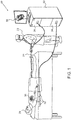
- Fig. 1 is a schematic pictorial illustration of a system 20 for ablation of tissue in a heart 26 of a patient 28, in accordance with an embodiment of the present invention.
- An operator 22 such as a cardiologist, inserts a catheter 24 through the vascular system of patient 28 so that the distal end of the catheter enters a chamber of the patient's heart. Operator 22 advances the catheter so that its distal tip engages endocardial tissue at a desired location or locations, as shown in the figures that follow.
- Catheter 24 is connected by a suitable connector at its proximal end to a console 30.
- the console comprises a RF generator 36 for applying RF energy through an electrode at the distal tip of the catheter in order to ablate the tissue contacted by the distal tip.
- catheter 24 may be used for other diagnostic and/or therapeutic functions, such as intracardiac electrical mapping or other types of ablation therapy.
- system 20 uses magnetic position sensing to determine position coordinates of the distal end of the catheter inside heart 26.
- a driver circuit 34 in console 30 drives field generators 32 to generate magnetic fields within the body of patient 28.
- field generators 32 comprise coils, which are placed below the patient's torso at known positions external to the body. These coils generate magnetic fields in a predefined working volume that contains heart 26.
- One or more magnetic field sensors within the distal end of catheter 24 (as shown in Fig. 3 ) generate electrical signals in response to these magnetic fields.
- the console processes these signals in order to determine the position (location and/or orientation) coordinates of the distal end of catheter 24, and possibly also the bend angle, as explained below.
- Console 30 may use the coordinates in driving a display 38 to show the location and status of the catheter. This method of position sensing and processing is implemented, for example, in the CARTO TM system produced by Biosense Webster Inc. (Diamond Bar, California).
- system 20 may comprise an automated mechanism (not shown) for maneuvering and operating catheter 24 within the body of patient 28.
- Such mechanisms are typically capable of controlling both the longitudinal motion (advance/retract) and the rotation of catheter 24.
- console 30 generates a control input for controlling the motion of the catheter based on the signals provided by the position sensing system.
- Fig. 1 shows a particular system configuration
- the methods described hereinbelow may be applied using position transducers of other types, such as impedance-based or ultrasonic position sensors.
- position transducer refers to an element mounted on or in catheter 24 that causes console 30 to receive signals indicative of the coordinates of the element.
- the position transducer may thus comprise a receiver in the catheter, which generates a position signal to the control unit based on energy received by the transducer; or it may comprise a transmitter, emitting energy that is sensed by a receiver external to the probe.
- the methods described hereinbelow may similarly be applied in mapping and measurement applications using not only catheters, but also probes of other types, both in the heart and in other body organs and regions.
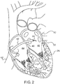
- Fig. 2 is a schematic sectional view of heart 26 showing insertion of catheter 24 into the heart, in accordance with an embodiment of the present invention.
- the operator first passes a sheath 40 percutaneously through the vascular system and into right atrium 44 of the heart through ascending vena cava 42.
- the sheath penetrates through interatrial septum 48, typically via the fossa ovalis, into left atrium 46.
- Catheter 24 is then inserted through the sheath until the distal end of the catheter passes out of the distal opening at the end of the sheath into the left atrium, as shown in the figure.
- Operator 22 aligns the longitudinal axis of sheath 40 and catheter 24 inside left atrium 46 with the axis of one of pulmonary veins 50.
- the operator may carry out this alignment using the position sensing methods described above, along with a pre-acquired map or image of heart 26. Alternatively or additionally, the alignment may be performed under fluoroscopic or other means of visualization.
- the operator inserts the distal tip of the catheter into the target pulmonary vein and brings the catheter tip into contact with the ostium.
- the operator then rotates the catheter about its axis within the sheath in order to trace a circular path around the internal circumference of the vein. Meanwhile, the operator actuates RF generator 36 to ablate the tissue along the path. After completing this procedure in one pulmonary vein, the operator may shift the sheath and catheter and repeat the procedure in one or more of the other pulmonary veins.
- operator 22 may advance and/or retract catheter 24 through sheath 40 in order to trace (and possibly ablate) linear paths along the heart wall, either in left atrium 46 or elsewhere.
- Fig. 3 is a schematic side view showing details of the distal end of catheter 24 within the ostium of pulmonary vein 50, in accordance with an embodiment of the present invention.
- Catheter 24 comprises an insertion tube 62, which is typically made from a biocompatible plastic, such as polyurethane, and contains the functional elements of the catheter.
- the longitudinal axis of the insertion tube (except for the bent distal end) is aligned with the longitudinal axis of sheath 40.
- a resilient member 60 inside the distal end of insertion tube 62 is pre-formed in a bent shape.
- Member 60 may comprise, for example, a strut, rod or tube made from a shape memory material, such as Nitinol, which is produced so as to have this bent shape when unconstrained in its austenitic state. When an inward radial force is exerted against the bent distal end, it straightens toward the longitudinal axis. Thus, within sheath 40 catheter 24 is held straight by the sheath itself. Pressure of the catheter tip against the ostium of vein 50 (or against other tissue) will also tend to straighten the distal end of the catheter.
- Resilient member 60 may be made structurally weak enough to buckle if the pressure against the catheter tip is greater than a certain predetermined threshold, thus giving an extra measure of safety against excessive pressure that could otherwise puncture the vein or heart wall.
- Catheter 24 comprises an electrode 64 at the distal tip of insertion tube 62. This electrode is connected by a conductor (not shown) running through the catheter to RF generator 36, which thus provides RF energy to ablate the tissue with which the electrode is in contact. Rotating catheter 24 about its axis, as illustrated by the circular arrow in Fig. 3 , causes electrode 64 to trace a circular path around the inner circumference of the ostium of vein 50. Operator 22 is thus able to create a circular ablation lesion easily and reliably.
- Catheter 24 comprises position sensors 66 and 68 at different longitudinal locations within the distal end of insertion tube 62.
- sensors 66 and 68 comprise coils, which sense the magnetic fields produced by field generators 32 and output signals to console 30.
- the console process these signals in order to find the location and orientation coordinates of the coils.
- the difference between the orientations of sensors 66 and 68 indicates the bend angle (or equivalently, the curvature) of the distal end of the catheter.
- the bend angle may be measured using position transducers or bend sensors of other types. Additionally or alternatively, operator 22 may observe the bend angle fluoroscopically.
- Console 30 may present an indication of the bend angle, such as a graphical representation of the distal end of the catheter, on display 38. Operator 22 can then control the radial pressure exerted by the catheter against the tissue in heart 26 so that the bend angle remains within a suitable range.
- a small degree of unbending of the distal end of the catheter is desirable to ensure that electrode 64 contacts the tissue firmly; but too much unbending is to be avoided in order to prevent puncturing of the tissue due to excessive pressure.
- the bend angle of the catheter may be monitored and controlled automatically.
- catheter 24 and of system 20 generally may also be used for treatment inside other veins and arteries, as well as in other sorts of body cavities, both tubular and of other shapes. It will thus be appreciated that the embodiments described above are cited by way of example, and that the present invention is not limited to what has been particularly shown and described hereinabove. Rather, the scope of the present invention includes both combinations and subcombinations of the various features described hereinabove, as well as variations and modifications thereof which would occur to persons skilled in the art upon reading the foregoing description and which are not disclosed in the prior art.
- Medical apparatus comprising:
- the catheter comprises an electrode at the distal end, which is configured to contact tissue in the cavity.
- the apparatus comprising a radio frequency (RF) generator, which is coupled to supply RF energy through the catheter to the electrode so as to ablate the tissue.
- RF radio frequency
- the catheter comprises a position transducer in the distal end
- the apparatus comprises a position sensing system, which is configured to communicate with the position transducer so as to determine a location of the distal end within the body.
- a medical device comprising:
- the resilient member comprises a shape memory material.
- the device according to aspect 8 and comprising at least one position transducer in the distal end of the insertion tube.
- the at least one position transducer is configured to measure a bend angle of the distal end of the insertion tube.
- the at least one position transducer comprises two position transducers at different longitudinal locations within the distal end of the insertion tube.
- the resilient member is configured to straighten toward the longitudinal axis when the force is applied in an inward radial force.
- the resilient member is configured to buckle when the radial force exceeds a predetermined threshold.
- Medical apparatus comprising:
- the apparatus comprising a radio frequency (RF) generator, which is coupled to supply RF energy through the medical device to the electrode so as to ablate the tissue.
- RF radio frequency
- the medical device comprises a position transducer in the distal end
- the apparatus comprises a position sensing system, which is configured to communicate with the position transducer so as to determine a location of the distal end within the body.
Abstract
Description
- The present invention relates generally to methods and devices for invasive medical treatment, and specifically to catheters.
- Ablation of myocardial tissue is well known as a treatment for cardiac arrhythmias. In radio-frequency (RF) ablation, for example, a catheter is inserted into the heart and brought into contact with tissue at a target location. RF energy is then applied through an electrode on the catheter in order to create a lesion for the purpose of breaking arrhythmogenic current paths in the tissue.
- Recently, circumferential ablation of the ostia of the pulmonary veins has gained acceptance as a treatment for atrial arrhythmias, and particularly for atrial fibrillation. For example,
U.S. Patent 6,064,902 , whose disclosure is incorporated herein by reference, describes a catheter for ablating tissue on the inner wall of a blood vessel, such as a pulmonary vein. The tip portion of the catheter is deflectable from a first, generally straight, configuration, in which the proximal and distal sections are substantially co-linear, to a second, J-shaped, configuration in which the proximal and distal sections are generally parallel with a separation therebetween substantially corresponding to the inside diameter of the blood vessel. The distal end portion of the catheter is rotated about the longitudinal axis of the catheter to cause a circumferential displacement of proximal and distal ablation electrodes on the catheter along the inner wall of the pulmonary vein. In this way, the electrode catheter may be used to ablate a number of circumferentially-spaced sites on the inner wall of the pulmonary vein by ablating one or two sites at each circumferential position. - Embodiments of the present invention that are described hereinbelow provide invasive devices and methods for contacting tissue within the body with enhanced safety and efficacy.
- There is therefore provided, in accordance with an embodiment of the present invention, a medical device, including an insertion tube, having a longitudinal axis and having a distal end adapted for insertion through a body passage into a cavity within a body of a patient. An electrode is located on the distal end of the insertion tube and is configured to contact tissue in the cavity. A resilient member, which may include a shape memory material, is contained within the distal end of the insertion tube and is configured, when unconstrained, to cause the distal end to bend away from the longitudinal axis in a curved shape and to straighten toward the longitudinal axis when subjected to a force.
- In a disclosed embodiment, the device includes at least one position transducer in the distal end of the insertion tube. The at least one position transducer may be configured to measure a bend angle of the distal end of the insertion tube. In this case, the at least one position transducer typically includes two position transducers at different longitudinal locations within the distal end of the insertion tube.
- Typically, the resilient member is configured to straighten toward the longitudinal axis when the force is applied in an inward radial force. The resilient member may be configured to buckle when the radial force exceeds a predetermined threshold.
- There is also provided, in accordance with an embodiment of the present invention, medical apparatus, including a sheath, which has a longitudinal axis and a distal opening and is adapted for insertion through a body passage into a cavity within a body of a patient. A catheter is configured for insertion through the sheath into the cavity and has a resilient distal end that is formed so that, when unconstrained, the distal end bends away from the longitudinal axis in a curved shape, and when subjected to a force, the distal end straightens toward the longitudinal axis.
- In a disclosed embodiment, the sheath exerts the force in an inward radial direction so as to straighten the distal end of the catheter during passage of the distal end through the sheath, and the distal end of the catheter assumes the curved shape after passing through the distal opening of the sheath into the cavity. Typically, the catheter is configured to rotate about the axis within the sheath.
- In some embodiments, the catheter includes an electrode at the distal end, which is configured to contact tissue in the cavity. The apparatus may include a radio frequency (RF) generator, which is coupled to supply RF energy through the catheter to the electrode so as to ablate the tissue.
- In a disclosed embodiment, the catheter includes a position transducer in the distal end, and the apparatus includes a position sensing system, which is configured to communicate with the position transducer so as to determine a location of the distal end within the body. The position sensing system may be configured to provide an indication of a bend angle of the distal end of the catheter.
- There is additionally provided, in accordance with an embodiment of the present invention, a method for medical treatment, including inserting a sheath, having a longitudinal axis and a distal opening, through a body passage into a cavity within a body of a patient. A catheter is inserted into the sheath, wherein the catheter has a resilient distal end that is formed so that, when unconstrained, the distal end bends away from the longitudinal axis in a curved shape, and when subjected to a force, the distal end straightens toward the longitudinal axis. The catheter is advanced through the sheath so that the distal end of the catheter passes through the distal opening of the sheath into the cavity and assumes the curved shape. The catheter is manipulated within the cavity so that the distal end contacts tissue in the cavity, and the catheter is moved within the sheath while the distal end contacts the tissue so as to cause the distal end to trace a desired path along the tissue.
- In some embodiments, moving the catheter includes rotating the catheter about the axis. In one embodiment, the cavity includes a blood vessel, and rotating the catheter causes the distal end to trace a circular path around an internal circumference of the blood vessel. For example, inserting the sheath may include passing the sheath percutaneously through a vascular system of the patient into a left atrium of a heart of the patient, and advancing the catheter may include positioning the distal end of the catheter in a pulmonary vein so as to trace the circular path within an ostium of the pulmonary vein.
- In a disclosed embodiment, the method includes providing an indication of a bending angle of the distal end of the catheter, and controlling a pressure of the distal end against the tissue responsively to the indication.
- The present invention will be more fully understood from the following detailed description of the embodiments thereof, taken together with the drawings in which:
-
-
Fig. 1 is a schematic pictorial illustration of a system for ablation of tissue in the heart, in accordance with an embodiment of the present invention; -
Fig. 2 is a schematic sectional view of a heart showing insertion of a catheter into the left atrium, in accordance with an embodiment of the present invention; and -
Fig. 3 is a schematic side view of a catheter within the ostium of a pulmonary vein, in accordance with an embodiment of the present invention. - Embodiments of the present invention that are described hereinbelow provide simple, safe, and reliable devices and methods for ablating tissue along a selected path inside a body cavity. Some of these embodiments are particularly suitable for ablating circumferential paths inside a tubular structure, such as a blood vessel. The principles of the present invention may also be applied, however, on linear paths and in applications other than ablation.
- In a disclosed embodiment, a medical device, such as a catheter, comprises an insertion tube, which is inserted through a body passage into a body cavity, such as a chamber of the heart. The insertion tube has an electrode at its distal tip, which makes contact with tissue in the cavity. The distal end of the insertion tube contains a resilient member, such as a shape memory strut, which is pre-formed so as to cause the distal end to bend away from the longitudinal axis of the insertion tube in a curved shape as long as the catheter is not constrained by a radial force. In other words, the unconstrained shape of the distal end of the catheter is bent, and the catheter assumes this shape without the use of any sort of active steering mechanism.
- When a force is applied against the distal tip of the catheter in the appropriate direction, such as an inward radial force, it causes the distal end to straighten toward the longitudinal axis. The bend angle thus gives an indication of the force with which the catheter tip is pressing against the tissue. The distal tip of the catheter may be made structurally weak enough to buckle if the pressure against the tissue is greater than a certain threshold, thus giving an extra measure of safety against excessive pressure that might otherwise puncture the tissue
- This pre-formed curved catheter may be used to ablate tissue along circumferential paths inside the pulmonary veins. For this purpose, a sheath is inserted into the left atrium, typically via the fossa ovalis, and is positioned coaxially with the pulmonary vein in which the ablation is to be performed. The catheter is passed through the sheath (which radially constrains the catheter to remain straight while passing through the sheath) until the distal end of the catheter projects out of the sheath and into the vein. The curved shape of the distal end projecting out of the sheath causes the electrode at the distal tip of the catheter to contact the inner wall of the vein. The angle and length of the curved end of the catheter are chosen so that the distal tip presses against the inner wall of the vein when the longitudinal axis of the sheath and the catheter insertion tube is aligned with the axis of the vein.
- To carry out the ablation, an operator manipulates the catheter so that the electrode contacts the tissue in the ostium of the vein, and then rotates the shaft of the catheter in the sheath while applying RF energy to the electrode. This rotation causes the electrode to move around the inner circumference of the vein in a circular path and to ablate the tissue along the path as it goes. Alternatively, the RF energy may be actuated intermittently to ablate selected points along the path. Further alternatively or in addition to this rotational movement, the physician may apply other movements in order to trace different sorts of paths with the catheter.
-
Fig. 1 is a schematic pictorial illustration of asystem 20 for ablation of tissue in aheart 26 of apatient 28, in accordance with an embodiment of the present invention. Anoperator 22, such as a cardiologist, inserts acatheter 24 through the vascular system ofpatient 28 so that the distal end of the catheter enters a chamber of the patient's heart.Operator 22 advances the catheter so that its distal tip engages endocardial tissue at a desired location or locations, as shown in the figures that follow.Catheter 24 is connected by a suitable connector at its proximal end to aconsole 30. The console comprises aRF generator 36 for applying RF energy through an electrode at the distal tip of the catheter in order to ablate the tissue contacted by the distal tip. Alternatively or additionally,catheter 24 may be used for other diagnostic and/or therapeutic functions, such as intracardiac electrical mapping or other types of ablation therapy. - In the pictured embodiment,
system 20 uses magnetic position sensing to determine position coordinates of the distal end of the catheter insideheart 26. To determine the position coordinates, adriver circuit 34 inconsole 30drives field generators 32 to generate magnetic fields within the body ofpatient 28. Typically,field generators 32 comprise coils, which are placed below the patient's torso at known positions external to the body. These coils generate magnetic fields in a predefined working volume that containsheart 26. One or more magnetic field sensors within the distal end of catheter 24 (as shown inFig. 3 ) generate electrical signals in response to these magnetic fields. The console processes these signals in order to determine the position (location and/or orientation) coordinates of the distal end ofcatheter 24, and possibly also the bend angle, as explained below.Console 30 may use the coordinates in driving adisplay 38 to show the location and status of the catheter. This method of position sensing and processing is implemented, for example, in the CARTO™ system produced by Biosense Webster Inc. (Diamond Bar, California). - Alternatively or additionally,
system 20 may comprise an automated mechanism (not shown) for maneuvering and operatingcatheter 24 within the body ofpatient 28. Such mechanisms are typically capable of controlling both the longitudinal motion (advance/retract) and the rotation ofcatheter 24. In such embodiments,console 30 generates a control input for controlling the motion of the catheter based on the signals provided by the position sensing system. - Although
Fig. 1 shows a particular system configuration, other system configurations may be used in alternative embodiments of the present invention. For example, the methods described hereinbelow may be applied using position transducers of other types, such as impedance-based or ultrasonic position sensors. The term "position transducer" as used herein refers to an element mounted on or incatheter 24 that causesconsole 30 to receive signals indicative of the coordinates of the element. The position transducer may thus comprise a receiver in the catheter, which generates a position signal to the control unit based on energy received by the transducer; or it may comprise a transmitter, emitting energy that is sensed by a receiver external to the probe. Furthermore, the methods described hereinbelow may similarly be applied in mapping and measurement applications using not only catheters, but also probes of other types, both in the heart and in other body organs and regions. -
Fig. 2 is a schematic sectional view ofheart 26 showing insertion ofcatheter 24 into the heart, in accordance with an embodiment of the present invention. To insert the catheter in the pictured embodiment, the operator first passes asheath 40 percutaneously through the vascular system and intoright atrium 44 of the heart through ascendingvena cava 42. The sheath penetrates throughinteratrial septum 48, typically via the fossa ovalis, intoleft atrium 46. Alternatively, other approach paths may be used.Catheter 24 is then inserted through the sheath until the distal end of the catheter passes out of the distal opening at the end of the sheath into the left atrium, as shown in the figure. -
Operator 22 aligns the longitudinal axis ofsheath 40 andcatheter 24 insideleft atrium 46 with the axis of one ofpulmonary veins 50. The operator may carry out this alignment using the position sensing methods described above, along with a pre-acquired map or image ofheart 26. Alternatively or additionally, the alignment may be performed under fluoroscopic or other means of visualization. The operator inserts the distal tip of the catheter into the target pulmonary vein and brings the catheter tip into contact with the ostium. The operator then rotates the catheter about its axis within the sheath in order to trace a circular path around the internal circumference of the vein. Meanwhile, the operator actuatesRF generator 36 to ablate the tissue along the path. After completing this procedure in one pulmonary vein, the operator may shift the sheath and catheter and repeat the procedure in one or more of the other pulmonary veins. - Alternatively or additionally,
operator 22 may advance and/or retractcatheter 24 throughsheath 40 in order to trace (and possibly ablate) linear paths along the heart wall, either inleft atrium 46 or elsewhere. - The above procedures may be carried out without the use of any steering mechanism in catheter 24: Due to the curved shape of the catheter, only advancement/retraction and rotation of the catheter are required. The absence of an internal steering mechanism reduces the size and cost of the catheter relative to devices that are known in the art. As noted earlier, the above procedures may be carried out by an automated mechanism, rather than manually by the operator as illustrated in
Fig. 1 . -
Fig. 3 is a schematic side view showing details of the distal end ofcatheter 24 within the ostium ofpulmonary vein 50, in accordance with an embodiment of the present invention.Catheter 24 comprises aninsertion tube 62, which is typically made from a biocompatible plastic, such as polyurethane, and contains the functional elements of the catheter. The longitudinal axis of the insertion tube (except for the bent distal end) is aligned with the longitudinal axis ofsheath 40. - A
resilient member 60 inside the distal end ofinsertion tube 62 is pre-formed in a bent shape.Member 60 may comprise, for example, a strut, rod or tube made from a shape memory material, such as Nitinol, which is produced so as to have this bent shape when unconstrained in its austenitic state. When an inward radial force is exerted against the bent distal end, it straightens toward the longitudinal axis. Thus, withinsheath 40catheter 24 is held straight by the sheath itself. Pressure of the catheter tip against the ostium of vein 50 (or against other tissue) will also tend to straighten the distal end of the catheter.Resilient member 60 may be made structurally weak enough to buckle if the pressure against the catheter tip is greater than a certain predetermined threshold, thus giving an extra measure of safety against excessive pressure that could otherwise puncture the vein or heart wall. -
Catheter 24 comprises anelectrode 64 at the distal tip ofinsertion tube 62. This electrode is connected by a conductor (not shown) running through the catheter toRF generator 36, which thus provides RF energy to ablate the tissue with which the electrode is in contact. Rotatingcatheter 24 about its axis, as illustrated by the circular arrow inFig. 3 , causeselectrode 64 to trace a circular path around the inner circumference of the ostium ofvein 50.Operator 22 is thus able to create a circular ablation lesion easily and reliably. -
Catheter 24 comprisesposition sensors insertion tube 62. In the embodiment shown inFig. 1 and described above,sensors field generators 32 and output signals to console 30. The console process these signals in order to find the location and orientation coordinates of the coils. The difference between the orientations ofsensors operator 22 may observe the bend angle fluoroscopically. - Reduction of the bend angle (straightening of the distal end) relative to the bend angle of the distal end when unconstrained is indicative of the radial force exerted on the distal tip of
catheter 24 by the tissue with which it is in contact: The harder the operator presses the tip radially against the tissue, the smaller will be the bend angle.Console 30 may present an indication of the bend angle, such as a graphical representation of the distal end of the catheter, ondisplay 38.Operator 22 can then control the radial pressure exerted by the catheter against the tissue inheart 26 so that the bend angle remains within a suitable range. Typically, a small degree of unbending of the distal end of the catheter is desirable to ensure thatelectrode 64 contacts the tissue firmly; but too much unbending is to be avoided in order to prevent puncturing of the tissue due to excessive pressure. Alternatively or additionally, the bend angle of the catheter may be monitored and controlled automatically. - Although the above embodiments relate specifically to treatment in and around the pulmonary veins, the design features of
catheter 24 and ofsystem 20 generally may also be used for treatment inside other veins and arteries, as well as in other sorts of body cavities, both tubular and of other shapes. It will thus be appreciated that the embodiments described above are cited by way of example, and that the present invention is not limited to what has been particularly shown and described hereinabove. Rather, the scope of the present invention includes both combinations and subcombinations of the various features described hereinabove, as well as variations and modifications thereof which would occur to persons skilled in the art upon reading the foregoing description and which are not disclosed in the prior art. - Aspects of the invention not yet claimed:
- Medical apparatus, comprising:
- a sheath, which has a longitudinal axis and a distal opening and is adapted for insertion through a body passage into a cavity within a body of a patient; and
- a catheter, which is configured for insertion through the sheath into the cavity and which has a resilient distal end that is formed so that, when unconstrained, the distal end bends away from the longitudinal axis in a curved shape, and when subjected to a force, the distal end straightens toward the longitudinal axis.
- The apparatus according to aspect 1, wherein the sheath exerts the force in an inward radial direction so as to straighten the distal end of the catheter during passage of the distal end through the sheath, and wherein the distal end of the catheter assumes the curved shape after passing through the distal opening of the sheath into the cavity.
- The apparatus according to aspect 2, wherein the catheter is configured to rotate about the axis within the sheath.
- The apparatus according to aspect 1, wherein the catheter comprises an electrode at the distal end, which is configured to contact tissue in the cavity.
- The apparatus according to aspect 4, and comprising a radio frequency (RF) generator, which is coupled to supply RF energy through the catheter to the electrode so as to ablate the tissue.
- The apparatus according to aspect 1, wherein the catheter comprises a position transducer in the distal end, and wherein the apparatus comprises a position sensing system, which is configured to communicate with the position transducer so as to determine a location of the distal end within the body.
- The apparatus according to aspect 6, wherein the position sensing system is configured to provide an indication of a bend angle of the distal end of the catheter.
- A medical device, comprising:
- an insertion tube, having a longitudinal axis and having a distal end adapted for insertion through a body passage into a cavity within a body of a patient;
- an electrode, which is located on the distal end of the insertion tube and is configured to contact tissue in the cavity; and
- a resilient member, which is contained within the distal end of the insertion tube and is configured, when unconstrained, to cause the distal end to bend away from the longitudinal axis in a curved shape and to straighten toward the longitudinal axis when subjected to a force.
- The device according to aspect 8, wherein the resilient member comprises a shape memory material.
- The device according to aspect 8, and comprising at least one position transducer in the distal end of the insertion tube.
- The device according to aspect 10, wherein the at least one position transducer is configured to measure a bend angle of the distal end of the insertion tube.
- The device according to aspect 11, wherein the at least one position transducer comprises two position transducers at different longitudinal locations within the distal end of the insertion tube.
- The device according to aspect 8, wherein the resilient member is configured to straighten toward the longitudinal axis when the force is applied in an inward radial force.
- The device according to aspect 13, wherein the resilient member is configured to buckle when the radial force exceeds a predetermined threshold.
- Medical apparatus, comprising:
- a sheath, which has a longitudinal axis and a distal opening and is adapted for insertion through a body passage into a cavity within a body of a patient; and
- a medical device as disclosed in aspect 8, which is configured for insertion through the sheath into the cavity.
- The apparatus according to aspect 15, wherein the sheath exerts the force in an inward radial direction so as to straighten the resilient member during passage of the distal end of the insertion tube through the sheath, and wherein the distal end of the insertion tube assumes the curved shape after passing through the distal opening of the sheath into the cavity.
- The apparatus according to aspect 16, wherein the medical device is configured to rotate about the axis within the sheath.
- The apparatus according to aspect 15, and comprising a radio frequency (RF) generator, which is coupled to supply RF energy through the medical device to the electrode so as to ablate the tissue.
- The apparatus according to aspect 15, wherein the medical device comprises a position transducer in the distal end, and wherein the apparatus comprises a position sensing system, which is configured to communicate with the position transducer so as to determine a location of the distal end within the body.
- The apparatus according to aspect 19, wherein the position sensing system is configured to provide an indication of a bend angle of the distal end of the catheter.
Claims (8)
- A medical device, comprising:an insertion tube, having a longitudinal axis and having a distal end adapted for insertion through a body passage into a cavity within a body of a patient;an electrode, which is located on the distal end of the insertion tube and is configured to contact tissue in the cavity; anda resilient member, which is contained within the distal end of the insertion tube and is configured, when unconstrained, to cause the distal end to bend away from the longitudinal axis in a curved shape and to straighten toward the longitudinal axis when subjected to a force,wherein the resilient member is configured to straighten toward the longitudinal axis when the force applied is an inward radial force and wherein the resilient member is made structurally weak such that, if the radial force exceeds a predetermined threshold, the resilient member buckles thereby preventing excessive pressure being exerted by the distal end.
- The device according to claim 1, wherein the resilient member comprises a shape memory material.
- Medical apparatus, comprising:a sheath, which has a longitudinal axis and a distal opening and is adapted for insertion through a body passage into a cavity within a body of a patient; anda medical device as claimed in claim 1, which is configured for insertion through the sheath into the cavity.
- The apparatus according to claim 3, wherein the sheath exerts the force in an inward radial direction so as to straighten the resilient member during passage of the distal end of the insertion tube through the sheath, and wherein the distal end of the insertion tube assumes the curved shape after passing through the distal opening of the sheath into the cavity.
- The apparatus according to claim 4, wherein the medical device is configured to rotate about the axis within the sheath.
- The apparatus according to claim 3, and comprising a radio frequency (RF) generator, which is coupled to supply RF energy through the medical device to the electrode so as to ablate the tissue.
- The apparatus according to claim 3, wherein the medical device comprises a position transducer in the distal end, and wherein the apparatus comprises a position sensing system, which is configured to communicate with the position transducer so as to determine a location of the distal end within the body.
- The apparatus according to claim 7, wherein the position sensing system is configured to provide an indication of a bend angle of the distal end of the catheter.
Applications Claiming Priority (2)
| Application Number | Priority Date | Filing Date | Title |
|---|---|---|---|
| US12/636,064 US9861438B2 (en) | 2009-12-11 | 2009-12-11 | Pre-formed curved ablation catheter |
| EP10252089.7A EP2332476B1 (en) | 2009-12-11 | 2010-12-10 | Pre-formed curved ablation catheter |
Related Parent Applications (2)
| Application Number | Title | Priority Date | Filing Date |
|---|---|---|---|
| EP10252089.7A Division EP2332476B1 (en) | 2009-12-11 | 2010-12-10 | Pre-formed curved ablation catheter |
| EP10252089.7A Division-Into EP2332476B1 (en) | 2009-12-11 | 2010-12-10 | Pre-formed curved ablation catheter |
Publications (2)
| Publication Number | Publication Date |
|---|---|
| EP3219280A1 true EP3219280A1 (en) | 2017-09-20 |
| EP3219280B1 EP3219280B1 (en) | 2018-12-05 |
Family
ID=43662180
Family Applications (3)
| Application Number | Title | Priority Date | Filing Date |
|---|---|---|---|
| EP10252089.7A Active EP2332476B1 (en) | 2009-12-11 | 2010-12-10 | Pre-formed curved ablation catheter |
| EP17162351.5A Active EP3219280B1 (en) | 2009-12-11 | 2010-12-10 | Pre-formed curved ablation catheter |
| EP17162397.8A Withdrawn EP3219281A1 (en) | 2009-12-11 | 2010-12-10 | Pre-formed curved ablation catheter |
Family Applications Before (1)
| Application Number | Title | Priority Date | Filing Date |
|---|---|---|---|
| EP10252089.7A Active EP2332476B1 (en) | 2009-12-11 | 2010-12-10 | Pre-formed curved ablation catheter |
Family Applications After (1)
| Application Number | Title | Priority Date | Filing Date |
|---|---|---|---|
| EP17162397.8A Withdrawn EP3219281A1 (en) | 2009-12-11 | 2010-12-10 | Pre-formed curved ablation catheter |
Country Status (8)
| Country | Link |
|---|---|
| US (3) | US9861438B2 (en) |
| EP (3) | EP2332476B1 (en) |
| JP (1) | JP6099860B2 (en) |
| AU (3) | AU2010241461B2 (en) |
| CA (1) | CA2723041C (en) |
| DK (1) | DK3219280T3 (en) |
| ES (1) | ES2708832T3 (en) |
| IL (2) | IL209452B (en) |
Families Citing this family (28)
| Publication number | Priority date | Publication date | Assignee | Title |
|---|---|---|---|---|
| ES2928065T3 (en) * | 2006-06-28 | 2022-11-15 | Medtronic Ardian Luxembourg | Thermally induced renal neuromodulation systems |
| US8945025B2 (en) | 2011-12-30 | 2015-02-03 | St. Jude Medical, Atrial Fibrillation Division, Inc. | Catheter with atraumatic tip |
| EP3603501A1 (en) | 2012-08-09 | 2020-02-05 | University of Iowa Research Foundation | Catheter systems for surrounding a tissue structure |
| EP3091921B1 (en) | 2014-01-06 | 2019-06-19 | Farapulse, Inc. | Apparatus for renal denervation ablation |
| WO2015171921A2 (en) | 2014-05-07 | 2015-11-12 | Mickelson Steven R | Methods and apparatus for selective tissue ablation |
| KR101549786B1 (en) * | 2014-05-28 | 2015-09-03 | 사회복지법인 삼성생명공익재단 | Method and device for detecting a point of electrode in insertion of human body |
| WO2015192018A1 (en) | 2014-06-12 | 2015-12-17 | Iowa Approach Inc. | Method and apparatus for rapid and selective tissue ablation with cooling |
| WO2015192027A1 (en) | 2014-06-12 | 2015-12-17 | Iowa Approach Inc. | Method and apparatus for rapid and selective transurethral tissue ablation |
| EP3206613B1 (en) | 2014-10-14 | 2019-07-03 | Farapulse, Inc. | Apparatus for rapid and safe pulmonary vein cardiac ablation |
| US10143526B2 (en) * | 2015-11-30 | 2018-12-04 | Auris Health, Inc. | Robot-assisted driving systems and methods |
| US10130423B1 (en) | 2017-07-06 | 2018-11-20 | Farapulse, Inc. | Systems, devices, and methods for focal ablation |
| US10172673B2 (en) | 2016-01-05 | 2019-01-08 | Farapulse, Inc. | Systems devices, and methods for delivery of pulsed electric field ablative energy to endocardial tissue |
| US20170189097A1 (en) | 2016-01-05 | 2017-07-06 | Iowa Approach Inc. | Systems, apparatuses and methods for delivery of ablative energy to tissue |
| US10660702B2 (en) | 2016-01-05 | 2020-05-26 | Farapulse, Inc. | Systems, devices, and methods for focal ablation |
| WO2017136548A1 (en) | 2016-02-04 | 2017-08-10 | Cardiac Pacemakers, Inc. | Delivery system with force sensor for leadless cardiac device |
| CN113616277A (en) | 2016-06-15 | 2021-11-09 | 阿里内克斯股份有限公司 | Device for treating the lateral surface of the nasal cavity |
| WO2017218734A1 (en) | 2016-06-16 | 2017-12-21 | Iowa Approach, Inc. | Systems, apparatuses, and methods for guide wire delivery |
| US9987081B1 (en) | 2017-04-27 | 2018-06-05 | Iowa Approach, Inc. | Systems, devices, and methods for signal generation |
| US10617867B2 (en) | 2017-04-28 | 2020-04-14 | Farapulse, Inc. | Systems, devices, and methods for delivery of pulsed electric field ablative energy to esophageal tissue |
| JP2020533050A (en) | 2017-09-12 | 2020-11-19 | ファラパルス,インコーポレイテッド | Systems, devices, and methods for ventricular focal ablation |
| EP3790486A1 (en) | 2018-05-07 | 2021-03-17 | Farapulse, Inc. | Systems, apparatuses and methods for delivery of ablative energy to tissue |
| JP7399881B2 (en) | 2018-05-07 | 2023-12-18 | ファラパルス,インコーポレイテッド | epicardial ablation catheter |
| CN112118798A (en) | 2018-05-07 | 2020-12-22 | 法拉普尔赛股份有限公司 | Systems, devices, and methods for filtering high voltage noise induced by pulsed electric field ablation |
| WO2020061359A1 (en) | 2018-09-20 | 2020-03-26 | Farapulse, Inc. | Systems, apparatuses, and methods for delivery of pulsed electric field ablative energy to endocardial tissue |
| US10625080B1 (en) | 2019-09-17 | 2020-04-21 | Farapulse, Inc. | Systems, apparatuses, and methods for detecting ectopic electrocardiogram signals during pulsed electric field ablation |
| US11497541B2 (en) | 2019-11-20 | 2022-11-15 | Boston Scientific Scimed, Inc. | Systems, apparatuses, and methods for protecting electronic components from high power noise induced by high voltage pulses |
| US11065047B2 (en) | 2019-11-20 | 2021-07-20 | Farapulse, Inc. | Systems, apparatuses, and methods for protecting electronic components from high power noise induced by high voltage pulses |
| US10842572B1 (en) | 2019-11-25 | 2020-11-24 | Farapulse, Inc. | Methods, systems, and apparatuses for tracking ablation devices and generating lesion lines |
Citations (7)
| Publication number | Priority date | Publication date | Assignee | Title |
|---|---|---|---|---|
| US6064902A (en) | 1998-04-16 | 2000-05-16 | C.R. Bard, Inc. | Pulmonary vein ablation catheter |
| US6272371B1 (en) * | 1997-01-03 | 2001-08-07 | Biosense Inc. | Bend-responsive catheter |
| WO2002038064A1 (en) * | 2000-11-09 | 2002-05-16 | Super Dimension Ltd. | Apparatus and method for intrabodily treatment |
| US20020183638A1 (en) * | 1995-07-28 | 2002-12-05 | Swanson David K. | Systems and methods for conducting electrophysiological testing using high-voltage energy pulses to stun tissue |
| US6542781B1 (en) * | 1999-11-22 | 2003-04-01 | Scimed Life Systems, Inc. | Loop structures for supporting diagnostic and therapeutic elements in contact with body tissue |
| US20060241366A1 (en) * | 2002-10-31 | 2006-10-26 | Gary Falwell | Electrophysiology loop catheter |
| EP2047797A2 (en) * | 2007-10-08 | 2009-04-15 | Biosense Webster, Inc. | Catheter with pressure sensing |
Family Cites Families (26)
| Publication number | Priority date | Publication date | Assignee | Title |
|---|---|---|---|---|
| US4671795A (en) * | 1984-11-19 | 1987-06-09 | Mulchin William L | Permanent/retrievable ureteral catheter |
| US5109830A (en) * | 1990-04-10 | 1992-05-05 | Candela Laser Corporation | Apparatus for navigation of body cavities |
| ATE219908T1 (en) * | 1993-04-28 | 2002-07-15 | Biosense Webster Inc | ELECTROPHYSIOLOGY CATHETER WITH PRE-BENT TIP |
| US5487385A (en) * | 1993-12-03 | 1996-01-30 | Avitall; Boaz | Atrial mapping and ablation catheter system |
| WO1996034646A1 (en) * | 1995-05-01 | 1996-11-07 | Medtronic Cardiorhythm | Dual curve ablation catheter and method |
| US5823955A (en) * | 1995-11-20 | 1998-10-20 | Medtronic Cardiorhythm | Atrioventricular valve tissue ablation catheter and method |
| DE898480T1 (en) * | 1996-01-19 | 1999-10-07 | Scimed Life Systems Inc | CATHETER WITH A CURVE WITH INCREASING RADIUS |
| US5882346A (en) * | 1996-07-15 | 1999-03-16 | Cardiac Pathways Corporation | Shapable catheter using exchangeable core and method of use |
| ES2216180T3 (en) * | 1997-01-03 | 2004-10-16 | Biosense, Inc. | CONFORMATIONAL CATHETER. |
| US6146381A (en) * | 1998-05-05 | 2000-11-14 | Cardiac Pacemakers, Inc. | Catheter having distal region for deflecting axial forces |
| US6652517B1 (en) * | 2000-04-25 | 2003-11-25 | Uab Research Foundation | Ablation catheter, system, and method of use thereof |
| JP2002191571A (en) | 2000-12-26 | 2002-07-09 | Hisayuki Mukai | Electrode catheter |
| US6972016B2 (en) | 2001-05-01 | 2005-12-06 | Cardima, Inc. | Helically shaped electrophysiology catheter |
| US6973339B2 (en) * | 2003-07-29 | 2005-12-06 | Biosense, Inc | Lasso for pulmonary vein mapping and ablation |
| US7824345B2 (en) | 2003-12-22 | 2010-11-02 | Boston Scientific Scimed, Inc. | Medical device with push force limiter |
| US7122034B2 (en) * | 2004-05-27 | 2006-10-17 | St. Jude Medical, Atrial Fibrillation Division, Inc. | Curved ablation catheter |
| US7250049B2 (en) * | 2004-05-27 | 2007-07-31 | St. Jude Medical, Atrial Fibrillation Division, Inc. | Ablation catheter with suspension system incorporating rigid and flexible components |
| US9320564B2 (en) | 2005-05-05 | 2016-04-26 | Boston Scientific Scimed Inc. | Steerable catheter and method for performing medical procedure adjacent pulmonary vein ostia |
| US20070062546A1 (en) * | 2005-06-02 | 2007-03-22 | Viswanathan Raju R | Electrophysiology catheter and system for gentle and firm wall contact |
| JP2009500052A (en) | 2005-06-20 | 2009-01-08 | アブレーション フロンティアズ,インコーポレーテッド | Ablation catheter |
| US7623899B2 (en) * | 2005-09-16 | 2009-11-24 | Biosense Webster, Inc. | Catheter with flexible pre-shaped tip section |
| US20070161882A1 (en) * | 2006-01-06 | 2007-07-12 | Carlo Pappone | Electrophysiology catheter and system for gentle and firm wall contact |
| US8437832B2 (en) * | 2008-06-06 | 2013-05-07 | Biosense Webster, Inc. | Catheter with bendable tip |
| US8926604B2 (en) * | 2009-12-23 | 2015-01-06 | Biosense Webster (Israel) Ltd. | Estimation and mapping of ablation volume |
| US8608735B2 (en) * | 2009-12-30 | 2013-12-17 | Biosense Webster (Israel) Ltd. | Catheter with arcuate end section |
| US9308041B2 (en) * | 2010-12-22 | 2016-04-12 | Biosense Webster (Israel) Ltd. | Lasso catheter with rotating ultrasound transducer |
-
2009
- 2009-12-11 US US12/636,064 patent/US9861438B2/en active Active
-
2010
- 2010-11-16 AU AU2010241461A patent/AU2010241461B2/en not_active Ceased
- 2010-11-18 IL IL209452A patent/IL209452B/en active IP Right Grant
- 2010-11-30 CA CA2723041A patent/CA2723041C/en not_active Expired - Fee Related
- 2010-12-10 DK DK17162351.5T patent/DK3219280T3/en active
- 2010-12-10 EP EP10252089.7A patent/EP2332476B1/en active Active
- 2010-12-10 ES ES17162351T patent/ES2708832T3/en active Active
- 2010-12-10 JP JP2010275491A patent/JP6099860B2/en not_active Expired - Fee Related
- 2010-12-10 EP EP17162351.5A patent/EP3219280B1/en active Active
- 2010-12-10 EP EP17162397.8A patent/EP3219281A1/en not_active Withdrawn
-
2013
- 2013-02-12 US US13/765,006 patent/US9439727B2/en active Active
- 2013-02-12 US US13/765,044 patent/US8926589B2/en active Active
-
2015
- 2015-06-01 AU AU2015202963A patent/AU2015202963B2/en not_active Ceased
- 2015-06-01 AU AU2015202961A patent/AU2015202961B2/en not_active Ceased
-
2018
- 2018-02-21 IL IL257657A patent/IL257657B/en active IP Right Grant
Patent Citations (7)
| Publication number | Priority date | Publication date | Assignee | Title |
|---|---|---|---|---|
| US20020183638A1 (en) * | 1995-07-28 | 2002-12-05 | Swanson David K. | Systems and methods for conducting electrophysiological testing using high-voltage energy pulses to stun tissue |
| US6272371B1 (en) * | 1997-01-03 | 2001-08-07 | Biosense Inc. | Bend-responsive catheter |
| US6064902A (en) | 1998-04-16 | 2000-05-16 | C.R. Bard, Inc. | Pulmonary vein ablation catheter |
| US6542781B1 (en) * | 1999-11-22 | 2003-04-01 | Scimed Life Systems, Inc. | Loop structures for supporting diagnostic and therapeutic elements in contact with body tissue |
| WO2002038064A1 (en) * | 2000-11-09 | 2002-05-16 | Super Dimension Ltd. | Apparatus and method for intrabodily treatment |
| US20060241366A1 (en) * | 2002-10-31 | 2006-10-26 | Gary Falwell | Electrophysiology loop catheter |
| EP2047797A2 (en) * | 2007-10-08 | 2009-04-15 | Biosense Webster, Inc. | Catheter with pressure sensing |
Also Published As
| Publication number | Publication date |
|---|---|
| EP3219280B1 (en) | 2018-12-05 |
| US9861438B2 (en) | 2018-01-09 |
| JP2011120912A (en) | 2011-06-23 |
| US9439727B2 (en) | 2016-09-13 |
| AU2010241461B2 (en) | 2016-02-25 |
| CA2723041C (en) | 2019-03-26 |
| AU2015202961A1 (en) | 2015-06-25 |
| JP6099860B2 (en) | 2017-03-22 |
| EP2332476A1 (en) | 2011-06-15 |
| AU2015202963B2 (en) | 2017-06-29 |
| IL257657B (en) | 2020-03-31 |
| AU2015202963A1 (en) | 2015-06-18 |
| IL257657A (en) | 2018-04-30 |
| US20130158539A1 (en) | 2013-06-20 |
| US20110144633A1 (en) | 2011-06-16 |
| DK3219280T3 (en) | 2019-02-25 |
| ES2708832T3 (en) | 2019-04-11 |
| AU2015202961B2 (en) | 2016-08-11 |
| EP3219281A1 (en) | 2017-09-20 |
| EP2332476B1 (en) | 2017-05-10 |
| US20130158538A1 (en) | 2013-06-20 |
| CA2723041A1 (en) | 2011-06-11 |
| AU2010241461A1 (en) | 2011-06-30 |
| US8926589B2 (en) | 2015-01-06 |
| IL209452A0 (en) | 2011-01-31 |
| IL209452B (en) | 2018-03-29 |
| CN102090924A (en) | 2011-06-15 |
Similar Documents
| Publication | Publication Date | Title |
|---|---|---|
| AU2015202961B2 (en) | Pre-formed curved ablation catheter | |
| AU2018204229B2 (en) | Lasso catheter with tip electrode | |
| AU2010257390B2 (en) | Catheter with arcuate end section |
Legal Events
| Date | Code | Title | Description |
|---|---|---|---|
| PUAI | Public reference made under article 153(3) epc to a published international application that has entered the european phase |
Free format text: ORIGINAL CODE: 0009012 |
|
| AC | Divisional application: reference to earlier application |
Ref document number: 2332476 Country of ref document: EP Kind code of ref document: P |
|
| AK | Designated contracting states |
Kind code of ref document: A1 Designated state(s): AL AT BE BG CH CY CZ DE DK EE ES FI FR GB GR HR HU IE IS IT LI LT LU LV MC MK MT NL NO PL PT RO RS SE SI SK SM TR |
|
| 17P | Request for examination filed |
Effective date: 20180227 |
|
| RBV | Designated contracting states (corrected) |
Designated state(s): AL AT BE BG CH CY CZ DE DK EE ES FI FR GB GR HR HU IE IS IT LI LT LU LV MC MK MT NL NO PL PT RO RS SE SI SK SM TR |
|
| GRAP | Despatch of communication of intention to grant a patent |
Free format text: ORIGINAL CODE: EPIDOSNIGR1 |
|
| RIC1 | Information provided on ipc code assigned before grant |
Ipc: A61B 34/20 20160101ALN20180522BHEP Ipc: A61B 18/14 20060101AFI20180522BHEP Ipc: A61B 90/00 20160101ALN20180522BHEP |
|
| INTG | Intention to grant announced |
Effective date: 20180608 |
|
| GRAS | Grant fee paid |
Free format text: ORIGINAL CODE: EPIDOSNIGR3 |
|
| GRAA | (expected) grant |
Free format text: ORIGINAL CODE: 0009210 |
|
| AC | Divisional application: reference to earlier application |
Ref document number: 2332476 Country of ref document: EP Kind code of ref document: P |
|
| AK | Designated contracting states |
Kind code of ref document: B1 Designated state(s): AL AT BE BG CH CY CZ DE DK EE ES FI FR GB GR HR HU IE IS IT LI LT LU LV MC MK MT NL NO PL PT RO RS SE SI SK SM TR |
|
| REG | Reference to a national code |
Ref country code: GB Ref legal event code: FG4D |
|
| REG | Reference to a national code |
Ref country code: CH Ref legal event code: EP |
|
| REG | Reference to a national code |
Ref country code: AT Ref legal event code: REF Ref document number: 1072095 Country of ref document: AT Kind code of ref document: T Effective date: 20181215 |
|
| REG | Reference to a national code |
Ref country code: IE Ref legal event code: FG4D |
|
| REG | Reference to a national code |
Ref country code: DE Ref legal event code: R096 Ref document number: 602010055719 Country of ref document: DE |
|
| REG | Reference to a national code |
Ref country code: SE Ref legal event code: TRGR |
|
| REG | Reference to a national code |
Ref country code: DK Ref legal event code: T3 Effective date: 20190221 |
|
| REG | Reference to a national code |
Ref country code: NL Ref legal event code: FP |
|
| REG | Reference to a national code |
Ref country code: ES Ref legal event code: FG2A Ref document number: 2708832 Country of ref document: ES Kind code of ref document: T3 Effective date: 20190411 |
|
| REG | Reference to a national code |
Ref country code: AT Ref legal event code: MK05 Ref document number: 1072095 Country of ref document: AT Kind code of ref document: T Effective date: 20181205 |
|
| REG | Reference to a national code |
Ref country code: LT Ref legal event code: MG4D |
|
| PG25 | Lapsed in a contracting state [announced via postgrant information from national office to epo] |
Ref country code: AT Free format text: LAPSE BECAUSE OF FAILURE TO SUBMIT A TRANSLATION OF THE DESCRIPTION OR TO PAY THE FEE WITHIN THE PRESCRIBED TIME-LIMIT Effective date: 20181205 Ref country code: LV Free format text: LAPSE BECAUSE OF FAILURE TO SUBMIT A TRANSLATION OF THE DESCRIPTION OR TO PAY THE FEE WITHIN THE PRESCRIBED TIME-LIMIT Effective date: 20181205 Ref country code: FI Free format text: LAPSE BECAUSE OF FAILURE TO SUBMIT A TRANSLATION OF THE DESCRIPTION OR TO PAY THE FEE WITHIN THE PRESCRIBED TIME-LIMIT Effective date: 20181205 Ref country code: BG Free format text: LAPSE BECAUSE OF FAILURE TO SUBMIT A TRANSLATION OF THE DESCRIPTION OR TO PAY THE FEE WITHIN THE PRESCRIBED TIME-LIMIT Effective date: 20190305 Ref country code: HR Free format text: LAPSE BECAUSE OF FAILURE TO SUBMIT A TRANSLATION OF THE DESCRIPTION OR TO PAY THE FEE WITHIN THE PRESCRIBED TIME-LIMIT Effective date: 20181205 Ref country code: NO Free format text: LAPSE BECAUSE OF FAILURE TO SUBMIT A TRANSLATION OF THE DESCRIPTION OR TO PAY THE FEE WITHIN THE PRESCRIBED TIME-LIMIT Effective date: 20190305 Ref country code: LT Free format text: LAPSE BECAUSE OF FAILURE TO SUBMIT A TRANSLATION OF THE DESCRIPTION OR TO PAY THE FEE WITHIN THE PRESCRIBED TIME-LIMIT Effective date: 20181205 |
|
| PG25 | Lapsed in a contracting state [announced via postgrant information from national office to epo] |
Ref country code: RS Free format text: LAPSE BECAUSE OF FAILURE TO SUBMIT A TRANSLATION OF THE DESCRIPTION OR TO PAY THE FEE WITHIN THE PRESCRIBED TIME-LIMIT Effective date: 20181205 Ref country code: GR Free format text: LAPSE BECAUSE OF FAILURE TO SUBMIT A TRANSLATION OF THE DESCRIPTION OR TO PAY THE FEE WITHIN THE PRESCRIBED TIME-LIMIT Effective date: 20190306 Ref country code: AL Free format text: LAPSE BECAUSE OF FAILURE TO SUBMIT A TRANSLATION OF THE DESCRIPTION OR TO PAY THE FEE WITHIN THE PRESCRIBED TIME-LIMIT Effective date: 20181205 |
|
| PG25 | Lapsed in a contracting state [announced via postgrant information from national office to epo] |
Ref country code: PL Free format text: LAPSE BECAUSE OF FAILURE TO SUBMIT A TRANSLATION OF THE DESCRIPTION OR TO PAY THE FEE WITHIN THE PRESCRIBED TIME-LIMIT Effective date: 20181205 Ref country code: PT Free format text: LAPSE BECAUSE OF FAILURE TO SUBMIT A TRANSLATION OF THE DESCRIPTION OR TO PAY THE FEE WITHIN THE PRESCRIBED TIME-LIMIT Effective date: 20190405 |
|
| PG25 | Lapsed in a contracting state [announced via postgrant information from national office to epo] |
Ref country code: SK Free format text: LAPSE BECAUSE OF FAILURE TO SUBMIT A TRANSLATION OF THE DESCRIPTION OR TO PAY THE FEE WITHIN THE PRESCRIBED TIME-LIMIT Effective date: 20181205 Ref country code: RO Free format text: LAPSE BECAUSE OF FAILURE TO SUBMIT A TRANSLATION OF THE DESCRIPTION OR TO PAY THE FEE WITHIN THE PRESCRIBED TIME-LIMIT Effective date: 20181205 Ref country code: IS Free format text: LAPSE BECAUSE OF FAILURE TO SUBMIT A TRANSLATION OF THE DESCRIPTION OR TO PAY THE FEE WITHIN THE PRESCRIBED TIME-LIMIT Effective date: 20190405 Ref country code: EE Free format text: LAPSE BECAUSE OF FAILURE TO SUBMIT A TRANSLATION OF THE DESCRIPTION OR TO PAY THE FEE WITHIN THE PRESCRIBED TIME-LIMIT Effective date: 20181205 Ref country code: SM Free format text: LAPSE BECAUSE OF FAILURE TO SUBMIT A TRANSLATION OF THE DESCRIPTION OR TO PAY THE FEE WITHIN THE PRESCRIBED TIME-LIMIT Effective date: 20181205 Ref country code: LU Free format text: LAPSE BECAUSE OF NON-PAYMENT OF DUE FEES Effective date: 20181210 |
|
| REG | Reference to a national code |
Ref country code: DE Ref legal event code: R097 Ref document number: 602010055719 Country of ref document: DE |
|
| PLBE | No opposition filed within time limit |
Free format text: ORIGINAL CODE: 0009261 |
|
| STAA | Information on the status of an ep patent application or granted ep patent |
Free format text: STATUS: NO OPPOSITION FILED WITHIN TIME LIMIT |
|
| PG25 | Lapsed in a contracting state [announced via postgrant information from national office to epo] |
Ref country code: SI Free format text: LAPSE BECAUSE OF FAILURE TO SUBMIT A TRANSLATION OF THE DESCRIPTION OR TO PAY THE FEE WITHIN THE PRESCRIBED TIME-LIMIT Effective date: 20181205 Ref country code: MC Free format text: LAPSE BECAUSE OF FAILURE TO SUBMIT A TRANSLATION OF THE DESCRIPTION OR TO PAY THE FEE WITHIN THE PRESCRIBED TIME-LIMIT Effective date: 20181205 |
|
| 26N | No opposition filed |
Effective date: 20190906 |
|
| PG25 | Lapsed in a contracting state [announced via postgrant information from national office to epo] |
Ref country code: MT Free format text: LAPSE BECAUSE OF NON-PAYMENT OF DUE FEES Effective date: 20181210 |
|
| PG25 | Lapsed in a contracting state [announced via postgrant information from national office to epo] |
Ref country code: TR Free format text: LAPSE BECAUSE OF FAILURE TO SUBMIT A TRANSLATION OF THE DESCRIPTION OR TO PAY THE FEE WITHIN THE PRESCRIBED TIME-LIMIT Effective date: 20181205 |
|
| PG25 | Lapsed in a contracting state [announced via postgrant information from national office to epo] |
Ref country code: MK Free format text: LAPSE BECAUSE OF NON-PAYMENT OF DUE FEES Effective date: 20181205 Ref country code: CY Free format text: LAPSE BECAUSE OF FAILURE TO SUBMIT A TRANSLATION OF THE DESCRIPTION OR TO PAY THE FEE WITHIN THE PRESCRIBED TIME-LIMIT Effective date: 20181205 Ref country code: HU Free format text: LAPSE BECAUSE OF FAILURE TO SUBMIT A TRANSLATION OF THE DESCRIPTION OR TO PAY THE FEE WITHIN THE PRESCRIBED TIME-LIMIT; INVALID AB INITIO Effective date: 20101210 |
|
| PGFP | Annual fee paid to national office [announced via postgrant information from national office to epo] |
Ref country code: DK Payment date: 20201210 Year of fee payment: 11 Ref country code: CZ Payment date: 20201119 Year of fee payment: 11 Ref country code: IE Payment date: 20201209 Year of fee payment: 11 Ref country code: SE Payment date: 20201211 Year of fee payment: 11 Ref country code: CH Payment date: 20201215 Year of fee payment: 11 |
|
| PGFP | Annual fee paid to national office [announced via postgrant information from national office to epo] |
Ref country code: BE Payment date: 20201116 Year of fee payment: 11 |
|
| PGFP | Annual fee paid to national office [announced via postgrant information from national office to epo] |
Ref country code: ES Payment date: 20210111 Year of fee payment: 11 |
|
| REG | Reference to a national code |
Ref country code: DK Ref legal event code: EBP Effective date: 20211231 |
|
| PG25 | Lapsed in a contracting state [announced via postgrant information from national office to epo] |
Ref country code: CZ Free format text: LAPSE BECAUSE OF NON-PAYMENT OF DUE FEES Effective date: 20211210 |
|
| REG | Reference to a national code |
Ref country code: CH Ref legal event code: PL |
|
| REG | Reference to a national code |
Ref country code: SE Ref legal event code: EUG |
|
| REG | Reference to a national code |
Ref country code: BE Ref legal event code: MM Effective date: 20211231 |
|
| PG25 | Lapsed in a contracting state [announced via postgrant information from national office to epo] |
Ref country code: SE Free format text: LAPSE BECAUSE OF NON-PAYMENT OF DUE FEES Effective date: 20211211 Ref country code: IE Free format text: LAPSE BECAUSE OF NON-PAYMENT OF DUE FEES Effective date: 20211210 |
|
| PG25 | Lapsed in a contracting state [announced via postgrant information from national office to epo] |
Ref country code: BE Free format text: LAPSE BECAUSE OF NON-PAYMENT OF DUE FEES Effective date: 20211231 |
|
| PG25 | Lapsed in a contracting state [announced via postgrant information from national office to epo] |
Ref country code: LI Free format text: LAPSE BECAUSE OF NON-PAYMENT OF DUE FEES Effective date: 20211231 Ref country code: CH Free format text: LAPSE BECAUSE OF NON-PAYMENT OF DUE FEES Effective date: 20211231 |
|
| PG25 | Lapsed in a contracting state [announced via postgrant information from national office to epo] |
Ref country code: DK Free format text: LAPSE BECAUSE OF NON-PAYMENT OF DUE FEES Effective date: 20211231 |
|
| PGFP | Annual fee paid to national office [announced via postgrant information from national office to epo] |
Ref country code: NL Payment date: 20221114 Year of fee payment: 13 Ref country code: IT Payment date: 20221111 Year of fee payment: 13 Ref country code: GB Payment date: 20221103 Year of fee payment: 13 Ref country code: FR Payment date: 20221110 Year of fee payment: 13 Ref country code: DE Payment date: 20220622 Year of fee payment: 13 |
|
| REG | Reference to a national code |
Ref country code: ES Ref legal event code: FD2A Effective date: 20230224 |
|
| PG25 | Lapsed in a contracting state [announced via postgrant information from national office to epo] |
Ref country code: ES Free format text: LAPSE BECAUSE OF NON-PAYMENT OF DUE FEES Effective date: 20211211 |