US1237403A - Automatic instantaneous water heating and storage system. - Google Patents
Automatic instantaneous water heating and storage system. Download PDFInfo
- Publication number
- US1237403A US1237403A US81318514A US1914813185A US1237403A US 1237403 A US1237403 A US 1237403A US 81318514 A US81318514 A US 81318514A US 1914813185 A US1914813185 A US 1914813185A US 1237403 A US1237403 A US 1237403A
- Authority
- US
- United States
- Prior art keywords
- water
- heater
- container
- heaters
- heating
- Prior art date
- Legal status (The legal status is an assumption and is not a legal conclusion. Google has not performed a legal analysis and makes no representation as to the accuracy of the status listed.)
- Expired - Lifetime
Links
Images

Classifications
-
- F—MECHANICAL ENGINEERING; LIGHTING; HEATING; WEAPONS; BLASTING
- F24—HEATING; RANGES; VENTILATING
- F24H—FLUID HEATERS, e.g. WATER OR AIR HEATERS, HAVING HEAT-GENERATING MEANS, e.g. HEAT PUMPS, IN GENERAL
- F24H1/00—Water heaters, e.g. boilers, continuous-flow heaters or water-storage heaters
- F24H1/18—Water-storage heaters
- F24H1/20—Water-storage heaters with immersed heating elements, e.g. electric elements or furnace tubes
- F24H1/205—Water-storage heaters with immersed heating elements, e.g. electric elements or furnace tubes with furnace tubes
Definitions
- I. g I -5 :12 52 u W6 37? ease-5*: 1 1) k RY/077E07 6 857726? akmwk fifzw fr v when the demand is light, or by which the ELMER s. STACK, or somnnvrnnn, MASSACHUSETTS.
- the object of the present application is to provide a waterheating apparatus which is capable of supplying heated water in either large or small quantities according to the demands made upon the apparatus.
- a waterheating apparatus which is capable of supplying heated water in either large or small quantities according to the demands made upon the apparatus.
- my general object is to provide an apparatus from which water sufiiciently hot to meet the requirements of the service can beobtained at any instant and in any quantities required, under circumstances where the demands as to quantity vary within exceedingly wide limits. It is also a part of my object to provide such a heating apparatus for a circulating hot water system, bywhich the Water in the whole. system may be kept.
- the invention briefly stated consists in the combination of a hot water container, with a plurality of water heaters, and automatic means for putting one or more'ofsuch heaters into or out of operation according to the demands made upon theapparatus.
- a hot water container with a plurality of water heaters, and automatic means for putting one or more'ofsuch heaters into or out of operation according to the demands made upon theapparatus.
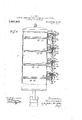
- Figure 1 is an elevation showing in a somewhat diagrammatic manner the entire apparatus.
- Fig. 2 is an elevation partly in section showing in detail a form of water heater which I propose to use in connection with and as one of the elements of my apparatus.
- Fig. 3 is a vertical sectional view of the water container illustrating a form of automatic means for putting the several heaters successively into and out of operation.
- l represents a container adapted to contain a body of water, such container being of the general character commonly employed for domestic use. It is equipped with an inlet pipe 2 for supplying water to be heated, which pipe extends into the container Well toward the bottom thereof, and with hot water circulating pipes 3 and :1, one of which is the outlet pipe for conducting the heated water to the places where such water is to be used, and the other of which is the return pipe.
- Such heaters are 'fed with the colder water from the bottom of the tank, supplied by a pipe 9 from which branches 10,- 11, 12 and 13 lead to the several heaters.
- the hot waterdelivered from the heaters flows from outlet pipes 14, 15, 16 and 17 respectively, all of g which pipes are shown as joined with a single connecting pipe or conduit leading backto the tank at or near the upper end thereof where the hot water collects.
- present invention is not limited to the means by which the hot water is delivered from the heaters tothe tank or tothe hot water supply pipes.
- Thewater from the heaters may be delivered in other ways than that herein illustrated, such as by separate connections from each heater leading independently to the tank, or to-the hot water delivering pipes outside of the tank, orthe conduit 18 or its equivalent may be connected to one or more of the pipes which conduct the heated water from the tank. If the hot water delivery conduits from the heaters are connected to the outlet pipes from the tank outside of the tank, I would prefer to use for the purpose of so connecting them a connection having the characteristics of the connection shown and described in my United States patent for water connections,-No. 1,109,946, granted September 8,1914.
- any satisfactory water heater may be used for the purposes of this invention, and I do not therefore restrict this invention to a combination of any particular heater with the other elements of the combinationf I may say, however, that the type of heater which I prefer to use is that of which the principles are set forth in my patent of the United States No. 1,125,758, granted J anuary 19, 1915, for water heater. Such heater, which is shown somewhat in detail in Fig.
- a bottom header 19 includes a top header, not shown but similar and oppositely arranged to the bottom header, and a cluster of tubes 20 extending from one header to the other in nearly direct lines so as to permit a free and rapid flow of water, but somewhat inclined so as to cross and intercept the currents of heated gases rising from a gas burner 21 suitably arranged in the base of the heater.
- the heater illustrated in Fig. 2 is the heater 5
- the supply pipe 10 through which cool water from the bottom of the tank 1 is conducted leads to the lower header 19, and that the hot water outlet pipe 14 leads from the upper header.
- All the other heaters shown may be .and preferably are duplicates of the heater 5 here particularly described.
- Each heater- has its own independent gas burner 21, and these burners of the several heaters are fed respectively by supply pipes 22, 23, 24 and 25 which lead or may lead from a common gas main 26 and are so placed as to cooperate with thermostatic valve controlling means governed by the heat of the water in the tank and locatedat respectively'different levels in the tank.
- thermostatic valve controlling means for the purpose of illustrating an'operative means of this character, I have shown a particular thermostatic mechanism which I will now describe, choosing for this detailed description the particular thermostatic device which controls the flow ofgas through the pipe 22 to the heater 5.
- This controlling device includes a valve casing or housing 27 which is mounted externally upon or near the tank 1 and is provided with two internal chambers, 28 and 29, respectively. 'To one of these chambers is connected that portion of the pipe or conduit 22 which leads from the main and is here particularly designated as 22, and from the other of these chambers leads the part 22 of the conduit which runs to the heater.
- the thermostatic element consists of a tube 32 extending through the wall of the tank into the interior thereof, and containing a rod 33 fastened to the inner end of the tube.
- Such rod acts through multiplying levers 34 and 35 pivoted upon brackets which form part of the valve casing structure, the former lever being directly acted upon by the rod and in turn actin on the second lever, and the latter lever eing engaged with the stem 36 of the gas valve and arranged to bear against an adjustable abutment 37 thereon.
- thermostatic tube contracts upon cooling, it exerts a thrust on the rod 33 which bears on the short arm of the lever 34.
- the long arm of the lever acts on the short arm of the lever 35, and the long arm of the latter moves the valve 30 against the pressure of the spring 31 in the direction which causes the valve to be opened.
- gas is admitted to the burner of the heater which is controlled thereby.
- Expansion of the tube 32 due to heating relieves the rod 38 and allows the spring 31 to close the valve.
- the thermostatic controlling means for the burners of the other heaters are shown here as being the same as the controlling means above described, and their several parts are designated by the same reference characters as'the correspond ing parts of the device above described.
- the thermostat controlling the gas supply for the heater 5 is at a high level in the tank 1, that the thermostat for the heater 6 is at a lower level, that for. the heater 7 at a still lower level, that for the heater 8 at the lowest level of all.
- this heater If the capacity of' this heater is not sufficient to supply the demand for hot water, the next thermostat is actuated and the next heater in the series is made operative, and so on until all the heaters are put into operation if the demand is great enough to require-the cooperation of i Similarly, if the body of so many heaters. water in the tank becomes cool by radiation, the cooler water settles in the bottom of the tank and when its temperature is sufliciently low the heater 8 is put in operation for a period long enough to raise the tank tem'- perature to the desired point, when it is again automatically discontinued.
- the gas burner may beconsidered as typical of some or any heating means or device, the combustible gas or fuel for supplying the burner as being typical of any heating agent which might be used for supplying or gencrating heat, and the thermostatic controlheater, causing contractionof the lowermost trol the supply of heatingagent to the heaters and being themselves controlled by the temperature of the water in the tank.
- the thermostatic controlheater causing contractionof the lowermost trol the supply of heatingagent to the heaters and being themselves controlled by the temperature of the water in the tank.
- valves than those herein illustrated and par ticularly described.
- the pipe connections may otherwise be arranged in different manners, all of which are within the scope of my invention, provided the essential principle is maintained of. having a series of heaters which are controlled in operation 7 according to the temperature of the fluid to be heated in different parts of the tank or container.
- My heating apparatus is equally applicable to a circulating hot water system, wherein the pipes with which the hot water taps or faucets are connected form a circuit with the water container and permit a continuous gravity thermal flow, whereby hot water is always accessible to all the taps, even those most distant from the heater.
- My a paratus which includes the combination 0 a plurality of heating elements with a water container, permits a relatively-very small container to be used in a circulating system upon whichthe demands may be very sudden and great.
- my system I can employ a water container hav-- mg only asmall fraction'of the volume of the tank required under the old system;
- the other commonly used means for the purpose specified is an instantaneous Water heater which is put in operation only when water is drawn, and has a large enough fuel burner to heat the water to the desired temperature when the maximum flow passes through the heater.
- a heater cannot be connected with a circulating system, and therefore the water in the pipe between the heater and the tap is allowed to cool off when no water is being drawn. Thereupon when one desires even a small quantity of hot water he must draw off the cold water already in the pipe before the hot water flows, and the burner of the heater is operating at full capacity during all this time, wasting fuel and heating enough water riot only to supply the demand of the user but also to take the place of the cold water previously lying dead in the pipe system.
- Another advantage of my system is that if any part of any heater should fail and require repairs the entire 4 quantity of liquid, a plurality of heating devices connected in parallel with said container, and means controlled by the temperature of the liquid in diflerent levels in the container for putting said heating devices successively into and out of operation.
- a liquid. heating and storage system comprising in combination a container adapted to liquid, a series of liquid heating devices arranged to receive liquid from said container and deliver it to the place of demand, and automatic controlling means for causing more or fewer of said heating devices to be put into operation according to the demand for the heated liquid.
- a water heating apparatus comprising a water container, a. water circulating pipe system with which said container is connected, a plurality of water heaters each having its own heat delivering element, said heaters being all connected to receive water from the container and heat the same, and thermally controlled means for admitting the heating agent to the said heat delivering elements to an extent corresponding to differences in temperature between the water at different levels in the container.
- a heating apparatus comprising in combination, a l1qu1d container, heating 'means in circulating connection with said container adapted to heat the liquid in the container, a plurality of heat dominating valves for determining the quantity of heat delivered to'the liquid in said heating means,
- a heating apparatus for liquids comprising a liquid container, a plurality of heat delivering means for imparting heat to the liquid in said container, a heat dominating valve for each of the said heat delivering means, and means controlled by the temperature of the liquid in the container for opening and closing more or fewer'of said valves according to the temperature of the liquid in different parts of the container.
- a hot water system comprising in com bination, a water container, a circulating pipe system connected with said container, a plurality of gas water heaters each arranged to take water from the bottom of said container and; deliver heating water to the upper part thereof, each of said heaters having smaller capacity than the discharge capacity hold in storage a quantity of of the pipe system, and the combined capacity of all the heaters being as great as that of the pipe system, a heat controlling valve for each heater and a thermostat independently connected to control each of said valves,'the thermostats being respecin the container at diflerent levels, whereby to put more or fewer of the heaters in operation according as the average of the temperatures of such levels is respectively low or high.
- a water heating apparatus comprising a water container, a heater arranged to take water from the lower part of said container and return the water to an elevated part-of the container or to an outlet pipe leading therefrom, whereby water is provided at the top of the containerat a high temperature, an auxiliary water heater also arranged to receive water from the lower part of the tank and deliver it to the upper part of the tank, a valve for controlling the heat furnished in said auxiliary heater, and thermostatic means in thermal contact with the water at an elevated point in said container,
- a liquid heating apparatus comprising ng a liquid container, a heater in circulating --conneotion with said container, an'auxiliary heater also in circulating connection with. the container, and thermostatic means controlledby the temperature of liquid in the container for governing the operation of said auxiliary heater according as the first named heater is sufiicient or not to furnish the required amount of heat to the liquid.
- a liquid heating apparatus comprising a liquid container havin a delivery outlet, a heater arranged to receive liquid from said container and return the liquid thereto in a heated condition at a point near the said decan be supplied by the first heater.
- an auxiliary heater likewise means to regulate the supply of heat furnished in proportion to the quantity of heat-- ed liquid demanded.
- a liquid heating and storage apparatus comprising means for containing and supplying a body of heated liquid havin an inlet for admitting liquid to be heate a plurality of heatin elements, an independent heat controller %or each ofsaid elements, and a plurality of thermostatically operated devices located at difierent heights in said containing means, and each connected to operate one of said controllers.
- An apparatus for providing heated liquid, comprlsing a container for the liquid, heating means connected and arranged for heating the liquid in said container, and a plurality of distinct heat controlling means arranged for operation severally and co1lectively to increase and diminish the amount of heat furnished by said heating means and means controlled by the temperature of the liquid at a plurality of heights in said container for operating independently the several heat-controlling means.
- a liquid heating apparatus comprising a container for the liquid, means for heating the container, a plurality of thermostats located at different heights in said container, and means operated by said thermostats for cumulatively increasing and diminishing the amount of heat delivered by said heating means according to the temperatures in the liquid acting onthe several thermostats.
Description
E. S. STACK.-
AUTOMATIC INSTANTANEOUS WATER HEATING AND STORAGE SYS TEIVI.
APPLICATION TILED JAN-20, I914.
1,237,403. Patented Aug. 21, 1917.
2 SHEETSSHEET l.
zz/c'z nesses: [hi/c7720 r.- ga w 557/267 QT dfac% E. S'. STACK. v AUTOMATIC INSTANTANEOUS WATER HEATING AND STORAGE SYSTEM.
APPLICATION FILED v1.20, 1914.
1,237,403. I Patented Aug. 21, 191?.
2 SHEETSSHEET 2.
g Zf8 50 27 O &5?
I. g I -5= :12 52 u W6 37? ease-5*: 1 1) k RY/077E07 6 857726? akmwk fifzw fr v when the demand is light, or by which the ELMER s. STACK, or somnnvrnnn, MASSACHUSETTS.
AUTOMATIC INSTANTANEOUS WATER HEATING AND STORAGE SYSTEM.
Specification of Letters Patent Patentgd Aug. 21, 1917.
Application filed January 20, 1914. Serial No. 813,185.
To all whom it may concern:
Be it known that I, ELMER S. STACK, a
citizen of the United States, and a resident of Somerville, in the county of Middlesex and State of Mascsachusetts, have invented certainnew and useful Improvements in Automatic Instantaneous Water Heating and Storage Systems, of which the following is a specification.
, The object of the present application is to provide a waterheating apparatus which is capable of supplying heated water in either large or small quantities according to the demands made upon the apparatus. As-illustrating the purposes and uses of this invention I may state that it is partieularlydesigned for such institutions as gymnasiums, hotels, clubs and the like where the demands for hot water for bathing and other purposes vary' between exceedingly wide limits,
and where it is essential that hot water in sufiicient quantities to meet all demands should be available upon the instant ofthe demand. From this statement of one of the purposes of my invention, it will be understood that my general object is to provide an apparatus from which water sufiiciently hot to meet the requirements of the service can beobtained at any instant and in any quantities required, under circumstances where the demands as to quantity vary within exceedingly wide limits. It is also a part of my object to provide such a heating apparatus for a circulating hot water system, bywhich the Water in the whole. system may be kept.
hot, and one by which the fuel or other agent used for heating the water is not wasted temperature of the water will not be raised to so high a degree as to endanger the integrity of the apparatus by generation of steam nor to a higher de rec than that required for the purposes or which the hot water is intended' a The invention briefly stated consists in the combination of a hot water container, with a plurality of water heaters, and automatic means for putting one or more'ofsuch heaters into or out of operation according to the demands made upon theapparatus. In the accompanying drawings I have shown the preferred embodiment of my invention with out thereby intending to limit the working out of the invention to that particular embodiment.
Figure 1 is an elevation showing in a somewhat diagrammatic manner the entire apparatus. I
Fig. 2 is an elevation partly in section showing in detail a form of water heater which I propose to use in connection with and as one of the elements of my apparatus. Fig. 3 is a vertical sectional view of the water container illustrating a form of automatic means for putting the several heaters successively into and out of operation.
The same reference characters indicate the same parts in all the drawings.
In the drawings,l represents a container adapted to contain a body of water, such container being of the general character commonly employed for domestic use. It is equipped with an inlet pipe 2 for supplying water to be heated, which pipe extends into the container Well toward the bottom thereof, and with hot water circulating pipes 3 and :1, one of which is the outlet pipe for conducting the heated water to the places where such water is to be used, and the other of which is the return pipe.
5, 6, 7 and 8 represent water heaters which for convenience of illustration are shown in Fig. 1 as being located all in the same plane, but-Which in practice maybe located in that arrangement orin any other manner permitted or required by the restrictions of the space in which the apparatus is installed.
Such heaters are 'fed with the colder water from the bottom of the tank, supplied by a pipe 9 from which branches 10,- 11, 12 and 13 lead to the several heaters. The hot waterdelivered from the heaters flows from outlet pipes 14, 15, 16 and 17 respectively, all of g which pipes are shown as joined with a single connecting pipe or conduit leading backto the tank at or near the upper end thereof where the hot water collects. My
present invention is not limited to the means by which the hot water is delivered from the heaters tothe tank or tothe hot water supply pipes. Thewater from the heaters may be delivered in other ways than that herein illustrated, such as by separate connections from each heater leading independently to the tank, or to-the hot water delivering pipes outside of the tank, orthe conduit 18 or its equivalent may be connected to one or more of the pipes which conduct the heated water from the tank. If the hot water delivery conduits from the heaters are connected to the outlet pipes from the tank outside of the tank, I would prefer to use for the purpose of so connecting them a connection having the characteristics of the connection shown and described in my United States patent for water connections,-No. 1,109,946, granted September 8,1914.
Any satisfactory water heater may be used for the purposes of this invention, and I do not therefore restrict this invention to a combination of any particular heater with the other elements of the combinationf I may say, however, that the type of heater which I prefer to use is that of which the principles are set forth in my patent of the United States No. 1,125,758, granted J anuary 19, 1915, for water heater. Such heater, which is shown somewhat in detail in Fig. 2, includes a bottom header 19, a top header, not shown but similar and oppositely arranged to the bottom header, and a cluster of tubes 20 extending from one header to the other in nearly direct lines so as to permit a free and rapid flow of water, but somewhat inclined so as to cross and intercept the currents of heated gases rising from a gas burner 21 suitably arranged in the base of the heater.
Assuming for convenience that the heater illustrated in Fig. 2 is the heater 5, it will be seen that the supply pipe 10 through which cool water from the bottom of the tank 1 is conducted, leads to the lower header 19, and that the hot water outlet pipe 14 leads from the upper header. All the other heaters shown may be .and preferably are duplicates of the heater 5 here particularly described.
Each heater-has its own independent gas burner 21, and these burners of the several heaters are fed respectively by supply pipes 22, 23, 24 and 25 which lead or may lead from a common gas main 26 and are so placed as to cooperate with thermostatic valve controlling means governed by the heat of the water in the tank and locatedat respectively'different levels in the tank.
I do not limit my invention to the use in the combination hereinafter claimed of any particular or specific thermostatic valve controlling means, but for the purpose of illustrating an'operative means of this character, I have shown a particular thermostatic mechanism which I will now describe, choosing for this detailed description the particular thermostatic device which controls the flow ofgas through the pipe 22 to the heater 5. This controlling device includes a valve casing or housing 27 which is mounted externally upon or near the tank 1 and is provided with two internal chambers, 28 and 29, respectively. 'To one of these chambers is connected that portion of the pipe or conduit 22 which leads from the main and is here particularly designated as 22, and from the other of these chambers leads the part 22 of the conduit which runs to the heater. Between the chambers is a partition having an aperture surrounded by a valve seat with which cooperates a valve 30. A spring 31 acts on this valve and tends normally to close it. The thermostatic element consists of a tube 32 extending through the wall of the tank into the interior thereof, and containing a rod 33 fastened to the inner end of the tube. Such rod acts through multiplying levers 34 and 35 pivoted upon brackets which form part of the valve casing structure, the former lever being directly acted upon by the rod and in turn actin on the second lever, and the latter lever eing engaged with the stem 36 of the gas valve and arranged to bear against an adjustable abutment 37 thereon. WVhen the thermostatic tube contracts upon cooling, it exerts a thrust on the rod 33 which bears on the short arm of the lever 34. The long arm of the lever acts on the short arm of the lever 35, and the long arm of the latter moves the valve 30 against the pressure of the spring 31 in the direction which causes the valve to be opened. Thereupon gas is admitted to the burner of the heater which is controlled thereby. Expansion of the tube 32 due to heating relieves the rod 38 and allows the spring 31 to close the valve. The thermostatic controlling means for the burners of the other heaters are shown here as being the same as the controlling means above described, and their several parts are designated by the same reference characters as'the correspond ing parts of the device above described.
In order that the gas may be ignited at the burners upon being admitted thereto after having been shut oil, I provide a p lot burner in each heater near the-main l urner therein, such pilot burner being suppl ed by pipes 38, 39, 40 and 41, which branch from a supply pipe 42 leading'from the gas. mam 26 at a point where the flow is not affected by the operation of the thermostat] controlling means.
- It will be observed from the drawings that the thermostat controlling the gas supply for the heater 5 is at a high level in the tank 1, that the thermostat for the heater 6 is at a lower level, that for. the heater 7 at a still lower level, that for the heater 8 at the lowest level of all. This illustrates a condition which is a fundamental one n this invention, that several heaters are provided for heating the water in the tank, and that these heaters are severally controlled by the temperature of the water in different parts of the tank. It is not an essential feature be understood. When the entire body of Water in the tank is cold, all of the fuel controlling valves are openedby the contraction of their several controlling thermostatic elements and all of the heaters are thereby put into operation, all acting simultaneously to take cold water from thebottom of the tank and return the water heated to the top of the tank. When the water at the level of the uppermost thermostat becomes sufficiently heated,'the valvecontrolled by that thermostat is shut offand the heater 5 is put out ofoperation. Then if the hot water is not drawn off from the tank as fast as it is heated by the remaining heaters, the
hot water occupies more and more of the.-
volume of the tank extending from the top downward until one after another of the thermostats are caused in succession first to reduce and then to shut off the supply of fuel -to,theheaters which they control, until finally only 'suflicient of the heaters are left in operation to supply hot water in sufficient quantities to meet the demand. When there is no demand, all of the heaters are shut off when the entire volume of water in the tank has become heated to the desired point. When the hot water is drawn off from the top of the tank, cold water to supply the drain is admitted to the lower part of the thermostatic element and putting the heater 8 into operation. If the capacity of' this heater is not sufficient to supply the demand for hot water, the next thermostat is actuated and the next heater in the series is made operative, and so on until all the heaters are put into operation if the demand is great enough to require-the cooperation of i Similarly, if the body of so many heaters. water in the tank becomes cool by radiation, the cooler water settles in the bottom of the tank and when its temperature is sufliciently low the heater 8 is put in operation for a period long enough to raise the tank tem'- perature to the desired point, when it is again automatically discontinued.
It will thus be seen that I have provided means by which 'a large body of water may be quickly heated to the required temperature automatically and with a. relatiyely small expenditure of fuel. It will also be appreciated that my heating system provides a means by which enough heat may be automatically provided to raise the temperature of as great a volume of water as can pass through the tank to the desired degree, as rapidly as it can be drawn from the tank, while at the same time enabling the amount of fuel consumed to be reduced when the demand is light to heat only the quantity of water required. In this way the greatest possible fuel economy is secured and danger of overheating the water and of generatlng steam which might burst the tank or loosen the joints of the piping is avoided. It is my intention to provide in each system or apparatus consisting of the combination of elements above described, a number of heaters so great that their combined capacity is as great as the total discharge capac- -ity of the tank. The system'or apparatus may be made as large as desired within practical manufacturing limits to supply any amount of water in a given time, or a number of such systems may be installed where it is not practicable to have a single system of sufficiently-great capacity.
I wish it to be understood that in describ-- ing the heating apparatus for the heaters as a gas burner, and the heating agent as gas, that I have not intended to limit my invention to this or any other particular heating means or agent. The terms gas burner,
fgas, and gas controlling valve used in the foregoing description are merely terms of illustration having no limiting significanoe.
In the broader aspect of the invention, the gas burner may beconsidered as typical of some or any heating means or device, the combustible gas or fuel for supplying the burner as being typical of any heating agent which might be used for supplying or gencrating heat, and the thermostatic controlheater, causing contractionof the lowermost trol the supply of heatingagent to the heaters and being themselves controlled by the temperature of the water in the tank. I do not wish to restrict the'invention to the use of heaters which require a fiame to generate or supply the heat, for I include within the scope of the invention all other heating defuel developed in the heater, orv a previously heated fluid. 7
Likewise I desire it to be clearly understood that my invention may be carried into 'vices in which the heat-giving agent may be either gaseous products of combustion of effect with the use of many other sorts of thermostats and thermostatically controlled.
valves than those herein illustrated and par ticularly described. The pipe connections may otherwise be arranged in different manners, all of which are within the scope of my invention, provided the essential principle is maintained of. having a series of heaters which are controlled in operation 7 according to the temperature of the fluid to be heated in different parts of the tank or container.
It is of course to be understood also that the invention can be applied -.to-
heating other fluids than water, since it is intended to be used for supplying heat to any fluid to which for any purpose it may be desirable to supply heat.
I can best illustrate and explain the commercial and practical advantages of the present invention by mentioning the systems which have hitherto been exclusively in use, so far as I am aware, for the purpose of providing hot water in sufiicient quantities to meet sudden and great demands. One previously used mode of meeting the condition described has been to provide a large tank or container capable of holding say five hundred gallons, and a heater in connection therewith of sufficient capacity to keep this large volume of Water hot. Such a system is in efiect a heat storage system, wherein a large body of water is heated to the required temperature in anticipation of the expected demand and before the demand has been made upon it. To do this requires the initial expenditure of a large amount of heat and the continual expenditure of a considerable amount of heat before any water at all is drawn from the tank. The system must always be in condition to meet the maximum demand, even at those times when the demand is light or there is no demand at all.
One of the advantages of my apparatus orsystem is the saving of fuel over such a system as that described.v My heating apparatus is equally applicable to a circulating hot water system, wherein the pipes with which the hot water taps or faucets are connected form a circuit with the water container and permit a continuous gravity thermal flow, whereby hot water is always accessible to all the taps, even those most distant from the heater. My a paratus which includes the combination 0 a plurality of heating elements with a water container, permits a relatively-very small container to be used in a circulating system upon whichthe demands may be very sudden and great. With my system I can employ a water container hav-- mg only asmall fraction'of the volume of the tank required under the old system; One
of the heaters is ordinarily sufiicient to keep the small body of water in this relatively small container, and also the body of water circulatingthrough the hot water pipe'system, at the required temperature. No great amount of fuel'is required when first putting the system in operation to heat this relait is aintained at this temperature when the emand is light, by one heater operating either intermittently or at less than its full capacity, under the control of its thermostat. In this way the water is kept in condition for instant use when drawn in small quantities. When the demand 'is suddenlyincreased the other heatof water-to the desired ers are immediately called into operation and they become effective to heat a larger quantity of water before the previously heated supply is exhausted. Thus the persons desiring to use hot water are not re quired to wait after turning on the tap until the water runs hot, there is no possibility of exhausting the supply of hot water, and the fuel consumption is kept down to the least possible amount.
The other commonly used means for the purpose specified is an instantaneous Water heater which is put in operation only when water is drawn, and has a large enough fuel burner to heat the water to the desired temperature when the maximum flow passes through the heater. Such a heater cannot be connected with a circulating system, and therefore the water in the pipe between the heater and the tap is allowed to cool off when no water is being drawn. Thereupon when one desires even a small quantity of hot water he must draw off the cold water already in the pipe before the hot water flows, and the burner of the heater is operating at full capacity during all this time, wasting fuel and heating enough water riot only to supply the demand of the user but also to take the place of the cold water previously lying dead in the pipe system. The heat in the water which lies betweenthe heater and the tap becomes dissipated and lost to a greater or less extent in the interval between closing of the tap and opening it again when more water is wanted. A stem of this sort having a large ca acity frequently em loys" large pipes, whic contain a relatively arge volume of water.
water appears at the tap, are large items of 7 Waste, particularly if only small quantities of water are needed each. time the system is operated. With my heater there is no waste of water because the circulating system maintains hot water at all of the taps of the system. There is no extra expenditure of gas when small quantities of water are drawn, since the hotwater already in the system is. suflicient in volume to supply small demands. In the case of large demands the heating agent is turned on only gradually and in amounts exactly regulated to the various demands. The pilot lights employed in connection with my heaters are not a-source of waste because they furnish a certain amount of heat which is absorbed by the water which is in condition to circulate constantly through the heaters and the hot water system. Another advantage of my system is that if any part of any heater should fail and require repairs the entire 4 quantity of liquid, a plurality of heating devices connected in parallel with said container, and means controlled by the temperature of the liquid in diflerent levels in the container for putting said heating devices successively into and out of operation.
2. A liquid. heating and storage system comprising in combination a container adapted to liquid, a series of liquid heating devices arranged to receive liquid from said container and deliver it to the place of demand, and automatic controlling means for causing more or fewer of said heating devices to be put into operation according to the demand for the heated liquid.
3. A water heating apparatus comprising a water container, a. water circulating pipe system with which said container is connected, a plurality of water heaters each having its own heat delivering element, said heaters being all connected to receive water from the container and heat the same, and thermally controlled means for admitting the heating agent to the said heat delivering elements to an extent corresponding to differences in temperature between the water at different levels in the container.
4:. A heating apparatus comprising in combination, a l1qu1d container, heating 'means in circulating connection with said container adapted to heat the liquid in the container, a plurality of heat dominating valves for determining the quantity of heat delivered to'the liquid in said heating means,
and thermally controlledmeans for operating said heat dominating valves, severally controlled by the temperature of the liquid at respectively diflerent levels in the container. I
5. A heating apparatus for liquids comprising a liquid container, a plurality of heat delivering means for imparting heat to the liquid in said container, a heat dominating valve for each of the said heat delivering means, and means controlled by the temperature of the liquid in the container for opening and closing more or fewer'of said valves according to the temperature of the liquid in different parts of the container.
6. A hot water system'comprising in com bination, a water container, a circulating pipe system connected with said container, a plurality of gas water heaters each arranged to take water from the bottom of said container and; deliver heating water to the upper part thereof, each of said heaters having smaller capacity than the discharge capacity hold in storage a quantity of of the pipe system, and the combined capacity of all the heaters being as great as that of the pipe system, a heat controlling valve for each heater and a thermostat independently connected to control each of said valves,'the thermostats being respecin the container at diflerent levels, whereby to put more or fewer of the heaters in operation according as the average of the temperatures of such levels is respectively low or high.
' 7. A water heating apparatus comprising a water container, a heater arranged to take water from the lower part of said container and return the water to an elevated part-of the container or to an outlet pipe leading therefrom, whereby water is provided at the top of the containerat a high temperature, an auxiliary water heater also arranged to receive water from the lower part of the tank and deliver it to the upper part of the tank, a valve for controlling the heat furnished in said auxiliary heater, and thermostatic means in thermal contact with the water at an elevated point in said container,
arranged and connected to operate said valve.
8. A liquid heating apparatus compris ng a liquid container, a heater in circulating --conneotion with said container, an'auxiliary heater also in circulating connection with. the container, and thermostatic means controlledby the temperature of liquid in the container for governing the operation of said auxiliary heater according as the first named heater is sufiicient or not to furnish the required amount of heat to the liquid.
9.;A liquid heating apparatus comprising a liquid container havin a delivery outlet, a heater arranged to receive liquid from said container and return the liquid thereto in a heated condition at a point near the said decan be supplied by the first heater.
10. The combination of ajpipe system, a plurality of water heaters arranged in parallel adapted to deliver water simultaneously to said pipe system, and means controlled by the temperature of the water for putting said heaters severally into and out of operation.
11. In a fluid heating system, the combination of a plurality of heating elements all arranged in parallel in the same system, means for governing the supply of heat furnished by each of said elements, the said governing means for each element being independent of the corresponding means for any other element, and means controlled automatically for operating said governing" 'tively affected by the temperature of water I livery outlet, an auxiliary heater likewise means to regulate the supply of heat furnished in proportion to the quantity of heat-- ed liquid demanded.
12. A liquid heating and storage apparatus, comprising means for containing and supplying a body of heated liquid havin an inlet for admitting liquid to be heate a plurality of heatin elements, an independent heat controller %or each ofsaid elements, and a plurality of thermostatically operated devices located at difierent heights in said containing means, and each connected to operate one of said controllers.
13. An apparatus for providing heated liquid, comprlsing a container for the liquid, heating means connected and arranged for heating the liquid in said container, and a plurality of distinct heat controlling means arranged for operation severally and co1lectively to increase and diminish the amount of heat furnished by said heating means and means controlled by the temperature of the liquid at a plurality of heights in said container for operating independently the several heat-controlling means.
14. A liquid heating apparatus comprising a container for the liquid, means for heating the container, a plurality of thermostats located at different heights in said container, and means operated by said thermostats for cumulatively increasing and diminishing the amount of heat delivered by said heating means according to the temperatures in the liquid acting onthe several thermostats.
In testimony whereof I have aifixed my signature, in presence of two Witnesses.
.ELMER s. STACK.
Priority Applications (1)
| Application Number | Priority Date | Filing Date | Title |
|---|---|---|---|
| US81318514A US1237403A (en) | 1914-01-20 | 1914-01-20 | Automatic instantaneous water heating and storage system. |
Applications Claiming Priority (1)
| Application Number | Priority Date | Filing Date | Title |
|---|---|---|---|
| US81318514A US1237403A (en) | 1914-01-20 | 1914-01-20 | Automatic instantaneous water heating and storage system. |
Publications (1)
| Publication Number | Publication Date |
|---|---|
| US1237403A true US1237403A (en) | 1917-08-21 |
Family
ID=3305222
Family Applications (1)
| Application Number | Title | Priority Date | Filing Date |
|---|---|---|---|
| US81318514A Expired - Lifetime US1237403A (en) | 1914-01-20 | 1914-01-20 | Automatic instantaneous water heating and storage system. |
Country Status (1)
| Country | Link |
|---|---|
| US (1) | US1237403A (en) |
Cited By (5)
| Publication number | Priority date | Publication date | Assignee | Title |
|---|---|---|---|---|
| US2558971A (en) * | 1945-09-17 | 1951-07-03 | Allan W Lundstrum | Water heater |
| US2913182A (en) * | 1955-04-20 | 1959-11-17 | Robert C Bryce | Temperature control system for a storage water heater |
| US3159346A (en) * | 1962-11-29 | 1964-12-01 | Robertshaw Controls Co | Control valves for a domestic water heater |
| US3211373A (en) * | 1963-07-12 | 1965-10-12 | Avy L Miller | Water heating method and apparatus |
| US4337893A (en) * | 1980-04-07 | 1982-07-06 | Energy Savings Parhelion | Multi-phase modular comfort controlled heating system |
-
1914
- 1914-01-20 US US81318514A patent/US1237403A/en not_active Expired - Lifetime
Cited By (5)
| Publication number | Priority date | Publication date | Assignee | Title |
|---|---|---|---|---|
| US2558971A (en) * | 1945-09-17 | 1951-07-03 | Allan W Lundstrum | Water heater |
| US2913182A (en) * | 1955-04-20 | 1959-11-17 | Robert C Bryce | Temperature control system for a storage water heater |
| US3159346A (en) * | 1962-11-29 | 1964-12-01 | Robertshaw Controls Co | Control valves for a domestic water heater |
| US3211373A (en) * | 1963-07-12 | 1965-10-12 | Avy L Miller | Water heating method and apparatus |
| US4337893A (en) * | 1980-04-07 | 1982-07-06 | Energy Savings Parhelion | Multi-phase modular comfort controlled heating system |
Similar Documents
| Publication | Publication Date | Title |
|---|---|---|
| US3237608A (en) | Apparatus for heating at least two vessels by a single source of heat | |
| US2296325A (en) | Control for hot water heaters | |
| US3575157A (en) | Hot water heating system for providing hot rinse water at uniform temperature | |
| USRE19488E (en) | Hot water temperature regulator | |
| US1237403A (en) | Automatic instantaneous water heating and storage system. | |
| US2190382A (en) | Heating system | |
| US2345209A (en) | Heating system | |
| US2904014A (en) | Heating and hot water boiler | |
| US2328538A (en) | Humidifier | |
| US1240101A (en) | Hot-water-pressure combined domestic and heating system. | |
| US2032447A (en) | Water heating and storage system with dual thermostatic control | |
| US2729068A (en) | Combination liquid fuel vaporizer and storage tank | |
| US1122989A (en) | Hot-water heating system. | |
| US1029300A (en) | Water-heater. | |
| US2048393A (en) | Triple service water heater and boiler | |
| US2233050A (en) | Hot water supply system | |
| US2558971A (en) | Water heater | |
| US2176539A (en) | Heating system | |
| US2170507A (en) | Heating system | |
| US1745401A (en) | Water heater | |
| US2131555A (en) | Generating heating medium | |
| US1931419A (en) | Hot water heating system | |
| US405504A (en) | Heating apparatus | |
| US1734920A (en) | Hot-water system | |
| US2008568A (en) | Hot water heating system with auxiliary domestic water heater |