US20020159653A1 - System and method for the lossless progressive streaming of images over a communication network - Google Patents
System and method for the lossless progressive streaming of images over a communication network Download PDFInfo
- Publication number
- US20020159653A1 US20020159653A1 US09/837,862 US83786201A US2002159653A1 US 20020159653 A1 US20020159653 A1 US 20020159653A1 US 83786201 A US83786201 A US 83786201A US 2002159653 A1 US2002159653 A1 US 2002159653A1
- Authority
- US
- United States
- Prior art keywords
- digital image
- client computer
- lossless
- server computer
- image
- Prior art date
- Legal status (The legal status is an assumption and is not a legal conclusion. Google has not performed a legal analysis and makes no representation as to the accuracy of the status listed.)
- Granted
Links
Images


Classifications
-
- H—ELECTRICITY
- H04—ELECTRIC COMMUNICATION TECHNIQUE
- H04N—PICTORIAL COMMUNICATION, e.g. TELEVISION
- H04N21/00—Selective content distribution, e.g. interactive television or video on demand [VOD]
- H04N21/20—Servers specifically adapted for the distribution of content, e.g. VOD servers; Operations thereof
- H04N21/23—Processing of content or additional data; Elementary server operations; Server middleware
- H04N21/234—Processing of video elementary streams, e.g. splicing of video streams, manipulating MPEG-4 scene graphs
- H04N21/2343—Processing of video elementary streams, e.g. splicing of video streams, manipulating MPEG-4 scene graphs involving reformatting operations of video signals for distribution or compliance with end-user requests or end-user device requirements
- H04N21/234345—Processing of video elementary streams, e.g. splicing of video streams, manipulating MPEG-4 scene graphs involving reformatting operations of video signals for distribution or compliance with end-user requests or end-user device requirements the reformatting operation being performed only on part of the stream, e.g. a region of the image or a time segment
-
- H—ELECTRICITY
- H04—ELECTRIC COMMUNICATION TECHNIQUE
- H04N—PICTORIAL COMMUNICATION, e.g. TELEVISION
- H04N1/00—Scanning, transmission or reproduction of documents or the like, e.g. facsimile transmission; Details thereof
- H04N1/387—Composing, repositioning or otherwise geometrically modifying originals
- H04N1/3872—Repositioning or masking
- H04N1/3873—Repositioning or masking defined only by a limited number of coordinate points or parameters, e.g. corners, centre; for trimming
-
- H—ELECTRICITY
- H04—ELECTRIC COMMUNICATION TECHNIQUE
- H04N—PICTORIAL COMMUNICATION, e.g. TELEVISION
- H04N19/00—Methods or arrangements for coding, decoding, compressing or decompressing digital video signals
- H04N19/10—Methods or arrangements for coding, decoding, compressing or decompressing digital video signals using adaptive coding
- H04N19/102—Methods or arrangements for coding, decoding, compressing or decompressing digital video signals using adaptive coding characterised by the element, parameter or selection affected or controlled by the adaptive coding
- H04N19/129—Scanning of coding units, e.g. zig-zag scan of transform coefficients or flexible macroblock ordering [FMO]
-
- H—ELECTRICITY
- H04—ELECTRIC COMMUNICATION TECHNIQUE
- H04N—PICTORIAL COMMUNICATION, e.g. TELEVISION
- H04N19/00—Methods or arrangements for coding, decoding, compressing or decompressing digital video signals
- H04N19/10—Methods or arrangements for coding, decoding, compressing or decompressing digital video signals using adaptive coding
- H04N19/134—Methods or arrangements for coding, decoding, compressing or decompressing digital video signals using adaptive coding characterised by the element, parameter or criterion affecting or controlling the adaptive coding
- H04N19/146—Data rate or code amount at the encoder output
- H04N19/147—Data rate or code amount at the encoder output according to rate distortion criteria
-
- H—ELECTRICITY
- H04—ELECTRIC COMMUNICATION TECHNIQUE
- H04N—PICTORIAL COMMUNICATION, e.g. TELEVISION
- H04N19/00—Methods or arrangements for coding, decoding, compressing or decompressing digital video signals
- H04N19/10—Methods or arrangements for coding, decoding, compressing or decompressing digital video signals using adaptive coding
- H04N19/169—Methods or arrangements for coding, decoding, compressing or decompressing digital video signals using adaptive coding characterised by the coding unit, i.e. the structural portion or semantic portion of the video signal being the object or the subject of the adaptive coding
- H04N19/17—Methods or arrangements for coding, decoding, compressing or decompressing digital video signals using adaptive coding characterised by the coding unit, i.e. the structural portion or semantic portion of the video signal being the object or the subject of the adaptive coding the unit being an image region, e.g. an object
-
- H—ELECTRICITY
- H04—ELECTRIC COMMUNICATION TECHNIQUE
- H04N—PICTORIAL COMMUNICATION, e.g. TELEVISION
- H04N19/00—Methods or arrangements for coding, decoding, compressing or decompressing digital video signals
- H04N19/10—Methods or arrangements for coding, decoding, compressing or decompressing digital video signals using adaptive coding
- H04N19/169—Methods or arrangements for coding, decoding, compressing or decompressing digital video signals using adaptive coding characterised by the coding unit, i.e. the structural portion or semantic portion of the video signal being the object or the subject of the adaptive coding
- H04N19/186—Methods or arrangements for coding, decoding, compressing or decompressing digital video signals using adaptive coding characterised by the coding unit, i.e. the structural portion or semantic portion of the video signal being the object or the subject of the adaptive coding the unit being a colour or a chrominance component
-
- H—ELECTRICITY
- H04—ELECTRIC COMMUNICATION TECHNIQUE
- H04N—PICTORIAL COMMUNICATION, e.g. TELEVISION
- H04N19/00—Methods or arrangements for coding, decoding, compressing or decompressing digital video signals
- H04N19/10—Methods or arrangements for coding, decoding, compressing or decompressing digital video signals using adaptive coding
- H04N19/169—Methods or arrangements for coding, decoding, compressing or decompressing digital video signals using adaptive coding characterised by the coding unit, i.e. the structural portion or semantic portion of the video signal being the object or the subject of the adaptive coding
- H04N19/1883—Methods or arrangements for coding, decoding, compressing or decompressing digital video signals using adaptive coding characterised by the coding unit, i.e. the structural portion or semantic portion of the video signal being the object or the subject of the adaptive coding the unit relating to sub-band structure, e.g. hierarchical level, directional tree, e.g. low-high [LH], high-low [HL], high-high [HH]
-
- H—ELECTRICITY
- H04—ELECTRIC COMMUNICATION TECHNIQUE
- H04N—PICTORIAL COMMUNICATION, e.g. TELEVISION
- H04N19/00—Methods or arrangements for coding, decoding, compressing or decompressing digital video signals
- H04N19/30—Methods or arrangements for coding, decoding, compressing or decompressing digital video signals using hierarchical techniques, e.g. scalability
- H04N19/36—Scalability techniques involving formatting the layers as a function of picture distortion after decoding, e.g. signal-to-noise [SNR] scalability
-
- H—ELECTRICITY
- H04—ELECTRIC COMMUNICATION TECHNIQUE
- H04N—PICTORIAL COMMUNICATION, e.g. TELEVISION
- H04N19/00—Methods or arrangements for coding, decoding, compressing or decompressing digital video signals
- H04N19/60—Methods or arrangements for coding, decoding, compressing or decompressing digital video signals using transform coding
- H04N19/63—Methods or arrangements for coding, decoding, compressing or decompressing digital video signals using transform coding using sub-band based transform, e.g. wavelets
- H04N19/635—Methods or arrangements for coding, decoding, compressing or decompressing digital video signals using transform coding using sub-band based transform, e.g. wavelets characterised by filter definition or implementation details
-
- H—ELECTRICITY
- H04—ELECTRIC COMMUNICATION TECHNIQUE
- H04N—PICTORIAL COMMUNICATION, e.g. TELEVISION
- H04N21/00—Selective content distribution, e.g. interactive television or video on demand [VOD]
- H04N21/20—Servers specifically adapted for the distribution of content, e.g. VOD servers; Operations thereof
- H04N21/25—Management operations performed by the server for facilitating the content distribution or administrating data related to end-users or client devices, e.g. end-user or client device authentication, learning user preferences for recommending movies
- H04N21/258—Client or end-user data management, e.g. managing client capabilities, user preferences or demographics, processing of multiple end-users preferences to derive collaborative data
- H04N21/25808—Management of client data
-
- H—ELECTRICITY
- H04—ELECTRIC COMMUNICATION TECHNIQUE
- H04N—PICTORIAL COMMUNICATION, e.g. TELEVISION
- H04N21/00—Selective content distribution, e.g. interactive television or video on demand [VOD]
- H04N21/20—Servers specifically adapted for the distribution of content, e.g. VOD servers; Operations thereof
- H04N21/25—Management operations performed by the server for facilitating the content distribution or administrating data related to end-users or client devices, e.g. end-user or client device authentication, learning user preferences for recommending movies
- H04N21/266—Channel or content management, e.g. generation and management of keys and entitlement messages in a conditional access system, merging a VOD unicast channel into a multicast channel
- H04N21/2662—Controlling the complexity of the video stream, e.g. by scaling the resolution or bitrate of the video stream based on the client capabilities
-
- H—ELECTRICITY
- H04—ELECTRIC COMMUNICATION TECHNIQUE
- H04N—PICTORIAL COMMUNICATION, e.g. TELEVISION
- H04N21/00—Selective content distribution, e.g. interactive television or video on demand [VOD]
- H04N21/40—Client devices specifically adapted for the reception of or interaction with content, e.g. set-top-box [STB]; Operations thereof
- H04N21/45—Management operations performed by the client for facilitating the reception of or the interaction with the content or administrating data related to the end-user or to the client device itself, e.g. learning user preferences for recommending movies, resolving scheduling conflicts
- H04N21/462—Content or additional data management, e.g. creating a master electronic program guide from data received from the Internet and a Head-end, controlling the complexity of a video stream by scaling the resolution or bit-rate based on the client capabilities
- H04N21/4621—Controlling the complexity of the content stream or additional data, e.g. lowering the resolution or bit-rate of the video stream for a mobile client with a small screen
-
- H—ELECTRICITY
- H04—ELECTRIC COMMUNICATION TECHNIQUE
- H04N—PICTORIAL COMMUNICATION, e.g. TELEVISION
- H04N21/00—Selective content distribution, e.g. interactive television or video on demand [VOD]
- H04N21/40—Client devices specifically adapted for the reception of or interaction with content, e.g. set-top-box [STB]; Operations thereof
- H04N21/47—End-user applications
- H04N21/472—End-user interface for requesting content, additional data or services; End-user interface for interacting with content, e.g. for content reservation or setting reminders, for requesting event notification, for manipulating displayed content
- H04N21/4728—End-user interface for requesting content, additional data or services; End-user interface for interacting with content, e.g. for content reservation or setting reminders, for requesting event notification, for manipulating displayed content for selecting a Region Of Interest [ROI], e.g. for requesting a higher resolution version of a selected region
-
- H—ELECTRICITY
- H04—ELECTRIC COMMUNICATION TECHNIQUE
- H04N—PICTORIAL COMMUNICATION, e.g. TELEVISION
- H04N19/00—Methods or arrangements for coding, decoding, compressing or decompressing digital video signals
- H04N19/10—Methods or arrangements for coding, decoding, compressing or decompressing digital video signals using adaptive coding
- H04N19/102—Methods or arrangements for coding, decoding, compressing or decompressing digital video signals using adaptive coding characterised by the element, parameter or selection affected or controlled by the adaptive coding
- H04N19/115—Selection of the code volume for a coding unit prior to coding
-
- H—ELECTRICITY
- H04—ELECTRIC COMMUNICATION TECHNIQUE
- H04N—PICTORIAL COMMUNICATION, e.g. TELEVISION
- H04N19/00—Methods or arrangements for coding, decoding, compressing or decompressing digital video signals
- H04N19/10—Methods or arrangements for coding, decoding, compressing or decompressing digital video signals using adaptive coding
- H04N19/134—Methods or arrangements for coding, decoding, compressing or decompressing digital video signals using adaptive coding characterised by the element, parameter or criterion affecting or controlling the adaptive coding
- H04N19/146—Data rate or code amount at the encoder output
Definitions
- This invention relates to systems and methods for transmission of still images over relatively low-speed communication channels. More specifically the invention relates to progressive image streaming over low speed communication lines, and may be applied to a variety of fields and disciplines, including commercial printing and medical imaging, among others.
- the requirement for lossless progressive image transmission should not effect the rendering of lower resolutions or the progressive “lossy” rendering of the highest resolution before lossless quality is obtained.
- the final lossless quality should be a layer that in some sense is added to a lossy algorithm with minor (if any) effect on its performance.
- the imaging system that is described below is directed to a lossless image streaming system that is different from traditional compression systems and overcomes the above problems.
- a lossless means of progressive transmission means the pixels rendered on the screen at the end of transmission are exactly the pixels of the original image that was transmitted.
- the imaging system disclosed herein eliminates the necessity to store a compressed version of the original image, by streaming ROI data using the original stored image.
- the imaging system of the present invention also avoids the computationally intensive task of compression of the full image. Instead, once a user wishes to interact with a remote image, the imaging server performs a fast preprocessing step in near real time after which it can respond to any ROI requests also in near real time.
- a sophisticated progressive image-encoding algorithm is performed, but not for the full image. Instead, the encoding algorithm is performed only for the ROI. Since the size of the ROI is bounded by the size and resolution of the viewing device at the client and not by the size of the image, only a small portion of the full progressive coding computation is performed for a local area of the original image. This local property is also true for the client.
- the client computer performs decoding and rendering only for ROI and not the full image.
- This real time streaming or Pixels-On-DemandTM architecture requires different approaches even to old ideas. For example, similarly to some prior art, the present imaging system is based on wavelets.
- wavelet bases are selected according to their coding abilities, the choice of wavelet bases in the present imaging system depends more on their ability to perform well in the real time framework.
- the system of the present invention supports several modes of progressive transmission: by resolution, by accuracy and by spatial order.
- FIG. 1 is a system architecture block diagram.
- FIG. 2 is an imaging system workflow diagram.
- FIG. 3 is a flow diagram representing a “lossless progressive by accuracy” request list for a ROI.
- FIG. 4 is a diagram depicting the client “progressive by accuracy” workflow.
- FIG. 5 is a diagram depicting the server workflow.
- FIG. 6 is a diagram describing the server-preprocessing step.
- FIG. 7 is a diagram describing the low resolution encoding process.
- FIG. 8 is a diagram describing the ROI high resolution processing.
- FIG. 9 is a diagram depicting the local forward lossless wavelet transform.
- FIG. 10 is a diagram depicting the local inverse lossless wavelet transform.
- FIG. 11 is a diagram depicting the progressive rendering steps.
- FIG. 12 is a diagram depicting a lossless subband tile wherein the spatial grouping of subband coefficients are at a given resolution and the halfbit matrix is associated with the hh j subband.
- FIG. 13 a diagram depicting the RGB ⁇ ->YUV reversible conversion.
- FIG. 14 a diagram depicting a lossless last bit plane data block in which only hi and hh subband coefficients are scanned.
- FIG. 15 is a sample pseudo-code of the encoding algorithm represented by: (a) Least significant bit plane scan pseudo-code (b) Half bit plane scan pseudo-code.
- FIG. 16 is a sample pseudo-code of the decoding algorithm represented by: (a) Least significant bit plane scan pseudo-code (b) Half bit plane scan pseudo-code.
- FIG. 17 is a diagram depicting the curve defining the mapping from Original_Image_Depth-bit image to Screen_Depth-bit.
- FIG. 18 is a diagram depicting the decomposition of one-dimensional signal x to the Low-subband s and the High-subband d and the separable decomposition of two-dimensional signal X into 4 matrices (subbands): LL,HL,LH and HH.
- FIG. 19 is a diagram depicting the first stage of the 2D separable transform step in the X-direction.
- FIG. 20 is a diagram depicting the second stage of the 2D separable transform step in the Y-direction.
- FIG. 21 is a diagram depicting the application of the full 2D Wavelet transform.
- FIG. 22 is a flow diagram representing the least significant bit plane scan of the encoding algorithm.
- FIG. 23 is a flow diagram representing the least significant bit plane scan of the decoding algorithm.
- FIG. 24 is a flow diagram describing a bit plane significance scan of the server-encoding algorithm.
- FIG. 25 is a flow diagram describing the subband tile extraction of the client progressive rendering process.
- FIG. 26 is a diagram depicting the preprocessing multi-resolution structure.
- Term Definition Rendering Procedure to output/display a ROI of an image into a device such as a monitor, printer, etc.
- Multiresolution A pyramidal structure representing an image at dyadic resolutions, beginning with the original image as the highest resolution.
- Subband Transform/ A method of decomposing an image (time domain) to frequency subband coefficients components (frequency domain). A representation of an image as a sum of differences between the dyadic resolutions of the image's multiresolution.
- Wavelet Transform/ special case of Subband Transform. Wavelet coefficients Progressive Transmitting a given image in successive steps, where each step Transmission adds more detail to the rendering of the image Progressive Rendering A sequence of rendering operations, each adding more detail.
- Subband/Wavelet tile A group of subband/wavelet coefficients corresponding to a time- frequency localization at some given spatial location and resolution/frequency Subband/Wavelet data An encoded portion of a subband/wavelet tile that corresponds to block some accuracy layer
- a client computer 110 is coupled to a server computer 120 through a communication network 130 .
- the client computer 110 and server computer 120 may comprise a PC-type computer operating with a Pentium-class microprocessor, or equivalent.
- Each of the computers 110 and 120 may include a cache 111 , 121 respectively as part of its memory.
- the server may include a suitable storage device 122 , such as a high-capacity disk, CD-ROM, DVD, or the like.
- the client computer 110 and server computer 120 may be connected to each other, and to other computers, through a communication network 130 , which may be the Internet, an Intranet (e.g., a local area network), a wide-area network, or the like.
- a communication network 130 may be the Internet, an Intranet (e.g., a local area network), a wide-area network, or the like.
- the system workflow is described.
- the user of the client computer 110 connects to the Web Server 140 or directly to the Imaging server 120 as described in FIG. 1. He/she then selects, using common browser tools an image residing on the Image file storage 122 . The corresponding URL request is received and processed by the Imaging Server 120 .
- the server performs a fast preprocessing algorithm (see ⁇ 2.1) in a lossless mode. The result of this computation is inserted into the cache 121 .
- the goal of the preprocessing step is to allow the server, after a relatively fast computational step, to serve any ROI specified by the user of the client computer.
- the preprocessing step 501 will typically take 3 seconds. This is by order of magnitude faster than a “fill” compression algorithm such as [S], [SP 1 ], [T].
- сло ⁇ ра ⁇ о ⁇ ра ⁇ и ⁇ сра ⁇ ора ⁇ ора ⁇ о ⁇ ра ⁇ ии ⁇ о ⁇ ра ⁇ и ⁇ ⁇ о ⁇ ра ⁇ о ⁇ ра ⁇ и ⁇ ⁇ о ⁇ ра ⁇ о ⁇ ра ⁇ и ⁇ ⁇ о ⁇ ра ⁇ о ⁇ ра ⁇ и ⁇ ⁇ о ⁇ оле ⁇ о ⁇ ра ⁇ о ⁇ ра ⁇ о ⁇ ра ⁇ и ⁇ ⁇ о ⁇ оло ⁇ о ⁇ ра ⁇ о ⁇ ра ⁇ о ⁇ ра ⁇ и ⁇ 4 ⁇ о ⁇
- the server Upon receiving the ROI request list, the server processes the requests according to their order. For each such request the server checks if the corresponding data block exists in the Cache 121 . If not, the server then computes the data block, stores it in the cache and immediately sends it to the client. Once a data block that was requested arrives at the client, it is inserted into the cache 111 . At various points in time during the transfer process, a decision rule invokes a rendering of the ROI. Obviously, if some of the data blocks required for a high quality rendering of the ROI, were requested from the server, but have not arrived yet, the rendering of the ROI will be of lower quality. But, due to the progressive request order, the rendering quality will improve with each received data block in an “optimal” way. In case the user changes the ROI, the rendering task at the client is canceled and a new request list corresponding to a new ROI, sent from the client to the server, will notify the server to terminate the previous computation and transmission task and begin the new one.
- Lossless wavelet transform must be integer-to-integer transform, such that round-off errors are avoided.
- the Haar wavelet Let x(k) be the k-th component of the one-dimensional discrete signal x.
- ⁇ is the floor function meaning “greatest integer less than or equal to ⁇ ”, e.g.
- the one-dimensional transform step is generalized to 2D separable transform step, by applying the 1D transform step twice, first in the X-direction and than (on the first stage output) in the Y-direction as described in FIG. 18, 19 and 20 (see also [M] 7.7).
- the full 2D Wavelet transform is applied by using the 2D Wavelet transform step iteratively in the classic Mallat decomposition of the image (FIG. 21) ([M] 7.7).
- De-correlation i.e., s(n) and d(n) contains the minimal number of bits required in order to follow property 1.
- s(n) and d(n) contains the minimal number of bits required in order to follow property 1.
- e represents the approximation error of the LL-subband coefficients, results from one 2D transform step.
- the error relates to the accurate floating-point computation.
- x i ( k,l ) x i (accurte) ( k,l )+ e i ,
- ll i ⁇ 1 (accurate) (k,l) is the normalized (L 2 ⁇ norm) LL-subband coefficient resulting from the i-th 2D transform step using (3.1) as the 1D Wavelet step (see Figure ).
- e i is the difference between x i (k,l) and x i (accurate) (k,l) (I.e., the approximation error of the integer computation made until now).
- e 0 0(x 0 (k,l) is an original image pixel)
- e 1 is a random number with expectation - 1 2
- e i k 1 ⁇ k ⁇ 4 are identical to the random variable whose expectation and variance are given in (3.17).
- e i L ⁇ ⁇ H e i 1 + e i 2 2 + e ′ - ( e i 3 + e i 4 2 + e ′′ )
- e′ and e′′ are identical to the random variable whose expectation and variance are given in (3.7).
- Our 2D transform step is separable also, but the one-dimensional transform step, which the 2D transform is based on, is different for the X-direction (step 1901 ), the Y-direction step applied on the low output of the X-direction step (step 2001 ) and the Y-direction step applied on the high output of the X-direction step (step 2002 ) as described in FIG. 18, 19 and 20 .
- the full 2D Wavelet transform is applied by using the 2D Wavelet transform step iteratively in the classic Mallat decomposition of the image (FIG. 21) ([M] 7.7).
- the Wavelet coefficients in our proposed transform are all scaled, i.e. normalized in L 2 -norm as the Wavelet coefficients computed in the accurate “mathematical” transform.
- this Half-bit is needed in the HH-subband coefficient computation. Therefore in our wavelet decomposition for every HH-subband coefficient (in all scales) there is a corresponding bit, which is the coefficient's Half-bit.
- the Half bit matrix is hidden in the HH-subband in the description of FIG. 18, 19 and 20 . It is described explicitly in the specification of the transform as much in the coding algorithm.
- s(n) is a scaled LL-subband coefficient.
- s(n) and d (1) (n) are de-correlated and a reversible couple (can be transformed back to x(2n) and x(2n+1)), but d (1) (n) is not scaled (it is half its “real value”). Thus, d (1) (n) is multiplied by 2. Nevertheless, the LSB of the LH-subband coefficient d(n) is known to be 0 and not encoded.
- ll i (new) (m,n) is the new transform LL-subband coefficient (i-th resolution).
- e i ⁇ 1 k for 1 ⁇ k ⁇ 4 are identical random variable representing the error from the previous level.
- e′ and e′′ are random variables with P.D.F. defined in (3.6).
- X i (acc.) (m,n) is the i-th resolution image coefficient using (3.1) as the 1D Wavelet step.
- ll i (acc.) (m,n) is the normalized (L 2 -norm) LL-subband coefficient resulting from the i-th 2D transform step using (3.1) as the 1D Wavelet step (see FIG. 21).
- e i e i - 1 1 + e i - 1 2 + e i - 1 3 + e i - 1 4 2 + e ′ + e ′′ .
- lh i (new) (m,n) is the new transform LH-subband coefficient (i-th resolution).
- lh i (accurate) (m,n) is the normalized (L 2 -norm) LH-subband coefficient resulting from the i-th 2D transform step using (3.1) as the 1D Wavelet step (see FIG. 21).
- e′′′ is a random variable with P.D.F. defined in (3.6).
- e i LH e i - 1 1 + e i - 1 2 - e i - 1 3 - e i - 1 4 2 + e ′ - e ′′ + 2 ⁇ e ′′′
- the coefficients may be sub-divided into tiles.
- the tiles of this invention differ from previous art as shown in FIG. 12.
- the subband tiles are further decomposed to subband data blocks.
- Each data block of lossless subband tile (FIG. 12) will have a 4D coordinate
- Each data block contains the following data in encoded format:
- the encoding algorithm of the present invention is performed at the server 120 .
- this rather time consuming task is performed locally in near real-time for a ROI, and not on the full image.
- the encoding algorithm is described for images with a single color component, such as grayscale images, but of course may also be applied to images with multiple color components. The straightforward generalization for an arbitrary number of components will be explained later.
- the lossless algorithm receive as input the following parameters: TABLE 4 Lossless Encoding Algorithm Input Parameters Variable Meaning coef Matrix of subband coefficients, containing 3 ⁇ ( tileLength 2 ) 2 ⁇ coefficients HalfBit Matrix of bits containing ( tileLength 2 ) 2 bits.
- the coding strategy is similar in some sense to that described in A. Said and W. Pearlman, “A new, fast and efficient image codec based on set partitioning”, IEEE Trans. Circuits and Systems for video Tech., Vol. 6, No. 3, pp. 243-250, 1996, but the preferred embodiment uses no “Zero Tree” data.
- t_bitplane ⁇ 2 we use the lossy encoding algorithm described in previous art with the parameters:
- the lossless encoding algorithm initialization is the same as the lossy algorithm of ⁇ 4.1.1 in the above-cited Ser. No. 09/386,264, which disclosure is incorporated herein by reference.
- the following procedure is performed:
- the output of each such bit plane scan is the subband data block. Since the last stage of the encoding algorithm is arithmetic encoding of given symbols, at the beginning of each scan the arithmetic encoding output module is redirected to the storage area allocated for the particular data block. Once the bit plane scan is finished and the data block has been encoded, the output stream is closed and the bit plane b is decremented. After the outer loop is finished the following stages are performed:
- the half bit plane data block is:
- the coefficients scanning procedure i.e. moreCoef( ) procedure in FIG. 15 or “More coefficients?” in FIG. 22 includes all the coefficients belong to the HH and the HL-subband (FIG. 14).
- the LH-subband is skipped, since the least significant bit of each coefficient in it is zero (see remark 2 for (3.22)).
- this algorithm is a reversed step of the encoding algorithm of section 5.1, performed in the server 120 .
- the client computer 110 during the progressive rendering operation performs the decoding algorithm. Similar to the encoding algorithm, the decoding algorithm is described for an image with one component (such as a grayscale image), but of course could also be used with an image with more than one component.
- the input parameters to the lossless algorithm are given below: TABLE 5 Lossless decoding algorithm input parameters Variable Meaning coef Empty matrix of subband coefficients to be filled by the decoding algorithm. HalfBit Matrix of bits containing ( tileLength 2 ) 2 bits.
- the decoding algorithm scans the least significant bit plane.
- the input to this stage is encoded data block (t_x, t_y, t_resolution, LeastSiginificant_bitPlane).
- the decoding algorithm scans the half bit plane.
- the input to this stage is encoded data block (t_x, t_y, t_resolution, Half_bitPlane).
- the decoder's method morecoef( ) scans all the coefficients in the HH, HL and LH subband. But, since the LH-subband is skipped in the encoding algorithm, we don't call to decodeSymbol( ) for its coefficients. Instead of this, we update their least significant bit as zero.
- any new ROI generated by the user's action such as a zoom-in, a scroll, or a luminance tuning invokes in step 401 a call from the GUI interface to the client imaging module with the new ROI view parameters.
- the client imaging module then computes in step 402 which data blocks are required for the rendering of the ROI and checks if these data blocks are available in the client cache. If not, their coordinate is added to a request list ordered according to some progressive mode.
- the request list is then encoded in step 403 and sent to the server.
- the server responds to the request by sending back to the client a stream of data blocks, in the order in which they were requested.
- step 404 the client inserts them to their appropriate location in the distributed database.
- step 405 a rendering of the ROI, is invoked.
- the rendering operation is progressive and is able to use only the currently available data in the client's database.
- the imaging module on the client computer 120 receives from the GUI interface module view parameters detailed in Table 5. These parameters are used to generate a request list for the ROI. The same parameters are used to render the ROI. TABLE 5 Variable Meaning worldPolygon A 2D polygon in the original image coordinate system scale The view resolution.
- the basic parameters of a ROI are worldPolygon and scale which determine uniquely the ROI view. If the ROI is to be rendered onto a viewing device with limited resolution, then a worldPolygon containing a large portion of the image will be coupled by a small scale. In the case where the rendering is done by a printer, the ROI could be a strip of a proof resolution of the original image that has arrived from the server computer 120 . This strip is rendered in parallel to the transmission, such that the printing process will terminate with the end of transmission.
- the other view parameters determine the way in which the view will be rendered.
- the parameters deviceDepth and viewQuality determine the quality of the rendering operation. In cases the viewing device is of low resolution or the user sets the quality parameter to a lower quality, the transfer size can be reduced significantly.
- the parameter luminanceMap is typically used in medical imaging for grayscale images that are of higher resolution than the viewing device.
- screens display grayscale images using 8 bits, while medical images sometimes represent each pixel using 16 bits.
- the parameter progressiveMode determines the order in which data blocks should be transmitted from the server 120 .
- the “Progressive By Accuracy” mode is the best mode for viewing in low bandwidth environments.
- “Progressive By Resolution” mode is easier to implement since it does not require the more sophisticated accuracy (bit plane) management and therefore is commonly found in other systems.
- the superiority of the “progressive by accuracy” mode can be mathematically proven by showing the superiority of “non-linear approximation” over “linear approximation” for the class of real-life images. See, e.g., R. A. DeVore, “Nonlinear approximation”, Acta Numerica, pp. 51-150, 1998.
- the “Progressive by Spatial Order” mode is designed, for example, for a “print on demand” feature where the ROI is actually a low resolution “proof print” of a high resolution graphic art work.
- the image data is ordered and received in a top to bottom order, such that printing can be done in parallel to the transmission.
- the curve influences not only the mapping, i.e. the drawing to the screen, but also the request from the server.
- the request is created such that the image approximation in the client side is close enough to the original image, i.e., the RMS (Root Mean Square Error) is visually negligible.
- the RMS Root Mean Square Error
- RMS_increasing ⁇ _factor RMS ⁇ ( f ⁇ ( I ) , f ⁇ ( I ⁇ ) ) RMS ⁇ ( I , I ⁇ ) ⁇ max ⁇ ( f ′ ) , ( 6.2 )
- Î is the approximated image
- max ( ⁇ ′) is the maximal gradient of the curve.
- the request list should be increase (more bit-planes should be requested from the server) in order to improve the approximation accuracy. Conversely, if the RMS increasing factor is smaller than 1, the request listing can be reduced. The exact specification of this is given in the following section.
- the client imaging module at the client computer 110 calculates data blocks request list ordered according to the progressiveMode. Given the parameters worldPolygon and Scale, it may be determined which subband tiles in the “frequency domain” participate in the reconstruction of the ROI in the “time domain”. These tiles contain all the coefficients that are required for an “Inverse Subband/Wavelet Transform” (IWT) step that produces the ROI.
- IWT Inverse Subband/Wavelet Transform
- the parameter dyadicResolution (ROI) is computed, which is the lowest possible dyadic resolution higher than the resolution of the ROI. Any subband tiles of a higher resolution than dyadicResolution (ROI) do not participate in the rendering operation.
- the subband coefficients with largest absolute values are requested since they represent the most visually significant data such as strong edges in the image. Notice that high resolution coefficients with large absolute value are requested before low resolution coefficients with smaller absolute value.
- bit plane bit plane
- the order of request is according to resolution; low resolution coefficients are requested first and the coefficients of highestSubbandResolution are requested last.
- the main difficulty of this step is this: Assume a subband tile is required for the rendering of the ROI. This means that t_resolution ⁇ dyadicResolution (ROI) and the tile is required in the IWT procedure that reconstructs the ROI. It must be understood which of the data blocks associated with the subband tile represent visually insignificant data and thus should not be requested. Sending all of the associated data blocks will not affect the quality of the progressive rendering. However, in many cases transmitting the “tail” of data blocks associated with high precision is unnecessary since it will be visually insignificant. In such a case, the user will see that the transmission of the ROI from the server 120 is still in progress, yet the progressive rendering of the ROI seems to no longer to change the displayed image.
- ROI diadicResolution
- T is the minimal bit plane required to the current view.
- the value of T might be increased or decreased.
- the number of bit planes reduced (added) from the request list is ⁇ log 2 ⁇ ( 1 Maximal_gradient ) ⁇ .
- T ′ T + ⁇ log 2 ⁇ ( 1 Maximal_gradient ) ⁇ .
- the client imaging module in the client computer 110 encodes the request list into a request stream that is sent to the server computer 120 via the communication network 130 (FIG. 1).
- the request list encoding algorithm is a simple rectangle-based procedure. The heuristics of the algorithm is that the requested data block usually can be grouped into data block rectangles. From the request list of data blocks indexed by the encoding algorithm computes structures of the type
- Each such structure represents the n x xn y data blocks
- the encoding algorithm attempts to create the shortest possible list of structures, collecting the data blocks to the largest possible rectangles can do this. It is important to note that the algorithm ensures the order of data blocks in the request list is not changed, since the server 120 will respond to the request stream by transmitting data blocks in the order in which they were requested.
- a good example of when this works well is when a user zooms in into a ROI at a high resolution that was never viewed before. In such a case the request list might be composed of hundreds of requested data blocks, but they will be collected to one (x, y) rectangle for each pair (t_resolution, t_bitPlane).
- Step 404 Receiving the Data Blocks
- the client computer 110 upon receiving from the server computer 120 an encoded stream containing data blocks, decodes the stream and inserts the data blocks into their appropriate location in the distributed database using their ID as a key.
- the simple decoding algorithm performed here is a reversed step of the encoding infra. Since the client 110 is aware of the order of the data blocks in the encoded stream, only the size of each data block need be reported along with the actual data. In case the server 120 informs of an empty data block, the receiving module marks the appropriate slot in the database as existing but empty.
- the client performs rendering operations of the ROI.
- the client runs two program threads: communications and rendering.
- the rendering thread runs in the background and draws into a pre-allocated “off-screen” buffer. Only then does the client use device and system dependant tools to output the visual information from the “off-screen” to the rendering device such as the screen or printer.
- the rendering algorithm performs reconstruction of the ROI at the highest possible quality based on the available data at the client. That is, data that was previously cached or data that “just” arrived from the server. For efficiency, the progressive rendering is performed only for the portion of the ROI that is affected by newly arrived data. Specifically, data that arrived after the previous rendering task began. This “updated region” is obtained using the method of step 404 described in ⁇ 6.4.
- the rendering algorithm computes pixels at the dyadic resolution dyadicRresolution(ROI). Recall that this is the lowest possible dyadic resolution that is higher than the resolution of the ROI.
- the obtained image is then resized to the correct resolution.
- the steps of the algorithm are performed on a tile by tile basis as described in FIG. 11. Since the tiles' length are tileLength, which is typically chosen as 64 , the rendering algorithm is memory efficient.
- the rendering algorithm is performed at certain time intervals of a few seconds. At each point in time, only one rendering task is performed for any given displayed image. To ensure that progressive rendering does not become a bottleneck, two rates are measured: the data block transfer rate and the ROI rendering speed. If it predicted that the transfer will be finished before a rendering task, a small delay is inserted, such that rendering will be performed after all the data arrives. Therefore, in a slow network scenario (as the Internet often is), for almost the entire progressive rendering tasks, no delay is inserted. With the arrival of every few kilobytes of data, containing the information of a few data blocks, a rendering task visualizes the ROI at the best possible quality. In such a case the user is aware that the bottleneck of the ROI rendering is the slow network and has the option to accept the current rendering as a good enough approximation of the image and not wait for all the data to arrive.
- This data-structure is required to efficiently store subband coefficients, in memory, during the rendering algorithm. This is required since the coefficients are represented in long integer (lossless coding mode) or floating-point (lossy coding mode) precision which typically require more memory than pixel representation (1 byte). In lossy mode, the coefficients at the client side 110 are represented using floating-point representation, even if they were computed at the server side 120 using an integer implementation. This will minimize round-off errors.
- dyadicWidth may be denoted as the width of the projection of the ROI onto the resolution dyadicResolution (ROI).
- ROI dyadicWidth
- ROI resolution 1 ⁇ j ⁇ dyadic Resolution
- four subband strips are allocated for the four types of subband coefficients: hl,lh,hh and HalBit.
- the coefficient strips are allocated with dimensions [ 2 j - dyadicResolution ⁇ ( ROI ) - 1 ⁇ dyadicWidth ⁇ ( ROI ) , 3 2 ⁇ tileLength + maxFilterSize 2 ]
- a pixel strip is allocated with dimensions [ 2 j - dyadicResolution ⁇ ( ROI ) ⁇ dyadicWidth ⁇ ( ROI ) , tileLength + maxFilterSize 2 ]
- step 1101 the multiresolution strips are filled with sub-tiles of coefficients 1050 decoded from the database or read from the memory cache. From the coefficients we obtain multiresolution pixels 1051 using an inverse subband transform step 1102 (shown in further detail in FIG. 10). Each time a tile of pixels at resolutions j ⁇ dyadicResolution (ROI) is reconstructed, it is written into the pixel strip at the resolution j. Each time a tile of pixels at the highest resolution dyadicResolution (ROI) is reconstructed, it is fed into the inverse color transform and resizing steps 1103 , 1104 .
- ROI dyadicResolution
- Step 1101 Decoding and Memory Caching
- the subband coefficients data structure described previously in section 6.5.2 is filled on a tile basis. Each such subband tile is obtained by decoding the corresponding data blocks stored in the database or reading from the memory cache.
- the memory cache is used to store coefficients in a simple encoded format. The motivation is this: the decoding algorithm described previously in section 5.2 is computationally intensive and thus should be avoided whenever possible.
- the rendering module uses a memory cache 111 where subband coefficient are stored in very simple encoded format which decodes very fast. For each required subband tile, the following extraction procedure is performed, described in FIG. 25, beginning at step 2501 . In step 2502 , if no data blocks are available in the database for the subband tile, its coefficients are set to zero (step 2503 ).
- step 2504 if the tile's memory cache storage is updated, namely it stores coefficients in the same precision as in the database, then the coefficients can be efficiently read from there (step 2505 ).
- step 2506 the last possibility is that the database holds the subband tile in higher precision. Then, the tile is decoded down to the lowest available bit plane using the algorithm previously described in section 5.2 and the cached representation is replaced with a representation of this higher precision information.
- step 603 This is an inverse step to step 603 performed in the server (see 7.1.5).
- ROI losslessWaveletdTransformType
- the imaging system of the present invention may use the method of linear interpolation, for example described in J. Proakis and D. Manolakis, “Digital signal processing”, Prentice Hall, 1996. The output of the interpolation is written to the off-screen buffer. From there it is displayed on the screen using system device dependant methods.
- an uncompressed digital image is stored in, for example, storage 122 of the server computer 120 .
- This uncompressed digital image may be a two-dimensional image, stored with a selected resolution and depth.
- the uncompressed digital image may be contained in a DICOM file.
- the server performs the preprocessing step 501 .
- This step is a computation done on data read from the original digital image.
- the results of the computation are stored in the server cache device 121 .
- a “ready to serve” message is sent from the server to the client containing basic information on the image.
- step 502 the server receives an encoded stream of requests for data blocks associated with a ROI that needs to be rendered at the client. The server then decodes the request stream and extracts the request list.
- step 503 the server reads from cache or encodes data block associated with low resolution portions of the ROI, using the cached result of the preprocessing stage 501 .
- the server in step 504 , reads from cache or performs a “local” and efficient version of the preprocessing step 501 . Specifically, a local portion of the uncompressed image, associated with the ROI, is read from the storage 122 , processed and encoded. In step 505 , the data that was encoded in steps 503 - 504 is progressively sent to the client in the order it was requested.
- the preprocessing step is now described with respect to FIG. 6.
- the preprocessing algorithm's goal is to provide the fastest response to the user's request to interact with the image.
- the server is able to provide efficient “pixel-on-demand” transmission of any client ROI requests that will follow.
- the first ROI is a view of the full image at the highest resolution that “fits” the viewing device.
- the preprocessing algorithm begins with a request for an uncompressed image that has not been processed before or has been processed but the result of this previous computation has been deleted from the cache. As explained, this unique algorithm replaces the possibly simpler procedure of encoding the full image into some progressive format. This latter technique will provide a much slower response to the user's initial request then the technique described below.
- a “ready to serve ROI of the image” message is sent to the client containing basic information on the image. While some of this information, image dimensions, original color space, resolution etc., is available to the user of the client computer, most of this information is “internal” and required by the client to formulate ROI request lists ( ⁇ 6.2) and progressively render ( ⁇ 6.5).
- ROI request lists ⁇ 6.2
- progressively render ⁇ 6.5
- subbandTransformType The framework allows the ability to select a different subband transform for each resolution of each image.
- the technical term is: non-stationary transforms.
- nTilesX (j) Number of subband tiles in the x direction at the resolution j
- nTilesX (j) Number of subband tiles in the y direction at the resolution j
- inputColorSpace Color space of uncompressed original image outputColorSpace Transmitted color space used as part of the encoding technique.
- numberOfComponents Number of components in OutputColorSpace.
- threshold (c, j) A matrix of values used in lossy compression. The subband coefficients of the component c at the resolution j with absolute value below threshold (c, j) are considered as (visually) insignificant and set to zero.
- losslessMode In this mode, progressive transmission of images takes place until lossless quality is obtained. Choosing this mode requires the preprocessing algorithm to use certain reversible wavelet transforms, and can slow down the algorithm.
- subbandTransformType(j) The (dynamic) selection of wavelet basis (as described, for example, in I. Daubechies, “Ten lectures on wavelets”, Siam, 1992) is crucial to the performance of the imaging system.
- the selection can be non-stationary, meaning a different transform for each resolution j.
- the selection is derived from the following considerations:
- Fast transform implementation Can the associated fast transform be implemented using lifting steps (as described, for example, by I. Daubechies and W. Sweldens, “Factoring wavelet transforms into lifting steps”, J. Fourier Anal. Appl., Vol. 4, No. 3, pp. 247-269, 1998), using only integer shifts and additions, etc.
- Some good examples are the Haar and CDF transforms ( 1 , 3 ), ( 2 , 2 )*** described in I. Daubechies, “Ten lectures on wavelets”, Siam, 1992.
- Lossless mode IflosslessMode is true we must choose the filters from a subclass of reversible transforms (see, for example, “Wavelet transforms that map integers to integers”, A. Calderbank, I. Daubechies, W. Sweldens, B. L. Yeo, J. Fourier Anal. Appl., 1998).
- Image type If the type of the image is known in advance, an appropriate transform can be chosen to increase coding efficiency. For example: Haar wavelet for graphic images, smoother wavelet for real-life images, etc.
- a non-stationary sequence of transforms may be chosen: Haar for the high resolutions and a smoother basis starting at the highest resolution of a real-life image part.
- f system I/O
- jumpSize This parameter controls the tradeoff between fast response to the user's initial request to interact with the image and response times to subsequent ROI requests.
- jumpSize When jumpSize is large, the initial response is faster, but each computation of a region of interest with higher resolution than the jump might require processing of a large portion of the original image.
- outputColorSpace The following are color spaces which perform well in coding:
- Grayscale For grayscale images
- losslessMode is set to true.
- Threshold (c,j) is not in use, since in lossless mode, there is no thresholding. The rest of the variables have the same meaning as in the lossy algorithm.
- the memory usage is proportional to 2 ⁇ jumpSize ⁇ imageWidth.
- Each such strip stores low-pass coefficients in the color space outputColorSpace at various resolutions.
- the resolutions are scanned simultaneously from start to end in the y direction.
- the corresponding strip stores low-pass coefficients or pixels at that resolution.
- the core of the preprocessing algorithm are steps 604 - 607 , where tiles of pixels of length tileLength+2 ⁇ maxFilterSize are read from the memory strips and handled one at a time.
- the tile is transformed into a tile of length tileLength containing two types of coefficient data: subband coefficients and pixels at a lower resolution.
- the subband coefficients are processed in steps 605 - 606 and are stored in the cache.
- the lower resolution pixels are inserted in step 607 to a lower resolution memory strip.
- the algorithm's memory management module performs the following check: If the part of the sub-tile exceeds the current virtual boundaries of the strip, the corresponding first lines of the strip are considered unnecessary anymore. Their memory is (virtually) re-allocated for the purpose of storing the sub-tile's new data.
- This step is uses the conversion formula described in FIG. 13. This step must be performed before step 602 , because the lossless color conversion is non-linear. 7.1.4 Step 602: Lossless Wavelet Low Pass
- step 602 the low pass filters of the transforms subbandTransformType(j), numberOfResolutions ⁇ jumpSize ⁇ j ⁇ numberOfResolutions, are used to obtain a low resolution strip at the resolution numberOfResolutions ⁇ jumpSize (as can be seen in FIG. 26).
- the low pass calculation is initiated by a read of tiles of pixels from the memory strips performed in step 604 . Whenever there is an attempt to read missing low resolution lines, they are computed by low passing the original image and inserted into the memory strip. The insertion over-writes lines are no longer required, such that the algorithm is memory constrained. In the case where a non-linear color transform took place in the previous step 601 , the results of that transform are low-passed.
- the jumpSize parameter defines the number of lossless wavelet low pass steps should be done.
- Step 603 we perform one step of an efficient local lossless wavelet transform ( ⁇ 3), on a tile of pixels at the resolution 1 ⁇ j ⁇ numberOfResolutions ⁇ jumpSize.
- the type of transform is determined by the parameter lossless WaveletTransformType(j).
- the transform is performed on an “extended” tile of pixels is of length tileLength+2 ⁇ maxFilterSize (unless we are at the boundaries), read directly from a multi-resolution strip at the resolution j+1.
- the output of the step is a lossless subband tile composed of wavelet coefficients including Half bit coefficients and low resolution coefficients/pixels.
- the transform step is efficiently implemented in integers as described in ⁇ 3.
- the subband transform of step 603 outputs three types of data: scaling function (low pass), wavelet (high pass) and Halfbits.
- the wavelet coefficients are treated in step 604 while the scaling function coefficients are treated in step 605 .
- step 503 unless losslessMode is true, the subband coefficients calculated in step 604 are quantized. This procedure is performed at this time for the following reason: It is required that the coefficients computed in the previous step will be stored in the cache 121 . To avoid writing huge amounts of data to the cache, some compression is required. Thus, the quantization step serves as a preparation step for the next variable length encoding step. It is important to point out that the quantization step has no effect on compression results. Namely, the quantization step is synchronized with the encoding algorithm such that the results of the encoding algorithm of quantized and non-quantized coefficients are identical.
- a tile of an image component c at the resolution j is quantized using the given threshold threshold (c,j): for each coefficients x, the quantized value is ⁇ x/threshold(c,j) ⁇ . It is advantageous to choose the parameters threshold (c,j) to be dyadic such that the quantization can be implemented using integer shifts.
- the quantization procedure performed on a subband tile is as follows:
- Step 502 Decoding the Request Stream
- Step 503 is described in FIG. 7. It is only performed whenever the data blocks associated with low-resolution subband tile are not available in the server cache 121 .
- Step 701 is the inverse step of step 604 described in ⁇ 7.1.6.
- subband tiles of lower resolution that is resolutions lower than numberOfResolutions ⁇ jumpSize, were stored in the cache using a variable length type algorithm. For such a tile we first need to decode the variable length representation.
- the algorithm uses the stored value maxBitPlane(tile).
- step 702 we use the encoding algorithm described in ⁇ 5.1 to encode the requested data blocks associated with the extracted subband tile.
- Step 504 is described in FIG. 8.
- the server receives a request list of data blocks we check the following. If a data block has been previously computed (present in the cache 121 ) or is associated with a low resolution subband tile data block then it is either simply read from the cache or handled in step 503 . Else, the coordinates of the data block are used to find the “minimal” portion of the ROI that needs to be processed. Then, a local version of the preprocessing algorithm is performed for this local portion. The difference here is that step 804 replaces Variable Length coding step 604 of the preprocessing algorithm by the encoding algorithm given in ⁇ 5.1.
- the encoded data tiles are sent from the server 120 to the client 110 , in the order they were requested.
- the last data blocks representing higher accuracy will contain any data. Therefore, to avoid the extra side information, rectangles of empty data blocks are collected and reported to the client 110 under the restriction that they are reported in the order in which they were requested. For blocks containing actual data, only the data block's size in bytes need be reported, since the client 110 already knows which data blocks to expect and in which order.
Abstract
Description
- This application claims priority to U.S. Utility patent application Ser. No. 09/386,264 filed Aug. 31, 1999, entitled “SYSTEM AND METHOD FOR TRANSMITTING A DIGITAL IMAGE OVER A COMMUNICATION NETWORK”, and U.S. Provisional Patent Application No. 60/198,017, filed Apr. 18, 2000, entitled “LOSSLESS PROGRESSIVE STREAMING OF IMAGES OVER THE INTERNET”, the entirety of which are both incorporated herein by reference.
- 1. Field of the Invention
- This invention relates to systems and methods for transmission of still images over relatively low-speed communication channels. More specifically the invention relates to progressive image streaming over low speed communication lines, and may be applied to a variety of fields and disciplines, including commercial printing and medical imaging, among others.
- In a narrow bandwidth environment, a simple transfer to the client computer of any original image stored in the server's storage is obviously time consuming. In many cases the user only wishes to view a low resolution of the image and perhaps a few more high-resolution details, in these instances it would be inefficient to transfer the full image. This problem can be overcome by storing images in some compressed formats. Examples for such formats are standards such as Progressive JPEG (W. Pennebaker and J. Mitchel, “JPEG, still image data compression standard”, VNR, 1993) or the upcoming JPEG2000 (D. Taubman, “High performance scalable image compression with EBCOT”, preprint, 1999). These formats allow progressive transmission of an image such that the quality of the image displayed at the client computer improves during the transmission.
- In some application such as medical imaging, it is also necessary that whenever the user at the client computer is viewing a portion of the highest resolution of the image, the progressive streaming will terminate at lossless quality. This means that at the end of progressive transmission the pixels rendered on the screen are exactly the pixels of the original image. The current known “state-of-the-art” wavelet algorithms for progressive lossless streaming all have a major drawback: their rate-distortion behavior is very inferior to the “lossy” algorithms. The implications are serious:
- 1. Whenever the user is viewing any low resolution of the image (at low resolutions the term “lossless” is not well defined) more data needs to be sent for the same visual quality.
- 2. During the progressive transmission of the highest resolution, before lossless quality is achieved, more data needs to be sent for the same visual quality.
- Researchers working in this field are troubled by these phenomena. As F. Sheng, A. Bilgin, J. Sementilli and M. W. Marcellin say in [SBSM]: “. . . Improved lossy performance when using integer transforms is a pursuit of our on-going work.” Here is an example:
TABLE 1 Comparison of the lossy compression performances (implemented by the (7, 9) Wavelet) to a lossless compression (implemented by a reversible (4, 4) Wavelet) of “Barabara”image (PSNR (dB)) ([SBSM]). Rate (bit per pixel) Wavelet 0.1 0.2 0.5 0.7 1.0 Floating Point 7 × 924.18 26.65 31.64 34.17 36.90 Reversible (4, 4) 23.89 26.41 31.14 33.35 35.65 - As one can see from Table 1, state of the art progressive lossless coding is inferior to lossy coding by more than 1 dB at the high bit-rate.
- Indeed, intuitively, the requirement for lossless progressive image transmission should not effect the rendering of lower resolutions or the progressive “lossy” rendering of the highest resolution before lossless quality is obtained. The final lossless quality should be a layer that in some sense is added to a lossy algorithm with minor (if any) effect on its performance.
- The main problem with known lossless wavelet algorithms, such as SPIHT [SP1] and CREW [ZASB], is that they use special “Integer To Integer” transforms (see “Wavelet transforms that map integers to integers”, A. Calderbank, I. Daubechies, W. Sweldens, B. L. Yeo, J. Fourier Anal. Appl., 1998). These transforms mimic “mathematically proven” transforms that work well in lossy compression using floating-point arithmetic implementations. But because they are constraint to be lossless, they do not approximate their floating-point ancestors sufficiently well. Although in all previous work there have been attempts to correct this approximation in the progressive coding stage of the algorithm, the bad starting point, an inefficient transform, prevented previous authors to obtain decent rate-distortion behavior.
- Our algorithm solves the rate-distortion behavior problem. Using the fact that images are two-dimensional signals, we introduce new 2D lossless Wavelet transforms that approximate much better their lossy counterparts. As an immediate consequence our lossless progressive coding algorithm has the same rate-distortion of a lossy algorithm during the lossy part of the progressive transmission.
- The imaging system that is described below is directed to a lossless image streaming system that is different from traditional compression systems and overcomes the above problems. By utilizing a lossless means of progressive transmission means the pixels rendered on the screen at the end of transmission are exactly the pixels of the original image that was transmitted. The imaging system disclosed herein eliminates the necessity to store a compressed version of the original image, by streaming ROI data using the original stored image. The imaging system of the present invention also avoids the computationally intensive task of compression of the full image. Instead, once a user wishes to interact with a remote image, the imaging server performs a fast preprocessing step in near real time after which it can respond to any ROI requests also in near real time. When a ROI request arrives at the server, a sophisticated progressive image-encoding algorithm is performed, but not for the full image. Instead, the encoding algorithm is performed only for the ROI. Since the size of the ROI is bounded by the size and resolution of the viewing device at the client and not by the size of the image, only a small portion of the full progressive coding computation is performed for a local area of the original image. This local property is also true for the client. The client computer performs decoding and rendering only for ROI and not the full image. This real time streaming or Pixels-On-Demand™ architecture requires different approaches even to old ideas. For example, similarly to some prior art, the present imaging system is based on wavelets. But while in other systems wavelet bases are selected according to their coding abilities, the choice of wavelet bases in the present imaging system depends more on their ability to perform well in the real time framework. The system of the present invention supports several modes of progressive transmission: by resolution, by accuracy and by spatial order.
- FIG. 1 is a system architecture block diagram.
- FIG. 2 is an imaging system workflow diagram.
- FIG. 3 is a flow diagram representing a “lossless progressive by accuracy” request list for a ROI.
- FIG. 4 is a diagram depicting the client “progressive by accuracy” workflow.
- FIG. 5 is a diagram depicting the server workflow.
- FIG. 6 is a diagram describing the server-preprocessing step.
- FIG. 7 is a diagram describing the low resolution encoding process.
- FIG. 8 is a diagram describing the ROI high resolution processing.
- FIG. 9 is a diagram depicting the local forward lossless wavelet transform.
- FIG. 10 is a diagram depicting the local inverse lossless wavelet transform.
- FIG. 11 is a diagram depicting the progressive rendering steps.
- FIG. 12 is a diagram depicting a lossless subband tile wherein the spatial grouping of subband coefficients are at a given resolution and the halfbit matrix is associated with the hh j subband.
- FIG. 13 a diagram depicting the RGB <->YUV reversible conversion.
- FIG. 14 a diagram depicting a lossless last bit plane data block in which only hi and hh subband coefficients are scanned.
- FIG. 15 is a sample pseudo-code of the encoding algorithm represented by: (a) Least significant bit plane scan pseudo-code (b) Half bit plane scan pseudo-code.
- FIG. 16 is a sample pseudo-code of the decoding algorithm represented by: (a) Least significant bit plane scan pseudo-code (b) Half bit plane scan pseudo-code.
- FIG. 17 is a diagram depicting the curve defining the mapping from Original_Image_Depth-bit image to Screen_Depth-bit.
- FIG. 18 is a diagram depicting the decomposition of one-dimensional signal x to the Low-subband s and the High-subband d and the separable decomposition of two-dimensional signal X into 4 matrices (subbands): LL,HL,LH and HH.
- FIG. 19 is a diagram depicting the first stage of the 2D separable transform step in the X-direction.
- FIG. 20 is a diagram depicting the second stage of the 2D separable transform step in the Y-direction.
- FIG. 21 is a diagram depicting the application of the full 2D Wavelet transform.
- FIG. 22 is a flow diagram representing the least significant bit plane scan of the encoding algorithm.
- FIG. 23 is a flow diagram representing the least significant bit plane scan of the decoding algorithm.
- FIG. 24 is a flow diagram describing a bit plane significance scan of the server-encoding algorithm.
- FIG. 25 is a flow diagram describing the subband tile extraction of the client progressive rendering process.
- FIG. 26 is a diagram depicting the preprocessing multi-resolution structure.
- 1. Notation and Terminology
- The following notation is used throughout this document.
Term Definition 4D Four dimensional FIR Finite Impulse Response FWT Forward Wavelet Transform GUI Graphical User Interface ID Identification tag IWT Inverse Wavelet Transform ROI Region Of Interest URL Uniform Resource Locator LSB Least Significant Bit RMS Root Square Error FP Floating Point PDF Probability Distribution Function - The following terminology and definitions apply throughout this document.
Term Definition Rendering Procedure to output/display a ROI of an image into a device such as a monitor, printer, etc. Multiresolution A pyramidal structure representing an image at dyadic resolutions, beginning with the original image as the highest resolution. Subband Transform/ A method of decomposing an image (time domain) to frequency subband coefficients components (frequency domain). A representation of an image as a sum of differences between the dyadic resolutions of the image's multiresolution. Wavelet Transform/ A special case of Subband Transform. Wavelet coefficients Progressive Transmitting a given image in successive steps, where each step Transmission adds more detail to the rendering of the image Progressive Rendering A sequence of rendering operations, each adding more detail. Progressive by accuracy Transmit/render strong features first (sharp edges), less significant features (texture) last Progressive by Transmit/render low resolution first, high resolution last resolution Progressive by spatial Transmit/render top of image first, bottom of image last order Distributed database A database architecture that can be used in a network environment Subband/Wavelet tile A group of subband/wavelet coefficients corresponding to a time- frequency localization at some given spatial location and resolution/frequency Subband/Wavelet data An encoded portion of a subband/wavelet tile that corresponds to block some accuracy layer - 2. Overview of the Invention
- Referring to FIG. 1, a block diagram is provided depicting the various components of the imaging system in one embodiment. A
client computer 110 is coupled to aserver computer 120 through acommunication network 130. - In one embodiment, the
client computer 110 andserver computer 120 may comprise a PC-type computer operating with a Pentium-class microprocessor, or equivalent. Each of thecomputers cache suitable storage device 122, such as a high-capacity disk, CD-ROM, DVD, or the like. - The
client computer 110 andserver computer 120 may be connected to each other, and to other computers, through acommunication network 130, which may be the Internet, an Intranet (e.g., a local area network), a wide-area network, or the like. Those having ordinary skill in the art will recognize that any of a variety of communication networks may be used to implement the present invention. - With reference to FIG. 2, the system workflow is described. Using any browser type application, the user of the
client computer 110 connects to theWeb Server 140 or directly to theImaging server 120 as described in FIG. 1. He/she then selects, using common browser tools an image residing on theImage file storage 122. The corresponding URL request is received and processed by theImaging Server 120. In case results of previous computations previous computations on the image are not present in theImaging Cache 121, the server performs a fast preprocessing algorithm (see §2.1) in a lossless mode. The result of this computation is inserted into thecache 121. Unlike other more “traditional” applications or methods which perform full progressive encoding of the image in an “offline” type method, the goal of the preprocessing step is to allow the server, after a relatively fast computational step, to serve any ROI specified by the user of the client computer. For example, for a 15M grayscale medical image, using the described (software) server, installed on computer with a Pentium processor, fast disk, running Windows NT, thepreprocessing step 501 will typically take 3 seconds. This is by order of magnitude faster than a “fill” compression algorithm such as [S], [SP1], [T]. Serving ROI is sometimes called “pixels-on-demand” which means a progressive transmission of any ROI of the image in “real-time”, where the quality of the view improves with the transfer rate until lossless view is received in the client side. Once the preprocessing stage is done, the server sends to the client a notification that the “image is ready to be served”. The server also transmits the basic parameters associated with the image such as dimensions, color space, etc. Upon receiving this notification, the client can select any ROI of the image using standard GUI. The ROI is formulated instep 203 into a request list that is sent to the server. Each such request corresponds to a data block (§4). The order of requests in the list corresponds to some progressive mode selected in the context of the application such as “progressive by accuracy” rendering of the ROI. Upon receiving the ROI request list, the server processes the requests according to their order. For each such request the server checks if the corresponding data block exists in theCache 121. If not, the server then computes the data block, stores it in the cache and immediately sends it to the client. Once a data block that was requested arrives at the client, it is inserted into thecache 111. At various points in time during the transfer process, a decision rule invokes a rendering of the ROI. Obviously, if some of the data blocks required for a high quality rendering of the ROI, were requested from the server, but have not arrived yet, the rendering of the ROI will be of lower quality. But, due to the progressive request order, the rendering quality will improve with each received data block in an “optimal” way. In case the user changes the ROI, the rendering task at the client is canceled and a new request list corresponding to a new ROI, sent from the client to the server, will notify the server to terminate the previous computation and transmission task and begin the new one. - 3. New Reversible Wavelet Transform
- We will now explain in detail why the rate-distortion behavior of our progressive lossless algorithm is better than other known algorithms. Lossless wavelet transform, must be integer-to-integer transform, such that round-off errors are avoided. In order to demonstrate the difference between lossy and lossless transforms, let us look at the simplest wavelet, the Haar wavelet. Let x(k) be the k-th component of the one-dimensional discrete signal x. The first forward Haar transform step, in its accurate “mathematical” form, is defined by:

- Where s is a low-resolution version of x, and d is the “difference” between s and x. In the case of lossless transform, applying the above transform results in round-off error. One possibility is to apply the transform step suggested by [CDSI]:

- The symbol └∘┘ is the floor function meaning “greatest integer less than or equal to ∘”, e.g.
- └0.5┘=0, └−1.5┘=−1, └2┘=2, └−1┘=−1.
- The one-dimensional transform step is generalized to 2D separable transform step, by applying the 1D transform step twice, first in the X-direction and than (on the first stage output) in the Y-direction as described in FIG. 18, 19 and 20 (see also [M] 7.7). The full 2D Wavelet transform is applied by using the 2D Wavelet transform step iteratively in the classic Mallat decomposition of the image (FIG. 21) ([M] 7.7).
- In (3.2) two properties are kept:
- 1. Reversibility, i.e., one can restore x(2n)and x(2n+ 1), by knowing s(n) and d (n), as follows:

- 2. De-correlation, i.e., s(n) and d(n) contains the minimal number of bits required in order to follow
property 1. For example, if the transform would have been defined by:
- then the least significant bit of s(n) and d(n) would have been the same and saved twice. In other words, there is a correlation between s(n) and d(n) in (3.4). From the view point of coding this should be avoided since there is a redundancy of transmitting this bit.
- On the other hand, the scaling property, that is a very important one, is not kept in (3.2). Observe that the value of s(n) computed by (3.2), is smaller than its “real mathematical value” as computed in (3.1), by factor of {square root}{square root over (2)}. Since s(n) should be rounded to an integer number, the fact that s(n) is smaller than what it should be, increases the round-off error. In low resolutions, the error is accumulated through the wavelet steps.
- If we take the error as a model of “white noise” added to the i—th resolution in a multi-resolution representation of the image, i.e. X i in FIG. 21, it can be proved that the variance of this noise exponentially increases as a function of i. This “contamination” to the multi-resolution image damages the coding efficiency at low bit-rates. Let us describe this in detail for the case of the Haar wavelet. We have two assumptions in our analysis:
- 1. The parity (least significant bit) of an arbitrary coefficient c, in any of the wavelet steps is a uniformly distributed random variable, i.e.

- 2. This parity is independent of other coefficient's parity (Identically independent distributed).
- Our referenced computation, i.e. the accurate computation, is the Haar transform step defined in (3.1). We concentrate on the LL-subband coefficients, because the low-resolution subbands are computed from them. LL-subband coefficients are the result of a 2D-transform step (FIG. 18)
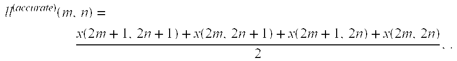
- Where m and n are the indices of the row and column of the coefficient respectively.
- As described in FIG. 18, 19 and 20, according to the step defined in (3.2), we first apply the X-direction step

- For each input row x(k,•).
- Under
assumption 1 mentioned above, we can write s(k,n) as
- Where e is a random variable with a probability distribution function (P.D.F.) p(•) defined by
- Therefore,

- We then apply the Y-direction transform by

- As in (3.5) we can represent s(2m+1,n) and s(2m,n) by:

- Now we can write:
-
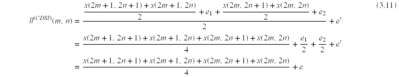
- Where e 1, e2, e′ are independent (
assumption 2 above) random variables with
- Therefore,

- Thus,

- e represents the approximation error of the LL-subband coefficients, results from one 2D transform step. The error relates to the accurate floating-point computation.
- This was a description of a single 2D-transform step assuming that the input coefficients are without any error. Now we wish to evaluate the error accumulated after several steps.
- At an arbitrary step i≧0, we can assume that an input coefficient can be written as:
- x i(k,l)=x i (accurte)(k,l)+e i,
- Where x i (accurate)(k,l) is the accurate value achieved by floating-point computation for all the previous steps, i.e., a step defined by
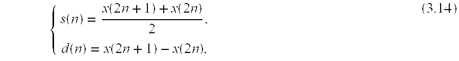
- Instead of the integer-to-integer computation in (3.2). Observe that if x i (accurate)(k,l) is the i-th resolution image coefficient, using (3.14) as the 1D Wavelet step, then

- Where ll i−1 (accurate)(k,l) is the normalized (L2−norm) LL-subband coefficient resulting from the i-
th 2D transform step using (3.1) as the 1D Wavelet step (see Figure ). ei is the difference between xi(k,l) and xi (accurate)(k,l) (I.e., the approximation error of the integer computation made until now). E.g. e0=0(x0(k,l) is an original image pixel), while e1 is a random number with expectation
- And variance

- (see (3.12)).
- Using (3.11), we get:
-

- Where e i+1 is defined by

- And corresponds to LL i subband.
- Consequently
- E(e i+1)=E(e i)+E(e),
-

- Observe that

- As a result, we can write recursive formulas for the error expectation and variance after i steps.

- The explicit solutions to these formulas are

- By replacing

- Thus, the approximation to ll i (accurate)(m,n) is
- 2i+1 ll i (CDSI)(m,n)=ll i (accurate)(m,n)+2i+1 e i+1.
- The approximation error expectation is

- The approximation error variance and standard deviation are
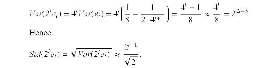
- Let us now evaluate the approximation error of the 3 other subbands:

- Where
-
e i k 1≦k≦4 are identical to the random variable whose expectation and variance are given in (3.17).
- e′ and e″ are identical to the random variable whose expectation and variance are given in (3.7).
- Thus,
- E(e i LH)=0,
-

- The approximation to lh i (accurate)(m,n) is
- 2i lh i (CDSI)(m,n)=lh i (accurate)(m,n)+2i e i LH.
- The approximation error variance and standard deviation are:

- Therefore
- Std(2i e i LH)={square root}{square root over (Var(2i e i LH))}≈{square root}{square root over (4i−1)}=2i−1.
- A similar approximation error estimation, it can be done with the HL-subband and the HH-subband.
- The approximation error evaluation results are summarized in the following table where the error is the difference between the normalized (in L 2-norm) coefficients according to [CDSI] reversible transform and the “mathematical” transform (defined in (3.1)).
TABLE 2 Normalized (in L2 − norm) approximation errors of the Wavelet coefficients at resolution i ≧ 0 (i = 0 is the highest resolution) using the (CDSI) reversible Haar transform. Expectation Variance Std LLi − error −(i + 1)2i 
0.707 · 2i LHi − error 0 
0.5 · 2i HLi − error 

0.433 · 2i HHi − error 0 
0.354 · 2i - Assuming a low-bit rate transmission where only the coefficients whose absolute value belongs to the range [2 b,2b+1) are encoded, for every resolution i, where i is greater than b(less or more). It must be noted that the large error implies a significant loss of coding efficiency.
- Instead, we propose a new family of reversible transforms. The proposed family of integer wavelet transforms has all three properties:
- 1. Reversibility
- 2. De-correlation
- 3. Scaling-i.e. improved approximation of the “mathematical” transform.
- Our 2D transform step is separable also, but the one-dimensional transform step, which the 2D transform is based on, is different for the X-direction (step 1901), the Y-direction step applied on the low output of the X-direction step (step 2001) and the Y-direction step applied on the high output of the X-direction step (step 2002) as described in FIG. 18, 19 and 20.
- The full 2D Wavelet transform is applied by using the 2D Wavelet transform step iteratively in the classic Mallat decomposition of the image (FIG. 21) ([M] 7.7). As mentioned before, the Wavelet coefficients in our proposed transform are all scaled, i.e. normalized in L 2-norm as the Wavelet coefficients computed in the accurate “mathematical” transform.
- In order to achieve the third property (improved approximation of the “mathematical” transform), we define an extra matrix we call the “Half bit-matrix” which enables the reversibility of the High Y-transform step (step 2002). The elements that belong to this matrix are bits, such that each bit corresponds to an HH-subband coefficient in the following interpretation. Let us describe this by the following example.
- Supposing
- s(n)=7, d (1)(n)=9
- Are a coefficient pair results from a reversible de-correlated 1D-wavelet step

- Now, d (1)(n) has to be multiplied by

- In order to be scaled.
- The binary form of d (1)(n)=9 is
- d (1)(n)=10012.
- If we now divide d (1)(n) by 2 in a floating-point computation we get

- Let us call the bit, which located on the write-side of the floating point the “Half Bit”. Observe that the Half Bit of d FP(n) is the LSB of d(1)(n). Therefore, an equivalent way to do this in an integer computation without loosing the Half-Bit is to calculate first the LSB of d(1)(n) by
- HalfBit(n)=d (1)(n)mod2=9mod2=1,
- Then to shift-write d (1)(n) by
- d(n)=d (1)(n)>>1=1001>>1=100.
- By saving d(n) and HalfBit(n) we can restore back d (1)(n).
- In the proposed transform, this Half-bit is needed in the HH-subband coefficient computation. Therefore in our wavelet decomposition for every HH-subband coefficient (in all scales) there is a corresponding bit, which is the coefficient's Half-bit.
- The Half bit matrix is hidden in the HH-subband in the description of FIG. 18, 19 and 20. It is described explicitly in the specification of the transform as much in the coding algorithm.
- We now present our integer-to-integer versions of the Haar transform and the CDF ( 1,3) transform for the 2-dimensional case.
- 3.1 Reversible Haar and (CDF) ( 1,3) Transforms
- 3.1.1Haar Transform
- With respect to FIG. 19:
- 3.1.1.1 Step 1901: X-direction
- Forward Step

- Inverse Step

- With respect to FIG. 20:
- 3.1.1.2 Step 2001: Y-direction—Low Forward Step

- Remarks:
- 1. s(n) is a scaled LL-subband coefficient.
- 2. s(n) and d (1)(n) are de-correlated and a reversible couple (can be transformed back to x(2n) and x(2n+1)), but d(1)(n) is not scaled (it is half its “real value”). Thus, d(1)(n) is multiplied by 2. Nevertheless, the LSB of the LH-subband coefficient d(n) is known to be 0 and not encoded.
- Inverse Step

- With respect to FIG. 20:
- 3.1.1.3 Step 2002: Y-direction—High Forward Step

- Remark: d (1)(n) and s(n) are de-correlated and reversible couples, but d(1)(n) is not scaled (It is twice its “real value”). Therefore, d(1)(n) is divided by 2. By doing that, we lose its least significant bit, which cannot be restored. To solve this problem, as explained before, we save this bit as the “Half-Bit”. Giving this name to that coefficient means that its weight is

- In the “real mathematical scale”, and it is the least significant (from the approximation point of view).
- Inverse Step

- 3.1.2 CDF (1,3) Transform
- 3.1.2.1 Step 1901: X-direction
- With respect to FIG. 19:
- Forward Step

- Inverse Step

- With respect to FIG. 20:
- 3.1.2.2 Step 2001: Y-direction—Low Forward Step

- Remark: See remarks for (3.22).
- Inverse Step

- With respect to FIG. 20:
- 3.1.2.3 Step 2002: Y-direction—High Forward Step
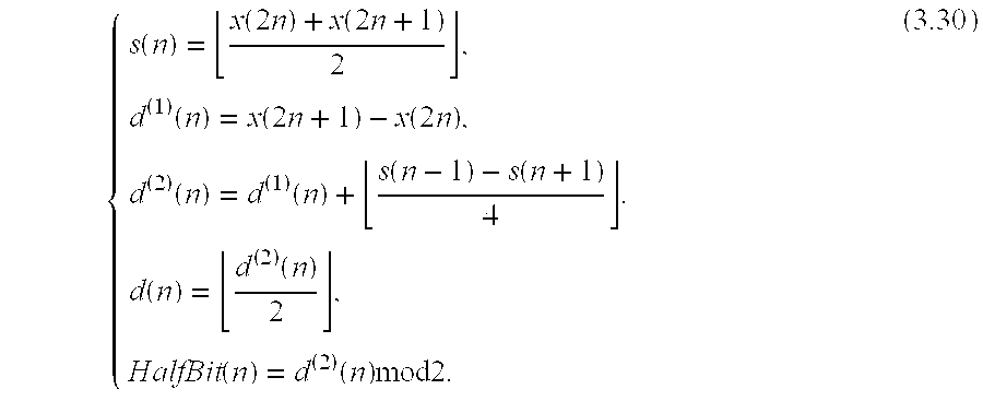
- Inverse Step

- We now compute the approximation error probabilities of our method, and show that it is significantly smaller. We start with the LL-subband error. Assuming e i is the approximation error of the LL-subband in the i-th resolution (FIG. 21), the LL-subband coefficient in the i-th resolution can be written as:

- Where
- ll i (new)(m,n) is the new transform LL-subband coefficient (i-th resolution).
- e i−1 k for 1≦k≦4, are identical random variable representing the error from the previous level.
- e′ and e″ are random variables with P.D.F. defined in (3.6).
- X i (acc.)(m,n) is the i-th resolution image coefficient using (3.1) as the 1D Wavelet step.
- ll i (acc.)(m,n) is the normalized (L2-norm) LL-subband coefficient resulting from the i-
th 2D transform step using (3.1) as the 1D Wavelet step (see FIG. 21).
- Consequently

- By knowing that e −1=0 we get

- Now we can easily evaluate the approximation error of the 3 other subbands:
- lhi (new)(m,n)

- Where
- lh i (new)(m,n) is the new transform LH-subband coefficient (i-th resolution).
- lh i (accurate)(m,n) is the normalized (L2-norm) LH-subband coefficient resulting from the i-
th 2D transform step using (3.1) as the 1D Wavelet step (see FIG. 21). - e′″ is a random variable with P.D.F. defined in (3.6).

- all other symbols are defined like in (3.32).
- Hence

- Similar estimation can be done for the HL and the HH subbands.
- The error estimation (for all subbands) are summarized in the following table where the error is the difference between the normalized (in L 2-norm) coefficients according to our new reversible transform and the “mathematical” transform (defined in (3.1)).
TABLE 3 Normalized (in L2 − norm) approximation errors of the Wavelet coefficients at resolution i ≧ 0 (i = 0 is the highest resolution) using the proposed reversible Haar transform. The result for the LL-subband is valid for the proposed reversible (1,3) transform also. Expecation Variance Std LLi − error 


LHi − error 


HLi − error 


HHi − error 


- The meaning of this result is that in a low bit-rate, where only large coefficients are encoded, this error is negligible.
- 4. Imaging Protocol and Distributed Database
- Dividing the data into tiles and bit-planes
- For the purpose of efficient rendering the coefficients may be sub-divided into tiles. The tiles of this invention differ from previous art as shown in FIG. 12. As in the lossy algorithm, here also the subband tiles are further decomposed to subband data blocks. Each data block of lossless subband tile (FIG. 12) will have a 4D coordinate
- (t_x, t_y, t_resolution,t_bitPlane)
- Where 0≦t_bitPlane≦maxBitPlane(t_resolution).
- Each data block contains the following data in encoded format:
- 1. For t —bitPlane≧2:
- a. A list of the indices of all subband coefficients whose absolute value is in the range [2 t — bitPlane−1, 2t — bitPlane).
- b. The sign of all the coefficients of a.
- c. For t_bitPlane>2, an additional precision bit for any coefficient that belongs to the current bit plane or any higher bit plane.
- 2. For t_bitPlane=1, which we call the “least significant bit plane”:
- a. A list of the indices of HL-subband and HH-subband coefficients whose absolute value belongs to the set {−1,0,1}.
- b. A “zero flag” for each coefficient of a, which indicates if the coefficient is equal to zero or not.
- c. The sign of all the coefficients of a, whose “zero flag” is false.
- d. The LSB of the HL-subband and HH-subband coefficients that belong to higher bit plane.
- Remark:
- Since the LH-subband contains only even coefficients, their LSB must be zero and is not coded.
- 3. For t_bitPlane=0, which we call the “half bit plane”, a matrix of

- Bits associated with HH-subband coefficients as their last “half bit” (See (3.24) or (3.30)).
- 5. The Progressive Subband Coding Algorithm
- 5.1 The Encoding Algorithm
- The encoding algorithm of the present invention is performed at the
server 120. In the present imaging system this rather time consuming task is performed locally in near real-time for a ROI, and not on the full image. The encoding algorithm is described for images with a single color component, such as grayscale images, but of course may also be applied to images with multiple color components. The straightforward generalization for an arbitrary number of components will be explained later. - The lossless algorithm receive as input the following parameters:
TABLE 4 Lossless Encoding Algorithm Input Parameters Variable Meaning coef Matrix of subband coefficients, containing 
HalfBit Matrix of bits containing 
bits. - The coding strategy is similar in some sense to that described in A. Said and W. Pearlman, “A new, fast and efficient image codec based on set partitioning”, IEEE Trans. Circuits and Systems for video Tech., Vol. 6, No. 3, pp. 243-250, 1996, but the preferred embodiment uses no “Zero Tree” data. For all the data blocks with t_bitplane ≧2, we use the lossy encoding algorithm described in previous art with the parameters:
- coef:=coef (The lossy parameter coef initialized with the lossless parameter coef)
- equalBinSize:=True
- ε c:=2
- Remark: The lossy algorithm encodes all the bit-plane information for t_bitplane≧2.
- For t_bitPlane≦1, i.e. the least significant bit plane (of the lossless algorithm) and the half bit plane, we use a different algorithm described in 5.1.3.
- 5.1.1 Encoding Algorithm Initialization
- The lossless encoding algorithm initialization is the same as the lossy algorithm of § 4.1.1 in the above-cited Ser. No. 09/386,264, which disclosure is incorporated herein by reference. In order to initialize the encoding algorithm, the following procedure is performed:
- 1. Assign to each coefficient coef (x,y) its bit plane b(x,y) such that:
- |coef(x,y)|∈[
ε c2b,εc2b+1) - 2. Compute the maximum bit plane over all such coefficients:

- 3. Write the value of maxBitPlane(tile) using one byte as the header of the data block:
- (t_x,t_y,t_resolution, maxBitPlane(t_resolution))
- 4. Initialize all the coefficients as members of their corresponding Type 16 group.
- 5. Initialize a list of significant coefficients to be empty.
- 6. Initialize a coefficient approximation matrix coef as zero.
- 5.1.2 The Outer Loop
- The outer loop of the encoding algorithm scans the bit planes from b=maxBitPlane(tile) to b=0. The output of each such bit plane scan is the subband data block. Since the last stage of the encoding algorithm is arithmetic encoding of given symbols, at the beginning of each scan the arithmetic encoding output module is redirected to the storage area allocated for the particular data block. Once the bit plane scan is finished and the data block has been encoded, the output stream is closed and the bit plane b is decremented. After the outer loop is finished the following stages are performed:
- 1. Least significant bit plane is encoded (t_bitPlane= 1).
- 2. Half bit plane is encoded (t_bitPlane=0).
- The output of the least significant bit plane scan is the data block (FIG. 14):
- (t_x, t_y, t_resolution, t_bitPlane=1).
- The half bit plane data block is:
- (t_x, t_y, t_resolution, t_bitPlane=0).
- 5.1.3 Bit-plane Scan
- For t_bitPlane≧2, the framework of the bit plane scan is described in FIG. 24, while the pseudo code is given in the above-cited Ser. No. 09/386,264, which disclosure is incorporated herein by reference. The scan, for a given level b (b≧2), encodes all of the coefficients'data corresponding to the absolute value interval [2 b−1,2b).
- Remark: The encoder method isLastBitPlane( ) is associated to the t_bitPlane=2. For the least significant bit plane, a pseudo code is described in FIG. 15, while a flow chart is described in FIG. 22.
- Explanations to the least significant bit encoding algorithm:
- 1. The coefficients scanning procedure, i.e. moreCoef( ) procedure in FIG. 15 or “More coefficients?” in FIG. 22 includes all the coefficients belong to the HH and the HL-subband (FIG. 14). The LH-subband is skipped, since the least significant bit of each coefficient in it is zero (see
remark 2 for (3.22)). - 2. The procedure isCoefReporeted( ) (“Is coefficient reported?” in the flow chart) returns false if the coefficient is one of {−1, 0,1}, i.e. in all higher bit plane scans it was insignificant, otherwise it returns true.
- 3. The procedure isCoefExactZero( ) (“Coefficient is zero?” in the flow chart) returns true iff the coefficient is zero.
- 4. The procedure getCoefSign( ) returns the coefficient's sign.
- For the half bit plane, a pseudo code is described in FIG. 16.
- 5.2 The Decoding Algorithm
- Obviously, this algorithm is a reversed step of the encoding algorithm of section 5.1, performed in the
server 120. Theclient computer 110 during the progressive rendering operation performs the decoding algorithm. Similar to the encoding algorithm, the decoding algorithm is described for an image with one component (such as a grayscale image), but of course could also be used with an image with more than one component. The input parameters to the lossless algorithm are given below:TABLE 5 Lossless decoding algorithm input parameters Variable Meaning coef Empty matrix of subband coefficients to be filled by the decoding algorithm. HalfBit Matrix of bits containing 
bits. - For all the data blocks with t_bitplane≧2, a “lossy” decoding algorithm is utilized. The input parameters for the lossy algorithm are:
- coef:=coef
- equalBinSize:=True
- ε c:=2
- 5.2.1 Decoding Algorithm Initialization
- 1. Assign to each coefficient Coef (x,y) the value zero.
- 2. Assign to each bit belongs to the HalfBit matrix the value zero.
- 3. Initialize all the coefficients as members of their corresponding Type 16 group.
- 4. Initialize the list of significant coefficients to be empty.
- 5. If the “first” data block
- (t_x,t_y,t_resolution, maxBitPlane(t_resolution))
- Is available at the client, read the first byte, which is the value of maxBitPlane (tile).
- 5.2.2 The Outer Loop
- Upon the completion of the outer loop in 5.1.2 the following stages are preformed:
- 1. The decoding algorithm scans the least significant bit plane. The input to this stage is encoded data block (t_x, t_y, t_resolution, LeastSiginificant_bitPlane).
- 2. The decoding algorithm scans the half bit plane. The input to this stage is encoded data block (t_x, t_y, t_resolution, Half_bitPlane).
- 5.2.3 Bit Plane Scan
- The preferred embodiment follows the lossy prior art of the above-cited Ser. No. 09/386,264, which disclosure is incorporated herein by reference, for t_bitPlane≧2. The scan, for a given level b, decodes all of the coefficients' data corresponding to the absolute value interval [ε2 b,ε2b+1). Pseudo codes of the least significant bit plane scan and half bit plane scan are described in FIG. 16.
- Explanations to the pseudo code:
- 1. The decoder's method morecoef( ) scans all the coefficients in the HH, HL and LH subband. But, since the LH-subband is skipped in the encoding algorithm, we don't call to decodeSymbol( ) for its coefficients. Instead of this, we update their least significant bit as zero.
- 2. Recall that LH-subband coefficients that have not been reported until the least significant bit-plane must be zero since they are known to be even.
- 6. Client Workflow
- With reference to FIG. 4, we describe the workflow at the
client unit 110. Any new ROI generated by the user's action such as a zoom-in, a scroll, or a luminance tuning invokes in step 401 a call from the GUI interface to the client imaging module with the new ROI view parameters. The client imaging module then computes instep 402 which data blocks are required for the rendering of the ROI and checks if these data blocks are available in the client cache. If not, their coordinate is added to a request list ordered according to some progressive mode. The request list is then encoded instep 403 and sent to the server. The server responds to the request by sending back to the client a stream of data blocks, in the order in which they were requested. Instep 404 the client inserts them to their appropriate location in the distributed database. At various points intime step 405, a rendering of the ROI, is invoked. Naturally, the rendering operation is progressive and is able to use only the currently available data in the client's database. - 6.1 Step 401: Receiving the ROI Parameters
- The imaging module on the
client computer 120 receives from the GUI interface module view parameters detailed in Table 5. These parameters are used to generate a request list for the ROI. The same parameters are used to render the ROI.TABLE 5 Variable Meaning worldPolygon A 2D polygon in the original image coordinate system scale The view resolution. 0 < scale < 1 implies a low view resolution, scale = 1 original resolution and scale > 1 a higher than original view resolution deviceDepth A number in the set {8, 16, 24} representing the depth of the output device (screen, printer) viewQuality A quality factor in the range [1,7] where 1 implies very low quality and 7 implies lossless quality luminanceMap If active: a curve defining a mapping of medical images with more than 8 bits (typically 10, 12, 16 bits) per grayscale values to an 8 bit screen progressiveMo One of: Progressive By Accuracy, Progressive By Resolution, Progressive by Spatial Order - The basic parameters of a ROI are worldPolygon and scale which determine uniquely the ROI view. If the ROI is to be rendered onto a viewing device with limited resolution, then a worldPolygon containing a large portion of the image will be coupled by a small scale. In the case where the rendering is done by a printer, the ROI could be a strip of a proof resolution of the original image that has arrived from the
server computer 120. This strip is rendered in parallel to the transmission, such that the printing process will terminate with the end of transmission. The other view parameters determine the way in which the view will be rendered. The parameters deviceDepth and viewQuality determine the quality of the rendering operation. In cases the viewing device is of low resolution or the user sets the quality parameter to a lower quality, the transfer size can be reduced significantly. - The parameter luminanceMap is typically used in medical imaging for grayscale images that are of higher resolution than the viewing device. Typically, screens display grayscale images using 8 bits, while medical images sometimes represent each pixel using 16 bits. Thus, it is necessary to map the bigger pixel range to the smaller range of [0,255].
- Lastly, the parameter progressiveMode determines the order in which data blocks should be transmitted from the
server 120. The “Progressive By Accuracy” mode is the best mode for viewing in low bandwidth environments. “Progressive By Resolution” mode is easier to implement since it does not require the more sophisticated accuracy (bit plane) management and therefore is commonly found in other systems. The superiority of the “progressive by accuracy” mode can be mathematically proven by showing the superiority of “non-linear approximation” over “linear approximation” for the class of real-life images. See, e.g., R. A. DeVore, “Nonlinear approximation”, Acta Numerica, pp. 51-150, 1998. - The “Progressive by Spatial Order” mode is designed, for example, for a “print on demand” feature where the ROI is actually a low resolution “proof print” of a high resolution graphic art work. In this mode the image data is ordered and received in a top to bottom order, such that printing can be done in parallel to the transmission.
- However, since lossless compression is mostly required in medical images transmission, where typically more than 8 bits images are used, we amplify our discussion on the curve (luminanceMap hereinabove) which defines the mapping from the original image gray scale range (typically 10,12,16 bits) to an 8-bit screen. Further more, in medical images viewing, regardless of the original image depth, mapping is required in order to control the brightness and contrast of the image.
- 6.1.1 Luminance Mapping
- Mapping from original image depth (e.g. 10,12,16 bits ) to screen depth (typically 8-bits), is defined by a monotonic function (FIG. 17):
- ƒ:[0,2original — image — depth−1]→[0,2screen — depth−1]. (6.1)
- The curve influences not only the mapping, i.e. the drawing to the screen, but also the request from the server. To understand that, let us concentrate in the maximal gradient of the curve (FIG. 17). In a lossy mode, the request is created such that the image approximation in the client side is close enough to the original image, i.e., the RMS (Root Mean Square Error) is visually negligible. When a curve (mapping function) is applied, the RMS can be increased or reduced. The maximal RMS increasing factor depends on the maximal gradient of the curve as follows:

- Where
- I is the original image
- Î is the approximated image
- ƒ is the mapping function

- max (ƒ′) is the maximal gradient of the curve.
- We consider the worst case of the RMS increasing factor i.e.:
- RMS_increasing_factor=Maximal_gradient=max(ƒ′)
- If the RMS increasing factor is greater than 1, it means that the “new RMS” may be greater than we consider as visually negligible error. Thus, the request list should be increase (more bit-planes should be requested from the server) in order to improve the approximation accuracy. Conversely, if the RMS increasing factor is smaller than 1, the request listing can be reduced. The exact specification of this is given in the following section.
- 6.2 Step 402: Creating the Request List
- In
step 402 using the ROI view parameters, the client imaging module at theclient computer 110 calculates data blocks request list ordered according to the progressiveMode. Given the parameters worldPolygon and Scale, it may be determined which subband tiles in the “frequency domain” participate in the reconstruction of the ROI in the “time domain”. These tiles contain all the coefficients that are required for an “Inverse Subband/Wavelet Transform” (IWT) step that produces the ROI. First, the parameter dyadicResolution (ROI) is computed, which is the lowest possible dyadic resolution higher than the resolution of the ROI. Any subband tiles of a higher resolution than dyadicResolution (ROI) do not participate in the rendering operation. Their associated data blocks are therefore not requested, since they are visually insignificant for the rendering of the ROI. If scale≧1, then the highest resolution subband tiles are required. If scale≦21−numberOfResolutions then only the lowest resolution tile is required. For any other value of scale we perform the mapping described below in Table 6.TABLE 6 scale highestSubbandResolution scale ≦ 21 − numberOfResolutions 1 21 −numberOfResolutions > scale ≦1 numberOfResolutions − └− log2 (scale)┘ scale > 1 numberOfResolutions - Once it has been determined which subband tiles participate in the rendering of the ROI, it is necessary to find which of their data blocks are visually significant and in what order they should be requested. Using well known rate/distortion rules from the field of image coding (such as is described in S. Mallat and F. Falzon, “Understanding image transform codes”, Proc. SPIE Aerospace Conf., 1997), it is not too difficult to determine an optimal order in which the data blocks should be ordered by the client imaging module (and thus delivered by the server 120). This optimal order is described in steps 301-310 of FIG. 3 for the “Progressive By Accuracy” mode. The underlying mathematical principal behind this approach is “Non-Linear Approximation”.
- First, the subband coefficients with largest absolute values are requested since they represent the most visually significant data such as strong edges in the image. Notice that high resolution coefficients with large absolute value are requested before low resolution coefficients with smaller absolute value. Within each given layer of precision (bit plane) the order of request is according to resolution; low resolution coefficients are requested first and the coefficients of highestSubbandResolution are requested last.
- The main difficulty of this step is this: Assume a subband tile is required for the rendering of the ROI. This means that t_resolution≦dyadicResolution (ROI) and the tile is required in the IWT procedure that reconstructs the ROI. It must be understood which of the data blocks associated with the subband tile represent visually insignificant data and thus should not be requested. Sending all of the associated data blocks will not affect the quality of the progressive rendering. However, in many cases transmitting the “tail” of data blocks associated with high precision is unnecessary since it will be visually insignificant. In such a case, the user will see that the transmission of the ROI from the
server 120 is still in progress, yet the progressive rendering of the ROI seems to no longer to change the displayed image. - Additionally, the influence of the luminance mapping on the accuracy level of the requested data block as described below. Supposing for some t_x,t_y and t_resolution, the set
- {(t_x,t_y,t_resolution, t_bitplane)|T≦t_bitPlane≦maxPlaneBit(t_resolution)}
- Is requested where T is the minimal bit plane required to the current view. Here, where the luminance mapping is taken in account, the value of T might be increased or decreased.
- The number of bit planes reduced (added) from the request list is

- i.e., for those t_x,t_y and t_resolution mentioned before, the following set is requested:
- {(t_x,t_y,t_resolution, t_bitPlane)|T′≦t_bitPlane≦maxPlaneBit (t_resolution)}
- Where

- Examples:
- 1. Given
- Image depth of 12-bit
- Screen depth of 8-bit
- Linear luminance mapping, I.e.,

- The number of bit planes reduced from the request list is:

- 2. Given a luminance mapping with Maximal gradient=2
- The number of bit planes reduced from the request list is:

- Thus one bit plane is added to the original set.
- 6.3 Step 403: Encoding the Request List
- The client imaging module in the
client computer 110 encodes the request list into a request stream that is sent to theserver computer 120 via the communication network 130 (FIG. 1). The request list encoding algorithm is a simple rectangle-based procedure. The heuristics of the algorithm is that the requested data block usually can be grouped into data block rectangles. From the request list of data blocks indexed by the encoding algorithm computes structures of the type - {(t_x,t_y,t_resolution, t_bitPlane),nx,ny}, n x,ny≧1 (1.3)
- Each such structure represents the n xxny data blocks
- {(t_x+i,t_y+j,t_resolution,t_bitplane)}, 0≦i<nx, 0≦j<ny
- The encoding algorithm attempts to create the shortest possible list of structures, collecting the data blocks to the largest possible rectangles can do this. It is important to note that the algorithm ensures the order of data blocks in the request list is not changed, since the
server 120 will respond to the request stream by transmitting data blocks in the order in which they were requested. A good example of when this works well is when a user zooms in into a ROI at a high resolution that was never viewed before. In such a case the request list might be composed of hundreds of requested data blocks, but they will be collected to one (x, y) rectangle for each pair (t_resolution, t_bitPlane). - 6.4 Step 404: Receiving the Data Blocks
- The
client computer 110 upon receiving from theserver computer 120 an encoded stream containing data blocks, decodes the stream and inserts the data blocks into their appropriate location in the distributed database using their ID as a key. The simple decoding algorithm performed here is a reversed step of the encoding infra. Since theclient 110 is aware of the order of the data blocks in the encoded stream, only the size of each data block need be reported along with the actual data. In case theserver 120 informs of an empty data block, the receiving module marks the appropriate slot in the database as existing but empty. - Recall that the subband tile associated with each data block is denoted by the first three coordinates of the four coordinates of a data block (t_x,t_y,t_resolution). From the subband tile's coordinates the dimensions are calculated of the area of visual significance; that is, the portion of the ROI that is affected by the subband tile. Assume that each subband tile is of length tileLength and that the wavelet basis used has a maximal filter size maxFilterSize, then defining hFilterSize :=┌maxFilterSize/2┐ and factor:=numberOfResolutions—
t_resolution+ 1, we have that the dimensions of the affected region of the ROI (in the original image's coordinate system) are - [t_x×tileLengthfactor-hFilterSizefactor,(t_x+1)×tileLengthfactor+hFilterSizefactor]×
- [t_y×tileLengthfactor-hFilterSizefactor, (t_y+1)×tileLengthfactor+hFilterSizefactor]
- These dimensions are merged into the next rendering operation's region. The rendering region is used to efficiently render only the updated portion of the ROI.
- 6.5 Progressive Rendering
- During the transmission of ROI data from the server to the client, the client performs rendering operations of the ROI. To ensure that these rendering tasks do not interrupt the transfer, the client runs two program threads: communications and rendering. The rendering thread runs in the background and draws into a pre-allocated “off-screen” buffer. Only then does the client use device and system dependant tools to output the visual information from the “off-screen” to the rendering device such as the screen or printer.
- The rendering algorithm performs reconstruction of the ROI at the highest possible quality based on the available data at the client. That is, data that was previously cached or data that “just” arrived from the server. For efficiency, the progressive rendering is performed only for the portion of the ROI that is affected by newly arrived data. Specifically, data that arrived after the previous rendering task began. This “updated region” is obtained using the method of
step 404 described in §6.4. - The parameters of the rendering algorithm are composed of two sets:
- 1. The ROI parameters described in Table 3.
- 2. The parameters transmitted from the server explained in Table 5, with the exception of the jumpsize parameter, which is a “server only” parameter.
- The rendering algorithm computes pixels at the dyadic resolution dyadicRresolution(ROI). Recall that this is the lowest possible dyadic resolution that is higher than the resolution of the ROI. The obtained image is then resized to the correct resolution. Using a tiling of the multiresolution representation of the ROI, the steps of the algorithm are performed on a tile by tile basis as described in FIG. 11. Since the tiles' length are tileLength, which is typically chosen as 64, the rendering algorithm is memory efficient.
- 6.5.1 The Rendering Rate
- As ROI data is transmitted to the
client 110, the rendering algorithm is performed at certain time intervals of a few seconds. At each point in time, only one rendering task is performed for any given displayed image. To ensure that progressive rendering does not become a bottleneck, two rates are measured: the data block transfer rate and the ROI rendering speed. If it predicted that the transfer will be finished before a rendering task, a small delay is inserted, such that rendering will be performed after all the data arrives. Therefore, in a slow network scenario (as the Internet often is), for almost the entire progressive rendering tasks, no delay is inserted. With the arrival of every few kilobytes of data, containing the information of a few data blocks, a rendering task visualizes the ROI at the best possible quality. In such a case the user is aware that the bottleneck of the ROI rendering is the slow network and has the option to accept the current rendering as a good enough approximation of the image and not wait for all the data to arrive. - 6.5.2 Memory Constraint Subband Data Structure
- This data-structure is required to efficiently store subband coefficients, in memory, during the rendering algorithm. This is required since the coefficients are represented in long integer (lossless coding mode) or floating-point (lossy coding mode) precision which typically require more memory than pixel representation (1 byte). In lossy mode, the coefficients at the
client side 110 are represented using floating-point representation, even if they were computed at theserver side 120 using an integer implementation. This will minimize round-off errors. - At the beginning of the rendering algorithm, coefficient and pixel memory strips are initialized. dyadicWidth (ROI) may be denoted as the width of the projection of the ROI onto the resolution dyadicResolution (ROI). For each component and
resolution 1<j≦dyadic Re solution (ROI), four subband strips are allocated for the four types of subband coefficients: hl,lh,hh and HalBit. The coefficient strips are allocated with dimensions
- For each component and
resolution 1≦j<dyadicResolution a pixel strip is allocated with dimensions
- Beginning with the
lowest resolution 1, the algorithm proceeds with a recursive multiresolution march from the top of the ROI to bottom (y direction. Referring to FIGS. 10 and 11, instep 1101, the multiresolution strips are filled with sub-tiles of coefficients 1050 decoded from the database or read from the memory cache. From the coefficients we obtain multiresolution pixels 1051 using an inverse subband transform step 1102 (shown in further detail in FIG. 10). Each time a tile of pixels at resolutions j<dyadicResolution (ROI) is reconstructed, it is written into the pixel strip at the resolution j. Each time a tile of pixels at the highest resolution dyadicResolution (ROI) is reconstructed, it is fed into the inverse color transform and resizingsteps - 6.5.3 Step 1101: Decoding and Memory Caching
- The subband coefficients data structure described previously in section 6.5.2 is filled on a tile basis. Each such subband tile is obtained by decoding the corresponding data blocks stored in the database or reading from the memory cache. The memory cache is used to store coefficients in a simple encoded format. The motivation is this: the decoding algorithm described previously in section 5.2 is computationally intensive and thus should be avoided whenever possible. To this end the rendering module uses a
memory cache 111 where subband coefficient are stored in very simple encoded format which decodes very fast. For each required subband tile, the following extraction procedure is performed, described in FIG. 25, beginning atstep 2501. Instep 2502, if no data blocks are available in the database for the subband tile, its coefficients are set to zero (step 2503). Instep 2504, if the tile's memory cache storage is updated, namely it stores coefficients in the same precision as in the database, then the coefficients can be efficiently read from there (step 2505). Instep 2506, the last possibility is that the database holds the subband tile in higher precision. Then, the tile is decoded down to the lowest available bit plane using the algorithm previously described in section 5.2 and the cached representation is replaced with a representation of this higher precision information. - 6.5.4 Step 1102: Inverse Lossless Wavelet Transform
- This is an inverse step to step 603 performed in the server (see 7.1.5). Following FIG. 21 we see that four “extended” subband coefficient sub-tiles of length tileLength/2+maxFilterSize at the resolution i are read from the coefficient strips data structure and transformed to a tile of pixels at the next higher resolution using losslessWaveletdTransformType(i). If i+1<dyadicResolution (ROI), the tile of pixels obtained by this step is inserted into the pixel memory strip at the resolution i+1. If i+1=dyadicResolution (ROI) the tile of pixels is processed by the next step of color transform.
- Remark: Recall from 5.1.1 that the “half bits” are initialized as zeros, therefore the inverse step is well defined even if their “real” value is not available in the client yet.
- 6.5.5 Step 1103: Inverse Color Transform
- This is an inverse step to step 603 performed at the
server 120. It is performed only for tiles of pixels at the resolution highestSubbandResolution. At this stage, all of the pixels of each such tile are in the outputColorSpace and so need to be transformed into a displaying or printing color space. For example, if the original image at theserver 120 is a color image in the color space RGB, the pixels obtained by the previous step of inverse subband transform are in the compression color space YUV. To convert back from YUV to RGB, we use the inverse step described in FIG. 13. If the ROI is at an exact dyadic resolution, then the tile of pixels in the rendering color space is written into the off-screen buffer. Else it is resized in the next step. - 6.5.6 Step 1104: Image Resize
- In case the resolution of the ROI is not an exact dyadic resolution, the image obtained by the previous step must be re-sized to this resolution. This can be accomplished using operating system imaging functionality. In most cases the operating system's implementation is sub-sampling which produces in many cases an aliasing effect which is visually not pleasing. To provide higher visual quality, the imaging system of the present invention may use the method of linear interpolation, for example described in J. Proakis and D. Manolakis, “Digital signal processing”, Prentice Hall, 1996. The output of the interpolation is written to the off-screen buffer. From there it is displayed on the screen using system device dependant methods.
- 6.5.7 Step 1105: Mapping to 8-bit Screen
- When luminanceMap is active mapping to 8-bit screen is performed using the mapping function described in 6.1.1.
- 7. Server Worflow
- With reference to FIG. 5, the operation of the server computer 120 (FIG. 1) will now be described. Initially, an uncompressed digital image is stored in, for example,
storage 122 of theserver computer 120. This uncompressed digital image may be a two-dimensional image, stored with a selected resolution and depth. For example, in the medical field, the uncompressed digital image may be contained in a DICOM file. - Once the
client computer 110 requests to view or print a certain image, the server performs thepreprocessing step 501. This step is a computation done on data read from the original digital image. The results of the computation are stored in theserver cache device 121. After this fast computation a “ready to serve” message is sent from the server to the client containing basic information on the image. - In
step 502, the server receives an encoded stream of requests for data blocks associated with a ROI that needs to be rendered at the client. The server then decodes the request stream and extracts the request list. - In step 503, the server reads from cache or encodes data block associated with low resolution portions of the ROI, using the cached result of the
preprocessing stage 501. - If the ROI is a high-resolution portion of the image, the server, in
step 504, reads from cache or performs a “local” and efficient version of thepreprocessing step 501. Specifically, a local portion of the uncompressed image, associated with the ROI, is read from thestorage 122, processed and encoded. Instep 505, the data that was encoded in steps 503-504 is progressively sent to the client in the order it was requested. - 7.1 Step 501: Preprocessing
- The preprocessing step is now described with respect to FIG. 6. The preprocessing algorithm's goal is to provide the fastest response to the user's request to interact with the image. Once this fast computational step is performed, the server is able to provide efficient “pixel-on-demand” transmission of any client ROI requests that will follow. In most cases the first ROI is a view of the full image at the highest resolution that “fits” the viewing device. The preprocessing algorithm begins with a request for an uncompressed image that has not been processed before or has been processed but the result of this previous computation has been deleted from the cache. As explained, this unique algorithm replaces the possibly simpler procedure of encoding the full image into some progressive format. This latter technique will provide a much slower response to the user's initial request then the technique described below. At the end of the algorithm a “ready to serve ROI of the image” message is sent to the client containing basic information on the image. While some of this information, image dimensions, original color space, resolution etc., is available to the user of the client computer, most of this information is “internal” and required by the client to formulate ROI request lists (§6.2) and progressively render (§6.5). Next we describe in detail the preprocessing algorithm.
- 7.1.1 Preprocessing Parameters
TABLE 7 Variable Meaning losslessMode If true, preprocessing will prepare data that can be used for lossless transmission. subbandTransformType The framework allows the ability to select a different subband transform for each resolution of each image. The technical term is: non-stationary transforms. numberOfResolutions The number of resolutions in the Multiresolution structure calculated for the image. Typically, 
jumpSize A number in the range [0, numberOfResolutions − 1]. The preprocessing stage computes only the top lower part of the image's multiresolution pyramid of the size numberOfResolutions − jumpSize. tileLength Typically = 64. Tradeoff between time and coding performance. nTilesX (j) Number of subband tiles in the x direction at the resolution j nTilesX (j) Number of subband tiles in the y direction at the resolution j inputColorSpace Color space of uncompressed original image. outputColorSpace Transmitted color space used as part of the encoding technique. numberOfComponents Number of components in OutputColorSpace. threshold (c, j) A matrix of values used in lossy compression. The subband coefficients of the component c at the resolution j with absolute value below threshold (c, j) are considered as (visually) insignificant and set to zero. - Given an input image, the parameters described in Table 7 are computed or chosen. These parameters are also written into a header sent to the
client 110 and are used during the progressive rendering step 405 (see section 6.5, described previously). The important parameters to select are: - 1. losslessMode: In this mode, progressive transmission of images takes place until lossless quality is obtained. Choosing this mode requires the preprocessing algorithm to use certain reversible wavelet transforms, and can slow down the algorithm.
- 2. subbandTransformType(j): The (dynamic) selection of wavelet basis (as described, for example, in I. Daubechies, “Ten lectures on wavelets”, Siam, 1992) is crucial to the performance of the imaging system. The selection can be non-stationary, meaning a different transform for each resolution j. The selection is derived from the following considerations:
- a. Coding performance (in a rate/distortion sense): This is obviously required from any decent subband/wavelet transform.
- b. Approximation of ideal low pass: It is favorable to choose a transform such that low resolutions of the image will be of high visual quality (some filters produce poor quality low resolutions even before any compression takes place).
- c. Fast transform implementation: Can the associated fast transform be implemented using lifting steps (as described, for example, by I. Daubechies and W. Sweldens, “Factoring wavelet transforms into lifting steps”, J. Fourier Anal. Appl., Vol. 4, No. 3, pp. 247-269, 1998), using only integer shifts and additions, etc. Some good examples are the Haar and CDF transforms ( 1,3), (2,2)*** described in I. Daubechies, “Ten lectures on wavelets”, Siam, 1992.
- d. Fast low pass implementation: A very important parameter, since together with the parameter jumpSize, it determines almost all of the complexity of the algorithm. For example, the CDF ( 1,3) is in this respect the “optimal” transform with three vanishing moments. Since the dual scaling function is the simple B-spline of
order 1, its low pass is simple averaging. Thus, the sequence of CDF transforms, using the B-spline oforder 1 as the dual scaling function, but with wavelets with increasing number of vanishing moments are in some sense optimal in the present system. They provide a framework for both real time response and good coding efficiency. - e. Lossless mode: IflosslessMode is true we must choose the filters from a subclass of reversible transforms (see, for example, “Wavelet transforms that map integers to integers”, A. Calderbank, I. Daubechies, W. Sweldens, B. L. Yeo, J. Fourier Anal. Appl., 1998).
- f. Low system I/O: If the
network 130 in FIG. 1 connecting between the Image residing on thestorage 122 and theimaging server 120 is slow, the bottleneck of the preprocessing stage (and the whole imaging system for that fact) might be simply the reading of the original image. In such a case a transform may be chosen with a lazy sub-sampling low pass filter that corresponds to efficient selective reading of the input image. Many interpolating subband transforms with increasing number of vanishing moments can be selected to suit this requirement. However, this choice should be avoided whenever possible, since it conflicts with (a) and (b). - g. Image type: If the type of the image is known in advance, an appropriate transform can be chosen to increase coding efficiency. For example: Haar wavelet for graphic images, smoother wavelet for real-life images, etc. In the graphic arts field, there are numerous cases of documents composed of low resolution real-life images and high resolution graphic content. In such a case, a non-stationary sequence of transforms may be chosen: Haar for the high resolutions and a smoother basis starting at the highest resolution of a real-life image part. In case of low system I/O (f), a non-stationary choice of interpolating transforms of different orders is required.
- 3. jumpSize: This parameter controls the tradeoff between fast response to the user's initial request to interact with the image and response times to subsequent ROI requests. When jumpSize is large, the initial response is faster, but each computation of a region of interest with higher resolution than the jump might require processing of a large portion of the original image.
- 4. InputColorSpace: The input color spaces supported in lossless mode are:
- a. Grayscale: For grayscale images
- b. RGB
- 5. outputColorSpace: The following are color spaces which perform well in coding:
- a. Grayscale: For grayscale images
- b. YUV: for viewing color images
- Referring to Table 7 [LP], losslessMode is set to true. Threshold (c,j) is not in use, since in lossless mode, there is no thresholding. The rest of the variables have the same meaning as in the lossy algorithm.
- 7.1.2 Memory Constraint Multiresolution Scan Data Structure
- Most wavelet coding algorithms have not addressed the problem of memory complexity. Usually the authors have assumed there is sufficient memory such that the image can be transformed in memory from the time domain to a wavelet frequency domain representation. It seems the upcoming JPEG2000 will address this issue, as did its predecessor JPEG. The preprocessing algorithm also requires performing subband transforms on large images, although not always on the fall image, and thus requires careful memory management. This means that the memory usage of the algorithm is not of the order of magnitude of the original image, as described in J. M. Shapiro, “An embedded hierarchical image coder using zero-trees of wavelet coefficients”, IEEE Trans. Sig. Proc., Vol. 41, No. 12, pp. 3445-3462, 1993.
- Given an uncompressed image we allocate the following number of memory strips
- numberOfComponents×(numberOfResolutions−jumpSize)
- Of sizes
- [2−(numberOfResolutions−j)imageWidth,3×tileLength/2+maxFilterSize]
- For 1≦j≦numberOfResolutions−jumpSize−1 and
- [image Width,tileLength+2×maxFilterSize]
- For j=numberOfResolutions−jumpSize
- That is, the memory usage is proportional to 2 −jumpSize×imageWidth. Each such strip stores low-pass coefficients in the color space outputColorSpace at various resolutions.
- Referring to FIG. 6, during the preprocessing stage, the resolutions are scanned simultaneously from start to end in the y direction. For each color component and resolution, the corresponding strip stores low-pass coefficients or pixels at that resolution. The core of the preprocessing algorithm are steps 604-607, where tiles of pixels of length tileLength+2×maxFilterSize are read from the memory strips and handled one at a time. In
step 604 the tile is transformed into a tile of length tileLength containing two types of coefficient data: subband coefficients and pixels at a lower resolution. The subband coefficients are processed in steps 605-606 and are stored in the cache. The lower resolution pixels are inserted instep 607 to a lower resolution memory strip. Whenever such a new sub-tile of lower resolution pixels is inserted into a strip, the algorithm's memory management module performs the following check: If the part of the sub-tile exceeds the current virtual boundaries of the strip, the corresponding first lines of the strip are considered unnecessary anymore. Their memory is (virtually) re-allocated for the purpose of storing the sub-tile's new data. - 7.1.3 Step 601: Lossless Color-transform
- This step is uses the conversion formula described in FIG. 13. This step must be performed before
step 602, because the lossless color conversion is non-linear. 7.1.4 Step 602: Lossless Wavelet Low Pass - The motivation for the low pass step is explained in § 6.1.4 in the above-cited Ser. No. 09/386,264, which disclosure is incorporated herein by reference. In a lossless mode there are a few emphasis that are represented here.
- In
step 602, the low pass filters of the transforms subbandTransformType(j), numberOfResolutions−jumpSize<j ≦numberOfResolutions, are used to obtain a low resolution strip at the resolution numberOfResolutions−jumpSize (as can be seen in FIG. 26). Typically, it is required to low pass about 2jumpSize lines of the original image 1010 to produce one line of the low resolution image. The low pass calculation is initiated by a read of tiles of pixels from the memory strips performed instep 604. Whenever there is an attempt to read missing low resolution lines, they are computed by low passing the original image and inserted into the memory strip. The insertion over-writes lines are no longer required, such that the algorithm is memory constrained. In the case where a non-linear color transform took place in theprevious step 601, the results of that transform are low-passed. - In the lossless mode of operation, the jumpSize parameter defines the number of lossless wavelet low pass steps should be done. A single low pass step is the same for Haar and CDF ( 1,3) and defined by the following two stages (taken from (3.20) and (3.22):

- Y-direction: s(n)=x(2n)+x(2n+1).
-
- Namely, in a 2D representation, the low pass step is defined by

- ForjumpSize=1 and jumpSize=2 (other sizes practically are not needed), the server performs these steps efficiently (almost like the lossy algorithm) by a single operation that simulates exactly jumpSize low pass steps defined in (7.1). As noticed from (7.1), the simplicity of the formula makes filters such as Haar and CDF ( 1,3) “optimal” in the respect of low pass efficiency.
- 7.1.5 Step 603: Forward Lossless Wavelet Transform
- In
Step 603 we perform one step of an efficient local lossless wavelet transform (§3), on a tile of pixels at theresolution 1≦j≦numberOfResolutions−jumpSize. The type of transform is determined by the parameter lossless WaveletTransformType(j). As described in FIG. 1, the transform is performed on an “extended” tile of pixels is of length tileLength+2×maxFilterSize (unless we are at the boundaries), read directly from a multi-resolution strip at theresolution j+ 1. The output of the step is a lossless subband tile composed of wavelet coefficients including Half bit coefficients and low resolution coefficients/pixels. The transform step is efficiently implemented in integers as described in §3. - The subband transform of
step 603 outputs three types of data: scaling function (low pass), wavelet (high pass) and Halfbits. The wavelet coefficients are treated instep 604 while the scaling function coefficients are treated instep 605. - Remark: Tiles of pixels which are located on the boundaries sometimes need to be padded by extra rows and/or columns of pixels, such that they will formulate a “full” tile of length tileLength.
- 7.1.6 Step 604: Variable Length Encoding and Storage
- In
step 604, the subband coefficients that are calculated instep 603 are variable length encoded and stored in thecache 121. If maxBitPlane (tile)=0 we do not write any data. Else we loop on the coefficient groups {coef(2×i+x,2×j+y)}x,y=0,1. For each such group we first write the group's variable length length (i,j) using log2(maxBitPlane(tile)) bits. Then for each coefficient in the group we write length (i,j)+1 bits representing the coefficient's value. The least significant bit represents the coefficient's sign: if it is 1 then the variable length encoded coefficient is assumed to be negative. The HalfBit subband coefficients are written in one-bit per coefficient. - 7.1.7 Step 605: Copying Low Pass Coefficients into the Multiresolution Strip Structure
- In step 503, unless losslessMode is true, the subband coefficients calculated in
step 604 are quantized. This procedure is performed at this time for the following reason: It is required that the coefficients computed in the previous step will be stored in thecache 121. To avoid writing huge amounts of data to the cache, some compression is required. Thus, the quantization step serves as a preparation step for the next variable length encoding step. It is important to point out that the quantization step has no effect on compression results. Namely, the quantization step is synchronized with the encoding algorithm such that the results of the encoding algorithm of quantized and non-quantized coefficients are identical. - A tile of an image component c at the resolution j is quantized using the given threshold threshold (c,j): for each coefficients x, the quantized value is └x/threshold(c,j)┘. It is advantageous to choose the parameters threshold (c,j) to be dyadic such that the quantization can be implemented using integer shifts. The quantization procedure performed on a subband tile is as follows:
- 1. Initialize maxBitPlane(tile)=0.
- 2. Loop over each group of four coefficients {coef(2×i+x,2×j+y)} x,y=0,1. For each such group initialize a variable length parameter length (i,j)=0.
- 3. Quantize each coefficient in the group coef (2×i+x,2×j+y) using the appropriate threshold.
- 4. For each coefficient, update length (i,j) by the bit plane b of the coefficient, where the bit plane is defined by
- |coef(2×i+x,2×j+y)|∈[2bthreshold(c,j),2b+1threshold(c,j))
- 5. After processing the group of four coefficients, use the final value of length (i,j) to update maxBitPlane(tile) by
- maxBitPlane(tile)=max (maxBitPlane(tile),length (i,j))
- 6. At the end of the quantization step, store the value maxBitPlane(tile) in the
cache 121. - Note that for subband tiles located at the boundaries we can set to zero subband coefficients that are not associated with the actual image, but only with a padded portion. To do this we take into account the amount of padding and the parameter maxFilterSize. The motivation for the “removal” of these coefficients is coding efficiency.
- 7.2 Step 502: Decoding the Request Stream
- This is the inverse step of section 6.3. Once the request stream arrives at the
server 120, it is decoded back to a data block request list. Each data structure the type representing a group of requested data blocks is converted to the sub-list of these data blocks. - 7.3 Step 503: Encoding Low Resolution Part of ROI
- Step 503 is described in FIG. 7. It is only performed whenever the data blocks associated with low-resolution subband tile are not available in the
server cache 121. -
Step 701 is the inverse step ofstep 604 described in §7.1.6. In the preprocessing algorithm subband tiles of lower resolution, that is resolutions lower than numberOfResolutions−jumpSize, were stored in the cache using a variable length type algorithm. For such a tile we first need to decode the variable length representation. The algorithm uses the stored value maxBitPlane(tile). - 1. If maxBitPlane(tile)=0, then all the coefficients are set to zero including the HalfBit subband.
- 2. If maxBitPlane(tile)=1, then all the coefficients are set to zero, and the HalfBit subband coefficient are read bit by bit from cache.
- 3. Else, as performed in 2, the HalfBit subband coefficient are read bit by bit from cache, and we perform the following simple decoding algorithm:
- For each group of four coefficients {coef(2×i+x,2×j+y)} x,y=0,1, we read log2(maxBitPlane(tile)) bits representing the variable length of the group.
- Assume the variable length is length (i,j). For each of the four coefficients we then read length (i,j)+1 bits. The least significant bit represents the sign. The reconstructed coefficient takes the value:

- In
step 702 we use the encoding algorithm described in §5.1 to encode the requested data blocks associated with the extracted subband tile. - 7.4 Step 504: Processing High Resolution Part of ROI
-
Step 504 is described in FIG. 8. In case we have used jumpSize>0 instep 501 and the resolution of the ROI>numberOfResolutions−jumpSize, we are sometimes required to perform a local variation of the preprocessing step described in §7.1. Whenever the server receives a request list of data blocks we check the following. If a data block has been previously computed (present in the cache 121) or is associated with a low resolution subband tile data block then it is either simply read from the cache or handled in step 503. Else, the coordinates of the data block are used to find the “minimal” portion of the ROI that needs to be processed. Then, a local version of the preprocessing algorithm is performed for this local portion. The difference here is thatstep 804 replaces VariableLength coding step 604 of the preprocessing algorithm by the encoding algorithm given in §5.1. - 7.5 Step 505: Progressive Transmission of ROI
- In the final step, the encoded data tiles are sent from the
server 120 to theclient 110, in the order they were requested. In many cases, data blocks will be empty. For example, for a region of the original image with a constant pixel value, all of the corresponding data blocks will be empty, except for the first one that will contain only one byte with the value zero representing maxBitPlane(tile)=0. For a low activity region of the image, only the last data blocks representing higher accuracy will contain any data. Therefore, to avoid the extra side information, rectangles of empty data blocks are collected and reported to theclient 110 under the restriction that they are reported in the order in which they were requested. For blocks containing actual data, only the data block's size in bytes need be reported, since theclient 110 already knows which data blocks to expect and in which order. - The present invention has been described in only a few embodiments, and with respect to only a few applications (e.g., commercial printing and medical imaging). Those of ordinary skill in the art will recognize that the teachings of the present invention may be used in a variety of other applications where images are to be transmitted over a communication media
Claims (36)
Priority Applications (3)
| Application Number | Priority Date | Filing Date | Title |
|---|---|---|---|
| US09/837,862 US7024046B2 (en) | 2000-04-18 | 2001-04-17 | System and method for the lossless progressive streaming of images over a communication network |
| US10/165,446 US20030059096A1 (en) | 2000-04-18 | 2002-06-07 | System and method for the lossless progressive streaming of images over a communication network |
| US11/184,365 US7454074B2 (en) | 2000-04-18 | 2005-07-18 | System and method for the lossless progressive streaming of images over a communication network |
Applications Claiming Priority (2)
| Application Number | Priority Date | Filing Date | Title |
|---|---|---|---|
| US19801700P | 2000-04-18 | 2000-04-18 | |
| US09/837,862 US7024046B2 (en) | 2000-04-18 | 2001-04-17 | System and method for the lossless progressive streaming of images over a communication network |
Related Child Applications (2)
| Application Number | Title | Priority Date | Filing Date |
|---|---|---|---|
| US10/165,446 Continuation US20030059096A1 (en) | 2000-04-18 | 2002-06-07 | System and method for the lossless progressive streaming of images over a communication network |
| US11/184,365 Continuation US7454074B2 (en) | 2000-04-18 | 2005-07-18 | System and method for the lossless progressive streaming of images over a communication network |
Publications (2)
| Publication Number | Publication Date |
|---|---|
| US20020159653A1 true US20020159653A1 (en) | 2002-10-31 |
| US7024046B2 US7024046B2 (en) | 2006-04-04 |
Family
ID=22731646
Family Applications (3)
| Application Number | Title | Priority Date | Filing Date |
|---|---|---|---|
| US09/837,862 Expired - Lifetime US7024046B2 (en) | 2000-04-18 | 2001-04-17 | System and method for the lossless progressive streaming of images over a communication network |
| US10/165,446 Abandoned US20030059096A1 (en) | 2000-04-18 | 2002-06-07 | System and method for the lossless progressive streaming of images over a communication network |
| US11/184,365 Expired - Fee Related US7454074B2 (en) | 2000-04-18 | 2005-07-18 | System and method for the lossless progressive streaming of images over a communication network |
Family Applications After (2)
| Application Number | Title | Priority Date | Filing Date |
|---|---|---|---|
| US10/165,446 Abandoned US20030059096A1 (en) | 2000-04-18 | 2002-06-07 | System and method for the lossless progressive streaming of images over a communication network |
| US11/184,365 Expired - Fee Related US7454074B2 (en) | 2000-04-18 | 2005-07-18 | System and method for the lossless progressive streaming of images over a communication network |
Country Status (3)
| Country | Link |
|---|---|
| US (3) | US7024046B2 (en) |
| AU (1) | AU2001253563A1 (en) |
| WO (1) | WO2001080561A1 (en) |
Cited By (22)
| Publication number | Priority date | Publication date | Assignee | Title |
|---|---|---|---|---|
| US20020107988A1 (en) * | 2001-02-05 | 2002-08-08 | James Jordan | In-line compression system for low-bandwidth client-server data link |
| US20040177155A1 (en) * | 2002-12-09 | 2004-09-09 | Canon Kabushiki Kaisha | Encoded data generation method and apparatus, and image processing method and apparatus |
| US20040258315A1 (en) * | 2003-03-12 | 2004-12-23 | Yasuyuki Nomizu | Image processing system, image forming apparatus, image processing method, program and recording medium |
| US20050185069A1 (en) * | 2003-12-19 | 2005-08-25 | Sim Wong H. | Still camera with audio decoding and coding, a printable audio format, and method |
| US20050212930A1 (en) * | 2003-12-19 | 2005-09-29 | Sim Wong H | Method and system to process a digital image |
| US20060104545A1 (en) * | 2004-11-18 | 2006-05-18 | Ziosoft, Inc. | Computer readable medium for image processing and image processing method |
| US7149370B2 (en) | 2003-03-07 | 2006-12-12 | Nokia Corporation | Method and device for image surfing |
| US20070136090A1 (en) * | 2005-12-12 | 2007-06-14 | General Electric Company | System and method for macro-enhanced clinical workflow |
| US20080120372A1 (en) * | 2006-11-21 | 2008-05-22 | General Electric Company | Systems and methods for image sharing in a healthcare setting while maintaining diagnostic image quality |
| US20090210470A1 (en) * | 2008-02-14 | 2009-08-20 | Yahoo! Inc. | Apparatus and methods for lossless compression of numerical attributes in rule based systems |
| US7581027B2 (en) * | 2001-06-27 | 2009-08-25 | Ricoh Co., Ltd. | JPEG 2000 for efficent imaging in a client/server environment |
| US20110125868A1 (en) * | 2002-06-06 | 2011-05-26 | International Business Machines Corporation | Audio/video speedup system and method in a server-client streaming architecture |
| US20110191346A1 (en) * | 2010-02-01 | 2011-08-04 | Microsoft Corporation | Dynamically-created pyramid to deliver content |
| US20110258288A1 (en) * | 2006-04-06 | 2011-10-20 | General Electric Company | Adaptive Selection of Image Streaming Mode |
| US8290907B2 (en) | 2000-05-26 | 2012-10-16 | Citrix Systems, Inc. | Method and system for efficiently reducing graphical display data for transmission over a low bandwidth transport protocol mechanism |
| US8423673B2 (en) * | 2005-03-14 | 2013-04-16 | Citrix Systems, Inc. | Method and apparatus for updating a graphical display in a distributed processing environment using compression |
| WO2016000093A1 (en) * | 2014-06-05 | 2016-01-07 | Empire Technology Development Llc | Data interpolation |
| US20160140771A1 (en) * | 2014-11-19 | 2016-05-19 | N3N Co., Ltd. | Visualizaion method and system, and integrated data file generating method and apparatus for 4d data |
| US20170094171A1 (en) * | 2015-09-28 | 2017-03-30 | Google Inc. | Integrated Solutions For Smart Imaging |
| US20180205962A1 (en) * | 2015-07-17 | 2018-07-19 | Nokia Technologies Oy | Method and apparatus for encoding and decoding images |
| US11137589B2 (en) * | 2016-06-09 | 2021-10-05 | Canon Kabushiki Kaisha | Stage apparatus and linear actuator |
| US11606569B2 (en) * | 2018-09-25 | 2023-03-14 | Apple Inc. | Extending supported components for encoding image data |
Families Citing this family (110)
| Publication number | Priority date | Publication date | Assignee | Title |
|---|---|---|---|---|
| US7236637B2 (en) * | 1999-11-24 | 2007-06-26 | Ge Medical Systems Information Technologies, Inc. | Method and apparatus for transmission and display of a compressed digitized image |
| US20020044696A1 (en) * | 1999-11-24 | 2002-04-18 | Sirohey Saad A. | Region of interest high resolution reconstruction for display purposes and a novel bookmarking capability |
| US7421136B2 (en) * | 1999-11-24 | 2008-09-02 | Ge Medical Systems Information Technologies Inc. | Image tessellation for region-specific coefficient access |
| WO2002021822A2 (en) * | 2000-09-02 | 2002-03-14 | Emageon, Inc. | Methods and apparatus for streaming dicom images through data element sources and sinks |
| US8924506B2 (en) | 2000-12-27 | 2014-12-30 | Bradium Technologies Llc | Optimized image delivery over limited bandwidth communication channels |
| US7246177B2 (en) * | 2001-05-17 | 2007-07-17 | Cyber Ops, Llc | System and method for encoding and decoding data files |
| US7139417B2 (en) * | 2001-08-14 | 2006-11-21 | Ge Medical Systems Global Technology Company Llc | Combination compression and registration techniques to implement temporal subtraction as an application service provider to detect changes over time to medical imaging |
| US20030091333A1 (en) * | 2001-11-15 | 2003-05-15 | Takuya Kotani | Information recording apparatus, its control method, and information recording method |
| WO2003075552A1 (en) * | 2002-03-04 | 2003-09-12 | Setoguchi Laboratory Ltd. | Web-oriented image database building/controlling method |
| US6839149B2 (en) * | 2002-03-21 | 2005-01-04 | ColorQuick.com, LLC | Preparation of production data for a print job using a still image proxy of a page description language image file |
| US20040070786A1 (en) * | 2002-06-08 | 2004-04-15 | Molteno Timothy Christopher Anthony | Method for interactively transmitting image data over a communication link |
| JP2004072694A (en) * | 2002-08-09 | 2004-03-04 | Sony Corp | Information providing system and method, information providing apparatus and method, recording medium, and program |
| US7646927B2 (en) * | 2002-09-19 | 2010-01-12 | Ricoh Company, Ltd. | Image processing and display scheme for rendering an image at high speed |
| JP4064196B2 (en) * | 2002-10-03 | 2008-03-19 | 株式会社リコー | Client computer, server computer, program, storage medium, image data processing system, and image data processing method |
| FR2846181B1 (en) | 2002-10-16 | 2005-09-02 | Canon Kk | METHOD AND DEVICE FOR SELECTING DATA IN A COMMUNICATION NETWORK |
| US7558441B2 (en) * | 2002-10-24 | 2009-07-07 | Canon Kabushiki Kaisha | Resolution conversion upon hierarchical coding and decoding |
| JP2004171301A (en) * | 2002-11-20 | 2004-06-17 | Canon Inc | Image processing method and device |
| US7116833B2 (en) * | 2002-12-23 | 2006-10-03 | Eastman Kodak Company | Method of transmitting selected regions of interest of digital video data at selected resolutions |
| US20040136602A1 (en) * | 2003-01-10 | 2004-07-15 | Nithin Nagaraj | Method and apparatus for performing non-dyadic wavelet transforms |
| FR2853797A1 (en) | 2003-04-09 | 2004-10-15 | Canon Kk | METHOD AND DEVICE FOR PRE-PROCESSING REQUESTS LINKED TO A DIGITAL SIGNAL IN A CUSTOMER-SERVER ARCHITECTURE |
| WO2004095707A2 (en) * | 2003-04-21 | 2004-11-04 | Portavision Llc | Data encoding using an oscillator circuit |
| US20040257987A1 (en) * | 2003-06-22 | 2004-12-23 | Nadeemul Haq | Robust interactive communication without FEC or re-transmission |
| US7643700B2 (en) * | 2003-08-29 | 2010-01-05 | Ricoh Company, Ltd. | Processing of coded data according to user preference |
| JP4151963B2 (en) * | 2003-09-19 | 2008-09-17 | 株式会社リコー | Image server device, client device, moving image distribution method, program, and information recording medium |
| US20050111746A1 (en) * | 2003-11-26 | 2005-05-26 | Kumar Bharath S. | Progressive medical image volume navigation |
| US7290011B2 (en) * | 2003-11-26 | 2007-10-30 | Idx Investment Corporation | Image publishing system using progressive image streaming |
| US7483583B2 (en) * | 2003-12-16 | 2009-01-27 | Infocus Corporation | System and method for processing image data |
| US7437013B2 (en) * | 2003-12-23 | 2008-10-14 | General Instrument Corporation | Directional spatial video noise reduction |
| JP2006025060A (en) * | 2004-07-07 | 2006-01-26 | Sony Corp | Image protection apparatus, imaging apparatus and program |
| US7721204B2 (en) * | 2004-07-29 | 2010-05-18 | Xerox Corporation | Client dependent image processing for browser-based image document viewer for handheld client devices |
| US7539341B2 (en) * | 2004-07-29 | 2009-05-26 | Xerox Corporation | Systems and methods for processing image data prior to compression |
| US7620892B2 (en) * | 2004-07-29 | 2009-11-17 | Xerox Corporation | Server based image processing for client display of documents |
| US7738710B2 (en) * | 2004-08-02 | 2010-06-15 | Electronics For Imaging, Inc. | Methods and apparatus for communicating and displaying compressed image data |
| US20060117268A1 (en) * | 2004-11-30 | 2006-06-01 | Micheal Talley | System and method for graphical element selection for region of interest compression |
| US7587454B2 (en) * | 2004-12-08 | 2009-09-08 | Nice Systems Ltd. | Video streaming parameter optimization and QoS |
| US7953155B2 (en) * | 2004-12-16 | 2011-05-31 | Tut Systems, Inc. | Methods of selecting an encoding mode |
| FR2882164A1 (en) * | 2005-02-11 | 2006-08-18 | Canon Kk | METHOD AND DEVICE FOR TRANSFERRING DIGITAL DATA WITH PROGRESSIVE FORMAT |
| US8019175B2 (en) * | 2005-03-09 | 2011-09-13 | Qualcomm Incorporated | Region-of-interest processing for video telephony |
| US8977063B2 (en) * | 2005-03-09 | 2015-03-10 | Qualcomm Incorporated | Region-of-interest extraction for video telephony |
| JP4618676B2 (en) * | 2005-04-28 | 2011-01-26 | 株式会社リコー | Structured document code transfer method, image processing system, server device, program, and information recording medium |
| US20070083414A1 (en) * | 2005-05-26 | 2007-04-12 | Lockheed Martin Corporation | Scalable, low-latency network architecture for multiplexed baggage scanning |
| US7391915B1 (en) * | 2005-08-12 | 2008-06-24 | Texas Instruments Incorporated | Cache friendly method for performing inverse discrete wavelet transform |
| US8775662B2 (en) * | 2005-09-27 | 2014-07-08 | Blackberry Limited | System and method for progressive delivery of multimedia objects |
| US8812978B2 (en) * | 2005-12-22 | 2014-08-19 | Xerox Corporation | System and method for dynamic zoom to view documents on small displays |
| US20080037880A1 (en) * | 2006-08-11 | 2008-02-14 | Lcj Enterprises Llc | Scalable, progressive image compression and archiving system over a low bit rate internet protocol network |
| US20080320385A1 (en) * | 2006-09-29 | 2008-12-25 | Colorquick, L.L.C. | Graphical Object Insertion During Preparation of Production Data for a Print Job Using a Still Image Proxy of a Page Description Language Image File |
| US20080084924A1 (en) * | 2006-10-05 | 2008-04-10 | Donald Martin Monro | Matching pursuits basis selection design |
| US7974488B2 (en) * | 2006-10-05 | 2011-07-05 | Intellectual Ventures Holding 35 Llc | Matching pursuits basis selection |
| US7460725B2 (en) * | 2006-11-09 | 2008-12-02 | Calista Technologies, Inc. | System and method for effectively encoding and decoding electronic information |
| WO2008064258A2 (en) * | 2006-11-20 | 2008-05-29 | Mckesson Information Solutions Llc | Interactive viewing, asynchronous retrieval, and annotation of medical images |
| US20080120142A1 (en) * | 2006-11-20 | 2008-05-22 | Vivalog Llc | Case management for image-based training, decision support, and consultation |
| JP4356032B2 (en) * | 2007-05-17 | 2009-11-04 | ソニー株式会社 | Information processing apparatus and method |
| JP2009033530A (en) * | 2007-07-27 | 2009-02-12 | Kyocera Mita Corp | Image forming apparatus |
| US8013805B2 (en) * | 2007-08-08 | 2011-09-06 | International Business Machines Corporation | Automatic adjustment of display settings for remote viewing by an administrator |
| US8654139B2 (en) * | 2007-08-29 | 2014-02-18 | Mckesson Technologies Inc. | Methods and systems to transmit, view, and manipulate medical images in a general purpose viewing agent |
| US8369422B2 (en) * | 2007-10-16 | 2013-02-05 | Thomson Licensing | Methods and apparatus for artifact removal for bit depth scalability |
| US9147213B2 (en) | 2007-10-26 | 2015-09-29 | Zazzle Inc. | Visualizing a custom product in situ |
| US20090132285A1 (en) * | 2007-10-31 | 2009-05-21 | Mckesson Information Solutions Llc | Methods, computer program products, apparatuses, and systems for interacting with medical data objects |
| US8520978B2 (en) * | 2007-10-31 | 2013-08-27 | Mckesson Technologies Inc. | Methods, computer program products, apparatuses, and systems for facilitating viewing and manipulation of an image on a client device |
| US7683809B2 (en) * | 2008-04-11 | 2010-03-23 | Aceurity, Inc. | Advanced lossless bit coding |
| US8432413B2 (en) * | 2008-11-17 | 2013-04-30 | Xrfiles, Inc. | System and method for the display of extended bit depth high resolution images |
| JP5264553B2 (en) * | 2009-02-23 | 2013-08-14 | キヤノン株式会社 | Image processing apparatus, control method therefor, and program |
| US8559733B2 (en) * | 2009-03-31 | 2013-10-15 | Citrix Systems, Inc. | Methods and systems for approximating progressive image encoding using image partitioning |
| US20100296583A1 (en) * | 2009-05-22 | 2010-11-25 | Aten International Co., Ltd. | Image processing and transmission in a kvm switch system with special handling for regions of interest |
| US8345749B2 (en) * | 2009-08-31 | 2013-01-01 | IAD Gesellschaft für Informatik, Automatisierung und Datenverarbeitung mbH | Method and system for transcoding regions of interests in video surveillance |
| US9075560B2 (en) * | 2009-12-10 | 2015-07-07 | Microsoft Technology Licensing, Llc | Real-time compression with GPU/CPU |
| US8406571B2 (en) * | 2010-02-04 | 2013-03-26 | Yahoo! Inc. | Automatic super-resolution transformation for images |
| US8472120B2 (en) | 2010-02-28 | 2013-06-25 | Osterhout Group, Inc. | See-through near-eye display glasses with a small scale image source |
| US9366862B2 (en) | 2010-02-28 | 2016-06-14 | Microsoft Technology Licensing, Llc | System and method for delivering content to a group of see-through near eye display eyepieces |
| US9341843B2 (en) | 2010-02-28 | 2016-05-17 | Microsoft Technology Licensing, Llc | See-through near-eye display glasses with a small scale image source |
| US9134534B2 (en) | 2010-02-28 | 2015-09-15 | Microsoft Technology Licensing, Llc | See-through near-eye display glasses including a modular image source |
| US8477425B2 (en) | 2010-02-28 | 2013-07-02 | Osterhout Group, Inc. | See-through near-eye display glasses including a partially reflective, partially transmitting optical element |
| US8467133B2 (en) | 2010-02-28 | 2013-06-18 | Osterhout Group, Inc. | See-through display with an optical assembly including a wedge-shaped illumination system |
| US9129295B2 (en) | 2010-02-28 | 2015-09-08 | Microsoft Technology Licensing, Llc | See-through near-eye display glasses with a fast response photochromic film system for quick transition from dark to clear |
| US9097891B2 (en) | 2010-02-28 | 2015-08-04 | Microsoft Technology Licensing, Llc | See-through near-eye display glasses including an auto-brightness control for the display brightness based on the brightness in the environment |
| EP2539759A1 (en) | 2010-02-28 | 2013-01-02 | Osterhout Group, Inc. | Local advertising content on an interactive head-mounted eyepiece |
| US9128281B2 (en) | 2010-09-14 | 2015-09-08 | Microsoft Technology Licensing, Llc | Eyepiece with uniformly illuminated reflective display |
| US9759917B2 (en) | 2010-02-28 | 2017-09-12 | Microsoft Technology Licensing, Llc | AR glasses with event and sensor triggered AR eyepiece interface to external devices |
| US9097890B2 (en) | 2010-02-28 | 2015-08-04 | Microsoft Technology Licensing, Llc | Grating in a light transmissive illumination system for see-through near-eye display glasses |
| US9223134B2 (en) | 2010-02-28 | 2015-12-29 | Microsoft Technology Licensing, Llc | Optical imperfections in a light transmissive illumination system for see-through near-eye display glasses |
| US20150309316A1 (en) | 2011-04-06 | 2015-10-29 | Microsoft Technology Licensing, Llc | Ar glasses with predictive control of external device based on event input |
| US8488246B2 (en) | 2010-02-28 | 2013-07-16 | Osterhout Group, Inc. | See-through near-eye display glasses including a curved polarizing film in the image source, a partially reflective, partially transmitting optical element and an optically flat film |
| US9229227B2 (en) | 2010-02-28 | 2016-01-05 | Microsoft Technology Licensing, Llc | See-through near-eye display glasses with a light transmissive wedge shaped illumination system |
| US9285589B2 (en) | 2010-02-28 | 2016-03-15 | Microsoft Technology Licensing, Llc | AR glasses with event and sensor triggered control of AR eyepiece applications |
| US9182596B2 (en) | 2010-02-28 | 2015-11-10 | Microsoft Technology Licensing, Llc | See-through near-eye display glasses with the optical assembly including absorptive polarizers or anti-reflective coatings to reduce stray light |
| US20120249797A1 (en) | 2010-02-28 | 2012-10-04 | Osterhout Group, Inc. | Head-worn adaptive display |
| US8482859B2 (en) | 2010-02-28 | 2013-07-09 | Osterhout Group, Inc. | See-through near-eye display glasses wherein image light is transmitted to and reflected from an optically flat film |
| US9091851B2 (en) | 2010-02-28 | 2015-07-28 | Microsoft Technology Licensing, Llc | Light control in head mounted displays |
| US10180572B2 (en) | 2010-02-28 | 2019-01-15 | Microsoft Technology Licensing, Llc | AR glasses with event and user action control of external applications |
| US8674315B2 (en) * | 2010-11-12 | 2014-03-18 | Siemens Medical Solutions Usa, Inc. | Method and apparatus for using image cumulative distribution function for tomographic reconstruction quality control |
| US8184069B1 (en) | 2011-06-20 | 2012-05-22 | Google Inc. | Systems and methods for adaptive transmission of data |
| CN103827923A (en) * | 2011-08-31 | 2014-05-28 | 彩滋公司 | Product options framework and accessories |
| US20130305138A1 (en) * | 2012-05-14 | 2013-11-14 | Pacsthology Ltd. | Systems and methods for acquiring and transmitting high-resolution pathology images |
| JP5950157B2 (en) * | 2012-05-18 | 2016-07-13 | ソニー株式会社 | Image processing apparatus and method, and program |
| US9754560B2 (en) * | 2012-08-20 | 2017-09-05 | Open Invention Network, Llc | Pooling and tiling data images from memory to draw windows on a display device |
| US20140185950A1 (en) * | 2012-12-28 | 2014-07-03 | Microsoft Corporation | Progressive entropy encoding |
| US9467681B2 (en) * | 2013-03-25 | 2016-10-11 | Microsoft Technology Licensing, Llc | Representation and compression of depth data |
| US9407664B1 (en) * | 2013-12-23 | 2016-08-02 | Symantec Corporation | Systems and methods for enforcing enterprise data access control policies in cloud computing environments |
| US9674554B2 (en) | 2014-10-28 | 2017-06-06 | Sony Corporation | Image processing system with coding mode and method of operation thereof |
| US10063889B2 (en) | 2014-10-28 | 2018-08-28 | Sony Corporation | Image processing system with conditional coding and method of operation thereof |
| US10356410B2 (en) | 2014-10-28 | 2019-07-16 | Sony Corporation | Image processing system with joint encoding and method of operation thereof |
| US9294782B1 (en) | 2014-10-28 | 2016-03-22 | Sony Corporation | Image processing system with artifact reduction mechanism and method of operation thereof |
| US9357237B2 (en) | 2014-10-28 | 2016-05-31 | Sony Corporation | Image processing system with bitstream reduction and method of operation thereof |
| US9357232B2 (en) | 2014-10-28 | 2016-05-31 | Sony Corporation | Image processing system with binary decomposition and method of operation thereof |
| JP6596512B2 (en) * | 2015-12-25 | 2019-10-23 | 株式会社Pfu | Mobile terminal, image processing method, and program |
| JP6587539B2 (en) * | 2015-12-28 | 2019-10-09 | キヤノン株式会社 | Transmitting apparatus, information processing method, and program |
| CN108696761B (en) * | 2017-04-08 | 2022-03-04 | 腾讯科技(深圳)有限公司 | Picture file processing method, device and system |
| KR102383134B1 (en) | 2017-11-03 | 2022-04-06 | 삼성전자주식회사 | Electronic device for processing image based on priority and method for operating thefeof |
| US11955227B2 (en) | 2018-09-05 | 2024-04-09 | Translational Imaging Innovations, Inc. | Methods, systems and computer program products for retrospective data mining |
| US11310516B2 (en) * | 2018-12-21 | 2022-04-19 | Hulu, LLC | Adaptive bitrate algorithm with cross-user based viewport prediction for 360-degree video streaming |
Citations (97)
| Publication number | Priority date | Publication date | Assignee | Title |
|---|---|---|---|---|
| US3580655A (en) * | 1964-04-23 | 1971-05-25 | Battelle Development Corp | Wavefront reconstruction |
| US3950103A (en) * | 1972-10-27 | 1976-04-13 | Canadian Patents And Development Limited | Method and apparatus to determine spatial distribution of magnitude and phase of electro-magnetic fields especially optical fields |
| US4136954A (en) * | 1976-12-29 | 1979-01-30 | Jamieson John A | Imaging apparatus including spatial-spectral interferometer |
| US4155097A (en) * | 1976-09-07 | 1979-05-15 | U.S. Philips Corporation | Method and arrangement for the redundancy-reducing coding of pictures |
| US4190861A (en) * | 1976-09-07 | 1980-02-26 | U.S. Philips Corporation | Method and arrangement for redundancy-reducing picture coding |
| US4223354A (en) * | 1978-08-30 | 1980-09-16 | General Electric Company | Phase corrected raster scanned light modulator and a variable frequency oscillator for effecting phase correction |
| US4393456A (en) * | 1981-03-19 | 1983-07-12 | Bell Telephone Laboratories, Incorporated | Digital filter bank |
| US4569075A (en) * | 1981-07-28 | 1986-02-04 | International Business Machines Corporation | Method of coding voice signals and device using said method |
| US4599567A (en) * | 1983-07-29 | 1986-07-08 | Enelf Inc. | Signal representation generator |
| US4652881A (en) * | 1984-01-10 | 1987-03-24 | Lewis Bernard L | Efficient adaptive filter bank |
| US4663660A (en) * | 1986-06-20 | 1987-05-05 | Rca Corporation | Compressed quantized image-data transmission technique suitable for use in teleconferencing |
| US4674125A (en) * | 1983-06-27 | 1987-06-16 | Rca Corporation | Real-time hierarchal pyramid signal processing apparatus |
| US4701006A (en) * | 1985-02-20 | 1987-10-20 | Stanford University | Optical-digital hologram recording |
| US4760563A (en) * | 1986-01-09 | 1988-07-26 | Schlumberger Technology Corporation | Seismic exploration using exactly invertible discrete transformation into tau-p space |
| US4785348A (en) * | 1986-11-07 | 1988-11-15 | U.S. Philips Corp. | System for the transmission and reception of high-definition television pictures in narrow-band channels |
| US4785349A (en) * | 1987-10-05 | 1988-11-15 | Technology Inc. 64 | Digital video decompression system |
| US4799179A (en) * | 1985-02-01 | 1989-01-17 | Telecommunications Radioelectriques Et Telephoniques T.R.T. | Signal analysing and synthesizing filter bank system |
| US4805129A (en) * | 1986-11-17 | 1989-02-14 | Sony Corporation | Two-dimensional finite impulse response filter arrangements |
| US4815023A (en) * | 1987-05-04 | 1989-03-21 | General Electric Company | Quadrature mirror filters with staggered-phase subsampling |
| US4817182A (en) * | 1987-05-04 | 1989-03-28 | General Electric Company | Truncated subband coding of images |
| US4821223A (en) * | 1985-10-04 | 1989-04-11 | Sony Corporation | Two-dimensional finite impulse response filters |
| US4827336A (en) * | 1987-12-18 | 1989-05-02 | General Electric Company | Symbol code generation processing from interframe DPCM of TDM'd spatial-frequency analyses of video signals |
| US4829378A (en) * | 1988-06-09 | 1989-05-09 | Bell Communications Research, Inc. | Sub-band coding of images with low computational complexity |
| US4837517A (en) * | 1987-07-16 | 1989-06-06 | Schlumberger Technology Corporation | Spatial frequency method and apparatus for investigating earth conductivity with high vertical resolution by induction techniques |
| US4839889A (en) * | 1986-03-26 | 1989-06-13 | Ant Nachrichtentechnik Gmbh | Digital filter tree |
| US4864398A (en) * | 1987-06-09 | 1989-09-05 | Sony Corp. | Motion vector processing in digital television images |
| US4868868A (en) * | 1986-09-30 | 1989-09-19 | Oki Electric Industry Co., Ltd. | Sub-band speech analyzing and synthesizing device |
| US4894713A (en) * | 1987-06-05 | 1990-01-16 | The Belgian State | Method of coding video signals |
| US4897717A (en) * | 1988-03-30 | 1990-01-30 | Starsignal, Inc. | Computer-based video compression system |
| US4904073A (en) * | 1988-08-10 | 1990-02-27 | Aware, Inc. | Fractal tiling for multiple mirror optical devices |
| US4922544A (en) * | 1986-09-12 | 1990-05-01 | Crosfield Electronics Limited | Image processing |
| US4929223A (en) * | 1986-02-18 | 1990-05-29 | Adolph Coors Company | Packaging alignment system |
| US4936665A (en) * | 1987-10-25 | 1990-06-26 | Whitney Theodore R | High resolution imagery systems and methods |
| US4974187A (en) * | 1989-08-02 | 1990-11-27 | Aware, Inc. | Modular digital signal processing system |
| US4982283A (en) * | 1988-05-06 | 1991-01-01 | General Electric Company | Line-sequential pyramid processing of a plurality of raster-scanned image variables |
| US4985927A (en) * | 1988-03-25 | 1991-01-15 | Texas Instruments Incorporated | Method of detecting and reviewing pattern defects |
| US4987480A (en) * | 1989-07-11 | 1991-01-22 | Massachusetts Institute Of Technology | Multiscale coding of images |
| US4999705A (en) * | 1990-05-03 | 1991-03-12 | At&T Bell Laboratories | Three dimensional motion compensated video coding |
| US5001764A (en) * | 1988-03-25 | 1991-03-19 | Texas Instruments Incorporated | Guardbands for pattern inspector |
| US5000183A (en) * | 1988-09-30 | 1991-03-19 | U.S. Philips Corporation | Device for processing an echographic signal |
| US5014134A (en) * | 1989-09-11 | 1991-05-07 | Aware, Inc. | Image compression method and apparatus |
| US5018210A (en) * | 1988-03-25 | 1991-05-21 | Texas Instruments Incorporated | Pattern comparator with substage illumination and polygonal data representation |
| US5049992A (en) * | 1990-08-27 | 1991-09-17 | Zenith Electronics Corporation | HDTV system with receivers operable at different levels of resolution |
| US5049993A (en) * | 1990-10-03 | 1991-09-17 | Bell Communications Research, Inc. | Format conversion preprocessing method and circuit |
| US5068911A (en) * | 1990-02-09 | 1991-11-26 | Aware, Inc. | Method and apparatus for representing an image |
| US5072308A (en) * | 1989-06-21 | 1991-12-10 | International Mobile Machines Corporation | Communication signal compression system and method |
| US5073964A (en) * | 1989-08-04 | 1991-12-17 | Aware, Inc. | Signal processing device and method |
| US5081645A (en) * | 1990-08-06 | 1992-01-14 | Aware, Inc. | Novel spread spectrum codec apparatus and method |
| US5095447A (en) * | 1988-03-25 | 1992-03-10 | Texas Instruments Incorporated | Color overlay of scanned and reference images for display |
| US5097331A (en) * | 1990-08-24 | 1992-03-17 | Bell Communications Research, Inc. | Multiple block-size transform video coding using an asymmetric sub-band structure |
| US5101446A (en) * | 1990-05-31 | 1992-03-31 | Aware, Inc. | Method and apparatus for coding an image |
| US5101280A (en) * | 1989-05-19 | 1992-03-31 | Fuji Photo Film Co., Ltd. | Device for coding a picture signal by compression |
| US5103306A (en) * | 1990-03-28 | 1992-04-07 | Transitions Research Corporation | Digital image compression employing a resolution gradient |
| US5109451A (en) * | 1988-04-28 | 1992-04-28 | Sharp Kabushiki Kaisha | Orthogonal transform coding system for image data |
| US5121191A (en) * | 1991-03-15 | 1992-06-09 | Aware, Inc. | Method and apparatus for coding motion pictures |
| US5124930A (en) * | 1989-03-03 | 1992-06-23 | Thomson-Csf | Method for analyzing a signal by wavelets |
| US5128757A (en) * | 1990-06-18 | 1992-07-07 | Zenith Electronics Corporation | Video transmission system using adaptive sub-band coding |
| US5128791A (en) * | 1990-08-13 | 1992-07-07 | Bell Communications Research, Inc. | Multi-channel HDTV system |
| US5148498A (en) * | 1990-08-01 | 1992-09-15 | Aware, Inc. | Image coding apparatus and method utilizing separable transformations |
| US5152953A (en) * | 1990-05-19 | 1992-10-06 | Werner Ackermann | Installation for the flame metalization of small pieces of steel or cast iron |
| US5156943A (en) * | 1987-10-25 | 1992-10-20 | Whitney Theodore R | High resolution imagery systems and methods |
| US5173880A (en) * | 1989-12-26 | 1992-12-22 | Exxon Production Research Company | Method of generating seismic wavelets using seismic range equation |
| US5182645A (en) * | 1990-07-11 | 1993-01-26 | U.S. Philips Corporation | Apparatus for deriving a compatible low-definition interlaced television signal and other components for reconstructing the original signal from an interlaced high-definition television signal |
| US5235434A (en) * | 1991-06-27 | 1993-08-10 | Polaroid Corporation | Method and apparatus for selectively adjusting the brightness of large regions of an image |
| US5241395A (en) * | 1989-08-07 | 1993-08-31 | Bell Communications Research, Inc. | Adaptive transform coding using variable block size |
| US5262958A (en) * | 1991-04-05 | 1993-11-16 | Texas Instruments Incorporated | Spline-wavelet signal analyzers and methods for processing signals |
| US5335016A (en) * | 1991-01-29 | 1994-08-02 | Olympus Optical Co., Ltd. | Image data compressing/coding apparatus |
| US5347479A (en) * | 1991-12-27 | 1994-09-13 | Nec Corporation | Small-size wavelet transform apparatus |
| US5381145A (en) * | 1993-02-10 | 1995-01-10 | Ricoh Corporation | Method and apparatus for parallel decoding and encoding of data |
| US5412741A (en) * | 1993-01-22 | 1995-05-02 | David Sarnoff Research Center, Inc. | Apparatus and method for compressing information |
| US5420891A (en) * | 1993-03-18 | 1995-05-30 | New Jersey Institute Of Technology | Multiplierless 2-band perfect reconstruction quadrature mirror filter (PR-QMF) banks |
| US5453945A (en) * | 1994-01-13 | 1995-09-26 | Tucker; Michael R. | Method for decomposing signals into efficient time-frequency representations for data compression and recognition |
| US5495292A (en) * | 1993-09-03 | 1996-02-27 | Gte Laboratories Incorporated | Inter-frame wavelet transform coder for color video compression |
| US5497435A (en) * | 1993-02-07 | 1996-03-05 | Image Compression Technology Ltd. | Apparatus and method for encoding and decoding digital signals |
| US5534925A (en) * | 1994-05-02 | 1996-07-09 | Cognitech Inc. | Image compression by optimal reconstruction |
| US5537493A (en) * | 1993-08-27 | 1996-07-16 | Sony Corporation | Apparatus for compressing image data employing entropy encoding of data scanned from a plurality of spatial frequency bands |
| US5546477A (en) * | 1993-03-30 | 1996-08-13 | Klics, Inc. | Data compression and decompression |
| US5563690A (en) * | 1992-01-16 | 1996-10-08 | Canon Kabushiki Kaisha | Developing sleeve having an outer ceramic layer developing device for developing electrostatic latent images, and image-forming apparatus |
| US5602589A (en) * | 1994-08-19 | 1997-02-11 | Xerox Corporation | Video image compression using weighted wavelet hierarchical vector quantization |
| US5606359A (en) * | 1994-06-30 | 1997-02-25 | Hewlett-Packard Company | Video on demand system with multiple data sources configured to provide vcr-like services |
| US5666161A (en) * | 1993-04-26 | 1997-09-09 | Hitachi, Ltd. | Method and apparatus for creating less amount of compressd image data from compressed still image data and system for transmitting compressed image data through transmission line |
| US5699458A (en) * | 1995-06-29 | 1997-12-16 | Intel Corporation | Efficient browsing of encoded images |
| US5710835A (en) * | 1995-11-14 | 1998-01-20 | The Regents Of The University Of California, Office Of Technology Transfer | Storage and retrieval of large digital images |
| US5832300A (en) * | 1996-06-20 | 1998-11-03 | Intel Corporation | System for maintaining a minimum level of digitized data signal quality while allowing bandwidth dependent quality enhancement with additional enhancement data packets |
| US5838377A (en) * | 1996-12-20 | 1998-11-17 | Analog Devices, Inc. | Video compressed circuit using recursive wavelet filtering |
| US5861920A (en) * | 1996-11-08 | 1999-01-19 | Hughes Electronics Corporation | Hierarchical low latency video compression |
| US5867602A (en) * | 1994-09-21 | 1999-02-02 | Ricoh Corporation | Reversible wavelet transform and embedded codestream manipulation |
| US5872965A (en) * | 1997-06-30 | 1999-02-16 | Sun Microsystems, Inc. | System and method for performing multiway branches using a visual instruction set |
| US5886733A (en) * | 1996-05-17 | 1999-03-23 | Sun Microsystems, Inc. | Method and apparatus for successive refinement of broadcasted video frames |
| US5966465A (en) * | 1994-09-21 | 1999-10-12 | Ricoh Corporation | Compression/decompression using reversible embedded wavelets |
| US5982362A (en) * | 1996-05-30 | 1999-11-09 | Control Technology Corporation | Video interface architecture for programmable industrial control systems |
| US5999664A (en) * | 1997-11-14 | 1999-12-07 | Xerox Corporation | System for searching a corpus of document images by user specified document layout components |
| US6038257A (en) * | 1997-03-12 | 2000-03-14 | Telefonaktiebolaget L M Ericsson | Motion and still video picture transmission and display |
| US6049342A (en) * | 1997-10-27 | 2000-04-11 | International Business Machines Corporation | System and method for controlling the downloading and display of an animated sequence from a network |
| US6049821A (en) * | 1997-01-24 | 2000-04-11 | Motorola, Inc. | Proxy host computer and method for accessing and retrieving information between a browser and a proxy |
| US6314452B1 (en) * | 1999-08-31 | 2001-11-06 | Rtimage, Ltd. | System and method for transmitting a digital image over a communication network |
| US6711297B1 (en) * | 1998-07-03 | 2004-03-23 | University Of Pittsburgh - Of The Commonwealth System Of Higher Education | Methods and apparatus for dynamic transfer of image data |
Family Cites Families (9)
| Publication number | Priority date | Publication date | Assignee | Title |
|---|---|---|---|---|
| US4884398A (en) * | 1987-10-19 | 1989-12-05 | Shin Caterpillar Mitsubishi Ltd. | Method of and apparatus for reducing engine smoke emissions |
| US5028995A (en) | 1987-10-28 | 1991-07-02 | Hitachi, Ltd. | Picture signal processor, picture signal coder and picture signal interpolator |
| US5049982A (en) * | 1989-07-28 | 1991-09-17 | At&T Bell Laboratories | Article comprising a stacked array of electronic subassemblies |
| JPH04323963A (en) | 1991-04-23 | 1992-11-13 | Canon Inc | Picture processing method and device |
| JPH06125543A (en) | 1992-10-12 | 1994-05-06 | Toshiba Corp | Encoding device |
| JP3293920B2 (en) | 1993-01-22 | 2002-06-17 | キヤノン株式会社 | Image processing apparatus and method |
| JPH07168809A (en) | 1993-03-30 | 1995-07-04 | Klics Ltd | Method and circuit for conversion of wavelet |
| IL107658A0 (en) | 1993-11-18 | 1994-07-31 | State Of Israel Ministy Of Def | A system for compaction and reconstruction of wavelet data |
| DE69713622T2 (en) | 1996-04-23 | 2002-10-31 | Exxonmobil Res & Eng Co | METHOD FOR REMOVING CYAN HYDROGEN FROM SYNTHESIS GAS |
-
2001
- 2001-04-17 US US09/837,862 patent/US7024046B2/en not_active Expired - Lifetime
- 2001-04-17 WO PCT/US2001/012390 patent/WO2001080561A1/en active Application Filing
- 2001-04-17 AU AU2001253563A patent/AU2001253563A1/en not_active Abandoned
-
2002
- 2002-06-07 US US10/165,446 patent/US20030059096A1/en not_active Abandoned
-
2005
- 2005-07-18 US US11/184,365 patent/US7454074B2/en not_active Expired - Fee Related
Patent Citations (97)
| Publication number | Priority date | Publication date | Assignee | Title |
|---|---|---|---|---|
| US3580655A (en) * | 1964-04-23 | 1971-05-25 | Battelle Development Corp | Wavefront reconstruction |
| US3950103A (en) * | 1972-10-27 | 1976-04-13 | Canadian Patents And Development Limited | Method and apparatus to determine spatial distribution of magnitude and phase of electro-magnetic fields especially optical fields |
| US4155097A (en) * | 1976-09-07 | 1979-05-15 | U.S. Philips Corporation | Method and arrangement for the redundancy-reducing coding of pictures |
| US4190861A (en) * | 1976-09-07 | 1980-02-26 | U.S. Philips Corporation | Method and arrangement for redundancy-reducing picture coding |
| US4136954A (en) * | 1976-12-29 | 1979-01-30 | Jamieson John A | Imaging apparatus including spatial-spectral interferometer |
| US4223354A (en) * | 1978-08-30 | 1980-09-16 | General Electric Company | Phase corrected raster scanned light modulator and a variable frequency oscillator for effecting phase correction |
| US4393456A (en) * | 1981-03-19 | 1983-07-12 | Bell Telephone Laboratories, Incorporated | Digital filter bank |
| US4569075A (en) * | 1981-07-28 | 1986-02-04 | International Business Machines Corporation | Method of coding voice signals and device using said method |
| US4674125A (en) * | 1983-06-27 | 1987-06-16 | Rca Corporation | Real-time hierarchal pyramid signal processing apparatus |
| US4599567A (en) * | 1983-07-29 | 1986-07-08 | Enelf Inc. | Signal representation generator |
| US4652881A (en) * | 1984-01-10 | 1987-03-24 | Lewis Bernard L | Efficient adaptive filter bank |
| US4799179A (en) * | 1985-02-01 | 1989-01-17 | Telecommunications Radioelectriques Et Telephoniques T.R.T. | Signal analysing and synthesizing filter bank system |
| US4701006A (en) * | 1985-02-20 | 1987-10-20 | Stanford University | Optical-digital hologram recording |
| US4821223A (en) * | 1985-10-04 | 1989-04-11 | Sony Corporation | Two-dimensional finite impulse response filters |
| US4760563A (en) * | 1986-01-09 | 1988-07-26 | Schlumberger Technology Corporation | Seismic exploration using exactly invertible discrete transformation into tau-p space |
| US4929223A (en) * | 1986-02-18 | 1990-05-29 | Adolph Coors Company | Packaging alignment system |
| US4839889A (en) * | 1986-03-26 | 1989-06-13 | Ant Nachrichtentechnik Gmbh | Digital filter tree |
| US4663660A (en) * | 1986-06-20 | 1987-05-05 | Rca Corporation | Compressed quantized image-data transmission technique suitable for use in teleconferencing |
| US4922544A (en) * | 1986-09-12 | 1990-05-01 | Crosfield Electronics Limited | Image processing |
| US4868868A (en) * | 1986-09-30 | 1989-09-19 | Oki Electric Industry Co., Ltd. | Sub-band speech analyzing and synthesizing device |
| US4785348A (en) * | 1986-11-07 | 1988-11-15 | U.S. Philips Corp. | System for the transmission and reception of high-definition television pictures in narrow-band channels |
| US4805129A (en) * | 1986-11-17 | 1989-02-14 | Sony Corporation | Two-dimensional finite impulse response filter arrangements |
| US4815023A (en) * | 1987-05-04 | 1989-03-21 | General Electric Company | Quadrature mirror filters with staggered-phase subsampling |
| US4817182A (en) * | 1987-05-04 | 1989-03-28 | General Electric Company | Truncated subband coding of images |
| US4894713A (en) * | 1987-06-05 | 1990-01-16 | The Belgian State | Method of coding video signals |
| US4864398A (en) * | 1987-06-09 | 1989-09-05 | Sony Corp. | Motion vector processing in digital television images |
| US4837517A (en) * | 1987-07-16 | 1989-06-06 | Schlumberger Technology Corporation | Spatial frequency method and apparatus for investigating earth conductivity with high vertical resolution by induction techniques |
| US4785349A (en) * | 1987-10-05 | 1988-11-15 | Technology Inc. 64 | Digital video decompression system |
| US5156943A (en) * | 1987-10-25 | 1992-10-20 | Whitney Theodore R | High resolution imagery systems and methods |
| US4936665A (en) * | 1987-10-25 | 1990-06-26 | Whitney Theodore R | High resolution imagery systems and methods |
| US4827336A (en) * | 1987-12-18 | 1989-05-02 | General Electric Company | Symbol code generation processing from interframe DPCM of TDM'd spatial-frequency analyses of video signals |
| US5095447A (en) * | 1988-03-25 | 1992-03-10 | Texas Instruments Incorporated | Color overlay of scanned and reference images for display |
| US4985927A (en) * | 1988-03-25 | 1991-01-15 | Texas Instruments Incorporated | Method of detecting and reviewing pattern defects |
| US5018210A (en) * | 1988-03-25 | 1991-05-21 | Texas Instruments Incorporated | Pattern comparator with substage illumination and polygonal data representation |
| US5001764A (en) * | 1988-03-25 | 1991-03-19 | Texas Instruments Incorporated | Guardbands for pattern inspector |
| US4897717A (en) * | 1988-03-30 | 1990-01-30 | Starsignal, Inc. | Computer-based video compression system |
| US5109451A (en) * | 1988-04-28 | 1992-04-28 | Sharp Kabushiki Kaisha | Orthogonal transform coding system for image data |
| US4982283A (en) * | 1988-05-06 | 1991-01-01 | General Electric Company | Line-sequential pyramid processing of a plurality of raster-scanned image variables |
| US4829378A (en) * | 1988-06-09 | 1989-05-09 | Bell Communications Research, Inc. | Sub-band coding of images with low computational complexity |
| US4904073A (en) * | 1988-08-10 | 1990-02-27 | Aware, Inc. | Fractal tiling for multiple mirror optical devices |
| US5000183A (en) * | 1988-09-30 | 1991-03-19 | U.S. Philips Corporation | Device for processing an echographic signal |
| US5124930A (en) * | 1989-03-03 | 1992-06-23 | Thomson-Csf | Method for analyzing a signal by wavelets |
| US5101280A (en) * | 1989-05-19 | 1992-03-31 | Fuji Photo Film Co., Ltd. | Device for coding a picture signal by compression |
| US5072308A (en) * | 1989-06-21 | 1991-12-10 | International Mobile Machines Corporation | Communication signal compression system and method |
| US4987480A (en) * | 1989-07-11 | 1991-01-22 | Massachusetts Institute Of Technology | Multiscale coding of images |
| US4974187A (en) * | 1989-08-02 | 1990-11-27 | Aware, Inc. | Modular digital signal processing system |
| US5073964A (en) * | 1989-08-04 | 1991-12-17 | Aware, Inc. | Signal processing device and method |
| US5241395A (en) * | 1989-08-07 | 1993-08-31 | Bell Communications Research, Inc. | Adaptive transform coding using variable block size |
| US5014134A (en) * | 1989-09-11 | 1991-05-07 | Aware, Inc. | Image compression method and apparatus |
| US5173880A (en) * | 1989-12-26 | 1992-12-22 | Exxon Production Research Company | Method of generating seismic wavelets using seismic range equation |
| US5068911A (en) * | 1990-02-09 | 1991-11-26 | Aware, Inc. | Method and apparatus for representing an image |
| US5103306A (en) * | 1990-03-28 | 1992-04-07 | Transitions Research Corporation | Digital image compression employing a resolution gradient |
| US4999705A (en) * | 1990-05-03 | 1991-03-12 | At&T Bell Laboratories | Three dimensional motion compensated video coding |
| US5152953A (en) * | 1990-05-19 | 1992-10-06 | Werner Ackermann | Installation for the flame metalization of small pieces of steel or cast iron |
| US5101446A (en) * | 1990-05-31 | 1992-03-31 | Aware, Inc. | Method and apparatus for coding an image |
| US5128757A (en) * | 1990-06-18 | 1992-07-07 | Zenith Electronics Corporation | Video transmission system using adaptive sub-band coding |
| US5182645A (en) * | 1990-07-11 | 1993-01-26 | U.S. Philips Corporation | Apparatus for deriving a compatible low-definition interlaced television signal and other components for reconstructing the original signal from an interlaced high-definition television signal |
| US5148498A (en) * | 1990-08-01 | 1992-09-15 | Aware, Inc. | Image coding apparatus and method utilizing separable transformations |
| US5081645A (en) * | 1990-08-06 | 1992-01-14 | Aware, Inc. | Novel spread spectrum codec apparatus and method |
| US5128791A (en) * | 1990-08-13 | 1992-07-07 | Bell Communications Research, Inc. | Multi-channel HDTV system |
| US5097331A (en) * | 1990-08-24 | 1992-03-17 | Bell Communications Research, Inc. | Multiple block-size transform video coding using an asymmetric sub-band structure |
| US5049992A (en) * | 1990-08-27 | 1991-09-17 | Zenith Electronics Corporation | HDTV system with receivers operable at different levels of resolution |
| US5049993A (en) * | 1990-10-03 | 1991-09-17 | Bell Communications Research, Inc. | Format conversion preprocessing method and circuit |
| US5335016A (en) * | 1991-01-29 | 1994-08-02 | Olympus Optical Co., Ltd. | Image data compressing/coding apparatus |
| US5121191A (en) * | 1991-03-15 | 1992-06-09 | Aware, Inc. | Method and apparatus for coding motion pictures |
| US5262958A (en) * | 1991-04-05 | 1993-11-16 | Texas Instruments Incorporated | Spline-wavelet signal analyzers and methods for processing signals |
| US5235434A (en) * | 1991-06-27 | 1993-08-10 | Polaroid Corporation | Method and apparatus for selectively adjusting the brightness of large regions of an image |
| US5347479A (en) * | 1991-12-27 | 1994-09-13 | Nec Corporation | Small-size wavelet transform apparatus |
| US5563690A (en) * | 1992-01-16 | 1996-10-08 | Canon Kabushiki Kaisha | Developing sleeve having an outer ceramic layer developing device for developing electrostatic latent images, and image-forming apparatus |
| US5412741A (en) * | 1993-01-22 | 1995-05-02 | David Sarnoff Research Center, Inc. | Apparatus and method for compressing information |
| US5497435A (en) * | 1993-02-07 | 1996-03-05 | Image Compression Technology Ltd. | Apparatus and method for encoding and decoding digital signals |
| US5381145A (en) * | 1993-02-10 | 1995-01-10 | Ricoh Corporation | Method and apparatus for parallel decoding and encoding of data |
| US5420891A (en) * | 1993-03-18 | 1995-05-30 | New Jersey Institute Of Technology | Multiplierless 2-band perfect reconstruction quadrature mirror filter (PR-QMF) banks |
| US5546477A (en) * | 1993-03-30 | 1996-08-13 | Klics, Inc. | Data compression and decompression |
| US5666161A (en) * | 1993-04-26 | 1997-09-09 | Hitachi, Ltd. | Method and apparatus for creating less amount of compressd image data from compressed still image data and system for transmitting compressed image data through transmission line |
| US5537493A (en) * | 1993-08-27 | 1996-07-16 | Sony Corporation | Apparatus for compressing image data employing entropy encoding of data scanned from a plurality of spatial frequency bands |
| US5495292A (en) * | 1993-09-03 | 1996-02-27 | Gte Laboratories Incorporated | Inter-frame wavelet transform coder for color video compression |
| US5453945A (en) * | 1994-01-13 | 1995-09-26 | Tucker; Michael R. | Method for decomposing signals into efficient time-frequency representations for data compression and recognition |
| US5534925A (en) * | 1994-05-02 | 1996-07-09 | Cognitech Inc. | Image compression by optimal reconstruction |
| US5606359A (en) * | 1994-06-30 | 1997-02-25 | Hewlett-Packard Company | Video on demand system with multiple data sources configured to provide vcr-like services |
| US5602589A (en) * | 1994-08-19 | 1997-02-11 | Xerox Corporation | Video image compression using weighted wavelet hierarchical vector quantization |
| US5867602A (en) * | 1994-09-21 | 1999-02-02 | Ricoh Corporation | Reversible wavelet transform and embedded codestream manipulation |
| US5966465A (en) * | 1994-09-21 | 1999-10-12 | Ricoh Corporation | Compression/decompression using reversible embedded wavelets |
| US5699458A (en) * | 1995-06-29 | 1997-12-16 | Intel Corporation | Efficient browsing of encoded images |
| US5710835A (en) * | 1995-11-14 | 1998-01-20 | The Regents Of The University Of California, Office Of Technology Transfer | Storage and retrieval of large digital images |
| US5886733A (en) * | 1996-05-17 | 1999-03-23 | Sun Microsystems, Inc. | Method and apparatus for successive refinement of broadcasted video frames |
| US5982362A (en) * | 1996-05-30 | 1999-11-09 | Control Technology Corporation | Video interface architecture for programmable industrial control systems |
| US5832300A (en) * | 1996-06-20 | 1998-11-03 | Intel Corporation | System for maintaining a minimum level of digitized data signal quality while allowing bandwidth dependent quality enhancement with additional enhancement data packets |
| US5861920A (en) * | 1996-11-08 | 1999-01-19 | Hughes Electronics Corporation | Hierarchical low latency video compression |
| US5838377A (en) * | 1996-12-20 | 1998-11-17 | Analog Devices, Inc. | Video compressed circuit using recursive wavelet filtering |
| US6049821A (en) * | 1997-01-24 | 2000-04-11 | Motorola, Inc. | Proxy host computer and method for accessing and retrieving information between a browser and a proxy |
| US6038257A (en) * | 1997-03-12 | 2000-03-14 | Telefonaktiebolaget L M Ericsson | Motion and still video picture transmission and display |
| US5872965A (en) * | 1997-06-30 | 1999-02-16 | Sun Microsystems, Inc. | System and method for performing multiway branches using a visual instruction set |
| US6049342A (en) * | 1997-10-27 | 2000-04-11 | International Business Machines Corporation | System and method for controlling the downloading and display of an animated sequence from a network |
| US5999664A (en) * | 1997-11-14 | 1999-12-07 | Xerox Corporation | System for searching a corpus of document images by user specified document layout components |
| US6711297B1 (en) * | 1998-07-03 | 2004-03-23 | University Of Pittsburgh - Of The Commonwealth System Of Higher Education | Methods and apparatus for dynamic transfer of image data |
| US6314452B1 (en) * | 1999-08-31 | 2001-11-06 | Rtimage, Ltd. | System and method for transmitting a digital image over a communication network |
Cited By (38)
| Publication number | Priority date | Publication date | Assignee | Title |
|---|---|---|---|---|
| US8290907B2 (en) | 2000-05-26 | 2012-10-16 | Citrix Systems, Inc. | Method and system for efficiently reducing graphical display data for transmission over a low bandwidth transport protocol mechanism |
| US20020107988A1 (en) * | 2001-02-05 | 2002-08-08 | James Jordan | In-line compression system for low-bandwidth client-server data link |
| US7581027B2 (en) * | 2001-06-27 | 2009-08-25 | Ricoh Co., Ltd. | JPEG 2000 for efficent imaging in a client/server environment |
| US20110125868A1 (en) * | 2002-06-06 | 2011-05-26 | International Business Machines Corporation | Audio/video speedup system and method in a server-client streaming architecture |
| US9020042B2 (en) * | 2002-06-06 | 2015-04-28 | International Business Machines Corporation | Audio/video speedup system and method in a server-client streaming architecture |
| US7580577B2 (en) * | 2002-12-09 | 2009-08-25 | Canon Kabushiki Kaisha | Methods, apparatus and computer products for generating JPEG2000 encoded data in a client |
| US20040177155A1 (en) * | 2002-12-09 | 2004-09-09 | Canon Kabushiki Kaisha | Encoded data generation method and apparatus, and image processing method and apparatus |
| US7149370B2 (en) | 2003-03-07 | 2006-12-12 | Nokia Corporation | Method and device for image surfing |
| US20040258315A1 (en) * | 2003-03-12 | 2004-12-23 | Yasuyuki Nomizu | Image processing system, image forming apparatus, image processing method, program and recording medium |
| US20110043832A1 (en) * | 2003-12-19 | 2011-02-24 | Creative Technology Ltd | Printed audio format and photograph with encoded audio |
| US8934032B2 (en) | 2003-12-19 | 2015-01-13 | Creative Technology Ltd | Printed audio format and photograph with encoded audio |
| AU2004300115B2 (en) * | 2003-12-19 | 2010-11-25 | Creative Technology Ltd | Method and system to process a digital image |
| US7847835B2 (en) | 2003-12-19 | 2010-12-07 | Creative Technology Ltd. | Still camera with audio decoding and coding, a printable audio format, and method |
| US20050212930A1 (en) * | 2003-12-19 | 2005-09-29 | Sim Wong H | Method and system to process a digital image |
| US20050185069A1 (en) * | 2003-12-19 | 2005-08-25 | Sim Wong H. | Still camera with audio decoding and coding, a printable audio format, and method |
| US8442262B2 (en) * | 2003-12-19 | 2013-05-14 | Creative Technology Ltd. | Method and system to process a digital image |
| US7796835B2 (en) * | 2004-11-18 | 2010-09-14 | Ziosoft, Inc. | Computer readable medium for image processing and image processing method |
| US20060104545A1 (en) * | 2004-11-18 | 2006-05-18 | Ziosoft, Inc. | Computer readable medium for image processing and image processing method |
| US20130229431A1 (en) * | 2005-03-14 | 2013-09-05 | Citrix Systems, Inc. | Method and apparatus for updating a graphical display in a distributed processing environment using compression |
| US8677022B2 (en) * | 2005-03-14 | 2014-03-18 | Citrix Systems, Inc. | Method and apparatus for updating a graphical display in a distributed processing environment using compression |
| US8423673B2 (en) * | 2005-03-14 | 2013-04-16 | Citrix Systems, Inc. | Method and apparatus for updating a graphical display in a distributed processing environment using compression |
| US20070136090A1 (en) * | 2005-12-12 | 2007-06-14 | General Electric Company | System and method for macro-enhanced clinical workflow |
| US20110258288A1 (en) * | 2006-04-06 | 2011-10-20 | General Electric Company | Adaptive Selection of Image Streaming Mode |
| US8631096B2 (en) * | 2006-04-06 | 2014-01-14 | General Electric Company | Adaptive selection of image streaming mode |
| US8725801B2 (en) * | 2006-11-21 | 2014-05-13 | General Electric Company | Systems and methods for image sharing in a healthcare setting while maintaining diagnostic image quality |
| US20080120372A1 (en) * | 2006-11-21 | 2008-05-22 | General Electric Company | Systems and methods for image sharing in a healthcare setting while maintaining diagnostic image quality |
| US8650144B2 (en) * | 2008-02-14 | 2014-02-11 | Yahoo! Inc. | Apparatus and methods for lossless compression of numerical attributes in rule based systems |
| US20090210470A1 (en) * | 2008-02-14 | 2009-08-20 | Yahoo! Inc. | Apparatus and methods for lossless compression of numerical attributes in rule based systems |
| US20110191346A1 (en) * | 2010-02-01 | 2011-08-04 | Microsoft Corporation | Dynamically-created pyramid to deliver content |
| WO2016000093A1 (en) * | 2014-06-05 | 2016-01-07 | Empire Technology Development Llc | Data interpolation |
| US9736426B2 (en) | 2014-06-05 | 2017-08-15 | Empire Technology Development Llc | Data interpolation |
| US20160140771A1 (en) * | 2014-11-19 | 2016-05-19 | N3N Co., Ltd. | Visualizaion method and system, and integrated data file generating method and apparatus for 4d data |
| US9767621B2 (en) * | 2014-11-19 | 2017-09-19 | N3N Co., Ltd. | Visualization method and system, and integrated data file generating method and apparatus for 4D data |
| US10242506B2 (en) * | 2014-11-19 | 2019-03-26 | N3N Co., Ltd. | Visualization method and system, and integrated data file generating method and apparatus for 4D data |
| US20180205962A1 (en) * | 2015-07-17 | 2018-07-19 | Nokia Technologies Oy | Method and apparatus for encoding and decoding images |
| US20170094171A1 (en) * | 2015-09-28 | 2017-03-30 | Google Inc. | Integrated Solutions For Smart Imaging |
| US11137589B2 (en) * | 2016-06-09 | 2021-10-05 | Canon Kabushiki Kaisha | Stage apparatus and linear actuator |
| US11606569B2 (en) * | 2018-09-25 | 2023-03-14 | Apple Inc. | Extending supported components for encoding image data |
Also Published As
| Publication number | Publication date |
|---|---|
| AU2001253563A1 (en) | 2001-10-30 |
| US7024046B2 (en) | 2006-04-04 |
| WO2001080561A1 (en) | 2001-10-25 |
| US20050271283A1 (en) | 2005-12-08 |
| US7454074B2 (en) | 2008-11-18 |
| US20030059096A1 (en) | 2003-03-27 |
Similar Documents
| Publication | Publication Date | Title |
|---|---|---|
| US7454074B2 (en) | System and method for the lossless progressive streaming of images over a communication network | |
| US6314452B1 (en) | System and method for transmitting a digital image over a communication network | |
| US7376279B2 (en) | Three-dimensional image streaming system and method for medical images | |
| US6807308B2 (en) | Multi-resolution image data management system and method based on tiled wavelet-like transform and sparse data coding | |
| US6873343B2 (en) | Scalable graphics image drawings on multiresolution image with/without image data re-usage | |
| US6546143B1 (en) | Efficient wavelet-based compression of large images | |
| US7634145B2 (en) | Compression and decompression with wavelet style and binary style including quantization by device-dependent parser | |
| US5966465A (en) | Compression/decompression using reversible embedded wavelets | |
| US6904176B1 (en) | System and method for tiled multiresolution encoding/decoding and communication with lossless selective regions of interest via data reuse | |
| JP4111926B2 (en) | Image processing apparatus, program, storage medium, and image transmission method | |
| US6757437B1 (en) | Compression/decompression using reversible embedded wavelets | |
| US20020021758A1 (en) | System and method for efficient transmission and display of image details by re-usage of compressed data | |
| JP4111268B2 (en) | Thumbnail image display method, server computer, client computer, and program | |
| JP4128438B2 (en) | Image processing apparatus, program, storage medium, and image editing method | |
| US20070147686A1 (en) | System and method for rendering an oblique slice through volumetric data accessed via a client-server architecture | |
| US20060098215A1 (en) | Image processing apparatus and control method thereof, and computer program and computer-readable storage medium | |
| JP2000188552A (en) | Method and system for generating digital image providing coding expression | |
| JPH1084484A (en) | Data compression system | |
| US20070140572A1 (en) | Decompression for printing and display systems | |
| AU746400B2 (en) | A method and apparatus for decoding a coded representation of a digital image | |
| AU749077B2 (en) | Digital image coding | |
| US7925104B2 (en) | Decompression for printing and display systems | |
| Joshi | On-demand rendering of an oblique slice through 3D volumetric data using JPEG2000 client-server framework | |
| Talukder et al. | An Improved Concurrent Multi-Threaded Wavelet Transform Based Image Compression and Transmission Over Internet |
Legal Events
| Date | Code | Title | Description |
|---|---|---|---|
| AS | Assignment |
Owner name: RTIMAGE, LTD., ISRAEL Free format text: ASSIGNMENT OF ASSIGNORS INTEREST;ASSIGNORS:DEKEL, SHAI;GOLDBERG, NITZAN;REEL/FRAME:012477/0867 Effective date: 20011015 |
|
| AS | Assignment |
Owner name: REALTIMEIMAGE LTD., ISRAEL Free format text: CHANGE OF NAME;ASSIGNOR:RT IMAGE LTD.;REEL/FRAME:014233/0623 Effective date: 20010128 |
|
| AS | Assignment |
Owner name: IDX INVESTMENT CORPORATION, VERMONT Free format text: ASSIGNMENT OF ASSIGNORS INTEREST;ASSIGNORS:REALTIMEIMAGE LTD. (FORMERLY RTIMAGE LTD.);REALTIMEIMAGE, INC. (FORMERLY RTIMAGE, INC.);REEL/FRAME:016547/0076 Effective date: 20050701 |
|
| STCF | Information on status: patent grant |
Free format text: PATENTED CASE |
|
| FPAY | Fee payment |
Year of fee payment: 4 |
|
| SULP | Surcharge for late payment | ||
| FPAY | Fee payment |
Year of fee payment: 8 |
|
| FPAY | Fee payment |
Year of fee payment: 8 |
|
| MAFP | Maintenance fee payment |
Free format text: PAYMENT OF MAINTENANCE FEE, 12TH YEAR, LARGE ENTITY (ORIGINAL EVENT CODE: M1553) Year of fee payment: 12 |