US20020186897A1 - Camera calibration system using planar concentric circles and method thereof - Google Patents
Camera calibration system using planar concentric circles and method thereof Download PDFInfo
- Publication number
- US20020186897A1 US20020186897A1 US09/919,086 US91908601A US2002186897A1 US 20020186897 A1 US20020186897 A1 US 20020186897A1 US 91908601 A US91908601 A US 91908601A US 2002186897 A1 US2002186897 A1 US 2002186897A1
- Authority
- US
- United States
- Prior art keywords
- camera
- circle
- equation
- calibrating
- point
- Prior art date
- Legal status (The legal status is an assumption and is not a legal conclusion. Google has not performed a legal analysis and makes no representation as to the accuracy of the status listed.)
- Abandoned
Links
Images


Classifications
-
- G—PHYSICS
- G06—COMPUTING; CALCULATING OR COUNTING
- G06T—IMAGE DATA PROCESSING OR GENERATION, IN GENERAL
- G06T7/00—Image analysis
- G06T7/80—Analysis of captured images to determine intrinsic or extrinsic camera parameters, i.e. camera calibration
-
- H—ELECTRICITY
- H04—ELECTRIC COMMUNICATION TECHNIQUE
- H04N—PICTORIAL COMMUNICATION, e.g. TELEVISION
- H04N17/00—Diagnosis, testing or measuring for television systems or their details
- H04N17/002—Diagnosis, testing or measuring for television systems or their details for television cameras
Definitions
- the invention relates generally to a method of calibrating a camera for obtaining the camera parameters required when the camera is used to obtain geometric information. More particularly, the invention relates to a camera calibration system and method thereof, which use a concentric circle pattern as an artificial calibration pattern in the process of calibrating the camera and obtain camera parameters by analyzing two images of the concentric circle pattern taken at different angles.
- FIG. 1 illustrates an image of a 3D artificial calibration object model in a conventional imethod of calibrating a camera using 3D calibration object
- FIG. 2 is an image of a plane model in a conventional method of calibrating a camera using coordinates of points on a two-dimensional plane.
- Conventional methods for calibrating a camera includes ⁇ circle over (1) ⁇ a calibration method using a 3D calibration object, ⁇ circle over (2) ⁇ self calibration method, ⁇ circle over (3) ⁇ a calibration method using coordinates of points on a two-dimensional plane.
- a calibration method widely used so far is one to calibrate the camera using a 3D artificial calibration object, such as a rectangular parallelepiped calibration object, as shown in FIG. 1.
- a photograph of the rectangular calibration object is taken to obtain a geometric relation of the rectangular parallelepiped object.
- the self calibration method is one to calculate the parameters of the camera using only information of each of corresponding points from several sheets of images.
- this self calibration method can be widely applied without the limitation of using an artificial calibration object, it is difficult to exactly define the corresponding points. Due to this, this method has problems that the process of finding a solution is very complicated and it is also difficult to find a correct solution.
- the method of calibrating the coordinates of the points on a plane is relates to the calibration method using artificial calibration object and the self calibration method. As shown in FIG. 2, this method estimates the parameters of the camera by taking several images of the plane pattern to exactly find the coordinates of the points on a plane and the coordinates of the corresponding points on a corresponding image plane.
- a method of calibrating a camera by calculating camera parameters required to obtain geometric information of an object using projective invariant characteristic of a concentric circle comprises the steps of; a) taking a plurality of images of a calibration pattern consisting of two or more concentric circles located at a same plane and having different radiuses at different angles to obtain images of ellipses as a result of the projection of said concentric circles; b) calculating the central points of the projected concentric circles using a given algorithm; and c) calculating the principal point and focal length of said camera for tracing the location of a circle in a 3D space using a nonlinear minimizing method based on the central points calculated in said step b).
- a system for calibrating internal parameters of a camera for calibrating parameters between an actual object and images of the object comprises a camera; a calibration pattern located on a same plane and consisting of two or more concentric circles having different radiuses, the image of which is taken by said camera; and a controller for calculating a straight line connecting the central points of the images of ellipses obtained by projecting said calibration pattern of concentric circles to said camera at a given angle, and finding crossing points of said straight line and said projected ellipses to obtain the central point coordinate of the concentric circle using a cross ratio (Cr), and tracing the location of the circle in a 3D space based on the coordinate of the central point of the concentric circle to calculate a principal point and focal length of the camera.
- a cross ratio Cr
- FIG. 1 illustrates an image of a 3D artificial calibration object model taken in a conventional method of calibrating a camera using a 3D calibration object
- FIG. 2 is an image of a plane model taken in a conventional method of calibrating a camera using coordinates of points on a two-dimensional plane;
- FIG. 3 is a conceptual view showing that images of a concentric circle pattern is taken at different angles in a method of calibrating camera parameters using a concentric circle pattern according to one embodiment of the present invention
- FIG. 4 a illustrates two images showing a concentric circle taken at different angles in FIG. 3,
- FIG. 4 b illustrates images where boundary lines are extracted from the ellipses in FIG. 4 a;
- FIG. 5 is an image showing the central points of the ellipses in FIG. 4 b;
- FIG. 6 is an image showing a straight line connecting the central points of the ellipses in FIG. 5;
- FIG. 7 illustrates a position relation of the points on the straight line in FIG. 6.
- FIG. 3 is a conceptual view showing that images of a concentric circle pattern is taken at different angles in a method of calibrating camera parameters using a concentric circle pattern according to one embodiment of the present invention
- FIG. 4 a illustrates two images showing a concentric circle taken at different angles in FIG. 3
- FIG. 4 b illustrates images where boundary lines are extracted from the ellipses in FIG. 4 a
- FIG. 5 is an image showing the central points of the ellipses in FIG. 4 b
- FIG. 6 is an image showing a straight line connecting the central points of the ellipses in FIG. 5
- FIG. 7 illustrates a position relation of the points on the straight line in FIG. 6.
- a concentric circle located in a 3D space has the following geometric conditions.
- a concentric circle consisting of a circle having a smaller radius and a circle having a larger radius including the smaller circle has the same normal vector and a vertical distance according to above condition 2).
- FIG. 4 a to FIG. 5 Two images of this concentric circle pattern are taken by one camera at different angles to obtain two sheets of image information.
- a concentric circle projected at a given angle has a shape of an ellipse, as shown in FIG. 4 a to FIG. 5.
- the central points of two ellipses do not match. This is because two ellipses obtained by projecting concentric circles at different angles have different shapes according to the angle of projection.
- the slant of the straight line including the central points of the two ellipses varies depending on the projection angle of the camera.
- the central point of an ellipse is a middle point of the straight line connecting two focuses, that is, the point at which the long axis and short axis of the ellipse meet.
- a projection transformation (T) into a homogenous coordinate system widely used in image processing and projection geometry can be represented into a projection matrix as Equation 1.
- T [ ⁇ p 11 p 12 p 13 p 14 p 21 p 22 p 23 p 24 p 31 p 32 p 33 p 34 ⁇ ] [ Equation ⁇ ⁇ 1 ]
- x 0 and y 0 are the central point coordinates of the circle
- r is the radius of the circle
- Z is a value of the vertical axis with respect to the plane.
- X,Y indicate actual 3D coordinates in projection geometry theory
- x, y indicate coordinates in the projected image
- s is a scale factor
- p is a value of the projection transformation matrix
- Equation 5 may be rearranged to obtain an equation of an ellipse. Then, the coordinate of the central point of the projected ellipse can be obtained by following Equation 6.
- ( X ′ , Y ′ ) ( C ′ + r 2 ⁇ D ′ A ′ + r 2 ⁇ B ′ , E ′ + r 2 ⁇ F ′ A ′ + r 2 ⁇ B ′ ) [ Equation ⁇ ⁇ 6 ]
- A′, B′, C′, D′, E′ and F′ consist of a combinations of factors ⁇ ij in Equation 5 and r is a radius constant of the circle.
- Equation 6 A′, B′, C′, D′, E′ and F′ are independent from r.
- Equation 7 A straight line connecting the central points of the ellipses is defined as Equation 7 using the coordinates of the central points of the ellipses calculated by Equation 6.
- the crossing points of the projected internal ellipse and the straight line are A, B
- the crossing points of the external ellipse the straight line are A′, B′
- the central point of the circle is O
- a given point separated infinitely on the straight line is M ⁇ .
- a cross ratio Cr (A, O, B and M.) and Cr (A′, O, B′ and M ⁇ ) are same, which is calculated in the same manner in a 3D space by Equation 8.
- Equation 8 has two variables of points O and Mo. These two points are commonly used in the two Equations of Cr (A, O, B and M.) and Cr (A′, O, B and M ⁇ ). Therefore, two variables and two equations can be obtained. As a result, the coordinate of point O can be obtained by solving the two Equations.
- Equation 9 All the items of below Equation 9 can be found from thus obtained coordinate of the central point of the circle. Also, calibration is performed by finding internal parameters u 0 , v 0 and f which minimize the value of Equation 9. Calibration of the internal parameters uses below Equation 9.
- u 0 , v 0 and f respectively indicate a principal point and a focal length of the camera.
- the first two items ( ⁇ ( ⁇ overscore (n) ⁇ 1 ⁇ overscore (n) ⁇ 2 )+ ⁇ ( ⁇ overscore (n) ⁇ 3 ⁇ overscore (n) ⁇ 4 )) indicate that two concentric circles have the same normal vector and next two items ( ⁇ (d 1 ⁇ d 2 )+ ⁇ (d 3 ⁇ d 4 )) indicate that two concentric circles are located on the plane having the same distance.
- next fcur items ( ⁇ 1 ⁇
- a concentric circle is drawn on the plane so that the central points of two circles having a radius of 40 mm and 80 mm, respectively are located at one point. Also, as shown in FIG. 4 a and FIG. 4 b , images of the circle is taken at two different angles to obtain two images. At this time, a XC-003 camera manufactured by SONY and with focal radius of 8 mm was used.
- the comparative example (Z.Zhang) in Table 1 shows the calibrated values according to the camera calibration method taught in an article Z. Zhang, “Flexible Camera Calibration by Viewing a Plane From Unknown Orientations”, In Proc. 7 th International Conference Computer Vision, Corfu, Greece, pp.666-673, September 1999.
- Table 1 shows that the calibration value calculated using a concentric circle pattern is similar to the calibration value in the comparative example of Z. Zhang.
- the method of calibrating internal parameters of a camera using a concentric circle pattern provides the calibration parameters of the camera from images of a 2D concentric circle taken from different angles.
- the present invention has an advantage that a concentric circle pattern which is easy to manufacture and maintain.
- the method of calibrating internal parameters of a camera using a concentric circle pattern calculates camera calibration parameters using a plurality of Equations. Therefore, the present invention has an advantage that it can easily calibrate a camera by calculating the calibration parameters.
Abstract
The invention relates to a camera calibration system and method thereof, which is capable of easily performing camera calibration using a concentric circle pattern. According to the invention, a method of calibrating a camera calibrates the internal parameters of the camera required to measure geometric information of an object using projection invariable characteristic of concentric circles. The method comprises a first step of taking images of the calibration pattern consisting of two or more concentric circles located at the same plane and having different radius at different angles to obtain projection images of ellipses, a second step of calculating the central point of the projected concentric circles using a given algorithm, and a third step of calculating the principal point and focal point of camera using a nonlinear minimization algorithm based on the central point thus obtained.
Description
- The invention relates generally to a method of calibrating a camera for obtaining the camera parameters required when the camera is used to obtain geometric information. More particularly, the invention relates to a camera calibration system and method thereof, which use a concentric circle pattern as an artificial calibration pattern in the process of calibrating the camera and obtain camera parameters by analyzing two images of the concentric circle pattern taken at different angles.
- To obtain geometric information of an object using a camera, it is required to calibrate the camera by estimating parameters between the image information obtained from the camera and the actual geometric information of the object. FIG. 1 illustrates an image of a 3D artificial calibration object model in a conventional imethod of calibrating a camera using 3D calibration object and FIG. 2 is an image of a plane model in a conventional method of calibrating a camera using coordinates of points on a two-dimensional plane.
- Conventional methods for calibrating a camera includes {circle over (1)} a calibration method using a 3D calibration object, {circle over (2)} self calibration method, {circle over (3)} a calibration method using coordinates of points on a two-dimensional plane.
- First, a calibration method widely used so far is one to calibrate the camera using a 3D artificial calibration object, such as a rectangular parallelepiped calibration object, as shown in FIG. 1. As can been seen from FIG. 1, a photograph of the rectangular calibration object is taken to obtain a geometric relation of the rectangular parallelepiped object.
- However, in the method of calibrating a camera using a 3D artificial calibration object, it is difficult to manufacture and maintain the calibration object of a rectangular parallelepiped. This is because the calibration object should have the characteristic of a normal rectangular parallelepiped in order to calculate the parameters of the camera from its image. In other words, it must be a rectangular parallelepiped in which three plane and twelve edges must maintain a right angle with respect to a vertex. Otherwise, exact calculation of the camera parameter becomes difficult and the reliability of calibration is degraded accordingly.
- Second, the self calibration method is one to calculate the parameters of the camera using only information of each of corresponding points from several sheets of images. Although this self calibration method can be widely applied without the limitation of using an artificial calibration object, it is difficult to exactly define the corresponding points. Due to this, this method has problems that the process of finding a solution is very complicated and it is also difficult to find a correct solution.
- Third, as shown in FIG. 2, the method of calibrating the coordinates of the points on a plane is relates to the calibration method using artificial calibration object and the self calibration method. As shown in FIG. 2, this method estimates the parameters of the camera by taking several images of the plane pattern to exactly find the coordinates of the points on a plane and the coordinates of the corresponding points on a corresponding image plane.
- For this method of using the coordinates of the points on a plane, one can manufacture and maintain a 2D plane pattern easier than the method of using a 3D artificial calibration object. However, this method is very complicated since it must use a plurality of calibration points of the images of a plane and compare them to each other.
- It is therefore an object of the present invention to provide a system for calibrating internal parameters using projection invariable characteristics of a concentric circle and a method thereof, which is able to use a plane pattern and increase the reliability of calibration, and calculate parameters of a camera without identifying the corresponding points.
- In order to accomplish the above object, a method of calibrating a camera by calculating camera parameters required to obtain geometric information of an object using projective invariant characteristic of a concentric circle is characterized in that it comprises the steps of; a) taking a plurality of images of a calibration pattern consisting of two or more concentric circles located at a same plane and having different radiuses at different angles to obtain images of ellipses as a result of the projection of said concentric circles; b) calculating the central points of the projected concentric circles using a given algorithm; and c) calculating the principal point and focal length of said camera for tracing the location of a circle in a 3D space using a nonlinear minimizing method based on the central points calculated in said step b).
- Also, a system for calibrating internal parameters of a camera for calibrating parameters between an actual object and images of the object is characterized in that it comprises a camera; a calibration pattern located on a same plane and consisting of two or more concentric circles having different radiuses, the image of which is taken by said camera; and a controller for calculating a straight line connecting the central points of the images of ellipses obtained by projecting said calibration pattern of concentric circles to said camera at a given angle, and finding crossing points of said straight line and said projected ellipses to obtain the central point coordinate of the concentric circle using a cross ratio (Cr), and tracing the location of the circle in a 3D space based on the coordinate of the central point of the concentric circle to calculate a principal point and focal length of the camera.
- The aforementioned aspects and other features of the present invention will be explained in the following description, taken in conjunction with the accompanying drawings, wherein:
- FIG. 1 illustrates an image of a 3D artificial calibration object model taken in a conventional method of calibrating a camera using a 3D calibration object;
- FIG. 2 is an image of a plane model taken in a conventional method of calibrating a camera using coordinates of points on a two-dimensional plane;
- FIG. 3 is a conceptual view showing that images of a concentric circle pattern is taken at different angles in a method of calibrating camera parameters using a concentric circle pattern according to one embodiment of the present invention;
- FIG. 4 a illustrates two images showing a concentric circle taken at different angles in FIG. 3, and
- FIG. 4 b illustrates images where boundary lines are extracted from the ellipses in FIG. 4a;
- FIG. 5 is an image showing the central points of the ellipses in FIG. 4 b;
- FIG. 6 is an image showing a straight line connecting the central points of the ellipses in FIG. 5; and
- FIG. 7 illustrates a position relation of the points on the straight line in FIG. 6.
- The present invention will be described in detail by way of a preferred embodiment with reference to accompanying drawings, in which like reference numerals are used to identify the same or similar parts.
- FIG. 3 is a conceptual view showing that images of a concentric circle pattern is taken at different angles in a method of calibrating camera parameters using a concentric circle pattern according to one embodiment of the present invention; FIG. 4 a illustrates two images showing a concentric circle taken at different angles in FIG. 3, and FIG. 4b illustrates images where boundary lines are extracted from the ellipses in FIG. 4a; FIG. 5 is an image showing the central points of the ellipses in FIG. 4b; FIG. 6 is an image showing a straight line connecting the central points of the ellipses in FIG. 5; and FIG. 7 illustrates a position relation of the points on the straight line in FIG. 6.
- As shown in FIG. 3, a concentric circle located in a 3D space has the following geometric conditions.
- 1) Two circles are located at the same coordinate, 2) two circles are located at the same plane, 3) the radiuses of two circles are different. An image of the concentric circle having this geometric structure is taken using a camera.
- Meanwhile, a concentric circle consisting of a circle having a smaller radius and a circle having a larger radius including the smaller circle has the same normal vector and a vertical distance according to above condition 2).
- Two images of this concentric circle pattern are taken by one camera at different angles to obtain two sheets of image information. A concentric circle projected at a given angle has a shape of an ellipse, as shown in FIG. 4 a to FIG. 5. Generally, the central points of two ellipses do not match. This is because two ellipses obtained by projecting concentric circles at different angles have different shapes according to the angle of projection. The slant of the straight line including the central points of the two ellipses varies depending on the projection angle of the camera. Meanwhile, in the drawings, the central point of an ellipse is a middle point of the straight line connecting two focuses, that is, the point at which the long axis and short axis of the ellipse meet.
- Meanwhile, as mentioned above, the straight line connecting the central points of the ellipses projected from a 3D concentric circle can be represented by the following Equation 1.
- First, a projection transformation (T) into a homogenous coordinate system widely used in image processing and projection geometry can be represented into a projection matrix as Equation 1.

- According to invariable characteristic of a circle which is a trace of points located at a constant distance (radius) from a central point, two concentric circles satisfying the above geometric condition can be represented by following
Equation 2. - (X−x 0)2+(Y−y 0)2 =r 2 , Z=0 [Equation 2]
- where, x 0 and y0 are the central point coordinates of the circle, r is the radius of the circle and Z is a value of the vertical axis with respect to the plane.
- At this time, using the condition Z=0, a general projection equation is converted into a two-dimentional transformation (II) between an image plane and a plane where Z=0 as in
Equation 3.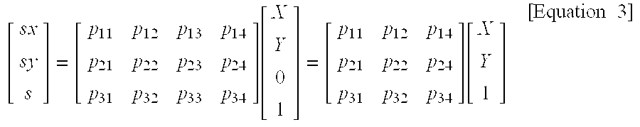
- where, X,Y indicate actual 3D coordinates in projection geometry theory, x, y indicate coordinates in the projected image, s is a scale factor, and p is a value of the projection transformation matrix.
- Also, rearranging
Equation 3 in order to obtain an equation of the projectedcircle Equation 4 is obtained.
- Considering the homogeneous characteristic of the coordinate system in
Equation 4, multiplying terms ofEquation 4 are deleted andEquation 2 is substituted to obtain the following Equation 5.
- Meanwhile, Equation 5 may be rearranged to obtain an equation of an ellipse. Then, the coordinate of the central point of the projected ellipse can be obtained by following Equation 6.

- Where, A′, B′, C′, D′, E′ and F′ consist of a combinations of factors α ij in Equation 5 and r is a radius constant of the circle.
- As can be seen from Equation 6, A′, B′, C′, D′, E′ and F′ are independent from r.
- A straight line connecting the central points of the ellipses is defined as Equation 7 using the coordinates of the central points of the ellipses calculated by Equation 6.
- (B′E′−A′F′)X′+(A′D′−B′C′)Y′+(D′E′+F′C′)=0 [Equation 7]
- Equation 7 is an equation of the straight line including only constant coefficients with respect to r. This means that the central points of the ellipses obtained as a result of the projection is located on the straight line defined independently from the radius of the circle, where X′, Y′ are coordinates of the centers of the ellipses. As the center of the projected concentric circle is same to the center of the ellipses when r=0 in
Equation 2, the center of the circle is also located on the straight line defined by Equation 7. - From the relation that the central points of the projected ellipses are located on one straight line, an algorithm to find the coordinate of the central point of the circle will be now described in detail.
- It is defined that the crossing points of the projected internal ellipse and the straight line are A, B, the crossing points of the external ellipse the straight line are A′, B′, the central point of the circle is O and a given point separated infinitely on the straight line is M ∞. Location of these points can be found in FIG. 6 and FIG. 7 and this positional relation is same in 3D and 2D spaces.
- Meanwhile, a given point infinitely separated from the center of the circle O on the straight line is a point virtually set and is frequently used in projection theory. This point is typically used because it is easy to serve as the boundary value of a condition and it has a characteristic limiting the cross ratio.
- Therefore, a cross ratio Cr (A, O, B and M.) and Cr (A′, O, B′ and M ∞) are same, which is calculated in the same manner in a 3D space by
Equation 8.
- Where, the points that can be found in the image are A, B, A′ and B′, and
Equation 8 has two variables of points O and Mo. These two points are commonly used in the two Equations of Cr (A, O, B and M.) and Cr (A′, O, B and M∞). Therefore, two variables and two equations can be obtained. As a result, the coordinate of point O can be obtained by solving the two Equations. - All the items of below Equation 9 can be found from thus obtained coordinate of the central point of the circle. Also, calibration is performed by finding internal parameters u 0, v0 and f which minimize the value of Equation 9. Calibration of the internal parameters uses below Equation 9.

- In Equation 9, u 0, v0 and f, respectively indicate a principal point and a focal length of the camera. The first two items (α({overscore (n)}1{overscore (n)}2)+β({overscore (n)}3−{overscore (n)}4)) indicate that two concentric circles have the same normal vector and next two items (γ(d1−d2)+λ(d3−d4)) indicate that two concentric circles are located on the plane having the same distance. In addition, next fcur items (ρ1Σ|RC
l (nl,dl)−Rl|+ρ2Σ|RCl (n2,d2)−R2|+ρ3Σ|RCll (n3,d3)−R3|+ρ4Σ|RC ll(n4,d4)−R4|) indicate that a radius obtained from given internal parameters is same as the actual radius. - A concentric circle is drawn on the plane so that the central points of two circles having a radius of 40 mm and 80 mm, respectively are located at one point. Also, as shown in FIG. 4 a and FIG. 4b, images of the circle is taken at two different angles to obtain two images. At this time, a XC-003 camera manufactured by SONY and with focal radius of 8 mm was used.
- After obtaining two projection images (containing the boundary lines), a calibration value as shown in Table 1 is obtained by means of a camera calibration method using the concentric circle pattern according to the present invention.
TABLE 1 Class uO vO αu αv Comparative example 306.70 240.44 1104.2 1112.5 (Z. Zhang) Embodiment of the 309.37 246.01 1104.7 1110.7 present invention - The comparative example (Z.Zhang) in Table 1 shows the calibrated values according to the camera calibration method taught in an article Z. Zhang, “Flexible Camera Calibration by Viewing a Plane From Unknown Orientations”, In Proc. 7th International Conference Computer Vision, Corfu, Greece, pp.666-673, September 1999. Table 1 shows that the calibration value calculated using a concentric circle pattern is similar to the calibration value in the comparative example of Z. Zhang.
- As mentioned above, the method of calibrating internal parameters of a camera using a concentric circle pattern according to the present invention provides the calibration parameters of the camera from images of a 2D concentric circle taken from different angles. Thus, the present invention has an advantage that a concentric circle pattern which is easy to manufacture and maintain.
- Also, the method of calibrating internal parameters of a camera using a concentric circle pattern according to the present invention calculates camera calibration parameters using a plurality of Equations. Therefore, the present invention has an advantage that it can easily calibrate a camera by calculating the calibration parameters.
- The present invention has been described with reference to a particular embodiment in connection with a particular application. Those having ordinary skill in the art and access to the teachings of the present invention will recognize additional modifications and applications within the scope thereof. It is therefore intended by the appended claims to cover any and all such applications, modifications, and embodiments within the scope of the present invention.
Claims (8)
1. A method of calibrating a camera by calculating camera parameters required to obtain geometric information of an object using projection invariable characteristic of a concentric circle comprising the steps of;
a) taking a plurality of images of a calibration pattern consisting of two or more concentric circles located at a same plane and having different radiuses at different angles to obtain images of ellipses as a result of the projection of said concentric circles;
b) calculating the central points of the projected concentric circles using a given algorithm; and
c) calculating the principal point and focal length of said camera for tracing the location of a circle in a 3D space using a nonlinear minimizing method based on the central points calculated in said step b).
2. The method of calibrating a camera according to claim 1 , wherein said concentric circle includes two circles and said step b) includes the steps of:
d) calculating the central points of the two ellipses to obtain a straight line passing through said central points;
e) calculating crossing points of said straight line and said two ellipses; and
f) calculating the coordinate of the central point of said concentric circle using a cross ratio depending on the central point (0) of the concentric circle, a given point (M∞) infinitely separated from the central point of the concentric circle on the straight line passing through the central points of the ellipses, and the crossing points of the straight line and the ellipses.
3. The method of calibrating a camera according to claim 2 , wherein said step d) calculates the straight line passing through the centers of the ellipses by Equation 1:
(B′E′−A′F′)X′+(A′D′−B′C′)Y′+(D′E′+F′C′)=0 (1)
(where A′, B′, C′, D′, E′ and F′ are constants with respect to the radius of the circle and, X′,Y′ are the coordinates of the ellipse center)
4. The method of calibrating a camera according to claim 3 , wherein said step f) calculates the coordinate of the center of the circle by Equation 2:

where A,B are the coordinates of crossing points of an ellipse generated by projection of smaller circle and the straight line, and A′,B′ are the coordinates of crossing points of an ellipse generated by projection of an external circle surrounding the smaller circle and the straight line)
5. The method of calibrating a camera according to claim 3 , wherein said step c) includes the steps of:
g) assuming that the central point and a approximate focal length obtained in said step b) as a principal point focal length;
h) estimating the location of the circle in a 3D space using said principle point and focal length; and
i) repeating said steps g) and h) using a given nonlinear minimization algorithm using a normal vector of said concentric circle, a vertical distance from an original point and the radius of the concentric circle based on the location of the circle obtained in said step h), so that below Equation 3 is minimized.
F(u 0,ν0 ,f)=
α({overscore (n)} 1 −{overscore (n)} 2)2+β({overscore (n)} 3 −{overscore (n)} 4)2+γ(d 1 −d 2)2+λ(d 3 −d 4)2+ρ1 Σ|R C 1 (n 1 ,d 1)−R 1|+ρ2 Σ|R C 2 (n 2 ,d 2)−R2|+ρ3 Σ|R C 1 (n 3 ,d 3)−R 3|+ρ4ρ4 Σ|R C 4 (n 4 ,d 4)−R 4| (3)
where u0, v0 and f indicate a principle point and a focal length of the camera, the first two items in Equation 3 indicate that two concentric circles have the same normal vector, next two items in Equation 3 indicate that two concentric circles are located on a plane having the same length, and next four items indicate that a radius obtained from given internal parameters is same as the actual radius.
6. A system for calibrating internal parameters of a camera for calibrating parameters between an actual object and images of the object, comprising;
a camera;
a calibration pattern located on a same plane and consisting of two or more concentric circles having different radiuses, the image of which is taken by said camera; and
a controller for calculating a straight line connecting the central points of the images of ellipses obtained by projecting said calibration pattern of concentric circles to said camera at a given angle, and finding crossing points of said straight line and said projected ellipses to obtain the central point coordinate of the concentric circle using a cross ratio (Cr), and tracing the location of the circle in a 3D space based on the coordinate of the central point of the concentric circle to calculate a principal point and focal length of the camera.
7. The system for calibrating internal parameters of a camera according to claim 6 , wherein said principal point and focal length are obtained using a given nonlinear minimization algorithm so that below Equation 3 is minimized.
F(u 0,ν0 ,f)=
α({overscore (n)} 1 −{overscore (n)} 2)2+β({overscore (n)} 3 −{overscore (n)} 4)2+γ(d 1 −d 2)2+λ(d 3 −d 4)2+ρ1 Σ|R C 1 (n 1 ,d 1)−R 1|+ρ2 Σ|R C 2 (n 2 ,d 2)−R2|+ρ3 Σ|R C 1 (n 3 ,d 3)−R 3|+ρ4ρ4 Σ|R C 4 (n 4 ,d 4)−R 4| (3)
where u0, v0 and f indicate a principle point and a focal length of the camera, the first two items in Equation 3 indicate that two concentric circles have the same normal vector, next two items in Equation 3 indicate that two concentric circles are located on a plane having the same length, and next four items indicate that a radius obtained from given internal parameters is same as the actual radius.
8. The system for calibrating internal parameters of a camera according to claim 6 , wherein said camera is a CCD camera.
Priority Applications (1)
| Application Number | Priority Date | Filing Date | Title |
|---|---|---|---|
| US11/074,562 US7155030B2 (en) | 2001-04-02 | 2005-03-08 | Camera calibration system using planar concentric circles and method thereof |
Applications Claiming Priority (2)
| Application Number | Priority Date | Filing Date | Title |
|---|---|---|---|
| KR10-2001-0017418A KR100386090B1 (en) | 2001-04-02 | 2001-04-02 | Camera calibration system and method using planar concentric circles |
| KR2001-17418 | 2001-04-02 |
Related Child Applications (1)
| Application Number | Title | Priority Date | Filing Date |
|---|---|---|---|
| US11/074,562 Continuation-In-Part US7155030B2 (en) | 2001-04-02 | 2005-03-08 | Camera calibration system using planar concentric circles and method thereof |
Publications (1)
| Publication Number | Publication Date |
|---|---|
| US20020186897A1 true US20020186897A1 (en) | 2002-12-12 |
Family
ID=19707748
Family Applications (2)
| Application Number | Title | Priority Date | Filing Date |
|---|---|---|---|
| US09/919,086 Abandoned US20020186897A1 (en) | 2001-04-02 | 2001-07-31 | Camera calibration system using planar concentric circles and method thereof |
| US11/074,562 Expired - Fee Related US7155030B2 (en) | 2001-04-02 | 2005-03-08 | Camera calibration system using planar concentric circles and method thereof |
Family Applications After (1)
| Application Number | Title | Priority Date | Filing Date |
|---|---|---|---|
| US11/074,562 Expired - Fee Related US7155030B2 (en) | 2001-04-02 | 2005-03-08 | Camera calibration system using planar concentric circles and method thereof |
Country Status (2)
| Country | Link |
|---|---|
| US (2) | US20020186897A1 (en) |
| KR (1) | KR100386090B1 (en) |
Cited By (49)
| Publication number | Priority date | Publication date | Assignee | Title |
|---|---|---|---|---|
| US20050228555A1 (en) * | 2003-08-20 | 2005-10-13 | Samsung Electronics Co., Ltd. | Method of constructing artificial mark for autonomous driving, apparatus and method of determining position of intelligent system using artificial mark and intelligent system employing the same |
| US20090066643A1 (en) * | 2007-09-07 | 2009-03-12 | Samsung Electronics Co., Ltd | Touch screen panel to input multi-dimension values and method for controlling touch screen panel |
| WO2009056050A1 (en) * | 2007-10-24 | 2009-05-07 | Shenzhen Huawei Communication Technologies Co. , Ltd. | Video camera calibration method and device thereof |
| CN101303768B (en) * | 2008-06-17 | 2010-06-23 | 东南大学 | Method for correcting circle center error of circular index point when translating camera perspective projection |
| CN101813465A (en) * | 2010-03-30 | 2010-08-25 | 中北大学 | Monocular vision measuring method of non-contact precision measuring corner |
| CN102622744A (en) * | 2012-01-17 | 2012-08-01 | 浙江大学 | Telephoto camera calibration method based on polynomial projection model |
| CN102853903A (en) * | 2011-06-28 | 2013-01-02 | 中国科学院西安光学精密机械研究所 | Method for demarcating linearity indexes of scientific grade Charge-coupled Device (CCD) |
| US20130033596A1 (en) * | 2011-08-03 | 2013-02-07 | The Boeing Company | Projection aided feature measurement using uncalibrated camera |
| CN102103746B (en) * | 2009-12-21 | 2013-02-13 | 云南大学 | Method for calibrating parameters in camera through solving circular ring points by utilizing regular tetrahedron |
| CN102982550A (en) * | 2012-12-14 | 2013-03-20 | 云南大学 | Method of solving intrinsic parameters of camera with regular pentagonal prismatic table |
| CN102982549A (en) * | 2012-12-14 | 2013-03-20 | 云南大学 | Method of solving intrinsic parameters of camera with two center-sharing and principal axis orthonormal intersected identical ellipses |
| CN103592285A (en) * | 2013-11-26 | 2014-02-19 | 长春新产业光电技术有限公司 | Non-linear calibration method of Raman spectrum wavelength and CCD picture element |
| CN104155003A (en) * | 2014-06-23 | 2014-11-19 | 中国科学院光电研究院 | High-stability rotating mirror interferometer |
| CN104165693A (en) * | 2014-07-29 | 2014-11-26 | 中国科学院西安光学精密机械研究所 | Large-aperture static-state interference spectrum imaging instrument interferogram optical splicing method |
| CN104165692A (en) * | 2014-07-25 | 2014-11-26 | 华东师范大学 | Portable spectrum rapid detector based on quantum effect photodetector |
| CN104331900A (en) * | 2014-11-25 | 2015-02-04 | 湖南科技大学 | Corner sub-pixel positioning method in CCD (charge coupled device) camera calibration |
| CN104380064A (en) * | 2012-06-15 | 2015-02-25 | 株式会社日立高新技术 | Optical signal detecting circuit, light volume detecting device, and charged particle beam device |
| CN104848944A (en) * | 2015-05-28 | 2015-08-19 | 上海理工大学 | Z scanning optical polarization measurement device and measurement method thereof |
| CN105241427A (en) * | 2015-10-13 | 2016-01-13 | 中北大学 | Single-camera vision measurement method using concentric circle target for measuring position posture and rotating angle of object |
| CN106017667A (en) * | 2016-07-19 | 2016-10-12 | 苏州市职业大学 | Multifunctional ultraviolet ray detector powered by solar energy |
| CN106017669A (en) * | 2016-05-13 | 2016-10-12 | 中国科学院紫金山天文台 | Multifunctional reading circuit system for KID detector array |
| CN106485753A (en) * | 2016-09-09 | 2017-03-08 | 奇瑞汽车股份有限公司 | Method and apparatus for the camera calibration of pilotless automobile |
| US20180165824A1 (en) * | 2016-12-09 | 2018-06-14 | Hand Held Products, Inc. | Calibrating a dimensioner using ratios of measurable parameters of optically-perceptible geometric elements |
| CN108908399A (en) * | 2018-06-11 | 2018-11-30 | 杭州灵西机器人智能科技有限公司 | A kind of Robotic Hand-Eye Calibration method based on concentric loop template |
| US10228452B2 (en) | 2013-06-07 | 2019-03-12 | Hand Held Products, Inc. | Method of error correction for 3D imaging device |
| US10240914B2 (en) | 2014-08-06 | 2019-03-26 | Hand Held Products, Inc. | Dimensioning system with guided alignment |
| US10249030B2 (en) | 2015-10-30 | 2019-04-02 | Hand Held Products, Inc. | Image transformation for indicia reading |
| US10247547B2 (en) | 2015-06-23 | 2019-04-02 | Hand Held Products, Inc. | Optical pattern projector |
| US10321127B2 (en) | 2012-08-20 | 2019-06-11 | Intermec Ip Corp. | Volume dimensioning system calibration systems and methods |
| US10339352B2 (en) | 2016-06-03 | 2019-07-02 | Hand Held Products, Inc. | Wearable metrological apparatus |
| US10393508B2 (en) | 2014-10-21 | 2019-08-27 | Hand Held Products, Inc. | Handheld dimensioning system with measurement-conformance feedback |
| US10402956B2 (en) | 2014-10-10 | 2019-09-03 | Hand Held Products, Inc. | Image-stitching for dimensioning |
| US10467806B2 (en) | 2012-05-04 | 2019-11-05 | Intermec Ip Corp. | Volume dimensioning systems and methods |
| CN110874606A (en) * | 2018-08-31 | 2020-03-10 | 深圳中科飞测科技有限公司 | Matching method, three-dimensional morphology detection method and system thereof, and non-transitory computer readable medium |
| US10584962B2 (en) | 2018-05-01 | 2020-03-10 | Hand Held Products, Inc | System and method for validating physical-item security |
| US10593130B2 (en) | 2015-05-19 | 2020-03-17 | Hand Held Products, Inc. | Evaluating image values |
| US10612958B2 (en) | 2015-07-07 | 2020-04-07 | Hand Held Products, Inc. | Mobile dimensioner apparatus to mitigate unfair charging practices in commerce |
| US10635922B2 (en) | 2012-05-15 | 2020-04-28 | Hand Held Products, Inc. | Terminals and methods for dimensioning objects |
| US10733748B2 (en) | 2017-07-24 | 2020-08-04 | Hand Held Products, Inc. | Dual-pattern optical 3D dimensioning |
| US10747227B2 (en) | 2016-01-27 | 2020-08-18 | Hand Held Products, Inc. | Vehicle positioning and object avoidance |
| US10775165B2 (en) | 2014-10-10 | 2020-09-15 | Hand Held Products, Inc. | Methods for improving the accuracy of dimensioning-system measurements |
| JPWO2020208686A1 (en) * | 2019-04-08 | 2020-10-15 | ||
| US10908013B2 (en) | 2012-10-16 | 2021-02-02 | Hand Held Products, Inc. | Dimensioning system |
| US11029762B2 (en) | 2015-07-16 | 2021-06-08 | Hand Held Products, Inc. | Adjusting dimensioning results using augmented reality |
| US11047672B2 (en) | 2017-03-28 | 2021-06-29 | Hand Held Products, Inc. | System for optically dimensioning |
| US20210233274A1 (en) * | 2018-04-26 | 2021-07-29 | Continental Automotive Gmbh | Online Evaluation for Camera Intrinsic Parameters |
| CN113506347A (en) * | 2021-06-29 | 2021-10-15 | 湖南泽塔科技有限公司 | Camera internal reference processing method and system based on single picture |
| CN113894799A (en) * | 2021-12-08 | 2022-01-07 | 北京云迹科技有限公司 | Robot and marker identification method and device for assisting environment positioning |
| US11639846B2 (en) | 2019-09-27 | 2023-05-02 | Honeywell International Inc. | Dual-pattern optical 3D dimensioning |
Families Citing this family (29)
| Publication number | Priority date | Publication date | Assignee | Title |
|---|---|---|---|---|
| JP4147059B2 (en) * | 2002-07-03 | 2008-09-10 | 株式会社トプコン | Calibration data measuring device, measuring method and measuring program, computer-readable recording medium, and image data processing device |
| JP4598372B2 (en) * | 2003-05-26 | 2010-12-15 | 株式会社トプコン | 3D field for calibration, 3D field for calibration |
| KR100690857B1 (en) * | 2005-12-02 | 2007-03-09 | 엘지전자 주식회사 | Apparatus for controlling camera alignment of mobile communications terminal |
| KR100793838B1 (en) | 2006-09-27 | 2008-01-11 | 한국전자통신연구원 | Appratus for findinng the motion of camera, system and method for supporting augmented reality in ocean scene using the appratus |
| US8238648B2 (en) * | 2006-12-04 | 2012-08-07 | Electronics And Telecommunications Research Institute | Apparatus and method for estimating focal length of camera |
| KR100966592B1 (en) | 2007-12-17 | 2010-06-29 | 한국전자통신연구원 | Method for calibrating a camera with homography of imaged parallelogram |
| TWI426775B (en) * | 2010-12-17 | 2014-02-11 | Ind Tech Res Inst | Camera recalibration system and the method thereof |
| KR101694294B1 (en) | 2010-12-22 | 2017-01-09 | 한국전자통신연구원 | Apparatus and method for calibrating camera with imaged parallelograms and multi-view constraints |
| US8872897B2 (en) | 2011-05-11 | 2014-10-28 | Intel Corporation | Camera calibration using an easily produced 3D calibration pattern |
| US8743214B2 (en) * | 2011-05-11 | 2014-06-03 | Intel Corporation | Display screen for camera calibration |
| KR101638173B1 (en) * | 2011-09-06 | 2016-07-12 | 한국전자통신연구원 | Method and apparatus for providing automated detection of calibration |
| US9841367B2 (en) | 2011-09-16 | 2017-12-12 | The University Of North Carolina At Charlotte | Methods and devices for optical sorting of microspheres based on their resonant optical properties |
| CN102930551B (en) * | 2012-11-22 | 2015-05-06 | 云南大学 | Camera intrinsic parameters determined by utilizing projected coordinate and epipolar line of centres of circles |
| US9519968B2 (en) | 2012-12-13 | 2016-12-13 | Hewlett-Packard Development Company, L.P. | Calibrating visual sensors using homography operators |
| CN103116892A (en) * | 2013-03-15 | 2013-05-22 | 云南大学 | Linear solving of video camera internal parameters by utilizing two intersected same circles and common tangent |
| CN103247048A (en) * | 2013-05-10 | 2013-08-14 | 东南大学 | Camera mixing calibration method based on quadratic curve and straight lines |
| CA2819956C (en) | 2013-07-02 | 2022-07-12 | Guy Martin | High accuracy camera modelling and calibration method |
| JP6217227B2 (en) * | 2013-08-12 | 2017-10-25 | 株式会社リコー | Calibration apparatus, method and program |
| CN104637042A (en) * | 2013-11-06 | 2015-05-20 | 北京计算机技术及应用研究所 | Camera calibration method based on circular reference object and system thereof |
| US10241616B2 (en) | 2014-02-28 | 2019-03-26 | Hewlett-Packard Development Company, L.P. | Calibration of sensors and projector |
| CN104318555B (en) * | 2014-10-13 | 2017-02-08 | 江南大学 | Accurate positioning method of center projection point in target image |
| KR101973460B1 (en) | 2015-02-09 | 2019-05-02 | 한국전자통신연구원 | Device and method for multiview image calibration |
| CN104794704B (en) * | 2015-03-27 | 2017-11-17 | 华为技术有限公司 | A kind of calibrating template, template detection method, apparatus and terminal |
| CN106683135A (en) * | 2015-11-09 | 2017-05-17 | 宁波舜宇光电信息有限公司 | Method for searching optic center of lens |
| US10089753B1 (en) * | 2017-07-05 | 2018-10-02 | Almotive Kft. | Method, system and computer-readable medium for camera calibration |
| CN107507244A (en) * | 2017-07-26 | 2017-12-22 | 成都通甲优博科技有限责任公司 | Camera calibration method, proving operation method and the caliberating device of a kind of single-frame images |
| CN107705335A (en) * | 2017-09-21 | 2018-02-16 | 珠海中视科技有限公司 | Demarcate the non-method that ken line sweeps laser range finder and measures camera orientation altogether |
| WO2020118637A1 (en) * | 2018-12-13 | 2020-06-18 | 昂纳自动化技术(深圳)有限公司 | Camera calibration board, calibration method and camera |
| US11074720B1 (en) * | 2020-02-07 | 2021-07-27 | Aptiv Technologies Limited | System and method for calibrating intrinsic parameters of a camera using optical raytracing techniques |
Citations (7)
| Publication number | Priority date | Publication date | Assignee | Title |
|---|---|---|---|---|
| US5559334A (en) * | 1995-05-22 | 1996-09-24 | General Electric Company | Epipolar reconstruction of 3D structures |
| US5918196A (en) * | 1996-11-29 | 1999-06-29 | Cognex Corporation | Vision system for analyzing solid-of-revolution radius profile |
| US6088098A (en) * | 1998-01-17 | 2000-07-11 | Robert Bosch Gmbh | Calibration method for a laser-based split-beam method |
| US6195455B1 (en) * | 1998-07-01 | 2001-02-27 | Intel Corporation | Imaging device orientation information through analysis of test images |
| US6437823B1 (en) * | 1999-04-30 | 2002-08-20 | Microsoft Corporation | Method and system for calibrating digital cameras |
| US6671400B1 (en) * | 2000-09-28 | 2003-12-30 | Tateyama R & D Co., Ltd. | Panoramic image navigation system using neural network for correction of image distortion |
| US6750860B1 (en) * | 1998-12-28 | 2004-06-15 | Microsoft Corporation | Rendering with concentric mosaics |
Family Cites Families (4)
| Publication number | Priority date | Publication date | Assignee | Title |
|---|---|---|---|---|
| US5054907A (en) * | 1989-12-22 | 1991-10-08 | Phoenix Laser Systems, Inc. | Ophthalmic diagnostic apparatus and method |
| US5886767A (en) * | 1996-10-09 | 1999-03-23 | Snook; Richard K. | Keratometry system and method for measuring physical parameters of the cornea |
| US6995762B1 (en) * | 2001-09-13 | 2006-02-07 | Symbol Technologies, Inc. | Measurement of dimensions of solid objects from two-dimensional image(s) |
| JP3624288B2 (en) * | 2001-09-17 | 2005-03-02 | 株式会社日立製作所 | Store management system |
-
2001
- 2001-04-02 KR KR10-2001-0017418A patent/KR100386090B1/en active IP Right Grant
- 2001-07-31 US US09/919,086 patent/US20020186897A1/en not_active Abandoned
-
2005
- 2005-03-08 US US11/074,562 patent/US7155030B2/en not_active Expired - Fee Related
Patent Citations (7)
| Publication number | Priority date | Publication date | Assignee | Title |
|---|---|---|---|---|
| US5559334A (en) * | 1995-05-22 | 1996-09-24 | General Electric Company | Epipolar reconstruction of 3D structures |
| US5918196A (en) * | 1996-11-29 | 1999-06-29 | Cognex Corporation | Vision system for analyzing solid-of-revolution radius profile |
| US6088098A (en) * | 1998-01-17 | 2000-07-11 | Robert Bosch Gmbh | Calibration method for a laser-based split-beam method |
| US6195455B1 (en) * | 1998-07-01 | 2001-02-27 | Intel Corporation | Imaging device orientation information through analysis of test images |
| US6750860B1 (en) * | 1998-12-28 | 2004-06-15 | Microsoft Corporation | Rendering with concentric mosaics |
| US6437823B1 (en) * | 1999-04-30 | 2002-08-20 | Microsoft Corporation | Method and system for calibrating digital cameras |
| US6671400B1 (en) * | 2000-09-28 | 2003-12-30 | Tateyama R & D Co., Ltd. | Panoramic image navigation system using neural network for correction of image distortion |
Cited By (67)
| Publication number | Priority date | Publication date | Assignee | Title |
|---|---|---|---|---|
| US7437226B2 (en) * | 2003-08-20 | 2008-10-14 | Samsung Electronics Co., Ltd. | Method of constructing artificial mark for autonomous driving, apparatus and method of determining position of intelligent system using artificial mark and intelligent system employing the same |
| US20050228555A1 (en) * | 2003-08-20 | 2005-10-13 | Samsung Electronics Co., Ltd. | Method of constructing artificial mark for autonomous driving, apparatus and method of determining position of intelligent system using artificial mark and intelligent system employing the same |
| US8229619B2 (en) | 2003-08-20 | 2012-07-24 | Samsung Electronics Co., Ltd. | Method of constructing artificial mark for autonomous driving, apparatus and method of determining position of intelligent system using artificial mark and intelligent system employing the same |
| US8812992B2 (en) * | 2007-09-07 | 2014-08-19 | Samsung Electronics Co., Ltd. | Touch screen panel to input multi-dimension values and method for controlling touch screen panel |
| US20090066643A1 (en) * | 2007-09-07 | 2009-03-12 | Samsung Electronics Co., Ltd | Touch screen panel to input multi-dimension values and method for controlling touch screen panel |
| US20100259624A1 (en) * | 2007-10-24 | 2010-10-14 | Kai Li | Method and apparatus for calibrating video camera |
| WO2009056050A1 (en) * | 2007-10-24 | 2009-05-07 | Shenzhen Huawei Communication Technologies Co. , Ltd. | Video camera calibration method and device thereof |
| US8436904B2 (en) | 2007-10-24 | 2013-05-07 | Huawei Device Co., Ltd. | Method and apparatus for calibrating video camera |
| CN101303768B (en) * | 2008-06-17 | 2010-06-23 | 东南大学 | Method for correcting circle center error of circular index point when translating camera perspective projection |
| CN102103746B (en) * | 2009-12-21 | 2013-02-13 | 云南大学 | Method for calibrating parameters in camera through solving circular ring points by utilizing regular tetrahedron |
| CN101813465A (en) * | 2010-03-30 | 2010-08-25 | 中北大学 | Monocular vision measuring method of non-contact precision measuring corner |
| CN102853903A (en) * | 2011-06-28 | 2013-01-02 | 中国科学院西安光学精密机械研究所 | Method for demarcating linearity indexes of scientific grade Charge-coupled Device (CCD) |
| US20130033596A1 (en) * | 2011-08-03 | 2013-02-07 | The Boeing Company | Projection aided feature measurement using uncalibrated camera |
| US8922647B2 (en) * | 2011-08-03 | 2014-12-30 | The Boeing Company | Projection aided feature measurement using uncalibrated camera |
| CN102622744A (en) * | 2012-01-17 | 2012-08-01 | 浙江大学 | Telephoto camera calibration method based on polynomial projection model |
| US10467806B2 (en) | 2012-05-04 | 2019-11-05 | Intermec Ip Corp. | Volume dimensioning systems and methods |
| US10635922B2 (en) | 2012-05-15 | 2020-04-28 | Hand Held Products, Inc. | Terminals and methods for dimensioning objects |
| CN104380064A (en) * | 2012-06-15 | 2015-02-25 | 株式会社日立高新技术 | Optical signal detecting circuit, light volume detecting device, and charged particle beam device |
| US10805603B2 (en) | 2012-08-20 | 2020-10-13 | Intermec Ip Corp. | Volume dimensioning system calibration systems and methods |
| US10321127B2 (en) | 2012-08-20 | 2019-06-11 | Intermec Ip Corp. | Volume dimensioning system calibration systems and methods |
| US10908013B2 (en) | 2012-10-16 | 2021-02-02 | Hand Held Products, Inc. | Dimensioning system |
| CN102982549A (en) * | 2012-12-14 | 2013-03-20 | 云南大学 | Method of solving intrinsic parameters of camera with two center-sharing and principal axis orthonormal intersected identical ellipses |
| CN102982550A (en) * | 2012-12-14 | 2013-03-20 | 云南大学 | Method of solving intrinsic parameters of camera with regular pentagonal prismatic table |
| US10228452B2 (en) | 2013-06-07 | 2019-03-12 | Hand Held Products, Inc. | Method of error correction for 3D imaging device |
| CN103592285A (en) * | 2013-11-26 | 2014-02-19 | 长春新产业光电技术有限公司 | Non-linear calibration method of Raman spectrum wavelength and CCD picture element |
| CN104155003A (en) * | 2014-06-23 | 2014-11-19 | 中国科学院光电研究院 | High-stability rotating mirror interferometer |
| CN104165692A (en) * | 2014-07-25 | 2014-11-26 | 华东师范大学 | Portable spectrum rapid detector based on quantum effect photodetector |
| CN104165693A (en) * | 2014-07-29 | 2014-11-26 | 中国科学院西安光学精密机械研究所 | Large-aperture static-state interference spectrum imaging instrument interferogram optical splicing method |
| US10240914B2 (en) | 2014-08-06 | 2019-03-26 | Hand Held Products, Inc. | Dimensioning system with guided alignment |
| US10810715B2 (en) | 2014-10-10 | 2020-10-20 | Hand Held Products, Inc | System and method for picking validation |
| US10859375B2 (en) | 2014-10-10 | 2020-12-08 | Hand Held Products, Inc. | Methods for improving the accuracy of dimensioning-system measurements |
| US10775165B2 (en) | 2014-10-10 | 2020-09-15 | Hand Held Products, Inc. | Methods for improving the accuracy of dimensioning-system measurements |
| US10402956B2 (en) | 2014-10-10 | 2019-09-03 | Hand Held Products, Inc. | Image-stitching for dimensioning |
| US10393508B2 (en) | 2014-10-21 | 2019-08-27 | Hand Held Products, Inc. | Handheld dimensioning system with measurement-conformance feedback |
| CN104331900A (en) * | 2014-11-25 | 2015-02-04 | 湖南科技大学 | Corner sub-pixel positioning method in CCD (charge coupled device) camera calibration |
| US11403887B2 (en) | 2015-05-19 | 2022-08-02 | Hand Held Products, Inc. | Evaluating image values |
| US11906280B2 (en) | 2015-05-19 | 2024-02-20 | Hand Held Products, Inc. | Evaluating image values |
| US10593130B2 (en) | 2015-05-19 | 2020-03-17 | Hand Held Products, Inc. | Evaluating image values |
| CN104848944A (en) * | 2015-05-28 | 2015-08-19 | 上海理工大学 | Z scanning optical polarization measurement device and measurement method thereof |
| US10247547B2 (en) | 2015-06-23 | 2019-04-02 | Hand Held Products, Inc. | Optical pattern projector |
| US10612958B2 (en) | 2015-07-07 | 2020-04-07 | Hand Held Products, Inc. | Mobile dimensioner apparatus to mitigate unfair charging practices in commerce |
| US11029762B2 (en) | 2015-07-16 | 2021-06-08 | Hand Held Products, Inc. | Adjusting dimensioning results using augmented reality |
| CN105241427A (en) * | 2015-10-13 | 2016-01-13 | 中北大学 | Single-camera vision measurement method using concentric circle target for measuring position posture and rotating angle of object |
| US10249030B2 (en) | 2015-10-30 | 2019-04-02 | Hand Held Products, Inc. | Image transformation for indicia reading |
| US10747227B2 (en) | 2016-01-27 | 2020-08-18 | Hand Held Products, Inc. | Vehicle positioning and object avoidance |
| CN106017669A (en) * | 2016-05-13 | 2016-10-12 | 中国科学院紫金山天文台 | Multifunctional reading circuit system for KID detector array |
| US10872214B2 (en) | 2016-06-03 | 2020-12-22 | Hand Held Products, Inc. | Wearable metrological apparatus |
| US10339352B2 (en) | 2016-06-03 | 2019-07-02 | Hand Held Products, Inc. | Wearable metrological apparatus |
| CN106017667A (en) * | 2016-07-19 | 2016-10-12 | 苏州市职业大学 | Multifunctional ultraviolet ray detector powered by solar energy |
| CN106485753A (en) * | 2016-09-09 | 2017-03-08 | 奇瑞汽车股份有限公司 | Method and apparatus for the camera calibration of pilotless automobile |
| US20180165824A1 (en) * | 2016-12-09 | 2018-06-14 | Hand Held Products, Inc. | Calibrating a dimensioner using ratios of measurable parameters of optically-perceptible geometric elements |
| US10909708B2 (en) * | 2016-12-09 | 2021-02-02 | Hand Held Products, Inc. | Calibrating a dimensioner using ratios of measurable parameters of optic ally-perceptible geometric elements |
| US11047672B2 (en) | 2017-03-28 | 2021-06-29 | Hand Held Products, Inc. | System for optically dimensioning |
| US10733748B2 (en) | 2017-07-24 | 2020-08-04 | Hand Held Products, Inc. | Dual-pattern optical 3D dimensioning |
| US11562503B2 (en) * | 2018-04-26 | 2023-01-24 | Continental Automotive Gmbh | Online evaluation for camera intrinsic parameters |
| US20210233274A1 (en) * | 2018-04-26 | 2021-07-29 | Continental Automotive Gmbh | Online Evaluation for Camera Intrinsic Parameters |
| US10584962B2 (en) | 2018-05-01 | 2020-03-10 | Hand Held Products, Inc | System and method for validating physical-item security |
| CN108908399A (en) * | 2018-06-11 | 2018-11-30 | 杭州灵西机器人智能科技有限公司 | A kind of Robotic Hand-Eye Calibration method based on concentric loop template |
| CN110874606A (en) * | 2018-08-31 | 2020-03-10 | 深圳中科飞测科技有限公司 | Matching method, three-dimensional morphology detection method and system thereof, and non-transitory computer readable medium |
| WO2020208686A1 (en) * | 2019-04-08 | 2020-10-15 | 日本電気株式会社 | Camera calibration device, camera calibration method, and non-transitory computer-readable medium having program stored thereon |
| JP7151879B2 (en) | 2019-04-08 | 2022-10-12 | 日本電気株式会社 | Camera calibration device, camera calibration method, and program |
| US11521333B2 (en) | 2019-04-08 | 2022-12-06 | Nec Corporation | Camera calibration apparatus, camera calibration method, and non-transitory computer readable medium storing program |
| JPWO2020208686A1 (en) * | 2019-04-08 | 2020-10-15 | ||
| US11830223B2 (en) | 2019-04-08 | 2023-11-28 | Nec Corporation | Camera calibration apparatus, camera calibration method, and nontransitory computer readable medium storing program |
| US11639846B2 (en) | 2019-09-27 | 2023-05-02 | Honeywell International Inc. | Dual-pattern optical 3D dimensioning |
| CN113506347A (en) * | 2021-06-29 | 2021-10-15 | 湖南泽塔科技有限公司 | Camera internal reference processing method and system based on single picture |
| CN113894799A (en) * | 2021-12-08 | 2022-01-07 | 北京云迹科技有限公司 | Robot and marker identification method and device for assisting environment positioning |
Also Published As
| Publication number | Publication date |
|---|---|
| US20050207640A1 (en) | 2005-09-22 |
| KR20020077685A (en) | 2002-10-14 |
| US7155030B2 (en) | 2006-12-26 |
| KR100386090B1 (en) | 2003-06-02 |
Similar Documents
| Publication | Publication Date | Title |
|---|---|---|
| US20020186897A1 (en) | Camera calibration system using planar concentric circles and method thereof | |
| US6947610B2 (en) | Method of correcting an image with perspective distortion and producing an artificial image with perspective distortion | |
| US11227144B2 (en) | Image processing device and method for detecting image of object to be detected from input data | |
| US7659921B2 (en) | Distance measurement apparatus, distance measurement method, and distance measurement program | |
| US7894661B2 (en) | Calibration apparatus, calibration method, program for calibration, and calibration jig | |
| US8208029B2 (en) | Method and system for calibrating camera with rectification homography of imaged parallelogram | |
| US11521333B2 (en) | Camera calibration apparatus, camera calibration method, and non-transitory computer readable medium storing program | |
| KR19990067567A (en) | Vector Correlation System for Automatic Positioning of Patterns in Images | |
| CN101563709A (en) | Calibrating a camera system | |
| CN111750804B (en) | Object measuring method and device | |
| US20220180560A1 (en) | Camera calibration apparatus, camera calibration method, and nontransitory computer readable medium storing program | |
| KR20010071343A (en) | Method of accurately locating the fractional position of a template match point | |
| KR102289688B1 (en) | Method for Estimating 3D Marker Cordinetes of Optical Position Tracking System | |
| US10628968B1 (en) | Systems and methods of calibrating a depth-IR image offset | |
| US7251356B2 (en) | Method for estimation of fundamental matrix in implementing a stereo vision | |
| Yamauchi et al. | Calibration of a structured light system by observing planar object from unknown viewpoints | |
| US6640201B1 (en) | Method for comparing points sets | |
| US6901161B1 (en) | Image-processing computer system for photogrammetric analytical measurement | |
| JP2000171214A (en) | Corresponding point retrieving method and three- dimensional position measuring method utilizing same | |
| EP1828980B1 (en) | Optimized image registration using composite registration vectors | |
| US6456741B1 (en) | Structure-guided image measurement method | |
| JPH0618221A (en) | Integration of multi-viewpoint distance data | |
| JP3207023B2 (en) | Calibration method of image measurement device | |
| US20230093694A1 (en) | Projection transformation parameter estimation device, projection transformation parameter estimation method, and computer readable medium storing program thereof | |
| Rosebrock et al. | Complete generic camera calibration and modeling using spline surfaces |
Legal Events
| Date | Code | Title | Description |
|---|---|---|---|
| AS | Assignment |
Owner name: KOREA ADVANCED INSTITUTE OF SCIENCE AND TECHNOLOGY Free format text: ASSIGNMENT OF ASSIGNORS INTEREST;ASSIGNORS:KIM, JUN-SIK;KWEON, IN-SO;REEL/FRAME:012041/0429 Effective date: 20010716 |
|
| STCB | Information on status: application discontinuation |
Free format text: ABANDONED -- FAILURE TO RESPOND TO AN OFFICE ACTION |