US20030191409A1 - Method and apparatus for determining changes in intracranial pressure utilizing measurement of the circumferential expansion or contraction of a patient's skull - Google Patents
Method and apparatus for determining changes in intracranial pressure utilizing measurement of the circumferential expansion or contraction of a patient's skull Download PDFInfo
- Publication number
- US20030191409A1 US20030191409A1 US10/121,932 US12193202A US2003191409A1 US 20030191409 A1 US20030191409 A1 US 20030191409A1 US 12193202 A US12193202 A US 12193202A US 2003191409 A1 US2003191409 A1 US 2003191409A1
- Authority
- US
- United States
- Prior art keywords
- skull
- wave
- change
- transmitting
- receiving
- Prior art date
- Legal status (The legal status is an assumption and is not a legal conclusion. Google has not performed a legal analysis and makes no representation as to the accuracy of the status listed.)
- Granted
Links
Images

Classifications
-
- A—HUMAN NECESSITIES
- A61—MEDICAL OR VETERINARY SCIENCE; HYGIENE
- A61B—DIAGNOSIS; SURGERY; IDENTIFICATION
- A61B5/00—Measuring for diagnostic purposes; Identification of persons
- A61B5/68—Arrangements of detecting, measuring or recording means, e.g. sensors, in relation to patient
- A61B5/6801—Arrangements of detecting, measuring or recording means, e.g. sensors, in relation to patient specially adapted to be attached to or worn on the body surface
- A61B5/6813—Specially adapted to be attached to a specific body part
- A61B5/6814—Head
-
- A—HUMAN NECESSITIES
- A61—MEDICAL OR VETERINARY SCIENCE; HYGIENE
- A61B—DIAGNOSIS; SURGERY; IDENTIFICATION
- A61B5/00—Measuring for diagnostic purposes; Identification of persons
- A61B5/03—Detecting, measuring or recording fluid pressure within the body other than blood pressure, e.g. cerebral pressure; Measuring pressure in body tissues or organs
- A61B5/031—Intracranial pressure
-
- A—HUMAN NECESSITIES
- A61—MEDICAL OR VETERINARY SCIENCE; HYGIENE
- A61B—DIAGNOSIS; SURGERY; IDENTIFICATION
- A61B8/00—Diagnosis using ultrasonic, sonic or infrasonic waves
- A61B8/08—Detecting organic movements or changes, e.g. tumours, cysts, swellings
- A61B8/0808—Detecting organic movements or changes, e.g. tumours, cysts, swellings for diagnosis of the brain
-
- A—HUMAN NECESSITIES
- A61—MEDICAL OR VETERINARY SCIENCE; HYGIENE
- A61B—DIAGNOSIS; SURGERY; IDENTIFICATION
- A61B8/00—Diagnosis using ultrasonic, sonic or infrasonic waves
- A61B8/08—Detecting organic movements or changes, e.g. tumours, cysts, swellings
- A61B8/0875—Detecting organic movements or changes, e.g. tumours, cysts, swellings for diagnosis of bone
Definitions
- the present invention relates broadly to the field of apparatuses and methods for determining changes in intracranial pressure (“ICP”) by measuring the effects of these changes on a patient's skull.
- ICP intracranial pressure
- the apparatus and method of the present invention use the variation of the surface wave propagation parameters of the patient's skull to determine the change in ICP.
- the apparatus comprises a measuring device, transmit and receive transducers, and transmit and receive angle blocks wherein the transmit and receive transducers are mounted to the transmit and receive angle blocks, respectively.
- the transmit and receive angle blocks each have surfaces that are configured to contact the skull.
- the apparatus further includes a mounting strut to which the transmit and receive angle blocks are movably attached.
- the mounting strut is adjustable in overall length so as to accommodate skulls of varying sizes, and to provide stability to the transducers.
- the measuring device is configured as a constant frequency pulsed phase-locked loop (“CFPPLL”) measuring device.
- CFPPLL constant frequency pulsed phase-locked loop
- the mounting strut can be adjusted on the skull so that the surface wave can be launched over a relatively small propagation path, for example, so the surface wave can travel across the forehead, or across a section of the skull containing a suture, or any other appropriate segment of the skull.
- multiple pairs of tranducers (and angle blocks) could be used to launch (and receive) multiple surface waves over more than one propagation path. In this way, a differential comparison could then be made between the measured changes in ICP relative to each path.
- each path may need to be calibrated separately and/or have different measurement interpretive algoritluns associated therewith (see below).
- the measuring device generates an electrical tone burst which is inputted into the transmit transducer.
- the transmit transducer converts the electrical tone burst into a sound wave, such as an ultrasound bulk compressional wave that passes through the transmit angle block.
- the bulk compressional wave is then emitted into the skin and subcutaneous tissue that surrounds the skull at a predetermined angle so as to create a surface wave upon the skull.
- the surface wave travels over a propagation path and through the tissue that contacts the receive angle block.
- the receive angle block receives the surface wave at an angle that is generally the same as the aforementioned predetermined angle.
- the receive angle block converts the surface wave into an ultrasonic bulk compressional wave which is then received by the receive transducer.
- the receive transducer converts the ultrasonic bulk compressional wave back into an electrical tone burst which is inputted into the measurement device.
- the transmit and receive transducers could take various forms, for example: piezoelectric, magnetostrictive, or electrodynamic. Moreover, bone is mildly piezoelectric, therefore, in another possible embodiment, one could induce and detect a surface wave with electromagnetic transducers and essentially avoid potential problems with skin tissue perfusion variability.
- the measurement device compares the phase of the electrical tone burst outputted by the receive transducer to a reference phase in order to determine if there is a difference in phase.
- the skull responds to the changes in intracranial pressure, the velocity of the surface wave changes thereby resulting in retardation or advancement of the phase of the surface wave received by the receive angle block.
- the measurement device determines whether there has been any phase retardation or advancement.
- the measurement device outputs a data signal that represents the measured phase change.
- a variety of surface waves could be propagated on the skull.
- these surface waves may include, Rayleigh, Rayleigh-type, Generalized Rayleigh, Leaky (or psuedo-), Bleustein-Gulynev, Shear Horizontal, Lamb, Generalized Lamb, Love, and Stoneley waves.
- sound wave is used to refer to the propogation of a disturbance, resultant from the disturbing of substantially any medium.
- the apparatus of the present invention can further include a processing device that receives the data signal outputted by the measurement device and performs measurement interpretative algorithms on the data signal in order to determine the degree of circumferential expansion (or contraction) of the skull due to changes in ICP.
- This degree of circumferential expansion (or contraction) can be determined as a change to the total circumference of the skull or as a change to a circumferential arc portion of the skull.
- the measurement interpretive algorithms can implement a biological time constant (for example, representing pulse rate, respiration, etc.) during interpretation of the data contained in the data signal outputted by the measuring device.
- the processing device can be realized by a computer program that is configured to provide functions as filtering, integrating, averaging, etc.
- the processing device is configured with electronic components that can provide the aforesaid functions.
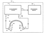
- FIG. 1 is a block diagram of an apparatus of the present invention.
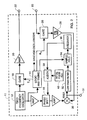
- FIG. 2 is a schematic diagram of one embodiment of a measuring device that can be used in the apparatus of the present invention.
- FIGS. 1 and 2 of the drawings in which like numerals refer to like features of the invention.
- apparatus 10 of the present invention comprises measurement device 11 .
- the measurement device can be configured as a CFPPLL described in commonly owned U.S. Pat. No. 5,214,955, the disclosure of which is herein incorporated by reference as if set forth in its entirety.
- the CFPPLL is shown in FIG. 2 and is briefly described in the ensuing description in order to facilitate understanding of the present invention.
- the CFPPLL is configured to operate in the “pitch-catch” mode which is described in the aforementioned U.S. Pat. No. 5,214,955.
- the measurement device 11 might comprise a variable frequency pulsed phase-locked loop (“VFPPLL”), for example as described in the article by Yost, et al., Fundamental Aspects of Pulse Phase-locked Loop Technology-based Methods for Measurement of Ultrasonic Velocity , J. Acoust. Soc. Am. 91, 1456-1468 (1992), which article is incorporated herein by reference as if set forth in its entirety.
- VFPPLL variable frequency pulsed phase-locked loop
- the CFPPLL includes a fixed frequency oscillator 12 , such as a phase-stable synthesizer.
- the fixed frequency oscillator 12 sends its constant frequency output to three different blocks: the logic and timing circuit 14 , a buffer amplifier-phase shift circuit 16 , and a tone-burst formation gate 18 .
- the logic and timing circuit 14 uses this signal as a clock and counts down to determine the timing on its outputs. One output is the transmit or Tx gate to form the electrical tone burst.
- the logic and timing circuit 14 also contains a setting so that the operator can set the gate for as many cycles as is desired.
- the electrical tone burst is amplified by amplifier 20 and delivered to output 22 which can be connected to a transmit transducer which is described in the ensuing description (see FIG. 1).
- the electrical tone burst is converted to a bulk compressional wave and is introduced to the surface of the skull which produces a surface wave.
- the surface wave travels a predetermined distance along the skull and is received by a receive transducer which is described in the ensuing description.
- the signals received by the receive transducer are inputted into input 23 of measurement device 11 .
- a receive or Rx gate signal enables gate 26 to pass the received signal to preamplifier 28 .
- the amplified received signal then proceeds to a mixer 30 where the amplified received signal is phase-compared to the reference signal provided from the fixed frequency oscillator 12 . Unless these two signals are at quadrature, a voltage level, which constitutes an error signal, is generated by the mixer 30 and passed to output 31 and a low-pass filter 32 .
- the output of low-pass filter 32 is inputted into a sample and hold 34 , which is activated by the logic and timing circuit 14 .
- the sample and hold 34 holds the level of voltage until the next pulse-echo cycle (P-Ec).
- P-Ec pulse-echo cycle
- This output voltage is fed to an integrator circuit 36 whose voltage output is delivered to the phase shift circuit 16 after passing through an adder circuit 38 .
- the adder circuit 38 also receives a voltage adjustment from an initial phase adjustment 40 , which may be manually operated by turning a dial. In at least one embodiment, during initial set up the operator thus changes the voltage output of the mixer 30 , if necessary, by using the phase adjuster and adder circuit until the sample and hold voltage output is zero, which occurs at quadrature of the echo and the signal from the main frequency oscillator.
- any change in the acoustic parameters of the surface wave propagation path defined by the skull of a patient (and the location of the transmit and receive transducers) will result in a change in the quadrature condition by an alteration in the voltage to the phase-shift circuit.
- One way to quantify a phase is to observe the voltage applied to the phase shifter 16 .
- a known, adjustable phase shifter such as a calibrated line stretcher (not shown, but described in U.S. Pat. No. 5,214,955, the disclosure of which patent is herein incorporated by reference) and adjusting until the same input voltage to the phase shifter is obtained.
- measurement device 11 is configured as the electronic apparatus described in commonly owned U.S. Pat. No. 5,617,873, the disclosure of which is herein incorporated by reference, and indicated by numeral 30 therein.
- apparatus 10 further includes mounting strut 50 .
- Mounting strut 50 comprises center section 52 and movable end portions 54 and 56 . End portions 54 and 56 are pivotally connected to center section 52 by pivot pins 58 .
- Mounting strut 50 further includes transmit and receive angle blocks 60 and 62 , respectively, that are attached to end portions 54 and 56 , respectively. Transmit and receive angle blocks 60 and 62 have surfaces 64 and 66 , respectively, that are configured for contact with a patient's head.
- mounting strut 50 is configured to have a predetermined degree of elasticity so as to provide firm contact between surfaces 64 , 66 , and the head of a patient.
- mounting strut 50 is configured so that end portions 54 and 56 are urged inward towards the patient's head so as to facilitate firm contact between surfaces 64 , 66 , and the head of a patient.
- mounting strut 50 is configured so that center section 52 is comprised of two portions that are slidably engaged with each other so that the overall length of center section 50 can be adjusted so as to accommodate skulls of varying sizes.
- center section 52 is comprised of two portions that are slidably engaged with each other so that the overall length of center section 50 can be adjusted so as to accommodate skulls of varying sizes.
- Such a feature can be used to vary the length of the propagation path over the patient's skull thus enabling the surface wave to be launched over a relatively small propagation path, for example, the patient's forehead or any other appropriate segment of the patient's skull.
- apparatus 10 further comprises transmit and receive transducers 70 and 72 that are attached to transmit and receive angle blocks 60 and 62 , respectively.
- Transmit transducer 70 is electrically connected to output 22 of measuring device 11 , for example, by wire or cable 74 .
- receive transducer 72 is electrically connected to input 23 of measuring device 11 , for example, by wire or cable 76 .
- Apparatus 10 can further include processing device 80 that receives the signals outputted at output 31 of measuring device 11 .
- Processing device 80 can implement measurement interpretive algorithms in order to generate a biological time constant which is used in the analysis of the data extracted from the signal outputted at output 31 of measuring device 11 .
- processing device 80 includes electronic components and circuitry such as microprocessors, timing circuitry, data storage devices (e.g. RAM, ROM, cache, etc.), filter circuits, and other processing circuits for effecting implementation of the aforementioned measurement interpretive algorithms.
- processor device 80 is configured as a computer that implements a computer program that effects generation of the aforesaid biological time constant.
- Measurement device 11 outputs an electrical tone burst through output 22 which is carried by wire 74 and is inputted into transmit transducer 70 .
- Transducer 70 converts the electrical tone burst into an ultrasonic bulk compressional wave.
- the ultrasonic bulk compressional wave passes through the transmit angle block 60 and is directed to the interface between surface 64 and the skin of the patient's skull.
- the ultrasonic bulk compressional wave passes into the subcutaneous tissue of the patient's skull at a predetermined angle, thereby producing a surface wave which travels along the skull.
- the surface wave traverses the skull along a propagation path and passes through the interface between the skin of the patient's skull and surface 66 of receive angle block 62 .
- the receive angle block 62 receives the surface wave and passes the surface wave to the receive transducer 72 .
- the angle at which the surface wave is received by the receive angle block is substantially the same as the predetermined angle described in the foregoing description.
- the receive angle block converts the surface wave into a bulk compressional wave.
- the receive transducer 72 converts the bulk compressional wave into an electrical waveform (i.e. an electrical tone burst).
- the electrical waveform is carried by wire or cable 76 to input 23 of measurement device 11 .
- Measuring device 11 measures the phase of the electrical waveform outputted by receive transducer 72 with respect to a reference signal in order to determine the change in phase between the two signals. Measuring device 11 outputs a signal at output 31 which contains data that indicates phase difference.
- the signal outputted at output 31 is inputted into processing device 80 which implements the measurement interpretive algorithms that determine the changes in circumferential expansion, or contraction, of the patient's skull due to changes in ICP.
- This circumferential expansion or contraction for example, can be calculated either in the form of total skull circumference change or in reference to changes in a specific circumferential arc portion of the skull. These determined circumferential changes can then be utilized to determine changes in ICP.
Abstract
A method and apparatus for measuring changes in intracranial pressure (ICP) utilizing the variation of the surface wave propagation parameters of the patient's skull to determine the change in ICP. In one embodiment, the method comprises the steps of transmitting an ultrasonic bulk compressional wave onto the surface of the skull at a predetermined angle with respect to the skull so as to produce a surface wave, receiving the surface wave at an angle with respect to the skull which is substantially the same as the predetermined angle and at a location that is a predetermined distance from where the ultrasonic bulk compressional wave was transmitted upon the skull, determining the retardation or advancement in phase of the received surface wave with respect to a reference phase, and processing the determined retardation or advancement in phase to determine circumferential expansion or contraction of the skull and utilizing the determined circumferential change to determine the change in intracranial pressure.
Description
- [0001] The invention described herein was made by employees of the United States Government and may be used by or for the Government for governmental purposes without the payment of any royalties thereon or therefor.
- 1. Technical Field of the Invention
- The present invention relates broadly to the field of apparatuses and methods for determining changes in intracranial pressure (“ICP”) by measuring the effects of these changes on a patient's skull.
- 2. Related Art and Problem to be Solved
- Monitoring circumferential expansion of the patient's skull due to changes in ICP is of significant diagnostic and post-operative importance for patients with cranial injuries, pathologies, or other conditions that may affect the pressure of the subarachnoidal fluid around the brain, and for patients who have undergone brain surgery.
- Known art methods and techniques for measuring changes in circumferential expansion of the patient's skull due to changes in ICP frequently involve launching an ultrasonic bulk compressional wave through the cranium. This technique can require that the position of the transducer be essentially absolutely stable, relative to the patient's skull, during data acquisition. However, one significant problem with the aforesaid known art method is the difficulty in keeping the transducers immobile relative to the patient's skull for long periods of time. Thus, inaccurate or inconclusive data may result due to transducer movement.
- It is an object of the present invention to provide a non-invasive method and apparatus for determining changes in ICP in a manner which does not require the transmission of a wave through the cranium.
- It is another object of the present invention to provide a new method and apparatus for determining changes in ICP by measuring changes in circumferential expansion or contraction of the patient's skull.
- It is another object of the present invention to provide a method and apparatus for determining changes in ICP, that provides substantially absolute stability of the transducer, relative to the patient's skull, during data acquisition.
- Other objects and advantages of the present invention will in part be obvious and will in part be apparent from the specification.
- The apparatus and method of the present invention use the variation of the surface wave propagation parameters of the patient's skull to determine the change in ICP.
- In accordance with one embodiment of the invention, the apparatus comprises a measuring device, transmit and receive transducers, and transmit and receive angle blocks wherein the transmit and receive transducers are mounted to the transmit and receive angle blocks, respectively. The transmit and receive angle blocks each have surfaces that are configured to contact the skull. The apparatus further includes a mounting strut to which the transmit and receive angle blocks are movably attached. The mounting strut is adjustable in overall length so as to accommodate skulls of varying sizes, and to provide stability to the transducers.
- In one embodiment, the measuring device is configured as a constant frequency pulsed phase-locked loop (“CFPPLL”) measuring device.
- The mounting strut can be adjusted on the skull so that the surface wave can be launched over a relatively small propagation path, for example, so the surface wave can travel across the forehead, or across a section of the skull containing a suture, or any other appropriate segment of the skull. Further, it is within the scope of the present invention that multiple pairs of tranducers (and angle blocks) could be used to launch (and receive) multiple surface waves over more than one propagation path. In this way, a differential comparison could then be made between the measured changes in ICP relative to each path. However, in at least one embodiment, each path may need to be calibrated separately and/or have different measurement interpretive algoritluns associated therewith (see below).
- In at least one embodiment, the measuring device generates an electrical tone burst which is inputted into the transmit transducer. The transmit transducer converts the electrical tone burst into a sound wave, such as an ultrasound bulk compressional wave that passes through the transmit angle block. The bulk compressional wave is then emitted into the skin and subcutaneous tissue that surrounds the skull at a predetermined angle so as to create a surface wave upon the skull. The surface wave travels over a propagation path and through the tissue that contacts the receive angle block. The receive angle block receives the surface wave at an angle that is generally the same as the aforementioned predetermined angle. The receive angle block converts the surface wave into an ultrasonic bulk compressional wave which is then received by the receive transducer. The receive transducer converts the ultrasonic bulk compressional wave back into an electrical tone burst which is inputted into the measurement device.
- The transmit and receive transducers could take various forms, for example: piezoelectric, magnetostrictive, or electrodynamic. Moreover, bone is mildly piezoelectric, therefore, in another possible embodiment, one could induce and detect a surface wave with electromagnetic transducers and essentially avoid potential problems with skin tissue perfusion variability.
- In at least one embodiment, the measurement device compares the phase of the electrical tone burst outputted by the receive transducer to a reference phase in order to determine if there is a difference in phase. As the skull responds to the changes in intracranial pressure, the velocity of the surface wave changes thereby resulting in retardation or advancement of the phase of the surface wave received by the receive angle block. Thus, the measurement device determines whether there has been any phase retardation or advancement. The measurement device outputs a data signal that represents the measured phase change.
- It is within the scope of the present invention that a variety of surface waves could be propagated on the skull. Examples of these surface waves may include, Rayleigh, Rayleigh-type, Generalized Rayleigh, Leaky (or psuedo-), Bleustein-Gulynev, Shear Horizontal, Lamb, Generalized Lamb, Love, and Stoneley waves. Additionally, as used herein, the term “sound wave” is used to refer to the propogation of a disturbance, resultant from the disturbing of substantially any medium.
- The apparatus of the present invention can further include a processing device that receives the data signal outputted by the measurement device and performs measurement interpretative algorithms on the data signal in order to determine the degree of circumferential expansion (or contraction) of the skull due to changes in ICP. This degree of circumferential expansion (or contraction) can be determined as a change to the total circumference of the skull or as a change to a circumferential arc portion of the skull.
- In at least one embodiment, the measurement interpretive algorithms can implement a biological time constant (for example, representing pulse rate, respiration, etc.) during interpretation of the data contained in the data signal outputted by the measuring device. In one embodiment, the processing device can be realized by a computer program that is configured to provide functions as filtering, integrating, averaging, etc. In another embodiment, the processing device is configured with electronic components that can provide the aforesaid functions.
- The features of the invention believed to be novel and the elements characteristic of the invention are set forth with particularity in the appended claims. The figures are for illustration purposes only and are not drawn to scale. The invention itself, however, both as to organization and method of operation, may best be understood by reference to the detailed description which follows taken in conjunction with the accompanying drawings in which:
- FIG. 1 is a block diagram of an apparatus of the present invention; and
- FIG. 2 is a schematic diagram of one embodiment of a measuring device that can be used in the apparatus of the present invention.
- In describing the embodiments of the present invention, reference will be made herein to FIGS. 1 and 2 of the drawings in which like numerals refer to like features of the invention.
- Referring to FIG. 1, there is shown
apparatus 10 of the present invention.Apparatus 10 comprisesmeasurement device 11. In one embodiment, the measurement device can be configured as a CFPPLL described in commonly owned U.S. Pat. No. 5,214,955, the disclosure of which is herein incorporated by reference as if set forth in its entirety. The CFPPLL is shown in FIG. 2 and is briefly described in the ensuing description in order to facilitate understanding of the present invention. The CFPPLL is configured to operate in the “pitch-catch” mode which is described in the aforementioned U.S. Pat. No. 5,214,955. In another embodiment, themeasurement device 11 might comprise a variable frequency pulsed phase-locked loop (“VFPPLL”), for example as described in the article by Yost, et al., Fundamental Aspects of Pulse Phase-locked Loop Technology-based Methods for Measurement of Ultrasonic Velocity, J. Acoust. Soc. Am. 91, 1456-1468 (1992), which article is incorporated herein by reference as if set forth in its entirety. - As shown in FIG. 2, the CFPPLL includes a fixed
frequency oscillator 12, such as a phase-stable synthesizer. The fixedfrequency oscillator 12 sends its constant frequency output to three different blocks: the logic andtiming circuit 14, a buffer amplifier-phase shift circuit 16, and a tone-burstformation gate 18. The logic andtiming circuit 14 uses this signal as a clock and counts down to determine the timing on its outputs. One output is the transmit or Tx gate to form the electrical tone burst. The logic andtiming circuit 14 also contains a setting so that the operator can set the gate for as many cycles as is desired. - The electrical tone burst is amplified by
amplifier 20 and delivered tooutput 22 which can be connected to a transmit transducer which is described in the ensuing description (see FIG. 1). As will be described in the ensuing description, after the electrical tone burst is received by the transmit transducer, the electrical tone burst is converted to a bulk compressional wave and is introduced to the surface of the skull which produces a surface wave. The surface wave travels a predetermined distance along the skull and is received by a receive transducer which is described in the ensuing description. The signals received by the receive transducer are inputted intoinput 23 ofmeasurement device 11. A receive or Rx gate signal enablesgate 26 to pass the received signal topreamplifier 28. The amplified received signal then proceeds to amixer 30 where the amplified received signal is phase-compared to the reference signal provided from the fixedfrequency oscillator 12. Unless these two signals are at quadrature, a voltage level, which constitutes an error signal, is generated by themixer 30 and passed tooutput 31 and a low-pass filter 32. The output of low-pass filter 32 is inputted into a sample and hold 34, which is activated by the logic andtiming circuit 14. The sample and hold 34 holds the level of voltage until the next pulse-echo cycle (P-Ec). Thus, the sample and hold output is updated at each P-Ec. This output voltage is fed to anintegrator circuit 36 whose voltage output is delivered to thephase shift circuit 16 after passing through anadder circuit 38. Theadder circuit 38 also receives a voltage adjustment from aninitial phase adjustment 40, which may be manually operated by turning a dial. In at least one embodiment, during initial set up the operator thus changes the voltage output of themixer 30, if necessary, by using the phase adjuster and adder circuit until the sample and hold voltage output is zero, which occurs at quadrature of the echo and the signal from the main frequency oscillator. - Thus, any change in the acoustic parameters of the surface wave propagation path defined by the skull of a patient (and the location of the transmit and receive transducers) will result in a change in the quadrature condition by an alteration in the voltage to the phase-shift circuit. One way to quantify a phase is to observe the voltage applied to the
phase shifter 16. There are a variety of ways in which to quantify the phase shift. In order to measure changes in velocity, the results must be measured in terms of the phase shift caused by changes in the traversal time of the acoustical signal as the acoustic signal travels along the propagation path defined by the skull. This is affected by change in phase in either the electrical or acoustical parameters. One can use this fact to calibrate by either calibrating the phase shift circuit against input voltage and reading the input voltage changes, or inserting a known, adjustable phase shifter, such as a calibrated line stretcher (not shown, but described in U.S. Pat. No. 5,214,955, the disclosure of which patent is herein incorporated by reference) and adjusting until the same input voltage to the phase shifter is obtained. - In at least one alternate embodiment,
measurement device 11 is configured as the electronic apparatus described in commonly owned U.S. Pat. No. 5,617,873, the disclosure of which is herein incorporated by reference, and indicated by numeral 30 therein. - Referring to FIG. 1 herein,
apparatus 10 further includes mountingstrut 50. Mountingstrut 50 comprisescenter section 52 andmovable end portions End portions section 52 by pivot pins 58. Mountingstrut 50 further includes transmit and receive angle blocks 60 and 62, respectively, that are attached to endportions surfaces strut 50 is configured to have a predetermined degree of elasticity so as to provide firm contact betweensurfaces strut 50 is configured so thatend portions surfaces - In another embodiment, mounting
strut 50 is configured so thatcenter section 52 is comprised of two portions that are slidably engaged with each other so that the overall length ofcenter section 50 can be adjusted so as to accommodate skulls of varying sizes. Such a feature can be used to vary the length of the propagation path over the patient's skull thus enabling the surface wave to be launched over a relatively small propagation path, for example, the patient's forehead or any other appropriate segment of the patient's skull. - Referring to FIG. 1,
apparatus 10 further comprises transmit and receivetransducers transducer 70 is electrically connected tooutput 22 of measuringdevice 11, for example, by wire orcable 74. Similarly, receivetransducer 72 is electrically connected to input 23 of measuringdevice 11, for example, by wire orcable 76. -
Apparatus 10 can further includeprocessing device 80 that receives the signals outputted atoutput 31 of measuringdevice 11.Processing device 80 can implement measurement interpretive algorithms in order to generate a biological time constant which is used in the analysis of the data extracted from the signal outputted atoutput 31 of measuringdevice 11. In one embodiment,processing device 80 includes electronic components and circuitry such as microprocessors, timing circuitry, data storage devices (e.g. RAM, ROM, cache, etc.), filter circuits, and other processing circuits for effecting implementation of the aforementioned measurement interpretive algorithms. In another embodiment,processor device 80 is configured as a computer that implements a computer program that effects generation of the aforesaid biological time constant. - Operation
- Referring to FIG. 1, one possible mode of operation is as follows.
Measurement device 11 outputs an electrical tone burst throughoutput 22 which is carried bywire 74 and is inputted into transmittransducer 70.Transducer 70 converts the electrical tone burst into an ultrasonic bulk compressional wave. The ultrasonic bulk compressional wave passes through the transmitangle block 60 and is directed to the interface betweensurface 64 and the skin of the patient's skull. The ultrasonic bulk compressional wave passes into the subcutaneous tissue of the patient's skull at a predetermined angle, thereby producing a surface wave which travels along the skull. The surface wave traverses the skull along a propagation path and passes through the interface between the skin of the patient's skull andsurface 66 of receiveangle block 62. The receiveangle block 62 receives the surface wave and passes the surface wave to the receivetransducer 72. The angle at which the surface wave is received by the receive angle block is substantially the same as the predetermined angle described in the foregoing description. The receive angle block converts the surface wave into a bulk compressional wave. The receivetransducer 72 converts the bulk compressional wave into an electrical waveform (i.e. an electrical tone burst). The electrical waveform is carried by wire orcable 76 to input 23 ofmeasurement device 11. - As the patient's skull responds to ICP, the velocity of the surface wave changes thereby causing retardation or advancement of the phase of the received surface wave. Measuring
device 11 measures the phase of the electrical waveform outputted by receivetransducer 72 with respect to a reference signal in order to determine the change in phase between the two signals. Measuringdevice 11 outputs a signal atoutput 31 which contains data that indicates phase difference. The signal outputted atoutput 31 is inputted intoprocessing device 80 which implements the measurement interpretive algorithms that determine the changes in circumferential expansion, or contraction, of the patient's skull due to changes in ICP. This circumferential expansion or contraction, for example, can be calculated either in the form of total skull circumference change or in reference to changes in a specific circumferential arc portion of the skull. These determined circumferential changes can then be utilized to determine changes in ICP. - The principles, embodiments, and modes of operation of the present invention have been described in the foregoing specification. The invention which is intended to be protected herein should not, however, be construed as limited to the particular forms disclosed, as these are to be regarded as illustrative rather than restrictive. Variations or changes may be made by those skilled in the art without departing from the spirit of the invention. Accordingly, the foregoing detailed description should be considered exemplary in nature and not limited to the scope and spirit of the invention as set forth in the attached claims.
- Thus, having described the invention, what is claimed is:
Claims (31)
1. A method for determining changes in intracranial pressure within a patient's skull comprising:
transmitting a sound wave onto the surface of the skull so as to produce a surface wave;
receiving the surface wave at a location that is a predetermined distance from where the sound wave was transmitted upon the skull;
determining the change in phase of the received surface wave with respect to a reference phase; and
processing the determined change in phase to determine a change in intracranial pressure.
2. The method according to claim 1 wherein the step of processing the determined changes comprises the step of determining a change in the circumference, or a circumferential arc, of the skull.
3. The method according to claim 1 wherein:
the step of transmitting a sound wave comprises transmitting the sound wave at a predetermined angle with respect to the skull; and
the step of receiving the surface wave comprises receiving the surface wave at an angle with respect to the skull which is substantially the same as the predetermined angle.
4. The method according to claim 1 wherein the step of transmitting a sound wave onto the surface of the skull comprises transmitting an ultrasonic bulk compressional wave onto the surface of the skull so as to produce the surface wave.
5. The method according to claim 1 further comprising the step of generating an electrical tone burst, and wherein the transmitting step further comprises the step of converting the electrical tone burst into the sound wave.
6. The method according to claim 1 wherein the receiving step comprises the step of converting the received surface wave into an electrical waveform.
7. The method according to claim 5 wherein the step of determining the change in phase of the received surface wave comprises the step of determining the change in phase of the electrical waveform with respect to a reference phase.
8. The method according to claim 1 further comprising the step of providing a measurement interpretation algorithm and wherein the processing step comprises the step of processing the determined change in phase using measurement interpretation algorithms to determine changes in circumferential expansion or contraction due to changes in intracranial pressure.
9. The method according to claim 1 wherein the steps of transmitting and receiving are performed at more than one location on the patient's skull.
10. An apparatus for determining changes in intracranial pressure in a patient's skull, comprising:
a transmitting device for generating a sound wave on the surface of the skull;
a receiving device for receiving the surface wave at a location that is a predetermined distance from where the sound wave was generated upon the skull;
a measuring device for determining the change in phase of the received surface wave with respect to a reference phase; and
a processing device for using the determined phase change to determine a change in intracranial pressure.
11. The apparatus according to claim 9 wherein the processing device is configured to determine circumferential expansion or contraction of the skull, wherein the circumferential expansion or contraction of the skull is determined as at least one of:
a) a total circumference change, or
b) a circumferential arc change.
12. The apparatus according to claim 10 wherein:
the transmitting device is configured and disposed for transmitting the sound wave at a predetermined angle with respect to the skull so as to generate the surface wave; and
the receiving device is configured and disposed for receiving the surface wave at an angle with respect to the skull which is substantially the same as the predetermined angle.
13. The apparatus according to claim 10 wherein the transmitting device is for transmitting an ultrasonic bulk compressional wave onto the surface of the skull at the predetermined angle with respect to the skull so as to generate the surface wave.
14. The apparatus according to claim 10 wherein the measuring device is configured to include circuitry for generating an electrical tone burst for input into the transmitting device.
15. The apparatus according to claim 14 wherein the transmitting device comprises a transducer having an input for receiving the electrical tone burst and converting it into an ultrasonic bulk compressional wave.
16. The apparatus according to claim 15 wherein the transmitting device further includes a transmit angle block having a surface that contacts the skull, the transducer being mounted to the transmit angle block.
17. The apparatus according to claim 10 wherein the receiving device comprises a receive transducer having an input for receiving the surface wave and converting the surface wave into an electrical waveform.
18. The apparatus according to claim 17 wherein the receiving device further includes a receive angle block having a surface that contacts the skull, the receive transducer being mounted to the receive angle block.
19. The apparatus according to claim 17 wherein the measuring device is configured to compare the phase of the electrical waveform to the reference phase to determine the phase difference.
20. The apparatus according to claim 10 wherein the processing device include means for implementing measurement interpretative algorithms for using the determined phase change to determine circumferential expansion resulting from a change in intracranial pressure.
21. The apparatus according to claim 10 further comprising a mounting strut, the transmitting and receiving devices being movably attached to the mounting strut.
22. An apparatus for determining changes in intracranial pressure, comprising:
means for transmitting a wave onto the surface of the skull so as to produce a surface wave;
means for receiving the surface wave a distance from where the wave was transmitted upon the skull;
means for determining the change in phase of the received surface wave with respect to a reference phase; and
means for processing the determined phase change to determine a change in intracranial pressure.
23. The apparatus according to claim 22 wherein the processing means comprises means for determining the circumferential expansion or contraction of the skull, wherein the circumferential expansion or contraction is determined as at least one of:
a) a total circumference change, or
b) a circumferential arc change
24. The apparatus according to claim 22 wherein:
the transmitting device is configured and disposed for transmitting the wave at a predetermined angle with respect to the skull so as to produce the surface wave; and
the receiving device is configured and disposed for receiving the surface wave at an angle with respect to the skull which is substantially the same as the predetermined angle.
25. The apparatus according to claim 22 wherein the means for transmitting a wave onto the surface of the skull comprises means for transmitting an ultrasonic bulk compressional wave onto the surface of the skull.
26. The apparatus according to claim 22 wherein the means for transmitting a wave onto the surface of the skull comprises means for transmitting at least two waves onto the surface of the skull to thereby produce at least two surface waves.
27. The apparatus according to claim 26 wherein the means for transmitting at least two waves onto the surface of the skull comprises at least two transmit transducers.
28. The apparatus according to claim 22 wherein the means for receiving the surface wave comprises means for receiving at least two surface waves.
29. The apparatus according to claim 28 wherein the means for receiving at least two surface waves comprises at least two receive transducers.
30. An apparatus for determining changes in intracranial pressure in a patient's skull, comprising:
a transmitting device for generating a wave on the surface of the skull;
a receiving device for receiving the surface wave;
a measuring device for determining the change in phase of the received surface wave with respect to a reference phase; and
a processing device to utilize the determined phase change to determine a change in intracranial pressure.
31. The apparatus according to claim 30 wherein the processing device is configured to determine the circumferential expansion or contraction of the skull, wherein the circumferential expansion or contraction is determined as at least one of:
a) a total circumference change, or
b) a circumferential arc change.
Priority Applications (3)
| Application Number | Priority Date | Filing Date | Title |
|---|---|---|---|
| US10/121,932 US6746410B2 (en) | 2002-04-04 | 2002-04-04 | Method and apparatus for determining changes in intracranial pressure utilizing measurement of the circumferential expansion or contraction of a patient's skull |
| AU2002367850A AU2002367850A1 (en) | 2002-04-04 | 2002-11-22 | Method and apparatus for determining changes in intracranial pressure utilizing measurement of the circumferential expansion or contraction of a patient's skull |
| PCT/US2002/037581 WO2003084394A1 (en) | 2002-04-04 | 2002-11-22 | Method and apparatus for determining changes in intracranial pressure utilizing measurement of the circumferential expansion or contraction of a patient's skull |
Applications Claiming Priority (1)
| Application Number | Priority Date | Filing Date | Title |
|---|---|---|---|
| US10/121,932 US6746410B2 (en) | 2002-04-04 | 2002-04-04 | Method and apparatus for determining changes in intracranial pressure utilizing measurement of the circumferential expansion or contraction of a patient's skull |
Publications (2)
| Publication Number | Publication Date |
|---|---|
| US20030191409A1 true US20030191409A1 (en) | 2003-10-09 |
| US6746410B2 US6746410B2 (en) | 2004-06-08 |
Family
ID=28674653
Family Applications (1)
| Application Number | Title | Priority Date | Filing Date |
|---|---|---|---|
| US10/121,932 Expired - Lifetime US6746410B2 (en) | 2002-04-04 | 2002-04-04 | Method and apparatus for determining changes in intracranial pressure utilizing measurement of the circumferential expansion or contraction of a patient's skull |
Country Status (3)
| Country | Link |
|---|---|
| US (1) | US6746410B2 (en) |
| AU (1) | AU2002367850A1 (en) |
| WO (1) | WO2003084394A1 (en) |
Cited By (15)
| Publication number | Priority date | Publication date | Assignee | Title |
|---|---|---|---|---|
| US6740048B2 (en) | 2002-04-08 | 2004-05-25 | The United States Of America As Represented By The Administrator Of The National Aeronautics And Space Administration | Non-invasive method of determining diastolic intracranial pressure |
| US6761695B2 (en) | 2002-03-07 | 2004-07-13 | The United States Of America As Represented By The Administrator Of The National Aeronautics And Space Administration | Method and apparatus for non-invasive measurement of changes in intracranial pressure |
| US6773407B2 (en) | 2002-04-08 | 2004-08-10 | The United States Of America As Represented By The Administrator Of The National Aeronautics And Space Administration | Non-invasive method of determining absolute intracranial pressure |
| EP1727469A2 (en) * | 2004-03-22 | 2006-12-06 | United States of America, represented by The Administrator of the National Aeronautics and Space Administration | Ultrasonic apparatus and method to assess compartment syndrome |
| WO2010019705A2 (en) * | 2008-08-12 | 2010-02-18 | The Regents Of The University Of California | Morphological clustering and analysis of intracranial pressure pulses (mocaip) |
| US20100049082A1 (en) * | 2006-04-05 | 2010-02-25 | The Regents Of The University Of California | Data mining system for noninvasive intracranial pressure assessment |
| WO2010151734A2 (en) * | 2009-06-26 | 2010-12-29 | Virginia Commonwealth University | Sensor for non-invasively monitoring intracranial pressure |
| WO2012046223A1 (en) * | 2010-10-08 | 2012-04-12 | Headsense Medical Ltd. | Apparatus and method for measuring intracranial pressure |
| CN102973260A (en) * | 2012-11-30 | 2013-03-20 | 中国人民解放军第三军医大学生物医学工程与医学影像学院 | Noncontact magnetic sensing-type intracranial pressure monitoring device |
| WO2013064740A1 (en) * | 2011-11-01 | 2013-05-10 | Oscare Medical Oy | A skeletal method and arrangement utilizing electromagnetic waves |
| US20150223722A1 (en) * | 2012-01-19 | 2015-08-13 | Cerebrotech Medical Systems, Inc. | Method for detecting and treating variations in fluid |
| US20150374292A1 (en) * | 2012-01-19 | 2015-12-31 | Cerebrotech Medical Systems, Inc. | Detection and analysis of spatially varying fluid levels using magnetic signals |
| WO2016036946A1 (en) * | 2014-09-03 | 2016-03-10 | Cerebrotech Medical Systems, Inc. | Detection and analysis of spatially varying fluid levels using magnetic signals |
| US10250979B2 (en) * | 2016-12-01 | 2019-04-02 | Council Of Scientific & Industrial Research | Electromagnetic acoustic transducer excitation source with programmable tone burst generator |
| US11357417B2 (en) | 2012-01-19 | 2022-06-14 | Cerebrotech Medical Systems, Inc. | Continuous autoregulation system |
Families Citing this family (9)
| Publication number | Priority date | Publication date | Assignee | Title |
|---|---|---|---|---|
| US7520862B2 (en) * | 2004-02-03 | 2009-04-21 | Neuro Diagnostic Devices, Inc. | Cerebral spinal fluid shunt evaluation system |
| US7381186B2 (en) * | 2004-08-02 | 2008-06-03 | The United States Of America As Represented By The Administrator Of The National Aeronautics And Space Administration | Method and apparatus to assess compartment syndrome |
| WO2006119511A2 (en) * | 2005-05-04 | 2006-11-09 | Luna Innovations, Incorporated | Ultrasonic method to determine bone parameters |
| US20070038060A1 (en) * | 2005-06-09 | 2007-02-15 | Cerwin Stephen A | Identifying and treating bodily tissues using electromagnetically induced, time-reversed, acoustic signals |
| US8277385B2 (en) | 2009-02-04 | 2012-10-02 | Advanced Brain Monitoring, Inc. | Method and apparatus for non-invasive assessment of hemodynamic and functional state of the brain |
| CN102429651B (en) * | 2011-08-15 | 2013-10-30 | 重庆大学 | Multi-parameter-based intracranial pressure noninvasive detection method and device |
| US9826934B2 (en) * | 2011-09-19 | 2017-11-28 | Braincare Desenvolvimento E Inovação Tecnológica Ltda | Non-invasive intracranial pressure system |
| CN102670252B (en) * | 2012-05-31 | 2013-11-27 | 重庆朗普科技有限公司 | Intracranial pressure non-invasive measuring method and system |
| US10390704B2 (en) | 2015-03-11 | 2019-08-27 | United States Of America As Represented By The Administrator Of Nasa | Systems and methods for measuring phase dynamics and other properties |
Citations (2)
| Publication number | Priority date | Publication date | Assignee | Title |
|---|---|---|---|---|
| US5074310A (en) * | 1990-07-31 | 1991-12-24 | Mick Edwin C | Method and apparatus for the measurement of intracranial pressure |
| US5251627A (en) * | 1991-06-27 | 1993-10-12 | Morris Donald E | Non-invasive measurement of eyeball pressure using vibration |
Family Cites Families (15)
| Publication number | Priority date | Publication date | Assignee | Title |
|---|---|---|---|---|
| JPS6382622A (en) | 1986-09-27 | 1988-04-13 | 日立建機株式会社 | Apparatus for recording intracranial pressure |
| JP3134121B2 (en) | 1989-10-11 | 2001-02-13 | バクスター インターナショナル インコーポレーテッド | Intracranial pressure monitor and drainage catheter assembly |
| US5214955A (en) | 1991-08-26 | 1993-06-01 | The United States Of America As Represented By The United States National Aeronautics And Space Administration | Constant frequency pulsed phase-locked loop measuring device |
| US5388583A (en) | 1993-09-01 | 1995-02-14 | Uab Vittamed | Method and apparatus for non-invasively deriving and indicating of dynamic characteristics of the human and animal intracranial media |
| US5617873A (en) | 1994-08-25 | 1997-04-08 | The United States Of America As Represented By The Administrator, Of The National Aeronautics And Space Administration | Non-invasive method and apparatus for monitoring intracranial pressure and pressure volume index in humans |
| US6117089A (en) | 1995-04-25 | 2000-09-12 | The Regents Of The University Of California | Method for noninvasive intracranial pressure measurement |
| US5951476A (en) | 1997-11-14 | 1999-09-14 | Beach; Kirk Watson | Method for detecting brain microhemorrhage |
| US6231509B1 (en) | 1997-12-05 | 2001-05-15 | Royce Johnson | Apparatus and method for monitoring intracranial pressure |
| WO2000032105A1 (en) | 1998-11-25 | 2000-06-08 | Ball Semiconductor, Inc. | Monitor for interventional procedures |
| WO2001054584A1 (en) | 1999-01-27 | 2001-08-02 | The Government Of The United States As Represented By The Administrator Of The National Aeronautics And Space Administration | Ultrasonic apparatus and technique to measure changes in intracranial pressure |
| AU4600700A (en) | 1999-05-10 | 2000-11-21 | Inta Medics Ltd. | Noninvasive monitoring of intracranial pressure |
| US6413227B1 (en) | 1999-12-02 | 2002-07-02 | The United States Of America As Represented By The Administrator Of The National Aeronautics And Space Administration | Method and apparatus for assessment of changes in intracranial pressure |
| US6761695B2 (en) | 2002-03-07 | 2004-07-13 | The United States Of America As Represented By The Administrator Of The National Aeronautics And Space Administration | Method and apparatus for non-invasive measurement of changes in intracranial pressure |
| US6773407B2 (en) | 2002-04-08 | 2004-08-10 | The United States Of America As Represented By The Administrator Of The National Aeronautics And Space Administration | Non-invasive method of determining absolute intracranial pressure |
| US6740048B2 (en) | 2002-04-08 | 2004-05-25 | The United States Of America As Represented By The Administrator Of The National Aeronautics And Space Administration | Non-invasive method of determining diastolic intracranial pressure |
-
2002
- 2002-04-04 US US10/121,932 patent/US6746410B2/en not_active Expired - Lifetime
- 2002-11-22 AU AU2002367850A patent/AU2002367850A1/en not_active Abandoned
- 2002-11-22 WO PCT/US2002/037581 patent/WO2003084394A1/en not_active Application Discontinuation
Patent Citations (2)
| Publication number | Priority date | Publication date | Assignee | Title |
|---|---|---|---|---|
| US5074310A (en) * | 1990-07-31 | 1991-12-24 | Mick Edwin C | Method and apparatus for the measurement of intracranial pressure |
| US5251627A (en) * | 1991-06-27 | 1993-10-12 | Morris Donald E | Non-invasive measurement of eyeball pressure using vibration |
Cited By (33)
| Publication number | Priority date | Publication date | Assignee | Title |
|---|---|---|---|---|
| US6761695B2 (en) | 2002-03-07 | 2004-07-13 | The United States Of America As Represented By The Administrator Of The National Aeronautics And Space Administration | Method and apparatus for non-invasive measurement of changes in intracranial pressure |
| US6773407B2 (en) | 2002-04-08 | 2004-08-10 | The United States Of America As Represented By The Administrator Of The National Aeronautics And Space Administration | Non-invasive method of determining absolute intracranial pressure |
| US6740048B2 (en) | 2002-04-08 | 2004-05-25 | The United States Of America As Represented By The Administrator Of The National Aeronautics And Space Administration | Non-invasive method of determining diastolic intracranial pressure |
| EP1727469A2 (en) * | 2004-03-22 | 2006-12-06 | United States of America, represented by The Administrator of the National Aeronautics and Space Administration | Ultrasonic apparatus and method to assess compartment syndrome |
| EP1727469A4 (en) * | 2004-03-22 | 2007-09-05 | Nasa | Ultrasonic apparatus and method to assess compartment syndrome |
| US7491169B2 (en) | 2004-03-22 | 2009-02-17 | The United States Of America As Represented By The Administrator Of The National Aeronautics And Space Administration | Ultrasonic apparatus and method to assess compartment syndrome |
| US8821408B2 (en) * | 2006-04-05 | 2014-09-02 | The Regents Of The University Of California | Data mining system for noninvasive intracranial pressure assessment |
| US20100049082A1 (en) * | 2006-04-05 | 2010-02-25 | The Regents Of The University Of California | Data mining system for noninvasive intracranial pressure assessment |
| WO2010019705A2 (en) * | 2008-08-12 | 2010-02-18 | The Regents Of The University Of California | Morphological clustering and analysis of intracranial pressure pulses (mocaip) |
| US20110201961A1 (en) * | 2008-08-12 | 2011-08-18 | The Regents Of The University Of California | Morphological clustering and analysis of intracranial pressure pulses (mocaip) |
| WO2010019705A3 (en) * | 2008-08-12 | 2010-06-17 | The Regents Of The University Of California | Morphological clustering and analysis of intracranial pressure pulses (mocaip) |
| WO2010151734A2 (en) * | 2009-06-26 | 2010-12-29 | Virginia Commonwealth University | Sensor for non-invasively monitoring intracranial pressure |
| WO2010151734A3 (en) * | 2009-06-26 | 2011-04-14 | Virginia Commonwealth University | Sensor for non-invasively monitoring intracranial pressure |
| JP2013538664A (en) * | 2010-10-08 | 2013-10-17 | ヘッドセンス メディカル リミテッド | Apparatus and method for measuring intracranial pressure |
| WO2012046223A1 (en) * | 2010-10-08 | 2012-04-12 | Headsense Medical Ltd. | Apparatus and method for measuring intracranial pressure |
| CN103260504A (en) * | 2010-10-08 | 2013-08-21 | 海达星医疗有限公司 | Apparatus and method for measuring intracranial pressure |
| US9801608B2 (en) | 2010-10-08 | 2017-10-31 | Headsense Medical Ltd. | Apparatus and method for measuring intracranial pressure |
| US9138154B2 (en) | 2010-10-08 | 2015-09-22 | Headsense Medical Ltd. | Apparatus and method for measuring intracranial pressure |
| WO2013064740A1 (en) * | 2011-11-01 | 2013-05-10 | Oscare Medical Oy | A skeletal method and arrangement utilizing electromagnetic waves |
| CN103906474A (en) * | 2011-11-01 | 2014-07-02 | 骨治医疗公司 | A skeletal method and arrangement utilizing electromagnetic waves |
| US10751026B2 (en) | 2011-11-01 | 2020-08-25 | Oscare Medical Oy | Skeletal method and arrangement utilizing electromagnetic waves |
| US20150223722A1 (en) * | 2012-01-19 | 2015-08-13 | Cerebrotech Medical Systems, Inc. | Method for detecting and treating variations in fluid |
| US20150374292A1 (en) * | 2012-01-19 | 2015-12-31 | Cerebrotech Medical Systems, Inc. | Detection and analysis of spatially varying fluid levels using magnetic signals |
| US11357417B2 (en) | 2012-01-19 | 2022-06-14 | Cerebrotech Medical Systems, Inc. | Continuous autoregulation system |
| US11723597B2 (en) | 2012-01-19 | 2023-08-15 | Cerebrotech Medical Systems, Inc. | Detection and analysis of spatially varying fluid levels using magnetic signals |
| US10335054B2 (en) * | 2012-01-19 | 2019-07-02 | Cerebrotech Medical Systems, Inc. | Method for detecting fluid in cranuim via time varying magnetic field phase shifts |
| US11612331B2 (en) | 2012-01-19 | 2023-03-28 | Cerebrotech Medical Systems, Inc. | Headset device for detecting fluid in cranium via time varying magnetic field phase shifts and harmonics of fundamental frequencies |
| US10743815B2 (en) * | 2012-01-19 | 2020-08-18 | Cerebrotech Medical Systems, Inc. | Detection and analysis of spatially varying fluid levels using magnetic signals |
| US11166671B2 (en) | 2012-01-19 | 2021-11-09 | Cerebrotech Medical Systems, Inc. | Differentiation of fluid volume change |
| CN102973260A (en) * | 2012-11-30 | 2013-03-20 | 中国人民解放军第三军医大学生物医学工程与医学影像学院 | Noncontact magnetic sensing-type intracranial pressure monitoring device |
| WO2016036946A1 (en) * | 2014-09-03 | 2016-03-10 | Cerebrotech Medical Systems, Inc. | Detection and analysis of spatially varying fluid levels using magnetic signals |
| AU2015311843B2 (en) * | 2014-09-03 | 2020-05-21 | Cerebrotech Medical Systems, Inc. | Detection and analysis of spatially varying fluid levels using magnetic signals |
| US10250979B2 (en) * | 2016-12-01 | 2019-04-02 | Council Of Scientific & Industrial Research | Electromagnetic acoustic transducer excitation source with programmable tone burst generator |
Also Published As
| Publication number | Publication date |
|---|---|
| WO2003084394A1 (en) | 2003-10-16 |
| AU2002367850A1 (en) | 2003-10-20 |
| US6746410B2 (en) | 2004-06-08 |
Similar Documents
| Publication | Publication Date | Title |
|---|---|---|
| US6746410B2 (en) | Method and apparatus for determining changes in intracranial pressure utilizing measurement of the circumferential expansion or contraction of a patient's skull | |
| US7601120B2 (en) | Method and device for the non-invasive assessment of bones | |
| US5617873A (en) | Non-invasive method and apparatus for monitoring intracranial pressure and pressure volume index in humans | |
| US6475147B1 (en) | Ultrasonic apparatus and technique to measure changes in intracranial pressure | |
| US6413227B1 (en) | Method and apparatus for assessment of changes in intracranial pressure | |
| US10835202B2 (en) | System and method for analyzing tissue using shear waves | |
| JP2018538094A (en) | Method and apparatus for detecting viscoelastic parameters of viscoelastic medium | |
| JPS5855850A (en) | System for measuring medium characteristic with reflected ultrasonic wave | |
| US6322507B1 (en) | Ultrasonic apparatus and method for evaluation of bone tissue | |
| US6854331B2 (en) | Substance characteristic measuring method and substance characteristic measuring instrument | |
| US11185232B2 (en) | Methods for measuring phase dynamics and other properties | |
| US20170086796A1 (en) | Ultrasonic reception signal correction device, ultrasonic measurement apparatus, and ultrasonic reception signal correction method | |
| JP2629734B2 (en) | Ultrasonic object inspection equipment | |
| Yost et al. | Method and apparatus for determining changes in intracranial pressure utilizing measurement of the circumferential expansion or contraction of a patient's skull | |
| JP2669204B2 (en) | Exploration equipment | |
| Yoshizawa et al. | Transducer vibration method for interference-based reflection-type in vivo measurement for acoustic impedance of bone | |
| von Krger et al. | Doppler ultrasound tracking instrument for monitoring blood flow velocity | |
| JPH0548130B2 (en) | ||
| RU2654006C1 (en) | Device of acoustic diagnostics with frequency scanning of bone tissue | |
| Cantrell et al. | Non-invasive method and apparatus for monitoring intracranial pressure and pressure volume index in humans | |
| Yost et al. | Method and apparatus for assessment of changes in intracranial pressure | |
| Yost et al. | Non-invasive method and apparatus for monitoring intracranial pressure and pressure volume index in humans | |
| JPH0339146A (en) | Ultrasonic measuring apparatus | |
| JPH0351757A (en) | Method and apparatus for measuring acoustic characteristic | |
| JPH05154113A (en) | Hardness measuring instrument for biotissue |
Legal Events
| Date | Code | Title | Description |
|---|---|---|---|
| AS | Assignment |
Owner name: NATIONAL AERONAUTICS AND SPACE ADMINISTRATION, DIS Free format text: ASSIGNMENT OF ASSIGNORS INTEREST;ASSIGNORS:YOST, WILLIAM T.;CANTRELL, JOHN H., JR.;REEL/FRAME:012810/0866 Effective date: 20020404 |
|
| STCF | Information on status: patent grant |
Free format text: PATENTED CASE |
|
| FPAY | Fee payment |
Year of fee payment: 4 |
|
| FPAY | Fee payment |
Year of fee payment: 8 |
|
| FPAY | Fee payment |
Year of fee payment: 12 |