US20030191425A1 - Blood treatment catheter and method - Google Patents
Blood treatment catheter and method Download PDFInfo
- Publication number
- US20030191425A1 US20030191425A1 US10/116,299 US11629902A US2003191425A1 US 20030191425 A1 US20030191425 A1 US 20030191425A1 US 11629902 A US11629902 A US 11629902A US 2003191425 A1 US2003191425 A1 US 2003191425A1
- Authority
- US
- United States
- Prior art keywords
- infusion
- catheter
- aspirating
- lumen
- port
- Prior art date
- Legal status (The legal status is an assumption and is not a legal conclusion. Google has not performed a legal analysis and makes no representation as to the accuracy of the status listed.)
- Granted
Links
Images


Classifications
-
- A—HUMAN NECESSITIES
- A61—MEDICAL OR VETERINARY SCIENCE; HYGIENE
- A61M—DEVICES FOR INTRODUCING MEDIA INTO, OR ONTO, THE BODY; DEVICES FOR TRANSDUCING BODY MEDIA OR FOR TAKING MEDIA FROM THE BODY; DEVICES FOR PRODUCING OR ENDING SLEEP OR STUPOR
- A61M25/00—Catheters; Hollow probes
- A61M25/0021—Catheters; Hollow probes characterised by the form of the tubing
- A61M25/0023—Catheters; Hollow probes characterised by the form of the tubing by the form of the lumen, e.g. cross-section, variable diameter
- A61M25/0026—Multi-lumen catheters with stationary elements
- A61M25/0032—Multi-lumen catheters with stationary elements characterized by at least one unconventionally shaped lumen, e.g. polygons, ellipsoids, wedges or shapes comprising concave and convex parts
-
- A—HUMAN NECESSITIES
- A61—MEDICAL OR VETERINARY SCIENCE; HYGIENE
- A61M—DEVICES FOR INTRODUCING MEDIA INTO, OR ONTO, THE BODY; DEVICES FOR TRANSDUCING BODY MEDIA OR FOR TAKING MEDIA FROM THE BODY; DEVICES FOR PRODUCING OR ENDING SLEEP OR STUPOR
- A61M1/00—Suction or pumping devices for medical purposes; Devices for carrying-off, for treatment of, or for carrying-over, body-liquids; Drainage systems
- A61M1/36—Other treatment of blood in a by-pass of the natural circulatory system, e.g. temperature adaptation, irradiation ; Extra-corporeal blood circuits
- A61M1/3621—Extra-corporeal blood circuits
- A61M1/3653—Interfaces between patient blood circulation and extra-corporal blood circuit
- A61M1/3659—Cannulae pertaining to extracorporeal circulation
- A61M1/3661—Cannulae pertaining to extracorporeal circulation for haemodialysis
-
- A—HUMAN NECESSITIES
- A61—MEDICAL OR VETERINARY SCIENCE; HYGIENE
- A61M—DEVICES FOR INTRODUCING MEDIA INTO, OR ONTO, THE BODY; DEVICES FOR TRANSDUCING BODY MEDIA OR FOR TAKING MEDIA FROM THE BODY; DEVICES FOR PRODUCING OR ENDING SLEEP OR STUPOR
- A61M25/00—Catheters; Hollow probes
- A61M25/0067—Catheters; Hollow probes characterised by the distal end, e.g. tips
- A61M25/0068—Static characteristics of the catheter tip, e.g. shape, atraumatic tip, curved tip or tip structure
- A61M25/007—Side holes, e.g. their profiles or arrangements; Provisions to keep side holes unblocked
-
- A—HUMAN NECESSITIES
- A61—MEDICAL OR VETERINARY SCIENCE; HYGIENE
- A61M—DEVICES FOR INTRODUCING MEDIA INTO, OR ONTO, THE BODY; DEVICES FOR TRANSDUCING BODY MEDIA OR FOR TAKING MEDIA FROM THE BODY; DEVICES FOR PRODUCING OR ENDING SLEEP OR STUPOR
- A61M25/00—Catheters; Hollow probes
- A61M25/0021—Catheters; Hollow probes characterised by the form of the tubing
- A61M25/0023—Catheters; Hollow probes characterised by the form of the tubing by the form of the lumen, e.g. cross-section, variable diameter
- A61M25/0026—Multi-lumen catheters with stationary elements
- A61M25/003—Multi-lumen catheters with stationary elements characterized by features relating to least one lumen located at the distal part of the catheter, e.g. filters, plugs or valves
- A61M2025/0031—Multi-lumen catheters with stationary elements characterized by features relating to least one lumen located at the distal part of the catheter, e.g. filters, plugs or valves characterized by lumina for withdrawing or delivering, i.e. used for extracorporeal circuit treatment
Definitions
- This invention relates in general to blood treatment catheters and more particularly to a design for use in hemo-dialysis in which the occlusion of the distal ports due to fibrin buildup is substantially eliminated.
- Hemo-dialysis is the process of mass transfer, in which certain chemical substances, accumulated in the blood because of kidney failure, are transferred from the blood across a semi permeable dialysis membrane to a balanced salt solution.
- the efficiency of a hemo-dialysis procedure depends on the amount of blood brought into contact with the dialysis membrane.
- a flow of 250 milliliters of blood per minute under a pressure gradient of 100 millimeters of mercury is considered a minimum requirement for adequate dialysis.
- flow rate between 350 milliliters per minute and 400 milliliters per minute have become common.
- occlusive material At the place where the catheter is inserted into the patient, the body reacts by creating a sheath of material that includes fibrin and other materials that grow down the outer wall of the catheter from the point of insertion in the vein. This material is referred to herein as occlusive material. This occlusive material when it grows down to the site of ports, and most particularly the aspirating port, tends to block the ports rendering the catheter essentially useless.
- the catheter disclosed has both aspirating and infusion lumens.
- the tube carrying the aspirating lumen extends distally of the end of the tube defining the infusion lumen.
- the infusion lumen is substantially annular around the aspirating tube and has infusion ports that provide emission of fluid over substantially 360° as a jet like emission having a significant radial component.
- a nose of a built up zone on the outside of the aspirating tube, immediately adjacent to and distal of the exit port from the infusion lumen, provides a wall for the exit port to assure that the jet of fluid exits in a substantially radial direction.
- This jet of infusion fluid abrades the occlusion that tends to grow down these catheters from the point of insertion into the patient.
- the 360° infusion jet prevents such occlusive material not only from clogging the infusion port but also prevents further distal growth along the aspirating tube. This means that occlusion of the end of the aspirating tube by occluding material is avoided.
- occlusion or occlusive material refers to the well known coating that builds up on the exterior of these catheters. It starts at approximately the point where the catheter is inserted through the vein and builds down along the outside surface of the catheter. This occlusion build up is believed to be composed of a number of materials such as fibrin, and/or muscle cells and/or blood clot.
- This invention is addressed to a technique of preventing the occlusion build up from extending down over the end of the aspirating port or ports and causing the aspirating ports to block.
- FIGS. 3 through 6 contain a plurality of infusion exit ports.
- a design can be provided in which there is a single circumferential exit port.
- An essential feature is that there is a substantial 360° jet having a substantial radial component which serves to abrade and clear away occlusion that grows down the outer wall of the catheter.
- the aspirating port though shown as a single end port can be a plurality of circumferential ports and the term “port” is used to include the multiple port arrangement.
- port or “ports” or “port arrangement” in the specification and claims are used to include a single port and/or a set of ports, such as the ports 26 a of FIG. 3 and the ports 26 b of FIG. 5.
- FIG. 1 is a schematic illustration of the positioning of the hemo-dialysis catheter of this invention through the jugular vein.
- the catheter is inserted into the patient at point A and into the vein at point B.
- FIG. 2 is an elevation view of a catheter of this invention showing the infusion tube 18 and aspirating tube 20 combined at juncture 22 to form the main portion 24 of the catheter.
- Infusion ports 26 are at the distal end of the infusion lumen.
- Aspirating port 34 is at the distal end of the aspirating tube 20 .
- FIG. 3 is a larger scale elevation view of the zone around the distal infusion port of an embodiment of the FIG. 2 catheter having a plurality of angled infusion ports 26 a.
- FIG. 4 is a partial longitudinal sectional view through the FIG. 3 catheter portion.
- FIG. 5 is a larger scale elevation view of the zone around the distal infusion port of a second embodiment of the FIG. 2 catheter showing a plurality of arcuate circumferential ports 26 b.
- FIG. 6 is a partial longitudinal sectional view along the FIG. 5 catheter portion.
- FIG. 7 is a longitudinal sectional view of a further embodiment of the FIG. 2 catheter in which the infusion port 26 is substantially a 360° circumferential port.
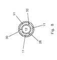
- FIG. 8 is a cross-sectional view along the plane 8 - 8 of FIG. 7 showing a three chamber section of the circumferential infusion lumen 11 immediately adjacent to the infusion port 26 .
- FIG. 9 is a schematic illustration of the infusion of filtered blood at the infusion ports of the infusion lumen.
- FIG. 9 illustrates the umbrella-like shape of the infusion 40 that results from the combined effect of the radial jet of filtered blood from the infusion ports 26 b and the downward flow of the patient's blood.
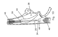
- FIG. 10 is a schematic illustration of blood flow into and from the catheter of this invention at the right atrium.
- FIG. 11 is an elevation view of a generic showing of the catheter of this invention. It is used to illustrate three embodiments of this invention which differ in the configuration of the infusion and aspirating lumens over the proximal 80 to 90 percent of the catheter that is between the juncture 22 and the infusion port 26 .
- FIGS. 12A, 12B, 12 C and 12 D are cross-sectional views along the planes A-A, B-B, C-C and D-D respectively, of FIG. 11 showing a presently preferred embodiment of this invention.
- These cross-sectional FIGS. show the transition from the semi-circular lumens 11 , 12 that exist along about eighty percent of the length of the catheter to the coaxial lumen arrangement immediately proximal of the infusion port 26 .
- FIG. 13 is a cross-sectional view along the plane A-A of FIG. 11 illustrating a further embodiment of this invention showing two shaped lumens 11 , 12 that exist over at least eighty percent of the length of the catheter.
- FIGS. 12C and 12D illustrate the transition of the FIG. 13 embodiment to the coaxial lumen arrangement immediately proximal of the infusion port 26 .
- FIG. 14 is a cross-sectional view along the plane A-A of FIG. 11 illustrating another embodiment of this invention in which the two lumens 11 , 12 are coaxial along the entire length from the juncture 22 to the infusion port 26 .
- the support web shown at FIG. 8 would be employed.
- FIG. 15 is a longitudinal sectional view through the connector 22 for the FIGS. 12 A- 12 D embodiment having the substantially semicircular lumens 11 and 12 .
- FIGS. 15A, 15B and 15 C are cross-sectional views along the planes A-A; B-B and C-C, respectively, of FIG. 15.
- FIG. 16 is a longitudinal sectional view of the connector for the FIG. 14 embodiment in which the lumens 11 , 12 are concentric from juncture 22 to infusion port 26 .
- the catheter 10 of this invention has an infusion lumen 11 and an aspirating lumen 12 .
- the distal end 16 of the aspirating lumen extends distally beyond the distal end 14 of the infusion lumen 11 .
- a standard infusion tube 18 and aspirating tube 20 are combined at a juncture 22 to provide a single tube 24 distal of the juncture 22 .
- the tube 24 contains infusion and aspirating lumens.
- the tube 24 is inserted into a patient at point A and passed into the jugular vein 25 at point B to be positioned at a desired location; often in the right atrium 38 as shown in FIG. 10.
- FIGS. 3 and 4 illustrate a presently preferred embodiment of this invention in which the infusion port set 26 is constituted by ten ports 26 a each having a major axis at an angle of approximately 45° to a circumferential line through the ports 26 a.
- each of the ports is approximately 50 mils (0.050 inches) by 20 mils (0.020 inches).
- These ports 26 a are at the distal end of the infusion lumen 11 .
- the infusion lumen 11 is a circumferential lumen around the aspirating lumen 12 in the zone that is immediately proximal of the infusion exit ports 26 a.
- An inner wall 28 defines the aspirating lumen 12 .
- the infusion lumen 11 is defined by the inner wall 28 and the outer wall 30 .
- Each port 26 a is a port in the outer wall 30 .
- the outer wall 30 merges into the inner wall 28 at the zone 36 . This provides a terminal wall for the infusion lumen 11 and assures that the infusing filtered blood is ejected through the set of ports 26 a in a substantially radial direction.
- FIGS. 5 and 6 illustrate a modified version of the FIGS. 3 and 4 embodiment.
- the distal infusion exit port 26 is composed of a plurality of circumferential ports 26 b. Each of these circumferential ports 26 b is approximately 20 mils (0.020 inches) wide.
- FIGS. 5 and 6 embodiment is the same as that of FIGS. 3 and 4 including the employment of the buildup section or nose at the zone 36 that serves to provide an end wall for the infusion lumen 11 and that provides an exit passageway that assures the infusing blood will exit in a substantially radial direction.
- FIGS. 7 and 8 illustrate a third embodiment of this invention in which the exit port 26 is a 360° circumferential port.
- a web design shown in FIG. 8, is employed at the exit port 26 .
- This web design involves three thin webs 32 which extend from the zone 36 proximally for about three millimeters in the embodiment shown.
- the web 32 supports are not required in the design shown in FIGS. 3 through 6.
- the outer wall 30 extends past the ports 26 a or 26 b to merge into the wall 28 of the aspirating lumen and thus does not require extra support.
- the design of this invention includes an embodiment in which the FIG. 8 web extends the length of the catheter from junction 22 to infusion exit port 26 . Such a design is not presently preferred because it provides a stiffer catheter than do the designs disclosed herein.
- the jet of fluid provided at the infusion port 26 serves to prevent buildup of occlusion distal of those ports. It is believed that a key factor is that the occlusion is physically abraded by the jet of fluid.
- the jet of filtered blood 40 exits from the ports 26 b in a radial direction and then as it joins the flow of patient's blood, becomes more axially oriented.
- the occlusion 42 builds up on the outer wall 30 and extends down to the ports 26 b where the abrading action of the jet of filtered blood prevents further growth of the occlusion 42 .
- the hemo-dialysis catheter is frequently placed in the right atrium 38 .
- a portion 44 is taken in at the aspirating port 34 to be processed and filtered.
- the filtered blood 40 is returned as a jet from the infusion lumen. This filtered blood 40 joins the blood flow 46 coming down from the superior vena cava into the right atrium to then be circulated throughout the body.
- FIG. 10 shows the catheter extending down into the right atrium.
- the procedure may also be such that the hemo-dialysis catheter is extending up into the right atrium.
- the infusion would be into blood from the inferior vena cava and the aspiration would be from blood from the superior vena cava.
- the aspirating port can be in the right atrium providing it is positioned to aspirate blood flow from one of the two vena cavas and so that the infusion is sufficiently distal to provide filtered blood that merges with blood flow from the other vena cava.
- a further feature of this invention can best be understood by reference to FIG. 10.
- a catheter design which places the aspirating port substantially distal of the infusion port 26 provides a device which reduces irritation to the walls of the right atrium 38 when disposed as shown in FIG. 10.
- the design of this invention has the aspirating tube extend substantially beyond the end of the infusion tube (four centimeters or more) so that the aspirating port 34 can be placed in substantial communication with the blood flow 46 from the inferior vena cava while the filtered blood 40 is supplied to the patient's heart without being partially re-circulated through the aspirating port.
- the portion of the aspirating tube that extends distally of the infusion tube has a smaller diameter than the rest of the catheter. This smaller diameter together with its length makes it more flexible and less likely to irritate the walls of the right atrium 38 .
- the design of this invention reduces immediate re-filtering of filter blood while providing the surgeon with greater choice in the positioning of the catheter while minimizing irritation.
- FIG. 11 is a sub-generic illustration of this invention. It is the basis for the disclosure of various specific arrangements of the infusion lumen 11 and aspirating lumen 12 in the tube 24 between the juncture 22 and the infusion port 26 .
- the length of the catheter between juncture 22 and port 26 generally constitutes between 80 and 90 percent of the total catheter length.
- FIG. 12A shows a preferred arrangement of the lumens 11 and 12 .
- the FIG. 12A arrangement exists through about 85% or more of the distance from the juncture 22 to the infusion port 26 .
- This FIG. 12A arrangement involves two substantially semi-circular in cross-section lumens 11 and 12 separated by a partition 48 .
- the coaxial arrangement shown in FIG. 12D is desired.
- the cross-sectional arrangement shown in FIGS. 12B and 12C are employed.
- cross-sectional area of the two lumens 11 and 12 be equal to one another. This equality is maintained as much as possible through the transition so that the cross-sectional area of the lumens 11 and 12 at the infusion exit port 26 , as shown in FIG. 12D, are approximately equal. This equality of cross-sectional areas is desirable and is maintained in all embodiments of the invention disclosed herein.
- the wall thickness of the partitions 48 can be in the range of 10 to 15 mils (0.010 through 0.015) inches).
- Approximately eighty percent of the catheter is constituted by the two semi-circular lumen arrangement shown in FIG. 12A. This is a preferred arrangement because there is less blocking of a lumen when the catheter has to bend.
- FIG. 13 shows an alternate embodiment of this invention in which the cross-section at A-A of FIG. 11 illustrates shaped lumens 11 and 12 that are substantially equal in a cross-sectional area.
- the FIG. 13 lumen design transitions to the coaxial design shown in FIG. 12D at the infusion exit port 26 by way of the intermediate arrangement that is shown in FIG. 12C.
- FIG. 14 illustrates a further embodiment in which the coaxial design is maintained throughout the tube 24 from juncture 22 to infusion exit port 26 .
- the FIG. 14 embodiment requires the use of the FIG. 8 web 32 support arrangement over a short distance at the infusion exit port 26 .
- the FIG. 8 web 32 arrangement is limited to a length of three to five millimeters.
- the use of these radial webs 36 over greater lengths tends to excessively reduce flow through lumen compression when the catheter goes around bends.
- FIG. 15 is a longitudinal section illustrating the manner in which the FIG. 12 semi-circular lumens 11 and 12 arrangement is achieved where the infusion tube 18 and aspirating tube 20 are joined. Specifically, as shown in FIG. 15C, the two lumens 11 and 12 become part of the juncture 22 . As shown in FIG. 15B, these two lumens are shaped into the approximately semi-circular modes desired. As shown in FIG. 15A, a wall 24 is provided to define these two lumens 11 and 12 . This wall 24 is the outer tube 24 .
- juncture 22 for the shaped lumens of FIG. 13 would be in all respects like that of FIG. 15 except for the curvature of the lumens at the cross-sections A-A and B-B.
- FIG. 16 is a longitudinal sectional view of the juncture 22 , similar to that of FIG. 15, showing the arrangement to provide the FIG. 14 co-axial lumen design.
Abstract
Description
- This invention relates in general to blood treatment catheters and more particularly to a design for use in hemo-dialysis in which the occlusion of the distal ports due to fibrin buildup is substantially eliminated.
- Hemo-dialysis is the process of mass transfer, in which certain chemical substances, accumulated in the blood because of kidney failure, are transferred from the blood across a semi permeable dialysis membrane to a balanced salt solution. The efficiency of a hemo-dialysis procedure depends on the amount of blood brought into contact with the dialysis membrane. A flow of 250 milliliters of blood per minute under a pressure gradient of 100 millimeters of mercury is considered a minimum requirement for adequate dialysis. Over the past several years, flow rate between 350 milliliters per minute and 400 milliliters per minute have become common.
- At the place where the catheter is inserted into the patient, the body reacts by creating a sheath of material that includes fibrin and other materials that grow down the outer wall of the catheter from the point of insertion in the vein. This material is referred to herein as occlusive material. This occlusive material when it grows down to the site of ports, and most particularly the aspirating port, tends to block the ports rendering the catheter essentially useless.
- Accordingly, it is the primary object of this invention to create a catheter design that substantially eliminates or reduces the build up of occlusion at the infusion and aspirating ports.
- In brief, the catheter disclosed has both aspirating and infusion lumens. At a distal zone, the tube carrying the aspirating lumen extends distally of the end of the tube defining the infusion lumen. At its distal end, the infusion lumen is substantially annular around the aspirating tube and has infusion ports that provide emission of fluid over substantially 360° as a jet like emission having a significant radial component. A nose of a built up zone on the outside of the aspirating tube, immediately adjacent to and distal of the exit port from the infusion lumen, provides a wall for the exit port to assure that the jet of fluid exits in a substantially radial direction.
- This jet of infusion fluid abrades the occlusion that tends to grow down these catheters from the point of insertion into the patient. Thus the 360° infusion jet prevents such occlusive material not only from clogging the infusion port but also prevents further distal growth along the aspirating tube. This means that occlusion of the end of the aspirating tube by occluding material is avoided.
- Definitions.
- The term occlusion or occlusive material refers to the well known coating that builds up on the exterior of these catheters. It starts at approximately the point where the catheter is inserted through the vein and builds down along the outside surface of the catheter. This occlusion build up is believed to be composed of a number of materials such as fibrin, and/or muscle cells and/or blood clot.
- This invention is addressed to a technique of preventing the occlusion build up from extending down over the end of the aspirating port or ports and causing the aspirating ports to block.
- Infusion and Aspirating Port and Ports.
- The preferred embodiments, shown in FIGS. 3 through 6 contain a plurality of infusion exit ports. As discussed in connection with FIG. 7, a design can be provided in which there is a single circumferential exit port. An essential feature is that there is a substantial 360° jet having a substantial radial component which serves to abrade and clear away occlusion that grows down the outer wall of the catheter. The aspirating port, though shown as a single end port can be a plurality of circumferential ports and the term “port” is used to include the multiple port arrangement.
- Accordingly, it should be understood herein that the terms “port” or “ports” or “port arrangement” in the specification and claims are used to include a single port and/or a set of ports, such as the
ports 26 a of FIG. 3 and theports 26 b of FIG. 5. - FIG. 1 is a schematic illustration of the positioning of the hemo-dialysis catheter of this invention through the jugular vein. In FIG. 1, the catheter is inserted into the patient at point A and into the vein at point B.
- FIG. 2 is an elevation view of a catheter of this invention showing the
infusion tube 18 andaspirating tube 20 combined atjuncture 22 to form themain portion 24 of the catheter.Infusion ports 26 are at the distal end of the infusion lumen. Aspiratingport 34 is at the distal end of the aspiratingtube 20. - FIG. 3 is a larger scale elevation view of the zone around the distal infusion port of an embodiment of the FIG. 2 catheter having a plurality of
angled infusion ports 26 a. - FIG. 4 is a partial longitudinal sectional view through the FIG. 3 catheter portion.
- FIG. 5 is a larger scale elevation view of the zone around the distal infusion port of a second embodiment of the FIG. 2 catheter showing a plurality of arcuate
circumferential ports 26 b. - FIG. 6 is a partial longitudinal sectional view along the FIG. 5 catheter portion.
- FIG. 7 is a longitudinal sectional view of a further embodiment of the FIG. 2 catheter in which the
infusion port 26 is substantially a 360° circumferential port. - FIG. 8 is a cross-sectional view along the plane 8-8 of FIG. 7 showing a three chamber section of the
circumferential infusion lumen 11 immediately adjacent to theinfusion port 26. - FIG. 9 is a schematic illustration of the infusion of filtered blood at the infusion ports of the infusion lumen. FIG. 9 illustrates the umbrella-like shape of the
infusion 40 that results from the combined effect of the radial jet of filtered blood from theinfusion ports 26 b and the downward flow of the patient's blood. - FIG. 10 is a schematic illustration of blood flow into and from the catheter of this invention at the right atrium.
- FIG. 11 is an elevation view of a generic showing of the catheter of this invention. It is used to illustrate three embodiments of this invention which differ in the configuration of the infusion and aspirating lumens over the proximal 80 to 90 percent of the catheter that is between the
juncture 22 and theinfusion port 26. - FIGS. 12A, 12B, 12C and 12D are cross-sectional views along the planes A-A, B-B, C-C and D-D respectively, of FIG. 11 showing a presently preferred embodiment of this invention. These cross-sectional FIGS. show the transition from the
semi-circular lumens infusion port 26. - FIG. 13 is a cross-sectional view along the plane A-A of FIG. 11 illustrating a further embodiment of this invention showing two
shaped lumens infusion port 26. - FIG. 14 is a cross-sectional view along the plane A-A of FIG. 11 illustrating another embodiment of this invention in which the two
lumens juncture 22 to theinfusion port 26. In the FIG. 14 embodiment, the support web shown at FIG. 8 would be employed. - FIG. 15 is a longitudinal sectional view through the
connector 22 for the FIGS. 12A-12D embodiment having the substantiallysemicircular lumens - FIG. 16 is a longitudinal sectional view of the connector for the FIG. 14 embodiment in which the
lumens juncture 22 toinfusion port 26. - The
catheter 10 of this invention has aninfusion lumen 11 and anaspirating lumen 12. Thedistal end 16 of the aspirating lumen extends distally beyond thedistal end 14 of theinfusion lumen 11. - More particularly with respect to FIGS. 1 and 2, a
standard infusion tube 18 andaspirating tube 20 are combined at ajuncture 22 to provide asingle tube 24 distal of thejuncture 22. Thetube 24 contains infusion and aspirating lumens. Thetube 24 is inserted into a patient at point A and passed into thejugular vein 25 at point B to be positioned at a desired location; often in theright atrium 38 as shown in FIG. 10. - FIGS. 3 and 4 illustrate a presently preferred embodiment of this invention in which the infusion port set 26 is constituted by ten
ports 26 a each having a major axis at an angle of approximately 45° to a circumferential line through theports 26 a. In this embodiment, each of the ports is approximately 50 mils (0.050 inches) by 20 mils (0.020 inches). Theseports 26 a are at the distal end of theinfusion lumen 11. - As can best be seen in FIG. 4, the
infusion lumen 11 is a circumferential lumen around theaspirating lumen 12 in the zone that is immediately proximal of theinfusion exit ports 26 a. Aninner wall 28 defines theaspirating lumen 12. Theinfusion lumen 11 is defined by theinner wall 28 and theouter wall 30. Eachport 26 a is a port in theouter wall 30. Theouter wall 30 merges into theinner wall 28 at thezone 36. This provides a terminal wall for theinfusion lumen 11 and assures that the infusing filtered blood is ejected through the set ofports 26 a in a substantially radial direction. - FIGS. 5 and 6 illustrate a modified version of the FIGS. 3 and 4 embodiment. The difference in this embodiment is that the distal
infusion exit port 26 is composed of a plurality ofcircumferential ports 26 b. Each of thesecircumferential ports 26 b is approximately 20 mils (0.020 inches) wide. - In one embodiment, six such openings are involved. Each opening covers an arc of about 70°. The two subsets of three circumferentially aligned openings are axially spaced from one another by 45 mils (0.045 inches) centerline to centerline. The FIGS. 5 and 6 embodiment is the same as that of FIGS. 3 and 4 including the employment of the buildup section or nose at the
zone 36 that serves to provide an end wall for theinfusion lumen 11 and that provides an exit passageway that assures the infusing blood will exit in a substantially radial direction. - FIGS. 7 and 8 illustrate a third embodiment of this invention in which the
exit port 26 is a 360° circumferential port. - In order to assure that the 360° port is maintained open and to prevent the
wall 30 from collapsing onto thewall 28 over a portion of the exit port arrangement, a web design, shown in FIG. 8, is employed at theexit port 26. This web design involves threethin webs 32 which extend from thezone 36 proximally for about three millimeters in the embodiment shown. - The
web 32 supports are not required in the design shown in FIGS. 3 through 6. In those designs, theouter wall 30 extends past theports wall 28 of the aspirating lumen and thus does not require extra support. However, it should be understood that the design of this invention includes an embodiment in which the FIG. 8 web extends the length of the catheter fromjunction 22 toinfusion exit port 26. Such a design is not presently preferred because it provides a stiffer catheter than do the designs disclosed herein. - In all three of the embodiments shown in FIGS. 3 through 8, the jet of fluid provided at the
infusion port 26 serves to prevent buildup of occlusion distal of those ports. It is believed that a key factor is that the occlusion is physically abraded by the jet of fluid. - As shown in highly schematic form in FIG. 9, the jet of filtered
blood 40 exits from theports 26 b in a radial direction and then as it joins the flow of patient's blood, becomes more axially oriented. As shown in FIG. 9, theocclusion 42 builds up on theouter wall 30 and extends down to theports 26 b where the abrading action of the jet of filtered blood prevents further growth of theocclusion 42. - As shown schematically in FIG. 10, the hemo-dialysis catheter is frequently placed in the
right atrium 38. Of theblood flow 46 coming up from the inferior vena cava into the right atrium, aportion 44 is taken in at the aspiratingport 34 to be processed and filtered. The filteredblood 40 is returned as a jet from the infusion lumen. This filteredblood 40 joins theblood flow 46 coming down from the superior vena cava into the right atrium to then be circulated throughout the body. - FIG. 10 shows the catheter extending down into the right atrium. The procedure may also be such that the hemo-dialysis catheter is extending up into the right atrium. In such a situation, the infusion would be into blood from the inferior vena cava and the aspiration would be from blood from the superior vena cava. As shown in FIG. 10, the aspirating port can be in the right atrium providing it is positioned to aspirate blood flow from one of the two vena cavas and so that the infusion is sufficiently distal to provide filtered blood that merges with blood flow from the other vena cava.
- A further feature of this invention can best be understood by reference to FIG. 10. A catheter design which places the aspirating port substantially distal of the
infusion port 26 provides a device which reduces irritation to the walls of theright atrium 38 when disposed as shown in FIG. 10. - To avoid problems relating to the immediate recirculation through the filtering system of filtered blood, known types of catheters place the infusion port distal of the aspirating port, maintaining those two ports separated by a relatively small 1.5 to 2.5 centimeters apart. In those designs, the aspirating port is placed in the
blood flow 46 in the superior or inferior vena cava. Thus vena cava blood is the source of blood to the aspirating port. The more distal infusion port that provides filtered blood is positioned at the right atrium to supply filter blood to the right ventricle. - The design of this invention has the aspirating tube extend substantially beyond the end of the infusion tube (four centimeters or more) so that the aspirating
port 34 can be placed in substantial communication with theblood flow 46 from the inferior vena cava while the filteredblood 40 is supplied to the patient's heart without being partially re-circulated through the aspirating port. - The portion of the aspirating tube that extends distally of the infusion tube has a smaller diameter than the rest of the catheter. This smaller diameter together with its length makes it more flexible and less likely to irritate the walls of the
right atrium 38. - Thus the design of this invention reduces immediate re-filtering of filter blood while providing the surgeon with greater choice in the positioning of the catheter while minimizing irritation.
- FIG. 11 is a sub-generic illustration of this invention. It is the basis for the disclosure of various specific arrangements of the
infusion lumen 11 and aspiratinglumen 12 in thetube 24 between thejuncture 22 and theinfusion port 26. The length of the catheter betweenjuncture 22 andport 26 generally constitutes between 80 and 90 percent of the total catheter length. - FIG. 12A shows a preferred arrangement of the
lumens juncture 22 to theinfusion port 26. This FIG. 12A arrangement involves two substantially semi-circular incross-section lumens partition 48. In order to assure the substantially 360° infusion jet at theinfusion port 26, the coaxial arrangement shown in FIG. 12D is desired. To transition from the FIG. 12A arrangement to the FIG. 12D arrangement, the cross-sectional arrangement shown in FIGS. 12B and 12C are employed. - As shown in FIG. 12A, it is generally desirable that the cross-sectional area of the two
lumens lumens infusion exit port 26, as shown in FIG. 12D, are approximately equal. This equality of cross-sectional areas is desirable and is maintained in all embodiments of the invention disclosed herein. - The wall thickness of the
partitions 48 can be in the range of 10 to 15 mils (0.010 through 0.015) inches). - Approximately eighty percent of the catheter is constituted by the two semi-circular lumen arrangement shown in FIG. 12A. This is a preferred arrangement because there is less blocking of a lumen when the catheter has to bend.
- FIG. 13 shows an alternate embodiment of this invention in which the cross-section at A-A of FIG. 11 illustrates shaped
lumens infusion exit port 26 by way of the intermediate arrangement that is shown in FIG. 12C. - FIG. 14 illustrates a further embodiment in which the coaxial design is maintained throughout the
tube 24 fromjuncture 22 toinfusion exit port 26. Thus, the FIG. 14 embodiment requires the use of the FIG. 8web 32 support arrangement over a short distance at theinfusion exit port 26. - In the FIG. 14 arrangement, the FIG. 8
web 32 arrangement is limited to a length of three to five millimeters. The use of theseradial webs 36 over greater lengths tends to excessively reduce flow through lumen compression when the catheter goes around bends. - FIG. 15 is a longitudinal section illustrating the manner in which the FIG. 12
semi-circular lumens infusion tube 18 and aspiratingtube 20 are joined. Specifically, as shown in FIG. 15C, the twolumens juncture 22. As shown in FIG. 15B, these two lumens are shaped into the approximately semi-circular modes desired. As shown in FIG. 15A, awall 24 is provided to define these twolumens wall 24 is theouter tube 24. - The
juncture 22 for the shaped lumens of FIG. 13 would be in all respects like that of FIG. 15 except for the curvature of the lumens at the cross-sections A-A and B-B. - FIG. 16 is a longitudinal sectional view of the
juncture 22, similar to that of FIG. 15, showing the arrangement to provide the FIG. 14 co-axial lumen design.
Claims (27)
Priority Applications (5)
| Application Number | Priority Date | Filing Date | Title |
|---|---|---|---|
| US10/116,299 US6942635B2 (en) | 2002-04-04 | 2002-04-04 | Blood treatment catheter and method |
| JP2003581833A JP2005521525A (en) | 2002-04-04 | 2003-04-02 | Blood processing catheter and method of using blood processing catheter |
| PCT/US2003/010042 WO2003084596A1 (en) | 2002-04-04 | 2003-04-02 | Blood treatment catheter and method |
| US11/056,091 US20050143687A1 (en) | 2002-04-04 | 2005-02-10 | Blood treatment catheter and method |
| US11/551,529 US7833215B2 (en) | 2002-04-04 | 2006-10-20 | Catheter fluid lock method and device |
Applications Claiming Priority (1)
| Application Number | Priority Date | Filing Date | Title |
|---|---|---|---|
| US10/116,299 US6942635B2 (en) | 2002-04-04 | 2002-04-04 | Blood treatment catheter and method |
Related Child Applications (2)
| Application Number | Title | Priority Date | Filing Date |
|---|---|---|---|
| US11/056,091 Continuation US20050143687A1 (en) | 2002-04-04 | 2005-02-10 | Blood treatment catheter and method |
| US11/056,091 Continuation-In-Part US20050143687A1 (en) | 2002-04-04 | 2005-02-10 | Blood treatment catheter and method |
Publications (2)
| Publication Number | Publication Date |
|---|---|
| US20030191425A1 true US20030191425A1 (en) | 2003-10-09 |
| US6942635B2 US6942635B2 (en) | 2005-09-13 |
Family
ID=28673947
Family Applications (2)
| Application Number | Title | Priority Date | Filing Date |
|---|---|---|---|
| US10/116,299 Expired - Lifetime US6942635B2 (en) | 2002-04-04 | 2002-04-04 | Blood treatment catheter and method |
| US11/056,091 Abandoned US20050143687A1 (en) | 2002-04-04 | 2005-02-10 | Blood treatment catheter and method |
Family Applications After (1)
| Application Number | Title | Priority Date | Filing Date |
|---|---|---|---|
| US11/056,091 Abandoned US20050143687A1 (en) | 2002-04-04 | 2005-02-10 | Blood treatment catheter and method |
Country Status (3)
| Country | Link |
|---|---|
| US (2) | US6942635B2 (en) |
| JP (1) | JP2005521525A (en) |
| WO (1) | WO2003084596A1 (en) |
Cited By (16)
| Publication number | Priority date | Publication date | Assignee | Title |
|---|---|---|---|---|
| US20050251024A1 (en) * | 2004-05-05 | 2005-11-10 | Mario Ammirati | System and method for controlled delivery of a target location within an internal body tissue |
| EP1905476A2 (en) | 2006-09-29 | 2008-04-02 | Tyco Healthcare Group LP | Acute hemodialysis catheter assembly |
| WO2010135437A2 (en) * | 2009-05-20 | 2010-11-25 | Thoratec Corporation | Multi-lumen cannula |
| US20110034937A1 (en) * | 2009-08-07 | 2011-02-10 | TD.JAM Medical Technologies, LLC | Revascularization Device for Treating an Occluded Arterial Vessel |
| US8597258B2 (en) | 2009-08-31 | 2013-12-03 | Covidien Lp | Valved catheter |
| US8747343B2 (en) | 2011-09-30 | 2014-06-10 | Covidien Lp | Hemodialysis catheter with improved side opening design |
| US8864724B2 (en) | 2008-05-14 | 2014-10-21 | Covidien Lp | Catheter with valve |
| US8986263B2 (en) | 2011-03-08 | 2015-03-24 | Covidien Lp | Catheter with valve |
| EP2853283A1 (en) * | 2013-09-04 | 2015-04-01 | Rush University Medical Center | Catheter lumen partitioner |
| US9005154B2 (en) | 2008-09-26 | 2015-04-14 | Covidien Lp | Valved hemodialysis catheter |
| US9072867B2 (en) | 2011-09-30 | 2015-07-07 | Covidien Lp | Catheter with external flow channel |
| US9155862B2 (en) | 2012-09-28 | 2015-10-13 | Covidien Lp | Symmetrical tip acute catheter |
| CN106413795A (en) * | 2014-06-27 | 2017-02-15 | 奥林巴斯株式会社 | Catheter, catheter production mold, and catheter production method |
| CN106470730A (en) * | 2014-06-27 | 2017-03-01 | 奥林巴斯株式会社 | Conduit, conduit die for manufacturing, the manufacture method of conduit |
| US10058676B2 (en) | 2009-09-30 | 2018-08-28 | Covidien Lp | Medical catheter having a design providing low recirculation and reversibility |
| US10143822B2 (en) | 2012-07-05 | 2018-12-04 | Covidien Lp | Valved tip catheters |
Families Citing this family (79)
| Publication number | Priority date | Publication date | Assignee | Title |
|---|---|---|---|---|
| WO2009117663A2 (en) * | 2008-03-20 | 2009-09-24 | Medrad, Inc. | Direct stream hydrodynamic catheter system |
| US9586023B2 (en) | 1998-02-06 | 2017-03-07 | Boston Scientific Limited | Direct stream hydrodynamic catheter system |
| US8323228B2 (en) * | 2007-04-12 | 2012-12-04 | Rex Medical L.P. | Dialysis catheter |
| US6814718B2 (en) | 2001-01-09 | 2004-11-09 | Rex Medical, L.P | Dialysis catheter |
| DE10105592A1 (en) | 2001-02-06 | 2002-08-08 | Achim Goepferich | Placeholder for drug release in the frontal sinus |
| US7833215B2 (en) * | 2002-04-04 | 2010-11-16 | Angiodynamics, Inc. | Catheter fluid lock method and device |
| US8317816B2 (en) | 2002-09-30 | 2012-11-27 | Acclarent, Inc. | Balloon catheters and methods for treating paranasal sinuses |
| WO2004091711A2 (en) * | 2003-04-15 | 2004-10-28 | Sda Product, Inc. | Dialysis catheter system |
| ES2264406T3 (en) * | 2003-10-08 | 2019-03-12 | Medical Components Inc | Coaxial sharpened catheter |
| US7056286B2 (en) | 2003-11-12 | 2006-06-06 | Adrian Ravenscroft | Medical device anchor and delivery system |
| US20050197644A1 (en) * | 2004-03-03 | 2005-09-08 | Waychoff Challen W.Ii | Colon hydrotherapy device |
| US20190314620A1 (en) | 2004-04-21 | 2019-10-17 | Acclarent, Inc. | Apparatus and methods for dilating and modifying ostia of paranasal sinuses and other intranasal or paranasal structures |
| US7410480B2 (en) | 2004-04-21 | 2008-08-12 | Acclarent, Inc. | Devices and methods for delivering therapeutic substances for the treatment of sinusitis and other disorders |
| US20060004323A1 (en) | 2004-04-21 | 2006-01-05 | Exploramed Nc1, Inc. | Apparatus and methods for dilating and modifying ostia of paranasal sinuses and other intranasal or paranasal structures |
| US8747389B2 (en) | 2004-04-21 | 2014-06-10 | Acclarent, Inc. | Systems for treating disorders of the ear, nose and throat |
| US9399121B2 (en) | 2004-04-21 | 2016-07-26 | Acclarent, Inc. | Systems and methods for transnasal dilation of passageways in the ear, nose or throat |
| US7419497B2 (en) | 2004-04-21 | 2008-09-02 | Acclarent, Inc. | Methods for treating ethmoid disease |
| US8864787B2 (en) | 2004-04-21 | 2014-10-21 | Acclarent, Inc. | Ethmoidotomy system and implantable spacer devices having therapeutic substance delivery capability for treatment of paranasal sinusitis |
| US8764729B2 (en) | 2004-04-21 | 2014-07-01 | Acclarent, Inc. | Frontal sinus spacer |
| US8894614B2 (en) | 2004-04-21 | 2014-11-25 | Acclarent, Inc. | Devices, systems and methods useable for treating frontal sinusitis |
| US8146400B2 (en) | 2004-04-21 | 2012-04-03 | Acclarent, Inc. | Endoscopic methods and devices for transnasal procedures |
| US8702626B1 (en) | 2004-04-21 | 2014-04-22 | Acclarent, Inc. | Guidewires for performing image guided procedures |
| US10188413B1 (en) | 2004-04-21 | 2019-01-29 | Acclarent, Inc. | Deflectable guide catheters and related methods |
| US20070167682A1 (en) | 2004-04-21 | 2007-07-19 | Acclarent, Inc. | Endoscopic methods and devices for transnasal procedures |
| US9101384B2 (en) | 2004-04-21 | 2015-08-11 | Acclarent, Inc. | Devices, systems and methods for diagnosing and treating sinusitis and other disorders of the ears, Nose and/or throat |
| US7462175B2 (en) | 2004-04-21 | 2008-12-09 | Acclarent, Inc. | Devices, systems and methods for treating disorders of the ear, nose and throat |
| US20060063973A1 (en) | 2004-04-21 | 2006-03-23 | Acclarent, Inc. | Methods and apparatus for treating disorders of the ear, nose and throat |
| US7559925B2 (en) | 2006-09-15 | 2009-07-14 | Acclarent Inc. | Methods and devices for facilitating visualization in a surgical environment |
| US8932276B1 (en) | 2004-04-21 | 2015-01-13 | Acclarent, Inc. | Shapeable guide catheters and related methods |
| US7361168B2 (en) | 2004-04-21 | 2008-04-22 | Acclarent, Inc. | Implantable device and methods for delivering drugs and other substances to treat sinusitis and other disorders |
| US7803150B2 (en) | 2004-04-21 | 2010-09-28 | Acclarent, Inc. | Devices, systems and methods useable for treating sinusitis |
| US20070208252A1 (en) | 2004-04-21 | 2007-09-06 | Acclarent, Inc. | Systems and methods for performing image guided procedures within the ear, nose, throat and paranasal sinuses |
| US9554691B2 (en) | 2004-04-21 | 2017-01-31 | Acclarent, Inc. | Endoscopic methods and devices for transnasal procedures |
| US7654997B2 (en) | 2004-04-21 | 2010-02-02 | Acclarent, Inc. | Devices, systems and methods for diagnosing and treating sinusitus and other disorders of the ears, nose and/or throat |
| US9351750B2 (en) | 2004-04-21 | 2016-05-31 | Acclarent, Inc. | Devices and methods for treating maxillary sinus disease |
| US9089258B2 (en) | 2004-04-21 | 2015-07-28 | Acclarent, Inc. | Endoscopic methods and devices for transnasal procedures |
| US20080275393A1 (en) * | 2004-08-24 | 2008-11-06 | Bonnette Michael J | Isolation thrombectomy catheter system |
| US9186175B2 (en) | 2004-10-28 | 2015-11-17 | Nico Corporation | Surgical access assembly and method of using same |
| US8951225B2 (en) | 2005-06-10 | 2015-02-10 | Acclarent, Inc. | Catheters with non-removable guide members useable for treatment of sinusitis |
| US8114113B2 (en) | 2005-09-23 | 2012-02-14 | Acclarent, Inc. | Multi-conduit balloon catheter |
| US8162878B2 (en) | 2005-12-05 | 2012-04-24 | Medrad, Inc. | Exhaust-pressure-operated balloon catheter system |
| US8190389B2 (en) | 2006-05-17 | 2012-05-29 | Acclarent, Inc. | Adapter for attaching electromagnetic image guidance components to a medical device |
| US9820688B2 (en) | 2006-09-15 | 2017-11-21 | Acclarent, Inc. | Sinus illumination lightwire device |
| US20080082079A1 (en) | 2006-09-28 | 2008-04-03 | Tyco Healthcare Group Lp | Low profile catheter assembly |
| US8317773B2 (en) * | 2006-11-07 | 2012-11-27 | Angio Dynamics, Inc. | Catheter with open faced sloped end portion |
| US8439687B1 (en) | 2006-12-29 | 2013-05-14 | Acclarent, Inc. | Apparatus and method for simulated insertion and positioning of guidewares and other interventional devices |
| US8118757B2 (en) | 2007-04-30 | 2012-02-21 | Acclarent, Inc. | Methods and devices for ostium measurement |
| US8485199B2 (en) | 2007-05-08 | 2013-07-16 | Acclarent, Inc. | Methods and devices for protecting nasal turbinate during surgery |
| US20080306427A1 (en) * | 2007-06-05 | 2008-12-11 | Cook Incorporated | Chronic Hemodialysis Catheter with Balloon |
| US8377036B2 (en) | 2007-09-14 | 2013-02-19 | Avalon Laboratories, Inc. | Cannula reinforcing band and method |
| US20090062735A1 (en) * | 2007-08-27 | 2009-03-05 | Bartlett Robert H | Introducer for cannula and method |
| WO2009003044A1 (en) | 2007-06-26 | 2008-12-31 | Avalon Laboratories, Llc | Coaxial venal cannula |
| WO2009079539A1 (en) | 2007-12-17 | 2009-06-25 | Medrad, Inc. | Rheolytic thrombectomy catheter with self-inflation distal balloon |
| US10206821B2 (en) | 2007-12-20 | 2019-02-19 | Acclarent, Inc. | Eustachian tube dilation balloon with ventilation path |
| US8439878B2 (en) * | 2007-12-26 | 2013-05-14 | Medrad, Inc. | Rheolytic thrombectomy catheter with self-inflating proximal balloon with drug infusion capabilities |
| US8182432B2 (en) | 2008-03-10 | 2012-05-22 | Acclarent, Inc. | Corewire design and construction for medical devices |
| EP2664350B1 (en) | 2008-07-30 | 2019-08-28 | Acclarent, Inc. | Paranasal ostium finder devices |
| WO2010033629A1 (en) | 2008-09-18 | 2010-03-25 | Acclarent, Inc. | Methods and apparatus for treating disorders of the ear nose and throat |
| US20100241155A1 (en) | 2009-03-20 | 2010-09-23 | Acclarent, Inc. | Guide system with suction |
| US7978742B1 (en) | 2010-03-24 | 2011-07-12 | Corning Incorporated | Methods for operating diode lasers |
| US8435290B2 (en) | 2009-03-31 | 2013-05-07 | Acclarent, Inc. | System and method for treatment of non-ventilating middle ear by providing a gas pathway through the nasopharynx |
| EP2496189A4 (en) | 2009-11-04 | 2016-05-11 | Nitinol Devices And Components Inc | Alternating circumferential bridge stent design and methods for use thereof |
| US9649211B2 (en) | 2009-11-04 | 2017-05-16 | Confluent Medical Technologies, Inc. | Alternating circumferential bridge stent design and methods for use thereof |
| US8591450B2 (en) | 2010-06-07 | 2013-11-26 | Rex Medical L.P. | Dialysis catheter |
| US9155492B2 (en) | 2010-09-24 | 2015-10-13 | Acclarent, Inc. | Sinus illumination lightwire device |
| US9656043B2 (en) | 2011-03-08 | 2017-05-23 | Cook Medical Technologies Llc | Multi-split-tipped catheter |
| US9757147B2 (en) | 2012-04-11 | 2017-09-12 | Nico Corporation | Surgical access system with navigation element and method of using same |
| EP2916901B1 (en) | 2012-11-12 | 2020-06-24 | Hollister Incorporated | Intermittent catheter assembly |
| WO2014077886A1 (en) | 2012-11-14 | 2014-05-22 | Hollister Incorporated | Disposable catheter with selectively degradable inner core |
| US10086129B2 (en) | 2013-03-13 | 2018-10-02 | Douglas D. Silin | Valve, implant including the valve, fluid transfer arrangement, and method of treatment using the same |
| US9433437B2 (en) | 2013-03-15 | 2016-09-06 | Acclarent, Inc. | Apparatus and method for treatment of ethmoid sinusitis |
| US9629684B2 (en) | 2013-03-15 | 2017-04-25 | Acclarent, Inc. | Apparatus and method for treatment of ethmoid sinusitis |
| EP3862031B1 (en) | 2013-11-08 | 2023-08-09 | Hollister Incorporated | Oleophilic lubricated catheters |
| CA2923676C (en) | 2013-12-12 | 2020-10-13 | Hollister Incorporated | Flushable catheters |
| DK3079748T3 (en) | 2013-12-12 | 2020-08-17 | Hollister Inc | EXCLUSIVE DECOMPOSITION CATHETER |
| US10420859B2 (en) | 2013-12-12 | 2019-09-24 | Hollister Incorporated | Flushable catheters |
| EP3079752B1 (en) | 2013-12-12 | 2020-04-01 | Hollister Incorporated | Flushable catheters |
| EP3310404B1 (en) | 2015-06-17 | 2024-03-13 | Hollister Incorporated | Selectively water disintegrable materials and catheters made of such materials |
| US20210290898A1 (en) * | 2020-03-23 | 2021-09-23 | Becton, Dickinson And Company | Multi-lumen vascular access device and related methods |
Citations (12)
| Publication number | Priority date | Publication date | Assignee | Title |
|---|---|---|---|---|
| US4134402A (en) * | 1976-02-11 | 1979-01-16 | Mahurkar Sakharam D | Double lumen hemodialysis catheter |
| US5053023A (en) * | 1988-10-25 | 1991-10-01 | Vas-Cath Incorporated | Catheter for prolonged access |
| US5053004A (en) * | 1990-08-24 | 1991-10-01 | Medical Components, Inc. | Catheter having two coaxial lumens |
| US5360397A (en) * | 1993-07-02 | 1994-11-01 | Corvita Corporation | Hemodiaylsis catheter and catheter assembly |
| US5718692A (en) * | 1995-06-06 | 1998-02-17 | Twineath, L.L.C. | Self-retaining single insertion double catheter assembly and method for making double catheter systems |
| US5947953A (en) * | 1997-08-06 | 1999-09-07 | Hemocleanse, Inc. | Splittable multiple catheter assembly and methods of inserting the same |
| US5961485A (en) * | 1993-03-16 | 1999-10-05 | Vas-Cath Incorporated | Coaxial dual lumen catheter |
| US6001079A (en) * | 1995-09-05 | 1999-12-14 | Pourchez; Thierry | Multilumen catheter, particularly for hemodialysis |
| US20020107506A1 (en) * | 2001-01-09 | 2002-08-08 | Mcguckin James F | Dialysis catheter |
| US6461321B1 (en) * | 2000-08-30 | 2002-10-08 | Radius International Limited Partnership | Hemodialysis catheter |
| US6533763B1 (en) * | 1999-12-06 | 2003-03-18 | James A. Schneiter | Harmonic flow catheter |
| US6540714B1 (en) * | 1999-11-24 | 2003-04-01 | Radius International Limited Partnership | Blood vessel catheter |
Family Cites Families (6)
| Publication number | Priority date | Publication date | Assignee | Title |
|---|---|---|---|---|
| US5209723A (en) * | 1990-01-08 | 1993-05-11 | The Curators Of The University Of Missouri | Multiple lumen catheter for hemodialysis |
| US5358473A (en) * | 1993-04-30 | 1994-10-25 | Mitchell Paul G | Apparatus and method for the removal of adherent viscoelastic material |
| US5800384A (en) * | 1993-10-08 | 1998-09-01 | Medical Parameters, Inc. | Multi-lumen percutaneous introducer |
| AUPO178796A0 (en) * | 1996-08-22 | 1996-09-12 | Oversby Pty Ltd | Intraocular irrigation/aspiration device |
| US5807311A (en) * | 1996-11-29 | 1998-09-15 | Palestrant; Aubrey M. | Dialysis catheter having rigid and collapsible lumens and related method |
| US6517529B1 (en) * | 1999-11-24 | 2003-02-11 | Radius International Limited Partnership | Hemodialysis catheter |
-
2002
- 2002-04-04 US US10/116,299 patent/US6942635B2/en not_active Expired - Lifetime
-
2003
- 2003-04-02 WO PCT/US2003/010042 patent/WO2003084596A1/en active Application Filing
- 2003-04-02 JP JP2003581833A patent/JP2005521525A/en active Pending
-
2005
- 2005-02-10 US US11/056,091 patent/US20050143687A1/en not_active Abandoned
Patent Citations (14)
| Publication number | Priority date | Publication date | Assignee | Title |
|---|---|---|---|---|
| US4134402B1 (en) * | 1976-02-11 | 1989-07-25 | ||
| US4134402A (en) * | 1976-02-11 | 1979-01-16 | Mahurkar Sakharam D | Double lumen hemodialysis catheter |
| US5053023A (en) * | 1988-10-25 | 1991-10-01 | Vas-Cath Incorporated | Catheter for prolonged access |
| US5053004A (en) * | 1990-08-24 | 1991-10-01 | Medical Components, Inc. | Catheter having two coaxial lumens |
| US5961485A (en) * | 1993-03-16 | 1999-10-05 | Vas-Cath Incorporated | Coaxial dual lumen catheter |
| US5360397A (en) * | 1993-07-02 | 1994-11-01 | Corvita Corporation | Hemodiaylsis catheter and catheter assembly |
| US5718692A (en) * | 1995-06-06 | 1998-02-17 | Twineath, L.L.C. | Self-retaining single insertion double catheter assembly and method for making double catheter systems |
| US6001079A (en) * | 1995-09-05 | 1999-12-14 | Pourchez; Thierry | Multilumen catheter, particularly for hemodialysis |
| US5947953A (en) * | 1997-08-06 | 1999-09-07 | Hemocleanse, Inc. | Splittable multiple catheter assembly and methods of inserting the same |
| US6540714B1 (en) * | 1999-11-24 | 2003-04-01 | Radius International Limited Partnership | Blood vessel catheter |
| US6533763B1 (en) * | 1999-12-06 | 2003-03-18 | James A. Schneiter | Harmonic flow catheter |
| US6461321B1 (en) * | 2000-08-30 | 2002-10-08 | Radius International Limited Partnership | Hemodialysis catheter |
| US20020107506A1 (en) * | 2001-01-09 | 2002-08-08 | Mcguckin James F | Dialysis catheter |
| US6814718B2 (en) * | 2001-01-09 | 2004-11-09 | Rex Medical, L.P | Dialysis catheter |
Cited By (34)
| Publication number | Priority date | Publication date | Assignee | Title |
|---|---|---|---|---|
| US20050251024A1 (en) * | 2004-05-05 | 2005-11-10 | Mario Ammirati | System and method for controlled delivery of a target location within an internal body tissue |
| US9168355B2 (en) | 2006-09-29 | 2015-10-27 | Covidien Lp | Acute hemodialysis catheter assembly |
| EP1905476A2 (en) | 2006-09-29 | 2008-04-02 | Tyco Healthcare Group LP | Acute hemodialysis catheter assembly |
| EP1905476A3 (en) * | 2006-09-29 | 2008-05-28 | Tyco Healthcare Group LP | Acute hemodialysis catheter assembly |
| US8864724B2 (en) | 2008-05-14 | 2014-10-21 | Covidien Lp | Catheter with valve |
| US9044576B2 (en) | 2008-05-14 | 2015-06-02 | Covidien Lp | Catheter with valve |
| US9005154B2 (en) | 2008-09-26 | 2015-04-14 | Covidien Lp | Valved hemodialysis catheter |
| US9642962B2 (en) | 2008-09-26 | 2017-05-09 | Covidien Lp | Valved hemodialysis catheter |
| US20100298625A1 (en) * | 2009-05-20 | 2010-11-25 | Reichenbach Steven H | Multi-lumen Cannula |
| US20120296152A1 (en) * | 2009-05-20 | 2012-11-22 | Thoratec Corporation | Multi-lumen cannula |
| AU2010249562B2 (en) * | 2009-05-20 | 2013-02-21 | Thoratec Corporation | Multi-lumen cannula |
| US8231519B2 (en) | 2009-05-20 | 2012-07-31 | Thoratec Corporation | Multi-lumen cannula |
| CN102458507A (en) * | 2009-05-20 | 2012-05-16 | 索拉泰克公司 | Multi-lumen cannula |
| WO2010135437A3 (en) * | 2009-05-20 | 2011-01-13 | Thoratec Corporation | Multi-lumen cannula |
| US8939882B2 (en) * | 2009-05-20 | 2015-01-27 | Thoratec Corporation | Multi-lumen cannula |
| WO2010135437A2 (en) * | 2009-05-20 | 2010-11-25 | Thoratec Corporation | Multi-lumen cannula |
| US20110034937A1 (en) * | 2009-08-07 | 2011-02-10 | TD.JAM Medical Technologies, LLC | Revascularization Device for Treating an Occluded Arterial Vessel |
| US8597258B2 (en) | 2009-08-31 | 2013-12-03 | Covidien Lp | Valved catheter |
| US10058676B2 (en) | 2009-09-30 | 2018-08-28 | Covidien Lp | Medical catheter having a design providing low recirculation and reversibility |
| US8986263B2 (en) | 2011-03-08 | 2015-03-24 | Covidien Lp | Catheter with valve |
| US8747343B2 (en) | 2011-09-30 | 2014-06-10 | Covidien Lp | Hemodialysis catheter with improved side opening design |
| US9072867B2 (en) | 2011-09-30 | 2015-07-07 | Covidien Lp | Catheter with external flow channel |
| US10143822B2 (en) | 2012-07-05 | 2018-12-04 | Covidien Lp | Valved tip catheters |
| US9155862B2 (en) | 2012-09-28 | 2015-10-13 | Covidien Lp | Symmetrical tip acute catheter |
| US9526861B2 (en) | 2012-09-28 | 2016-12-27 | Covidien Lp | Symmetrical tip acute catheter |
| US11554247B2 (en) | 2012-09-28 | 2023-01-17 | Covidien Lp | Symmetrical tip acute catheter |
| US11413426B2 (en) | 2012-09-28 | 2022-08-16 | Covidien Lp | Symmetrical tip acute catheter |
| EP2853283A1 (en) * | 2013-09-04 | 2015-04-01 | Rush University Medical Center | Catheter lumen partitioner |
| US10405867B2 (en) | 2013-09-04 | 2019-09-10 | Rush University Medical Center | Catheter lumen partitioner |
| US9561036B2 (en) | 2013-09-04 | 2017-02-07 | Rush University Medical Center | Catheter lumen partitioner |
| US20170136207A1 (en) * | 2014-06-27 | 2017-05-18 | Olympus Corporation | Catheter, catheter production mold, catheter production method |
| US20170080181A1 (en) * | 2014-06-27 | 2017-03-23 | Olympus Corporation | Catheter, catheter production mold, catheter production method |
| CN106470730A (en) * | 2014-06-27 | 2017-03-01 | 奥林巴斯株式会社 | Conduit, conduit die for manufacturing, the manufacture method of conduit |
| CN106413795A (en) * | 2014-06-27 | 2017-02-15 | 奥林巴斯株式会社 | Catheter, catheter production mold, and catheter production method |
Also Published As
| Publication number | Publication date |
|---|---|
| US6942635B2 (en) | 2005-09-13 |
| WO2003084596A1 (en) | 2003-10-16 |
| JP2005521525A (en) | 2005-07-21 |
| US20050143687A1 (en) | 2005-06-30 |
Similar Documents
| Publication | Publication Date | Title |
|---|---|---|
| US6942635B2 (en) | Blood treatment catheter and method | |
| US8317773B2 (en) | Catheter with open faced sloped end portion | |
| US7011645B2 (en) | Dialysis catheter | |
| EP1383566B1 (en) | Dialysis catheter | |
| US7077829B2 (en) | Dialysis catheter | |
| US9084850B2 (en) | Dialysis catheter | |
| EP1476213B1 (en) | A multilumen catheter for minimizing limb ischemia | |
| US6533763B1 (en) | Harmonic flow catheter | |
| US20080154186A1 (en) | Multiple lumen catheter with proximal port | |
| US7833215B2 (en) | Catheter fluid lock method and device | |
| US20060189922A1 (en) | Dialysis catheter with stiffening member and flow diverting structure | |
| EP1699518B1 (en) | Catheter with centering wire | |
| SE522726C2 (en) | Multilateral type vascular catheter and method of manufacture thereof | |
| AU2002249904A1 (en) | Dialysis catheter | |
| WO2009026202A1 (en) | Multi-lumen catheter assembly | |
| US8574218B2 (en) | Catheter, fluid conveying method, and percutaneous procedure | |
| WO2009131583A1 (en) | Catheter with open faced beveled tip | |
| CA2751702C (en) | Dialysis catheter |
Legal Events
| Date | Code | Title | Description |
|---|---|---|---|
| AS | Assignment |
Owner name: ANGIODYNAMICS, INC., NEW YORK Free format text: ASSIGNMENT OF ASSIGNORS INTEREST;ASSIGNORS:ROSENBLATT, MELVIN;APPLING, WILLIAM M.;GEER, DONALD R.;AND OTHERS;REEL/FRAME:013039/0909 Effective date: 20020409 |
|
| STCF | Information on status: patent grant |
Free format text: PATENTED CASE |
|
| FPAY | Fee payment |
Year of fee payment: 4 |
|
| AS | Assignment |
Owner name: JPMORGAN CHASE BANK, N.A., AS ADMINISTRATIVE AGENT Free format text: SECURITY AGREEMENT;ASSIGNOR:ANGIODYNAMICS, INC.;REEL/FRAME:028260/0329 Effective date: 20120522 |
|
| FPAY | Fee payment |
Year of fee payment: 8 |
|
| AS | Assignment |
Owner name: JPMORGAN CHASE BANK, N.A., AS ADMINISTRATIVE AGENT, ILLINOIS Free format text: SECURITY AGREEMENT;ASSIGNOR:ANGIODYNAMICS, INC.;REEL/FRAME:031315/0720 Effective date: 20130919 Owner name: JPMORGAN CHASE BANK, N.A., AS ADMINISTRATIVE AGENT Free format text: SECURITY AGREEMENT;ASSIGNOR:ANGIODYNAMICS, INC.;REEL/FRAME:031315/0720 Effective date: 20130919 Owner name: ANGIODYNAMICS, INC., NEW YORK Free format text: RELEASE BY SECURED PARTY;ASSIGNOR:JPMORGAN CHASE BANK N.A., AS ADMINISTRATIVE AGENT;REEL/FRAME:031315/0361 Effective date: 20130919 |
|
| AS | Assignment |
Owner name: JPMORGAN CHASE BANK, N.A., AS ADMINISTRATIVE AGENT, ILLINOIS Free format text: SECURITY INTEREST;ASSIGNOR:ANGIODYNAMICS, INC.;REEL/FRAME:040613/0049 Effective date: 20161107 Owner name: JPMORGAN CHASE BANK, N.A., AS ADMINISTRATIVE AGENT Free format text: SECURITY INTEREST;ASSIGNOR:ANGIODYNAMICS, INC.;REEL/FRAME:040613/0049 Effective date: 20161107 |
|
| AS | Assignment |
Owner name: ANGIODYNAMICS, INC., NEW YORK Free format text: RELEASE BY SECURED PARTY;ASSIGNOR:JPMORGAN CHASE BANK, N.A., AS ADMINISTRATIVE AGENT;REEL/FRAME:040688/0540 Effective date: 20161107 |
|
| FPAY | Fee payment |
Year of fee payment: 12 |
|
| AS | Assignment |
Owner name: JPMORGAN CHASE BANK, N.A., AS ADMINISTRATIVE AGENT Free format text: CONFIRMATORY GRANT OF SECURITY INTEREST IN UNITED STATES PATENTS;ASSIGNOR:ANGIODYNAMICS, INC.;REEL/FRAME:049371/0657 Effective date: 20190603 Owner name: JPMORGAN CHASE BANK, N.A., AS ADMINISTRATIVE AGENT, ILLINOIS Free format text: CONFIRMATORY GRANT OF SECURITY INTEREST IN UNITED STATES PATENTS;ASSIGNOR:ANGIODYNAMICS, INC.;REEL/FRAME:049371/0657 Effective date: 20190603 |
|
| AS | Assignment |
Owner name: ANGIODYNAMICS, INC., NEW YORK Free format text: RELEASE BY SECURED PARTY;ASSIGNOR:JPMORGAN CHASE BANK, N.A., AS ADMINISTRATIVE AGENT;REEL/FRAME:061363/0446 Effective date: 20220830 |