US20030191460A1 - Vascular treatment device and method - Google Patents
Vascular treatment device and method Download PDFInfo
- Publication number
- US20030191460A1 US20030191460A1 US10/393,922 US39392203A US2003191460A1 US 20030191460 A1 US20030191460 A1 US 20030191460A1 US 39392203 A US39392203 A US 39392203A US 2003191460 A1 US2003191460 A1 US 2003191460A1
- Authority
- US
- United States
- Prior art keywords
- lumen
- catheter
- fluid
- exits
- optical fiber
- Prior art date
- Legal status (The legal status is an assumption and is not a legal conclusion. Google has not performed a legal analysis and makes no representation as to the accuracy of the status listed.)
- Granted
Links
Images


Classifications
-
- A—HUMAN NECESSITIES
- A61—MEDICAL OR VETERINARY SCIENCE; HYGIENE
- A61M—DEVICES FOR INTRODUCING MEDIA INTO, OR ONTO, THE BODY; DEVICES FOR TRANSDUCING BODY MEDIA OR FOR TAKING MEDIA FROM THE BODY; DEVICES FOR PRODUCING OR ENDING SLEEP OR STUPOR
- A61M25/00—Catheters; Hollow probes
- A61M25/0067—Catheters; Hollow probes characterised by the distal end, e.g. tips
- A61M25/0074—Dynamic characteristics of the catheter tip, e.g. openable, closable, expandable or deformable
- A61M25/0075—Valve means
-
- A—HUMAN NECESSITIES
- A61—MEDICAL OR VETERINARY SCIENCE; HYGIENE
- A61B—DIAGNOSIS; SURGERY; IDENTIFICATION
- A61B18/00—Surgical instruments, devices or methods for transferring non-mechanical forms of energy to or from the body
- A61B18/18—Surgical instruments, devices or methods for transferring non-mechanical forms of energy to or from the body by applying electromagnetic radiation, e.g. microwaves
- A61B18/20—Surgical instruments, devices or methods for transferring non-mechanical forms of energy to or from the body by applying electromagnetic radiation, e.g. microwaves using laser
- A61B18/22—Surgical instruments, devices or methods for transferring non-mechanical forms of energy to or from the body by applying electromagnetic radiation, e.g. microwaves using laser the beam being directed along or through a flexible conduit, e.g. an optical fibre; Couplings or hand-pieces therefor
- A61B18/24—Surgical instruments, devices or methods for transferring non-mechanical forms of energy to or from the body by applying electromagnetic radiation, e.g. microwaves using laser the beam being directed along or through a flexible conduit, e.g. an optical fibre; Couplings or hand-pieces therefor with a catheter
- A61B18/245—Surgical instruments, devices or methods for transferring non-mechanical forms of energy to or from the body by applying electromagnetic radiation, e.g. microwaves using laser the beam being directed along or through a flexible conduit, e.g. an optical fibre; Couplings or hand-pieces therefor with a catheter for removing obstructions in blood vessels or calculi
-
- A—HUMAN NECESSITIES
- A61—MEDICAL OR VETERINARY SCIENCE; HYGIENE
- A61B—DIAGNOSIS; SURGERY; IDENTIFICATION
- A61B17/00—Surgical instruments, devices or methods, e.g. tourniquets
- A61B17/00008—Vein tendon strippers
-
- A—HUMAN NECESSITIES
- A61—MEDICAL OR VETERINARY SCIENCE; HYGIENE
- A61B—DIAGNOSIS; SURGERY; IDENTIFICATION
- A61B17/00—Surgical instruments, devices or methods, e.g. tourniquets
- A61B2017/00743—Type of operation; Specification of treatment sites
- A61B2017/00778—Operations on blood vessels
-
- A—HUMAN NECESSITIES
- A61—MEDICAL OR VETERINARY SCIENCE; HYGIENE
- A61B—DIAGNOSIS; SURGERY; IDENTIFICATION
- A61B17/00—Surgical instruments, devices or methods, e.g. tourniquets
- A61B17/22—Implements for squeezing-off ulcers or the like on the inside of inner organs of the body; Implements for scraping-out cavities of body organs, e.g. bones; Calculus removers; Calculus smashing apparatus; Apparatus for removing obstructions in blood vessels, not otherwise provided for
- A61B2017/22082—Implements for squeezing-off ulcers or the like on the inside of inner organs of the body; Implements for scraping-out cavities of body organs, e.g. bones; Calculus removers; Calculus smashing apparatus; Apparatus for removing obstructions in blood vessels, not otherwise provided for after introduction of a substance
-
- A—HUMAN NECESSITIES
- A61—MEDICAL OR VETERINARY SCIENCE; HYGIENE
- A61M—DEVICES FOR INTRODUCING MEDIA INTO, OR ONTO, THE BODY; DEVICES FOR TRANSDUCING BODY MEDIA OR FOR TAKING MEDIA FROM THE BODY; DEVICES FOR PRODUCING OR ENDING SLEEP OR STUPOR
- A61M25/00—Catheters; Hollow probes
- A61M25/0067—Catheters; Hollow probes characterised by the distal end, e.g. tips
- A61M25/0074—Dynamic characteristics of the catheter tip, e.g. openable, closable, expandable or deformable
- A61M25/0075—Valve means
- A61M2025/0076—Unidirectional valves
-
- A—HUMAN NECESSITIES
- A61—MEDICAL OR VETERINARY SCIENCE; HYGIENE
- A61M—DEVICES FOR INTRODUCING MEDIA INTO, OR ONTO, THE BODY; DEVICES FOR TRANSDUCING BODY MEDIA OR FOR TAKING MEDIA FROM THE BODY; DEVICES FOR PRODUCING OR ENDING SLEEP OR STUPOR
- A61M25/00—Catheters; Hollow probes
- A61M25/0067—Catheters; Hollow probes characterised by the distal end, e.g. tips
- A61M25/0068—Static characteristics of the catheter tip, e.g. shape, atraumatic tip, curved tip or tip structure
- A61M25/007—Side holes, e.g. their profiles or arrangements; Provisions to keep side holes unblocked
Definitions
- the present invention relates to a medical device for treatment of vascular diseases, and more particularly, to a device for treating varicose veins using an endovascular laser optical fiber and catheter.
- Veins are thin-walled and contain one-way valves that control blood flow. Normally, the valves open to allow blood to flow into the deeper veins and close to prevent back-flow into the superficial veins. When the valves are malfunctioning or only partially functioning, however, they no longer prevent the back-flow of blood into the superficial veins. As a result, venous pressure builds at the site of the faulty valves. Because the veins are thin walled and not able to withstand the increased pressure, they become what are known as varicose veins which are veins that are dilated, tortuous or engorged.
- varicose veins of the lower extremities is one of the most common medical conditions of the adult population. It is estimated that varicose veins affect approximately 25% of adult females and 10% of males. Symptoms include discomfort, aching of the legs, itching, cosmetic deformities, and swelling. If left untreated, varicose veins may cause medical complications such as bleeding, phlebitis, ulcerations, thrombi and lipodermatosclerosis.
- Temporary treatments involve use of compression stockings and elevation of the diseased extremities. While providing temporary relief of symptoms, these techniques do not correct the underlying cause, that is the faulty valves.
- Permanent treatments include surgical excision of the diseased segments, ambulatory phlebectomy, and occlusion of the vein through chemical or thermal means.
- Surgical excision requires general anesthesia and a long recovery period. Even with its high clinical success rate, surgical excision is rapidly becoming an outmoded technique due to the high costs of treatment and complication risks from surgery.
- Ambulatory phlebectomy involves avulsion of the varicose vein segment using multiple stab incisions through the skin. The procedure is done on an outpatient basis, but is still relatively expensive due to the length of time required to perform the procedure.
- Chemical occlusion also known as sclerotherapy, is an in-office procedure involving the injection of an irritant chemical into the vein.
- the chemical acts upon the inner lining of the vein walls causing them to occlude and block blood flow.
- complications can be severe including skin ulceration, anaphylactic reactions and permanent skin staining.
- Another disadvantage is that treatment is limited to veins of a particular size range.
- Endovascular thermal energy therapy is a relatively new treatment technique for venous reflux diseases.
- thermal energy in the form of laser or radio frequency (RF) energy is delivered by an energy delivery device that is percutaneously inserted into the diseased vein prior to energy delivery.
- RF radio frequency
- an optical fiber is used as the energy delivery device whereas in an RF therapy, RF electrodes are used as the energy delivery device.
- the procedure for the thermal energy therapy involves inserting an introducer catheter or sheath and advancing it to within a few centimeters of the sapheno-femoral junction of the greater saphenous vein.
- a flexible optical fiber is inserted into the lumen of the catheter or sheath and advanced until the distal fiber tip is near the catheter tip but still protected within the catheter lumen.
- the tissue immediately surrounding the diseased vessel segment is subjected to numerous needle punctures to make percutaneous injections of a tumescent anesthetic agent.
- the injections typically lidocaine with or without epinephrine, are administered under ultrasonic guidance along the entire length of the greater saphenous vein into the perivenous space.
- the tumescent injections perform several functions. First, the anesthetic injection inhibits pain caused from the application of energy to the vein. Second, the injection causes the vein to spasm which reduces the diameter of the vein and brings the vessel wall in close proximity to the catheter and the optical fiber.
- the constricted vessel diameter facilitates efficient energy transmission to the vessel wall through the optical fiber when the laser energy is applied.
- the tumescent injection also provides a barrier between the vessel and the adjacent tissue and nerve structures, which restricts the heat damage to only the vessel itself and prevents non-target tissue damage.
- the catheter is withdrawn approximately 1-3 centimeters while the optical fiber is held steady to expose the distal tip of the optical fiber.
- a laser generator is then activated to cause laser energy to be emitted from the bare flat tip of the fiber into the constricted vessel.
- the thermal energy from the laser contacts the blood causing hot bubbles of gas to be created.
- the gas bubbles transfer thermal energy to the vein wall, causing cell necrosis and eventual vein collapse.
- the fiber and catheter are slowly withdrawn as a single unit until the entire diseased segment of the vessel has been treated. The damaged vessel becomes occluded, collapses and can no longer support blood flow.
- Lacerations of the vein wall may also result in non-targeted thermal damage outside of the vessel as the gas bubble created by the laser may escape through the laceration into the adjoining tissue and nerve structures.
- Another disadvantage is that needle punctures that penetrate the catheter wall may damage the integrity of the catheter and/or the optical fiber.
- multiple injections require the use of multiple needles and other accessories such as gauze pads and syringes. The medical staff performing the procedure is thus at an increased risk of accidental needle sticks and the potential health hazards associated with unintentional exposure to contaminated blood and other body fluids.
- the exits of the catheter device are pressure responsive exits that are normally closed and are designed to open under a certain amount of pressure within the lumen.
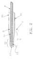
- FIG. 1 illustrates an endovascular laser treatment device with an optical fiber assembled with an infusion catheter according to the present invention.
- FIG. 2 is an enlarged view of the catheter/optical fiber tip area of FIG. 1 with the optical fiber in a protected position within the catheter.
- FIG. 3 is an enlarged view of the catheter/optical fiber tip area of FIG. 1 with the optical fiber tip in an operating position outside of the catheter.
- FIG. 4A depicts the catheter inserted over a guidewire within the enlarged vein.
- FIG. 4D depicts the vein being constricted during the delivery of the drug through the pressure responsive outlets of the catheter with the optical fiber in the protected position.
- FIG. 5 illustrates the endovascular laser treatment device of FIG. 1 with the optical fiber delivering laser energy to the inner wall of the diseased vein while the catheter is being retracted through the vein.
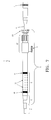
- FIG. 7 is a plan view of the catheter of FIG. 6 assembled with the optical fiber.
- FIG. 1 An endovascular laser treatment device 1 according to the present invention is illustrated in FIG. 1. It is to be noted that the device 1 is illustrated with only a laser optical fiber for purposes of clarity only. Other types of energy delivery source such as RF electrodes can also be used with the present invention.
- the laser treatment device 1 includes an infusion catheter assembly 2 having a Y-connector 3 , and an optical fiber 4 having a SMA connector 5 .
- the catheter 2 is a tubular structure used to facilitate the passage of the optical fiber 4 within the cardiovascular system of a patient. Referring to FIGS. 1 - 3 , the catheter 2 has a catheter tip section 6 with a through-lumen 8 for insertion and passage of the optical fiber 4 .
- the catheter tip section 6 is defined by an occluding zone 22 shown in FIGS. 2 - 3 .
- the optical fiber 4 When the optical fiber 4 is inserted and advanced through the catheter lumen 8 into the occluding zone 22 , the optical fiber 4 in contact with an inner wall of the occluding zone effectively seals the distal end hole of the catheter 2 .
- the occluding zone 22 is dimensioned such that the optical fiber 4 will effectively seal the catheter end hole in both a protected position as shown in FIG. 2 and in an operating position as shown in FIG. 3.
- any fluid injected into the catheter is directed into the vein through the end hole of the catheter.
- the catheter 2 has a Y-connector 3 having a side arm port 7 for the injection of vaso-spasming fluid, saline or other drugs.
- the Y-connector 3 is also defined by through channel with a Touhy-Borst assembly 23 .
- the Touhy-Borst assembly 23 is a gasket assembly used for holding and sealing around guidewires, fibers and other interventional devices inserted into the catheter lumen. By turning the locking mechanism of the Touhy-Borst assembly, the gasket within compresses or opens to allow insertion or sealing of the fiber 4 or other inserted device. When in the locked position, assembly 23 prevents the back-flow of blood or other fluids while holding the fiber 4 in position.
- a passive hemostasis valve may be used to prevent the backflow of blood.
- the ends of the infusion segment 9 of the catheter 2 are marked with radiopaque markers 10 and 11 .
- Marker 10 identifies the distal end of the infusion segment and marker 11 identifies the proximal end of the infusion segment.
- the infusion segment is typically about 50 cm long.
- a plurality of pressure responsive exits such as pressure responsive slits 12 are uniformly formed in a sidewall 30 in the infusion segment 9 of the catheter 2 .
- These pressure responsive slits 12 are in communication with the lumen of the catheter and are designed to open under a predetermined pressure, as described in U.S. Pat. No. 5,250,034, which is incorporated herein by reference.
- each slit there is a plurality of sets of slits with each slit being about 0.015 inches in length.
- Each set of slits includes four slits that are radially spaced from each other at about 90 degrees.
- Each set of slits is longitudinally spaced apart from other sets by about 0.5 cm along the infusion segment 9 .
- the exits 12 can be in the form of a plurality of orifices in the sidewall 30 within the infusion segment 9 of catheter.
- the orifices are in communication with the lumen 8 of the catheter and are designed to provide an exit path for fluid from the lumen 8 into the vein.
- Fluid injected into the side arm port 7 advances through the annular space created between the optical fiber 4 and the sidewall 30 of the catheter 2 .
- the injected fluid exits through the pressure responsive slits 12 uniformly along the infusion segment 9 , so that the fluid such as anesthesia is distributed equally within the vein along the entire treatment area.
- the position of the optical fiber 4 within the catheter tip section 6 may be in either the protected position or operating position as respectively shown in FIGS. 2 and 3. As long as the optical fiber is positioned within the occluding zone 22 of the catheter 2 , fluid flow is directed from the catheter 2 through the pressure responsive outlets 12 and into the vein.
- the length of the infusion segment 9 may be up to 50 cm long to ensure adequate delivery of the therapeutic fluid along the diseased vein segment with a single injection. Although uniform drug delivery is accomplished with the design of the pressure responsive slits, standard sidewall orifices will provide adequate drug delivery throughout the diseased segment of the vein. As long as the end hole of the catheter 2 is occluded by the energy delivery device, sufficient drug volume will be delivered through the sidewall orifices to ensure therapeutic effect throughout the infusion segment 9 .
- the optical fiber 4 depicted in detail in FIG. 2 and FIG. 3, is a standard laser fiber composed of a thin filament of glass or similar material surrounded by a silica cladding 13 .
- the purpose of the silica cladding 13 is to reflect laser energy back into the fiber as it travels the length of the fiber 4 allowing laser energy emission only through the fiber tip 17 .
- a plastic, coaxially mounted protective jacket 14 surrounds the fiber cladding 13 to provide additional strength, protection from surface damage and isolation from moisture.
- the protective jacket 14 terminates approximately 4 mm from the distal tip of the fiber 4 .
- the occluding zone 22 of the catheter tip 6 is dimensioned to ensure that when in the protected position (see FIG. 2), the protective jacket 14 remains within the occluding zone 22 ensuring occlusion of the catheter 2 end hole.
- the optical fiber 4 including the cladding 13 is typically between 400 and 1000 microns in diameter, and preferably about 600 microns.
- the optical fiber 4 including the cladding 13 and the protective jacket 14 is between 870 and 1470 microns, and preferably about 1070 microns.
- the end of the fiber 4 terminates at the energy-emitting end 17 , which is typically a flat-faced surface of the fiber tip 17 . Alternatively, the fiber tip face 17 may be radiused or have a non-flat surface.
- the fiber 4 is attached to a connector 5 such as a standard SMA connector.
- the SMA connector 5 connects the fiber 4 to a laser energy source (not shown).
- mapping of the vein is a very time-consuming step for the physician.
- the present invention advantageously eliminates the conventional mapping step from the treatment procedure.
- the greater saphenous vein 15 is accessed using a standard Seldinger technique.
- a guide wire 16 is advanced into the vein 15 , and then the catheter 2 is fed over the guidewire 16 (FIG. 4A) and advanced to 1 to 2 centimeters below the sapheno-femoral junction. Position of the catheter 2 is then verified and adjusted if necessary using ultrasound. Once correct positioning is confirmed, the guidewire 16 is removed leaving the catheter 2 in place within the vein 15 as depicted in FIG. 4B.
- the distal tip of the optical fiber 4 is then inserted into the catheter Y-connector 3 (not shown) and advanced until the fiber jacket 14 of optical fiber 4 is positioned within the occluding zone 22 of the catheter 2 in the protective position (FIG. 2).
- the Touhy-Borst assembly 23 is turned to lock the optical fiber in place in the protected position. In that state, the catheter 2 end hole is effectively occluded by the fiber jacket 14 .
- the therapeutic fluid is administered from within the catheter without the need to make any punctures.
- the drug is infused into the catheter 1 in a single bolus.
- the fluid advances into the annular fluid passageway formed between the optical fiber 4 and catheter 2 sidewall 30 . Occlusion of the catheter end hole by the optic fiber jacket 14 causes the drug 21 to exit from the slits 12 in the sidewall 30 of the catheter into the vein 15 , as shown in FIG. 4D.
- the drug 21 does not exit from the end hole of the catheter 2 because it is effectively occluded by the optical fiber jacket 14 .
- Drug can be delivered with the laser in the protected position as shown in FIG. 2 or in the operating position as shown in FIG. 3, based on the treating physician's preference.
- the fluid 21 being infused into the vein has vaso-spasming and anesthetic characteristics.
- the induced spasm in turn causes the vein to constrict.
- fluid such as Lidocaine, hypertonic saline and sclerosing agents may be injected to induce vaso-spasms.
- Sclerosing agents serve an additional function of causing vascular fibrosis by acting upon the vessel wall.
- a solution of 1% Sotradecol or Polidocanol is administered to the vein.
- Anesthetics are used for an additional purpose of decreasing pain during the procedure.
- Lidocaine is typically used to alleviate patient pain.
- a mixture of 10-30 cc of 5% lidocaine with epinephrine is used.
- Marcaine a longeracting form of lidocaine, can be injected through the side arm port 7 .
- the vaso-spasming characteristics of lidocaine and epinephrine act upon the inner wall of the diseased vein causing it to spasm and constrict around the endovascular treatment device 1 .
- the enlarged vein diameter is significantly reduced in reaction to the delivery of the drug to the inner vein wall.
- Complete spasm of the vein is desirable to reduce the size of the vein diameter prior to laser energy delivery.
- the distance between the vein and the nerve increases. The extra distance provides a barrier to prevent non-targeted thermal damage to the nerve during laser energy delivery.
- the design and uniform spacing of the pressure responsive slits 12 ensure uniform and rapid delivery of the vaso-spasming and/or anesthetic fluid along the entire infusion segment 9 of the catheter 2 . Accordingly, the vein 15 can be treated with a single fluid injection. This aspect of the invention provides substantial time and cost savings to the treating physician while reducing the trauma, pain and post-operative bruising of the patient.
- an endovenous laser procedure may take 45 to 120 minutes including prep and post-procedure steps. Of that time, approximately 10 to 20 minutes are allocated to completely anesthetize the entire vein segment being treated. With the treatment method described in this invention, however, the administration of anesthetic and/or vasospasming fluid is reduced to literally several seconds.
- the total amount of lidocaine or like drug injected using the catheter assembly of the present invention is significantly less than the amount required for perivenous injections. Because the drug is being delivered directly to the inner vein wall, less drug is required. Typically, only 10-30 cc of anesthesia is required when delivered intravenously compared with 100-200 cc tumescent fluid when delivered perivenously.
- FIG. 6 An alternative embodiment of the catheter 2 is depicted in FIG. 6.
- the catheter 2 is comprised of an inner through lumen 25 and an outer, coaxial lumen 26 for fluid flow.
- the catheter 2 is defined by a T-connector 28 having a side arm port 7 for the injection of vaso-spasming agents, saline or other drugs.
- the T-connector 28 is also defined by through channel with a Touhy-Borst assembly 23 as depicted in FIG. 7. Fluid is infused through the side port 7 into the annual space of the coaxial lumen 26 .
- the coaxial lumen 26 is an annular lumen and surrounds the inner through lumen 25 .
- fluid 21 advances through the annular fluid passageway 26 exiting through the pressure responsive exits 12 into the vessel lumen.
- fluid can be administered intravenously without occlusion of the catheter 2 end hole because of the coaxial design. Accordingly, vaso-constricting and anesthetic drugs can be injected into the catheter 2 prior to inserting the fiber optic 4 into the inner through lumen 25 of the catheter 2 .
- FIG. 5 depicts the catheter 2 and laser fiber 4 as the combined assembly is being pulled back down the course of the vein 15 .
- laser energy 18 is delivered to the inner wall of the vein as the catheter 2 is withdrawn.
- the laser energy 18 produces localized thermal injury to the endothelium and vein wall causing further reduction in the diameter of the vein and ultimately occlusion of the vein. Specifically, the thermal energy contacts the blood causing hot bubbles of gas to be created. The gas bubbles transfer the thermal energy to the vein wall, causing cell necrosis and eventual vein collapse.
- section 19 of the diseased vein segment 15 has been treated with laser energy and is permanently occluded.
- Section 20 of the diseased vein segment 15 has not been exposed to laser energy and thus remains open but constricted. After the entire vein segment 15 has been treated, the thermally damaged vessel becomes occluded and can no longer support blood flow.
- the procedure for treating the varicose vein is considered to be complete when the desired length of the greater saphenous vein or other vein has been exposed to laser energy. Normally, the laser generator is turned off when the fiber tip 17 is approximately 3 centimeters from the access site. The fiber 4 /catheter 2 assembly is then removed from the body as a single unit.
Abstract
Description
- This application claims priority to U.S. Provisional Application No. 60/370,050, filed Apr.4, 2002, which is incorporated herein by reference.
- The present invention relates to a medical device for treatment of vascular diseases, and more particularly, to a device for treating varicose veins using an endovascular laser optical fiber and catheter.
- Veins are thin-walled and contain one-way valves that control blood flow. Normally, the valves open to allow blood to flow into the deeper veins and close to prevent back-flow into the superficial veins. When the valves are malfunctioning or only partially functioning, however, they no longer prevent the back-flow of blood into the superficial veins. As a result, venous pressure builds at the site of the faulty valves. Because the veins are thin walled and not able to withstand the increased pressure, they become what are known as varicose veins which are veins that are dilated, tortuous or engorged.
- In particular, varicose veins of the lower extremities is one of the most common medical conditions of the adult population. It is estimated that varicose veins affect approximately 25% of adult females and 10% of males. Symptoms include discomfort, aching of the legs, itching, cosmetic deformities, and swelling. If left untreated, varicose veins may cause medical complications such as bleeding, phlebitis, ulcerations, thrombi and lipodermatosclerosis.
- Traditional treatments for varicosities include both temporary and permanent techniques. Temporary treatments involve use of compression stockings and elevation of the diseased extremities. While providing temporary relief of symptoms, these techniques do not correct the underlying cause, that is the faulty valves. Permanent treatments include surgical excision of the diseased segments, ambulatory phlebectomy, and occlusion of the vein through chemical or thermal means.
- Surgical excision requires general anesthesia and a long recovery period. Even with its high clinical success rate, surgical excision is rapidly becoming an outmoded technique due to the high costs of treatment and complication risks from surgery. Ambulatory phlebectomy involves avulsion of the varicose vein segment using multiple stab incisions through the skin. The procedure is done on an outpatient basis, but is still relatively expensive due to the length of time required to perform the procedure.
- Chemical occlusion, also known as sclerotherapy, is an in-office procedure involving the injection of an irritant chemical into the vein. The chemical acts upon the inner lining of the vein walls causing them to occlude and block blood flow. Although a popular treatment option, complications can be severe including skin ulceration, anaphylactic reactions and permanent skin staining. Another disadvantage is that treatment is limited to veins of a particular size range. In addition, there is a relatively high recurrence rate due to vessel recanalization.
- Endovascular thermal energy therapy is a relatively new treatment technique for venous reflux diseases. With this technique, thermal energy in the form of laser or radio frequency (RF) energy is delivered by an energy delivery device that is percutaneously inserted into the diseased vein prior to energy delivery. In a laser therapy, an optical fiber is used as the energy delivery device whereas in an RF therapy, RF electrodes are used as the energy delivery device. The procedure for the thermal energy therapy involves inserting an introducer catheter or sheath and advancing it to within a few centimeters of the sapheno-femoral junction of the greater saphenous vein. In the case of laser therapy, once the introducer catheter is properly positioned, a flexible optical fiber is inserted into the lumen of the catheter or sheath and advanced until the distal fiber tip is near the catheter tip but still protected within the catheter lumen.
- Once the catheter and flexible optical fiber are positioned within the vein, the tissue immediately surrounding the diseased vessel segment is subjected to numerous needle punctures to make percutaneous injections of a tumescent anesthetic agent. The injections, typically lidocaine with or without epinephrine, are administered under ultrasonic guidance along the entire length of the greater saphenous vein into the perivenous space. The tumescent injections perform several functions. First, the anesthetic injection inhibits pain caused from the application of energy to the vein. Second, the injection causes the vein to spasm which reduces the diameter of the vein and brings the vessel wall in close proximity to the catheter and the optical fiber. The constricted vessel diameter facilitates efficient energy transmission to the vessel wall through the optical fiber when the laser energy is applied. Third, the tumescent injection also provides a barrier between the vessel and the adjacent tissue and nerve structures, which restricts the heat damage to only the vessel itself and prevents non-target tissue damage.
- After the anesthetic injections are made through multiple puncture sites, the catheter is withdrawn approximately 1-3 centimeters while the optical fiber is held steady to expose the distal tip of the optical fiber. A laser generator is then activated to cause laser energy to be emitted from the bare flat tip of the fiber into the constricted vessel. The thermal energy from the laser contacts the blood causing hot bubbles of gas to be created. The gas bubbles transfer thermal energy to the vein wall, causing cell necrosis and eventual vein collapse. With the laser generator turned on, the fiber and catheter are slowly withdrawn as a single unit until the entire diseased segment of the vessel has been treated. The damaged vessel becomes occluded, collapses and can no longer support blood flow.
- For such endovascular laser treatment, the injection of tumescent anesthesia through multiple punctures along the diseased segment is considered a standard and necessary step in the treatment protocol. However, there are several disadvantages associated with such a conventional method of administering local anesthesia injections. The anesthetic injection process is cumbersome and is the most time-consuming step in the treatment procedure because of the number of punctures that has to be made. Typically, injections are administered along the entire length of the greater saphenous vein in 2 - 3 cm increments. The total injection length varies but is usually between 30 and 40 cm.
- Accordingly, approximately 10 to 20 injections, and therefore 10 to 20 punctures, are required before the laser treatment can begin.
- In addition to the time required to administer multiple injections, peri-venous injections are disadvantageous because they are painful to the patient, leave puncture wounds, and may increase bruising and post-procedure complications because of the way the injection is administered. Each injection is administered under ultrasound guidance due to the necessity of accurately positioning the needle between the fascia and vein. The physician will often use the catheter as a target when inserting the needle into the patient's tissue. In some cases, a physician may inadvertently puncture the vein and even the catheter wall when positioning the needle. When this occurs, the vein wall may be lacerated resulting in excessive bruising and patient discomfort. Lacerations of the vein wall may also result in non-targeted thermal damage outside of the vessel as the gas bubble created by the laser may escape through the laceration into the adjoining tissue and nerve structures. Another disadvantage is that needle punctures that penetrate the catheter wall may damage the integrity of the catheter and/or the optical fiber. Finally, multiple injections require the use of multiple needles and other accessories such as gauze pads and syringes. The medical staff performing the procedure is thus at an increased risk of accidental needle sticks and the potential health hazards associated with unintentional exposure to contaminated blood and other body fluids.
- Therefore, it is desirable to provide an improved device and method which delivers vaso-spasming and anesthetic fluids and other procedural drugs quickly, completely and uniformly without multiple injections or multiple needle sticks. It is also desirable that the device and method prevent thermal damage to non-targeted adjacent tissues and nerve structures without requiring peri-venous injections along the entire length of the vein. Further, it is desirable provide such a method and device that reduce patient discomfort associated with needle sticks, decrease procedure time, and minimize postprocedure complications caused by multiple punctures.
- According to the principles of the present invention, a catheter device for treating a vascular disease is provided. The catheter device includes an energy delivery device such as an optical fiber for delivering laser energy and a catheter designed to be inserted into a blood vessel. The catheter lumen receives the energy delivery device and a fluid such as an anesthetic agent or vasoconstricting agent. According to the invention, a plurality of exits are disposed in the sidewall of the catheter. The exits are in communication with the catheter lumen and are used to administer the fluid into the blood vessel.
- The catheter may have a single lumen through which both the energy delivery device and the fluid can be received. Alternatively, the catheter may have two separate lumens in which one lumen receives the energy delivery device and the other lumen receives the fluid.
- In one aspect of the present invention, the exits of the catheter device are pressure responsive exits that are normally closed and are designed to open under a certain amount of pressure within the lumen.
- By administering the fluids from within the catheter lumen, the present invention eliminates the need to make numerous external punctures to deliver tumescent injections. As a result, the invention provides substantial time and cost savings to a treating physician while reducing the trauma, pain and post-operative bruising of the patient.
- FIG. 1 illustrates an endovascular laser treatment device with an optical fiber assembled with an infusion catheter according to the present invention.
- FIG. 2 is an enlarged view of the catheter/optical fiber tip area of FIG. 1 with the optical fiber in a protected position within the catheter.
- FIG. 3 is an enlarged view of the catheter/optical fiber tip area of FIG. 1 with the optical fiber tip in an operating position outside of the catheter.
- FIGS. 4A-4E illustrate the method of drug delivery using the device of FIG. 1.
- FIG. 4A depicts the catheter inserted over a guidewire within the enlarged vein.
- FIG. 4B illustrates the catheter within the enlarged vein after guidewire removal.
- FIG. 4C shows the optical fiber in the protected position within the catheter positioned within the enlarged vein.
- FIG. 4D depicts the vein being constricted during the delivery of the drug through the pressure responsive outlets of the catheter with the optical fiber in the protected position.
- FIG. 4E depicts the catheter with the optical fiber in the operating position within the constricted vein.
- FIG. 5 illustrates the endovascular laser treatment device of FIG. 1 with the optical fiber delivering laser energy to the inner wall of the diseased vein while the catheter is being retracted through the vein.
- FIG. 6 is a sectional view of an alternative embodiment of a catheter with a co-axial lumen.
- FIG. 7 is a plan view of the catheter of FIG. 6 assembled with the optical fiber.
- An endovascular laser treatment device 1 according to the present invention is illustrated in FIG. 1. It is to be noted that the device 1 is illustrated with only a laser optical fiber for purposes of clarity only. Other types of energy delivery source such as RF electrodes can also be used with the present invention.
- The laser treatment device 1 includes an
infusion catheter assembly 2 having a Y-connector 3, and anoptical fiber 4 having aSMA connector 5. Thecatheter 2 is a tubular structure used to facilitate the passage of theoptical fiber 4 within the cardiovascular system of a patient. Referring to FIGS. 1-3, thecatheter 2 has acatheter tip section 6 with a through-lumen 8 for insertion and passage of theoptical fiber 4. Thecatheter tip section 6 is defined by an occludingzone 22 shown in FIGS. 2-3. When theoptical fiber 4 is inserted and advanced through thecatheter lumen 8 into the occludingzone 22, theoptical fiber 4 in contact with an inner wall of the occluding zone effectively seals the distal end hole of thecatheter 2. The occludingzone 22 is dimensioned such that theoptical fiber 4 will effectively seal the catheter end hole in both a protected position as shown in FIG. 2 and in an operating position as shown in FIG. 3. When the optical fiber is not advanced into the occludingzone 22, any fluid injected into the catheter is directed into the vein through the end hole of the catheter. - In the embodiment shown, the
catheter 2 has a Y-connector 3 having aside arm port 7 for the injection of vaso-spasming fluid, saline or other drugs. The Y-connector 3 is also defined by through channel with a Touhy-Borst assembly 23. The Touhy-Borst assembly 23 is a gasket assembly used for holding and sealing around guidewires, fibers and other interventional devices inserted into the catheter lumen. By turning the locking mechanism of the Touhy-Borst assembly, the gasket within compresses or opens to allow insertion or sealing of thefiber 4 or other inserted device. When in the locked position,assembly 23 prevents the back-flow of blood or other fluids while holding thefiber 4 in position. In an alternative embodiment, a passive hemostasis valve may be used to prevent the backflow of blood. - The ends of the
infusion segment 9 of thecatheter 2 are marked withradiopaque markers Marker 10 identifies the distal end of the infusion segment andmarker 11 identifies the proximal end of the infusion segment. The infusion segment is typically about 50 cm long. According to the present invention, a plurality of pressure responsive exits such as pressureresponsive slits 12 are uniformly formed in asidewall 30 in theinfusion segment 9 of thecatheter 2. These pressureresponsive slits 12 are in communication with the lumen of the catheter and are designed to open under a predetermined pressure, as described in U.S. Pat. No. 5,250,034, which is incorporated herein by reference. In one embodiment, there is a plurality of sets of slits with each slit being about 0.015 inches in length. Each set of slits includes four slits that are radially spaced from each other at about 90 degrees. Each set of slits is longitudinally spaced apart from other sets by about 0.5 cm along theinfusion segment 9. - Alternatively, the
exits 12 can be in the form of a plurality of orifices in thesidewall 30 within theinfusion segment 9 of catheter. The orifices are in communication with thelumen 8 of the catheter and are designed to provide an exit path for fluid from thelumen 8 into the vein. - Fluid injected into the
side arm port 7 advances through the annular space created between theoptical fiber 4 and thesidewall 30 of thecatheter 2. When the catheter end hole is occluded by theoptical fiber 4, the injected fluid exits through the pressureresponsive slits 12 uniformly along theinfusion segment 9, so that the fluid such as anesthesia is distributed equally within the vein along the entire treatment area. The position of theoptical fiber 4 within thecatheter tip section 6 may be in either the protected position or operating position as respectively shown in FIGS. 2 and 3. As long as the optical fiber is positioned within the occludingzone 22 of thecatheter 2, fluid flow is directed from thecatheter 2 through the pressureresponsive outlets 12 and into the vein. - The length of the
infusion segment 9 may be up to 50 cm long to ensure adequate delivery of the therapeutic fluid along the diseased vein segment with a single injection. Although uniform drug delivery is accomplished with the design of the pressure responsive slits, standard sidewall orifices will provide adequate drug delivery throughout the diseased segment of the vein. As long as the end hole of thecatheter 2 is occluded by the energy delivery device, sufficient drug volume will be delivered through the sidewall orifices to ensure therapeutic effect throughout theinfusion segment 9. - The
optical fiber 4, depicted in detail in FIG. 2 and FIG. 3, is a standard laser fiber composed of a thin filament of glass or similar material surrounded by asilica cladding 13. The purpose of thesilica cladding 13 is to reflect laser energy back into the fiber as it travels the length of thefiber 4 allowing laser energy emission only through thefiber tip 17. A plastic, coaxially mountedprotective jacket 14 surrounds thefiber cladding 13 to provide additional strength, protection from surface damage and isolation from moisture. Theprotective jacket 14 terminates approximately 4 mm from the distal tip of thefiber 4. As shown in FIGS. 2 and 3, the occludingzone 22 of thecatheter tip 6 is dimensioned to ensure that when in the protected position (see FIG. 2), theprotective jacket 14 remains within the occludingzone 22 ensuring occlusion of thecatheter 2 end hole. - The
optical fiber 4 including thecladding 13 is typically between 400 and 1000 microns in diameter, and preferably about 600 microns. Theoptical fiber 4 including thecladding 13 and theprotective jacket 14 is between 870 and 1470 microns, and preferably about 1070 microns. The end of thefiber 4 terminates at the energy-emittingend 17, which is typically a flat-faced surface of thefiber tip 17. Alternatively, thefiber tip face 17 may be radiused or have a non-flat surface. At the proximal end, thefiber 4 is attached to aconnector 5 such as a standard SMA connector. TheSMA connector 5 connects thefiber 4 to a laser energy source (not shown). - A method of using the endovascular laser device 1 in treating varicose veins will now be described with reference to FIGS. 4A-4E. The treatment procedure begins with the standard pre-operative preparation of the patient as is well known in the thermal energy treatment art. The patient is examined with ultrasound to identify and locate the source of venous reflux, typically the greater saphenous vein. Treatment is not necessarily limited to the greater saphenous vein; diseased segments of the lesser saphenous vein and other veins may be treated using endovenous laser or RF procedures. The saphenofemoral junction and any anatomical variations of the venous system are also identified during pre-treatment ultrasound After the ultrasound examination, the patient's leg is draped and cleansed in preparation for the procedure.
- With prior art methods, the patient's diseased venous segments are marked on the skin surface. Typically, ultrasound guidance is used to map the greater saphenous vein from the sapheno-femoral junction to the popliteal area. The physician marks the route of the vein with a marker under ultrasound guidance. The purpose of this mapping is to provide a visual identifying line for the physician to follow when injecting peri-venous tumescent anesthesia along the length of the diseased vein. As persons of ordinary skill in the art can appreciate, mapping of the vein is a very time-consuming step for the physician. As will be explained in more detail later herein, the present invention advantageously eliminates the conventional mapping step from the treatment procedure.
- There is no need to pre-map the patient's venous pathway since the anesthetic or vasospasming drug will be administered intra-venously without punctures in a single injection through the catheter.
- After the patient has been prepped, the greater
saphenous vein 15 is accessed using a standard Seldinger technique. Aguide wire 16 is advanced into thevein 15, and then thecatheter 2 is fed over the guidewire 16 (FIG. 4A) and advanced to 1 to 2 centimeters below the sapheno-femoral junction. Position of thecatheter 2 is then verified and adjusted if necessary using ultrasound. Once correct positioning is confirmed, theguidewire 16 is removed leaving thecatheter 2 in place within thevein 15 as depicted in FIG. 4B. - As shown in FIG. 4C, the distal tip of the
optical fiber 4 is then inserted into the catheter Y-connector 3 (not shown) and advanced until thefiber jacket 14 ofoptical fiber 4 is positioned within the occludingzone 22 of thecatheter 2 in the protective position (FIG. 2). After positioning, the Touhy-Borst assembly 23 is turned to lock the optical fiber in place in the protected position. In that state, thecatheter 2 end hole is effectively occluded by thefiber jacket 14. - Once the
catheter 2 andoptical fiber 4 are positioned, infusion of one or more drugs is performed. As discussed earlier in the background section, the conventional drug infusion process involves making 10 to 20 needle punctures to deliver 10 to 20 perivenous injections under ultrasound guidance. For each injection, the needle must be positioned accurately using ultrasound guidance. Typically, between 3-10 cc of tumescent fluid are injected at each puncture site. Up to 200 cc of drug may be required to effectively prepare the vein and patient for the procedure. The injections can be painful to the patient, leave multiple puncture wounds and may increase bruising and post-procedure complications. The injections also may compromise the integrity of the delivery system due to penetration of a catheter wall by inaccurate needle sticks. - According to the principles of the present invention, however, the therapeutic fluid is administered from within the catheter without the need to make any punctures. Specifically, using a standard syringe connected to the
side arm port 7 of the catheter Y-connector 3 (FIG. 1), the drug is infused into the catheter 1 in a single bolus. Under low, steady pressure, the fluid advances into the annular fluid passageway formed between theoptical fiber 4 andcatheter 2sidewall 30. Occlusion of the catheter end hole by theoptic fiber jacket 14 causes thedrug 21 to exit from theslits 12 in thesidewall 30 of the catheter into thevein 15, as shown in FIG. 4D. Thedrug 21 does not exit from the end hole of thecatheter 2 because it is effectively occluded by theoptical fiber jacket 14. Drug can be delivered with the laser in the protected position as shown in FIG. 2 or in the operating position as shown in FIG. 3, based on the treating physician's preference. - The fluid 21 being infused into the vein has vaso-spasming and anesthetic characteristics. The induced spasm in turn causes the vein to constrict. For example, fluid such as Lidocaine, hypertonic saline and sclerosing agents may be injected to induce vaso-spasms. Sclerosing agents serve an additional function of causing vascular fibrosis by acting upon the vessel wall. Typically a solution of 1% Sotradecol or Polidocanol is administered to the vein.
- Anesthetics are used for an additional purpose of decreasing pain during the procedure. Lidocaine is typically used to alleviate patient pain. Typically a mixture of 10-30 cc of 5% lidocaine with epinephrine is used. Alternatively, Marcaine, a longeracting form of lidocaine, can be injected through the
side arm port 7. - The vaso-spasming characteristics of lidocaine and epinephrine act upon the inner wall of the diseased vein causing it to spasm and constrict around the endovascular treatment device 1. Referring to FIG. 4E, the enlarged vein diameter is significantly reduced in reaction to the delivery of the drug to the inner vein wall. Complete spasm of the vein is desirable to reduce the size of the vein diameter prior to laser energy delivery. As the vein spasms and constricts, the distance between the vein and the nerve increases. The extra distance provides a barrier to prevent non-targeted thermal damage to the nerve during laser energy delivery.
- The design and uniform spacing of the pressure
responsive slits 12 ensure uniform and rapid delivery of the vaso-spasming and/or anesthetic fluid along theentire infusion segment 9 of thecatheter 2. Accordingly, thevein 15 can be treated with a single fluid injection. This aspect of the invention provides substantial time and cost savings to the treating physician while reducing the trauma, pain and post-operative bruising of the patient. - Typically, an endovenous laser procedure may take 45 to 120 minutes including prep and post-procedure steps. Of that time, approximately 10 to 20 minutes are allocated to completely anesthetize the entire vein segment being treated. With the treatment method described in this invention, however, the administration of anesthetic and/or vasospasming fluid is reduced to literally several seconds.
- With the present invention, patient side effects and complications from multiple needle punctures are avoided. Patient pain associated with the needle puncture and injection of fluid into tissue is completely eliminated with the endovascular laser technique described herein. Post-procedure bandaging of the patient's leg is simplified because of the absence of puncture wounds.
- In addition, the total amount of lidocaine or like drug injected using the catheter assembly of the present invention is significantly less than the amount required for perivenous injections. Because the drug is being delivered directly to the inner vein wall, less drug is required. Typically, only 10-30 cc of anesthesia is required when delivered intravenously compared with 100-200 cc tumescent fluid when delivered perivenously.
- An alternative embodiment of the
catheter 2 is depicted in FIG. 6. Thecatheter 2 is comprised of an inner throughlumen 25 and an outer,coaxial lumen 26 for fluid flow. At the proximal end, thecatheter 2 is defined by a T-connector 28 having aside arm port 7 for the injection of vaso-spasming agents, saline or other drugs. The T-connector 28 is also defined by through channel with a Touhy-Borst assembly 23 as depicted in FIG. 7. Fluid is infused through theside port 7 into the annual space of thecoaxial lumen 26. Thecoaxial lumen 26 is an annular lumen and surrounds the inner throughlumen 25. When injected through theside port 7, the fluid 21 advances through theannular fluid passageway 26 exiting through the pressureresponsive exits 12 into the vessel lumen. In this embodiment, fluid can be administered intravenously without occlusion of thecatheter 2 end hole because of the coaxial design. Accordingly, vaso-constricting and anesthetic drugs can be injected into thecatheter 2 prior to inserting thefiber optic 4 into the inner throughlumen 25 of thecatheter 2. - Alternatively, drugs can be administered through the catheter pressure
responsive exits 12 with thefiber optic 4 positioned within thecatheter lumen 26 in the protected or operating position. As shown in FIG. 7, theoptical fiber 4 is inserted and advanced into the throughlumen 25 ofcatheter 2. By turning the locking mechanism of the TouhyBorst assembly, the gasket within compresses or opens allowing insertion or sealing of thefiber 4 or other inserted device. When in the locked position,assembly 23 prevents the back-flow of blood or other fluids while holding thefiber 4 in position. In an alternative embodiment, a passive hemostasis valve may be used to prevent the backflow of blood. - After the anesthetic and/or vaso-spasming fluid has been delivered to the vein, the patient is ready for the delivery of laser energy to the diseased vein. The delivery system is repositioned from the protected position as shown in FIGS. 2 and 4D to the operating position as shown in FIGS. 3 and 4E to expose the laser
optical fiber tip 17 ofoptical fiber 4. Typically, thecatheter 2 is retracted approximately 2-4 cm while thelaser fiber 4 is held steady to expose thefiber 4energy emitting end 17 as shown in FIG. 4E. The endovascular laser treatment device 1 is now ready for the delivery of laser energy to the diseased vein segment. - The laser generator (not shown) is activated and the
catheter 2/fiber 4 assembly is slowly withdrawn as a single unit through the vein, preferably at a rate of 1- 3 millimeters per second. FIG. 5 depicts thecatheter 2 andlaser fiber 4 as the combined assembly is being pulled back down the course of thevein 15. As shown in FIG. 3,laser energy 18 is delivered to the inner wall of the vein as thecatheter 2 is withdrawn. Thelaser energy 18 produces localized thermal injury to the endothelium and vein wall causing further reduction in the diameter of the vein and ultimately occlusion of the vein. Specifically, the thermal energy contacts the blood causing hot bubbles of gas to be created. The gas bubbles transfer the thermal energy to the vein wall, causing cell necrosis and eventual vein collapse. - In FIG. 5,
section 19 of thediseased vein segment 15 has been treated with laser energy and is permanently occluded.Section 20 of thediseased vein segment 15 has not been exposed to laser energy and thus remains open but constricted. After theentire vein segment 15 has been treated, the thermally damaged vessel becomes occluded and can no longer support blood flow. - The procedure for treating the varicose vein is considered to be complete when the desired length of the greater saphenous vein or other vein has been exposed to laser energy. Normally, the laser generator is turned off when the
fiber tip 17 is approximately 3 centimeters from the access site. Thefiber 4/catheter 2 assembly is then removed from the body as a single unit. - While certain novel features of this invention have been shown and described above, the present invention may be embodied in other specific forms without departing from the spirit or essential characteristics of the invention. The described embodiments are to be considered in all respects only as illustrative and not as restrictive. Various omissions, modifications, substitutions and changes in the forms and details of the device illustrated and in its operation can be made by those skilled in the art without departing in any way from the spirit of the present invention.
Claims (26)
Priority Applications (4)
| Application Number | Priority Date | Filing Date | Title |
|---|---|---|---|
| US10/393,922 US7163533B2 (en) | 2002-04-04 | 2003-03-20 | Vascular treatment device and method |
| US11/303,818 US9440046B2 (en) | 2002-04-04 | 2005-12-15 | Venous insufficiency treatment method |
| US14/989,167 US9782562B2 (en) | 2002-04-04 | 2016-01-06 | Venous insufficiency treatment method |
| US15/270,562 US20170106167A1 (en) | 2002-04-04 | 2016-09-20 | Venous insufficiency treatment method |
Applications Claiming Priority (2)
| Application Number | Priority Date | Filing Date | Title |
|---|---|---|---|
| US37005002P | 2002-04-04 | 2002-04-04 | |
| US10/393,922 US7163533B2 (en) | 2002-04-04 | 2003-03-20 | Vascular treatment device and method |
Related Child Applications (1)
| Application Number | Title | Priority Date | Filing Date |
|---|---|---|---|
| US11/303,818 Continuation-In-Part US9440046B2 (en) | 2002-04-04 | 2005-12-15 | Venous insufficiency treatment method |
Publications (2)
| Publication Number | Publication Date |
|---|---|
| US20030191460A1 true US20030191460A1 (en) | 2003-10-09 |
| US7163533B2 US7163533B2 (en) | 2007-01-16 |
Family
ID=28042070
Family Applications (1)
| Application Number | Title | Priority Date | Filing Date |
|---|---|---|---|
| US10/393,922 Expired - Fee Related US7163533B2 (en) | 2002-04-04 | 2003-03-20 | Vascular treatment device and method |
Country Status (5)
| Country | Link |
|---|---|
| US (1) | US7163533B2 (en) |
| EP (1) | EP1350481B1 (en) |
| AT (1) | ATE353599T1 (en) |
| DE (1) | DE60311692T2 (en) |
| ES (1) | ES2280692T3 (en) |
Cited By (61)
| Publication number | Priority date | Publication date | Assignee | Title |
|---|---|---|---|---|
| US20020068866A1 (en) * | 2000-08-14 | 2002-06-06 | Zikorus Arthur W. | Method and apparatus for positioning a catheter relative to an anatomical junction |
| US20040199156A1 (en) * | 2003-04-02 | 2004-10-07 | Rioux Robert F. | Endovenous ablation mechanism with feedback control |
| US20050015123A1 (en) * | 2003-06-30 | 2005-01-20 | Paithankar Dilip Y. | Endovascular treatment of a blood vessel using a light source |
| WO2005070317A1 (en) * | 2004-01-27 | 2005-08-04 | Arcusa Villacampa Francisco Ja | Handpiece for surgical diode laser application by means of fibre optic |
| US20050288655A1 (en) * | 2004-06-29 | 2005-12-29 | Howard Root | Laser fiber for endovenous therapy having a shielded distal tip |
| US20070055326A1 (en) * | 2005-07-21 | 2007-03-08 | Farley Brian E | Method of treating a hollow anatomical structure with a thermal catheter |
| US20070179486A1 (en) * | 2004-06-29 | 2007-08-02 | Jeff Welch | Laser fiber for endovenous therapy having a shielded distal tip |
| US20070244371A1 (en) * | 2006-04-04 | 2007-10-18 | Nguyen Hoa D | Phlebectomy illumination device and methods |
| US20080039728A1 (en) * | 2006-03-09 | 2008-02-14 | Dharmendra Pal | Catheters and Related Systems and Methods |
| US20080249399A1 (en) * | 2003-10-31 | 2008-10-09 | Appling William M | Endovascular treatment apparatus and method |
| US20080255475A1 (en) * | 2007-04-16 | 2008-10-16 | C. R. Bard, Inc. | Guidewire-assisted catheter placement system |
| US20080275380A1 (en) * | 2006-11-02 | 2008-11-06 | Cooltouch Incorporated | Sonic endovenous catheter |
| US20080281308A1 (en) * | 2007-05-07 | 2008-11-13 | Ceramoptec Industries, Inc. | Device and method for improved vascular laser treatment |
| US20090082760A1 (en) * | 2007-09-25 | 2009-03-26 | Kenneth Zinn | Guidewire tipped laser fiber |
| US20100280328A1 (en) * | 2009-05-01 | 2010-11-04 | Tyco Healthcare Group, Lp | Methods and systems for illumination during phlebectomy procedures |
| US7955369B2 (en) | 2004-09-27 | 2011-06-07 | Tyco Healthcare Group Lp | Systems and methods for treating a hollow anatomical structure |
| US8388546B2 (en) | 2006-10-23 | 2013-03-05 | Bard Access Systems, Inc. | Method of locating the tip of a central venous catheter |
| US8388541B2 (en) | 2007-11-26 | 2013-03-05 | C. R. Bard, Inc. | Integrated system for intravascular placement of a catheter |
| US8437833B2 (en) | 2008-10-07 | 2013-05-07 | Bard Access Systems, Inc. | Percutaneous magnetic gastrostomy |
| US20130138033A1 (en) * | 2011-11-25 | 2013-05-30 | Techlamed S.R.L. Societa Unipersonale | Laser assisted sclerotherapy method for treating varicose veins |
| US8465451B2 (en) | 2005-06-22 | 2013-06-18 | Covidien Lp | Methods and apparatus for introducing tumescent fluid to body tissue |
| US8478382B2 (en) | 2008-02-11 | 2013-07-02 | C. R. Bard, Inc. | Systems and methods for positioning a catheter |
| US8512256B2 (en) | 2006-10-23 | 2013-08-20 | Bard Access Systems, Inc. | Method of locating the tip of a central venous catheter |
| US20140005594A1 (en) * | 2011-02-07 | 2014-01-02 | Cermavein | Device and Method for Injecting Pulsed Steam Into a Human or Animal Vessel E.G. a Vein |
| USD699359S1 (en) | 2011-08-09 | 2014-02-11 | C. R. Bard, Inc. | Ultrasound probe head |
| US8781555B2 (en) | 2007-11-26 | 2014-07-15 | C. R. Bard, Inc. | System for placement of a catheter including a signal-generating stylet |
| US8784336B2 (en) | 2005-08-24 | 2014-07-22 | C. R. Bard, Inc. | Stylet apparatuses and methods of manufacture |
| US8801693B2 (en) | 2010-10-29 | 2014-08-12 | C. R. Bard, Inc. | Bioimpedance-assisted placement of a medical device |
| US8849382B2 (en) | 2007-11-26 | 2014-09-30 | C. R. Bard, Inc. | Apparatus and display methods relating to intravascular placement of a catheter |
| USD724745S1 (en) | 2011-08-09 | 2015-03-17 | C. R. Bard, Inc. | Cap for an ultrasound probe |
| US9125578B2 (en) | 2009-06-12 | 2015-09-08 | Bard Access Systems, Inc. | Apparatus and method for catheter navigation and tip location |
| US9211107B2 (en) | 2011-11-07 | 2015-12-15 | C. R. Bard, Inc. | Ruggedized ultrasound hydrogel insert |
| US9339206B2 (en) | 2009-06-12 | 2016-05-17 | Bard Access Systems, Inc. | Adaptor for endovascular electrocardiography |
| US9445734B2 (en) | 2009-06-12 | 2016-09-20 | Bard Access Systems, Inc. | Devices and methods for endovascular electrography |
| US9456766B2 (en) | 2007-11-26 | 2016-10-04 | C. R. Bard, Inc. | Apparatus for use with needle insertion guidance system |
| US9492097B2 (en) | 2007-11-26 | 2016-11-15 | C. R. Bard, Inc. | Needle length determination and calibration for insertion guidance system |
| US9521961B2 (en) | 2007-11-26 | 2016-12-20 | C. R. Bard, Inc. | Systems and methods for guiding a medical instrument |
| US9532724B2 (en) | 2009-06-12 | 2017-01-03 | Bard Access Systems, Inc. | Apparatus and method for catheter navigation using endovascular energy mapping |
| US9554716B2 (en) | 2007-11-26 | 2017-01-31 | C. R. Bard, Inc. | Insertion guidance system for needles and medical components |
| US9636031B2 (en) | 2007-11-26 | 2017-05-02 | C.R. Bard, Inc. | Stylets for use with apparatus for intravascular placement of a catheter |
| US9649048B2 (en) | 2007-11-26 | 2017-05-16 | C. R. Bard, Inc. | Systems and methods for breaching a sterile field for intravascular placement of a catheter |
| US9782562B2 (en) | 2002-04-04 | 2017-10-10 | Angiodynamics, Inc. | Venous insufficiency treatment method |
| US9814513B2 (en) | 2011-06-30 | 2017-11-14 | Angiodynamics, Inc. | Endovascular plasma treatment device and method of use |
| US9839372B2 (en) | 2014-02-06 | 2017-12-12 | C. R. Bard, Inc. | Systems and methods for guidance and placement of an intravascular device |
| US9901714B2 (en) | 2008-08-22 | 2018-02-27 | C. R. Bard, Inc. | Catheter assembly including ECG sensor and magnetic assemblies |
| US10046139B2 (en) | 2010-08-20 | 2018-08-14 | C. R. Bard, Inc. | Reconfirmation of ECG-assisted catheter tip placement |
| US10238453B2 (en) | 2002-07-10 | 2019-03-26 | Angiodynamics, Inc. | Method of making an endovascular laser treatment device for causing closure of a blood vessel |
| US10349890B2 (en) | 2015-06-26 | 2019-07-16 | C. R. Bard, Inc. | Connector interface for ECG-based catheter positioning system |
| US10449330B2 (en) | 2007-11-26 | 2019-10-22 | C. R. Bard, Inc. | Magnetic element-equipped needle assemblies |
| US10524691B2 (en) | 2007-11-26 | 2020-01-07 | C. R. Bard, Inc. | Needle assembly including an aligned magnetic element |
| US10639008B2 (en) | 2009-10-08 | 2020-05-05 | C. R. Bard, Inc. | Support and cover structures for an ultrasound probe head |
| US10751509B2 (en) | 2007-11-26 | 2020-08-25 | C. R. Bard, Inc. | Iconic representations for guidance of an indwelling medical device |
| US10820885B2 (en) | 2012-06-15 | 2020-11-03 | C. R. Bard, Inc. | Apparatus and methods for detection of a removable cap on an ultrasound probe |
| WO2020259053A1 (en) * | 2019-06-26 | 2020-12-30 | 高峰 | Thrombolysis catheter and thrombolysis catheter assembly |
| US10973584B2 (en) | 2015-01-19 | 2021-04-13 | Bard Access Systems, Inc. | Device and method for vascular access |
| US10992079B2 (en) | 2018-10-16 | 2021-04-27 | Bard Access Systems, Inc. | Safety-equipped connection systems and methods thereof for establishing electrical connections |
| US11000207B2 (en) | 2016-01-29 | 2021-05-11 | C. R. Bard, Inc. | Multiple coil system for tracking a medical device |
| US11103213B2 (en) | 2009-10-08 | 2021-08-31 | C. R. Bard, Inc. | Spacers for use with an ultrasound probe |
| US11298510B2 (en) * | 2016-12-08 | 2022-04-12 | Lso Medical | Endovenous treatment device with flexible guidewire element |
| US11576724B2 (en) | 2011-02-24 | 2023-02-14 | Eximo Medical Ltd. | Hybrid catheter for vascular intervention |
| US11684420B2 (en) | 2016-05-05 | 2023-06-27 | Eximo Medical Ltd. | Apparatus and methods for resecting and/or ablating an undesired tissue |
Families Citing this family (30)
| Publication number | Priority date | Publication date | Assignee | Title |
|---|---|---|---|---|
| AU6146798A (en) * | 1997-03-04 | 1998-09-22 | Vnus Medical Technologies, Inc. | Method and apparatus for treating venous insufficiency using directionally applied energy |
| US9586023B2 (en) | 1998-02-06 | 2017-03-07 | Boston Scientific Limited | Direct stream hydrodynamic catheter system |
| US9474577B2 (en) * | 2002-10-23 | 2016-10-25 | Ardent Medical Corporation | Ablation cannula and kit with insert |
| US20080275393A1 (en) * | 2004-08-24 | 2008-11-06 | Bonnette Michael J | Isolation thrombectomy catheter system |
| EP1796568A1 (en) * | 2004-09-09 | 2007-06-20 | Vnus Medical Technologies, Inc. | Methods and apparatus for treatment of hollow anatomical structures |
| US20070093802A1 (en) * | 2005-10-21 | 2007-04-26 | Danek Christopher J | Energy delivery devices and methods |
| DE102004055412A1 (en) * | 2004-11-12 | 2006-05-18 | Asclepion Laser Technologies Gmbh | Medical laser system with vascular applicator consisting of radiation source, flexible light guide, and protective tube for insertion in blood vessel useful in vascular surgery has system for fixing light guide to flexible tube |
| US8162878B2 (en) | 2005-12-05 | 2012-04-24 | Medrad, Inc. | Exhaust-pressure-operated balloon catheter system |
| ES2469593T3 (en) * | 2006-03-13 | 2014-06-18 | Bruno Anastasie | Laser instrument, applicable to vascular occlusion particularly for intravenous treatment as well as perforation or tissue detersion |
| US9622888B2 (en) | 2006-11-16 | 2017-04-18 | W. L. Gore & Associates, Inc. | Stent having flexibly connected adjacent stent elements |
| EP2150194B1 (en) | 2007-04-27 | 2012-09-12 | Tyco Healthcare Group LP | System for treating hollow anatomical structures |
| US8303538B2 (en) | 2007-12-17 | 2012-11-06 | Medrad, Inc. | Rheolytic thrombectomy catheter with self-inflating distal balloon |
| EP2227285A4 (en) | 2007-12-26 | 2013-07-31 | Medrad Inc | Rheolytic thrombectomy catheter with self-inflating proximal balloon with drug infusion capabilities |
| US8926688B2 (en) * | 2008-01-11 | 2015-01-06 | W. L. Gore & Assoc. Inc. | Stent having adjacent elements connected by flexible webs |
| US8214052B2 (en) * | 2008-01-24 | 2012-07-03 | Merchant Jr Robert F | Method of improved vein closure |
| JP5177590B2 (en) * | 2008-02-29 | 2013-04-03 | フォート ウェイン メタルス リサーチ プロダクツ コーポレーション | Alternating core composite wire |
| US8647294B2 (en) * | 2008-03-20 | 2014-02-11 | Medrad, Inc. | Direct stream hydrodynamic catheter system |
| US7873404B1 (en) | 2008-05-29 | 2011-01-18 | Seth Caplan | Method for performing angioplasty and angiography with a single catheter |
| US9770297B2 (en) * | 2008-06-04 | 2017-09-26 | Covidien Lp | Energy devices and methods for treating hollow anatomical structures |
| CA2784443C (en) * | 2009-12-14 | 2018-04-03 | Michael G. Tal | Intravascular catheter with positioning markers and method of placement |
| WO2013123309A1 (en) | 2012-02-15 | 2013-08-22 | The Cleveland Clinic Foundation | Catheter assembly and method of treating a vascular disease |
| ES2696273T3 (en) | 2013-10-21 | 2019-01-14 | Bone Salat Carlos | Device for the treatment of truncal and / or collateral varices |
| SE538305C2 (en) | 2014-11-18 | 2016-05-03 | Medvasc Ab | Medical device for ablation treatment of defective blood vessels, body cavities, and body ducts |
| US10299948B2 (en) | 2014-11-26 | 2019-05-28 | W. L. Gore & Associates, Inc. | Balloon expandable endoprosthesis |
| US10376170B2 (en) | 2015-08-10 | 2019-08-13 | Boston Scientific Scimed, Inc. | Catheter with annular lumen to provide distal flushing |
| CN105662580B (en) * | 2016-04-13 | 2018-11-27 | 吴学杰 | Laser surgey optical fiber inducting device |
| US10568752B2 (en) | 2016-05-25 | 2020-02-25 | W. L. Gore & Associates, Inc. | Controlled endoprosthesis balloon expansion |
| US10543006B2 (en) | 2016-06-09 | 2020-01-28 | Boston Scientific Scimed, Inc. | Infusion catheter |
| US11751937B2 (en) | 2017-07-25 | 2023-09-12 | Affera, Inc. | Ablation catheters and related systems and methods |
| WO2021215604A1 (en) * | 2020-04-23 | 2021-10-28 | Bak Yongbeom | Varicose vein surgery kit and surgical method using same |
Citations (11)
| Publication number | Priority date | Publication date | Assignee | Title |
|---|---|---|---|---|
| US5250034A (en) * | 1990-09-17 | 1993-10-05 | E-Z-Em, Inc. | Pressure responsive valve catheter |
| US5330467A (en) * | 1992-04-10 | 1994-07-19 | Abela George S | Cell treatment apparatus and method |
| US5417653A (en) * | 1993-01-21 | 1995-05-23 | Sahota; Harvinder | Method for minimizing restenosis |
| US5458596A (en) * | 1994-05-06 | 1995-10-17 | Dorsal Orthopedic Corporation | Method and apparatus for controlled contraction of soft tissue |
| US5458568A (en) * | 1991-05-24 | 1995-10-17 | Cortrak Medical, Inc. | Porous balloon for selective dilatation and drug delivery |
| US5575787A (en) * | 1993-09-20 | 1996-11-19 | Abela Laser Systems, Inc. | Cardiac ablation catheters and method |
| US5599678A (en) * | 1992-12-17 | 1997-02-04 | Behringwerke Aktiengesellschaft | Antibodies which react with fibrinogen fragments E1, E2 and E3 and methods of their use |
| US5925016A (en) * | 1995-09-27 | 1999-07-20 | Xrt Corp. | Systems and methods for drug delivery including treating thrombosis by driving a drug or lytic agent through the thrombus by pressure |
| US6165172A (en) * | 1997-09-11 | 2000-12-26 | Vnus Medical Technologies, Inc. | Expandable vein ligator catheter and method of use |
| US6179832B1 (en) * | 1997-09-11 | 2001-01-30 | Vnus Medical Technologies, Inc. | Expandable catheter having two sets of electrodes |
| US6330473B1 (en) * | 1996-12-19 | 2001-12-11 | Ep Technologies, Inc. | Structures for supporting porous electrode elements |
Family Cites Families (1)
| Publication number | Priority date | Publication date | Assignee | Title |
|---|---|---|---|---|
| US5999678A (en) | 1996-12-27 | 1999-12-07 | Eclipse Surgical Technologies, Inc. | Laser delivery means adapted for drug delivery |
-
2003
- 2003-03-20 US US10/393,922 patent/US7163533B2/en not_active Expired - Fee Related
- 2003-04-04 AT AT03252158T patent/ATE353599T1/en not_active IP Right Cessation
- 2003-04-04 EP EP03252158A patent/EP1350481B1/en not_active Expired - Lifetime
- 2003-04-04 DE DE60311692T patent/DE60311692T2/en not_active Expired - Lifetime
- 2003-04-04 ES ES03252158T patent/ES2280692T3/en not_active Expired - Lifetime
Patent Citations (12)
| Publication number | Priority date | Publication date | Assignee | Title |
|---|---|---|---|---|
| US5250034A (en) * | 1990-09-17 | 1993-10-05 | E-Z-Em, Inc. | Pressure responsive valve catheter |
| US5458568A (en) * | 1991-05-24 | 1995-10-17 | Cortrak Medical, Inc. | Porous balloon for selective dilatation and drug delivery |
| US5330467A (en) * | 1992-04-10 | 1994-07-19 | Abela George S | Cell treatment apparatus and method |
| US5599678A (en) * | 1992-12-17 | 1997-02-04 | Behringwerke Aktiengesellschaft | Antibodies which react with fibrinogen fragments E1, E2 and E3 and methods of their use |
| US5417653A (en) * | 1993-01-21 | 1995-05-23 | Sahota; Harvinder | Method for minimizing restenosis |
| US5575787A (en) * | 1993-09-20 | 1996-11-19 | Abela Laser Systems, Inc. | Cardiac ablation catheters and method |
| US5458596A (en) * | 1994-05-06 | 1995-10-17 | Dorsal Orthopedic Corporation | Method and apparatus for controlled contraction of soft tissue |
| US5925016A (en) * | 1995-09-27 | 1999-07-20 | Xrt Corp. | Systems and methods for drug delivery including treating thrombosis by driving a drug or lytic agent through the thrombus by pressure |
| US6330473B1 (en) * | 1996-12-19 | 2001-12-11 | Ep Technologies, Inc. | Structures for supporting porous electrode elements |
| US6165172A (en) * | 1997-09-11 | 2000-12-26 | Vnus Medical Technologies, Inc. | Expandable vein ligator catheter and method of use |
| US6179832B1 (en) * | 1997-09-11 | 2001-01-30 | Vnus Medical Technologies, Inc. | Expandable catheter having two sets of electrodes |
| US20020007181A1 (en) * | 1997-09-11 | 2002-01-17 | Zikorus Arthur W. | Expandable vein ligator catheter having multiple electrode leads, and method |
Cited By (118)
| Publication number | Priority date | Publication date | Assignee | Title |
|---|---|---|---|---|
| US7789876B2 (en) | 2000-08-14 | 2010-09-07 | Tyco Healthcare Group, Lp | Method and apparatus for positioning a catheter relative to an anatomical junction |
| US20020068866A1 (en) * | 2000-08-14 | 2002-06-06 | Zikorus Arthur W. | Method and apparatus for positioning a catheter relative to an anatomical junction |
| US9782562B2 (en) | 2002-04-04 | 2017-10-10 | Angiodynamics, Inc. | Venous insufficiency treatment method |
| US10238453B2 (en) | 2002-07-10 | 2019-03-26 | Angiodynamics, Inc. | Method of making an endovascular laser treatment device for causing closure of a blood vessel |
| US20040199156A1 (en) * | 2003-04-02 | 2004-10-07 | Rioux Robert F. | Endovenous ablation mechanism with feedback control |
| US6964661B2 (en) * | 2003-04-02 | 2005-11-15 | Boston Scientific Scimed, Inc. | Endovenous ablation mechanism with feedback control |
| US20050015123A1 (en) * | 2003-06-30 | 2005-01-20 | Paithankar Dilip Y. | Endovascular treatment of a blood vessel using a light source |
| US8887733B2 (en) * | 2003-10-31 | 2014-11-18 | Angiodynamics, Inc. | Endovascular treatment apparatus and method |
| US20080249399A1 (en) * | 2003-10-31 | 2008-10-09 | Appling William M | Endovascular treatment apparatus and method |
| WO2005070317A1 (en) * | 2004-01-27 | 2005-08-04 | Arcusa Villacampa Francisco Ja | Handpiece for surgical diode laser application by means of fibre optic |
| US20070179486A1 (en) * | 2004-06-29 | 2007-08-02 | Jeff Welch | Laser fiber for endovenous therapy having a shielded distal tip |
| US20050288655A1 (en) * | 2004-06-29 | 2005-12-29 | Howard Root | Laser fiber for endovenous therapy having a shielded distal tip |
| US7955369B2 (en) | 2004-09-27 | 2011-06-07 | Tyco Healthcare Group Lp | Systems and methods for treating a hollow anatomical structure |
| US9055956B2 (en) | 2005-06-22 | 2015-06-16 | Covidien Lp | Methods and apparatus for introducing tumescent fluid to body tissue |
| US8465451B2 (en) | 2005-06-22 | 2013-06-18 | Covidien Lp | Methods and apparatus for introducing tumescent fluid to body tissue |
| US20070100405A1 (en) * | 2005-07-21 | 2007-05-03 | Thompson Russell B | Systems and methods for treating a hollow anatomical structure |
| US8636729B2 (en) | 2005-07-21 | 2014-01-28 | Covidien Lp | Therapeutic system with energy application device and programmed power delivery |
| US11672587B2 (en) | 2005-07-21 | 2023-06-13 | Covidien Lp | Systems for treating a hollow anatomical structure |
| US7828793B2 (en) | 2005-07-21 | 2010-11-09 | Tyco Healthcare Group, Lp | Methods for treating a hollow anatomical structure |
| US7837678B2 (en) | 2005-07-21 | 2010-11-23 | Tyco Healthcare Group, Lp | Systems for treating a hollow anatomical structure |
| US7837677B2 (en) | 2005-07-21 | 2010-11-23 | Tyco Healthcare Group, Lp | Systems for treating a hollow anatomical structure |
| US8721634B2 (en) | 2005-07-21 | 2014-05-13 | Covidien Lp | Apparatus and method for ensuring thermal treatment of a hollow anatomical structure |
| US7963962B2 (en) | 2005-07-21 | 2011-06-21 | Tyco Healthcare Group Lp | Methods for treating a hollow anatomical structure |
| US7963961B2 (en) | 2005-07-21 | 2011-06-21 | Tyco Healthcare Group Lp | Systems for treating a hollow anatomical structure |
| US8043285B2 (en) | 2005-07-21 | 2011-10-25 | Tyco Healthcare Group Lp | Systems for treating a hollow anatomical structure |
| US8852178B2 (en) | 2005-07-21 | 2014-10-07 | Covidien Lp | Systems for treating a hollow anatomical structure |
| US8321019B2 (en) | 2005-07-21 | 2012-11-27 | Covidien Lp | Apparatus and method for ensuring safe operation of a thermal treatment catheter |
| US10722284B2 (en) | 2005-07-21 | 2020-07-28 | Covidien Lp | Systems for treating a hollow anatomical structure |
| US20070055326A1 (en) * | 2005-07-21 | 2007-03-08 | Farley Brian E | Method of treating a hollow anatomical structure with a thermal catheter |
| US10004875B2 (en) | 2005-08-24 | 2018-06-26 | C. R. Bard, Inc. | Stylet apparatuses and methods of manufacture |
| US8784336B2 (en) | 2005-08-24 | 2014-07-22 | C. R. Bard, Inc. | Stylet apparatuses and methods of manufacture |
| US11207496B2 (en) | 2005-08-24 | 2021-12-28 | C. R. Bard, Inc. | Stylet apparatuses and methods of manufacture |
| US20080039728A1 (en) * | 2006-03-09 | 2008-02-14 | Dharmendra Pal | Catheters and Related Systems and Methods |
| US20070244371A1 (en) * | 2006-04-04 | 2007-10-18 | Nguyen Hoa D | Phlebectomy illumination device and methods |
| US8512256B2 (en) | 2006-10-23 | 2013-08-20 | Bard Access Systems, Inc. | Method of locating the tip of a central venous catheter |
| US9265443B2 (en) | 2006-10-23 | 2016-02-23 | Bard Access Systems, Inc. | Method of locating the tip of a central venous catheter |
| US8388546B2 (en) | 2006-10-23 | 2013-03-05 | Bard Access Systems, Inc. | Method of locating the tip of a central venous catheter |
| US8858455B2 (en) | 2006-10-23 | 2014-10-14 | Bard Access Systems, Inc. | Method of locating the tip of a central venous catheter |
| US9833169B2 (en) | 2006-10-23 | 2017-12-05 | Bard Access Systems, Inc. | Method of locating the tip of a central venous catheter |
| US9345422B2 (en) | 2006-10-23 | 2016-05-24 | Bard Acess Systems, Inc. | Method of locating the tip of a central venous catheter |
| US8774907B2 (en) | 2006-10-23 | 2014-07-08 | Bard Access Systems, Inc. | Method of locating the tip of a central venous catheter |
| US8448644B2 (en) * | 2006-11-02 | 2013-05-28 | Cooltouch Incorporated | Sonic endovenous catheter |
| US20080275380A1 (en) * | 2006-11-02 | 2008-11-06 | Cooltouch Incorporated | Sonic endovenous catheter |
| US20130261436A1 (en) * | 2006-11-02 | 2013-10-03 | Cooltouch Incorporated | Sonic Endovenous Catheter |
| US20080255475A1 (en) * | 2007-04-16 | 2008-10-16 | C. R. Bard, Inc. | Guidewire-assisted catheter placement system |
| US20080281308A1 (en) * | 2007-05-07 | 2008-11-13 | Ceramoptec Industries, Inc. | Device and method for improved vascular laser treatment |
| US8298215B2 (en) | 2007-09-25 | 2012-10-30 | Vascular Solutions, Inc. | Guidewire tipped laser fiber |
| US20090082760A1 (en) * | 2007-09-25 | 2009-03-26 | Kenneth Zinn | Guidewire tipped laser fiber |
| US10449330B2 (en) | 2007-11-26 | 2019-10-22 | C. R. Bard, Inc. | Magnetic element-equipped needle assemblies |
| US10105121B2 (en) | 2007-11-26 | 2018-10-23 | C. R. Bard, Inc. | System for placement of a catheter including a signal-generating stylet |
| US11779240B2 (en) | 2007-11-26 | 2023-10-10 | C. R. Bard, Inc. | Systems and methods for breaching a sterile field for intravascular placement of a catheter |
| US11707205B2 (en) | 2007-11-26 | 2023-07-25 | C. R. Bard, Inc. | Integrated system for intravascular placement of a catheter |
| US11529070B2 (en) | 2007-11-26 | 2022-12-20 | C. R. Bard, Inc. | System and methods for guiding a medical instrument |
| US8388541B2 (en) | 2007-11-26 | 2013-03-05 | C. R. Bard, Inc. | Integrated system for intravascular placement of a catheter |
| US8849382B2 (en) | 2007-11-26 | 2014-09-30 | C. R. Bard, Inc. | Apparatus and display methods relating to intravascular placement of a catheter |
| US11134915B2 (en) | 2007-11-26 | 2021-10-05 | C. R. Bard, Inc. | System for placement of a catheter including a signal-generating stylet |
| US11123099B2 (en) | 2007-11-26 | 2021-09-21 | C. R. Bard, Inc. | Apparatus for use with needle insertion guidance system |
| US10966630B2 (en) | 2007-11-26 | 2021-04-06 | C. R. Bard, Inc. | Integrated system for intravascular placement of a catheter |
| US10849695B2 (en) | 2007-11-26 | 2020-12-01 | C. R. Bard, Inc. | Systems and methods for breaching a sterile field for intravascular placement of a catheter |
| US10751509B2 (en) | 2007-11-26 | 2020-08-25 | C. R. Bard, Inc. | Iconic representations for guidance of an indwelling medical device |
| US9456766B2 (en) | 2007-11-26 | 2016-10-04 | C. R. Bard, Inc. | Apparatus for use with needle insertion guidance system |
| US9492097B2 (en) | 2007-11-26 | 2016-11-15 | C. R. Bard, Inc. | Needle length determination and calibration for insertion guidance system |
| US9521961B2 (en) | 2007-11-26 | 2016-12-20 | C. R. Bard, Inc. | Systems and methods for guiding a medical instrument |
| US9526440B2 (en) | 2007-11-26 | 2016-12-27 | C.R. Bard, Inc. | System for placement of a catheter including a signal-generating stylet |
| US10602958B2 (en) | 2007-11-26 | 2020-03-31 | C. R. Bard, Inc. | Systems and methods for guiding a medical instrument |
| US9549685B2 (en) | 2007-11-26 | 2017-01-24 | C. R. Bard, Inc. | Apparatus and display methods relating to intravascular placement of a catheter |
| US9554716B2 (en) | 2007-11-26 | 2017-01-31 | C. R. Bard, Inc. | Insertion guidance system for needles and medical components |
| US9636031B2 (en) | 2007-11-26 | 2017-05-02 | C.R. Bard, Inc. | Stylets for use with apparatus for intravascular placement of a catheter |
| US9649048B2 (en) | 2007-11-26 | 2017-05-16 | C. R. Bard, Inc. | Systems and methods for breaching a sterile field for intravascular placement of a catheter |
| US9681823B2 (en) | 2007-11-26 | 2017-06-20 | C. R. Bard, Inc. | Integrated system for intravascular placement of a catheter |
| US8781555B2 (en) | 2007-11-26 | 2014-07-15 | C. R. Bard, Inc. | System for placement of a catheter including a signal-generating stylet |
| US10524691B2 (en) | 2007-11-26 | 2020-01-07 | C. R. Bard, Inc. | Needle assembly including an aligned magnetic element |
| US10342575B2 (en) | 2007-11-26 | 2019-07-09 | C. R. Bard, Inc. | Apparatus for use with needle insertion guidance system |
| US10238418B2 (en) | 2007-11-26 | 2019-03-26 | C. R. Bard, Inc. | Apparatus for use with needle insertion guidance system |
| US10231753B2 (en) | 2007-11-26 | 2019-03-19 | C. R. Bard, Inc. | Insertion guidance system for needles and medical components |
| US10165962B2 (en) | 2007-11-26 | 2019-01-01 | C. R. Bard, Inc. | Integrated systems for intravascular placement of a catheter |
| US9999371B2 (en) | 2007-11-26 | 2018-06-19 | C. R. Bard, Inc. | Integrated system for intravascular placement of a catheter |
| US8478382B2 (en) | 2008-02-11 | 2013-07-02 | C. R. Bard, Inc. | Systems and methods for positioning a catheter |
| US8971994B2 (en) | 2008-02-11 | 2015-03-03 | C. R. Bard, Inc. | Systems and methods for positioning a catheter |
| US11027101B2 (en) | 2008-08-22 | 2021-06-08 | C. R. Bard, Inc. | Catheter assembly including ECG sensor and magnetic assemblies |
| US9901714B2 (en) | 2008-08-22 | 2018-02-27 | C. R. Bard, Inc. | Catheter assembly including ECG sensor and magnetic assemblies |
| US9907513B2 (en) | 2008-10-07 | 2018-03-06 | Bard Access Systems, Inc. | Percutaneous magnetic gastrostomy |
| US8437833B2 (en) | 2008-10-07 | 2013-05-07 | Bard Access Systems, Inc. | Percutaneous magnetic gastrostomy |
| US20100280328A1 (en) * | 2009-05-01 | 2010-11-04 | Tyco Healthcare Group, Lp | Methods and systems for illumination during phlebectomy procedures |
| US9125578B2 (en) | 2009-06-12 | 2015-09-08 | Bard Access Systems, Inc. | Apparatus and method for catheter navigation and tip location |
| US11419517B2 (en) | 2009-06-12 | 2022-08-23 | Bard Access Systems, Inc. | Apparatus and method for catheter navigation using endovascular energy mapping |
| US9339206B2 (en) | 2009-06-12 | 2016-05-17 | Bard Access Systems, Inc. | Adaptor for endovascular electrocardiography |
| US10912488B2 (en) | 2009-06-12 | 2021-02-09 | Bard Access Systems, Inc. | Apparatus and method for catheter navigation and tip location |
| US10271762B2 (en) | 2009-06-12 | 2019-04-30 | Bard Access Systems, Inc. | Apparatus and method for catheter navigation using endovascular energy mapping |
| US9445734B2 (en) | 2009-06-12 | 2016-09-20 | Bard Access Systems, Inc. | Devices and methods for endovascular electrography |
| US9532724B2 (en) | 2009-06-12 | 2017-01-03 | Bard Access Systems, Inc. | Apparatus and method for catheter navigation using endovascular energy mapping |
| US10231643B2 (en) | 2009-06-12 | 2019-03-19 | Bard Access Systems, Inc. | Apparatus and method for catheter navigation and tip location |
| US10639008B2 (en) | 2009-10-08 | 2020-05-05 | C. R. Bard, Inc. | Support and cover structures for an ultrasound probe head |
| US11103213B2 (en) | 2009-10-08 | 2021-08-31 | C. R. Bard, Inc. | Spacers for use with an ultrasound probe |
| US10046139B2 (en) | 2010-08-20 | 2018-08-14 | C. R. Bard, Inc. | Reconfirmation of ECG-assisted catheter tip placement |
| US9415188B2 (en) | 2010-10-29 | 2016-08-16 | C. R. Bard, Inc. | Bioimpedance-assisted placement of a medical device |
| US8801693B2 (en) | 2010-10-29 | 2014-08-12 | C. R. Bard, Inc. | Bioimpedance-assisted placement of a medical device |
| US9011367B2 (en) * | 2011-02-07 | 2015-04-21 | Cermavein | Device and method for injecting pulsed steam into a human or animal vessel E.G. a vein |
| US20140005594A1 (en) * | 2011-02-07 | 2014-01-02 | Cermavein | Device and Method for Injecting Pulsed Steam Into a Human or Animal Vessel E.G. a Vein |
| US11576724B2 (en) | 2011-02-24 | 2023-02-14 | Eximo Medical Ltd. | Hybrid catheter for vascular intervention |
| US9814513B2 (en) | 2011-06-30 | 2017-11-14 | Angiodynamics, Inc. | Endovascular plasma treatment device and method of use |
| USD724745S1 (en) | 2011-08-09 | 2015-03-17 | C. R. Bard, Inc. | Cap for an ultrasound probe |
| USD754357S1 (en) | 2011-08-09 | 2016-04-19 | C. R. Bard, Inc. | Ultrasound probe head |
| USD699359S1 (en) | 2011-08-09 | 2014-02-11 | C. R. Bard, Inc. | Ultrasound probe head |
| US9211107B2 (en) | 2011-11-07 | 2015-12-15 | C. R. Bard, Inc. | Ruggedized ultrasound hydrogel insert |
| US20130138033A1 (en) * | 2011-11-25 | 2013-05-30 | Techlamed S.R.L. Societa Unipersonale | Laser assisted sclerotherapy method for treating varicose veins |
| US10820885B2 (en) | 2012-06-15 | 2020-11-03 | C. R. Bard, Inc. | Apparatus and methods for detection of a removable cap on an ultrasound probe |
| US10863920B2 (en) | 2014-02-06 | 2020-12-15 | C. R. Bard, Inc. | Systems and methods for guidance and placement of an intravascular device |
| US9839372B2 (en) | 2014-02-06 | 2017-12-12 | C. R. Bard, Inc. | Systems and methods for guidance and placement of an intravascular device |
| US10973584B2 (en) | 2015-01-19 | 2021-04-13 | Bard Access Systems, Inc. | Device and method for vascular access |
| US11026630B2 (en) | 2015-06-26 | 2021-06-08 | C. R. Bard, Inc. | Connector interface for ECG-based catheter positioning system |
| US10349890B2 (en) | 2015-06-26 | 2019-07-16 | C. R. Bard, Inc. | Connector interface for ECG-based catheter positioning system |
| US11000207B2 (en) | 2016-01-29 | 2021-05-11 | C. R. Bard, Inc. | Multiple coil system for tracking a medical device |
| US11684420B2 (en) | 2016-05-05 | 2023-06-27 | Eximo Medical Ltd. | Apparatus and methods for resecting and/or ablating an undesired tissue |
| US11298510B2 (en) * | 2016-12-08 | 2022-04-12 | Lso Medical | Endovenous treatment device with flexible guidewire element |
| US10992079B2 (en) | 2018-10-16 | 2021-04-27 | Bard Access Systems, Inc. | Safety-equipped connection systems and methods thereof for establishing electrical connections |
| US11621518B2 (en) | 2018-10-16 | 2023-04-04 | Bard Access Systems, Inc. | Safety-equipped connection systems and methods thereof for establishing electrical connections |
| WO2020259053A1 (en) * | 2019-06-26 | 2020-12-30 | 高峰 | Thrombolysis catheter and thrombolysis catheter assembly |
Also Published As
| Publication number | Publication date |
|---|---|
| ATE353599T1 (en) | 2007-03-15 |
| EP1350481A2 (en) | 2003-10-08 |
| EP1350481A3 (en) | 2003-10-22 |
| DE60311692T2 (en) | 2007-11-15 |
| EP1350481B1 (en) | 2007-02-14 |
| DE60311692D1 (en) | 2007-03-29 |
| ES2280692T3 (en) | 2007-09-16 |
| US7163533B2 (en) | 2007-01-16 |
Similar Documents
| Publication | Publication Date | Title |
|---|---|---|
| US7163533B2 (en) | Vascular treatment device and method | |
| US9782562B2 (en) | Venous insufficiency treatment method | |
| JP6505814B2 (en) | Intraluminal treatment device | |
| US7033347B2 (en) | Endovascular laser treatment device | |
| US20030236517A1 (en) | Endovascular treatment device with a protective sleeve | |
| US20090326512A1 (en) | Endovascular tumescent infusion apparatus and method | |
| CN112057129A (en) | Vein closing system | |
| Yilmaz et al. | Endovenous laser ablation for saphenous vein insufficiency: immediate and short-term results of our first 60 procedures | |
| US20120265168A1 (en) | Tumescent anesthesia delivery in connection with endovenous vein therapy | |
| WO2010006082A1 (en) | Endoluminal laser ablation device and method for treating veins | |
| US20170333130A1 (en) | Medical device for treatment of defective blood vessels, body cavities, and body ducts | |
| US8709004B2 (en) | Method and device for vascular treatment | |
| Biegeleisen et al. | Failure of angioscopically guided sclerotherapy to permanently obliterate greater saphenous varicosity | |
| US20100234832A1 (en) | Method for vascular treatment | |
| Lin et al. | Endovenous catheter ablation of the saphenous vein |
Legal Events
| Date | Code | Title | Description |
|---|---|---|---|
| AS | Assignment |
Owner name: ANGIODYNAMICS, INC., NEW YORK Free format text: ASSIGNMENT OF ASSIGNORS INTEREST;ASSIGNORS:HOBBS, EAMONN;APPLING, WILLIAM M.;REEL/FRAME:013904/0897 Effective date: 20030319 |
|
| FEPP | Fee payment procedure |
Free format text: PAT HOLDER NO LONGER CLAIMS SMALL ENTITY STATUS, ENTITY STATUS SET TO UNDISCOUNTED (ORIGINAL EVENT CODE: STOL); ENTITY STATUS OF PATENT OWNER: LARGE ENTITY |
|
| REFU | Refund |
Free format text: REFUND - SURCHARGE, PETITION TO ACCEPT PYMT AFTER EXP, UNINTENTIONAL (ORIGINAL EVENT CODE: R2551); ENTITY STATUS OF PATENT OWNER: LARGE ENTITY |
|
| FPAY | Fee payment |
Year of fee payment: 4 |
|
| AS | Assignment |
Owner name: JPMORGAN CHASE BANK, N.A., AS ADMINISTRATIVE AGENT Free format text: SECURITY AGREEMENT;ASSIGNOR:ANGIODYNAMICS, INC.;REEL/FRAME:028260/0329 Effective date: 20120522 |
|
| AS | Assignment |
Owner name: JPMORGAN CHASE BANK, N.A., AS ADMINISTRATIVE AGENT, ILLINOIS Free format text: SECURITY AGREEMENT;ASSIGNOR:ANGIODYNAMICS, INC.;REEL/FRAME:031315/0720 Effective date: 20130919 Owner name: ANGIODYNAMICS, INC., NEW YORK Free format text: RELEASE BY SECURED PARTY;ASSIGNOR:JPMORGAN CHASE BANK N.A., AS ADMINISTRATIVE AGENT;REEL/FRAME:031315/0361 Effective date: 20130919 Owner name: JPMORGAN CHASE BANK, N.A., AS ADMINISTRATIVE AGENT Free format text: SECURITY AGREEMENT;ASSIGNOR:ANGIODYNAMICS, INC.;REEL/FRAME:031315/0720 Effective date: 20130919 |
|
| REMI | Maintenance fee reminder mailed | ||
| LAPS | Lapse for failure to pay maintenance fees | ||
| STCH | Information on status: patent discontinuation |
Free format text: PATENT EXPIRED DUE TO NONPAYMENT OF MAINTENANCE FEES UNDER 37 CFR 1.362 |
|
| FP | Lapsed due to failure to pay maintenance fee |
Effective date: 20150116 |
|
| AS | Assignment |
Owner name: ANGIODYNAMICS, INC., NEW YORK Free format text: RELEASE BY SECURED PARTY;ASSIGNOR:JPMORGAN CHASE BANK, N.A., AS ADMINISTRATIVE AGENT;REEL/FRAME:040688/0540 Effective date: 20161107 |