US20030191787A1 - Methods and apparatus for determining a floating-point exponent associated with an underflow condition or an overflow condition - Google Patents
Methods and apparatus for determining a floating-point exponent associated with an underflow condition or an overflow condition Download PDFInfo
- Publication number
- US20030191787A1 US20030191787A1 US10/118,349 US11834902A US2003191787A1 US 20030191787 A1 US20030191787 A1 US 20030191787A1 US 11834902 A US11834902 A US 11834902A US 2003191787 A1 US2003191787 A1 US 2003191787A1
- Authority
- US
- United States
- Prior art keywords
- floating
- result
- point
- exponent
- unit
- Prior art date
- Legal status (The legal status is an assumption and is not a legal conclusion. Google has not performed a legal analysis and makes no representation as to the accuracy of the status listed.)
- Granted
Links
Images


Classifications
-
- G—PHYSICS
- G06—COMPUTING; CALCULATING OR COUNTING
- G06F—ELECTRIC DIGITAL DATA PROCESSING
- G06F7/00—Methods or arrangements for processing data by operating upon the order or content of the data handled
- G06F7/38—Methods or arrangements for performing computations using exclusively denominational number representation, e.g. using binary, ternary, decimal representation
- G06F7/48—Methods or arrangements for performing computations using exclusively denominational number representation, e.g. using binary, ternary, decimal representation using non-contact-making devices, e.g. tube, solid state device; using unspecified devices
- G06F7/499—Denomination or exception handling, e.g. rounding or overflow
- G06F7/49905—Exception handling
- G06F7/4991—Overflow or underflow
-
- G—PHYSICS
- G06—COMPUTING; CALCULATING OR COUNTING
- G06F—ELECTRIC DIGITAL DATA PROCESSING
- G06F7/00—Methods or arrangements for processing data by operating upon the order or content of the data handled
- G06F7/38—Methods or arrangements for performing computations using exclusively denominational number representation, e.g. using binary, ternary, decimal representation
- G06F7/48—Methods or arrangements for performing computations using exclusively denominational number representation, e.g. using binary, ternary, decimal representation using non-contact-making devices, e.g. tube, solid state device; using unspecified devices
- G06F7/483—Computations with numbers represented by a non-linear combination of denominational numbers, e.g. rational numbers, logarithmic number system or floating-point numbers
Definitions
- the present invention relates in general to microprocessors, and, in particular, to methods and apparatus for determining a floating-point exponent associated with an underflow condition or an overflow condition.
- Microprocessors are frequently required to perform mathematical operations using floating-point numbers.
- a specialized hardware circuit i.e., a floating-point unit
- floating-point operations may be performed faster than if they were performed in software, and the software execution unit of the microprocessor is free to execute other operations.
- the result of the operation may be too large or too small to be represented by the floating-point unit.
- the result includes an exponent that is too large to be represented by the floating-point unit, an ‘overflow’ condition occurs.
- an ‘underflow’ condition occurs.
- a software routine must be executed to perform the operation if accurate results are required. In particular, the software routine must determine the ‘true’ exponent associated with the floating-point result.
- FIG. 1 is a high level block diagram of a computer system illustrating an environment of use for the disclosed methods and apparatus.
- FIG. 2 is a more detailed block diagram of a CPU illustrated in FIG. 1.
- FIG. 3 is a flowchart of a process for determining a ‘true’ floating-point exponent associated with an underflow condition or an overflow condition.
- the methods and apparatus described herein determine a floating-point exponent associated with an underflow condition or an overflow condition.
- the methods and apparatus determine the ‘true’ value of the floating-point exponent of the result based on a truncated value of the floating-point exponent passed from the floating-point hardware unit to an exponent determination module.
- the determined value of the floating-point exponent may then be passed to a floating-point software unit for additional floating-point calculations, if necessary. If the floating-point hardware unit does not encounter an underflow condition or an overflow condition, the floating-point hardware unit and/or the floating-point software unit preferably performs the floating-point operation without the assistance of the exponent determination module.
- the computer system 100 may be a personal computer (PC), a personal digital assistant (PDA), an Internet appliance, a cellular telephone, or any other computing device.
- the computer system 100 includes a main processing unit 102 powered by a power supply 103 .
- the main processing unit 102 may include one or more central processing units (CPUs) 104 electrically coupled by a system interconnect 106 to one or more memory device(s) 108 and one or more interface circuits 110 .
- the system interconnect 106 is an address/data bus.
- interconnects other than busses may be used to connect the CPU(s) 104 to the memory device(s) 108 .
- interconnects other than busses may be used to connect the CPU(s) 104 to the memory device(s) 108 .
- one or more dedicated lines and/or a crossbar may be used to connect the CPU(s) 104 to the memory device(s) 108 .
- the CPU(s) 104 may include any type of well known microprocessor, such as a microprocessor from the Intel PentiumTM family of microprocessors, the Intel ItaniumTM family of microprocessors, and/or the Intel XScaleTM family of processors.
- the main memory device 108 may include dynamic random access memory (DRAM), but may also include nonvolatile memory.
- the memory device(s) 108 store a software program which is executed by one or more of the CPU(s) 104 in a well known manner.
- the interface circuit(s) 110 may be implemented using any type of well known interface standard, such as an Ethernet interface and/or a Universal Serial Bus (USB) interface.
- One or more input devices 112 may be connected to the interface circuits 110 for entering data and commands into the main processing unit 102 .
- an input device 112 may be a keyboard, mouse, touch screen, track pad, track ball, isopoint, and/or a voice recognition system.
- One or more displays, printers, speakers, and/or other output devices 114 may also be connected to the main processing unit 102 via one or more of the interface circuits 110 .
- the display 114 may be a cathode ray tube (CRT), a liquid crystal display (LCD), or any other type of display.
- the display 114 may generate visual indications of data generated during operation of the main processing unit 102 .
- the visual displays may include prompts for human operator input, calculated values, detected data, etc.
- the computer system 100 may also include one or more storage devices 116 .
- the computer system 100 may include one or more hard drives, a compact disk (CD) drive, a digital versatile disk drive (DVD), and/or other computer media input/output (I/O) devices.
- CD compact disk
- DVD digital versatile disk drive
- I/O computer media input/output
- the computer system 100 may also exchange data with other devices via a connection to a network 118 .
- the network connection may be any type of network connection, such as an Ethernet connection, digital subscriber line (DSL), telephone line, coaxial cable, etc.
- the network 118 may be any type of network, such as the Internet, a telephone network, a cable network, and/or a wireless network.
- the CPU 104 includes a controller 202 , a floating-point hardware unit 204 , an exponent determination module 206 , and a floating-point software unit 208 .
- the floating-point hardware unit 204 may be implemented by conventional electronic circuitry in a well known manner.
- the floating-point software unit 208 may be implemented by a microprocessor executing software instructions in a well known manner.
- the controller 202 and the exponent determination module 206 may be implemented by a microprocessor executing software instructions and/or conventional electronic circuitry.
- certain modules may be combined or divided according to customary design constraints. Still further, one or more of these modules 202 - 208 may be located external to the CPU 104 .
- the CPU 104 includes a controller 202 .
- the controller 202 is operatively coupled to the floating-point hardware unit 204 , the exponent determination module 206 , and the floating-point software unit 208 in a well known manner.
- one set of software instructions may be operatively coupled to another set of software instructions via a subroutine call, parameter passing, and/or shared memory location(s).
- one piece of electronic circuitry may be operatively coupled to another piece of electronic circuitry via electrical signal line(s) such as a bus.
- a set of software instructions may be operatively coupled to a piece of electronic circuitry via electrical signal line(s) stimulated by a microprocessor executing the software instructions.
- the controller 202 , the exponent determination module 206 , and/or the floating-point software unit 208 are implemented by the CPU 104 executing software instructions.
- the CPU 104 includes a floating-point hardware unit 204 .
- the floating-point hardware unit 208 is a well known circuit capable of quickly performing one or more predetermined floating-point operations.
- the range of the floating-point hardware unit 208 is inherently limited by some predetermined number of bits used to represent the floating-point numbers used in the floating-point operations.
- Floating-point numbers are represented in scientific notation (e.g., 1.01 ⁇ 2 3 ). Accordingly, a floating-point number includes a sign (e.g., positive), a significand (e.g., 1.01), a base (e.g., 2) and an exponent (e.g., 3).
- a sign bit of ‘0’ denotes a positive value and a sign bit of ‘1’ denotes a negative value.
- a bias is added to the value of each exponent to facilitate a range of positive and negative numbers. For example, a bias of 0xffff may be added to a 17 bit exponent as is well known.
- a base of 2 is presumed and not stored.
- numbers are stored and/or manipulated in ‘normalized’ form (i.e., the radix point is located immediately after the first non-zero digit). In such an instance, a leading ‘1’ may be presumed and not stored (e.g., as in IEEE-754).
- the result of the operation may be too large or too small to be represented by the floating-point system.
- an ‘overflow’ condition occurs.
- an ‘underflow’ condition occurs when the exact result in absolute value is larger than 1.11 . . . 1*2 ⁇ circumflex over ( ) ⁇ emax.
- An underflow condition occurs when the exact result in absolute value is smaller than 1.00 . . . 0*2 ⁇ circumflex over ( ) ⁇ emin.
- the CPU 104 includes an exponent determination module 206 .
- the illustrated floating-point hardware unit 204 passes a truncated version of the exponent to the exponent determination module 206 .
- the biased exponent passed from the floating-point hardware unit 204 to the exponent determination module 206 is missing the most significant bit (i.e., truncated) because the floating-point hardware unit 204 is not capable of handling all the bits in the exponent of the floating-point result.
- the CPU 104 also includes a floating-point software unit 208 .
- the floating-point software unit 208 is capable of handling larger and/or smaller floating-point results than the floating-point hardware unit 204 .
- the floating-point software unit 208 is typically slower than the floating-point hardware unit 204 .
- FIG. 3 A flowchart of a process 300 for determining a ‘true’ floating-point exponent associated with an underflow condition or an overflow condition is illustrated in FIG. 3.
- the process 300 is embodied in a software program which is stored in the memory 108 and executed by the CPU 104 in a well known manner. However, some or all of the components of the process 300 may be performed by another device.
- the process 300 is described with reference to the flowchart illustrated in FIG. 3, a person of ordinary skill in the art will readily appreciate that many other methods of performing the acts associated with process 300 may be used. For example, the order of many of the blocks may be changed, and many of the blocks described are optional.
- the process 300 causes the CPU 104 to determine the ‘true’ value of a floating-point exponent based on a truncated value of the floating-point exponent passed from the floating-point hardware unit 204 to the exponent determination module 206 when the floating-point hardware unit 204 encounters an underflow condition or an overflow condition.
- the determined value of the floating-point exponent is then passed to the floating-point software unit 208 for additional floating-point calculations, if necessary. If the floating-point hardware unit 204 does not encounter an underflow condition or an overflow condition, the floating-point hardware unit 204 and/or the floating-point software unit 208 preferably perform the floating-point operation without the assistance of the exponent determination module 206 .
- the process 300 begins by performing a floating-point operation using the floating-point hardware unit 204 (block 302 ).
- the result of the floating-point operation may or may not ‘fit’ within the number of bits the floating-point hardware unit 204 is structured to handle.
- the exponent of the floating-point result may be too large (i.e., overflow), too small (i.e., underflow), or within the range the floating-point hardware unit 204 is structured to store.
- the process 300 causes the CPU 104 to test if an overflow condition occurred as a result of the floating-point operation performed by the floating-point hardware unit 204 (block 304 ).
- the process 300 causes the CPU 104 to test if an underflow condition occurred as a result of the floating-point operation (block 306 ). If neither an overflow condition nor an underflow condition occurred, the process 300 optionally causes the CPU 104 to remove the floating-point bias (e.g., for 17 bit exponents subtract 0xffff from the hardware result) (block 308 ) and use the result of the floating-point hardware unit 204 in any subsequent calculations and/or memory storage operations (block 310 ).
- the floating-point bias e.g., for 17 bit exponents subtract 0xfffff from the hardware result
- the process 300 preferably causes the CPU 104 to receive the biased/truncated exponent from the floating-point hardware unit 204 (block 312 ). Subsequently, the process 300 preferably causes the CPU 104 to subtract an “overflow shifting constant” from the biased/truncated exponent (block 314 ).
- the value of the overflow shifting constant (e.g., for 17 bit exponents 0x1007f) may depend on the number of bits used by the floating-point hardware unit 204 to represent floating-point exponents (e.g., 17) and/or the bias used by the floating-point standard (e.g., for 17 bit exponents 0xffff). Specifically, the value of the overflow shifting constant is selected to shift the range of the true biased exponent to make that range start at 0x0.
- the shifted value is preferably truncated to the same number of bits used by the floating-point hardware unit 204 to represent floating-point exponents (e.g., 17 bits) (block 316 ).
- the value may be logically-ANDed with a mask containing 1s in the least significant N bits and 0s in the remaining bits (e.g., for 17 bit exponents 0x1ffff), where N is equal to the number of bits used by the floating-point hardware unit 204 to represent floating-point exponents (e.g., 17).
- a mod 2 ⁇ circumflex over ( ) ⁇ N operation may be performed on the shifted value to truncate the value to the least significant N bits.
- the process 300 preferably causes the CPU 104 to add the overflow shifting constant back into the current value of the calculation (block 318 ).
- the value of the overflow shifting constant may depend on the number of bits used by the floating-point hardware unit 204 to represent floating-point exponents (e.g., 17) and/or the bias used by the floating-point standard (e.g., for 17 bit exponents 0x0ffff).
- the process 300 causes the CPU 104 to remove the bias (e.g., for 17 bit exponents subtract 0x0ffff) (block 320 ).
- the CPU 104 may use the corrected result in subsequent calculations (block 322 ).
- the floating-point value with the ‘true’ exponent may be used by the floating-point software unit 208 in additional floating-point calculations, and/or the value may be scaled down based on the computational model being used (e.g., IEEE Standard for Binary Floating-Point Arithmetic—ANSI/IEEE Standard 754-1985 single precision, double precision, etc.).
- the process 300 preferably causes the CPU 104 to receive the biased/truncated exponent from the floating-point hardware unit 204 (block 324 ). Subsequently, the process 300 preferably causes the CPU 104 to add an “underflow shifting constant” to the biased/truncated exponent (block 326 ).
- the value of the underflow shifting constant (e.g., for 17 bit exponents 0x1007b) may depend on the number of bits used by the floating-point hardware unit 204 to represent floating-point exponents (e.g., 17) and/or the bias used by the floating-point standard (e.g., for 17 bit exponents 0x0ffff). Specifically, the value of the underflow shifting constant is selected to shift the range of the true biased exponent to make that range start at 0x0.
- the shifted value is preferably truncated to the same number of bits used by the floating-point hardware unit 204 to represent floating-point exponents (e.g., 17 bits) (block 328 ).
- the value may be logically-ANDed with a mask containing 1s in the least significant N bits and 0s in the remaining bits (e.g., for 17 bit exponents 0x1ffff), where N is equal to the number of bits used by the floating-point hardware unit 204 to represent floating-point exponents (e.g., 17).
- a mod 2 ⁇ circumflex over ( ) ⁇ N operation may be performed on the shifted value to truncate the value to the least significant N bits.
- the process 300 preferably causes the CPU 104 to subtract the underflow shifting constant back out of the current value of the calculation (block 330 ).
- the value of the underflow shifting constant (e.g., for 17 bit exponents 0x1007b) may depend on the number of bits used by the floating-point hardware unit 204 to represent floating-point exponents (e.g., 17) and/or the bias used by the floating-point standard (e.g., for 17 bit exponents 0x0ffff).
- the process 300 causes the CPU 104 to remove the bias (e.g., for 17 bit exponents subtract 0x0ffff) (block 320 ).
- the CPU 104 may use the corrected result in subsequent calculations (block 322 ).
- the floating-point value with the ‘true’ exponent may be used by the floating-point software unit 208 in additional floating-point calculations, and/or the value may be scaled up based on the computational model being used (e.g., IEEE 754-1985 single precision, double precision, etc.).
Abstract
Description
- The present invention relates in general to microprocessors, and, in particular, to methods and apparatus for determining a floating-point exponent associated with an underflow condition or an overflow condition.
- Microprocessors are frequently required to perform mathematical operations using floating-point numbers. Often, a specialized hardware circuit (i.e., a floating-point unit) is included in the microprocessor (or electrically coupled to the microprocessor) to perform these floating-point operations. By using a floating-point unit, floating-point operations may be performed faster than if they were performed in software, and the software execution unit of the microprocessor is free to execute other operations.
- However, when floating-point numbers are used in mathematical operations, the result of the operation may be too large or too small to be represented by the floating-point unit. When the result includes an exponent that is too large to be represented by the floating-point unit, an ‘overflow’ condition occurs. When the result includes an exponent that is too small to be represented by the floating-point unit, an ‘underflow’ condition occurs. In either case (overflow or underflow), a software routine must be executed to perform the operation if accurate results are required. In particular, the software routine must determine the ‘true’ exponent associated with the floating-point result.
- FIG. 1 is a high level block diagram of a computer system illustrating an environment of use for the disclosed methods and apparatus.
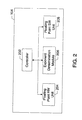
- FIG. 2 is a more detailed block diagram of a CPU illustrated in FIG. 1.
- FIG. 3 is a flowchart of a process for determining a ‘true’ floating-point exponent associated with an underflow condition or an overflow condition.
- In general, the methods and apparatus described herein determine a floating-point exponent associated with an underflow condition or an overflow condition. When a floating-point hardware unit encounters an underflow condition or an overflow condition, the methods and apparatus determine the ‘true’ value of the floating-point exponent of the result based on a truncated value of the floating-point exponent passed from the floating-point hardware unit to an exponent determination module. The determined value of the floating-point exponent may then be passed to a floating-point software unit for additional floating-point calculations, if necessary. If the floating-point hardware unit does not encounter an underflow condition or an overflow condition, the floating-point hardware unit and/or the floating-point software unit preferably performs the floating-point operation without the assistance of the exponent determination module.
- A block diagram of a
computer system 100 is illustrated in FIG. 1. Thecomputer system 100 may be a personal computer (PC), a personal digital assistant (PDA), an Internet appliance, a cellular telephone, or any other computing device. In this example, thecomputer system 100 includes amain processing unit 102 powered by apower supply 103. Themain processing unit 102 may include one or more central processing units (CPUs) 104 electrically coupled by asystem interconnect 106 to one or more memory device(s) 108 and one ormore interface circuits 110. In this example, thesystem interconnect 106 is an address/data bus. Of course, a person of ordinary skill in the art will readily appreciate that interconnects other than busses may be used to connect the CPU(s) 104 to the memory device(s) 108. For example, one or more dedicated lines and/or a crossbar may be used to connect the CPU(s) 104 to the memory device(s) 108. - The CPU(s) 104 may include any type of well known microprocessor, such as a microprocessor from the Intel Pentium™ family of microprocessors, the Intel Itanium™ family of microprocessors, and/or the Intel XScale™ family of processors. The
main memory device 108 may include dynamic random access memory (DRAM), but may also include nonvolatile memory. In this example, the memory device(s) 108 store a software program which is executed by one or more of the CPU(s) 104 in a well known manner. - The interface circuit(s) 110 may be implemented using any type of well known interface standard, such as an Ethernet interface and/or a Universal Serial Bus (USB) interface. One or
more input devices 112 may be connected to theinterface circuits 110 for entering data and commands into themain processing unit 102. For example, aninput device 112 may be a keyboard, mouse, touch screen, track pad, track ball, isopoint, and/or a voice recognition system. - One or more displays, printers, speakers, and/or
other output devices 114 may also be connected to themain processing unit 102 via one or more of theinterface circuits 110. Thedisplay 114 may be a cathode ray tube (CRT), a liquid crystal display (LCD), or any other type of display. Thedisplay 114 may generate visual indications of data generated during operation of themain processing unit 102. The visual displays may include prompts for human operator input, calculated values, detected data, etc. - The
computer system 100 may also include one ormore storage devices 116. For example, thecomputer system 100 may include one or more hard drives, a compact disk (CD) drive, a digital versatile disk drive (DVD), and/or other computer media input/output (I/O) devices. - The
computer system 100 may also exchange data with other devices via a connection to anetwork 118. The network connection may be any type of network connection, such as an Ethernet connection, digital subscriber line (DSL), telephone line, coaxial cable, etc. Thenetwork 118 may be any type of network, such as the Internet, a telephone network, a cable network, and/or a wireless network. - A more detailed block diagram of the
CPU 104 is illustrated in FIG. 2. Preferably, theCPU 104 includes acontroller 202, a floating-point hardware unit 204, anexponent determination module 206, and a floating-point software unit 208. The floating-point hardware unit 204 may be implemented by conventional electronic circuitry in a well known manner. The floating-point software unit 208 may be implemented by a microprocessor executing software instructions in a well known manner. Thecontroller 202 and theexponent determination module 206 may be implemented by a microprocessor executing software instructions and/or conventional electronic circuitry. In addition, a person of ordinary skill in the art will readily appreciate that certain modules may be combined or divided according to customary design constraints. Still further, one or more of these modules 202-208 may be located external to theCPU 104. - For the purpose of controlling the interaction of the floating-
point hardware unit 204, theexponent determination module 206, and the floating-point software unit 208, theCPU 104 includes acontroller 202. Thecontroller 202 is operatively coupled to the floating-point hardware unit 204, theexponent determination module 206, and the floating-point software unit 208 in a well known manner. For example, one set of software instructions may be operatively coupled to another set of software instructions via a subroutine call, parameter passing, and/or shared memory location(s). In another example, one piece of electronic circuitry may be operatively coupled to another piece of electronic circuitry via electrical signal line(s) such as a bus. In yet another example, a set of software instructions may be operatively coupled to a piece of electronic circuitry via electrical signal line(s) stimulated by a microprocessor executing the software instructions. In one example, thecontroller 202, theexponent determination module 206, and/or the floating-point software unit 208 are implemented by theCPU 104 executing software instructions. - For the purpose of performing one or more floating-point operations, the
CPU 104 includes a floating-point hardware unit 204. The floating-point hardware unit 208 is a well known circuit capable of quickly performing one or more predetermined floating-point operations. However, the range of the floating-point hardware unit 208 is inherently limited by some predetermined number of bits used to represent the floating-point numbers used in the floating-point operations. - Floating-point numbers are represented in scientific notation (e.g., 1.01×2 3). Accordingly, a floating-point number includes a sign (e.g., positive), a significand (e.g., 1.01), a base (e.g., 2) and an exponent (e.g., 3). In a binary floating-point system, a sign bit of ‘0’ denotes a positive value and a sign bit of ‘1’ denotes a negative value. Typically, a bias is added to the value of each exponent to facilitate a range of positive and negative numbers. For example, a bias of 0xffff may be added to a 17 bit exponent as is well known. In a binary system, a base of 2 is presumed and not stored. In many binary floating-point systems, numbers are stored and/or manipulated in ‘normalized’ form (i.e., the radix point is located immediately after the first non-zero digit). In such an instance, a leading ‘1’ may be presumed and not stored (e.g., as in IEEE-754).
- When floating-point numbers are used in mathematical operations, the result of the operation may be too large or too small to be represented by the floating-point system. When the result is too large to be represented by the floating-point system, an ‘overflow’ condition occurs. When the result is too small to be represented by the floating-point system, an ‘underflow’ condition occurs. An overflow condition occurs when the exact result in absolute value is larger than 1.11 . . . 1*2{circumflex over ( )} emax. An underflow condition occurs when the exact result in absolute value is smaller than 1.00 . . . 0*2{circumflex over ( )} emin.
- In order to calculate the ‘true’ value of the exponent in an overflow or an underflow situation, the
CPU 104 includes anexponent determination module 206. In order to facilitate software determination of the ‘true’ value of the exponent, the illustrated floating-point hardware unit 204 passes a truncated version of the exponent to theexponent determination module 206. In other words, the biased exponent passed from the floating-point hardware unit 204 to theexponent determination module 206 is missing the most significant bit (i.e., truncated) because the floating-point hardware unit 204 is not capable of handling all the bits in the exponent of the floating-point result. - For the purpose of performing one or more floating-point operations, the
CPU 104 also includes a floating-point software unit 208. Preferably, the floating-point software unit 208 is capable of handling larger and/or smaller floating-point results than the floating-point hardware unit 204. However, the floating-point software unit 208 is typically slower than the floating-point hardware unit 204. - A flowchart of a
process 300 for determining a ‘true’ floating-point exponent associated with an underflow condition or an overflow condition is illustrated in FIG. 3. Preferably, theprocess 300 is embodied in a software program which is stored in thememory 108 and executed by theCPU 104 in a well known manner. However, some or all of the components of theprocess 300 may be performed by another device. Although theprocess 300 is described with reference to the flowchart illustrated in FIG. 3, a person of ordinary skill in the art will readily appreciate that many other methods of performing the acts associated withprocess 300 may be used. For example, the order of many of the blocks may be changed, and many of the blocks described are optional. - Generally, the
process 300 causes theCPU 104 to determine the ‘true’ value of a floating-point exponent based on a truncated value of the floating-point exponent passed from the floating-point hardware unit 204 to theexponent determination module 206 when the floating-point hardware unit 204 encounters an underflow condition or an overflow condition. The determined value of the floating-point exponent is then passed to the floating-point software unit 208 for additional floating-point calculations, if necessary. If the floating-point hardware unit 204 does not encounter an underflow condition or an overflow condition, the floating-point hardware unit 204 and/or the floating-point software unit 208 preferably perform the floating-point operation without the assistance of theexponent determination module 206. - In the example illustrated in FIG. 3, the
process 300 begins by performing a floating-point operation using the floating-point hardware unit 204 (block 302). The result of the floating-point operation may or may not ‘fit’ within the number of bits the floating-point hardware unit 204 is structured to handle. Specifically, the exponent of the floating-point result may be too large (i.e., overflow), too small (i.e., underflow), or within the range the floating-point hardware unit 204 is structured to store. Accordingly, theprocess 300 causes theCPU 104 to test if an overflow condition occurred as a result of the floating-point operation performed by the floating-point hardware unit 204 (block 304). If an overflow condition did not occur, theprocess 300 causes theCPU 104 to test if an underflow condition occurred as a result of the floating-point operation (block 306). If neither an overflow condition nor an underflow condition occurred, theprocess 300 optionally causes theCPU 104 to remove the floating-point bias (e.g., for 17 bit exponents subtract 0xffff from the hardware result) (block 308) and use the result of the floating-point hardware unit 204 in any subsequent calculations and/or memory storage operations (block 310). - If an overflow did occur (block 304), the
process 300 preferably causes theCPU 104 to receive the biased/truncated exponent from the floating-point hardware unit 204 (block 312). Subsequently, theprocess 300 preferably causes theCPU 104 to subtract an “overflow shifting constant” from the biased/truncated exponent (block 314). The value of the overflow shifting constant (e.g., for 17 bit exponents 0x1007f) may depend on the number of bits used by the floating-point hardware unit 204 to represent floating-point exponents (e.g., 17) and/or the bias used by the floating-point standard (e.g., for 17 bit exponents 0xffff). Specifically, the value of the overflow shifting constant is selected to shift the range of the true biased exponent to make that range start at 0x0. - After the biased/truncated exponent is shifted by the overflow shifting constant, the shifted value is preferably truncated to the same number of bits used by the floating-
point hardware unit 204 to represent floating-point exponents (e.g., 17 bits) (block 316). For example, the value may be logically-ANDed with a mask containing 1s in the least significant N bits and 0s in the remaining bits (e.g., for 17 bit exponents 0x1ffff), where N is equal to the number of bits used by the floating-point hardware unit 204 to represent floating-point exponents (e.g., 17). Alternatively, a mod 2{circumflex over ( )}N operation may be performed on the shifted value to truncate the value to the least significant N bits. - Subsequently, the
process 300 preferably causes theCPU 104 to add the overflow shifting constant back into the current value of the calculation (block 318). Again, the value of the overflow shifting constant (e.g., for 17 bit exponents 0x1007f) may depend on the number of bits used by the floating-point hardware unit 204 to represent floating-point exponents (e.g., 17) and/or the bias used by the floating-point standard (e.g., for 17 bit exponents 0x0ffff). In addition, theprocess 300 causes theCPU 104 to remove the bias (e.g., for 17 bit exponents subtract 0x0ffff) (block 320). Finally, theCPU 104 may use the corrected result in subsequent calculations (block 322). For example, the floating-point value with the ‘true’ exponent may be used by the floating-point software unit 208 in additional floating-point calculations, and/or the value may be scaled down based on the computational model being used (e.g., IEEE Standard for Binary Floating-Point Arithmetic—ANSI/IEEE Standard 754-1985 single precision, double precision, etc.). - If an underflow condition occurs (block 306), the
process 300 preferably causes theCPU 104 to receive the biased/truncated exponent from the floating-point hardware unit 204 (block 324). Subsequently, theprocess 300 preferably causes theCPU 104 to add an “underflow shifting constant” to the biased/truncated exponent (block 326). The value of the underflow shifting constant (e.g., for 17 bit exponents 0x1007b) may depend on the number of bits used by the floating-point hardware unit 204 to represent floating-point exponents (e.g., 17) and/or the bias used by the floating-point standard (e.g., for 17 bit exponents 0x0ffff). Specifically, the value of the underflow shifting constant is selected to shift the range of the true biased exponent to make that range start at 0x0. - After the biased/truncated exponent is shifted by the underflow shifting constant, the shifted value is preferably truncated to the same number of bits used by the floating-
point hardware unit 204 to represent floating-point exponents (e.g., 17 bits) (block 328). For example, the value may be logically-ANDed with a mask containing 1s in the least significant N bits and 0s in the remaining bits (e.g., for 17 bit exponents 0x1ffff), where N is equal to the number of bits used by the floating-point hardware unit 204 to represent floating-point exponents (e.g., 17). Alternatively, a mod 2{circumflex over ( )}N operation may be performed on the shifted value to truncate the value to the least significant N bits. - Subsequently, the
process 300 preferably causes theCPU 104 to subtract the underflow shifting constant back out of the current value of the calculation (block 330). Again, the value of the underflow shifting constant (e.g., for 17 bit exponents 0x1007b) may depend on the number of bits used by the floating-point hardware unit 204 to represent floating-point exponents (e.g., 17) and/or the bias used by the floating-point standard (e.g., for 17 bit exponents 0x0ffff). In addition, theprocess 300 causes theCPU 104 to remove the bias (e.g., for 17 bit exponents subtract 0x0ffff) (block 320). Finally, theCPU 104 may use the corrected result in subsequent calculations (block 322). For example, the floating-point value with the ‘true’ exponent may be used by the floating-point software unit 208 in additional floating-point calculations, and/or the value may be scaled up based on the computational model being used (e.g., IEEE 754-1985 single precision, double precision, etc.). - In summary, persons of ordinary skill in the art will readily appreciate that methods and apparatus for determining a floating-point exponent associated with an underflow condition or an overflow condition have been provided. Systems implementing the teachings described herein may benefit from decreased hardware costs associated with an underflow bit and/or an overflow bit.
- The foregoing description has been presented for the purposes of illustration and description. It is not intended to be exhaustive or to limit the invention to the examples disclosed. Many modifications and variations are possible in light of the above teachings. It is intended that the scope of the invention be limited not by this detailed description of examples, but rather by the claims appended hereto.
Claims (29)
Priority Applications (1)
| Application Number | Priority Date | Filing Date | Title |
|---|---|---|---|
| US10/118,349 US7272623B2 (en) | 2002-04-08 | 2002-04-08 | Methods and apparatus for determining a floating-point exponent associated with an underflow condition or an overflow condition |
Applications Claiming Priority (1)
| Application Number | Priority Date | Filing Date | Title |
|---|---|---|---|
| US10/118,349 US7272623B2 (en) | 2002-04-08 | 2002-04-08 | Methods and apparatus for determining a floating-point exponent associated with an underflow condition or an overflow condition |
Publications (2)
| Publication Number | Publication Date |
|---|---|
| US20030191787A1 true US20030191787A1 (en) | 2003-10-09 |
| US7272623B2 US7272623B2 (en) | 2007-09-18 |
Family
ID=28674406
Family Applications (1)
| Application Number | Title | Priority Date | Filing Date |
|---|---|---|---|
| US10/118,349 Active 2024-06-26 US7272623B2 (en) | 2002-04-08 | 2002-04-08 | Methods and apparatus for determining a floating-point exponent associated with an underflow condition or an overflow condition |
Country Status (1)
| Country | Link |
|---|---|
| US (1) | US7272623B2 (en) |
Cited By (2)
| Publication number | Priority date | Publication date | Assignee | Title |
|---|---|---|---|---|
| US20040122885A1 (en) * | 2002-12-23 | 2004-06-24 | Cornea-Hasegan Marius A. | Method and system for avoiding underflow in a floating-point operation |
| US20060265443A1 (en) * | 2005-05-19 | 2006-11-23 | Cornea-Hasegan Marius A | Converting a number from a first base to a second base |
Families Citing this family (2)
| Publication number | Priority date | Publication date | Assignee | Title |
|---|---|---|---|---|
| US6963894B2 (en) * | 2002-04-08 | 2005-11-08 | Intel Corporation | Methods and apparatus for predicting an underflow condition associated with a floating-point multiply-add operation |
| US8327120B2 (en) | 2007-12-29 | 2012-12-04 | Intel Corporation | Instructions with floating point control override |
Citations (4)
| Publication number | Priority date | Publication date | Assignee | Title |
|---|---|---|---|---|
| US4647401A (en) * | 1983-01-24 | 1987-03-03 | Rhone Poulenc Inc. | Process for preparing colloidal ceric oxide and complexes thereof with free organic acids |
| US5892697A (en) * | 1995-12-19 | 1999-04-06 | Brakefield; James Charles | Method and apparatus for handling overflow and underflow in processing floating-point numbers |
| US20030041081A1 (en) * | 2001-05-25 | 2003-02-27 | Sun Microsystems, Inc. | System and method for performing floating point operations involving extended exponents |
| US6571265B1 (en) * | 1999-10-29 | 2003-05-27 | Intel Corporation | Mechanism to detect IEEE underflow exceptions on speculative floating-point operations |
-
2002
- 2002-04-08 US US10/118,349 patent/US7272623B2/en active Active
Patent Citations (4)
| Publication number | Priority date | Publication date | Assignee | Title |
|---|---|---|---|---|
| US4647401A (en) * | 1983-01-24 | 1987-03-03 | Rhone Poulenc Inc. | Process for preparing colloidal ceric oxide and complexes thereof with free organic acids |
| US5892697A (en) * | 1995-12-19 | 1999-04-06 | Brakefield; James Charles | Method and apparatus for handling overflow and underflow in processing floating-point numbers |
| US6571265B1 (en) * | 1999-10-29 | 2003-05-27 | Intel Corporation | Mechanism to detect IEEE underflow exceptions on speculative floating-point operations |
| US20030041081A1 (en) * | 2001-05-25 | 2003-02-27 | Sun Microsystems, Inc. | System and method for performing floating point operations involving extended exponents |
Cited By (4)
| Publication number | Priority date | Publication date | Assignee | Title |
|---|---|---|---|---|
| US20040122885A1 (en) * | 2002-12-23 | 2004-06-24 | Cornea-Hasegan Marius A. | Method and system for avoiding underflow in a floating-point operation |
| US7593977B2 (en) | 2002-12-23 | 2009-09-22 | Intel Corporation | Method and system for avoiding underflow in a floating-point operation |
| US20060265443A1 (en) * | 2005-05-19 | 2006-11-23 | Cornea-Hasegan Marius A | Converting a number from a first base to a second base |
| US7707233B2 (en) | 2005-05-19 | 2010-04-27 | Intel Corporation | Coverting a number from a first base to a second base |
Also Published As
| Publication number | Publication date |
|---|---|
| US7272623B2 (en) | 2007-09-18 |
Similar Documents
| Publication | Publication Date | Title |
|---|---|---|
| US8868632B2 (en) | Methods and apparatus for predicting an underflow condition associated with a floating-point multiply-add operation | |
| US8595279B2 (en) | Floating-point processor with reduced power requirements for selectable subprecision | |
| JP5175379B2 (en) | Floating point processor with selectable lower precision | |
| US9268528B2 (en) | System and method for dynamically reducing power consumption of floating-point logic | |
| US9465578B2 (en) | Logic circuitry configurable to perform 32-bit or dual 16-bit floating-point operations | |
| JP2021525403A (en) | Improved low precision binary floating point formatting | |
| CN1928809A (en) | System, apparatus and method for performing floating-point operations | |
| US8126954B2 (en) | Method and system for avoiding underflow in a floating-point operation | |
| US8291003B2 (en) | Supporting multiple formats in a floating point processor | |
| US10747501B2 (en) | Providing efficient floating-point operations using matrix processors in processor-based systems | |
| JP3313560B2 (en) | Floating point processor | |
| EP0529101A1 (en) | Floating-point dividing circuit | |
| US7272623B2 (en) | Methods and apparatus for determining a floating-point exponent associated with an underflow condition or an overflow condition | |
| US10338889B2 (en) | Apparatus and method for controlling rounding when performing a floating point operation | |
| US20140244704A1 (en) | Fused multiply add pipeline | |
| US6298365B1 (en) | Method and system for bounds comparator | |
| JPH05241787A (en) | Discrimination device for sticky bit value in arithmetic operation | |
| Tsen et al. | A combined decimal and binary floating-point multiplier | |
| JPH02294731A (en) | Floating point arithmetic processor | |
| CN109901813A (en) | A kind of floating-point operation device and method | |
| US8250126B2 (en) | Efficient leading zero anticipator | |
| JP2517064B2 (en) | Denormalized number processing method | |
| US9335967B1 (en) | Accurate floating-point calculation method and device | |
| JPS61141034A (en) | Calculating device of arithmetic result limit | |
| KR20040033198A (en) | Floating point with multiply-add unit |
Legal Events
| Date | Code | Title | Description |
|---|---|---|---|
| AS | Assignment |
Owner name: INTEL CORPORATION, CALIFORNIA Free format text: ASSIGNMENT OF ASSIGNORS INTEREST;ASSIGNOR:CORNEA-HASEGAN, MARIUS A.;REEL/FRAME:013047/0831 Effective date: 20020619 |
|
| STCF | Information on status: patent grant |
Free format text: PATENTED CASE |
|
| CC | Certificate of correction | ||
| FPAY | Fee payment |
Year of fee payment: 4 |
|
| AS | Assignment |
Owner name: MICRON TECHNOLOGY, INC., IDAHO Free format text: ASSIGNMENT OF ASSIGNORS INTEREST;ASSIGNOR:INTEL CORPORATION;REEL/FRAME:030747/0001 Effective date: 20111122 |
|
| FPAY | Fee payment |
Year of fee payment: 8 |
|
| AS | Assignment |
Owner name: U.S. BANK NATIONAL ASSOCIATION, AS COLLATERAL AGENT, CALIFORNIA Free format text: SECURITY INTEREST;ASSIGNOR:MICRON TECHNOLOGY, INC.;REEL/FRAME:038669/0001 Effective date: 20160426 Owner name: U.S. BANK NATIONAL ASSOCIATION, AS COLLATERAL AGEN Free format text: SECURITY INTEREST;ASSIGNOR:MICRON TECHNOLOGY, INC.;REEL/FRAME:038669/0001 Effective date: 20160426 |
|
| AS | Assignment |
Owner name: MORGAN STANLEY SENIOR FUNDING, INC., AS COLLATERAL AGENT, MARYLAND Free format text: PATENT SECURITY AGREEMENT;ASSIGNOR:MICRON TECHNOLOGY, INC.;REEL/FRAME:038954/0001 Effective date: 20160426 Owner name: MORGAN STANLEY SENIOR FUNDING, INC., AS COLLATERAL Free format text: PATENT SECURITY AGREEMENT;ASSIGNOR:MICRON TECHNOLOGY, INC.;REEL/FRAME:038954/0001 Effective date: 20160426 |
|
| AS | Assignment |
Owner name: U.S. BANK NATIONAL ASSOCIATION, AS COLLATERAL AGENT, CALIFORNIA Free format text: CORRECTIVE ASSIGNMENT TO CORRECT THE REPLACE ERRONEOUSLY FILED PATENT #7358718 WITH THE CORRECT PATENT #7358178 PREVIOUSLY RECORDED ON REEL 038669 FRAME 0001. ASSIGNOR(S) HEREBY CONFIRMS THE SECURITY INTEREST;ASSIGNOR:MICRON TECHNOLOGY, INC.;REEL/FRAME:043079/0001 Effective date: 20160426 Owner name: U.S. BANK NATIONAL ASSOCIATION, AS COLLATERAL AGEN Free format text: CORRECTIVE ASSIGNMENT TO CORRECT THE REPLACE ERRONEOUSLY FILED PATENT #7358718 WITH THE CORRECT PATENT #7358178 PREVIOUSLY RECORDED ON REEL 038669 FRAME 0001. ASSIGNOR(S) HEREBY CONFIRMS THE SECURITY INTEREST;ASSIGNOR:MICRON TECHNOLOGY, INC.;REEL/FRAME:043079/0001 Effective date: 20160426 |
|
| AS | Assignment |
Owner name: JPMORGAN CHASE BANK, N.A., AS COLLATERAL AGENT, ILLINOIS Free format text: SECURITY INTEREST;ASSIGNORS:MICRON TECHNOLOGY, INC.;MICRON SEMICONDUCTOR PRODUCTS, INC.;REEL/FRAME:047540/0001 Effective date: 20180703 Owner name: JPMORGAN CHASE BANK, N.A., AS COLLATERAL AGENT, IL Free format text: SECURITY INTEREST;ASSIGNORS:MICRON TECHNOLOGY, INC.;MICRON SEMICONDUCTOR PRODUCTS, INC.;REEL/FRAME:047540/0001 Effective date: 20180703 |
|
| AS | Assignment |
Owner name: MICRON TECHNOLOGY, INC., IDAHO Free format text: RELEASE BY SECURED PARTY;ASSIGNOR:U.S. BANK NATIONAL ASSOCIATION, AS COLLATERAL AGENT;REEL/FRAME:047243/0001 Effective date: 20180629 |
|
| MAFP | Maintenance fee payment |
Free format text: PAYMENT OF MAINTENANCE FEE, 12TH YEAR, LARGE ENTITY (ORIGINAL EVENT CODE: M1553); ENTITY STATUS OF PATENT OWNER: LARGE ENTITY Year of fee payment: 12 |
|
| AS | Assignment |
Owner name: MICRON TECHNOLOGY, INC., IDAHO Free format text: RELEASE BY SECURED PARTY;ASSIGNOR:MORGAN STANLEY SENIOR FUNDING, INC., AS COLLATERAL AGENT;REEL/FRAME:050937/0001 Effective date: 20190731 |
|
| AS | Assignment |
Owner name: MICRON SEMICONDUCTOR PRODUCTS, INC., IDAHO Free format text: RELEASE BY SECURED PARTY;ASSIGNOR:JPMORGAN CHASE BANK, N.A., AS COLLATERAL AGENT;REEL/FRAME:051028/0001 Effective date: 20190731 Owner name: MICRON TECHNOLOGY, INC., IDAHO Free format text: RELEASE BY SECURED PARTY;ASSIGNOR:JPMORGAN CHASE BANK, N.A., AS COLLATERAL AGENT;REEL/FRAME:051028/0001 Effective date: 20190731 |