US20030195720A1 - Methods and apparatus for engine diagnostics - Google Patents
Methods and apparatus for engine diagnostics Download PDFInfo
- Publication number
- US20030195720A1 US20030195720A1 US10/436,792 US43679203A US2003195720A1 US 20030195720 A1 US20030195720 A1 US 20030195720A1 US 43679203 A US43679203 A US 43679203A US 2003195720 A1 US2003195720 A1 US 2003195720A1
- Authority
- US
- United States
- Prior art keywords
- accordance
- engine
- processor
- display
- memory
- Prior art date
- Legal status (The legal status is an assumption and is not a legal conclusion. Google has not performed a legal analysis and makes no representation as to the accuracy of the status listed.)
- Abandoned
Links
Images


Classifications
-
- F—MECHANICAL ENGINEERING; LIGHTING; HEATING; WEAPONS; BLASTING
- F02—COMBUSTION ENGINES; HOT-GAS OR COMBUSTION-PRODUCT ENGINE PLANTS
- F02D—CONTROLLING COMBUSTION ENGINES
- F02D41/00—Electrical control of supply of combustible mixture or its constituents
-
- F—MECHANICAL ENGINEERING; LIGHTING; HEATING; WEAPONS; BLASTING
- F01—MACHINES OR ENGINES IN GENERAL; ENGINE PLANTS IN GENERAL; STEAM ENGINES
- F01P—COOLING OF MACHINES OR ENGINES IN GENERAL; COOLING OF INTERNAL-COMBUSTION ENGINES
- F01P3/00—Liquid cooling
- F01P3/12—Arrangements for cooling other engine or machine parts
-
- F—MECHANICAL ENGINEERING; LIGHTING; HEATING; WEAPONS; BLASTING
- F02—COMBUSTION ENGINES; HOT-GAS OR COMBUSTION-PRODUCT ENGINE PLANTS
- F02D—CONTROLLING COMBUSTION ENGINES
- F02D41/00—Electrical control of supply of combustible mixture or its constituents
- F02D41/22—Safety or indicating devices for abnormal conditions
-
- H—ELECTRICITY
- H05—ELECTRIC TECHNIQUES NOT OTHERWISE PROVIDED FOR
- H05K—PRINTED CIRCUITS; CASINGS OR CONSTRUCTIONAL DETAILS OF ELECTRIC APPARATUS; MANUFACTURE OF ASSEMBLAGES OF ELECTRICAL COMPONENTS
- H05K5/00—Casings, cabinets or drawers for electric apparatus
- H05K5/0026—Casings, cabinets or drawers for electric apparatus provided with connectors and printed circuit boards [PCB], e.g. automotive electronic control units
-
- F—MECHANICAL ENGINEERING; LIGHTING; HEATING; WEAPONS; BLASTING
- F01—MACHINES OR ENGINES IN GENERAL; ENGINE PLANTS IN GENERAL; STEAM ENGINES
- F01P—COOLING OF MACHINES OR ENGINES IN GENERAL; COOLING OF INTERNAL-COMBUSTION ENGINES
- F01P2050/00—Applications
- F01P2050/30—Circuit boards
-
- F—MECHANICAL ENGINEERING; LIGHTING; HEATING; WEAPONS; BLASTING
- F02—COMBUSTION ENGINES; HOT-GAS OR COMBUSTION-PRODUCT ENGINE PLANTS
- F02D—CONTROLLING COMBUSTION ENGINES
- F02D2400/00—Control systems adapted for specific engine types; Special features of engine control systems not otherwise provided for; Power supply, connectors or cabling for engine control systems
- F02D2400/18—Packaging of the electronic circuit in a casing
-
- F—MECHANICAL ENGINEERING; LIGHTING; HEATING; WEAPONS; BLASTING
- F02—COMBUSTION ENGINES; HOT-GAS OR COMBUSTION-PRODUCT ENGINE PLANTS
- F02D—CONTROLLING COMBUSTION ENGINES
- F02D41/00—Electrical control of supply of combustible mixture or its constituents
- F02D41/24—Electrical control of supply of combustible mixture or its constituents characterised by the use of digital means
- F02D41/26—Electrical control of supply of combustible mixture or its constituents characterised by the use of digital means using computer, e.g. microprocessor
- F02D41/266—Electrical control of supply of combustible mixture or its constituents characterised by the use of digital means using computer, e.g. microprocessor the computer being backed-up or assisted by another circuit, e.g. analogue
Definitions
- This invention relates generally to engines and, more particularly, to performing engine diagnostics using a computer.
- ECU electronice control unit
- engine components such as the engine ignition, lubrication pumps, water circulation system (if any) and fuel injectors.
- the ECU controls timing of the engine ignition and fuel injection in accordance with a pre-programmed control program.
- an external computer can be coupled to a communications port of the ECU.
- a diagnostic program implemented in computer software such as the BMCA FFI engine diagnostic software available from Bombardier Motor Corporation of America, Waukegan, Ill., is loaded in the external computer.
- Fault codes stored in the ECU memory are read by the external computer, and the fault codes are indicative of certain messages that are then displayed to the operator.
- an operator may input commands via a keyboard of the computer and/or touch screen, and based on the operator inputs, the external computer instructs the ECU to run diagnostic tests on the engine.
- the present invention in one aspect, is a method for operating a computer to display text messages in any one of a plurality of selectable languages.
- Text files for each selectable language are stored in the non-volatile memory of the computer, and based on an operator selection, text files corresponding to the selected language are copied from non-volatile memory to the computer random access memory (RAM).
- the text files in RAM are utilized by the computer processor to generate screen displays.
- a typical computer includes a processor, a random access memory (RAM), and a non-volatile memory such as a read only memory (ROM).
- RAM random access memory
- ROM read only memory
- the RAM and the ROM are coupled to the processor.
- Text files corresponding to various selectable languages are stored in ROM, and a default language is copied from ROM into RAM.
- the processor after start-up of the computer and initialization of the program, generates screen displays using the text file stored in RAM.
- the diagnostic software improves the display of air temperature, water temperature, ECU temperature, ignition duration and TPS actual values when connected to a water cooled ECU.
- the diagnostic software allows starting of software with the engine at running speed, provides a full-service report, permits copying of engine-specific information from an original ECU into a service replacement ECU, and enables fuel injector serial numbers to be identified.
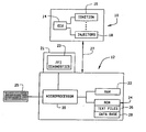
- FIG. 1 is a block diagram of an engine and an external computer coupled to the engine.
- FIG. 2 illustrates an initial screen display for permitting an operator to select between a diagnostic program and a service utilities program.
- FIGS. 3 - 5 illustrate screen displays for enabling an operator to select operation of an engine diagnostic program in a desired language.
- FIGS. 6 - 10 illustrate screen displays associated with performing an ignition coil test.
- FIG. 11 illustrates an engine operation screen display.
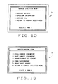
- FIGS. 12 and 13 are engine service utility screen displays.
- FIGS. 14 and 15 illustrate ECU printouts.
- FIGS. 16 and 17 illustrate injector information screen displays.
- FIGS. 18 - 21 illustrate ECU service screen displays.
- the present invention is sometimes described herein in the context of performing diagnostic tests on an outboard engine, the present invention can be utilized in connection with diagnostic tests for many different types of engines, including automobile engines.
- the present invention is described herein in connection with an engine that includes fuel injection, the invention can be utilized in connection with engines that include any one of a wide variety of fuel injection mechanisms, electrically powered engines and in engines that include other fuel or energy supply systems.
- the methods and apparatus for enabling operator selection of a language as described herein can be utilized in many different applications in addition to diagnostic testing.
- the present invention is not limited to use in connection with only outboard engine diagnostic test operations.
- FIG. 1 is a block diagram of an engine 10 and an external computer 12 coupled to engine 10 .
- Engine 10 is, in one embodiment, an internal combustion engine including fuel injection, such as an Evinrude outboard engine commercially available from Bombardier Motor Corporation of America, Waukegan, Ill. As explained above, engine 10 may be an automobile engine, or any other type of engine which can benefit from the use of diagnostic software.
- Engine 10 includes an electronic control unit (ECU) 14 coupled to engine components such as engine ignition 16 and fuel injectors 18 , which can be conventional or non-conventional.
- ECU 14 controls operation of engine 10 and provides information to the operator by controlling various indicator lights in gauges.
- ECU 14 controls operation of engine 10 by, for example, controlling firing of spark plugs via ignition 16 and controlling supply of fuel to the engine cylinders via injectors 18 .
- Computer 12 is a diagnostic computer that is coupled by a command/data link 27 to ECU 14 for use by a diagnostic operator or repairman for servicing engine 10 .
- Computer 12 includes a microprocessor 20 coupled to a random access memory (RAM) 22 and a read only memory (ROM) 24 .
- Computer 12 also has a monitor 21 with a display screen 23 .
- computer 12 is a battery-powered laptop computer, and processor 20 is a 286 MHz MSDOS processor. Of course, other operating systems such as MacOS, Linux or Windows NT could be used. Likewise, higher speed processors such as 386 MHz, 486 MHz, Pentium, PentiumII, Cyrix, AMD, Celeron or other more modern processor may be used.
- ROM 24 includes, in one embodiment, at least 400 kilobytes of available memory. However, the required amount of memory depends upon the program in which the present invention is associated.
- Computer 12 also includes, for example, a monochromatic or color display 23 and a keyboard 25 for entry of user commands and data. Many other types and models of computers can be used, and the present invention is not limited to practice in connection with any one particular type of computer.
- Commands, programs and data are transmitted from microprocessor 20 to ECU 14 via link 27 .
- Commands, programs and data are transmitted from ECU 14 to processor 20 via link 27 .
- Programs may be sent only on start-up or may be sent periodically as various functions all are selected and activated.
- ROM 24 includes text files 26 and database files 28 .
- Files 26 and 28 are loaded into ROM from a CD, a high-capacity disk such as a “ZIP disk”, “JAZZ disk” or “Super Disk”, or just a standard floppy disk, e.g., a 1.44 Meg 31 ⁇ 2 inch floppy disk, depending primarily upon the size and complexity of the files 26 and 28 .
- Text files 26 contain the text for various screen displays to be shown on the display of computer 12 .
- the term “text files” is used, it will be understood that this term means any file containing data which can be read by computer 12 to cause the display of textual material, or screen displays, on display screen 23 .
- Database files 28 contain the fault codes and other information to be utilized in connection with diagnostic operations.
- the diagnostic software program Prior to operation, the diagnostic software program is loaded into computer 12 from, for example, a floppy disk.
- An install program is run to cause the diagnostic program, including text files and data bases, to be loaded into ROM 24 .
- sixteen text files are used for storing text associated with eight different languages such as, for example, English, Francais (French), Espanol (Spanish), Portuguese, Deutsch (German), Italiano (Italian), Swedish, and Finnish. Any multiple number of languages could be used.
- microprocessor 20 Upon initialization of the diagnostic program now stored in computer 12 , microprocessor 20 uploads from ROM 24 and into RAM 22 text files 26 having the screen display information in English, and causes a screen display 30 (shown in FIG. 2) to be shown on the display screen 23 .
- screen display 30 provides three options 1) (FFI DIAGONOSTICS), 2) (SERVICE UTILITIES) OR X (EXIT PROGRAM).
- processor 20 Upon receiving an input indicating that an operator has pressed a 1 key on keyboard 25 in response to the display 30 , processor 20 causes a screen display 50 as shown in FIG. 3 to be shown on the computer display. If the operator desires at this stage to configure the computer for a non-English language, the operator may enter a setup program by pushing the F3 key on keyboard 25 . Upon receiving an input indicating that an operator has pressed the F3 key on keyboard 25 , processor 20 then causes a screen display 52 as shown in FIG. 4 to be shown on the computer display. An operator can then select 1 (SELECT LANGUAGE), 2 (CHANGE COMM PORT), or x (EXIT SETUP) on keyboard 25 . If the operator selects a 1, then processor 20 causes a language selection screen display 54 as shown in FIG. 5 to be shown on display screen 23 .
- microprocessor 20 in response to operator commands, instructs ECU 14 to energize certain selected components to verify operation, e.g., to verify operation of ignition 16 and fuel injectors 18 .
- verifying operation of ignition 16 for example, a command from processor 20 causes ECU 14 to fire a respective ignition circuit, and the operator can observe whether the circuit does, in fact, fire.
- the portion of the ignition preceding the ignition coil is all in ECU 14 , so that ECU 14 may electrically determine if the ignition coil, is working properly. This allows the ECU to determine whether it is spark plugs or ignition coil that is causing any observed failure to fire.
- microprocessor 20 instructs ECU 14 to display various operating conditions of engine 10 .
- FIGS. 6 - 10 illustrate screen displays associated with performing an ignition coil test.
- processor 20 After performing the program set-up operations as described above, processor 20 causes main menu screen display 56 as shown in FIG. 6 to be displayed on the computer display. If, for example, the operator desires to perform a static test, the operator presses the 2 key on keyboard 25 . Upon receipt of data indicating the user selection, processor 20 executes the routine associated with the selected test.
- processor 20 upon receiving an input corresponding to the user selection of 2, causes a static testing menu screen display 58 as shown in FIG. 7 to be displayed. The operator can then select one of four tests by selecting 1-4, or can exit by selecting x. If the operator desires to test ignition firing, the operator selects 2. It will be understood that any number of static tests could be performed, and that the four tests shown in FIG. 7 are only exemplary.
- processor 20 Upon receipt of the user selection of 2, processor 20 causes a warning screen display 60 as shown in FIG. 8 to be displayed. The operator can then continue by either canceling the test by selecting ⁇ ESC>, or proceeding with the test by selecting any other key of keyboard 25 .
- processor 20 If processor 20 receives an input indicating that the operator desires to continue with testing, then processor 20 causes a message screen display 62 as shown in FIG. 9 to be displayed. The message instructs the operator to remove all spark plug leads and to connect the leads to a spark tester and to set the air gap. Once the operator has carried out the instructions, the operator continues by pressing any key of keyboard 25 .
- processor 20 Upon receipt of an input indicating that the operator has performed the instructed tasks, processor 20 then causes an ignition selection screen display 64 as shown in FIG. 10 to be displayed. The operator can then cause any of the ignition circuits to fire by selecting 1-6, or can exit by selecting x.
- the numbers 1-6 correspond to respective cylinders of a six cylinder engine. For example, if the operator selects 2, processor 20 communicates to ECU 14 that the ignition circuit, or coil, corresponding to cylinder #2 should fire. The operator can then observe whether a spark is generated by such ignition circuit by observing the spark tester after making the selection.
- the diagnostic software in one embodiment also provides a screen display 66 (shown in FIG. 11) of the operation the engine 10 divided into a sensor section 68 , a switches section 70 , a voltage section 72 and the results section 74 .
- Sensor section 68 displays air temperature, water temperature, ECU temperature, ignition duration, and TPS (throttle position sensor) actual and calculated values when connected to a water cooled ECU.
- TPS throttle position sensor
- section 68 displays not only the temperature in degrees Fahrenheit, but also the temperature in degrees Centigrade and the voltage output of the temperature sensor involved. This allows the diagnostic operator to determine if the sensor is working properly by checking to see if proper voltage signals are being provided by the sensors. This section 68 also allows the diagnostic operator to determine if the temperature of air, water and ECU are high or low.
- Section 70 provides indication of various switch conditions such as overheat, oil pressure within limits, shift interrupt or activated, water found in fuel, and whether or not the engine is in S.L.O.W.
- Section 72 provides the current voltage is for the alternator, both in the 12 volt and the 26/46 volt portions.
- Section 74 includes engine speed, ignition timing, spark duration, fuel injection timing, fuel pulse width and barometric pressure. The presence of all these conditions in a single screen display is of particular value to the diagnostic operator or service repairman.
- screen 74 (shown in FIG. 12) appears.
- This screen display 74 is the service utilities menu and allows the operator to select from four subprograms 1) SERVICE REPORTS, 2) INJECTOR INFORMATION, 3) SERVICE ECU, and 4) RETURN TO PROGRAM SELECTION MENU.
- the service report menu screen display 76 (shown in FIG. 13) will be displayed. This menu gives the operator six choices 1) VIEW CURRENT ECU REPORT, 2) SAVE CURRENT ECU REPORT, 3) PRINT CURRENT ECU REPORT, 4) VIEW SAVED REPORT, 5) PRINT SAVED REPORT, 6) RETURN TO SERVICE UTILITIES MENU. If the operator then presses key 1 of keyboard 25 , a very complete two-page ECU printout, as shown in FIG. 14 and FIG. 15, is provided.
- injectors information screen display 82 (shown in FIG. 16) is displayed on screen 23 .
- Screen display 82 provides the serial number of each injector for each cylinder of engine 10 . This allows the operator to verify that the proper type of injector is installed in engine 10 . If an incorrect injector, for example injector 1 , is detected, a replacement can be installed and the screen 82 will automatically indicate by a second screen display 84 (shown in FIG. 17) that such injector 1 has been replaced.
- screen display 74 (shown in FIG. 12) as described above, and presses key 3 on keyboard 25 to call screen display 86 (shown in FIG. 19) on display screen 23 .
- Screen display 86 is a warning screen that advises the operator of the operations that must be performed before the ECU can be replaced using the diagnostic software properly.
- the operator now confirms that the required operations have been performed and ECU 14 is ready to be replaced. Upon such confirmation, the operator presses any key of keyboard 25 to cause microprocessor 20 to transfer all of the specific ECU information from the replaced ECU into microprocessor 20 and, upon completion of such information transfer, to call up screen display 88 (shown in FIG. 20) indicating successful transfer.
- Screen display 88 further instructs the operator to now turn the ignition key off, replace the existing ECU with the replacement ECU, and turn the ignition key back on and then press any key the keyboard 25 .
- microprocessor 20 Upon sensing that a key has been pressed on keyboard 25 , microprocessor 20 now transfers the stored information from microprocessor 20 relative to the existing ECU into the replacement ECU and calls up screen display 90 (shown in FIG. 21) to indicate the successful completion of the information transfer from the existing ECU into the new replacement ECU.
Abstract
Description
- This application is a divisional application of U.S. application Ser. No. 09/430,228, filed Oct. 29, 1999, which claims the benefit of provisional U.S. patent application No. 60/134,326 filed May 14, 1999 and U.S. provisional patent application No. 60/109,716 filed Nov. 24, 1998.
- [0002] A portion of the disclosure of this patent document contains material that is subject to copyright protection. The copyright owner has no objection to the facsimile reproduction by anyone of the patent document or the patent disclosure, as it appears in the Patent and Trademark Office patent file or records, but otherwise reserves all copyright rights whatsoever.
- This invention relates generally to engines and, more particularly, to performing engine diagnostics using a computer.
- Many known internal combustion engines for use with watercraft include an electronic control unit (ECU) for controlling at least some operations of the engine. In a typical implementation, an ECU is electrically connected to engine components such as the engine ignition, lubrication pumps, water circulation system (if any) and fuel injectors. The ECU controls timing of the engine ignition and fuel injection in accordance with a pre-programmed control program.
- In order to determine whether an engine is operating properly, and to assist in diagnosing an engine failure, an external computer can be coupled to a communications port of the ECU. A diagnostic program implemented in computer software, such as the BMCA FFI engine diagnostic software available from Bombardier Motor Corporation of America, Waukegan, Ill., is loaded in the external computer. Fault codes stored in the ECU memory are read by the external computer, and the fault codes are indicative of certain messages that are then displayed to the operator. In addition, an operator may input commands via a keyboard of the computer and/or touch screen, and based on the operator inputs, the external computer instructs the ECU to run diagnostic tests on the engine.
- Outboard engines are sold in many different countries, and the diagnostic software interface should be capable of displaying text messages in at least one of many different languages. Generating many different software versions that display text messages in different respective languages can be costly. For example, tracking and delivering diagnostic software to many different customers worldwide in accordance with the language needs of each specific customer is burdensome and error prone.
- In addition to fault codes, other information such as engine speed, battery voltage and alternator voltage can be displayed on various separate screens. Use of these separate screens, however, can be cumbersome.
- Current diagnostic software requires the throttle to be reduced to idle in order to run the diagnostic software package. Current diagnostic software also does not provide a service report which can be printed immediately or saved in a computer. This leaves both the customer and repairmen with less than full information.
- Replacement of the ECU is complicated due to the need to customize the ECU to the particular engine. The need to customize the ECU makes it a time consuming repair operation and thus increases the cost to the customer of repairs involving replacement of the ECU.
- If the diagnostic software is used on engines having fuel injectors, there has previously been no way to verify that the ECU is customized to the proper fuel injectors except for running operational tests and determining if the fuel injectors are working properly.
- The present invention, in one aspect, is a method for operating a computer to display text messages in any one of a plurality of selectable languages. Text files for each selectable language are stored in the non-volatile memory of the computer, and based on an operator selection, text files corresponding to the selected language are copied from non-volatile memory to the computer random access memory (RAM). The text files in RAM are utilized by the computer processor to generate screen displays.
- More specifically, a typical computer includes a processor, a random access memory (RAM), and a non-volatile memory such as a read only memory (ROM). The RAM and the ROM are coupled to the processor. Text files corresponding to various selectable languages are stored in ROM, and a default language is copied from ROM into RAM. The processor, after start-up of the computer and initialization of the program, generates screen displays using the text file stored in RAM.
- If an operator desires to have the screen displays in one of the other selectable languages, then upon receipt of the appropriate command, the text file or files corresponding to the desired language are copied from ROM into RAM, and the processor then uses newly copied text files in RAM to generate the screen displays. As a result, the screen displays are in the user selected language.
- In addition to the language improvements, the diagnostic software, in one embodiment, improves the display of air temperature, water temperature, ECU temperature, ignition duration and TPS actual values when connected to a water cooled ECU.
- In one embodiment, the diagnostic software allows starting of software with the engine at running speed, provides a full-service report, permits copying of engine-specific information from an original ECU into a service replacement ECU, and enables fuel injector serial numbers to be identified.
- FIG. 1 is a block diagram of an engine and an external computer coupled to the engine.
- FIG. 2 illustrates an initial screen display for permitting an operator to select between a diagnostic program and a service utilities program.
- FIGS. 3-5 illustrate screen displays for enabling an operator to select operation of an engine diagnostic program in a desired language.
- FIGS. 6-10 illustrate screen displays associated with performing an ignition coil test.
- FIG. 11 illustrates an engine operation screen display.
- FIGS. 12 and 13 are engine service utility screen displays.
- FIGS. 14 and 15 illustrate ECU printouts.
- FIGS. 16 and 17 illustrate injector information screen displays.
- FIGS. 18-21 illustrate ECU service screen displays.
- Although the present invention is sometimes described herein in the context of performing diagnostic tests on an outboard engine, the present invention can be utilized in connection with diagnostic tests for many different types of engines, including automobile engines. For example, and although the present invention is described herein in connection with an engine that includes fuel injection, the invention can be utilized in connection with engines that include any one of a wide variety of fuel injection mechanisms, electrically powered engines and in engines that include other fuel or energy supply systems. In addition, the methods and apparatus for enabling operator selection of a language as described herein can be utilized in many different applications in addition to diagnostic testing. The present invention is not limited to use in connection with only outboard engine diagnostic test operations.
- FIG. 1 is a block diagram of an
engine 10 and anexternal computer 12 coupled toengine 10.Engine 10 is, in one embodiment, an internal combustion engine including fuel injection, such as an Evinrude outboard engine commercially available from Bombardier Motor Corporation of America, Waukegan, Ill. As explained above,engine 10 may be an automobile engine, or any other type of engine which can benefit from the use of diagnostic software. -
Engine 10 includes an electronic control unit (ECU) 14 coupled to engine components such asengine ignition 16 andfuel injectors 18, which can be conventional or non-conventional. Generally,ECU 14 controls operation ofengine 10 and provides information to the operator by controlling various indicator lights in gauges. ECU 14 controls operation ofengine 10 by, for example, controlling firing of spark plugs viaignition 16 and controlling supply of fuel to the engine cylinders viainjectors 18. -
Computer 12 is a diagnostic computer that is coupled by a command/data link 27 toECU 14 for use by a diagnostic operator or repairman forservicing engine 10.Computer 12 includes amicroprocessor 20 coupled to a random access memory (RAM) 22 and a read only memory (ROM) 24.Computer 12 also has amonitor 21 with adisplay screen 23. In one embodiment,computer 12 is a battery-powered laptop computer, andprocessor 20 is a 286 MHz MSDOS processor. Of course, other operating systems such as MacOS, Linux or Windows NT could be used. Likewise, higher speed processors such as 386 MHz, 486 MHz, Pentium, PentiumII, Cyrix, AMD, Celeron or other more modern processor may be used. Also,ROM 24 includes, in one embodiment, at least 400 kilobytes of available memory. However, the required amount of memory depends upon the program in which the present invention is associated.Computer 12 also includes, for example, a monochromatic orcolor display 23 and akeyboard 25 for entry of user commands and data. Many other types and models of computers can be used, and the present invention is not limited to practice in connection with any one particular type of computer. - Commands, programs and data are transmitted from
microprocessor 20 toECU 14 vialink 27. Commands, programs and data are transmitted fromECU 14 toprocessor 20 vialink 27. For some operations, only commands will be sent and for other operations only data will be sent. Programs may be sent only on start-up or may be sent periodically as various functions all are selected and activated. - As described hereinafter in more detail,
ROM 24 includes text files 26 and database files 28.Files files computer 12. Although the term “text files” is used, it will be understood that this term means any file containing data which can be read bycomputer 12 to cause the display of textual material, or screen displays, ondisplay screen 23. Database files 28 contain the fault codes and other information to be utilized in connection with diagnostic operations. - By having
text files 26 external separate from the program, no display text internal to the program is required, and there is no need to recompile the program just for a language change. That is, if an operator wants the screens displayed in a different language from the current language (e.g., the operator wants the screen displays in French rather than English), the operator simply follows the steps described below and the program then utilizes the text files corresponding to the selected language to generate screen displays. - Prior to operation, the diagnostic software program is loaded into
computer 12 from, for example, a floppy disk. An install program is run to cause the diagnostic program, including text files and data bases, to be loaded intoROM 24. In one specific exemplary embodiment, sixteen text files are used for storing text associated with eight different languages such as, for example, English, Francais (French), Espanol (Spanish), Portuguese, Deutsch (German), Italiano (Italian), Swedish, and Finnish. Any multiple number of languages could be used. - Upon initialization of the diagnostic program now stored in
computer 12,microprocessor 20 uploads fromROM 24 and intoRAM 22text files 26 having the screen display information in English, and causes a screen display 30 (shown in FIG. 2) to be shown on thedisplay screen 23. Although the default language in the embodiment described herein is English, the default language could be any one of the languages for which text files exist.Screen display 30 provides three options 1) (FFI DIAGONOSTICS), 2) (SERVICE UTILITIES) OR X (EXIT PROGRAM). - Upon receiving an input indicating that an operator has pressed a 1 key on
keyboard 25 in response to thedisplay 30,processor 20 causes ascreen display 50 as shown in FIG. 3 to be shown on the computer display. If the operator desires at this stage to configure the computer for a non-English language, the operator may enter a setup program by pushing the F3 key onkeyboard 25. Upon receiving an input indicating that an operator has pressed the F3 key onkeyboard 25,processor 20 then causes ascreen display 52 as shown in FIG. 4 to be shown on the computer display. An operator can then select 1 (SELECT LANGUAGE), 2 (CHANGE COMM PORT), or x (EXIT SETUP) onkeyboard 25. If the operator selects a 1, thenprocessor 20 causes a languageselection screen display 54 as shown in FIG. 5 to be shown ondisplay screen 23. - When
screen display 54 is being displayed on-screen 23, an operator can then select 1 (ENGLISH), 2 (FRANCAIS), 3 (ESPANOL), 4 (PORTUGUESE), 5 (GERMAN), 6 (ITALIAN), 7 (SWEDISH), 8 (FINNISH) or x (EXIT) onkeyboard 25. For example, if the operator selects 2, i.e., French, thenmicroprocessor 20 uploads fromROM 24 the text file(s) corresponding to French text intoRAM 22. That is, the text files from the selected language are copied over the text files currently stored inRAM 22.Processor 20 when generating screen displays then subsequently uses the most recently uploaded text files and returns the operator to screen display 50 (shown in FIG. 3). Upon pressing any key onkeyboard 25 whilescreen 50 is displaying,computer 12 displays the main menu screen display 56 (shown in FIG. 6). - Generally, and in some diagnostic testing operations,
microprocessor 20, in response to operator commands, instructsECU 14 to energize certain selected components to verify operation, e.g., to verify operation ofignition 16 andfuel injectors 18. In verifying operation ofignition 16, for example, a command fromprocessor 20 causesECU 14 to fire a respective ignition circuit, and the operator can observe whether the circuit does, in fact, fire. In one embodiment the portion of the ignition preceding the ignition coil is all inECU 14, so thatECU 14 may electrically determine if the ignition coil, is working properly. This allows the ECU to determine whether it is spark plugs or ignition coil that is causing any observed failure to fire. In other diagnostic testing operations,microprocessor 20 instructsECU 14 to display various operating conditions ofengine 10. - FIGS. 6-10 illustrate screen displays associated with performing an ignition coil test. After performing the program set-up operations as described above,
processor 20 causes mainmenu screen display 56 as shown in FIG. 6 to be displayed on the computer display. If, for example, the operator desires to perform a static test, the operator presses the 2 key onkeyboard 25. Upon receipt of data indicating the user selection,processor 20 executes the routine associated with the selected test. - Particularly, upon receiving an input corresponding to the user selection of 2,
processor 20 causes a static testingmenu screen display 58 as shown in FIG. 7 to be displayed. The operator can then select one of four tests by selecting 1-4, or can exit by selecting x. If the operator desires to test ignition firing, the operator selects 2. It will be understood that any number of static tests could be performed, and that the four tests shown in FIG. 7 are only exemplary. - Upon receipt of the user selection of 2,
processor 20 causes awarning screen display 60 as shown in FIG. 8 to be displayed. The operator can then continue by either canceling the test by selecting <ESC>, or proceeding with the test by selecting any other key ofkeyboard 25. - If
processor 20 receives an input indicating that the operator desires to continue with testing, thenprocessor 20 causes amessage screen display 62 as shown in FIG. 9 to be displayed. The message instructs the operator to remove all spark plug leads and to connect the leads to a spark tester and to set the air gap. Once the operator has carried out the instructions, the operator continues by pressing any key ofkeyboard 25. - Upon receipt of an input indicating that the operator has performed the instructed tasks,
processor 20 then causes an ignitionselection screen display 64 as shown in FIG. 10 to be displayed. The operator can then cause any of the ignition circuits to fire by selecting 1-6, or can exit by selecting x. The numbers 1-6 correspond to respective cylinders of a six cylinder engine. For example, if the operator selects 2,processor 20 communicates toECU 14 that the ignition circuit, or coil, corresponding tocylinder # 2 should fire. The operator can then observe whether a spark is generated by such ignition circuit by observing the spark tester after making the selection. - In addition to static tests, tests of the engine under operating conditions can be performed. In prior versions of diagnostic software for such applications, it was necessary to reduce the engine speed to idle before running the diagnostic software test for the engine under operating conditions. Accordingly, in those versions a screen warning was presented warning the operator to reduce the speed to title before proceeding with the remaining diagnostic tests. However, the software has now been upgraded to allow the running of the diagnostic tests at full speed, so that warnings no longer appear.
- The diagnostic software in one embodiment also provides a screen display 66 (shown in FIG. 11) of the operation the
engine 10 divided into asensor section 68, aswitches section 70, avoltage section 72 and theresults section 74.Sensor section 68 displays air temperature, water temperature, ECU temperature, ignition duration, and TPS (throttle position sensor) actual and calculated values when connected to a water cooled ECU. With a water-cooled ECU, such indications are very important to determine whether or not the ECU is being properly cooled by the water coolant system. ECU malfunctions caused by coolant system malfunctions can now be identified and corrected without destroying a replacement ECU in order to determine that the ECU is not the problem. In one embodiment,section 68 displays not only the temperature in degrees Fahrenheit, but also the temperature in degrees Centigrade and the voltage output of the temperature sensor involved. This allows the diagnostic operator to determine if the sensor is working properly by checking to see if proper voltage signals are being provided by the sensors. Thissection 68 also allows the diagnostic operator to determine if the temperature of air, water and ECU are high or low.Section 70 provides indication of various switch conditions such as overheat, oil pressure within limits, shift interrupt or activated, water found in fuel, and whether or not the engine is in S.L.O.W.Section 72 provides the current voltage is for the alternator, both in the 12 volt and the 26/46 volt portions.Section 74 includes engine speed, ignition timing, spark duration, fuel injection timing, fuel pulse width and barometric pressure. The presence of all these conditions in a single screen display is of particular value to the diagnostic operator or service repairman. - If, instead of selecting key 1 in response to screen display 30 (shown in FIG. 2), the operator selects key 2 to select service utilities programs, screen 74 (shown in FIG. 12) appears. This
screen display 74 is the service utilities menu and allows the operator to select from four subprograms 1) SERVICE REPORTS, 2) INJECTOR INFORMATION, 3) SERVICE ECU, and 4) RETURN TO PROGRAM SELECTION MENU. - If the operator presses
key 1 ofkeyboard 25 to call up the service reports sub program, the service report menu screen display 76 (shown in FIG. 13) will be displayed. This menu gives the operator six choices 1) VIEW CURRENT ECU REPORT, 2) SAVE CURRENT ECU REPORT, 3) PRINT CURRENT ECU REPORT, 4) VIEW SAVED REPORT, 5) PRINT SAVED REPORT, 6) RETURN TO SERVICE UTILITIES MENU. If the operator then presses key 1 ofkeyboard 25, a very complete two-page ECU printout, as shown in FIG. 14 and FIG. 15, is provided. - If the operator presses
key 2 ofkeyboard 25 in response to screen 74 (shown in FIG. 12), injectors information screen display 82 (shown in FIG. 16) is displayed onscreen 23. Screen display 82 provides the serial number of each injector for each cylinder ofengine 10. This allows the operator to verify that the proper type of injector is installed inengine 10. If an incorrect injector, forexample injector 1, is detected, a replacement can be installed and the screen 82 will automatically indicate by a second screen display 84 (shown in FIG. 17) thatsuch injector 1 has been replaced. - If the operator determines that replacement of the
ECU 14 is required, the operator obtains screen display 74 (shown in FIG. 12) as described above, and presses key 3 onkeyboard 25 to call screen display 86 (shown in FIG. 19) ondisplay screen 23.Screen display 86 is a warning screen that advises the operator of the operations that must be performed before the ECU can be replaced using the diagnostic software properly. The operator now confirms that the required operations have been performed andECU 14 is ready to be replaced. Upon such confirmation, the operator presses any key ofkeyboard 25 to causemicroprocessor 20 to transfer all of the specific ECU information from the replaced ECU intomicroprocessor 20 and, upon completion of such information transfer, to call up screen display 88 (shown in FIG. 20) indicating successful transfer.Screen display 88 further instructs the operator to now turn the ignition key off, replace the existing ECU with the replacement ECU, and turn the ignition key back on and then press any key thekeyboard 25. Upon sensing that a key has been pressed onkeyboard 25,microprocessor 20 now transfers the stored information frommicroprocessor 20 relative to the existing ECU into the replacement ECU and calls up screen display 90 (shown in FIG. 21) to indicate the successful completion of the information transfer from the existing ECU into the new replacement ECU. - From the preceding description of various embodiments of the present invention, it is evident that the objects of the invention are attained. Although the invention has been described and illustrated in detail, it is to be clearly understood that the same is intended by way of illustration and example only and is not to be taken by way of limitation. Accordingly, the spirit and scope of the invention are to be limited only by the terms of the appended claims.
Claims (107)
Priority Applications (1)
| Application Number | Priority Date | Filing Date | Title |
|---|---|---|---|
| US10/436,792 US20030195720A1 (en) | 1998-11-24 | 2003-05-13 | Methods and apparatus for engine diagnostics |
Applications Claiming Priority (4)
| Application Number | Priority Date | Filing Date | Title |
|---|---|---|---|
| US10971698P | 1998-11-24 | 1998-11-24 | |
| US13432699P | 1999-05-14 | 1999-05-14 | |
| US09/430,228 US6615160B1 (en) | 1998-11-24 | 1999-10-29 | Methods and apparatus for engine diagnostics |
| US10/436,792 US20030195720A1 (en) | 1998-11-24 | 2003-05-13 | Methods and apparatus for engine diagnostics |
Related Parent Applications (1)
| Application Number | Title | Priority Date | Filing Date |
|---|---|---|---|
| US09/430,228 Division US6615160B1 (en) | 1998-11-24 | 1999-10-29 | Methods and apparatus for engine diagnostics |
Publications (1)
| Publication Number | Publication Date |
|---|---|
| US20030195720A1 true US20030195720A1 (en) | 2003-10-16 |
Family
ID=27767809
Family Applications (3)
| Application Number | Title | Priority Date | Filing Date |
|---|---|---|---|
| US09/430,228 Expired - Lifetime US6615160B1 (en) | 1998-11-24 | 1999-10-29 | Methods and apparatus for engine diagnostics |
| US10/436,791 Abandoned US20030182085A1 (en) | 1998-11-24 | 2003-05-13 | Methods and apparatus for engine diagnostics |
| US10/436,792 Abandoned US20030195720A1 (en) | 1998-11-24 | 2003-05-13 | Methods and apparatus for engine diagnostics |
Family Applications Before (2)
| Application Number | Title | Priority Date | Filing Date |
|---|---|---|---|
| US09/430,228 Expired - Lifetime US6615160B1 (en) | 1998-11-24 | 1999-10-29 | Methods and apparatus for engine diagnostics |
| US10/436,791 Abandoned US20030182085A1 (en) | 1998-11-24 | 2003-05-13 | Methods and apparatus for engine diagnostics |
Country Status (1)
| Country | Link |
|---|---|
| US (3) | US6615160B1 (en) |
Cited By (1)
| Publication number | Priority date | Publication date | Assignee | Title |
|---|---|---|---|---|
| US20100280813A1 (en) * | 2009-04-30 | 2010-11-04 | Gm Global Technology Operations, Inc. | Portable usb power mode simulator tool |
Families Citing this family (12)
| Publication number | Priority date | Publication date | Assignee | Title |
|---|---|---|---|---|
| US7245719B2 (en) * | 2000-06-30 | 2007-07-17 | Matsushita Electric Industrial Co., Ltd. | Recording method and apparatus, optical disk, and computer-readable storage medium |
| JP2003110483A (en) * | 2001-09-26 | 2003-04-11 | Sanshin Ind Co Ltd | Ship controller and ship control system |
| US7353084B2 (en) * | 2003-02-27 | 2008-04-01 | Acutra, Inc. | Generator controller |
| US6940284B2 (en) * | 2003-09-26 | 2005-09-06 | Snap-On Incorporated | Efficient diagnosis of faulty distributorless and hybrid ignition systems |
| US8319735B2 (en) * | 2003-10-01 | 2012-11-27 | Snap-On Technologies, Inc. | User interface for diagnostic instrument |
| US7092848B2 (en) * | 2003-12-22 | 2006-08-15 | Caterpillar Inc. | Control system health test system and method |
| JP5100019B2 (en) * | 2006-03-17 | 2012-12-19 | ヤマハ発動機株式会社 | Remote control device, remote control ECU and ship |
| US7633736B2 (en) * | 2006-06-23 | 2009-12-15 | Eaton Corporation | Circuit interrupter including nonvolatile memory storing cause-of-trip information |
| JP2008175107A (en) * | 2007-01-17 | 2008-07-31 | Yamaha Marine Co Ltd | Engine failure diagnosis device and ship |
| US9291523B2 (en) * | 2007-08-07 | 2016-03-22 | Deere & Company | Automated diagnostics for crawler transmission hydraulic circuits |
| US8219279B2 (en) * | 2008-07-01 | 2012-07-10 | International Engine Intellectual Property Company, Llc | Method for on-board data backup for configurable programmable parameters |
| US10495014B2 (en) * | 2011-12-29 | 2019-12-03 | Ge Global Sourcing Llc | Systems and methods for displaying test details of an engine control test |
Citations (21)
| Publication number | Priority date | Publication date | Assignee | Title |
|---|---|---|---|---|
| US4404639A (en) * | 1980-12-02 | 1983-09-13 | Chevron Research Company | Automotive diagnostic system |
| US4623985A (en) * | 1980-04-15 | 1986-11-18 | Sharp Kabushiki Kaisha | Language translator with circuitry for detecting and holding words not stored in dictionary ROM |
| US4825167A (en) * | 1987-11-02 | 1989-04-25 | General Motors Corporation | Spark plug testing under dynamic load |
| US4974191A (en) * | 1987-07-31 | 1990-11-27 | Syntellect Software Inc. | Adaptive natural language computer interface system |
| US5091858A (en) * | 1989-01-09 | 1992-02-25 | Digital Fuel Injection | Electronic control of engine fuel delivery |
| US5208540A (en) * | 1992-02-28 | 1993-05-04 | Coltec Industries Inc. | Ignition performance monitor and monitoring method for capacitive discharge ignition systems |
| US5303163A (en) * | 1992-08-20 | 1994-04-12 | Cummins Electronics Company | Configurable vehicle monitoring system |
| US5394327A (en) * | 1992-10-27 | 1995-02-28 | General Motors Corp. | Transferable electronic control unit for adaptively controlling the operation of a motor vehicle |
| US5491631A (en) * | 1991-12-25 | 1996-02-13 | Honda Giken Kogyo Kabushiki Kaisha | Fault diagnostic system for vehicles using identification and program codes |
| US5594646A (en) * | 1993-12-21 | 1997-01-14 | Aisin Aw Co., Ltd. | Method and apparatus for self-diagnosis for an electronic control system for vehicles |
| US5610574A (en) * | 1995-02-17 | 1997-03-11 | Honda Giken Kogyo Kabushiki Kaisha | Data processing apparatus for vehicle |
| US5697339A (en) * | 1996-06-17 | 1997-12-16 | Same Deutz-Fahr S.P.A. | Electronic governor device for agricultural tractor engine |
| US5880674A (en) * | 1997-05-12 | 1999-03-09 | Cummins Engine Company, Inc. | System for processing output signals associated with multiple vehicle condition sensors |
| US5937825A (en) * | 1997-10-09 | 1999-08-17 | Sanshin Kogyo Kabushiki Kaisha | Engine control system and method |
| US6052631A (en) * | 1997-08-08 | 2000-04-18 | Management Systems Data Service, Inc. ("Msds, Inc.") | Method and system for facilitating vehicle inspection to detect previous damage and repairs |
| US6055163A (en) * | 1998-08-26 | 2000-04-25 | Northrop Grumman Corporation | Communications processor remote host and multiple unit control devices and methods for micropower generation systems |
| US6055468A (en) * | 1995-08-07 | 2000-04-25 | Products Research, Inc. | Vehicle system analyzer and tutorial unit |
| US6092036A (en) * | 1998-06-02 | 2000-07-18 | Davox Corporation | Multi-lingual data processing system and system and method for translating text used in computer software utilizing an embedded translator |
| US6172428B1 (en) * | 1998-12-30 | 2001-01-09 | Westwood Corporation | Digital control system and method for generator sets |
| US6289332B2 (en) * | 1999-02-26 | 2001-09-11 | Freightliner Corporation | Integrated message display system for a vehicle |
| US6377879B2 (en) * | 1998-10-26 | 2002-04-23 | Sanshin Kogyo Kabushiki Kaisha | System and methods for encoding, transmitting, and displaying engine operation data |
Family Cites Families (11)
| Publication number | Priority date | Publication date | Assignee | Title |
|---|---|---|---|---|
| US3904955A (en) * | 1973-12-26 | 1975-09-09 | Lawrence Peska Ass Inc | In-car spark plug checker |
| US4146005A (en) * | 1976-08-18 | 1979-03-27 | Phillips Petroleum Company | Method of operating a spark ignition engine |
| US4394742A (en) * | 1980-10-31 | 1983-07-19 | Fmc Corporation | Engine generated waveform analyzer |
| US4424489A (en) * | 1981-09-15 | 1984-01-03 | Gray Richard W | Engine electrical system test device |
| US4570124A (en) * | 1984-02-07 | 1986-02-11 | Fuchs Richard W | Ignition system test/diagnostic instrument |
| US4937527A (en) * | 1988-07-12 | 1990-06-26 | Snap-On Tools Corporation | Lead assembly for a distributorless ignition interface |
| US4899579A (en) * | 1988-10-03 | 1990-02-13 | Ford Motor Company | Onboard diagnostic system of vehicle ignition system |
| US4992187A (en) * | 1989-11-15 | 1991-02-12 | Petro Chemical Products, Inc. | Composition for cleaning an internal combustion engine |
| US5194813A (en) * | 1991-09-16 | 1993-03-16 | Hannah Kenneth H | Spark ignition analyzer |
| US5635841A (en) * | 1995-03-31 | 1997-06-03 | Innova Electronic Corporation | Electronic ignition control module test system |
| JPH10252635A (en) * | 1997-03-17 | 1998-09-22 | Hitachi Ltd | Engine combustion condition detecting device having trouble diagnosing device |
-
1999
- 1999-10-29 US US09/430,228 patent/US6615160B1/en not_active Expired - Lifetime
-
2003
- 2003-05-13 US US10/436,791 patent/US20030182085A1/en not_active Abandoned
- 2003-05-13 US US10/436,792 patent/US20030195720A1/en not_active Abandoned
Patent Citations (21)
| Publication number | Priority date | Publication date | Assignee | Title |
|---|---|---|---|---|
| US4623985A (en) * | 1980-04-15 | 1986-11-18 | Sharp Kabushiki Kaisha | Language translator with circuitry for detecting and holding words not stored in dictionary ROM |
| US4404639A (en) * | 1980-12-02 | 1983-09-13 | Chevron Research Company | Automotive diagnostic system |
| US4974191A (en) * | 1987-07-31 | 1990-11-27 | Syntellect Software Inc. | Adaptive natural language computer interface system |
| US4825167A (en) * | 1987-11-02 | 1989-04-25 | General Motors Corporation | Spark plug testing under dynamic load |
| US5091858A (en) * | 1989-01-09 | 1992-02-25 | Digital Fuel Injection | Electronic control of engine fuel delivery |
| US5491631A (en) * | 1991-12-25 | 1996-02-13 | Honda Giken Kogyo Kabushiki Kaisha | Fault diagnostic system for vehicles using identification and program codes |
| US5208540A (en) * | 1992-02-28 | 1993-05-04 | Coltec Industries Inc. | Ignition performance monitor and monitoring method for capacitive discharge ignition systems |
| US5303163A (en) * | 1992-08-20 | 1994-04-12 | Cummins Electronics Company | Configurable vehicle monitoring system |
| US5394327A (en) * | 1992-10-27 | 1995-02-28 | General Motors Corp. | Transferable electronic control unit for adaptively controlling the operation of a motor vehicle |
| US5594646A (en) * | 1993-12-21 | 1997-01-14 | Aisin Aw Co., Ltd. | Method and apparatus for self-diagnosis for an electronic control system for vehicles |
| US5610574A (en) * | 1995-02-17 | 1997-03-11 | Honda Giken Kogyo Kabushiki Kaisha | Data processing apparatus for vehicle |
| US6055468A (en) * | 1995-08-07 | 2000-04-25 | Products Research, Inc. | Vehicle system analyzer and tutorial unit |
| US5697339A (en) * | 1996-06-17 | 1997-12-16 | Same Deutz-Fahr S.P.A. | Electronic governor device for agricultural tractor engine |
| US5880674A (en) * | 1997-05-12 | 1999-03-09 | Cummins Engine Company, Inc. | System for processing output signals associated with multiple vehicle condition sensors |
| US6052631A (en) * | 1997-08-08 | 2000-04-18 | Management Systems Data Service, Inc. ("Msds, Inc.") | Method and system for facilitating vehicle inspection to detect previous damage and repairs |
| US5937825A (en) * | 1997-10-09 | 1999-08-17 | Sanshin Kogyo Kabushiki Kaisha | Engine control system and method |
| US6092036A (en) * | 1998-06-02 | 2000-07-18 | Davox Corporation | Multi-lingual data processing system and system and method for translating text used in computer software utilizing an embedded translator |
| US6055163A (en) * | 1998-08-26 | 2000-04-25 | Northrop Grumman Corporation | Communications processor remote host and multiple unit control devices and methods for micropower generation systems |
| US6377879B2 (en) * | 1998-10-26 | 2002-04-23 | Sanshin Kogyo Kabushiki Kaisha | System and methods for encoding, transmitting, and displaying engine operation data |
| US6172428B1 (en) * | 1998-12-30 | 2001-01-09 | Westwood Corporation | Digital control system and method for generator sets |
| US6289332B2 (en) * | 1999-02-26 | 2001-09-11 | Freightliner Corporation | Integrated message display system for a vehicle |
Cited By (2)
| Publication number | Priority date | Publication date | Assignee | Title |
|---|---|---|---|---|
| US20100280813A1 (en) * | 2009-04-30 | 2010-11-04 | Gm Global Technology Operations, Inc. | Portable usb power mode simulator tool |
| US8150671B2 (en) * | 2009-04-30 | 2012-04-03 | GM Global Technology Operations LLC | Portable USB power mode simulator tool |
Also Published As
| Publication number | Publication date |
|---|---|
| US20030182085A1 (en) | 2003-09-25 |
| US6615160B1 (en) | 2003-09-02 |
Similar Documents
| Publication | Publication Date | Title |
|---|---|---|
| US6615160B1 (en) | Methods and apparatus for engine diagnostics | |
| US6122575A (en) | APU troubleshooting system | |
| KR100422994B1 (en) | Method and apparatus for diagnosing the failure of vehicle and computer accessible recording medium storing failure diagnosing program | |
| US5034894A (en) | Self-diagnosis system for a motor vehicle | |
| JP4491967B2 (en) | VEHICLE CONTROL DEVICE AND RECORDING MEDIUM HAVING SELF-DIAGNOSTIC FUNCTION | |
| US5005129A (en) | Diagnosis system for a motor vehicle | |
| US20030014179A1 (en) | Engine diagnostic via PDA | |
| JP2004036420A (en) | Failure diagnostic system for engine | |
| JPH0733983B2 (en) | Vehicle failure diagnosis device | |
| US4317364A (en) | Self-testing control system for an internal combustion engine | |
| GB2216290A (en) | Diagnosing an electronic control system for controlling a motor vehicle engine | |
| JP4080115B2 (en) | Engine fault diagnosis system | |
| JPH10253504A (en) | Vehicle diagnosing method and device therefor | |
| US6546321B1 (en) | Method and apparatus for rewriting data of control unit for vehicle | |
| US4532593A (en) | Electronic control method and apparatus for internal combustion engine | |
| WO2007038983A1 (en) | Analysis of vehicle diagnostic data stream using a recorded movie of the data stream | |
| EP1962200A1 (en) | Boat engine with code identification system | |
| US4094191A (en) | Fuel pump diagnostics for internal combustion engine | |
| GB2213608A (en) | Fault diagnosis system for a motor vehicle | |
| JP3098199B2 (en) | Combustion equipment repair support device and failure data collection / use method | |
| JP3434667B2 (en) | Combustion equipment repair support system | |
| JPH05270251A (en) | Control device for heating device | |
| JPH05172701A (en) | Trouble diagnosing apparatus for automobile | |
| JP3444737B2 (en) | Combustion equipment repair support equipment | |
| Kotzan | On-board diagnostics for emission control systems |
Legal Events
| Date | Code | Title | Description |
|---|---|---|---|
| AS | Assignment |
Owner name: OUTBOARD MARINE CORPORATION, ILLINOIS Free format text: ASSIGNMENT OF ASSIGNORS INTEREST;ASSIGNORS:QUINNETT, WILBUR V.;KOERNER, SCOTT A.;SZUKALA, LESTER M.;AND OTHERS;REEL/FRAME:014001/0462;SIGNING DATES FROM 20000128 TO 20000211 |
|
| AS | Assignment |
Owner name: BOMBARDIER MOTOR CORPORATION OF AMERICA, FLORIDA Free format text: NUNC PRO TUNC ASSIGNMENT;ASSIGNOR:OUTBOARD MARINE CORPORATION;REEL/FRAME:014199/0650 Effective date: 20031211 |
|
| AS | Assignment |
Owner name: BOMBARDIER RECREATIONAL PRODUCTS INC., CANADA Free format text: ASSIGNMENT OF ASSIGNORS INTEREST;ASSIGNOR:BOMBARDIER MOTOR CORPORATION OF AMERICA;REEL/FRAME:014552/0602 Effective date: 20031218 |
|
| STCB | Information on status: application discontinuation |
Free format text: ABANDONED -- FAILURE TO RESPOND TO AN OFFICE ACTION |