US20030199778A1 - Apparatus for energizing a remote station and related method - Google Patents
Apparatus for energizing a remote station and related method Download PDFInfo
- Publication number
- US20030199778A1 US20030199778A1 US10/459,048 US45904803A US2003199778A1 US 20030199778 A1 US20030199778 A1 US 20030199778A1 US 45904803 A US45904803 A US 45904803A US 2003199778 A1 US2003199778 A1 US 2003199778A1
- Authority
- US
- United States
- Prior art keywords
- remote station
- antenna
- base station
- power
- station
- Prior art date
- Legal status (The legal status is an assumption and is not a legal conclusion. Google has not performed a legal analysis and makes no representation as to the accuracy of the status listed.)
- Abandoned
Links
- GWESVXSMPKAFAS-UHFFFAOYSA-N CC(C)C1CCCCC1 Chemical compound CC(C)C1CCCCC1 GWESVXSMPKAFAS-UHFFFAOYSA-N 0.000 description 1
Images


Classifications
-
- G—PHYSICS
- G06—COMPUTING; CALCULATING OR COUNTING
- G06K—GRAPHICAL DATA READING; PRESENTATION OF DATA; RECORD CARRIERS; HANDLING RECORD CARRIERS
- G06K19/00—Record carriers for use with machines and with at least a part designed to carry digital markings
- G06K19/06—Record carriers for use with machines and with at least a part designed to carry digital markings characterised by the kind of the digital marking, e.g. shape, nature, code
- G06K19/067—Record carriers with conductive marks, printed circuits or semiconductor circuit elements, e.g. credit or identity cards also with resonating or responding marks without active components
- G06K19/07—Record carriers with conductive marks, printed circuits or semiconductor circuit elements, e.g. credit or identity cards also with resonating or responding marks without active components with integrated circuit chips
- G06K19/077—Constructional details, e.g. mounting of circuits in the carrier
- G06K19/07749—Constructional details, e.g. mounting of circuits in the carrier the record carrier being capable of non-contact communication, e.g. constructional details of the antenna of a non-contact smart card
- G06K19/07773—Antenna details
- G06K19/07775—Antenna details the antenna being on-chip
-
- A—HUMAN NECESSITIES
- A61—MEDICAL OR VETERINARY SCIENCE; HYGIENE
- A61B—DIAGNOSIS; SURGERY; IDENTIFICATION
- A61B5/00—Measuring for diagnostic purposes; Identification of persons
- A61B5/0002—Remote monitoring of patients using telemetry, e.g. transmission of vital signals via a communication network
- A61B5/0015—Remote monitoring of patients using telemetry, e.g. transmission of vital signals via a communication network characterised by features of the telemetry system
- A61B5/002—Monitoring the patient using a local or closed circuit, e.g. in a room or building
-
- G—PHYSICS
- G06—COMPUTING; CALCULATING OR COUNTING
- G06K—GRAPHICAL DATA READING; PRESENTATION OF DATA; RECORD CARRIERS; HANDLING RECORD CARRIERS
- G06K19/00—Record carriers for use with machines and with at least a part designed to carry digital markings
- G06K19/06—Record carriers for use with machines and with at least a part designed to carry digital markings characterised by the kind of the digital marking, e.g. shape, nature, code
- G06K19/067—Record carriers with conductive marks, printed circuits or semiconductor circuit elements, e.g. credit or identity cards also with resonating or responding marks without active components
- G06K19/07—Record carriers with conductive marks, printed circuits or semiconductor circuit elements, e.g. credit or identity cards also with resonating or responding marks without active components with integrated circuit chips
- G06K19/0701—Record carriers with conductive marks, printed circuits or semiconductor circuit elements, e.g. credit or identity cards also with resonating or responding marks without active components with integrated circuit chips at least one of the integrated circuit chips comprising an arrangement for power management
-
- G—PHYSICS
- G06—COMPUTING; CALCULATING OR COUNTING
- G06K—GRAPHICAL DATA READING; PRESENTATION OF DATA; RECORD CARRIERS; HANDLING RECORD CARRIERS
- G06K19/00—Record carriers for use with machines and with at least a part designed to carry digital markings
- G06K19/06—Record carriers for use with machines and with at least a part designed to carry digital markings characterised by the kind of the digital marking, e.g. shape, nature, code
- G06K19/067—Record carriers with conductive marks, printed circuits or semiconductor circuit elements, e.g. credit or identity cards also with resonating or responding marks without active components
- G06K19/07—Record carriers with conductive marks, printed circuits or semiconductor circuit elements, e.g. credit or identity cards also with resonating or responding marks without active components with integrated circuit chips
- G06K19/0723—Record carriers with conductive marks, printed circuits or semiconductor circuit elements, e.g. credit or identity cards also with resonating or responding marks without active components with integrated circuit chips the record carrier comprising an arrangement for non-contact communication, e.g. wireless communication circuits on transponder cards, non-contact smart cards or RFIDs
-
- G—PHYSICS
- G06—COMPUTING; CALCULATING OR COUNTING
- G06K—GRAPHICAL DATA READING; PRESENTATION OF DATA; RECORD CARRIERS; HANDLING RECORD CARRIERS
- G06K19/00—Record carriers for use with machines and with at least a part designed to carry digital markings
- G06K19/06—Record carriers for use with machines and with at least a part designed to carry digital markings characterised by the kind of the digital marking, e.g. shape, nature, code
- G06K19/067—Record carriers with conductive marks, printed circuits or semiconductor circuit elements, e.g. credit or identity cards also with resonating or responding marks without active components
- G06K19/07—Record carriers with conductive marks, printed circuits or semiconductor circuit elements, e.g. credit or identity cards also with resonating or responding marks without active components with integrated circuit chips
- G06K19/077—Constructional details, e.g. mounting of circuits in the carrier
- G06K19/07749—Constructional details, e.g. mounting of circuits in the carrier the record carrier being capable of non-contact communication, e.g. constructional details of the antenna of a non-contact smart card
- G06K19/07773—Antenna details
- G06K19/07777—Antenna details the antenna being of the inductive type
- G06K19/07779—Antenna details the antenna being of the inductive type the inductive antenna being a coil
-
- G—PHYSICS
- G06—COMPUTING; CALCULATING OR COUNTING
- G06K—GRAPHICAL DATA READING; PRESENTATION OF DATA; RECORD CARRIERS; HANDLING RECORD CARRIERS
- G06K7/00—Methods or arrangements for sensing record carriers, e.g. for reading patterns
- G06K7/0008—General problems related to the reading of electronic memory record carriers, independent of its reading method, e.g. power transfer
-
- H—ELECTRICITY
- H02—GENERATION; CONVERSION OR DISTRIBUTION OF ELECTRIC POWER
- H02J—CIRCUIT ARRANGEMENTS OR SYSTEMS FOR SUPPLYING OR DISTRIBUTING ELECTRIC POWER; SYSTEMS FOR STORING ELECTRIC ENERGY
- H02J50/00—Circuit arrangements or systems for wireless supply or distribution of electric power
- H02J50/20—Circuit arrangements or systems for wireless supply or distribution of electric power using microwaves or radio frequency waves
-
- H—ELECTRICITY
- H02—GENERATION; CONVERSION OR DISTRIBUTION OF ELECTRIC POWER
- H02J—CIRCUIT ARRANGEMENTS OR SYSTEMS FOR SUPPLYING OR DISTRIBUTING ELECTRIC POWER; SYSTEMS FOR STORING ELECTRIC ENERGY
- H02J50/00—Circuit arrangements or systems for wireless supply or distribution of electric power
- H02J50/30—Circuit arrangements or systems for wireless supply or distribution of electric power using light, e.g. lasers
-
- H—ELECTRICITY
- H02—GENERATION; CONVERSION OR DISTRIBUTION OF ELECTRIC POWER
- H02J—CIRCUIT ARRANGEMENTS OR SYSTEMS FOR SUPPLYING OR DISTRIBUTING ELECTRIC POWER; SYSTEMS FOR STORING ELECTRIC ENERGY
- H02J50/00—Circuit arrangements or systems for wireless supply or distribution of electric power
- H02J50/80—Circuit arrangements or systems for wireless supply or distribution of electric power involving the exchange of data, concerning supply or distribution of electric power, between transmitting devices and receiving devices
-
- A—HUMAN NECESSITIES
- A61—MEDICAL OR VETERINARY SCIENCE; HYGIENE
- A61B—DIAGNOSIS; SURGERY; IDENTIFICATION
- A61B2560/00—Constructional details of operational features of apparatus; Accessories for medical measuring apparatus
- A61B2560/02—Operational features
- A61B2560/0204—Operational features of power management
- A61B2560/0214—Operational features of power management of power generation or supply
- A61B2560/0219—Operational features of power management of power generation or supply of externally powered implanted units
-
- A—HUMAN NECESSITIES
- A61—MEDICAL OR VETERINARY SCIENCE; HYGIENE
- A61B—DIAGNOSIS; SURGERY; IDENTIFICATION
- A61B5/00—Measuring for diagnostic purposes; Identification of persons
- A61B5/0002—Remote monitoring of patients using telemetry, e.g. transmission of vital signals via a communication network
- A61B5/0031—Implanted circuitry
-
- H—ELECTRICITY
- H02—GENERATION; CONVERSION OR DISTRIBUTION OF ELECTRIC POWER
- H02J—CIRCUIT ARRANGEMENTS OR SYSTEMS FOR SUPPLYING OR DISTRIBUTING ELECTRIC POWER; SYSTEMS FOR STORING ELECTRIC ENERGY
- H02J2310/00—The network for supplying or distributing electric power characterised by its spatial reach or by the load
- H02J2310/10—The network having a local or delimited stationary reach
- H02J2310/20—The network being internal to a load
- H02J2310/23—The load being a medical device, a medical implant, or a life supporting device
-
- Y—GENERAL TAGGING OF NEW TECHNOLOGICAL DEVELOPMENTS; GENERAL TAGGING OF CROSS-SECTIONAL TECHNOLOGIES SPANNING OVER SEVERAL SECTIONS OF THE IPC; TECHNICAL SUBJECTS COVERED BY FORMER USPC CROSS-REFERENCE ART COLLECTIONS [XRACs] AND DIGESTS
- Y10—TECHNICAL SUBJECTS COVERED BY FORMER USPC
- Y10S—TECHNICAL SUBJECTS COVERED BY FORMER USPC CROSS-REFERENCE ART COLLECTIONS [XRACs] AND DIGESTS
- Y10S128/00—Surgery
- Y10S128/903—Radio telemetry
Definitions
- This invention relates to apparatus and an associated method for energizing a remote station through energy transmitted in space and, more specifically, it relates to such a system wherein data with respect to an object of interest may be obtained by the remote station and transmitted to the base station upon interrogation by the base station.
- U.S. Pat. Nos. 5,230,342 and 5,586,555 disclose blood pressure monitors employing a pressurizable pressure transducing bladder with particular emphasis on measuring blood pressure in a supraorbital artery.
- U.S. Pat. No. 4,576,179 discloses the use of a chest motion transducer and associated heart rate monitoring apparatus. Cooperating electronics are provided. Alarm means may be triggered under appropriate conditions of the individual being monitored or an indication that the battery voltage has fallen below a preset level. There is an allusion to making provision for short range radio transmission of the signals to remote monitoring stations. See also U.S. Pat. No. 5,022,402.
- U.S. Pat. No. 4,494,553 discloses a battery powered respiratory and cardiac monitor wherein a pair of inductance coils are employed along with VHF/FM transmission of signals.
- apparatus for remote interaction with an object of interest includes a remote station for obtaining information from the object of interest and a base station for transmitting energy in space to the remote station and communicating with the remote station.
- the remote station has conversion means for energizing the remote station by employing the transmitted energy.
- the base station may transmit the energy as RF power, light, acoustic, magnetic, or in other suitable forms of space transmitted or “radiant” energy.
- a power supply is provided for energizing the base station with first antenna means being provided on the base station and second antenna means being provided on the remote station.
- Sensor means or other information providing means permits the remote station when energized by the base station to transmit information to the base station regarding the object of interest and certain conditions of the remote station. This may be done in real-time.
- the remote station may be provided with a plurality of transponders each of which may be interrogated by the base station sequentially to provide separate informational packets.
- a method of the present invention provides for remote interaction with an object of interest, including providing the remote station and a base station operatively associated therewith, with energy being transmitted in space from the base station to the remote station, and the energy so transmitted being converted by the remote station into electrical power to energize the remote station.
- the remote station may be provided with a plurality of transponders each of which will be a source of different information from the other.
- the system eliminates the need for batteries on the remote station or the use of hard wired systems.
- the invention also provides systems which employ voltage or power enhancing units on the remote station.
- antennas having a greater effective area than physical area may be employed advantageously.
- the system is adapted for use on system on a chip (SOC) miniaturized unit.
- SOC system on a chip
- an energy storage device such as a battery
- SOC Systems on a Chip
- RFID Radio Frequency IDentification
- FIG. 1 is a schematic illustration of a form of the present invention showing a base station, a remote station, and a plurality of information providing sensors.
- FIG. 2 is a schematic illustration of a base station usable in the present invention.
- FIG. 3 is a schematic illustration of a remote station and associated sensor usable in the present invention.
- FIG. 4 is a schematic illustration of an embodiment of the present invention employing a plurality of transponders in the remote station.
- FIG. 5 is a schematic illustration of the base station interrogator and the corresponding time sequence of interrogating a plurality of transponders.
- FIG. 6 is a schematic view of a plurality of electrocardiogram sensors and associated transponders, as well as the base station, which is in space communication therewith.
- FIG. 7 is a schematic illustration of a base station in space communication with a sensor and remote station combination secured to an individual's hand to provide monitoring of the patient.
- FIG. 8 is an example of a circuit of a voltage doubler on change pump of an embodiment of the invention.
- FIG. 9 is an example of a series of voltage doublers of the present invention.
- FIG. 10 is a schematic illustration of a chip on a remote station and related energy transfer.
- FIG. 11 is a plot of power as a function of antenna volume
- FIGS. 12 ( a ) and 12 ( b ) respectively show a conventional or balanced voltage doubler circuit and a cascade form of voltage doubler circuit.
- FIG. 13 illustrates a detection circuit employing a Schottky diode.
- FIG. 14 is a voltage doubler equivalent circuit.
- FIG. 15 is a plan view of an antenna layout for use on an electronic microchip.
- FIG. 16 is a plan view of a fabricated die chip containing an on-board antenna of the present invention.
- object of interest means any animate or inanimate item from which information is to be obtained by the remote station.
- the term “in space” means that energy or signals are being transmitted through the air or similar medium regardless of whether the transmission is within or partially within an enclosure, as contrasted with transmission of electrical energy by a hard wired or printed circuit boards.
- the term “patient” means members of the animal kingdom including humans.
- FIG. 1 there is shown a schematic illustration of the apparatus of the present invention which facilitates remote measurement and/or sensing.
- a base station 2 is within communication distance D of a remote station 4 .
- the base station 2 transmits energy which may be RF power, light, acoustic, magnetic or other suitable forms of space transmitted or “radiant” energy, for example, and is indicated generally by the dashed line 8 to remote station 4 .
- the received energy is converted into DC power which serves to operate the remote station 4 .
- an object of interest 12 has a plurality of sensors 16 , 18 , 20 operatively associated therewith, and delivering sensor readings over lines 24 , 26 , 28 , respectively, to the remote station 4 which, in turn, in a manner to be described herein, transmits data through space as indicated by double-headed arrow 30 to base station 2 .
- the power delivered to remote station 4 may also energize sensors 16 , 18 , 20 through wires 24 , 26 , 28 .
- the RF energy may also be employed to energize sensors 16 , 18 , 20 without wires 24 , 26 , 28 .
- the distance D will vary in accordance with design parameters of the system and may, depending upon the application, be a few millimeters, several feet, or several light years.
- Dashed arrow 30 also shows data being transmitted from base station 2 to remote station 4 .
- the source of power for the remote station 4 is the base station 2 and, therefore, there is no need for hard wiring or printed circuit physical connections with remote station 4 .
- activation and powering of the remote station 4 will be achieved through activation of the base station 2 .
- This also facilitates the remote station being encapsulated within a suitable protective material, such as a resinous plastic. Homopolymers (including thermoplastic polymers), elastomers and silicon dioxide, for example, are suitable materials for such purposes. Further, this facilitates miniaturization of the remote station and placing the remote station in functionally desirable locations which need not be readily accessible.
- the remote station for example, could be implanted in a patient.
- the remote station 4 can be interrogated by the base station 2 , for example, to provide through the remote station 4 a reading of an electronic or mechanical sensor, such as 16 , 18 , 20 which is operatively associated with the remote station 4 .
- FIG. 2 there is shown a schematic diagram of a form of base station 2 usable in the present invention.
- the base station 2 is, in the form shown, energized by a 120 VAC utility power source 40 , although other power sources, such as batteries, alternators and inverters, for example, may be employed, if desired.
- the power source is in communication with and supplies power to power supply 42 which, in turn, emits DC power at the desired level for operation of the base station 2 . If desired, AC power could be employed to energize the remote station 4 .
- a microcontroller 50 which may take the form of a microprocessor or intelligent microchip, which receives input from an analog to digital converter, a transducer employing an electronic means (such as sound, light, temperature, moisture or the like) or a program in memory, hard wired logic, an Application Specific Integrated Circuit (ASCI), from a wireless link, a satellite or cable, as in TV, for example.
- an electronic means such as sound, light, temperature, moisture or the like
- ASCI Application Specific Integrated Circuit
- a computer 52 which may be any sort of personal computer or modem if the unit is on a network, through serial interface 54 provides two-way communication with microcontroller 50 .
- the datalogger memory 58 is in two-way communication with the microcontroller 50 and functions to provide the microcontroller 50 with any desired comparison standards, basic data, and calibration information.
- the keypad and display 60 is in two-way communication with microcontroller 50 and provides for keypad input into the microcontroller 50 and display of information obtained by the base station 2 .
- the base station 2 has an ISM (Industrial, Scientific, Medical) band antenna 70 which transmits RF signals emitted by the ISM power transmitter 72 responsive to signals received from microcontroller 50 .
- ISM International, Scientific, Medical
- the transmitted energy source may be the sun, room light, (incandescent or fluorescent) or laser light, for example. This one-way transmission is shown by the dashed arrow line 8 in FIG. 1.
- the base station 2 has data transmitter 74 which has data transmitted by data band antenna 76 to the remote station 4 .
- the data transmitted may be control, configuration, identification and processed versions of such data.
- Microcontroller 50 controls data transmitter 74 .
- Data receiver 80 receives data from the remote station 4 through data band antenna 76 and introduces the same into microcontroller 50 .
- the power supplied to the base station 2 not only serves to operate the base station 2 , but provides the means for transmitting energy in space to remote station 4 to operate the same and transmit data to and receive data from remote station 4 .
- FIG. 3 there is shown a form of remote station 4 which, in the form shown, cooperates with a measurement sensor 90 which senses an object of interest, through a sensor interface 92 , interacts with microcontroller 94 which preferably has a non-volatile memory and through an analog to digital converter, direct digital measurement device or other sampling device, provides for digital input into the microcontroller 94 .
- This microcontroller 94 controls operation of the remote station 4 .
- a dual band resonant antenna 100 receives both the power transmissions and data transmissions from the base station 2 . The power transmission is received in the converter 102 , which converts the RF power to DC power, which serves to energize the remote station 4 .
- a device for converting the RF power into AC power could be employed to power the remote station 4 .
- the data received from the base station 2 is delivered by the antenna 100 to data receiver 108 which, in turn, delivers the same to the microcontroller 94 .
- This data initiates a cycle of operation of the remote station 4 and serves as the interrogation means.
- the data could also be data for controlling other functions such as ON/OFF switching, calibration, remote control or configuration control.
- Data processed by the microcontroller 94 and received in the form shown from measurement sensor 90 is transmitted by data transmitter 110 through a double band resonant antenna 100 to base station 2 as indicated by the double-headed dashed arrow 30 in FIG. 1. It will be appreciated, therefore, that positioning of the remote station 4 with respect to the base station 2 will be heavily dependent on the application intended and will involve design of the system to provide adequate RF power and sufficient antenna capability to maintain the desired level of power for the remote station 4 and efficient communication of data between the remote station 4 and base station 2 .
- the distance D ill FIG. 1 will be less than 20 feet.
- the sensors 16 , 18 , 20 might be EKG sensors
- a plurality of remote stations each having a sensor built into it or operatively associated therewith may be applied to the object of interest 12 which, in that case, would be a patient, such that no wires need be provided.
- no wires need to be provided between the remote station 4 and the base station 2 .
- sensors or information gathering apparatus such as cardiac monitors, brain monitors, pulse monitors, blood pressure monitors, oxygen monitors, as well as monitors which monitor the performance of patient support equipment, such as ventilators, intravenous delivery systems, renal dialysis machines, oxygen supplementing devices and heart bypass devices may beneficially employ the invention.
- monitors which monitor the performance of patient support equipment, such as ventilators, intravenous delivery systems, renal dialysis machines, oxygen supplementing devices and heart bypass devices may beneficially employ the invention.
- uses in manufacturing processes so as to monitor equipment performance or product manufacture may advantageously find uses for the present invention.
- the system may also be employed for noise monitoring of equipment and providing communication for Computer Numeric Control (CNC), for example.
- CNC Computer Numeric Control
- the remote unit might provide information to enable the base unit to confirm that an article or an individual is as represented.
- products may have remote stations of the present invention secured thereto which at the cash register will deliver information to a base station thereby eliminating the need for bar codes and the like. This could be employed to total the charges for a specific customer as well inventory control and keep records of customer preferences.
- a key feature is that the present system obviates the need to depend on batteries and hard wired systems as a source of energizing a remote station. Both power delivery to the remote station and two-way data transmission between the base station and the remote station are facilitated.
- FIG. 4 there is shown a system wherein the base station 120 and its associated microprocessor 122 , which may be a personal computer or modem, cooperates with antenna 124 to provide for power delivery and two-way data communication with the remote station 130 .
- this embodiment contemplates the use of a plurality of transponders, such as 140 , 142 which, in the form shown, total 16 in number It is contemplated in this embodiment that each transponder will be operatively associated with a sensor receiving one type of information and will facilitate the base station sequentially interrogating each transponder 140 , 142 to receive real-time information therefrom with a suitable time interval between each interrogation.
- the interrogation may be to determine product codes or personal identification of an individual.
- the base station 120 provides means for identifying the specific transponder which is the source of the data being received and does so by polling each transponder in sequence.
- the power signal sent by the base station 120 may be employed as a means of providing a signal to identify the start of the polling operation.
- the data sent back will be sent at a unique time.
- the ISM power interrogator 148 after an initial delay period indicated generally by the reference number 149 , each transponder such as transponder 140 which will be interrogated between times t 1 and t 2 and transponder 142 will be interrogated between times t 2 and t 3 .
- the data packets received from the various transponders will be provided sequentially with identification as to source. It is preferred that a short dead time be provided between successive transponder data packets in order to avoid collisions.
- the data packets from the transponder may contain both sensor data and status information.
- the sensor data will be the information provided from the sensor through the system described hereinbefore.
- the status information may include information such as the specific transponder address identification, the internal DC bus voltage and, if desired, discrete digital inputs.
- the base interrogator will use the status information to verify the integrity of the communication links and have the capability of altering the ISM power if necessary.
- FIG. 6 there is shown the outline of a patient 180 with a plurality of sensors and associated remote stations 190 , 198 , 204 , with a symbolic representation of the space communications as by RF signals 192 , 200 , 206 with the base station 184 .
- the “R” indicates receiving capability and the “X” indicates transmitting capability.
- FIG. 7 there is shown a schematic of a base station 220 in space contact as by transmission of RF power shown schematically at 230 to hand 222 which contains a sensor for medical information such as pulse, blood pressure or temperature, for example, operatively associated with the remote station 224 .
- a sensor for medical information such as pulse, blood pressure or temperature, for example, operatively associated with the remote station 224 .
- a system of the type discussed in connection with FIGS. 1 - 3 may have a base interrogator unit or base station powered by standard commercial 120 VAC utility or equivalent UPS. If the ISM power is limited to 16 watts, then the total input power need not exceed 20 watts.
- the ISM power transmitter 72 will preferably be capable of outputting less than 1 watt or 1, 2, 4, 8, or 16 watts of RF energy as determined by the microcontroller 50 . This will facilitate flexibility in respect of power for the program instructions and set-up parameters.
- An asynchronous serial port serves to connect the base station to the personal computer or modem 52 by way of an RS232 type interface.
- a suitable microcontroller 50 would be that marketed under the trade designation “Intel 8051.
- the keypad and display 60 permits users to monitor measurement data and status from the system's transponders.
- the keypad switches allow the user to step through a menu driven display at various parameters.
- the keypad may also have a password function to provide for security for restricted set up of the system parameters.
- the datalogger memory 58 permits the base station to have the capability to pole multiple transponder devices in a typical system configuration.
- a non-volatile memory facilitates logging tune stamped transponder data in a file storage buffer which can be used for data trending and uploaded by way of the serial interface 54 .
- the non-volatile memory can be interfaced directly to the microcontroller bus as SRAM module with a real-time clock.
- the serial interface 54 allows connection either to a personal computer or modem.
- Software, firmware, ASCI or wired logic resident in the base station may include drivers for an ASCII station communication protocol in order that the system can be configured by way of a PC GUI menu system.
- the modem drivers will allow the base station to stand alone and accept, as well as generate telephone communications.
- the system firmware, non-volatile parameters and datalogger memory are all accessible by way of the serial interface 54 .
- the power supply 42 serves to convert the 120 VAC utility input to low voltage DC to operate the control circuitry and RF transmitter.
- the power supply should output a well regulated 5 VDC ( ⁇ 5%) for the logic circuits and a 12-24 VDC output to operate the ISM power transmitter 72 .
- the remote station as shown in FIG. 3, can be miniaturized and preferably has maximum dimensions of about 5 inches by 2 inches by 1 inch. The size may be reduced to the point where the remote station may implanted into the human body. One limiting factor in miniaturization is the antenna and as a result, it is preferred to raise the operating frequency as high as practical.
- the transponders may be about 0.5 inch in diameter and have a thickness of about 0.03215 inch.
- the remote station contains no power storage device as all power is derived from the base station. Experimental results have indicated that at least 20 mw of usable DC power can be obtained in the remote station through the system described herein.
- the transponder has a direct-coupled analog input for interfacing with the measurement sensors.
- the analog to digital converter may have an input range of 0-2.5 VDC.
- the ISM E-field at the remote station may be approximately 3 V/m with the specific field depending upon the effective antenna gain.
- the base station data receiver may have a sensitivity on the order of 0.5 uv/m.
- the remote station datalink RF output will generally be less than 10 mw which facilitates reliable communications over the required range.
- the converter serves to transform the ISM RF power into DC bus voltage on the order of 3 VDC.
- the RF energy coupled into the remote station antenna is an AC voltage varying at the carrier frequency.
- the RF to DC converter circuit rectifies and filters the RF AC voltage into a usable DC form.
- the rectifier and filter circuit preferably has an impedance several times lower than the overall antenna with the antenna having a characteristic impedance on the order of 377 ohms and the rectifier circuit having an impedance less than 10 ohms.
- a suitable microcontroller for use in the remote station is that sold under the trade designation Microchip PIC.
- An RFID device may provide a simple electronic replacement for the conventional printed bar code used in many industrial and commercial environments including customer checkout in retail stores and related inventory control.
- cost is a very important item due to the bar code system being relatively inexpensive on a per item basis, the RFID tags employed on the articles as a chip attached to an antenna that is attached to a product container or product, must be competitive economically.
- Employing an antenna of this embodiment of the invention as an integral part CMOS (Complementary Metal Oxide Semiconductor) contributes to reduced cost of manufacture.
- CMOS Complementary Metal Oxide Semiconductor
- a feature of the embodiments is the use of a voltage doubler (charge pump) to provide sufficient voltage for certain CMOS or other fabrication technologies to function efficiently.
- a voltage source V 1 which represents the antenna on the remote station for receiving the RF signal.
- the circuit contains two diodes D 1 , D 2 and three capacitors C 1 , C 2 , C 3 , with capacitor C 1 being interposed between voltage source V 1 and diodes D 1 and D 2 .
- This circuit serves to increase the voltage and power emerging from output 190 .
- Another feature of this embodiment of the invention is the use of antennas such that the effective antenna is larger than the physical antenna.
- the use of multiple (small) antennas in a given region to increase the energy harvest is also provided.
- the antenna efficiency is less than or equal to 50%, 2 (or more) antennas could theoretically harvest 100% of the energy. If they were of 25% efficiency, one may use 4 antennas and so on. This facilitates effecting the equivalent of the fabrication of 100% efficient antennas which, at this time, is a goal somewhat difficult to achieve.
- the antenna efficiency is greater than 50%, 2 antennas could be used with 2 different frequencies from two sources of different frequencies. This could be expanded to 3, 4, or more antennas and frequencies.
- a further advantage of doing this is the FCC limitation on power. If one needs 2 watts, and the maximum allowed is 1 watt at 418 MHz or 433 MHz, then one may use 2 antennas with two 1 watt transmitters satisfying the FCC and the power requirements of the device that is being powered. This is essentially a superposition of the two frequencies that theoretically could be expanded across a whole frequency band. The limitation on how many could be superimposed would be dependent on the spectrum of each transmitter and the selectivity of the tank circuit on the device receiving the energy.
- the backscatter has an energy density that is a function of a number of factors including size, shape and composition of the object.
- the object is generally assumed to behave as an antenna with some effective capture area or simply effective area, A e .
- the power reflected by this object thus acts as an antenna and is given by relationship (1), where W T is representative of the power transmitted by the source transmitting antenna; A e is the effective area of the object, and P R is the power reflected by the object.
- the device of this embodiment “harvests” the power received.
- FIG. 10 represents schematically a device for receiving, on-chip functioning and retransmission of energy.
- the source of power is a base station that transmits power, P TB
- the remote station device receives a certain amount of power, P RD , uses some of the power, P U , and retransmits power P TD .
- a base station, P RB which may be collocated with the original source of power, receives the retransmitted power, Collocation would likely be the case in radar and many Radio Frequency IDentification (RFID) systems, for example.
- RFID Radio Frequency IDentification
- P TD is important to communicate information to a base station. If the function of the device (remote station) is strictly energy harvesting, P TD is to be minimized, i.e., maximize P U . This is also the case when the device does not want to be recognized, i.e., a stealth device.
- P RD P U (Power Used)+P TD (Power Transmitted/Scattered by the Device) (2)
- WT in (4) is the incident (received) power at the device thus equating (3)and (4). In the present case, this is simply another form for the source energy density.
- a e [(4 ⁇ R 2
- the effective area can be calculated by measuring R, E T (E TD ) and E TB .
- a remote device that (1) consumes a certain amount of the power received, P U , and (2) transmits the balance of the received power, P TD , through a second antenna on the device will be considered.
- the receiving antenna on the remote device is termed the harvesting antenna, and the second antenna is termed the transmitting antenna.
- This type of device has been termed an Active Remote Sensor or ARS device [ARS].
- the lower bound on the effective area can be calculated by knowing the power used, P U and the field strength of the transmitted power,
- a e in (9) can be calculated simply from, P U , and
- the value to obtain in (9) is E TB .
- An antenna termed Delta 1 was fabricated using the AMI_ABN process through MOSIS [C].
- the total die size was 2200 ⁇ M ⁇ 2200 ⁇ M with a square spiral antenna slightly more than 3 inches in total conductor length, i.e., 1 ⁇ 4 wavelength at 915 MHz.
- the transmitted power, P TB from the base station antenna was known. From the antenna radiation pattern and the directive gain, the power density at the device antenna can be calculated.
- This comparison is based on a die antenna fabricated with a CMOS process where the dielectric is strictly a function of the process available with no opportunity for size adjusting in separating the antenna from the ground plane.
- the 1 ⁇ 4 wavelength antenna used is a widely used commercial device.
- the Delta 1 die antenna was designed with a number of tools for producing an integrated tank circuit, but the fabrication was strictly a straightforward submission to MOSIS using the AMI-ABN 1.5 ⁇ process.
- the distance and dielectric between the antenna (Metal 2) and the ground plane (bottom of the silicon substrate) were not controlled.
- the relative volume comparison made in FIG. 11 supports the achieving a harvest of sufficient power to perform useful functions on a CMOS or MEMS device.
- the Delta 1 antenna is comparable with the volume of Smart Dust when compared with the commercial antenna.
- Smart Dust is a combination MEMS/Electronic device on the order of 1 mm ⁇ 1 mm ⁇ 1 mm.
- the voltage doubler presents a way of getting high DC output voltage from an AC source. It has two forms, which may be the conventional form is shown in FIG. 12( a ) or the cascade form as shown in FIG. 12( b ). In both forms, shown in FIGS. 12 ( a ) and 12 ( b ) the RF wave is rectified by D 1 , C 1 in the positive cycle and by D 2 , C 2 in the negative cycle. When the load R L is large, the output voltage is roughly two times the peak voltage V g of the RF source minus the turn-on voltage V D0 of the diode.
- a voltage doubler circuit therefore, may be considered to be two single diode detector circuit in series connection.
- I S is the reverse saturation current
- n diode ideality factor
- ⁇ q/(kT)
- q electronic charge
- k Boltzmann's constant
- T temperature in Kelvin degrees.
- I S , C J and R S determine the power conversion efficiency of the voltage doubler circuit.
- the larger I S helps to lower down V D0 and increases output voltage as V D0 is approximately equal to Vg minus V D0 .
- Junction capacitance diverts the diode current only to produce voltage drop on R S , in order that large C J and R S will reduce the output voltage, particularly when frequencies are high.
- the parameters I S , C J and R S are related to each other due to physical properties of the diodes.
- I 0 ⁇ ( ⁇ n ⁇ 8 ⁇ R g ⁇ P inc ) ( 1 + I h I s + V n R L ⁇ I s ) ⁇ exp ⁇ ⁇ [ 1 + R g + R s R L ] ⁇ ⁇ n ⁇ V n + ⁇ n ⁇ R s ⁇ I n ⁇ ( 17 )
- I 0 is the zero-order modified Bessel function of the first kind
- R g is the source impedance
- R L is the output load resistance
- I o bias circuit current for the circuit which is equal to 0 in power conversion applications.
- Equation 17 describes the relationship between incident power P inc on the detector Circuit and the output voltage V 0 .
- equation 17 can be applied. It will be seen that the output voltage of the voltage doubler is two times that of a detector circuit with one half the original load.
- Equation 17 is a good approximation of output voltage of a voltage doubler when C J is small or the operating frequency is low.
- the output voltage of a single voltage doubler may not be adequate to operate the remote device.
- the output voltage V out is determined by the total of capital R 0 /R L and 1/n if V 0 is fixed.
- the load is close to or smaller than the internal resistance of the voltage doubler R 0 /R L becomes dominant when increasing n will not assist much in getting higher output voltage.
- a further advantage of the present invention is that in connection with miniaturized electronics chips, the antenna may be provided within the rather small dimensions of the chip but have an effective antenna size greater than the physical antenna size.
- FIG. 14 shows such an antenna
- FIG. 15 shows the antenna incorporated into an electronic microchip.
- Another advantage of the present system is that the system has the ability to incorporate an LC “tank” circuit in the antenna designs This is accomplished through the use in the antenna of inter-electrode capacitance and inductance to form the LC tank circuit.
- the present invention provides an effective means for establishing a system wherein a base station cooperates with a remote station by exchanging data in both directions with the base station serving to provide transmitted energy which serves to energize the remote station to permit functioning thereof.
- a base station cooperates with a remote station by exchanging data in both directions with the base station serving to provide transmitted energy which serves to energize the remote station to permit functioning thereof.
- a light beam for example, with suitable means for receiving the light on the remote station and converting it to responsive electrical output, such as an appropriate DC voltage may be employed.
- the converter devices such as CMOS or TTL, could provide voltages at desired levels and currents on the order of milliamps to power the device.
Abstract
Apparatus for remote interaction with an object of interest includes a remote station for obtaining information from the object of interest, a base station for transmitting energy in space to and communicating with the remote station and the remote station having conversion means for energizing the remote station responsive to receipt of the transmitted energy. The energy may be of any suitable type including RF power, light, acoustic, magnetic energy or other form of space transmitted or “radiant” energy. The remote station does not have to contain a source of stored energy or a wired connection to a source of energy. The remote station receives the energy transmission and data transmission from the base station and transmits data to the base station. Microprocessor controllers may be provided for the base station and the remote station The remote station may receive information from sensors and through one or more transponders sequentially communicate information to the base station An associated method is provided. In other embodiments which are suited for use in miniaturized electronic chip systems, power enhancement and increased effective antenna size are provided.
Description
- The present application is a continuation-in-part of U.S. Application Ser. No. 09/218,322 filed Dec. 22, 1998, now U.S. Pat. No. 6,289,237.
- 1. Field of the Invention
- This invention relates to apparatus and an associated method for energizing a remote station through energy transmitted in space and, more specifically, it relates to such a system wherein data with respect to an object of interest may be obtained by the remote station and transmitted to the base station upon interrogation by the base station.
- 2. Description of the Prior Art
- It has long been known in various applications to monitor conditions of a physical system or a patient and provide information in the nature of real-time readouts of certain conditions. Such systems typically have been connected by a suitable wire to a source of electricity at the desired voltage such as line current or batteries.
- It has also been known to provide such systems in the medical environment in respect of monitoring characteristics such as patient respiration, heart beat, electrocardiograms and temperature, for example. See, generally, U.S. Pat. Nos. 4,129,125; 4,308,870; 4,443,730; 4,889,131; and 5,335,551.
- It has also been known in the medical environment to monitor physiological parameters by employing sensors, a battery powered system, and digital processing means to effect comparison between the measured conditions and stored values and displaying the results. See U.S. Pat. No. 4,356,825.
- U.S. Pat. Nos. 5,230,342 and 5,586,555 disclose blood pressure monitors employing a pressurizable pressure transducing bladder with particular emphasis on measuring blood pressure in a supraorbital artery.
- U.S. Pat. No. 4,576,179 discloses the use of a chest motion transducer and associated heart rate monitoring apparatus. Cooperating electronics are provided. Alarm means may be triggered under appropriate conditions of the individual being monitored or an indication that the battery voltage has fallen below a preset level. There is an allusion to making provision for short range radio transmission of the signals to remote monitoring stations. See also U.S. Pat. No. 5,022,402.
- U.S. Pat. No. 4,494,553 discloses a battery powered respiratory and cardiac monitor wherein a pair of inductance coils are employed along with VHF/FM transmission of signals.
- It has been known to suggest the use of a wireless communication link between a base station and transponders in a radio frequency identification system employing modulated back-scattered waves separate attachment of an antenna to a tag integrated current is disclosed. See Rao, an overview of Bulk Scattered Radio Frequency Identification System (RFID) I EEE (1999).
- It has been suggested to employ a silicon chip in a transponder having a change pump on voltage doubler current. Hornby, RFID Solutions for the express parcel and airline baggage industry, Texas Instruments, Limited (Oct. 7, 1999).
- In spite of the foregoing known systems, there remains a need for a remote unit usable in various environments and at various distances from the base station which remote unit will be adapted to be remotely energized so as not to require hard wired systems or batteries on the remote unit. There is also lacking such systems wherein the remote unit may be miniaturized so as to have numerous potential uses.
- The present invention has met the above-described needs. In the present invention, apparatus for remote interaction with an object of interest includes a remote station for obtaining information from the object of interest and a base station for transmitting energy in space to the remote station and communicating with the remote station. The remote station has conversion means for energizing the remote station by employing the transmitted energy. The base station may transmit the energy as RF power, light, acoustic, magnetic, or in other suitable forms of space transmitted or “radiant” energy.
- A power supply is provided for energizing the base station with first antenna means being provided on the base station and second antenna means being provided on the remote station. Sensor means or other information providing means permits the remote station when energized by the base station to transmit information to the base station regarding the object of interest and certain conditions of the remote station. This may be done in real-time. The remote station may be provided with a plurality of transponders each of which may be interrogated by the base station sequentially to provide separate informational packets.
- A method of the present invention provides for remote interaction with an object of interest, including providing the remote station and a base station operatively associated therewith, with energy being transmitted in space from the base station to the remote station, and the energy so transmitted being converted by the remote station into electrical power to energize the remote station.
- The remote station may be provided with a plurality of transponders each of which will be a source of different information from the other.
- The system eliminates the need for batteries on the remote station or the use of hard wired systems.
- The invention also provides systems which employ voltage or power enhancing units on the remote station. When employed on electronic chips, antennas having a greater effective area than physical area may be employed advantageously.
- The system is adapted for use on system on a chip (SOC) miniaturized unit.
- It is object of the present invention to provide a remote station which is adapted to provide information to a base station when interrogation by the base station is initiated.
- It is another object of the present invention to provide such a system wherein the remote station is not required to contain an energy storage device, such as a battery, or to be part of a hard wired or printed circuit system.
- It is a further object of the present invention to provide such a system wherein energy transmitted in space, such as RF power or light, will be converted into DC power or AC power on the remote station to operate the remote station.
- It is a further object of the present invention to provide such a system wherein RF power may be employed to initiate operation of the remote station regardless of whether light is present.
- It is a further object of the present invention to provide such a remote station which will transmit dynamic real-time measurements to a base station.
- It is another object of the present invention to provide such a system wherein the remote station may be miniaturized and does not require frequent maintenance.
- It is another object of the present invention to provide such systems wherein enhanced energy harvesting on a remote station is provided.
- It is a further object of the present invention to provide such a system wherein use on miniaturized Systems on a Chip (SOC) is facilitated.
- It is yet another object of the present invention to provide such systems wherein the effective antenna area exceeds the physical antenna area.
- It is a further object of the present invention to provide such systems which may be employed effectively in Radio Frequency IDentification (RFID) devices.
- It is a further object of the present invention to provide such a system wherein the remote station may have a plurality of passive intelligent transponders.
- These and other objects of the invention will be more fully understood from the following description of the invention on reference to the accompanying drawings.
- FIG. 1 is a schematic illustration of a form of the present invention showing a base station, a remote station, and a plurality of information providing sensors.
- FIG. 2 is a schematic illustration of a base station usable in the present invention.
- FIG. 3 is a schematic illustration of a remote station and associated sensor usable in the present invention.
- FIG. 4 is a schematic illustration of an embodiment of the present invention employing a plurality of transponders in the remote station.
- FIG. 5 is a schematic illustration of the base station interrogator and the corresponding time sequence of interrogating a plurality of transponders.
- FIG. 6 is a schematic view of a plurality of electrocardiogram sensors and associated transponders, as well as the base station, which is in space communication therewith.
- FIG. 7 is a schematic illustration of a base station in space communication with a sensor and remote station combination secured to an individual's hand to provide monitoring of the patient.
- FIG. 8 is an example of a circuit of a voltage doubler on change pump of an embodiment of the invention.
- FIG. 9 is an example of a series of voltage doublers of the present invention.
- FIG. 10 is a schematic illustration of a chip on a remote station and related energy transfer.
- FIG. 11 is a plot of power as a function of antenna volume
- FIGS. 12(a) and 12(b) respectively show a conventional or balanced voltage doubler circuit and a cascade form of voltage doubler circuit.
- FIG. 13 illustrates a detection circuit employing a Schottky diode.
- FIG. 14 is a voltage doubler equivalent circuit.
- FIG. 15 is a plan view of an antenna layout for use on an electronic microchip.
- FIG. 16 is a plan view of a fabricated die chip containing an on-board antenna of the present invention.
- As employed herein, the term “object of interest” means any animate or inanimate item from which information is to be obtained by the remote station.
- As employed herein, the term “in space” means that energy or signals are being transmitted through the air or similar medium regardless of whether the transmission is within or partially within an enclosure, as contrasted with transmission of electrical energy by a hard wired or printed circuit boards.
- As employed herein, the term “patient” means members of the animal kingdom including humans.
- Referring to FIG. 1, there is shown a schematic illustration of the apparatus of the present invention which facilitates remote measurement and/or sensing. A
base station 2 is within communication distance D of aremote station 4. In a manner to be described hereinafter, thebase station 2 transmits energy which may be RF power, light, acoustic, magnetic or other suitable forms of space transmitted or “radiant” energy, for example, and is indicated generally by the dashed line 8 toremote station 4. Within theremote station 4, the received energy is converted into DC power which serves to operate theremote station 4. In the form illustrated, an object ofinterest 12 has a plurality ofsensors lines remote station 4 which, in turn, in a manner to be described herein, transmits data through space as indicated by double-headedarrow 30 tobase station 2. The power delivered toremote station 4 may also energizesensors wires sensors wires arrow 30 also shows data being transmitted frombase station 2 toremote station 4. - One of the advantages of the present invention is that the source of power for the
remote station 4 is thebase station 2 and, therefore, there is no need for hard wiring or printed circuit physical connections withremote station 4. There is also no need forremote station 4 to carry an electrical storage device such as a battery. As a result, activation and powering of theremote station 4 will be achieved through activation of thebase station 2. As a result, there will be no need for periodic maintenance on theremote station 4 in order to check battery strength and replace the battery or other power source. This also facilitates the remote station being encapsulated within a suitable protective material, such as a resinous plastic. Homopolymers (including thermoplastic polymers), elastomers and silicon dioxide, for example, are suitable materials for such purposes. Further, this facilitates miniaturization of the remote station and placing the remote station in functionally desirable locations which need not be readily accessible. The remote station, for example, could be implanted in a patient. - It will be appreciated that the
remote station 4 can be interrogated by thebase station 2, for example, to provide through the remote station 4 a reading of an electronic or mechanical sensor, such as 16, 18, 20 which is operatively associated with theremote station 4. - Referring to FIG. 2 in greater detail, there is shown a schematic diagram of a form of
base station 2 usable in the present invention. Thebase station 2 is, in the form shown, energized by a 120 VACutility power source 40, although other power sources, such as batteries, alternators and inverters, for example, may be employed, if desired. The power source is in communication with and supplies power topower supply 42 which, in turn, emits DC power at the desired level for operation of thebase station 2. If desired, AC power could be employed to energize theremote station 4. Amicrocontroller 50, which may take the form of a microprocessor or intelligent microchip, which receives input from an analog to digital converter, a transducer employing an electronic means (such as sound, light, temperature, moisture or the like) or a program in memory, hard wired logic, an Application Specific Integrated Circuit (ASCI), from a wireless link, a satellite or cable, as in TV, for example. - A
computer 52, which may be any sort of personal computer or modem if the unit is on a network, throughserial interface 54 provides two-way communication withmicrocontroller 50. Thedatalogger memory 58 is in two-way communication with themicrocontroller 50 and functions to provide themicrocontroller 50 with any desired comparison standards, basic data, and calibration information. The keypad anddisplay 60 is in two-way communication withmicrocontroller 50 and provides for keypad input into themicrocontroller 50 and display of information obtained by thebase station 2. - The
base station 2 has an ISM (Industrial, Scientific, Medical)band antenna 70 which transmits RF signals emitted by theISM power transmitter 72 responsive to signals received frommicrocontroller 50. - This serves to transmit the RF power in space to the
remote station 4. In the event that light were to be the transmitted energy. The transmitted energy source may be the sun, room light, (incandescent or fluorescent) or laser light, for example. This one-way transmission is shown by the dashed arrow line 8 in FIG. 1. - The
base station 2 hasdata transmitter 74 which has data transmitted bydata band antenna 76 to theremote station 4. The data transmitted may be control, configuration, identification and processed versions of such data.Microcontroller 50controls data transmitter 74.Data receiver 80 receives data from theremote station 4 throughdata band antenna 76 and introduces the same intomicrocontroller 50. - It will be appreciated that in this manner the power supplied to the
base station 2 not only serves to operate thebase station 2, but provides the means for transmitting energy in space toremote station 4 to operate the same and transmit data to and receive data fromremote station 4. - Referring to FIG. 3 in greater detail, there is shown a form of
remote station 4 which, in the form shown, cooperates with ameasurement sensor 90 which senses an object of interest, through asensor interface 92, interacts withmicrocontroller 94 which preferably has a non-volatile memory and through an analog to digital converter, direct digital measurement device or other sampling device, provides for digital input into themicrocontroller 94. Thismicrocontroller 94 controls operation of theremote station 4. A dual bandresonant antenna 100 receives both the power transmissions and data transmissions from thebase station 2. The power transmission is received in theconverter 102, which converts the RF power to DC power, which serves to energize theremote station 4. In the alternative, a device for converting the RF power into AC power could be employed to power theremote station 4. This substitutes for the need to provide a hard wired system or to have a power storage device on the remote station. The data received from thebase station 2 is delivered by theantenna 100 todata receiver 108 which, in turn, delivers the same to themicrocontroller 94. This data initiates a cycle of operation of theremote station 4 and serves as the interrogation means. The data could also be data for controlling other functions such as ON/OFF switching, calibration, remote control or configuration control. - Data processed by the
microcontroller 94 and received in the form shown frommeasurement sensor 90 is transmitted bydata transmitter 110 through a double bandresonant antenna 100 tobase station 2 as indicated by the double-headed dashedarrow 30 in FIG. 1. It will be appreciated, therefore, that positioning of theremote station 4 with respect to thebase station 2 will be heavily dependent on the application intended and will involve design of the system to provide adequate RF power and sufficient antenna capability to maintain the desired level of power for theremote station 4 and efficient communication of data between theremote station 4 andbase station 2. - Numerous end use applications will be apparent to those skilled in the art. For example, in many applications the distance D ill FIG. 1 will be less than 20 feet. In medical applications such as, for example, where the
sensors interest 12 which, in that case, would be a patient, such that no wires need be provided. In the alternative, in the form shown in FIG. 1, no wires need to be provided between theremote station 4 and thebase station 2. Many other types of medical applications wherein sensors or information gathering apparatus is employed, such as cardiac monitors, brain monitors, pulse monitors, blood pressure monitors, oxygen monitors, as well as monitors which monitor the performance of patient support equipment, such as ventilators, intravenous delivery systems, renal dialysis machines, oxygen supplementing devices and heart bypass devices may beneficially employ the invention. Depending upon the end use, it might also be desirable to have an alarm triggered in addition to the visual presentation or computer storage or hard copy presentation of information obtained from the system. - In an alternate embodiment of the invention, uses in manufacturing processes so as to monitor equipment performance or product manufacture may advantageously find uses for the present invention. The system may also be employed for noise monitoring of equipment and providing communication for Computer Numeric Control (CNC), for example.
- In some instances, where identification is desired, such as for security purposes, the remote unit might provide information to enable the base unit to confirm that an article or an individual is as represented.
- In retail stores, products may have remote stations of the present invention secured thereto which at the cash register will deliver information to a base station thereby eliminating the need for bar codes and the like. This could be employed to total the charges for a specific customer as well inventory control and keep records of customer preferences.
- There also may be applications involving outer space wherein the remote station provides information to an earth mounted base station.
- Other uses will be apparent to those skilled in the art. A key feature is that the present system obviates the need to depend on batteries and hard wired systems as a source of energizing a remote station. Both power delivery to the remote station and two-way data transmission between the base station and the remote station are facilitated.
- Referring to FIG. 4, there is shown a system wherein the
base station 120 and its associatedmicroprocessor 122, which may be a personal computer or modem, cooperates withantenna 124 to provide for power delivery and two-way data communication with theremote station 130. As shown in FIG. 4, this embodiment contemplates the use of a plurality of transponders, such as 140, 142 which, in the form shown, total 16 in number It is contemplated in this embodiment that each transponder will be operatively associated with a sensor receiving one type of information and will facilitate the base station sequentially interrogating eachtransponder - Referring to FIG. 5 there is shown a suitable communications protocol for use in the system of the present invention. The
base station 120 provides means for identifying the specific transponder which is the source of the data being received and does so by polling each transponder in sequence. The power signal sent by thebase station 120 may be employed as a means of providing a signal to identify the start of the polling operation. Depending upon the system address of the transponder, the data sent back will be sent at a unique time. TheISM power interrogator 148 after an initial delay period indicated generally by thereference number 149, each transponder such astransponder 140 which will be interrogated between times t1 and t2 andtransponder 142 will be interrogated between times t2 and t3. In this manner, the discrete data packets received from the various transponders will be provided sequentially with identification as to source. It is preferred that a short dead time be provided between successive transponder data packets in order to avoid collisions. The data packets from the transponder may contain both sensor data and status information. The sensor data will be the information provided from the sensor through the system described hereinbefore. The status information may include information such as the specific transponder address identification, the internal DC bus voltage and, if desired, discrete digital inputs. The base interrogator will use the status information to verify the integrity of the communication links and have the capability of altering the ISM power if necessary. - Referring to FIG. 6, there is shown the outline of a
patient 180 with a plurality of sensors and associatedremote stations RF signals base station 184. In the R/X and X/R representations, the “R” indicates receiving capability and the “X” indicates transmitting capability. - Referring to FIG. 7, there is shown a schematic of a
base station 220 in space contact as by transmission of RF power shown schematically at 230 tohand 222 which contains a sensor for medical information such as pulse, blood pressure or temperature, for example, operatively associated with theremote station 224. - In order to provide additional insight into the invention an example will be provided.
- A system of the type discussed in connection with FIGS. 1-3 may have a base interrogator unit or base station powered by standard commercial 120 VAC utility or equivalent UPS. If the ISM power is limited to 16 watts, then the total input power need not exceed 20 watts. The
ISM power transmitter 72 will preferably be capable of outputting less than 1 watt or 1, 2, 4, 8, or 16 watts of RF energy as determined by themicrocontroller 50. This will facilitate flexibility in respect of power for the program instructions and set-up parameters. An asynchronous serial port serves to connect the base station to the personal computer ormodem 52 by way of an RS232 type interface. Asuitable microcontroller 50 would be that marketed under the trade designation “Intel 8051. ”The keypad and display 60 permits users to monitor measurement data and status from the system's transponders. The keypad switches allow the user to step through a menu driven display at various parameters. The keypad may also have a password function to provide for security for restricted set up of the system parameters. - The
datalogger memory 58 permits the base station to have the capability to pole multiple transponder devices in a typical system configuration. A non-volatile memory facilitates logging tune stamped transponder data in a file storage buffer which can be used for data trending and uploaded by way of theserial interface 54. The non-volatile memory can be interfaced directly to the microcontroller bus as SRAM module with a real-time clock. Theserial interface 54 allows connection either to a personal computer or modem. Software, firmware, ASCI or wired logic resident in the base station may include drivers for an ASCII station communication protocol in order that the system can be configured by way of a PC GUI menu system. The modem drivers will allow the base station to stand alone and accept, as well as generate telephone communications. The system firmware, non-volatile parameters and datalogger memory are all accessible by way of theserial interface 54. Thepower supply 42 serves to convert the 120 VAC utility input to low voltage DC to operate the control circuitry and RF transmitter. The power supply should output a well regulated 5 VDC (±5%) for the logic circuits and a 12-24 VDC output to operate theISM power transmitter 72. - The remote station, as shown in FIG. 3, can be miniaturized and preferably has maximum dimensions of about 5 inches by 2 inches by 1 inch. The size may be reduced to the point where the remote station may implanted into the human body. One limiting factor in miniaturization is the antenna and as a result, it is preferred to raise the operating frequency as high as practical. The transponders may be about 0.5 inch in diameter and have a thickness of about 0.03215 inch.
- The remote station contains no power storage device as all power is derived from the base station. Experimental results have indicated that at least 20 mw of usable DC power can be obtained in the remote station through the system described herein. The transponder has a direct-coupled analog input for interfacing with the measurement sensors. The analog to digital converter may have an input range of 0-2.5 VDC. The ISM E-field at the remote station may be approximately 3 V/m with the specific field depending upon the effective antenna gain. With respect to the telemetry link, data is returned by way of a communication link that operates outside the ISM band. The base station data receiver may have a sensitivity on the order of 0.5 uv/m. The remote station datalink RF output will generally be less than 10 mw which facilitates reliable communications over the required range. The converter serves to transform the ISM RF power into DC bus voltage on the order of 3 VDC. The RF energy coupled into the remote station antenna is an AC voltage varying at the carrier frequency. The RF to DC converter circuit rectifies and filters the RF AC voltage into a usable DC form. The rectifier and filter circuit preferably has an impedance several times lower than the overall antenna with the antenna having a characteristic impedance on the order of 377 ohms and the rectifier circuit having an impedance less than 10 ohms. A suitable microcontroller for use in the remote station is that sold under the trade designation Microchip PIC.
- In a further refinement of the invention, features which are adapted for use in, but not limited to, use in miniaturized electronics and the integration of Systems on a Chip (SOC) will be considered. In such a system inherent problems regarding supplying adequate power and efficiency of communication between a base station and a remote station occur. An example of such systems is the Radio Frequency IDentification (RFID) where the device is passive with the power being supplied from a remote source which is a Radio Frequency (RF) radiator. The remote station converts the radiator RF power to DC current to drive commercially available electronics of a single chip system, for example. With increased miniaturization, the physical area of any on-board antenna or energy capturing device decreases. The present invention has structures for providing enhanced power and antennas with an effective size greater than their physical size which may advantageously be employed.
- While for simplicity of disclosure, reference will be made herein to the RFID device, it will be appreciated that these features of the present invention may be employed advantageously in other systems.
- An RFID device may provide a simple electronic replacement for the conventional printed bar code used in many industrial and commercial environments including customer checkout in retail stores and related inventory control. As cost is a very important item due to the bar code system being relatively inexpensive on a per item basis, the RFID tags employed on the articles as a chip attached to an antenna that is attached to a product container or product, must be competitive economically. Employing an antenna of this embodiment of the invention as an integral part CMOS (Complementary Metal Oxide Semiconductor) contributes to reduced cost of manufacture. As a result of the reduced size chips, which may be on the order of about 2.2 mm by 2.2 mm in area, for example, attention must be directed not only to enhanced power efficiency, but also the effective size of the antenna as compared with its physical size.
- A feature of the embodiments is the use of a voltage doubler (charge pump) to provide sufficient voltage for certain CMOS or other fabrication technologies to function efficiently.
- With reference to FIG. 8 there is shown a voltage source V 1 which represents the antenna on the remote station for receiving the RF signal. In the form shown, the circuit contains two diodes D1, D2 and three capacitors C1, C2, C3, with capacitor C1 being interposed between voltage source V1 and diodes D1 and D2. This circuit serves to increase the voltage and power emerging from
output 190. - The series connection of two or more voltage doublers to increase the voltage even further is exemplified in FIG. 9. The cumulative effect of voltage sources V 1 and V2 provides enhanced output at 194 substantially greater than the output of the single voltage doubler in FIG. 8. The voltage sources V1 and V2 supplies are simply the two antennas with any necessary impedance matching.
- Another feature of this embodiment of the invention is the use of antennas such that the effective antenna is larger than the physical antenna. The use of multiple (small) antennas in a given region to increase the energy harvest is also provided.
- If the antenna efficiency is less than or equal to 50%, 2 (or more) antennas could theoretically harvest 100% of the energy. If they were of 25% efficiency, one may use 4 antennas and so on. This facilitates effecting the equivalent of the fabrication of 100% efficient antennas which, at this time, is a goal somewhat difficult to achieve.
- If the antenna efficiency is greater than 50%, 2 antennas could be used with 2 different frequencies from two sources of different frequencies. This could be expanded to 3, 4, or more antennas and frequencies. A further advantage of doing this is the FCC limitation on power. If one needs 2 watts, and the maximum allowed is 1 watt at 418 MHz or 433 MHz, then one may use 2 antennas with two 1 watt transmitters satisfying the FCC and the power requirements of the device that is being powered. This is essentially a superposition of the two frequencies that theoretically could be expanded across a whole frequency band. The limitation on how many could be superimposed would be dependent on the spectrum of each transmitter and the selectivity of the tank circuit on the device receiving the energy.
- Turning to the relationship between the antenna's effective area and the antenna's physical size, consider the continuous transmission of radio frequency (RF) energy from a transmitting antenna at a fixed-base location and orientation. An object of interest placed in the energy field of the transmitter scatters the incident energy possibly in many directions. Some of the energy at the object of interest is scattered in the direction of the antenna.
- Consider the straight line between the “bore sight” of the transmitting antenna and the center of the object. The scattered energy in this direction is termed a monostatic scattering or the backscattering of the incident energy.
- In the case of a passive object, the backscatter has an energy density that is a function of a number of factors including size, shape and composition of the object. The object is generally assumed to behave as an antenna with some effective capture area or simply effective area, A e. The power reflected by this object thus acts as an antenna and is given by relationship (1), where WT is representative of the power transmitted by the source transmitting antenna; Ae is the effective area of the object, and PR is the power reflected by the object.
- P R =A e W T wherein W T is in watts per square meter (1)
- The device of this embodiment “harvests” the power received.
- FIG. 10 represents schematically a device for receiving, on-chip functioning and retransmission of energy. In FIG. 10, the source of power is a base station that transmits power, P TB The remote station device receives a certain amount of power, PRD, uses some of the power, PU, and retransmits power PTD. A base station, PRB, which may be collocated with the original source of power, receives the retransmitted power, Collocation would likely be the case in radar and many Radio Frequency IDentification (RFID) systems, for example.
- If the function of the device is RFID, P TD is important to communicate information to a base station. If the function of the device (remote station) is strictly energy harvesting, PTD is to be minimized, i.e., maximize PU. This is also the case when the device does not want to be recognized, i.e., a stealth device.
- Obviously, the power leaving the device (transmitted or scattered), P TD, is less than the incident power, PRD. By conservation analysis, we can form equation (2).
- P RD =P U (Power Used)+PTD(Power Transmitted/Scattered by the Device) (2)
- For power leaving the device, the power density (watts/meter 2) of the transmitted or scattered power is WTD. The subscripts used here are to maintain consistency with FIG. 10.

- In equation (3) “R” is the distance between the base station and the remote station “Y o” is the admittance of free space and “ETD” and “ETB” the electric field strength in volts/meters. Equation (3) assumes the device is an isotropic radiator. The area, Ae, will be discussed hereinafter. The reflected power density from the device in the case (with PU=0), WTD, is also given where PU=0:
- W TD=[(Y 0 |E TD|2)/2] (4)
- Note that WT in (4) is the incident (received) power at the device thus equating (3)and (4). In the present case, this is simply another form for the source energy density.
- [(Y 0 |E TD|2)/2]=[(A e Y 0 |E TB|2−2P U)/(8πR 2)] (5)
- (4πR 2)Y 0 |E TB|2 =A e Y 0 |E TB|2−2P U (6)
- A e Y 0 |E TB|2=(4πR 2)Y 0 |E TD|2+2P U (7)
- A e=[(4πR 2 |E TD|2)/|E TB|2]+[(2P U)/(Y 0 |E TB | 2)] (8)
- As more and more power, P U, is used by the device, the ratio, |ETD|2/|ETB|2, will approach zero. From the standpoint of the effective area of the device, from (8), the following inequality can be seen to be true.
- A e≧[(2P U)/(Y 0 |E TB|2)] (9)
- The effective area can be calculated by measuring R, E T (ETD) and ETB. A remote device that (1) consumes a certain amount of the power received, PU, and (2) transmits the balance of the received power, PTD, through a second antenna on the device will be considered.
- The receiving antenna on the remote device is termed the harvesting antenna, and the second antenna is termed the transmitting antenna. This type of device has been termed an Active Remote Sensor or ARS device [ARS].
- Consider equation (8) in relation to inequality (9). For 100% conversion, P U=PRD and |ETD|=0. Thus, in (8)
- A e=(2P RD)/(Y0 |E TB|2)
- giving
- 2 P RD =A e Y 0 |E TB|2
- P RD =A e(Y 0/2)|E TB|2
- From (1),
- PR =P RD =A e W T
- substituting for WT,
- P RD =A e [Y 0 |E TB|2/2]
- which is a consistent result.
- From (9), the lower bound on the effective area can be calculated by knowing the power used, P U and the field strength of the transmitted power, |ETB|2.
- The focus of this embodiment is the effective area of the harvesting antenna. The lower bound on the effective area will be considered. Jn particular, A e in (9) can be calculated simply from, PU, and |ETB|. The value to obtain in (9) is ETB.
- An antenna termed
Delta 1 was fabricated using the AMI_ABN process through MOSIS [C]. The total die size was 2200 μM×2200 μM with a square spiral antenna slightly more than 3 inches in total conductor length, i.e., ¼ wavelength at 915 MHz. - Experiments were completed where the power measured at the chip, at a variety of orientations, was on the order of 5 mW. The 5 mW value was the power used, P U, by the remote device (object). The electric field at the
Delta 1 antenna was determined through simulation to be 55.52 volts/meter. In the relationship (9), there are three variables Ae, PU and ETB. - From the experiments, we have:
- (a) A P U measured value of 5 mW
- (b) A calculated/simulated value of E R=55.52 volts/meter
- (c) An unknown value for A e
- In addition, the transmitted power, P TB, from the base station antenna was known. From the antenna radiation pattern and the directive gain, the power density at the device antenna can be calculated.
- (d) Power Density at the remote station or device=5.989 watts/meter 2
- First, (a) and (d) were employed in a straightforward manner to determine an effective area, A e, (c) assuming the energy is harvested at 100% efficiency.
- A e=(5×10⁻³ watts)/(5.989 watts/meter2)=8.349×10 −4 meter2 (10)
- Next, using (a) and (b) to determine the effective area (c)
- A e≧[(2*5*10−3 watts)/(0.00265 mhos|E TB|2)]=12.242×10⁻⁴ meter2 (11)
- Next, using (10) and (b), to calculate an electric field strength from (9) as a check on (b).

- |E TB|=[4519 volts]1/2=67.2 volts (13)
-
Case 1Case 2Effective area, Ae 8.349 × 10⁻⁴ meter2 12.242 × 10⁻⁴ meter2 Electric Field Strength, 55.52 volts 67.2 volts |ETB| - Based on the relatively close agreement of the above results, the antenna effective area is at least 8.349×10 −4 meter2. From the chip dimensions, the total antenna area is actually 2.4×10.6 meter2. Thus, the effective area, Ae, is 8.349×10⁻⁴ meter2/2.4×10−6 meter2=347.8 times the physical antenna area.(14)
- From (14), it is clear that the effective area of the antenna is much greater than the physical area and within these parameters is more than 300 times greater. This facilitates effective use of the present invention on microchips on remote stations.
- From the relationship in (8), it is assumed that the power used and the power radiated by the device can be considered as separable, P U and PTD The device is simultaneously receiving and radiating power. The received power is consumed on the device with the radiated power giving some sort of an effective area or aperture as in the case of backscatter. In essence, there are two areas involved, Ae(PU) and Ae(PTD). There is a separability of areas, i.e.,
- A e =A e(P U)+A e(PTD). (15)
- As an optimization problem, it is desirable to increase A e(PU) and decrease Ae (PTD). As a result, the more power used, the less of an RF signature that will be produced. However, as a stealth device, this may not be desired as the infrared (IR) signature will be increased.
- In very small antennas, certain physical advantages are not gleaned from Maxwell's Equations. A ¼ wavelength whip antenna with ground plane was compared with the small die/antenna on the basis of simply physical volume occupied. The volume around the ¼ wavelength antenna and ground plane in this case occupies 1.897×10 −3 meter3. The die/device occupies 1.473×10⁻⁹ meter As a result, the volume reduction is greater than 6 orders of magnitude. The ¼ X antenna harvests” about 50 mW of power compared to about 5 mW of power for the
Delta 1 die/antenna, which is a decrease of 1 order of magnitude. The reduction in size is obviously a benefit in numerous applications. - This comparison is based on a die antenna fabricated with a CMOS process where the dielectric is strictly a function of the process available with no opportunity for size adjusting in separating the antenna from the ground plane.
- The ¼ wavelength antenna used is a widely used commercial device. The
Delta 1 die antenna was designed with a number of tools for producing an integrated tank circuit, but the fabrication was strictly a straightforward submission to MOSIS using the AMI-ABN 1.5 μ process. The distance and dielectric between the antenna (Metal 2) and the ground plane (bottom of the silicon substrate) were not controlled. However, with this fabrication, the relative volume comparison made in FIG. 11 supports the achieving a harvest of sufficient power to perform useful functions on a CMOS or MEMS device. - Note in FIG. 11, that the
Delta 1 antenna is comparable with the volume of Smart Dust when compared with the commercial antenna. Smart Dust is a combination MEMS/Electronic device on the order of 1 mm×1 mm×1 mm. - Turning again to the power enhancement through the use of a voltage doubler circuit, comparisons will be made between incident power and output voltage. Also, the use of multiple voltage doublers will be considered in further detail. Many RF products such as portable RIFD tags are too small to contain a battery. Their small demand for power, however, makes it possible to power them with ambient RF energy which may come from a base station interrogator and be captured by an antenna on the remote station. It is important, however, in converting the RF power into DC power at the remote station, to enhance the efficiency as the amount of RF energy captured by the antenna may be limited due to the antenna's relatively small size.
- The voltage doubler presents a way of getting high DC output voltage from an AC source. It has two forms, which may be the conventional form is shown in FIG. 12( a) or the cascade form as shown in FIG. 12(b). In both forms, shown in FIGS. 12(a) and 12(b) the RF wave is rectified by D1, C1 in the positive cycle and by D2, C2 in the negative cycle. When the load RL is large, the output voltage is roughly two times the peak voltage Vg of the RF source minus the turn-on voltage VD0 of the diode.
- A voltage doubler circuit, therefore, may be considered to be two single diode detector circuit in series connection.
- For RF applications, Schottky Diode is often employed as the detector diode as a result of its low turn-on voltage and small junction capacitance. It is modeled as an ideal exponential diode with the junction capacitance C 1 in series with a resistor RS as shown in FIG. 13. The ideal diode is supposed to satisfy the exponential i-v relationship.

- wherein I S is the reverse saturation current, n is diode ideality factor, Λ=q/(kT), q is electronic charge, k is Boltzmann's constant, T is temperature in Kelvin degrees.
- It is apparent that three key parameters of the diode, I S, CJ and RS, determine the power conversion efficiency of the voltage doubler circuit. The larger IS helps to lower down VD0 and increases output voltage as VD0 is approximately equal to Vg minus VD0. Junction capacitance diverts the diode current only to produce voltage drop on RS, in order that large CJ and RS will reduce the output voltage, particularly when frequencies are high. The parameters IS, CJ and RS are related to each other due to physical properties of the diodes.
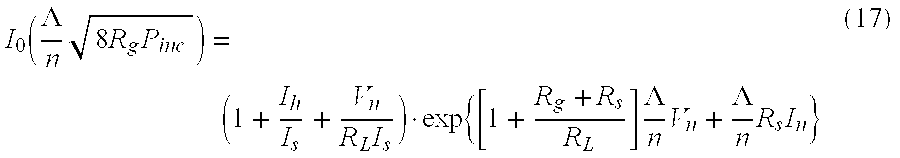
- I 0 is the zero-order modified Bessel function of the first kind, Rg is the source impedance, RL is the output load resistance, Io is bias circuit current for the circuit which is equal to 0 in power conversion applications.
- Equation 17 describes the relationship between incident power P inc on the detector Circuit and the output voltage V 0.
- In FIG. 14, which is a voltage doubler equivalent circuit, equation 17 can be applied. It will be seen that the output voltage of the voltage doubler is two times that of a detector circuit with one half the original load.
- Equation 17 is a good approximation of output voltage of a voltage doubler when C J is small or the operating frequency is low.
- For some applications the output voltage of a single voltage doubler may not be adequate to operate the remote device. One may employ multiple RF sources and add them together to achieve higher output voltage. If each independent source, with the voltage double circuit dedicated to it is seen as a battery with an open circuit output voltage V 0 and an internal resistance RL, the output voltage on a load with resistance RL will be

- when n of them are put together.
- As seen in
equation 18, the output voltage Vout is determined by the total of capital R0/RL and 1/n if V0 is fixed. When the load is close to or smaller than the internal resistance of the voltage doubler R0/RL becomes dominant when increasing n will not assist much in getting higher output voltage. - In summary, it is desirable to increase the I S and reduce the CJ of the Schottky Diode in order to increase the power conversion efficiency of a voltage doubler. Adding multiple voltage doublers in series is a way of getting higher output voltage subject to the gain decreasing when the load becomes heavy.
- With reference to FIG. 14, it will be noted that a further advantage of the present invention is that in connection with miniaturized electronics chips, the antenna may be provided within the rather small dimensions of the chip but have an effective antenna size greater than the physical antenna size. FIG. 14 shows such an antenna and FIG. 15 shows the antenna incorporated into an electronic microchip. Another advantage of the present system is that the system has the ability to incorporate an LC “tank” circuit in the antenna designs This is accomplished through the use in the antenna of inter-electrode capacitance and inductance to form the LC tank circuit.
- It will be appreciated, therefore, that the present invention provides an effective means for establishing a system wherein a base station cooperates with a remote station by exchanging data in both directions with the base station serving to provide transmitted energy which serves to energize the remote station to permit functioning thereof. As a result, there is no need to have a wired system connecting the remote station with a source of power or for it to carry a power storage unit. This permits low or no maintenance remote systems which may be implanted in individuals, used for other medical purposes, used in space, industry, security and a wide range of other uses. All of this is accomplished in a simple, efficient manner employing the apparatus and methods of the present invention.
- While for simplicity of disclosure primary attention herein has been directed toward a system employing RF power as the source of energy delivered to the remote station, and such is currently the preferred approach, it will be appreciated that alternate sources of power may be employed. A light beam, for example, with suitable means for receiving the light on the remote station and converting it to responsive electrical output, such as an appropriate DC voltage may be employed. The converter devices, such as CMOS or TTL, could provide voltages at desired levels and currents on the order of milliamps to power the device.
- Whereas particular embodiments of the invention have been described above for purposes of illustration, it will be appreciated by those skilled in the art that numerous variations of the details may be made without departing from the invention as described in the appended claims.
Claims (55)
1. Apparatus for remote interaction with an object of interest comprising
a remote station for obtaining information from said object of interest,
a base station for transmitting energy in space to and communicating with said remote station,
said remote station having conversion means for energizing said remote station responsive to receipt of said transmitted energy,
said remote station not having a power storage device for energizing
said remote station after termination of base station energy transmission to said remote station,
first antenna means operatively associated with said base station for transmitting signals to and receiving signals from said remote station,
second antenna means operatively associated with said remote station for receiving signals from said first antenna means and transmitting signals to said first antenna means, and
said second antenna means having at least one antenna having an effective antenna area greater than its physical area.
2. The apparatus of claim 1 including said remote station having an electronic chip on which said second antenna means is formed.
3. The apparatus of claim 2 including,
said second antenna means including a plurality of said second antennas.
4. The apparatus of claim 3 including
at least two of said second antennas structured to receive different frequencies.
5. The apparatus of claim 4 including
said first antenna means having a separate antenna for transmitting at each said frequency.
6. The apparatus of claim 2 including
said base antenna having means for transmitting said energy as RF power.
7. The apparatus of claim 6 including
said remote station having at least one voltage doubler.
8. The apparatus of claim 7 including
said remote station having at least two said voltage doublers in series.
9. The apparatus of claim 7 including
each said voltage doubler having at least one capacitor electrically interposed between said second antenna means and a diode.
10. The apparatus of claim 3 including,
said second antennas formed on said electronic chip.
11. The apparatus of claim 10 including
an LC link circuit formed in said second antenna means.
12. The apparatus of claim 2 including
said remote station is an RFID tag.
13. The apparatus of claim 1 including
said effective antenna area is at least 300 times the antenna's physical area.
14. The apparatus of claim 2 including said chip is a devise selected from the group consisting of a CMOS device and a MEMS device.
15. The apparatus of claim 2 including a power supply for energizing said base station.
16. The apparatus of claim 2 including
first controller means for controlling operation of said base station.
17. The apparatus of claim 16 including
said first controller means having microprocessor means.
18. The apparatus of claim 1 including
said remote station having means for converting said transmitted energy into DC power for energizing said remote station.
19. The apparatus of claim 18 including
said remote station having second controller means for processing information received from said base station and for transmitting information to said base station.
20. The apparatus of claim 19 including
said second controller means having means for receiving information from sensor means monitoring said object of interest.
21. The apparatus of claim 19 including
said object of interest being a patient.
22. The apparatus of claim 21 including
said sensor means having apparatus to monitor a body condition or body function of said patient.
23. The apparatus of claim 1 including
said remote station not having a power storage device physically secured thereto.
24. The apparatus of claim 1 including
said base station and said remote station having no wired connection therebetween.
25. The apparatus of claim 18 including
said base station transmitting both power signals and data signals to said remote station.
26. The apparatus of claim 2 including
said remote station having converter means for converting said RF power into DC or AC power.
27 The apparatus of claim 1 including
said remote station being sealed within a resinous plastic material.
28. A method for remote interaction with an object of interest comprising
providing a remote station and a base station operatively associated therewith,
transmitting energy in space from said base station to said remote station,
converting said energy received by said remote station into electrical power to energize said remote station,
effecting said energy received by said remote station into electrical power to energize said remote station,
effecting said remote interaction without requiring such remote station to have a power storage device secured thereto for energizing said remote station after termination of said base station transmission and said energy conversion,
employing antenna means for communication of said electrical power in space between said base station and said remote station,
said antenna means having first antenna means operatively associated with said base station and second antenna means operatively associated with said remote station, and
said second antenna means having at least one antenna having an effective antenna area greater than the physical area.
29. The method of claim 28 including
said remote station employing an electronic chip on which said second antenna means is formed.
30. The method of claim 29 including
employing a plurality of second antennas as said second antenna means.
31. The method of claim 31 including
at least two of said second antennas structured to receive different frequencies.
32. The method of claim 31 including
said first antenna means having antennas for transmitting at each said frequency.
33. The method of claim 29 including
transmitting said energy from said base station as RF power.
34. The method of claim 33 including
employing in said remote station at least one voltage doubler.
35. the method of claim 34 including
employing in said remote station at least two said voltage doublers in series.
36. The method of claim 34 including
providing in each said voltage doubler at least one capacitor electronically interposed between said second antenna means and a diode.
37. The method of claim 30 including
said second antennas formed on said electronic chip.
38. The method of claim 37 including
providing an LC link circuit in said second antenna.
39. The method of claim 29 including
employing as said remote station an RFID tag.
40. The method of claim 28 including
said effective antenna area is at least 300 times the antennas physical area.
41. The apparatus of claim 29 including
employing as said chip a device selected from type group consisting of a CMOS device and a MEMS device.
42. The method of claim 28 including
transmitting said energy as RF power.
43. The method of claim 28 including
energizing said base station by a power supply.
44. The method of claim 43 including
converting said transmittal energy to DC power at said remote station.
45. The method of claim 28 including
employing said method on an object of interest which is a patient.
46. The method of claim 28 including
sealing said remote station within a resinous plastic material.
47. The method of claim 45 including
employing said method to monitor a body condition or body function of said patient.
48. The method of claim 28 including
transmitting both power signals and data signals from said base station to said remote station.
49. The method of claim 48 including
transmitting data signals from said remote station to said base station.
50. The method of claim 36 including
employing a said remote station not having a power storage device.
51. The method of claim 50 including
employing first microprocessor means to control operation of said base station.
52. The method of claim 51 including
employing second microprocessor means to control said remote station.
53. The method of claim 45 including
positioning said remote station within 20 feet of said base station.
54. The method of claim 38 including
employing said method to confirm identification of an object of interest.
55. The method of claim 54 including
employing said method in a security system.
Priority Applications (1)
| Application Number | Priority Date | Filing Date | Title |
|---|---|---|---|
| US10/459,048 US20030199778A1 (en) | 1998-12-22 | 2003-06-11 | Apparatus for energizing a remote station and related method |
Applications Claiming Priority (3)
| Application Number | Priority Date | Filing Date | Title |
|---|---|---|---|
| US09/218,322 US6289237B1 (en) | 1998-12-22 | 1998-12-22 | Apparatus for energizing a remote station and related method |
| US09/951,032 US6615074B2 (en) | 1998-12-22 | 2001-09-10 | Apparatus for energizing a remote station and related method |
| US10/459,048 US20030199778A1 (en) | 1998-12-22 | 2003-06-11 | Apparatus for energizing a remote station and related method |
Related Parent Applications (1)
| Application Number | Title | Priority Date | Filing Date |
|---|---|---|---|
| US09/951,032 Division US6615074B2 (en) | 1998-12-22 | 2001-09-10 | Apparatus for energizing a remote station and related method |
Publications (1)
| Publication Number | Publication Date |
|---|---|
| US20030199778A1 true US20030199778A1 (en) | 2003-10-23 |
Family
ID=25491180
Family Applications (2)
| Application Number | Title | Priority Date | Filing Date |
|---|---|---|---|
| US09/951,032 Expired - Lifetime US6615074B2 (en) | 1998-12-22 | 2001-09-10 | Apparatus for energizing a remote station and related method |
| US10/459,048 Abandoned US20030199778A1 (en) | 1998-12-22 | 2003-06-11 | Apparatus for energizing a remote station and related method |
Family Applications Before (1)
| Application Number | Title | Priority Date | Filing Date |
|---|---|---|---|
| US09/951,032 Expired - Lifetime US6615074B2 (en) | 1998-12-22 | 2001-09-10 | Apparatus for energizing a remote station and related method |
Country Status (4)
| Country | Link |
|---|---|
| US (2) | US6615074B2 (en) |
| EP (1) | EP1455644A4 (en) |
| AU (1) | AU2002332698A1 (en) |
| WO (1) | WO2003023979A2 (en) |
Cited By (135)
| Publication number | Priority date | Publication date | Assignee | Title |
|---|---|---|---|---|
| WO2007019104A2 (en) * | 2005-08-04 | 2007-02-15 | Mhcmos, Llc | Harvesting ambient radio frequency electromagnetic energy for powering wireless electronic devices, sensors and sensor networks and applications thereof |
| US20070222542A1 (en) * | 2005-07-12 | 2007-09-27 | Joannopoulos John D | Wireless non-radiative energy transfer |
| US20080143192A1 (en) * | 2006-12-14 | 2008-06-19 | Sample Alanson P | Dynamic radio frequency power harvesting |
| US20080210762A1 (en) * | 2006-08-31 | 2008-09-04 | Semiconductor Energy Laboratory Co., Ltd. | Semiconductor device and power receiving device |
| WO2008118178A1 (en) * | 2007-03-27 | 2008-10-02 | Massachusetts Institute Of Technology | Wireless energy transfer |
| WO2008125072A1 (en) * | 2007-04-16 | 2008-10-23 | Siemens Aktiengesellschaft | Data transmission system having mobile radio participants, use of such a system and automation system |
| US20090072627A1 (en) * | 2007-03-02 | 2009-03-19 | Nigelpower, Llc | Maximizing Power Yield from Wireless Power Magnetic Resonators |
| WO2009038836A1 (en) * | 2007-09-21 | 2009-03-26 | Baxter International Inc. | Access disconnection detection system |
| WO2009151732A1 (en) * | 2008-06-11 | 2009-12-17 | International Business Machines Corporation | Intelligent wireless power charging system |
| US20100141042A1 (en) * | 2008-09-27 | 2010-06-10 | Kesler Morris P | Wireless energy transfer systems |
| US20100181844A1 (en) * | 2005-07-12 | 2010-07-22 | Aristeidis Karalis | High efficiency and power transfer in wireless power magnetic resonators |
| US20100318007A1 (en) * | 2009-06-10 | 2010-12-16 | O'brien Donald J | Electromechanical tactile stimulation devices and methods |
| US20110050166A1 (en) * | 2006-01-18 | 2011-03-03 | Qualcomm Incorporated | Method and system for powering an electronic device via a wireless link |
| US7913566B2 (en) | 2006-05-23 | 2011-03-29 | Rosemount Inc. | Industrial process device utilizing magnetic induction |
| US20110090058A1 (en) * | 2008-07-04 | 2011-04-21 | Murata Manufacturing Co., Ltd. | Radio ic device |
| US20110156872A1 (en) * | 2009-12-31 | 2011-06-30 | Alcatel-Lucent Usa Inc. | Smart rfid reader/router |
| US7977924B2 (en) | 2008-11-03 | 2011-07-12 | Rosemount Inc. | Industrial process power scavenging device and method of deriving process device power from an industrial process |
| US20110175461A1 (en) * | 2010-01-07 | 2011-07-21 | Audiovox Corporation | Method and apparatus for harvesting energy |
| US8076801B2 (en) | 2008-05-14 | 2011-12-13 | Massachusetts Institute Of Technology | Wireless energy transfer, including interference enhancement |
| US8115635B2 (en) | 2005-02-08 | 2012-02-14 | Abbott Diabetes Care Inc. | RF tag on test strips, test strip vials and boxes |
| US8145180B2 (en) | 2004-05-21 | 2012-03-27 | Rosemount Inc. | Power generation for process devices |
| US8250924B2 (en) | 2008-04-22 | 2012-08-28 | Rosemount Inc. | Industrial process device utilizing piezoelectric transducer |
| US8304935B2 (en) | 2008-09-27 | 2012-11-06 | Witricity Corporation | Wireless energy transfer using field shaping to reduce loss |
| US8324759B2 (en) | 2008-09-27 | 2012-12-04 | Witricity Corporation | Wireless energy transfer using magnetic materials to shape field and reduce loss |
| US8362651B2 (en) | 2008-10-01 | 2013-01-29 | Massachusetts Institute Of Technology | Efficient near-field wireless energy transfer using adiabatic system variations |
| US8373514B2 (en) | 2007-10-11 | 2013-02-12 | Qualcomm Incorporated | Wireless power transfer using magneto mechanical systems |
| US8378523B2 (en) | 2007-03-02 | 2013-02-19 | Qualcomm Incorporated | Transmitters and receivers for wireless energy transfer |
| US8400017B2 (en) | 2008-09-27 | 2013-03-19 | Witricity Corporation | Wireless energy transfer for computer peripheral applications |
| US8410636B2 (en) | 2008-09-27 | 2013-04-02 | Witricity Corporation | Low AC resistance conductor designs |
| US8441154B2 (en) | 2008-09-27 | 2013-05-14 | Witricity Corporation | Multi-resonator wireless energy transfer for exterior lighting |
| US8461722B2 (en) | 2008-09-27 | 2013-06-11 | Witricity Corporation | Wireless energy transfer using conducting surfaces to shape field and improve K |
| US8461721B2 (en) | 2008-09-27 | 2013-06-11 | Witricity Corporation | Wireless energy transfer using object positioning for low loss |
| US8461720B2 (en) | 2008-09-27 | 2013-06-11 | Witricity Corporation | Wireless energy transfer using conducting surfaces to shape fields and reduce loss |
| US8466583B2 (en) | 2008-09-27 | 2013-06-18 | Witricity Corporation | Tunable wireless energy transfer for outdoor lighting applications |
| US8471410B2 (en) | 2008-09-27 | 2013-06-25 | Witricity Corporation | Wireless energy transfer over distance using field shaping to improve the coupling factor |
| US8476788B2 (en) | 2008-09-27 | 2013-07-02 | Witricity Corporation | Wireless energy transfer with high-Q resonators using field shaping to improve K |
| US8482157B2 (en) | 2007-03-02 | 2013-07-09 | Qualcomm Incorporated | Increasing the Q factor of a resonator |
| US8482158B2 (en) | 2008-09-27 | 2013-07-09 | Witricity Corporation | Wireless energy transfer using variable size resonators and system monitoring |
| US20130178158A1 (en) * | 2007-08-02 | 2013-07-11 | University Of Pittsburgh - Of The Commonwealth System Of Higher Education | Wireless systems having multiple electronic devices and employing simplified fabrication and matching, and associated methods |
| US8487480B1 (en) | 2008-09-27 | 2013-07-16 | Witricity Corporation | Wireless energy transfer resonator kit |
| US8497601B2 (en) | 2008-09-27 | 2013-07-30 | Witricity Corporation | Wireless energy transfer converters |
| US8538560B2 (en) | 2004-04-29 | 2013-09-17 | Rosemount Inc. | Wireless power and communication unit for process field devices |
| US8552592B2 (en) | 2008-09-27 | 2013-10-08 | Witricity Corporation | Wireless energy transfer with feedback control for lighting applications |
| US8569914B2 (en) | 2008-09-27 | 2013-10-29 | Witricity Corporation | Wireless energy transfer using object positioning for improved k |
| US8587153B2 (en) | 2008-09-27 | 2013-11-19 | Witricity Corporation | Wireless energy transfer using high Q resonators for lighting applications |
| US8587155B2 (en) | 2008-09-27 | 2013-11-19 | Witricity Corporation | Wireless energy transfer using repeater resonators |
| US8598743B2 (en) | 2008-09-27 | 2013-12-03 | Witricity Corporation | Resonator arrays for wireless energy transfer |
| US8626087B2 (en) | 2009-06-16 | 2014-01-07 | Rosemount Inc. | Wire harness for field devices used in a hazardous locations |
| US8629576B2 (en) | 2008-03-28 | 2014-01-14 | Qualcomm Incorporated | Tuning and gain control in electro-magnetic power systems |
| US8629578B2 (en) | 2008-09-27 | 2014-01-14 | Witricity Corporation | Wireless energy transfer systems |
| US8643326B2 (en) | 2008-09-27 | 2014-02-04 | Witricity Corporation | Tunable wireless energy transfer systems |
| US8667452B2 (en) | 2011-11-04 | 2014-03-04 | Witricity Corporation | Wireless energy transfer modeling tool |
| US8669676B2 (en) | 2008-09-27 | 2014-03-11 | Witricity Corporation | Wireless energy transfer across variable distances using field shaping with magnetic materials to improve the coupling factor |
| US8686598B2 (en) | 2008-09-27 | 2014-04-01 | Witricity Corporation | Wireless energy transfer for supplying power and heat to a device |
| US8692412B2 (en) | 2008-09-27 | 2014-04-08 | Witricity Corporation | Temperature compensation in a wireless transfer system |
| US8694060B2 (en) | 2008-06-17 | 2014-04-08 | Rosemount Inc. | Form factor and electromagnetic interference protection for process device wireless adapters |
| US8692410B2 (en) | 2008-09-27 | 2014-04-08 | Witricity Corporation | Wireless energy transfer with frequency hopping |
| US8723366B2 (en) | 2008-09-27 | 2014-05-13 | Witricity Corporation | Wireless energy transfer resonator enclosures |
| US8729737B2 (en) | 2008-09-27 | 2014-05-20 | Witricity Corporation | Wireless energy transfer using repeater resonators |
| US8772973B2 (en) | 2008-09-27 | 2014-07-08 | Witricity Corporation | Integrated resonator-shield structures |
| US8787848B2 (en) | 2004-06-28 | 2014-07-22 | Rosemount Inc. | RF adapter for field device with low voltage intrinsic safety clamping |
| US8805530B2 (en) | 2007-06-01 | 2014-08-12 | Witricity Corporation | Power generation for implantable devices |
| US8847548B2 (en) | 2008-09-27 | 2014-09-30 | Witricity Corporation | Wireless energy transfer for implantable devices |
| US8847571B2 (en) | 2008-06-17 | 2014-09-30 | Rosemount Inc. | RF adapter for field device with variable voltage drop |
| US8901778B2 (en) | 2008-09-27 | 2014-12-02 | Witricity Corporation | Wireless energy transfer with variable size resonators for implanted medical devices |
| US8901779B2 (en) | 2008-09-27 | 2014-12-02 | Witricity Corporation | Wireless energy transfer with resonator arrays for medical applications |
| US8907531B2 (en) | 2008-09-27 | 2014-12-09 | Witricity Corporation | Wireless energy transfer with variable size resonators for medical applications |
| US8912687B2 (en) | 2008-09-27 | 2014-12-16 | Witricity Corporation | Secure wireless energy transfer for vehicle applications |
| US8922066B2 (en) | 2008-09-27 | 2014-12-30 | Witricity Corporation | Wireless energy transfer with multi resonator arrays for vehicle applications |
| US8928276B2 (en) | 2008-09-27 | 2015-01-06 | Witricity Corporation | Integrated repeaters for cell phone applications |
| US8929948B2 (en) | 2008-06-17 | 2015-01-06 | Rosemount Inc. | Wireless communication adapter for field devices |
| US8933594B2 (en) | 2008-09-27 | 2015-01-13 | Witricity Corporation | Wireless energy transfer for vehicles |
| US8937408B2 (en) | 2008-09-27 | 2015-01-20 | Witricity Corporation | Wireless energy transfer for medical applications |
| US8946938B2 (en) | 2008-09-27 | 2015-02-03 | Witricity Corporation | Safety systems for wireless energy transfer in vehicle applications |
| US8947186B2 (en) | 2008-09-27 | 2015-02-03 | Witricity Corporation | Wireless energy transfer resonator thermal management |
| US8957549B2 (en) | 2008-09-27 | 2015-02-17 | Witricity Corporation | Tunable wireless energy transfer for in-vehicle applications |
| US8963488B2 (en) | 2008-09-27 | 2015-02-24 | Witricity Corporation | Position insensitive wireless charging |
| US9035499B2 (en) | 2008-09-27 | 2015-05-19 | Witricity Corporation | Wireless energy transfer for photovoltaic panels |
| US9065423B2 (en) | 2008-09-27 | 2015-06-23 | Witricity Corporation | Wireless energy distribution system |
| US9093853B2 (en) | 2008-09-27 | 2015-07-28 | Witricity Corporation | Flexible resonator attachment |
| US9106203B2 (en) | 2008-09-27 | 2015-08-11 | Witricity Corporation | Secure wireless energy transfer in medical applications |
| US9105959B2 (en) | 2008-09-27 | 2015-08-11 | Witricity Corporation | Resonator enclosure |
| US9124120B2 (en) | 2007-06-11 | 2015-09-01 | Qualcomm Incorporated | Wireless power system and proximity effects |
| US9130602B2 (en) | 2006-01-18 | 2015-09-08 | Qualcomm Incorporated | Method and apparatus for delivering energy to an electrical or electronic device via a wireless link |
| US9160203B2 (en) | 2008-09-27 | 2015-10-13 | Witricity Corporation | Wireless powered television |
| US9184595B2 (en) | 2008-09-27 | 2015-11-10 | Witricity Corporation | Wireless energy transfer in lossy environments |
| US9246336B2 (en) | 2008-09-27 | 2016-01-26 | Witricity Corporation | Resonator optimizations for wireless energy transfer |
| US9287607B2 (en) | 2012-07-31 | 2016-03-15 | Witricity Corporation | Resonator fine tuning |
| WO2016048859A1 (en) * | 2014-09-23 | 2016-03-31 | University Of Pittsburgh-Of The Commonwealth System Of Higher Education | Passively powered image capture and transmission system |
| US9306635B2 (en) | 2012-01-26 | 2016-04-05 | Witricity Corporation | Wireless energy transfer with reduced fields |
| US9310794B2 (en) | 2011-10-27 | 2016-04-12 | Rosemount Inc. | Power supply for industrial process field device |
| US9318257B2 (en) | 2011-10-18 | 2016-04-19 | Witricity Corporation | Wireless energy transfer for packaging |
| US9318922B2 (en) | 2008-09-27 | 2016-04-19 | Witricity Corporation | Mechanically removable wireless power vehicle seat assembly |
| US9343922B2 (en) | 2012-06-27 | 2016-05-17 | Witricity Corporation | Wireless energy transfer for rechargeable batteries |
| JP2016119836A (en) * | 2014-12-23 | 2016-06-30 | パロ アルト リサーチ センター インコーポレイテッド | Rectifier circuit for performing multi-band high frequency (rf) energy harvesting |
| US9384885B2 (en) | 2011-08-04 | 2016-07-05 | Witricity Corporation | Tunable wireless power architectures |
| US9396867B2 (en) | 2008-09-27 | 2016-07-19 | Witricity Corporation | Integrated resonator-shield structures |
| US9404954B2 (en) | 2012-10-19 | 2016-08-02 | Witricity Corporation | Foreign object detection in wireless energy transfer systems |
| US9421388B2 (en) | 2007-06-01 | 2016-08-23 | Witricity Corporation | Power generation for implantable devices |
| US9442172B2 (en) | 2011-09-09 | 2016-09-13 | Witricity Corporation | Foreign object detection in wireless energy transfer systems |
| US9449757B2 (en) | 2012-11-16 | 2016-09-20 | Witricity Corporation | Systems and methods for wireless power system with improved performance and/or ease of use |
| US9515494B2 (en) | 2008-09-27 | 2016-12-06 | Witricity Corporation | Wireless power system including impedance matching network |
| US9544683B2 (en) | 2008-09-27 | 2017-01-10 | Witricity Corporation | Wirelessly powered audio devices |
| US9595378B2 (en) | 2012-09-19 | 2017-03-14 | Witricity Corporation | Resonator enclosure |
| US9602168B2 (en) | 2010-08-31 | 2017-03-21 | Witricity Corporation | Communication in wireless energy transfer systems |
| US9601266B2 (en) | 2008-09-27 | 2017-03-21 | Witricity Corporation | Multiple connected resonators with a single electronic circuit |
| US9601267B2 (en) | 2013-07-03 | 2017-03-21 | Qualcomm Incorporated | Wireless power transmitter with a plurality of magnetic oscillators |
| US9601270B2 (en) | 2008-09-27 | 2017-03-21 | Witricity Corporation | Low AC resistance conductor designs |
| US9674976B2 (en) | 2009-06-16 | 2017-06-06 | Rosemount Inc. | Wireless process communication adapter with improved encapsulation |
| US9744858B2 (en) | 2008-09-27 | 2017-08-29 | Witricity Corporation | System for wireless energy distribution in a vehicle |
| US9774086B2 (en) | 2007-03-02 | 2017-09-26 | Qualcomm Incorporated | Wireless power apparatus and methods |
| US9780573B2 (en) | 2014-02-03 | 2017-10-03 | Witricity Corporation | Wirelessly charged battery system |
| US9837860B2 (en) | 2014-05-05 | 2017-12-05 | Witricity Corporation | Wireless power transmission systems for elevators |
| US9843217B2 (en) | 2015-01-05 | 2017-12-12 | Witricity Corporation | Wireless energy transfer for wearables |
| US9842687B2 (en) | 2014-04-17 | 2017-12-12 | Witricity Corporation | Wireless power transfer systems with shaped magnetic components |
| US9842688B2 (en) | 2014-07-08 | 2017-12-12 | Witricity Corporation | Resonator balancing in wireless power transfer systems |
| US9857821B2 (en) | 2013-08-14 | 2018-01-02 | Witricity Corporation | Wireless power transfer frequency adjustment |
| US9892849B2 (en) | 2014-04-17 | 2018-02-13 | Witricity Corporation | Wireless power transfer systems with shield openings |
| US9929721B2 (en) | 2015-10-14 | 2018-03-27 | Witricity Corporation | Phase and amplitude detection in wireless energy transfer systems |
| US9948145B2 (en) | 2011-07-08 | 2018-04-17 | Witricity Corporation | Wireless power transfer for a seat-vest-helmet system |
| US9954375B2 (en) | 2014-06-20 | 2018-04-24 | Witricity Corporation | Wireless power transfer systems for surfaces |
| US9952266B2 (en) | 2014-02-14 | 2018-04-24 | Witricity Corporation | Object detection for wireless energy transfer systems |
| US10018744B2 (en) | 2014-05-07 | 2018-07-10 | Witricity Corporation | Foreign object detection in wireless energy transfer systems |
| US10063110B2 (en) | 2015-10-19 | 2018-08-28 | Witricity Corporation | Foreign object detection in wireless energy transfer systems |
| US10063104B2 (en) | 2016-02-08 | 2018-08-28 | Witricity Corporation | PWM capacitor control |
| US10075019B2 (en) | 2015-11-20 | 2018-09-11 | Witricity Corporation | Voltage source isolation in wireless power transfer systems |
| US10141788B2 (en) | 2015-10-22 | 2018-11-27 | Witricity Corporation | Dynamic tuning in wireless energy transfer systems |
| US10248899B2 (en) | 2015-10-06 | 2019-04-02 | Witricity Corporation | RFID tag and transponder detection in wireless energy transfer systems |
| US10263473B2 (en) | 2016-02-02 | 2019-04-16 | Witricity Corporation | Controlling wireless power transfer systems |
| US10424976B2 (en) | 2011-09-12 | 2019-09-24 | Witricity Corporation | Reconfigurable control architectures and algorithms for electric vehicle wireless energy transfer systems |
| US10574091B2 (en) | 2014-07-08 | 2020-02-25 | Witricity Corporation | Enclosures for high power wireless power transfer systems |
| US10761524B2 (en) | 2010-08-12 | 2020-09-01 | Rosemount Inc. | Wireless adapter with process diagnostics |
| US11031818B2 (en) | 2017-06-29 | 2021-06-08 | Witricity Corporation | Protection and control of wireless power systems |
| EP3782261A4 (en) * | 2018-04-16 | 2021-12-29 | Nikola Labs | Systems and methods for machine condition monitoring |
| US11883176B2 (en) | 2020-05-29 | 2024-01-30 | The Research Foundation For The State University Of New York | Low-power wearable smart ECG patch with on-board analytics |
Families Citing this family (403)
| Publication number | Priority date | Publication date | Assignee | Title |
|---|---|---|---|---|
| US6615074B2 (en) * | 1998-12-22 | 2003-09-02 | University Of Pittsburgh Of The Commonwealth System Of Higher Education | Apparatus for energizing a remote station and related method |
| US6867696B2 (en) * | 2001-07-02 | 2005-03-15 | Fraba Sicherheitssysteme Gmbh | Wireless transmission of signals and statuses from mobile devices to stationary or mobile devices |
| US6697013B2 (en) * | 2001-12-06 | 2004-02-24 | Atheros Communications, Inc. | Radar detection and dynamic frequency selection for wireless local area networks |
| JP4347216B2 (en) * | 2002-04-22 | 2009-10-21 | マルシオ マルク アブリュー | Biological parameter measuring device |
| US6856291B2 (en) * | 2002-08-15 | 2005-02-15 | University Of Pittsburgh- Of The Commonwealth System Of Higher Education | Energy harvesting circuits and associated methods |
| US7373133B2 (en) * | 2002-09-18 | 2008-05-13 | University Of Pittsburgh - Of The Commonwealth System Of Higher Education | Recharging method and apparatus |
| US7440780B2 (en) * | 2002-09-18 | 2008-10-21 | University Of Pittsburgh - Of The Commonwealth System Of Higher Education | Recharging method and apparatus |
| US6914528B2 (en) * | 2002-10-02 | 2005-07-05 | Battelle Memorial Institute | Wireless communication systems, radio frequency identification devices, methods of enhancing a communications range of a radio frequency identification device, and wireless communication methods |
| US7727181B2 (en) * | 2002-10-09 | 2010-06-01 | Abbott Diabetes Care Inc. | Fluid delivery device with autocalibration |
| DE60336834D1 (en) | 2002-10-09 | 2011-06-01 | Abbott Diabetes Care Inc | FUEL FEEDING DEVICE, SYSTEM AND METHOD |
| US7993108B2 (en) | 2002-10-09 | 2011-08-09 | Abbott Diabetes Care Inc. | Variable volume, shape memory actuated insulin dispensing pump |
| US7221323B2 (en) * | 2003-12-12 | 2007-05-22 | Hans Gregory Schantz | Tag-along microsensor device and method |
| US7606193B2 (en) * | 2003-01-30 | 2009-10-20 | Atheros Communications, Inc. | Methods for implementing a dynamic frequency selection (DFS) feature for WLAN devices |
| JP2004326671A (en) * | 2003-04-28 | 2004-11-18 | National Institute Of Advanced Industrial & Technology | Remote calibration system for metering instrument and remote calibration method for metering instrument |
| US7679407B2 (en) | 2003-04-28 | 2010-03-16 | Abbott Diabetes Care Inc. | Method and apparatus for providing peak detection circuitry for data communication systems |
| US7403803B2 (en) * | 2003-05-20 | 2008-07-22 | University Of Pittsburgh - Of The Commonwealth System Of Higher Education | Recharging method and associated apparatus |
| EP1629446A4 (en) * | 2003-06-02 | 2007-07-25 | Univ Pittsburgh | Antenna on a wireless untethered device such as a chip or printed circuit board for harvesting energy from space |
| US8071028B2 (en) | 2003-06-12 | 2011-12-06 | Abbott Diabetes Care Inc. | Method and apparatus for providing power management in data communication systems |
| CN1813271B (en) * | 2003-06-25 | 2010-12-01 | Nxp股份有限公司 | Method and arrangements for increasing the security of transponder systems, particularly for access to automobiles |
| US7084605B2 (en) * | 2003-10-29 | 2006-08-01 | University Of Pittsburgh | Energy harvesting circuit |
| US7956742B2 (en) | 2003-10-30 | 2011-06-07 | Motedata Inc. | Method and system for storing, retrieving, and managing data for tags |
| US7388488B2 (en) * | 2003-10-30 | 2008-06-17 | Peter Lupoli | Method and system for storing, retrieving, and managing data for tags |
| US7416530B2 (en) * | 2003-11-04 | 2008-08-26 | L & P 100 Limited | Medical devices |
| US20050165317A1 (en) * | 2003-11-04 | 2005-07-28 | Turner Nicholas M. | Medical devices |
| US7010385B1 (en) * | 2003-11-21 | 2006-03-07 | Oberg Industries | Method of monitoring operation of an automated tool and associated apparatus |
| US20050182459A1 (en) * | 2003-12-30 | 2005-08-18 | John Constance M. | Apparatus for harvesting and storing energy on a chip |
| FR2865560B1 (en) * | 2004-01-23 | 2006-05-19 | Neopost Ind | METHOD FOR DETERMINING THE STATE OF PRESERVATION OF A PRODUCT |
| JP2007519484A (en) * | 2004-01-27 | 2007-07-19 | アルティベラ・リミテッド・ライアビリティ・カンパニー | Diagnostic radio frequency identification sensor and its application |
| US20070173732A1 (en) * | 2004-01-29 | 2007-07-26 | Elvir Causevic | Method and apparatus for wireless brain interface |
| US7461560B2 (en) * | 2005-03-28 | 2008-12-09 | Microstrain, Inc. | Strain gauge with moisture barrier and self-testing circuit |
| EP1742567A1 (en) * | 2004-04-28 | 2007-01-17 | Université René Descartes - Paris 5 | Skin potential measurement method and system |
| US7240833B2 (en) * | 2004-05-20 | 2007-07-10 | Cardiac Pacemakers, Inc. | System and method of managing information for an implantable medical device |
| US7794499B2 (en) * | 2004-06-08 | 2010-09-14 | Theken Disc, L.L.C. | Prosthetic intervertebral spinal disc with integral microprocessor |
| US20060009817A1 (en) * | 2004-07-12 | 2006-01-12 | Radi Medical Systems Ab | Wireless communication of physiological variables |
| WO2006029007A2 (en) * | 2004-09-02 | 2006-03-16 | E-Soc | Device for brain stimulation using rf energy harvesting |
| US20060061483A1 (en) * | 2004-09-17 | 2006-03-23 | Smith Timothy D | Monitoring and security system and method |
| US20060161216A1 (en) * | 2004-10-18 | 2006-07-20 | John Constance M | Device for neuromuscular peripheral body stimulation and electrical stimulation (ES) for wound healing using RF energy harvesting |
| KR100582730B1 (en) * | 2004-10-26 | 2006-05-23 | 삼성전자주식회사 | apparatus and method for transmitting data in facsimile |
| WO2006049606A1 (en) * | 2004-10-28 | 2006-05-11 | University Of Pittsburgh Of The Commonwealth System Of Higher Education | Active automatic tuning for a recharging circuit |
| WO2006048664A2 (en) * | 2004-11-04 | 2006-05-11 | L & P 100 Limited | Medical devices |
| US7656569B2 (en) | 2004-12-03 | 2010-02-02 | Searete Llc | Vision modification with reflected image |
| US8244342B2 (en) | 2004-12-03 | 2012-08-14 | The Invention Science Fund I, Llc | Method and system for adaptive vision modification |
| US8104892B2 (en) | 2004-12-03 | 2012-01-31 | The Invention Science Fund I, Llc | Vision modification with reflected image |
| US7931373B2 (en) | 2004-12-03 | 2011-04-26 | The Invention Science Fund I, Llc | Vision modification with reflected image |
| US9155483B2 (en) | 2004-12-03 | 2015-10-13 | The Invention Science Fund I, Llc | Vision modification with reflected image |
| US7486988B2 (en) | 2004-12-03 | 2009-02-03 | Searete Llc | Method and system for adaptive vision modification |
| WO2006069144A2 (en) * | 2004-12-21 | 2006-06-29 | University Of Pittsburgh - Of The Commonwealth System Of Higher Education | Deep brain stimulation apparatus, and associated methods |
| US20070149162A1 (en) * | 2005-02-24 | 2007-06-28 | Powercast, Llc | Pulse transmission method |
| CA2601441A1 (en) | 2005-03-21 | 2006-09-28 | Abbott Diabetes Care Inc. | Method and system for providing integrated medication infusion and analyte monitoring system |
| US7722920B2 (en) * | 2005-05-13 | 2010-05-25 | University Of Pittsburgh-Of The Commonwealth System Of Higher Education | Method of making an electronic device using an electrically conductive polymer, and associated products |
| US7768408B2 (en) | 2005-05-17 | 2010-08-03 | Abbott Diabetes Care Inc. | Method and system for providing data management in data monitoring system |
| US7844232B2 (en) * | 2005-05-25 | 2010-11-30 | Research In Motion Limited | Joint space-time optimum filters (JSTOF) with at least one antenna, at least one channel, and joint filter weight and CIR estimation |
| US7620437B2 (en) | 2005-06-03 | 2009-11-17 | Abbott Diabetes Care Inc. | Method and apparatus for providing rechargeable power in data monitoring and management systems |
| WO2006133380A2 (en) * | 2005-06-07 | 2006-12-14 | University Of Pittsburgh - Of The Commonwealth System Of Higher Education | Manufacturing of electronic devices using conductive polymer |
| US20060281435A1 (en) * | 2005-06-08 | 2006-12-14 | Firefly Power Technologies, Inc. | Powering devices using RF energy harvesting |
| JP2008543513A (en) | 2005-06-27 | 2008-12-04 | センス エー/エス | Blood pressure determination method and apparatus |
| AU2006269336A1 (en) * | 2005-07-08 | 2007-01-18 | Powercast Corporation | Power transmission system, apparatus and method with communication |
| GB0516470D0 (en) * | 2005-08-10 | 2005-09-14 | Cambridge Neurotechnology Ltd | Information transmission method and apparatus |
| US7756561B2 (en) | 2005-09-30 | 2010-07-13 | Abbott Diabetes Care Inc. | Method and apparatus for providing rechargeable power in data monitoring and management systems |
| US7733224B2 (en) | 2006-06-30 | 2010-06-08 | Bao Tran | Mesh network personal emergency response appliance |
| ZA200803885B (en) * | 2005-10-24 | 2009-08-26 | Powercast Corp | Method and apparatus for high efficiency rectification for various loads |
| US7583190B2 (en) | 2005-10-31 | 2009-09-01 | Abbott Diabetes Care Inc. | Method and apparatus for providing data communication in data monitoring and management systems |
| US9067047B2 (en) | 2005-11-09 | 2015-06-30 | The Invention Science Fund I, Llc | Injectable controlled release fluid delivery system |
| US7686768B2 (en) | 2005-11-23 | 2010-03-30 | Vital Sensors Holding Company, Inc. | Implantable pressure monitor |
| US7682313B2 (en) * | 2005-11-23 | 2010-03-23 | Vital Sensors Holding Company, Inc. | Implantable pressure monitor |
| US20070142872A1 (en) * | 2005-12-21 | 2007-06-21 | Mickle Marlin H | Deep brain stimulation apparatus, and associated methods |
| US7692411B2 (en) * | 2006-01-05 | 2010-04-06 | Tpl, Inc. | System for energy harvesting and/or generation, storage, and delivery |
| US20070173214A1 (en) * | 2006-01-05 | 2007-07-26 | University Of Pittsburgh-Of The Commonwealth System Of Higher Education | Wireless autonomous device system |
| WO2007079491A2 (en) | 2006-01-05 | 2007-07-12 | University Of Pittsburgh-Of The Commonwealth System Of Higher Education | Multiple antenna energy harvesting |
| US8344966B2 (en) | 2006-01-31 | 2013-01-01 | Abbott Diabetes Care Inc. | Method and system for providing a fault tolerant display unit in an electronic device |
| US8246563B2 (en) * | 2006-02-02 | 2012-08-21 | Cardiac Pacemakers, Inc. | Cardiac rhythm management device and sensor-suite for the optimal control of ultrafiltration and renal replacement therapies |
| US20080140057A1 (en) | 2006-03-09 | 2008-06-12 | Searete Llc, A Limited Liability Corporation Of State Of The Delaware | Injectable controlled release fluid delivery system |
| US20090105782A1 (en) * | 2006-03-15 | 2009-04-23 | University Of Pittsburgh-Of The Commonwealth System Of Higher Education | Vagus nerve stimulation apparatus, and associated methods |
| JP2009530964A (en) * | 2006-03-22 | 2009-08-27 | パワーキャスト コーポレイション | Method and apparatus for implementation of a wireless power supply |
| DE102006020866A1 (en) * | 2006-05-04 | 2007-11-15 | Siemens Ag | Analyte e.g. DNA, analyzer for use in biosensor, has transponder e.g. passive transponder, provided for wireless information exchange with selection device, which is electrically connected with oscillating crystal |
| WO2007131093A2 (en) | 2006-05-05 | 2007-11-15 | University Of Pittsburgh-Of The Commonwealth System Of Higher Education | Wireless autonomous device data transmission |
| US8684922B2 (en) | 2006-05-12 | 2014-04-01 | Bao Tran | Health monitoring system |
| US8323189B2 (en) | 2006-05-12 | 2012-12-04 | Bao Tran | Health monitoring appliance |
| US9060683B2 (en) | 2006-05-12 | 2015-06-23 | Bao Tran | Mobile wireless appliance |
| US8500636B2 (en) | 2006-05-12 | 2013-08-06 | Bao Tran | Health monitoring appliance |
| US7539532B2 (en) | 2006-05-12 | 2009-05-26 | Bao Tran | Cuffless blood pressure monitoring appliance |
| US7558622B2 (en) | 2006-05-24 | 2009-07-07 | Bao Tran | Mesh network stroke monitoring appliance |
| US8968195B2 (en) | 2006-05-12 | 2015-03-03 | Bao Tran | Health monitoring appliance |
| US7539533B2 (en) | 2006-05-16 | 2009-05-26 | Bao Tran | Mesh network monitoring appliance |
| US8684900B2 (en) | 2006-05-16 | 2014-04-01 | Bao Tran | Health monitoring appliance |
| US20080131133A1 (en) * | 2006-05-17 | 2008-06-05 | Blunt Shannon D | Low sinr backscatter communications system and method |
| US9820658B2 (en) | 2006-06-30 | 2017-11-21 | Bao Q. Tran | Systems and methods for providing interoperability among healthcare devices |
| US8344888B2 (en) * | 2006-08-31 | 2013-01-01 | Semiconductor Energy Laboratory Co., Ltd. | Semiconductor device |
| KR100839961B1 (en) * | 2006-08-31 | 2008-06-19 | 광주과학기술원 | Measuring Sensor for Urinary Bladder Volume, and Urinary Bladder Management System Using Device, and Method Therefor |
| US7864507B2 (en) | 2006-09-06 | 2011-01-04 | Tpl, Inc. | Capacitors with low equivalent series resistance |
| US8579853B2 (en) | 2006-10-31 | 2013-11-12 | Abbott Diabetes Care Inc. | Infusion devices and methods |
| US7973608B2 (en) | 2006-11-30 | 2011-07-05 | Semiconductor Energy Laboratory Co., Ltd. | Phase locked loop, semiconductor device, and wireless tag |
| US8873585B2 (en) | 2006-12-19 | 2014-10-28 | Corning Optical Communications Wireless Ltd | Distributed antenna system for MIMO technologies |
| WO2008085503A2 (en) * | 2007-01-05 | 2008-07-17 | Powercast Corporation | Powering cell phones and similar devices using rf energy harvesting |
| WO2008088984A2 (en) | 2007-01-11 | 2008-07-24 | University Of Pittsburgh - Of The Commonwealth System Of Higher Education | Transponder networks and transponder systems employing a touch probe reader device |
| WO2008103375A2 (en) * | 2007-02-19 | 2008-08-28 | Mobileaccess Networks Ltd. | Method and system for improving uplink performance |
| US20080290822A1 (en) * | 2007-05-23 | 2008-11-27 | Greene Charles E | Item and method for wirelessly powering the item |
| US8750971B2 (en) | 2007-05-24 | 2014-06-10 | Bao Tran | Wireless stroke monitoring |
| GB2462779B (en) | 2007-05-25 | 2012-03-07 | Searete Llc | Injectable controlled release fluid delivery system |
| DE602008003953D1 (en) * | 2007-05-31 | 2011-01-27 | Semiconductor Energy Lab | Power supply for RFID transponders |
| US8159364B2 (en) | 2007-06-14 | 2012-04-17 | Omnilectric, Inc. | Wireless power transmission system |
| US11264841B2 (en) | 2007-06-14 | 2022-03-01 | Ossia Inc. | Wireless power transmission system |
| US8446248B2 (en) * | 2007-06-14 | 2013-05-21 | Omnilectric, Inc. | Wireless power transmission system |
| DE102007028133A1 (en) * | 2007-06-19 | 2008-12-24 | Fresenius Medical Care Deutschland Gmbh | Medical blood treatment device for extracorporeal blood treatment |
| US20100054746A1 (en) | 2007-07-24 | 2010-03-04 | Eric Raymond Logan | Multi-port accumulator for radio-over-fiber (RoF) wireless picocellular systems |
| US8175459B2 (en) | 2007-10-12 | 2012-05-08 | Corning Cable Systems Llc | Hybrid wireless/wired RoF transponder and hybrid RoF communication system using same |
| EP2203799A4 (en) | 2007-10-22 | 2017-05-17 | Mobileaccess Networks Ltd. | Communication system using low bandwidth wires |
| US20090117872A1 (en) * | 2007-11-05 | 2009-05-07 | Jorgenson Joel A | Passively powered element with multiple energy harvesting and communication channels |
| US8175649B2 (en) | 2008-06-20 | 2012-05-08 | Corning Mobileaccess Ltd | Method and system for real time control of an active antenna over a distributed antenna system |
| WO2009081376A2 (en) | 2007-12-20 | 2009-07-02 | Mobileaccess Networks Ltd. | Extending outdoor location based services and applications into enclosed areas |
| TWI364895B (en) * | 2008-06-09 | 2012-05-21 | Univ Nat Taipei Technology | Wireless power transmitting apparatus |
| WO2010057495A2 (en) * | 2008-11-18 | 2010-05-27 | Sense A/S | Methods, apparatus and sensor for measurement of cardiovascular quantities |
| US8442644B2 (en) | 2008-11-18 | 2013-05-14 | Greatbatch Ltd. | Satellite therapy delivery system for brain neuromodulation |
| EP2186541B1 (en) | 2008-11-18 | 2012-06-27 | Greatbatch Ltd. | Satellite therapy delivery system for brain neuromodulation |
| US8098143B2 (en) | 2008-12-10 | 2012-01-17 | Lockheed Martin Corporation | Power aware techniques for energy harvesting remote sensor system |
| DE102008062319B4 (en) * | 2008-12-16 | 2012-05-31 | Dräger Medical GmbH | Hose nozzle for a ventilator |
| US8560082B2 (en) | 2009-01-30 | 2013-10-15 | Abbott Diabetes Care Inc. | Computerized determination of insulin pump therapy parameters using real time and retrospective data processing |
| US9673904B2 (en) | 2009-02-03 | 2017-06-06 | Corning Optical Communications LLC | Optical fiber-based distributed antenna systems, components, and related methods for calibration thereof |
| JP5480916B2 (en) | 2009-02-03 | 2014-04-23 | コーニング ケーブル システムズ リミテッド ライアビリティ カンパニー | Fiber optic based distributed antenna system, components, and related methods for calibration thereof |
| JP2012517190A (en) | 2009-02-03 | 2012-07-26 | コーニング ケーブル システムズ リミテッド ライアビリティ カンパニー | Fiber optic based distributed antenna system, components and related methods for monitoring and configuration thereof |
| JP5649588B2 (en) | 2009-02-08 | 2015-01-07 | コーニング モバイルアクセス エルティディ. | Communication system using a cable for carrying an Ethernet signal |
| US20100253156A1 (en) * | 2009-04-07 | 2010-10-07 | Jeffrey Iott | Sensor device powered through rf harvesting |
| WO2010129375A1 (en) | 2009-04-28 | 2010-11-11 | Abbott Diabetes Care Inc. | Closed loop blood glucose control algorithm analysis |
| EP2456351B1 (en) | 2009-07-23 | 2016-10-12 | Abbott Diabetes Care, Inc. | Real time management of data relating to physiological control of glucose levels |
| US9590733B2 (en) | 2009-07-24 | 2017-03-07 | Corning Optical Communications LLC | Location tracking using fiber optic array cables and related systems and methods |
| US8548330B2 (en) | 2009-07-31 | 2013-10-01 | Corning Cable Systems Llc | Sectorization in distributed antenna systems, and related components and methods |
| US8280259B2 (en) | 2009-11-13 | 2012-10-02 | Corning Cable Systems Llc | Radio-over-fiber (RoF) system for protocol-independent wired and/or wireless communication |
| TW201126383A (en) * | 2010-01-20 | 2011-08-01 | Kye Systems Corp | Radio-frequency mouse |
| US8275265B2 (en) | 2010-02-15 | 2012-09-25 | Corning Cable Systems Llc | Dynamic cell bonding (DCB) for radio-over-fiber (RoF)-based networks and communication systems and related methods |
| EP2553839A1 (en) | 2010-03-31 | 2013-02-06 | Corning Cable Systems LLC | Localization services in optical fiber-based distributed communications components and systems, and related methods |
| US9525488B2 (en) | 2010-05-02 | 2016-12-20 | Corning Optical Communications LLC | Digital data services and/or power distribution in optical fiber-based distributed communications systems providing digital data and radio frequency (RF) communications services, and related components and methods |
| US20110268446A1 (en) | 2010-05-02 | 2011-11-03 | Cune William P | Providing digital data services in optical fiber-based distributed radio frequency (rf) communications systems, and related components and methods |
| US8330298B2 (en) | 2010-06-17 | 2012-12-11 | Scarf Technologies Llc | Generating DC electric power from ambient electromagnetic radiation |
| US8570914B2 (en) | 2010-08-09 | 2013-10-29 | Corning Cable Systems Llc | Apparatuses, systems, and methods for determining location of a mobile device(s) in a distributed antenna system(s) |
| GB201013590D0 (en) * | 2010-08-13 | 2010-09-29 | Chintala Sandeep K | Wireless power |
| WO2012024247A1 (en) | 2010-08-16 | 2012-02-23 | Corning Cable Systems Llc | Remote antenna clusters and related systems, components, and methods supporting digital data signal propagation between remote antenna units |
| US9160449B2 (en) | 2010-10-13 | 2015-10-13 | Ccs Technology, Inc. | Local power management for remote antenna units in distributed antenna systems |
| US9252874B2 (en) | 2010-10-13 | 2016-02-02 | Ccs Technology, Inc | Power management for remote antenna units in distributed antenna systems |
| DE102010049265B4 (en) * | 2010-10-25 | 2013-05-16 | Phoenix Contact Gmbh & Co. Kg | Method and device for power recovery |
| US11296504B2 (en) | 2010-11-24 | 2022-04-05 | Corning Optical Communications LLC | Power distribution module(s) capable of hot connection and/or disconnection for wireless communication systems, and related power units, components, and methods |
| WO2012071367A1 (en) | 2010-11-24 | 2012-05-31 | Corning Cable Systems Llc | Power distribution module(s) capable of hot connection and/or disconnection for distributed antenna systems, and related power units, components, and methods |
| US8816536B2 (en) | 2010-11-24 | 2014-08-26 | Georgia-Pacific Consumer Products Lp | Apparatus and method for wirelessly powered dispensing |
| KR20120071110A (en) * | 2010-12-22 | 2012-07-02 | 한국전자통신연구원 | Base station, terminal, and operating method thereof |
| CN203504582U (en) | 2011-02-21 | 2014-03-26 | 康宁光缆系统有限责任公司 | Distributed antenna system and power supply apparatus for distributing electric power thereof |
| EP2702710A4 (en) | 2011-04-29 | 2014-10-29 | Corning Cable Sys Llc | Determining propagation delay of communications in distributed antenna systems, and related components, systems and methods |
| CN103609146B (en) | 2011-04-29 | 2017-05-31 | 康宁光缆系统有限责任公司 | For increasing the radio frequency in distributing antenna system(RF)The system of power, method and apparatus |
| US9030053B2 (en) | 2011-05-19 | 2015-05-12 | Choon Sae Lee | Device for collecting energy wirelessly |
| US8933589B2 (en) | 2012-02-07 | 2015-01-13 | The Gillette Company | Wireless power transfer using separately tunable resonators |
| EP2829152A2 (en) | 2012-03-23 | 2015-01-28 | Corning Optical Communications Wireless Ltd. | Radio-frequency integrated circuit (rfic) chip(s) for providing distributed antenna system functionalities, and related components, systems, and methods |
| EP2832012A1 (en) | 2012-03-30 | 2015-02-04 | Corning Optical Communications LLC | Reducing location-dependent interference in distributed antenna systems operating in multiple-input, multiple-output (mimo) configuration, and related components, systems, and methods |
| US9781553B2 (en) | 2012-04-24 | 2017-10-03 | Corning Optical Communications LLC | Location based services in a distributed communication system, and related components and methods |
| WO2013162988A1 (en) | 2012-04-25 | 2013-10-31 | Corning Cable Systems Llc | Distributed antenna system architectures |
| WO2013181247A1 (en) | 2012-05-29 | 2013-12-05 | Corning Cable Systems Llc | Ultrasound-based localization of client devices with inertial navigation supplement in distributed communication systems and related devices and methods |
| US8968296B2 (en) | 2012-06-26 | 2015-03-03 | Covidien Lp | Energy-harvesting system, apparatus and methods |
| US9991741B1 (en) | 2014-07-14 | 2018-06-05 | Energous Corporation | System for tracking and reporting status and usage information in a wireless power management system |
| US9973021B2 (en) | 2012-07-06 | 2018-05-15 | Energous Corporation | Receivers for wireless power transmission |
| US10218227B2 (en) | 2014-05-07 | 2019-02-26 | Energous Corporation | Compact PIFA antenna |
| US9143000B2 (en) | 2012-07-06 | 2015-09-22 | Energous Corporation | Portable wireless charging pad |
| US9891669B2 (en) | 2014-08-21 | 2018-02-13 | Energous Corporation | Systems and methods for a configuration web service to provide configuration of a wireless power transmitter within a wireless power transmission system |
| US10230266B1 (en) | 2014-02-06 | 2019-03-12 | Energous Corporation | Wireless power receivers that communicate status data indicating wireless power transmission effectiveness with a transmitter using a built-in communications component of a mobile device, and methods of use thereof |
| US9876379B1 (en) | 2013-07-11 | 2018-01-23 | Energous Corporation | Wireless charging and powering of electronic devices in a vehicle |
| US9876380B1 (en) | 2013-09-13 | 2018-01-23 | Energous Corporation | Secured wireless power distribution system |
| US9843213B2 (en) | 2013-08-06 | 2017-12-12 | Energous Corporation | Social power sharing for mobile devices based on pocket-forming |
| US10381880B2 (en) | 2014-07-21 | 2019-08-13 | Energous Corporation | Integrated antenna structure arrays for wireless power transmission |
| US10199849B1 (en) | 2014-08-21 | 2019-02-05 | Energous Corporation | Method for automatically testing the operational status of a wireless power receiver in a wireless power transmission system |
| US10211680B2 (en) | 2013-07-19 | 2019-02-19 | Energous Corporation | Method for 3 dimensional pocket-forming |
| US10008889B2 (en) | 2014-08-21 | 2018-06-26 | Energous Corporation | Method for automatically testing the operational status of a wireless power receiver in a wireless power transmission system |
| US9859756B2 (en) | 2012-07-06 | 2018-01-02 | Energous Corporation | Transmittersand methods for adjusting wireless power transmission based on information from receivers |
| US10193396B1 (en) | 2014-05-07 | 2019-01-29 | Energous Corporation | Cluster management of transmitters in a wireless power transmission system |
| US10256657B2 (en) | 2015-12-24 | 2019-04-09 | Energous Corporation | Antenna having coaxial structure for near field wireless power charging |
| US9793758B2 (en) | 2014-05-23 | 2017-10-17 | Energous Corporation | Enhanced transmitter using frequency control for wireless power transmission |
| US9847677B1 (en) | 2013-10-10 | 2017-12-19 | Energous Corporation | Wireless charging and powering of healthcare gadgets and sensors |
| US10124754B1 (en) | 2013-07-19 | 2018-11-13 | Energous Corporation | Wireless charging and powering of electronic sensors in a vehicle |
| US10224982B1 (en) | 2013-07-11 | 2019-03-05 | Energous Corporation | Wireless power transmitters for transmitting wireless power and tracking whether wireless power receivers are within authorized locations |
| US9887739B2 (en) | 2012-07-06 | 2018-02-06 | Energous Corporation | Systems and methods for wireless power transmission by comparing voltage levels associated with power waves transmitted by antennas of a plurality of antennas of a transmitter to determine appropriate phase adjustments for the power waves |
| US10063106B2 (en) | 2014-05-23 | 2018-08-28 | Energous Corporation | System and method for a self-system analysis in a wireless power transmission network |
| US9941707B1 (en) | 2013-07-19 | 2018-04-10 | Energous Corporation | Home base station for multiple room coverage with multiple transmitters |
| US9948135B2 (en) | 2015-09-22 | 2018-04-17 | Energous Corporation | Systems and methods for identifying sensitive objects in a wireless charging transmission field |
| US9941754B2 (en) | 2012-07-06 | 2018-04-10 | Energous Corporation | Wireless power transmission with selective range |
| US9787103B1 (en) | 2013-08-06 | 2017-10-10 | Energous Corporation | Systems and methods for wirelessly delivering power to electronic devices that are unable to communicate with a transmitter |
| US9859757B1 (en) | 2013-07-25 | 2018-01-02 | Energous Corporation | Antenna tile arrangements in electronic device enclosures |
| US10992185B2 (en) | 2012-07-06 | 2021-04-27 | Energous Corporation | Systems and methods of using electromagnetic waves to wirelessly deliver power to game controllers |
| US10128699B2 (en) | 2014-07-14 | 2018-11-13 | Energous Corporation | Systems and methods of providing wireless power using receiver device sensor inputs |
| US9450449B1 (en) | 2012-07-06 | 2016-09-20 | Energous Corporation | Antenna arrangement for pocket-forming |
| US10206185B2 (en) | 2013-05-10 | 2019-02-12 | Energous Corporation | System and methods for wireless power transmission to an electronic device in accordance with user-defined restrictions |
| US9438045B1 (en) | 2013-05-10 | 2016-09-06 | Energous Corporation | Methods and systems for maximum power point transfer in receivers |
| US20140008993A1 (en) | 2012-07-06 | 2014-01-09 | DvineWave Inc. | Methodology for pocket-forming |
| US9876394B1 (en) | 2014-05-07 | 2018-01-23 | Energous Corporation | Boost-charger-boost system for enhanced power delivery |
| US9853692B1 (en) | 2014-05-23 | 2017-12-26 | Energous Corporation | Systems and methods for wireless power transmission |
| US20150326070A1 (en) | 2014-05-07 | 2015-11-12 | Energous Corporation | Methods and Systems for Maximum Power Point Transfer in Receivers |
| US10243414B1 (en) | 2014-05-07 | 2019-03-26 | Energous Corporation | Wearable device with wireless power and payload receiver |
| US10291055B1 (en) | 2014-12-29 | 2019-05-14 | Energous Corporation | Systems and methods for controlling far-field wireless power transmission based on battery power levels of a receiving device |
| US10270261B2 (en) | 2015-09-16 | 2019-04-23 | Energous Corporation | Systems and methods of object detection in wireless power charging systems |
| US9954374B1 (en) | 2014-05-23 | 2018-04-24 | Energous Corporation | System and method for self-system analysis for detecting a fault in a wireless power transmission Network |
| US9867062B1 (en) | 2014-07-21 | 2018-01-09 | Energous Corporation | System and methods for using a remote server to authorize a receiving device that has requested wireless power and to determine whether another receiving device should request wireless power in a wireless power transmission system |
| US9843201B1 (en) | 2012-07-06 | 2017-12-12 | Energous Corporation | Wireless power transmitter that selects antenna sets for transmitting wireless power to a receiver based on location of the receiver, and methods of use thereof |
| US10148097B1 (en) | 2013-11-08 | 2018-12-04 | Energous Corporation | Systems and methods for using a predetermined number of communication channels of a wireless power transmitter to communicate with different wireless power receivers |
| US10063064B1 (en) | 2014-05-23 | 2018-08-28 | Energous Corporation | System and method for generating a power receiver identifier in a wireless power network |
| US10439448B2 (en) | 2014-08-21 | 2019-10-08 | Energous Corporation | Systems and methods for automatically testing the communication between wireless power transmitter and wireless power receiver |
| US9853458B1 (en) | 2014-05-07 | 2017-12-26 | Energous Corporation | Systems and methods for device and power receiver pairing |
| US9824815B2 (en) | 2013-05-10 | 2017-11-21 | Energous Corporation | Wireless charging and powering of healthcare gadgets and sensors |
| US10211674B1 (en) | 2013-06-12 | 2019-02-19 | Energous Corporation | Wireless charging using selected reflectors |
| US9124125B2 (en) | 2013-05-10 | 2015-09-01 | Energous Corporation | Wireless power transmission with selective range |
| US10291066B1 (en) | 2014-05-07 | 2019-05-14 | Energous Corporation | Power transmission control systems and methods |
| US9941747B2 (en) | 2014-07-14 | 2018-04-10 | Energous Corporation | System and method for manually selecting and deselecting devices to charge in a wireless power network |
| US9831718B2 (en) | 2013-07-25 | 2017-11-28 | Energous Corporation | TV with integrated wireless power transmitter |
| US9923386B1 (en) | 2012-07-06 | 2018-03-20 | Energous Corporation | Systems and methods for wireless power transmission by modifying a number of antenna elements used to transmit power waves to a receiver |
| US9847679B2 (en) | 2014-05-07 | 2017-12-19 | Energous Corporation | System and method for controlling communication between wireless power transmitter managers |
| US9825674B1 (en) | 2014-05-23 | 2017-11-21 | Energous Corporation | Enhanced transmitter that selects configurations of antenna elements for performing wireless power transmission and receiving functions |
| US9912199B2 (en) | 2012-07-06 | 2018-03-06 | Energous Corporation | Receivers for wireless power transmission |
| US9876648B2 (en) | 2014-08-21 | 2018-01-23 | Energous Corporation | System and method to control a wireless power transmission system by configuration of wireless power transmission control parameters |
| US9882430B1 (en) | 2014-05-07 | 2018-01-30 | Energous Corporation | Cluster management of transmitters in a wireless power transmission system |
| US11502551B2 (en) | 2012-07-06 | 2022-11-15 | Energous Corporation | Wirelessly charging multiple wireless-power receivers using different subsets of an antenna array to focus energy at different locations |
| US9368020B1 (en) | 2013-05-10 | 2016-06-14 | Energous Corporation | Off-premises alert system and method for wireless power receivers in a wireless power network |
| US10199835B2 (en) | 2015-12-29 | 2019-02-05 | Energous Corporation | Radar motion detection using stepped frequency in wireless power transmission system |
| US10090886B1 (en) | 2014-07-14 | 2018-10-02 | Energous Corporation | System and method for enabling automatic charging schedules in a wireless power network to one or more devices |
| US9899861B1 (en) | 2013-10-10 | 2018-02-20 | Energous Corporation | Wireless charging methods and systems for game controllers, based on pocket-forming |
| US9252628B2 (en) | 2013-05-10 | 2016-02-02 | Energous Corporation | Laptop computer as a transmitter for wireless charging |
| US10063105B2 (en) | 2013-07-11 | 2018-08-28 | Energous Corporation | Proximity transmitters for wireless power charging systems |
| US10090699B1 (en) | 2013-11-01 | 2018-10-02 | Energous Corporation | Wireless powered house |
| US10103582B2 (en) | 2012-07-06 | 2018-10-16 | Energous Corporation | Transmitters for wireless power transmission |
| US9906065B2 (en) | 2012-07-06 | 2018-02-27 | Energous Corporation | Systems and methods of transmitting power transmission waves based on signals received at first and second subsets of a transmitter's antenna array |
| US10141791B2 (en) | 2014-05-07 | 2018-11-27 | Energous Corporation | Systems and methods for controlling communications during wireless transmission of power using application programming interfaces |
| US10965164B2 (en) | 2012-07-06 | 2021-03-30 | Energous Corporation | Systems and methods of wirelessly delivering power to a receiver device |
| US10128693B2 (en) | 2014-07-14 | 2018-11-13 | Energous Corporation | System and method for providing health safety in a wireless power transmission system |
| US9966765B1 (en) | 2013-06-25 | 2018-05-08 | Energous Corporation | Multi-mode transmitter |
| US10205239B1 (en) | 2014-05-07 | 2019-02-12 | Energous Corporation | Compact PIFA antenna |
| US9893555B1 (en) | 2013-10-10 | 2018-02-13 | Energous Corporation | Wireless charging of tools using a toolbox transmitter |
| US10038337B1 (en) | 2013-09-16 | 2018-07-31 | Energous Corporation | Wireless power supply for rescue devices |
| US10992187B2 (en) | 2012-07-06 | 2021-04-27 | Energous Corporation | System and methods of using electromagnetic waves to wirelessly deliver power to electronic devices |
| US10075008B1 (en) | 2014-07-14 | 2018-09-11 | Energous Corporation | Systems and methods for manually adjusting when receiving electronic devices are scheduled to receive wirelessly delivered power from a wireless power transmitter in a wireless power network |
| US10223717B1 (en) | 2014-05-23 | 2019-03-05 | Energous Corporation | Systems and methods for payment-based authorization of wireless power transmission service |
| US9899873B2 (en) | 2014-05-23 | 2018-02-20 | Energous Corporation | System and method for generating a power receiver identifier in a wireless power network |
| US10224758B2 (en) | 2013-05-10 | 2019-03-05 | Energous Corporation | Wireless powering of electronic devices with selective delivery range |
| US10186913B2 (en) | 2012-07-06 | 2019-01-22 | Energous Corporation | System and methods for pocket-forming based on constructive and destructive interferences to power one or more wireless power receivers using a wireless power transmitter including a plurality of antennas |
| US10050462B1 (en) | 2013-08-06 | 2018-08-14 | Energous Corporation | Social power sharing for mobile devices based on pocket-forming |
| US9939864B1 (en) | 2014-08-21 | 2018-04-10 | Energous Corporation | System and method to control a wireless power transmission system by configuration of wireless power transmission control parameters |
| US9893554B2 (en) | 2014-07-14 | 2018-02-13 | Energous Corporation | System and method for providing health safety in a wireless power transmission system |
| US9859797B1 (en) | 2014-05-07 | 2018-01-02 | Energous Corporation | Synchronous rectifier design for wireless power receiver |
| US9900057B2 (en) | 2012-07-06 | 2018-02-20 | Energous Corporation | Systems and methods for assigning groups of antenas of a wireless power transmitter to different wireless power receivers, and determining effective phases to use for wirelessly transmitting power using the assigned groups of antennas |
| US10263432B1 (en) | 2013-06-25 | 2019-04-16 | Energous Corporation | Multi-mode transmitter with an antenna array for delivering wireless power and providing Wi-Fi access |
| US10211682B2 (en) | 2014-05-07 | 2019-02-19 | Energous Corporation | Systems and methods for controlling operation of a transmitter of a wireless power network based on user instructions received from an authenticated computing device powered or charged by a receiver of the wireless power network |
| US9838083B2 (en) | 2014-07-21 | 2017-12-05 | Energous Corporation | Systems and methods for communication with remote management systems |
| US10312715B2 (en) | 2015-09-16 | 2019-06-04 | Energous Corporation | Systems and methods for wireless power charging |
| US9893768B2 (en) | 2012-07-06 | 2018-02-13 | Energous Corporation | Methodology for multiple pocket-forming |
| US10141768B2 (en) | 2013-06-03 | 2018-11-27 | Energous Corporation | Systems and methods for maximizing wireless power transfer efficiency by instructing a user to change a receiver device's position |
| US9806564B2 (en) | 2014-05-07 | 2017-10-31 | Energous Corporation | Integrated rectifier and boost converter for wireless power transmission |
| US9871398B1 (en) | 2013-07-01 | 2018-01-16 | Energous Corporation | Hybrid charging method for wireless power transmission based on pocket-forming |
| US9887584B1 (en) | 2014-08-21 | 2018-02-06 | Energous Corporation | Systems and methods for a configuration web service to provide configuration of a wireless power transmitter within a wireless power transmission system |
| US9812890B1 (en) | 2013-07-11 | 2017-11-07 | Energous Corporation | Portable wireless charging pad |
| US9882427B2 (en) | 2013-05-10 | 2018-01-30 | Energous Corporation | Wireless power delivery using a base station to control operations of a plurality of wireless power transmitters |
| US9289185B2 (en) | 2012-07-23 | 2016-03-22 | ClariTrac, Inc. | Ultrasound device for needle procedures |
| US9154222B2 (en) | 2012-07-31 | 2015-10-06 | Corning Optical Communications LLC | Cooling system control in distributed antenna systems |
| EP2883416A1 (en) | 2012-08-07 | 2015-06-17 | Corning Optical Communications Wireless Ltd. | Distribution of time-division multiplexed (tdm) management services in a distributed antenna system, and related components, systems, and methods |
| US9455784B2 (en) | 2012-10-31 | 2016-09-27 | Corning Optical Communications Wireless Ltd | Deployable wireless infrastructures and methods of deploying wireless infrastructures |
| US10257056B2 (en) | 2012-11-28 | 2019-04-09 | Corning Optical Communications LLC | Power management for distributed communication systems, and related components, systems, and methods |
| WO2014085115A1 (en) | 2012-11-29 | 2014-06-05 | Corning Cable Systems Llc | HYBRID INTRA-CELL / INTER-CELL REMOTE UNIT ANTENNA BONDING IN MULTIPLE-INPUT, MULTIPLE-OUTPUT (MIMO) DISTRIBUTED ANTENNA SYSTEMS (DASs) |
| US9647758B2 (en) | 2012-11-30 | 2017-05-09 | Corning Optical Communications Wireless Ltd | Cabling connectivity monitoring and verification |
| US9865176B2 (en) | 2012-12-07 | 2018-01-09 | Koninklijke Philips N.V. | Health monitoring system |
| US9158864B2 (en) | 2012-12-21 | 2015-10-13 | Corning Optical Communications Wireless Ltd | Systems, methods, and devices for documenting a location of installed equipment |
| US9579443B2 (en) | 2013-01-10 | 2017-02-28 | Fresenius Medical Care Holdings, Inc. | Peritoneal dialysis systems and related devices and methods |
| US9497706B2 (en) | 2013-02-20 | 2016-11-15 | Corning Optical Communications Wireless Ltd | Power management in distributed antenna systems (DASs), and related components, systems, and methods |
| US9601928B2 (en) | 2013-03-14 | 2017-03-21 | Choon Sae Lee | Device for collecting energy wirelessly |
| US9843763B2 (en) | 2013-05-10 | 2017-12-12 | Energous Corporation | TV system with wireless power transmitter |
| US9537357B2 (en) | 2013-05-10 | 2017-01-03 | Energous Corporation | Wireless sound charging methods and systems for game controllers, based on pocket-forming |
| US9866279B2 (en) | 2013-05-10 | 2018-01-09 | Energous Corporation | Systems and methods for selecting which power transmitter should deliver wireless power to a receiving device in a wireless power delivery network |
| US9419443B2 (en) | 2013-05-10 | 2016-08-16 | Energous Corporation | Transducer sound arrangement for pocket-forming |
| US9538382B2 (en) | 2013-05-10 | 2017-01-03 | Energous Corporation | System and method for smart registration of wireless power receivers in a wireless power network |
| US9819230B2 (en) | 2014-05-07 | 2017-11-14 | Energous Corporation | Enhanced receiver for wireless power transmission |
| US10103552B1 (en) | 2013-06-03 | 2018-10-16 | Energous Corporation | Protocols for authenticated wireless power transmission |
| EP3008515A1 (en) | 2013-06-12 | 2016-04-20 | Corning Optical Communications Wireless, Ltd | Voltage controlled optical directional coupler |
| EP3008828B1 (en) | 2013-06-12 | 2017-08-09 | Corning Optical Communications Wireless Ltd. | Time-division duplexing (tdd) in distributed communications systems, including distributed antenna systems (dass) |
| US10003211B1 (en) | 2013-06-17 | 2018-06-19 | Energous Corporation | Battery life of portable electronic devices |
| TWI492009B (en) * | 2013-06-20 | 2015-07-11 | 中國鋼鐵股份有限公司 | Tuning method of a cascade control system |
| US9521926B1 (en) | 2013-06-24 | 2016-12-20 | Energous Corporation | Wireless electrical temperature regulator for food and beverages |
| US10021523B2 (en) | 2013-07-11 | 2018-07-10 | Energous Corporation | Proximity transmitters for wireless power charging systems |
| US9247543B2 (en) | 2013-07-23 | 2016-01-26 | Corning Optical Communications Wireless Ltd | Monitoring non-supported wireless spectrum within coverage areas of distributed antenna systems (DASs) |
| US9979440B1 (en) | 2013-07-25 | 2018-05-22 | Energous Corporation | Antenna tile arrangements configured to operate as one functional unit |
| US9661781B2 (en) | 2013-07-31 | 2017-05-23 | Corning Optical Communications Wireless Ltd | Remote units for distributed communication systems and related installation methods and apparatuses |
| EP3039814B1 (en) | 2013-08-28 | 2018-02-21 | Corning Optical Communications Wireless Ltd. | Power management for distributed communication systems, and related components, systems, and methods |
| EP3048966A4 (en) | 2013-09-29 | 2016-10-19 | Medasense Biometrics Ltd | Device and method for determining spinal cord stimulation efficacy |
| US9385810B2 (en) | 2013-09-30 | 2016-07-05 | Corning Optical Communications Wireless Ltd | Connection mapping in distributed communication systems |
| EP3064032A1 (en) | 2013-10-28 | 2016-09-07 | Corning Optical Communications Wireless Ltd | Unified optical fiber-based distributed antenna systems (dass) for supporting small cell communications deployment from multiple small cell service providers, and related devices and methods |
| CN103593699B (en) * | 2013-11-12 | 2017-01-18 | 上海滕维信息科技有限公司 | Base station type multi-screen electronic label display system and application method |
| WO2015079435A1 (en) | 2013-11-26 | 2015-06-04 | Corning Optical Communications Wireless Ltd. | Selective activation of communications services on power-up of a remote unit(s) in a distributed antenna system (das) based on power consumption |
| US9178635B2 (en) | 2014-01-03 | 2015-11-03 | Corning Optical Communications Wireless Ltd | Separation of communication signal sub-bands in distributed antenna systems (DASs) to reduce interference |
| US10075017B2 (en) | 2014-02-06 | 2018-09-11 | Energous Corporation | External or internal wireless power receiver with spaced-apart antenna elements for charging or powering mobile devices using wirelessly delivered power |
| US9935482B1 (en) | 2014-02-06 | 2018-04-03 | Energous Corporation | Wireless power transmitters that transmit at determined times based on power availability and consumption at a receiving mobile device |
| US9775123B2 (en) | 2014-03-28 | 2017-09-26 | Corning Optical Communications Wireless Ltd. | Individualized gain control of uplink paths in remote units in a distributed antenna system (DAS) based on individual remote unit contribution to combined uplink power |
| US10158257B2 (en) | 2014-05-01 | 2018-12-18 | Energous Corporation | System and methods for using sound waves to wirelessly deliver power to electronic devices |
| US9966784B2 (en) | 2014-06-03 | 2018-05-08 | Energous Corporation | Systems and methods for extending battery life of portable electronic devices charged by sound |
| US10153645B1 (en) | 2014-05-07 | 2018-12-11 | Energous Corporation | Systems and methods for designating a master power transmitter in a cluster of wireless power transmitters |
| US10153653B1 (en) | 2014-05-07 | 2018-12-11 | Energous Corporation | Systems and methods for using application programming interfaces to control communications between a transmitter and a receiver |
| US10170917B1 (en) | 2014-05-07 | 2019-01-01 | Energous Corporation | Systems and methods for managing and controlling a wireless power network by establishing time intervals during which receivers communicate with a transmitter |
| US9800172B1 (en) | 2014-05-07 | 2017-10-24 | Energous Corporation | Integrated rectifier and boost converter for boosting voltage received from wireless power transmission waves |
| US9973008B1 (en) | 2014-05-07 | 2018-05-15 | Energous Corporation | Wireless power receiver with boost converters directly coupled to a storage element |
| US9876536B1 (en) | 2014-05-23 | 2018-01-23 | Energous Corporation | Systems and methods for assigning groups of antennas to transmit wireless power to different wireless power receivers |
| US9357551B2 (en) | 2014-05-30 | 2016-05-31 | Corning Optical Communications Wireless Ltd | Systems and methods for simultaneous sampling of serial digital data streams from multiple analog-to-digital converters (ADCS), including in distributed antenna systems |
| US9509133B2 (en) | 2014-06-27 | 2016-11-29 | Corning Optical Communications Wireless Ltd | Protection of distributed antenna systems |
| US10116143B1 (en) | 2014-07-21 | 2018-10-30 | Energous Corporation | Integrated antenna arrays for wireless power transmission |
| US10068703B1 (en) | 2014-07-21 | 2018-09-04 | Energous Corporation | Integrated miniature PIFA with artificial magnetic conductor metamaterials |
| US9871301B2 (en) | 2014-07-21 | 2018-01-16 | Energous Corporation | Integrated miniature PIFA with artificial magnetic conductor metamaterials |
| US9525472B2 (en) | 2014-07-30 | 2016-12-20 | Corning Incorporated | Reducing location-dependent destructive interference in distributed antenna systems (DASS) operating in multiple-input, multiple-output (MIMO) configuration, and related components, systems, and methods |
| US10447092B2 (en) | 2014-07-31 | 2019-10-15 | Ossia Inc. | Techniques for determining distance between radiating objects in multipath wireless power delivery environments |
| US9917477B1 (en) | 2014-08-21 | 2018-03-13 | Energous Corporation | Systems and methods for automatically testing the communication between power transmitter and wireless receiver |
| US9965009B1 (en) | 2014-08-21 | 2018-05-08 | Energous Corporation | Systems and methods for assigning a power receiver to individual power transmitters based on location of the power receiver |
| US9730228B2 (en) | 2014-08-29 | 2017-08-08 | Corning Optical Communications Wireless Ltd | Individualized gain control of remote uplink band paths in a remote unit in a distributed antenna system (DAS), based on combined uplink power level in the remote unit |
| US9653861B2 (en) | 2014-09-17 | 2017-05-16 | Corning Optical Communications Wireless Ltd | Interconnection of hardware components |
| US9602210B2 (en) | 2014-09-24 | 2017-03-21 | Corning Optical Communications Wireless Ltd | Flexible head-end chassis supporting automatic identification and interconnection of radio interface modules and optical interface modules in an optical fiber-based distributed antenna system (DAS) |
| US9420542B2 (en) | 2014-09-25 | 2016-08-16 | Corning Optical Communications Wireless Ltd | System-wide uplink band gain control in a distributed antenna system (DAS), based on per band gain control of remote uplink paths in remote units |
| US9184960B1 (en) | 2014-09-25 | 2015-11-10 | Corning Optical Communications Wireless Ltd | Frequency shifting a communications signal(s) in a multi-frequency distributed antenna system (DAS) to avoid or reduce frequency interference |
| US10659163B2 (en) | 2014-09-25 | 2020-05-19 | Corning Optical Communications LLC | Supporting analog remote antenna units (RAUs) in digital distributed antenna systems (DASs) using analog RAU digital adaptors |
| WO2016071902A1 (en) | 2014-11-03 | 2016-05-12 | Corning Optical Communications Wireless Ltd. | Multi-band monopole planar antennas configured to facilitate improved radio frequency (rf) isolation in multiple-input multiple-output (mimo) antenna arrangement |
| WO2016075696A1 (en) | 2014-11-13 | 2016-05-19 | Corning Optical Communications Wireless Ltd. | Analog distributed antenna systems (dass) supporting distribution of digital communications signals interfaced from a digital signal source and analog radio frequency (rf) communications signals |
| US9729267B2 (en) | 2014-12-11 | 2017-08-08 | Corning Optical Communications Wireless Ltd | Multiplexing two separate optical links with the same wavelength using asymmetric combining and splitting |
| WO2016098111A1 (en) | 2014-12-18 | 2016-06-23 | Corning Optical Communications Wireless Ltd. | Digital- analog interface modules (da!ms) for flexibly.distributing digital and/or analog communications signals in wide-area analog distributed antenna systems (dass) |
| WO2016098109A1 (en) | 2014-12-18 | 2016-06-23 | Corning Optical Communications Wireless Ltd. | Digital interface modules (dims) for flexibly distributing digital and/or analog communications signals in wide-area analog distributed antenna systems (dass) |
| US10122415B2 (en) | 2014-12-27 | 2018-11-06 | Energous Corporation | Systems and methods for assigning a set of antennas of a wireless power transmitter to a wireless power receiver based on a location of the wireless power receiver |
| US10733394B2 (en) * | 2014-12-31 | 2020-08-04 | Intermec Ip Corp. | Smart energy scavenging tag sensor |
| US10743779B2 (en) * | 2015-02-03 | 2020-08-18 | Medtronic, Inc. | Monitoring mode of an implantable medical device |
| US9893535B2 (en) | 2015-02-13 | 2018-02-13 | Energous Corporation | Systems and methods for determining optimal charging positions to maximize efficiency of power received from wirelessly delivered sound wave energy |
| US20160249365A1 (en) | 2015-02-19 | 2016-08-25 | Corning Optical Communications Wireless Ltd. | Offsetting unwanted downlink interference signals in an uplink path in a distributed antenna system (das) |
| US9785175B2 (en) | 2015-03-27 | 2017-10-10 | Corning Optical Communications Wireless, Ltd. | Combining power from electrically isolated power paths for powering remote units in a distributed antenna system(s) (DASs) |
| US9632554B2 (en) | 2015-04-10 | 2017-04-25 | Ossia Inc. | Calculating power consumption in wireless power delivery systems |
| US9620996B2 (en) | 2015-04-10 | 2017-04-11 | Ossia Inc. | Wireless charging with multiple power receiving facilities on a wireless device |
| US9681313B2 (en) | 2015-04-15 | 2017-06-13 | Corning Optical Communications Wireless Ltd | Optimizing remote antenna unit performance using an alternative data channel |
| BR112017025609A2 (en) * | 2015-06-01 | 2018-08-07 | The Board Of Trustees Of The University Of Illinois | miniaturized wireless electronic systems with near field communication capabilities |
| EP3304130B1 (en) | 2015-06-01 | 2021-10-06 | The Board of Trustees of the University of Illinois | Alternative approach to uv sensing |
| US9948349B2 (en) | 2015-07-17 | 2018-04-17 | Corning Optical Communications Wireless Ltd | IOT automation and data collection system |
| US10523033B2 (en) | 2015-09-15 | 2019-12-31 | Energous Corporation | Receiver devices configured to determine location within a transmission field |
| US9906275B2 (en) | 2015-09-15 | 2018-02-27 | Energous Corporation | Identifying receivers in a wireless charging transmission field |
| US10199850B2 (en) | 2015-09-16 | 2019-02-05 | Energous Corporation | Systems and methods for wirelessly transmitting power from a transmitter to a receiver by determining refined locations of the receiver in a segmented transmission field associated with the transmitter |
| US9893538B1 (en) | 2015-09-16 | 2018-02-13 | Energous Corporation | Systems and methods of object detection in wireless power charging systems |
| US10186893B2 (en) | 2015-09-16 | 2019-01-22 | Energous Corporation | Systems and methods for real time or near real time wireless communications between a wireless power transmitter and a wireless power receiver |
| US11710321B2 (en) | 2015-09-16 | 2023-07-25 | Energous Corporation | Systems and methods of object detection in wireless power charging systems |
| US10211685B2 (en) | 2015-09-16 | 2019-02-19 | Energous Corporation | Systems and methods for real or near real time wireless communications between a wireless power transmitter and a wireless power receiver |
| US10778041B2 (en) | 2015-09-16 | 2020-09-15 | Energous Corporation | Systems and methods for generating power waves in a wireless power transmission system |
| US10158259B1 (en) | 2015-09-16 | 2018-12-18 | Energous Corporation | Systems and methods for identifying receivers in a transmission field by transmitting exploratory power waves towards different segments of a transmission field |
| US9871387B1 (en) | 2015-09-16 | 2018-01-16 | Energous Corporation | Systems and methods of object detection using one or more video cameras in wireless power charging systems |
| US10008875B1 (en) | 2015-09-16 | 2018-06-26 | Energous Corporation | Wireless power transmitter configured to transmit power waves to a predicted location of a moving wireless power receiver |
| US9941752B2 (en) | 2015-09-16 | 2018-04-10 | Energous Corporation | Systems and methods of object detection in wireless power charging systems |
| US10027168B2 (en) | 2015-09-22 | 2018-07-17 | Energous Corporation | Systems and methods for generating and transmitting wireless power transmission waves using antennas having a spacing that is selected by the transmitter |
| US10153660B1 (en) | 2015-09-22 | 2018-12-11 | Energous Corporation | Systems and methods for preconfiguring sensor data for wireless charging systems |
| US10020678B1 (en) | 2015-09-22 | 2018-07-10 | Energous Corporation | Systems and methods for selecting antennas to generate and transmit power transmission waves |
| US10033222B1 (en) | 2015-09-22 | 2018-07-24 | Energous Corporation | Systems and methods for determining and generating a waveform for wireless power transmission waves |
| US10050470B1 (en) | 2015-09-22 | 2018-08-14 | Energous Corporation | Wireless power transmission device having antennas oriented in three dimensions |
| US10135294B1 (en) | 2015-09-22 | 2018-11-20 | Energous Corporation | Systems and methods for preconfiguring transmission devices for power wave transmissions based on location data of one or more receivers |
| US10128686B1 (en) | 2015-09-22 | 2018-11-13 | Energous Corporation | Systems and methods for identifying receiver locations using sensor technologies |
| US10135295B2 (en) | 2015-09-22 | 2018-11-20 | Energous Corporation | Systems and methods for nullifying energy levels for wireless power transmission waves |
| US10560214B2 (en) | 2015-09-28 | 2020-02-11 | Corning Optical Communications LLC | Downlink and uplink communication path switching in a time-division duplex (TDD) distributed antenna system (DAS) |
| US10333332B1 (en) | 2015-10-13 | 2019-06-25 | Energous Corporation | Cross-polarized dipole antenna |
| US10734717B2 (en) | 2015-10-13 | 2020-08-04 | Energous Corporation | 3D ceramic mold antenna |
| US9899744B1 (en) | 2015-10-28 | 2018-02-20 | Energous Corporation | Antenna for wireless charging systems |
| US9853485B2 (en) | 2015-10-28 | 2017-12-26 | Energous Corporation | Antenna for wireless charging systems |
| US10027180B1 (en) | 2015-11-02 | 2018-07-17 | Energous Corporation | 3D triple linear antenna that acts as heat sink |
| US10063108B1 (en) | 2015-11-02 | 2018-08-28 | Energous Corporation | Stamped three-dimensional antenna |
| US10135112B1 (en) | 2015-11-02 | 2018-11-20 | Energous Corporation | 3D antenna mount |
| GB2545514A (en) * | 2015-12-17 | 2017-06-21 | Zwipe As | One-time password device |
| US10027159B2 (en) | 2015-12-24 | 2018-07-17 | Energous Corporation | Antenna for transmitting wireless power signals |
| US10256677B2 (en) | 2016-12-12 | 2019-04-09 | Energous Corporation | Near-field RF charging pad with adaptive loading to efficiently charge an electronic device at any position on the pad |
| US10038332B1 (en) | 2015-12-24 | 2018-07-31 | Energous Corporation | Systems and methods of wireless power charging through multiple receiving devices |
| US10277054B2 (en) | 2015-12-24 | 2019-04-30 | Energous Corporation | Near-field charging pad for wireless power charging of a receiver device that is temporarily unable to communicate |
| US10320446B2 (en) | 2015-12-24 | 2019-06-11 | Energous Corporation | Miniaturized highly-efficient designs for near-field power transfer system |
| GB2545738B (en) | 2015-12-24 | 2021-07-21 | Zwipe As | Biometric smartcard with multiple modes of operation |
| US11863001B2 (en) | 2015-12-24 | 2024-01-02 | Energous Corporation | Near-field antenna for wireless power transmission with antenna elements that follow meandering patterns |
| US10079515B2 (en) | 2016-12-12 | 2018-09-18 | Energous Corporation | Near-field RF charging pad with multi-band antenna element with adaptive loading to efficiently charge an electronic device at any position on the pad |
| US10008886B2 (en) | 2015-12-29 | 2018-06-26 | Energous Corporation | Modular antennas with heat sinks in wireless power transmission systems |
| US9648580B1 (en) | 2016-03-23 | 2017-05-09 | Corning Optical Communications Wireless Ltd | Identifying remote units in a wireless distribution system (WDS) based on assigned unique temporal delay patterns |
| US10236924B2 (en) | 2016-03-31 | 2019-03-19 | Corning Optical Communications Wireless Ltd | Reducing out-of-channel noise in a wireless distribution system (WDS) |
| US10127412B2 (en) * | 2016-04-04 | 2018-11-13 | Mojix, Inc. | Location estimation and tracking for passive RFID and wireless sensor networks using MIMO systems |
| US10411523B2 (en) | 2016-04-06 | 2019-09-10 | Powersphyr Inc. | Intelligent multi-mode wireless power system |
| US10069328B2 (en) | 2016-04-06 | 2018-09-04 | Powersphyr Inc. | Intelligent multi-mode wireless power system |
| US20180109148A1 (en) | 2016-10-18 | 2018-04-19 | Powersphyr Inc. | Multi-mode wirelessly rechargeable battery system |
| EP3312773B1 (en) * | 2016-10-20 | 2021-02-17 | Nxp B.V. | Electronic device and power management method |
| US10923954B2 (en) | 2016-11-03 | 2021-02-16 | Energous Corporation | Wireless power receiver with a synchronous rectifier |
| KR102226403B1 (en) | 2016-12-12 | 2021-03-12 | 에너저스 코포레이션 | Methods of selectively activating antenna zones of a near-field charging pad to maximize wireless power delivered |
| US10680319B2 (en) | 2017-01-06 | 2020-06-09 | Energous Corporation | Devices and methods for reducing mutual coupling effects in wireless power transmission systems |
| US10389161B2 (en) | 2017-03-15 | 2019-08-20 | Energous Corporation | Surface mount dielectric antennas for wireless power transmitters |
| US10439442B2 (en) | 2017-01-24 | 2019-10-08 | Energous Corporation | Microstrip antennas for wireless power transmitters |
| WO2018183892A1 (en) | 2017-03-30 | 2018-10-04 | Energous Corporation | Flat antennas having two or more resonant frequencies for use in wireless power transmission systems |
| US10511097B2 (en) | 2017-05-12 | 2019-12-17 | Energous Corporation | Near-field antennas for accumulating energy at a near-field distance with minimal far-field gain |
| US11462949B2 (en) | 2017-05-16 | 2022-10-04 | Wireless electrical Grid LAN, WiGL Inc | Wireless charging method and system |
| US10848853B2 (en) | 2017-06-23 | 2020-11-24 | Energous Corporation | Systems, methods, and devices for utilizing a wire of a sound-producing device as an antenna for receipt of wirelessly delivered power |
| CA3073735A1 (en) | 2017-09-01 | 2019-03-07 | Powercast Corporation | Methods, systems, and apparatus for automatic rf power transmission and single antenna energy harvesting |
| US10122219B1 (en) | 2017-10-10 | 2018-11-06 | Energous Corporation | Systems, methods, and devices for using a battery as a antenna for receiving wirelessly delivered power from radio frequency power waves |
| US11342798B2 (en) | 2017-10-30 | 2022-05-24 | Energous Corporation | Systems and methods for managing coexistence of wireless-power signals and data signals operating in a same frequency band |
| US10763687B2 (en) | 2017-12-04 | 2020-09-01 | Powercast Corporation | Methods, systems, and apparatus for wireless recharging of battery-powered devices |
| US10615647B2 (en) | 2018-02-02 | 2020-04-07 | Energous Corporation | Systems and methods for detecting wireless power receivers and other objects at a near-field charging pad |
| US11159057B2 (en) | 2018-03-14 | 2021-10-26 | Energous Corporation | Loop antennas with selectively-activated feeds to control propagation patterns of wireless power signals |
| US11515732B2 (en) | 2018-06-25 | 2022-11-29 | Energous Corporation | Power wave transmission techniques to focus wirelessly delivered power at a receiving device |
| JP2022500101A (en) | 2018-09-21 | 2022-01-04 | コーニンクレッカ フィリップス エヌ ヴェKoninklijke Philips N.V. | Airway pressure support device powered by radio frequency |
| US11437735B2 (en) | 2018-11-14 | 2022-09-06 | Energous Corporation | Systems for receiving electromagnetic energy using antennas that are minimally affected by the presence of the human body |
| JP2022523022A (en) | 2019-01-28 | 2022-04-21 | エナージャス コーポレイション | Systems and methods for small antennas for wireless power transfer |
| KR20210123329A (en) | 2019-02-06 | 2021-10-13 | 에너저스 코포레이션 | System and method for estimating optimal phase for use with individual antennas in an antenna array |
| US11381118B2 (en) | 2019-09-20 | 2022-07-05 | Energous Corporation | Systems and methods for machine learning based foreign object detection for wireless power transmission |
| WO2021055898A1 (en) | 2019-09-20 | 2021-03-25 | Energous Corporation | Systems and methods for machine learning based foreign object detection for wireless power transmission |
| WO2021055900A1 (en) | 2019-09-20 | 2021-03-25 | Energous Corporation | Classifying and detecting foreign objects using a power amplifier controller integrated circuit in wireless power transmission systems |
| WO2021055899A1 (en) | 2019-09-20 | 2021-03-25 | Energous Corporation | Systems and methods of protecting wireless power receivers using multiple rectifiers and establishing in-band communications using multiple rectifiers |
| US11355966B2 (en) | 2019-12-13 | 2022-06-07 | Energous Corporation | Charging pad with guiding contours to align an electronic device on the charging pad and efficiently transfer near-field radio-frequency energy to the electronic device |
| US10985617B1 (en) | 2019-12-31 | 2021-04-20 | Energous Corporation | System for wirelessly transmitting energy at a near-field distance without using beam-forming control |
| US11799324B2 (en) | 2020-04-13 | 2023-10-24 | Energous Corporation | Wireless-power transmitting device for creating a uniform near-field charging area |
| US11482888B2 (en) | 2020-06-19 | 2022-10-25 | Medtronic, Inc. | Antenna for use with RF energy harvesting |
| US11916398B2 (en) | 2021-12-29 | 2024-02-27 | Energous Corporation | Small form-factor devices with integrated and modular harvesting receivers, and shelving-mounted wireless-power transmitters for use therewith |
Citations (58)
| Publication number | Priority date | Publication date | Assignee | Title |
|---|---|---|---|---|
| US4114151A (en) * | 1976-09-14 | 1978-09-12 | Alfa-Laval Company Limited | Passive transponder apparatus for use in an interrogator-responder system |
| US4129125A (en) * | 1976-12-27 | 1978-12-12 | Camin Research Corp. | Patient monitoring system |
| US4166470A (en) * | 1977-10-17 | 1979-09-04 | Medtronic, Inc. | Externally controlled and powered cardiac stimulating apparatus |
| US4308870A (en) * | 1980-06-04 | 1982-01-05 | The Kendall Company | Vital signs monitor |
| US4356825A (en) * | 1978-08-21 | 1982-11-02 | United States Surgical Corporation | Method and system for measuring rate of occurrence of a physiological parameter |
| US4432363A (en) * | 1980-01-31 | 1984-02-21 | Tokyo Shibaura Denki Kabushiki Kaisha | Apparatus for transmitting energy to a device implanted in a living body |
| US4443730A (en) * | 1978-11-15 | 1984-04-17 | Mitsubishi Petrochemical Co., Ltd. | Biological piezoelectric transducer device for the living body |
| US4471344A (en) * | 1980-10-09 | 1984-09-11 | Ici Americas Inc. | Dual frequency anti-theft system |
| US4494553A (en) * | 1981-04-01 | 1985-01-22 | F. William Carr | Vital signs monitor |
| US4517563A (en) * | 1981-08-04 | 1985-05-14 | Diuk Tsiyud Haliva | Apparatus and method for identification of objects |
| US4576179A (en) * | 1983-05-06 | 1986-03-18 | Manus Eugene A | Respiration and heart rate monitoring apparatus |
| US4724427A (en) * | 1986-07-18 | 1988-02-09 | B. I. Incorporated | Transponder device |
| US4857893A (en) * | 1986-07-18 | 1989-08-15 | Bi Inc. | Single chip transponder device |
| US4889131A (en) * | 1987-12-03 | 1989-12-26 | American Health Products, Inc. | Portable belt monitor of physiological functions and sensors therefor |
| US5022402A (en) * | 1989-12-04 | 1991-06-11 | Schieberl Daniel L | Bladder device for monitoring pulse and respiration rate |
| US5230342A (en) * | 1991-08-30 | 1993-07-27 | Baxter International Inc. | Blood pressure monitoring technique which utilizes a patient's supraorbital artery |
| US5335551A (en) * | 1992-11-12 | 1994-08-09 | Kanegafuchi Kagaku Kogyo Kabushiki Kaisha | Pillow type pressure detector |
| US5387259A (en) * | 1992-10-20 | 1995-02-07 | Sun Microsystems, Inc. | Optical transdermal linking method for transmitting power and a first data stream while receiving a second data stream |
| US5573611A (en) * | 1994-06-03 | 1996-11-12 | Bridgestone/Firestone, Inc. | Method of monitoring conditions of vehicle tires and tires containing a monitoring device therein |
| US5586555A (en) * | 1994-09-30 | 1996-12-24 | Innerspace, Inc. | Blood pressure monitoring pad assembly and method |
| US5673018A (en) * | 1995-06-07 | 1997-09-30 | Palomar Technologies Corporation | Transponder system for reporting the distance traveled by a wheeled vehicle |
| US5729572A (en) * | 1994-12-30 | 1998-03-17 | Hyundai Electronics Industries Co., Ltd. | Transmitting and receiving signal switching circuit for wireless communication terminal |
| US5736937A (en) * | 1995-09-12 | 1998-04-07 | Beta Monitors & Controls, Ltd. | Apparatus for wireless transmission of shaft position information |
| US5752977A (en) * | 1997-04-15 | 1998-05-19 | Medtronic, Inc. | Efficient high data rate telemetry format for implanted medical device |
| US5760558A (en) * | 1995-07-24 | 1998-06-02 | Popat; Pradeep P. | Solar-powered, wireless, retrofittable, automatic controller for venetian blinds and similar window converings |
| US5767792A (en) * | 1994-10-13 | 1998-06-16 | Bio Medic Data Systems Inc. | Method for calibrating a temperature sensing transponder |
| US5768696A (en) * | 1995-12-18 | 1998-06-16 | Golden Eagle Electronics Manufactory Ltd. | Wireless 900 MHz monitor system |
| US5766232A (en) * | 1996-05-10 | 1998-06-16 | Medtronic, Inc. | Method and apparatus for altering the Q of an implantable medical device telemetry antenna |
| US5808760A (en) * | 1994-04-18 | 1998-09-15 | International Business Machines Corporation | Wireless optical communication system with adaptive data rates and/or adaptive levels of optical power |
| US5815807A (en) * | 1996-01-31 | 1998-09-29 | Motorola, Inc. | Disposable wireless communication device adapted to prevent fraud |
| US5833603A (en) * | 1996-03-13 | 1998-11-10 | Lipomatrix, Inc. | Implantable biosensing transponder |
| US5841122A (en) * | 1994-09-13 | 1998-11-24 | Dorma Gmbh + Co. Kg | Security structure with electronic smart card access thereto with transmission of power and data between the smart card and the smart card reader performed capacitively or inductively |
| US5844516A (en) * | 1993-12-03 | 1998-12-01 | Oy Helvar | Method and apparatus for wireless remote control |
| US5862803A (en) * | 1993-09-04 | 1999-01-26 | Besson; Marcus | Wireless medical diagnosis and monitoring equipment |
| US5870066A (en) * | 1995-12-06 | 1999-02-09 | Murana Mfg. Co. Ltd. | Chip antenna having multiple resonance frequencies |
| US5874723A (en) * | 1996-02-13 | 1999-02-23 | Alps Electric Co., Ltd. | Charging apparatus for wireless device with magnetic lead switch |
| US5889383A (en) * | 1998-04-03 | 1999-03-30 | Advanced Micro Devices, Inc. | System and method for charging batteries with ambient acoustic energy |
| US5970398A (en) * | 1996-07-30 | 1999-10-19 | Micron Communications, Inc. | Radio frequency antenna with current controlled sensitivity |
| US5970986A (en) * | 1996-09-20 | 1999-10-26 | Biotronik Mess- Und Therapiegerate Gmbh & Co. Ingenieurburo Berlin | Apparatus for rejection diagnostics after organ transplants |
| US6037743A (en) * | 1998-06-15 | 2000-03-14 | White; Stanley A. | Battery charger and power source employing an environmental energy extractor and a method related thereto |
| US6054925A (en) * | 1997-08-27 | 2000-04-25 | Data Investments Limited | High impedance transponder with improved backscatter modulator for electronic identification system |
| US6100804A (en) * | 1998-10-29 | 2000-08-08 | Intecmec Ip Corp. | Radio frequency identification system |
| US6130603A (en) * | 1994-06-13 | 2000-10-10 | Ers International, Inc. | Low-powered RF-linked price display system |
| US6154137A (en) * | 1998-06-08 | 2000-11-28 | 3M Innovative Properties Company | Identification tag with enhanced security |
| US6177872B1 (en) * | 1998-03-13 | 2001-01-23 | Intermec Ip Corp. | Distributed impedance matching circuit for high reflection coefficient load |
| US6184789B1 (en) * | 1999-06-22 | 2001-02-06 | Xerox Corporation | Method and apparatus for visually determining object location |
| US6184651B1 (en) * | 2000-03-20 | 2001-02-06 | Motorola, Inc. | Contactless battery charger with wireless control link |
| US6289237B1 (en) * | 1998-12-22 | 2001-09-11 | University Of Pittsburgh Of The Commonwealth System Of Higher Education | Apparatus for energizing a remote station and related method |
| US6335686B1 (en) * | 1998-08-14 | 2002-01-01 | 3M Innovative Properties Company | Application for a radio frequency identification system |
| US6373447B1 (en) * | 1998-12-28 | 2002-04-16 | Kawasaki Steel Corporation | On-chip antenna, and systems utilizing same |
| US6463039B1 (en) * | 1998-04-24 | 2002-10-08 | Intelligent Ideation, Inc. | Method and apparatus for full duplex sideband communication |
| US6480699B1 (en) * | 1998-08-28 | 2002-11-12 | Woodtoga Holdings Company | Stand-alone device for transmitting a wireless signal containing data from a memory or a sensor |
| US6615074B2 (en) * | 1998-12-22 | 2003-09-02 | University Of Pittsburgh Of The Commonwealth System Of Higher Education | Apparatus for energizing a remote station and related method |
| US20040106849A1 (en) * | 2002-12-03 | 2004-06-03 | Cho Jin-Ho | Multi-functional, bi-directional communication telemetry capsule |
| US6771613B1 (en) * | 1996-05-13 | 2004-08-03 | Micron Technology, Inc. | Radio frequency data communications device |
| US6842606B1 (en) * | 1999-03-03 | 2005-01-11 | Kabushiki Kaisha Toshiba | Wireless information storage device and method |
| US6889086B2 (en) * | 2001-04-06 | 2005-05-03 | Cardiac Pacemakers, Inc. | Passive telemetry system for implantable medical device |
| US7026941B1 (en) * | 2001-03-01 | 2006-04-11 | Netquest Services, Llc | System and method for measuring a plurality of physical variables from a remote location |
Family Cites Families (11)
| Publication number | Priority date | Publication date | Assignee | Title |
|---|---|---|---|---|
| US4109644A (en) * | 1977-01-12 | 1978-08-29 | The United States Of America As Represented By The United States National Aeronautics And Space Administration | Miniature implantable ultrasonic echosonometer |
| US4237900A (en) * | 1979-02-14 | 1980-12-09 | Pacesetter Systems, Inc. | Implantable calibration means and calibration method for an implantable body transducer |
| DE4143560C2 (en) * | 1990-08-03 | 1998-01-15 | Bio Medic Data Systems Inc | Monitoring system for programmable implanted transponder |
| US5491468A (en) * | 1993-06-24 | 1996-02-13 | Westinghouse Electric Corporation | Identification system and method with passive tag |
| US5626630A (en) * | 1994-10-13 | 1997-05-06 | Ael Industries, Inc. | Medical telemetry system using an implanted passive transponder |
| US6097347A (en) * | 1997-01-29 | 2000-08-01 | Intermec Ip Corp. | Wire antenna with stubs to optimize impedance for connecting to a circuit |
| SG79961A1 (en) * | 1998-02-07 | 2001-04-17 | Ct For Wireless Communications | A rectifying antenna circuit |
| GB2335743A (en) * | 1998-03-24 | 1999-09-29 | David Eglise | Remote monitoring of biological sensing implant |
| WO2000026993A1 (en) * | 1998-10-30 | 2000-05-11 | Intermec Ip Corp. | Radio frequency tag with optimum power transfer |
| AU2032300A (en) * | 1998-11-25 | 2000-06-19 | Ball Semiconductor Inc. | Miniature spherical semiconductor transducer |
| US6447448B1 (en) * | 1998-12-31 | 2002-09-10 | Ball Semiconductor, Inc. | Miniature implanted orthopedic sensors |
-
2001
- 2001-09-10 US US09/951,032 patent/US6615074B2/en not_active Expired - Lifetime
-
2002
- 2002-08-28 WO PCT/US2002/027397 patent/WO2003023979A2/en not_active Application Discontinuation
- 2002-08-28 AU AU2002332698A patent/AU2002332698A1/en not_active Abandoned
- 2002-08-28 EP EP02798095A patent/EP1455644A4/en not_active Withdrawn
-
2003
- 2003-06-11 US US10/459,048 patent/US20030199778A1/en not_active Abandoned
Patent Citations (58)
| Publication number | Priority date | Publication date | Assignee | Title |
|---|---|---|---|---|
| US4114151A (en) * | 1976-09-14 | 1978-09-12 | Alfa-Laval Company Limited | Passive transponder apparatus for use in an interrogator-responder system |
| US4129125A (en) * | 1976-12-27 | 1978-12-12 | Camin Research Corp. | Patient monitoring system |
| US4166470A (en) * | 1977-10-17 | 1979-09-04 | Medtronic, Inc. | Externally controlled and powered cardiac stimulating apparatus |
| US4356825A (en) * | 1978-08-21 | 1982-11-02 | United States Surgical Corporation | Method and system for measuring rate of occurrence of a physiological parameter |
| US4443730A (en) * | 1978-11-15 | 1984-04-17 | Mitsubishi Petrochemical Co., Ltd. | Biological piezoelectric transducer device for the living body |
| US4432363A (en) * | 1980-01-31 | 1984-02-21 | Tokyo Shibaura Denki Kabushiki Kaisha | Apparatus for transmitting energy to a device implanted in a living body |
| US4308870A (en) * | 1980-06-04 | 1982-01-05 | The Kendall Company | Vital signs monitor |
| US4471344A (en) * | 1980-10-09 | 1984-09-11 | Ici Americas Inc. | Dual frequency anti-theft system |
| US4494553A (en) * | 1981-04-01 | 1985-01-22 | F. William Carr | Vital signs monitor |
| US4517563A (en) * | 1981-08-04 | 1985-05-14 | Diuk Tsiyud Haliva | Apparatus and method for identification of objects |
| US4576179A (en) * | 1983-05-06 | 1986-03-18 | Manus Eugene A | Respiration and heart rate monitoring apparatus |
| US4724427A (en) * | 1986-07-18 | 1988-02-09 | B. I. Incorporated | Transponder device |
| US4857893A (en) * | 1986-07-18 | 1989-08-15 | Bi Inc. | Single chip transponder device |
| US4889131A (en) * | 1987-12-03 | 1989-12-26 | American Health Products, Inc. | Portable belt monitor of physiological functions and sensors therefor |
| US5022402A (en) * | 1989-12-04 | 1991-06-11 | Schieberl Daniel L | Bladder device for monitoring pulse and respiration rate |
| US5230342A (en) * | 1991-08-30 | 1993-07-27 | Baxter International Inc. | Blood pressure monitoring technique which utilizes a patient's supraorbital artery |
| US5387259A (en) * | 1992-10-20 | 1995-02-07 | Sun Microsystems, Inc. | Optical transdermal linking method for transmitting power and a first data stream while receiving a second data stream |
| US5335551A (en) * | 1992-11-12 | 1994-08-09 | Kanegafuchi Kagaku Kogyo Kabushiki Kaisha | Pillow type pressure detector |
| US5862803A (en) * | 1993-09-04 | 1999-01-26 | Besson; Marcus | Wireless medical diagnosis and monitoring equipment |
| US5844516A (en) * | 1993-12-03 | 1998-12-01 | Oy Helvar | Method and apparatus for wireless remote control |
| US5808760A (en) * | 1994-04-18 | 1998-09-15 | International Business Machines Corporation | Wireless optical communication system with adaptive data rates and/or adaptive levels of optical power |
| US5573611A (en) * | 1994-06-03 | 1996-11-12 | Bridgestone/Firestone, Inc. | Method of monitoring conditions of vehicle tires and tires containing a monitoring device therein |
| US6130603A (en) * | 1994-06-13 | 2000-10-10 | Ers International, Inc. | Low-powered RF-linked price display system |
| US5841122A (en) * | 1994-09-13 | 1998-11-24 | Dorma Gmbh + Co. Kg | Security structure with electronic smart card access thereto with transmission of power and data between the smart card and the smart card reader performed capacitively or inductively |
| US5586555A (en) * | 1994-09-30 | 1996-12-24 | Innerspace, Inc. | Blood pressure monitoring pad assembly and method |
| US5767792A (en) * | 1994-10-13 | 1998-06-16 | Bio Medic Data Systems Inc. | Method for calibrating a temperature sensing transponder |
| US5729572A (en) * | 1994-12-30 | 1998-03-17 | Hyundai Electronics Industries Co., Ltd. | Transmitting and receiving signal switching circuit for wireless communication terminal |
| US5673018A (en) * | 1995-06-07 | 1997-09-30 | Palomar Technologies Corporation | Transponder system for reporting the distance traveled by a wheeled vehicle |
| US5760558A (en) * | 1995-07-24 | 1998-06-02 | Popat; Pradeep P. | Solar-powered, wireless, retrofittable, automatic controller for venetian blinds and similar window converings |
| US5736937A (en) * | 1995-09-12 | 1998-04-07 | Beta Monitors & Controls, Ltd. | Apparatus for wireless transmission of shaft position information |
| US5870066A (en) * | 1995-12-06 | 1999-02-09 | Murana Mfg. Co. Ltd. | Chip antenna having multiple resonance frequencies |
| US5768696A (en) * | 1995-12-18 | 1998-06-16 | Golden Eagle Electronics Manufactory Ltd. | Wireless 900 MHz monitor system |
| US5815807A (en) * | 1996-01-31 | 1998-09-29 | Motorola, Inc. | Disposable wireless communication device adapted to prevent fraud |
| US5874723A (en) * | 1996-02-13 | 1999-02-23 | Alps Electric Co., Ltd. | Charging apparatus for wireless device with magnetic lead switch |
| US5833603A (en) * | 1996-03-13 | 1998-11-10 | Lipomatrix, Inc. | Implantable biosensing transponder |
| US5766232A (en) * | 1996-05-10 | 1998-06-16 | Medtronic, Inc. | Method and apparatus for altering the Q of an implantable medical device telemetry antenna |
| US6771613B1 (en) * | 1996-05-13 | 2004-08-03 | Micron Technology, Inc. | Radio frequency data communications device |
| US5970398A (en) * | 1996-07-30 | 1999-10-19 | Micron Communications, Inc. | Radio frequency antenna with current controlled sensitivity |
| US5970986A (en) * | 1996-09-20 | 1999-10-26 | Biotronik Mess- Und Therapiegerate Gmbh & Co. Ingenieurburo Berlin | Apparatus for rejection diagnostics after organ transplants |
| US5752977A (en) * | 1997-04-15 | 1998-05-19 | Medtronic, Inc. | Efficient high data rate telemetry format for implanted medical device |
| US6054925A (en) * | 1997-08-27 | 2000-04-25 | Data Investments Limited | High impedance transponder with improved backscatter modulator for electronic identification system |
| US6177872B1 (en) * | 1998-03-13 | 2001-01-23 | Intermec Ip Corp. | Distributed impedance matching circuit for high reflection coefficient load |
| US5889383A (en) * | 1998-04-03 | 1999-03-30 | Advanced Micro Devices, Inc. | System and method for charging batteries with ambient acoustic energy |
| US6463039B1 (en) * | 1998-04-24 | 2002-10-08 | Intelligent Ideation, Inc. | Method and apparatus for full duplex sideband communication |
| US6154137A (en) * | 1998-06-08 | 2000-11-28 | 3M Innovative Properties Company | Identification tag with enhanced security |
| US6037743A (en) * | 1998-06-15 | 2000-03-14 | White; Stanley A. | Battery charger and power source employing an environmental energy extractor and a method related thereto |
| US6335686B1 (en) * | 1998-08-14 | 2002-01-01 | 3M Innovative Properties Company | Application for a radio frequency identification system |
| US6480699B1 (en) * | 1998-08-28 | 2002-11-12 | Woodtoga Holdings Company | Stand-alone device for transmitting a wireless signal containing data from a memory or a sensor |
| US6100804A (en) * | 1998-10-29 | 2000-08-08 | Intecmec Ip Corp. | Radio frequency identification system |
| US6289237B1 (en) * | 1998-12-22 | 2001-09-11 | University Of Pittsburgh Of The Commonwealth System Of Higher Education | Apparatus for energizing a remote station and related method |
| US6615074B2 (en) * | 1998-12-22 | 2003-09-02 | University Of Pittsburgh Of The Commonwealth System Of Higher Education | Apparatus for energizing a remote station and related method |
| US6373447B1 (en) * | 1998-12-28 | 2002-04-16 | Kawasaki Steel Corporation | On-chip antenna, and systems utilizing same |
| US6842606B1 (en) * | 1999-03-03 | 2005-01-11 | Kabushiki Kaisha Toshiba | Wireless information storage device and method |
| US6184789B1 (en) * | 1999-06-22 | 2001-02-06 | Xerox Corporation | Method and apparatus for visually determining object location |
| US6184651B1 (en) * | 2000-03-20 | 2001-02-06 | Motorola, Inc. | Contactless battery charger with wireless control link |
| US7026941B1 (en) * | 2001-03-01 | 2006-04-11 | Netquest Services, Llc | System and method for measuring a plurality of physical variables from a remote location |
| US6889086B2 (en) * | 2001-04-06 | 2005-05-03 | Cardiac Pacemakers, Inc. | Passive telemetry system for implantable medical device |
| US20040106849A1 (en) * | 2002-12-03 | 2004-06-03 | Cho Jin-Ho | Multi-functional, bi-directional communication telemetry capsule |
Cited By (261)
| Publication number | Priority date | Publication date | Assignee | Title |
|---|---|---|---|---|
| US8538560B2 (en) | 2004-04-29 | 2013-09-17 | Rosemount Inc. | Wireless power and communication unit for process field devices |
| US8145180B2 (en) | 2004-05-21 | 2012-03-27 | Rosemount Inc. | Power generation for process devices |
| US8787848B2 (en) | 2004-06-28 | 2014-07-22 | Rosemount Inc. | RF adapter for field device with low voltage intrinsic safety clamping |
| US8390455B2 (en) | 2005-02-08 | 2013-03-05 | Abbott Diabetes Care Inc. | RF tag on test strips, test strip vials and boxes |
| US8358210B2 (en) | 2005-02-08 | 2013-01-22 | Abbott Diabetes Care Inc. | RF tag on test strips, test strip vials and boxes |
| US8223021B2 (en) | 2005-02-08 | 2012-07-17 | Abbott Diabetes Care Inc. | RF tag on test strips, test strip vials and boxes |
| US8115635B2 (en) | 2005-02-08 | 2012-02-14 | Abbott Diabetes Care Inc. | RF tag on test strips, test strip vials and boxes |
| US8542122B2 (en) | 2005-02-08 | 2013-09-24 | Abbott Diabetes Care Inc. | Glucose measurement device and methods using RFID |
| US8076800B2 (en) | 2005-07-12 | 2011-12-13 | Massachusetts Institute Of Technology | Wireless non-radiative energy transfer |
| US8760007B2 (en) | 2005-07-12 | 2014-06-24 | Massachusetts Institute Of Technology | Wireless energy transfer with high-Q to more than one device |
| US8772971B2 (en) | 2005-07-12 | 2014-07-08 | Massachusetts Institute Of Technology | Wireless energy transfer across variable distances with high-Q capacitively-loaded conducting-wire loops |
| US8766485B2 (en) | 2005-07-12 | 2014-07-01 | Massachusetts Institute Of Technology | Wireless energy transfer over distances to a moving device |
| US11685270B2 (en) | 2005-07-12 | 2023-06-27 | Mit | Wireless energy transfer |
| US7741734B2 (en) | 2005-07-12 | 2010-06-22 | Massachusetts Institute Of Technology | Wireless non-radiative energy transfer |
| US8791599B2 (en) | 2005-07-12 | 2014-07-29 | Massachusetts Institute Of Technology | Wireless energy transfer to a moving device between high-Q resonators |
| US20100181844A1 (en) * | 2005-07-12 | 2010-07-22 | Aristeidis Karalis | High efficiency and power transfer in wireless power magnetic resonators |
| US20100225175A1 (en) * | 2005-07-12 | 2010-09-09 | Aristeidis Karalis | Wireless power bridge |
| US7825543B2 (en) | 2005-07-12 | 2010-11-02 | Massachusetts Institute Of Technology | Wireless energy transfer |
| US11685271B2 (en) | 2005-07-12 | 2023-06-27 | Massachusetts Institute Of Technology | Wireless non-radiative energy transfer |
| US8400023B2 (en) | 2005-07-12 | 2013-03-19 | Massachusetts Institute Of Technology | Wireless energy transfer with high-Q capacitively loaded conducting loops |
| US20110049998A1 (en) * | 2005-07-12 | 2011-03-03 | Aristeidis Karalis | Wireless delivery of power to a fixed-geometry power part |
| US8400020B2 (en) | 2005-07-12 | 2013-03-19 | Massachusetts Institute Of Technology | Wireless energy transfer with high-Q devices at variable distances |
| US9831722B2 (en) | 2005-07-12 | 2017-11-28 | Massachusetts Institute Of Technology | Wireless non-radiative energy transfer |
| US10666091B2 (en) | 2005-07-12 | 2020-05-26 | Massachusetts Institute Of Technology | Wireless non-radiative energy transfer |
| US9065286B2 (en) | 2005-07-12 | 2015-06-23 | Massachusetts Institute Of Technology | Wireless non-radiative energy transfer |
| US8760008B2 (en) | 2005-07-12 | 2014-06-24 | Massachusetts Institute Of Technology | Wireless energy transfer over variable distances between resonators of substantially similar resonant frequencies |
| US8022576B2 (en) | 2005-07-12 | 2011-09-20 | Massachusetts Institute Of Technology | Wireless non-radiative energy transfer |
| US8400018B2 (en) | 2005-07-12 | 2013-03-19 | Massachusetts Institute Of Technology | Wireless energy transfer with high-Q at high efficiency |
| US8400024B2 (en) | 2005-07-12 | 2013-03-19 | Massachusetts Institute Of Technology | Wireless energy transfer across variable distances |
| US8400021B2 (en) | 2005-07-12 | 2013-03-19 | Massachusetts Institute Of Technology | Wireless energy transfer with high-Q sub-wavelength resonators |
| US8400022B2 (en) | 2005-07-12 | 2013-03-19 | Massachusetts Institute Of Technology | Wireless energy transfer with high-Q similar resonant frequency resonators |
| US8084889B2 (en) | 2005-07-12 | 2011-12-27 | Massachusetts Institute Of Technology | Wireless non-radiative energy transfer |
| US8097983B2 (en) | 2005-07-12 | 2012-01-17 | Massachusetts Institute Of Technology | Wireless energy transfer |
| US10141790B2 (en) | 2005-07-12 | 2018-11-27 | Massachusetts Institute Of Technology | Wireless non-radiative energy transfer |
| US8400019B2 (en) | 2005-07-12 | 2013-03-19 | Massachusetts Institute Of Technology | Wireless energy transfer with high-Q from more than one source |
| US8395283B2 (en) | 2005-07-12 | 2013-03-12 | Massachusetts Institute Of Technology | Wireless energy transfer over a distance at high efficiency |
| US8395282B2 (en) | 2005-07-12 | 2013-03-12 | Massachusetts Institute Of Technology | Wireless non-radiative energy transfer |
| US8772972B2 (en) | 2005-07-12 | 2014-07-08 | Massachusetts Institute Of Technology | Wireless energy transfer across a distance to a moving device |
| US10097044B2 (en) | 2005-07-12 | 2018-10-09 | Massachusetts Institute Of Technology | Wireless energy transfer |
| US9444265B2 (en) | 2005-07-12 | 2016-09-13 | Massachusetts Institute Of Technology | Wireless energy transfer |
| US20070222542A1 (en) * | 2005-07-12 | 2007-09-27 | Joannopoulos John D | Wireless non-radiative energy transfer |
| US9450422B2 (en) | 2005-07-12 | 2016-09-20 | Massachusetts Institute Of Technology | Wireless energy transfer |
| US9450421B2 (en) | 2005-07-12 | 2016-09-20 | Massachusetts Institute Of Technology | Wireless non-radiative energy transfer |
| US9509147B2 (en) | 2005-07-12 | 2016-11-29 | Massachusetts Institute Of Technology | Wireless energy transfer |
| US7400253B2 (en) | 2005-08-04 | 2008-07-15 | Mhcmos, Llc | Harvesting ambient radio frequency electromagnetic energy for powering wireless electronic devices, sensors and sensor networks and applications thereof |
| WO2007019104A2 (en) * | 2005-08-04 | 2007-02-15 | Mhcmos, Llc | Harvesting ambient radio frequency electromagnetic energy for powering wireless electronic devices, sensors and sensor networks and applications thereof |
| US20070109121A1 (en) * | 2005-08-04 | 2007-05-17 | Cohen Marc H | Harvesting ambient radio frequency electromagnetic energy for powering wireless electronic devices, sensors and sensor networks and applications thereof |
| WO2007019104A3 (en) * | 2005-08-04 | 2007-11-01 | Mhcmos Llc | Harvesting ambient radio frequency electromagnetic energy for powering wireless electronic devices, sensors and sensor networks and applications thereof |
| US9130602B2 (en) | 2006-01-18 | 2015-09-08 | Qualcomm Incorporated | Method and apparatus for delivering energy to an electrical or electronic device via a wireless link |
| US8447234B2 (en) | 2006-01-18 | 2013-05-21 | Qualcomm Incorporated | Method and system for powering an electronic device via a wireless link |
| US20110050166A1 (en) * | 2006-01-18 | 2011-03-03 | Qualcomm Incorporated | Method and system for powering an electronic device via a wireless link |
| US7913566B2 (en) | 2006-05-23 | 2011-03-29 | Rosemount Inc. | Industrial process device utilizing magnetic induction |
| US9531214B2 (en) | 2006-08-31 | 2016-12-27 | Semiconductor Energy Laboratory Co., Ltd. | Semiconductor device and power receiving device |
| US10256669B2 (en) | 2006-08-31 | 2019-04-09 | Semiconductor Energy Laboratory Co., Ltd. | Semiconductor device and power receiving device |
| US20080210762A1 (en) * | 2006-08-31 | 2008-09-04 | Semiconductor Energy Laboratory Co., Ltd. | Semiconductor device and power receiving device |
| US9022293B2 (en) * | 2006-08-31 | 2015-05-05 | Semiconductor Energy Laboratory Co., Ltd. | Semiconductor device and power receiving device |
| US20080143192A1 (en) * | 2006-12-14 | 2008-06-19 | Sample Alanson P | Dynamic radio frequency power harvesting |
| US8378523B2 (en) | 2007-03-02 | 2013-02-19 | Qualcomm Incorporated | Transmitters and receivers for wireless energy transfer |
| US8482157B2 (en) | 2007-03-02 | 2013-07-09 | Qualcomm Incorporated | Increasing the Q factor of a resonator |
| US8378522B2 (en) * | 2007-03-02 | 2013-02-19 | Qualcomm, Incorporated | Maximizing power yield from wireless power magnetic resonators |
| US20090072627A1 (en) * | 2007-03-02 | 2009-03-19 | Nigelpower, Llc | Maximizing Power Yield from Wireless Power Magnetic Resonators |
| US9774086B2 (en) | 2007-03-02 | 2017-09-26 | Qualcomm Incorporated | Wireless power apparatus and methods |
| WO2008118178A1 (en) * | 2007-03-27 | 2008-10-02 | Massachusetts Institute Of Technology | Wireless energy transfer |
| WO2008125072A1 (en) * | 2007-04-16 | 2008-10-23 | Siemens Aktiengesellschaft | Data transmission system having mobile radio participants, use of such a system and automation system |
| US9101777B2 (en) | 2007-06-01 | 2015-08-11 | Witricity Corporation | Wireless power harvesting and transmission with heterogeneous signals |
| US10348136B2 (en) | 2007-06-01 | 2019-07-09 | Witricity Corporation | Wireless power harvesting and transmission with heterogeneous signals |
| US9318898B2 (en) | 2007-06-01 | 2016-04-19 | Witricity Corporation | Wireless power harvesting and transmission with heterogeneous signals |
| US9421388B2 (en) | 2007-06-01 | 2016-08-23 | Witricity Corporation | Power generation for implantable devices |
| US9843230B2 (en) | 2007-06-01 | 2017-12-12 | Witricity Corporation | Wireless power harvesting and transmission with heterogeneous signals |
| US8805530B2 (en) | 2007-06-01 | 2014-08-12 | Witricity Corporation | Power generation for implantable devices |
| US10420951B2 (en) | 2007-06-01 | 2019-09-24 | Witricity Corporation | Power generation for implantable devices |
| US9095729B2 (en) | 2007-06-01 | 2015-08-04 | Witricity Corporation | Wireless power harvesting and transmission with heterogeneous signals |
| US9943697B2 (en) | 2007-06-01 | 2018-04-17 | Witricity Corporation | Power generation for implantable devices |
| US9124120B2 (en) | 2007-06-11 | 2015-09-01 | Qualcomm Incorporated | Wireless power system and proximity effects |
| US9131527B2 (en) * | 2007-08-02 | 2015-09-08 | University of Pittsburgh—of the Commonwealth System of Higher Education | Wireless systems having multiple electronic devices and employing simplified fabrication and matching, and associated methods |
| US20130178158A1 (en) * | 2007-08-02 | 2013-07-11 | University Of Pittsburgh - Of The Commonwealth System Of Higher Education | Wireless systems having multiple electronic devices and employing simplified fabrication and matching, and associated methods |
| WO2009038836A1 (en) * | 2007-09-21 | 2009-03-26 | Baxter International Inc. | Access disconnection detection system |
| US7755488B2 (en) | 2007-09-21 | 2010-07-13 | Baxter International Inc. | Access disconnection detection system |
| US8373514B2 (en) | 2007-10-11 | 2013-02-12 | Qualcomm Incorporated | Wireless power transfer using magneto mechanical systems |
| US8629576B2 (en) | 2008-03-28 | 2014-01-14 | Qualcomm Incorporated | Tuning and gain control in electro-magnetic power systems |
| US9921120B2 (en) | 2008-04-22 | 2018-03-20 | Rosemount Inc. | Industrial process device utilizing piezoelectric transducer |
| US8250924B2 (en) | 2008-04-22 | 2012-08-28 | Rosemount Inc. | Industrial process device utilizing piezoelectric transducer |
| US8076801B2 (en) | 2008-05-14 | 2011-12-13 | Massachusetts Institute Of Technology | Wireless energy transfer, including interference enhancement |
| WO2009151732A1 (en) * | 2008-06-11 | 2009-12-17 | International Business Machines Corporation | Intelligent wireless power charging system |
| US8024012B2 (en) | 2008-06-11 | 2011-09-20 | International Business Machines Corporation | Intelligent wireless power charging system |
| US8847571B2 (en) | 2008-06-17 | 2014-09-30 | Rosemount Inc. | RF adapter for field device with variable voltage drop |
| US8929948B2 (en) | 2008-06-17 | 2015-01-06 | Rosemount Inc. | Wireless communication adapter for field devices |
| US8694060B2 (en) | 2008-06-17 | 2014-04-08 | Rosemount Inc. | Form factor and electromagnetic interference protection for process device wireless adapters |
| US20110090058A1 (en) * | 2008-07-04 | 2011-04-21 | Murata Manufacturing Co., Ltd. | Radio ic device |
| US9077067B2 (en) | 2008-07-04 | 2015-07-07 | Murata Manufacturing Co., Ltd. | Radio IC device |
| US8471410B2 (en) | 2008-09-27 | 2013-06-25 | Witricity Corporation | Wireless energy transfer over distance using field shaping to improve the coupling factor |
| US9742204B2 (en) | 2008-09-27 | 2017-08-22 | Witricity Corporation | Wireless energy transfer in lossy environments |
| US8729737B2 (en) | 2008-09-27 | 2014-05-20 | Witricity Corporation | Wireless energy transfer using repeater resonators |
| US8716903B2 (en) | 2008-09-27 | 2014-05-06 | Witricity Corporation | Low AC resistance conductor designs |
| US8692410B2 (en) | 2008-09-27 | 2014-04-08 | Witricity Corporation | Wireless energy transfer with frequency hopping |
| US8692412B2 (en) | 2008-09-27 | 2014-04-08 | Witricity Corporation | Temperature compensation in a wireless transfer system |
| US8686598B2 (en) | 2008-09-27 | 2014-04-01 | Witricity Corporation | Wireless energy transfer for supplying power and heat to a device |
| US8772973B2 (en) | 2008-09-27 | 2014-07-08 | Witricity Corporation | Integrated resonator-shield structures |
| US8669676B2 (en) | 2008-09-27 | 2014-03-11 | Witricity Corporation | Wireless energy transfer across variable distances using field shaping with magnetic materials to improve the coupling factor |
| US20100141042A1 (en) * | 2008-09-27 | 2010-06-10 | Kesler Morris P | Wireless energy transfer systems |
| US8643326B2 (en) | 2008-09-27 | 2014-02-04 | Witricity Corporation | Tunable wireless energy transfer systems |
| US8629578B2 (en) | 2008-09-27 | 2014-01-14 | Witricity Corporation | Wireless energy transfer systems |
| US11479132B2 (en) | 2008-09-27 | 2022-10-25 | Witricity Corporation | Wireless power transmission system enabling bidirectional energy flow |
| US8847548B2 (en) | 2008-09-27 | 2014-09-30 | Witricity Corporation | Wireless energy transfer for implantable devices |
| US11114896B2 (en) | 2008-09-27 | 2021-09-07 | Witricity Corporation | Wireless power system modules |
| US11114897B2 (en) | 2008-09-27 | 2021-09-07 | Witricity Corporation | Wireless power transmission system enabling bidirectional energy flow |
| US8901778B2 (en) | 2008-09-27 | 2014-12-02 | Witricity Corporation | Wireless energy transfer with variable size resonators for implanted medical devices |
| US8901779B2 (en) | 2008-09-27 | 2014-12-02 | Witricity Corporation | Wireless energy transfer with resonator arrays for medical applications |
| US8907531B2 (en) | 2008-09-27 | 2014-12-09 | Witricity Corporation | Wireless energy transfer with variable size resonators for medical applications |
| US8912687B2 (en) | 2008-09-27 | 2014-12-16 | Witricity Corporation | Secure wireless energy transfer for vehicle applications |
| US8922066B2 (en) | 2008-09-27 | 2014-12-30 | Witricity Corporation | Wireless energy transfer with multi resonator arrays for vehicle applications |
| US8928276B2 (en) | 2008-09-27 | 2015-01-06 | Witricity Corporation | Integrated repeaters for cell phone applications |
| US8618696B2 (en) | 2008-09-27 | 2013-12-31 | Witricity Corporation | Wireless energy transfer systems |
| US8933594B2 (en) | 2008-09-27 | 2015-01-13 | Witricity Corporation | Wireless energy transfer for vehicles |
| US8937408B2 (en) | 2008-09-27 | 2015-01-20 | Witricity Corporation | Wireless energy transfer for medical applications |
| US8946938B2 (en) | 2008-09-27 | 2015-02-03 | Witricity Corporation | Safety systems for wireless energy transfer in vehicle applications |
| US8947186B2 (en) | 2008-09-27 | 2015-02-03 | Witricity Corporation | Wireless energy transfer resonator thermal management |
| US8957549B2 (en) | 2008-09-27 | 2015-02-17 | Witricity Corporation | Tunable wireless energy transfer for in-vehicle applications |
| US8963488B2 (en) | 2008-09-27 | 2015-02-24 | Witricity Corporation | Position insensitive wireless charging |
| US8598743B2 (en) | 2008-09-27 | 2013-12-03 | Witricity Corporation | Resonator arrays for wireless energy transfer |
| US9035499B2 (en) | 2008-09-27 | 2015-05-19 | Witricity Corporation | Wireless energy transfer for photovoltaic panels |
| US9065423B2 (en) | 2008-09-27 | 2015-06-23 | Witricity Corporation | Wireless energy distribution system |
| US8587155B2 (en) | 2008-09-27 | 2013-11-19 | Witricity Corporation | Wireless energy transfer using repeater resonators |
| US8587153B2 (en) | 2008-09-27 | 2013-11-19 | Witricity Corporation | Wireless energy transfer using high Q resonators for lighting applications |
| US9093853B2 (en) | 2008-09-27 | 2015-07-28 | Witricity Corporation | Flexible resonator attachment |
| US8569914B2 (en) | 2008-09-27 | 2013-10-29 | Witricity Corporation | Wireless energy transfer using object positioning for improved k |
| US9106203B2 (en) | 2008-09-27 | 2015-08-11 | Witricity Corporation | Secure wireless energy transfer in medical applications |
| US8552592B2 (en) | 2008-09-27 | 2013-10-08 | Witricity Corporation | Wireless energy transfer with feedback control for lighting applications |
| US9105959B2 (en) | 2008-09-27 | 2015-08-11 | Witricity Corporation | Resonator enclosure |
| US8497601B2 (en) | 2008-09-27 | 2013-07-30 | Witricity Corporation | Wireless energy transfer converters |
| US8487480B1 (en) | 2008-09-27 | 2013-07-16 | Witricity Corporation | Wireless energy transfer resonator kit |
| US8482158B2 (en) | 2008-09-27 | 2013-07-09 | Witricity Corporation | Wireless energy transfer using variable size resonators and system monitoring |
| US9160203B2 (en) | 2008-09-27 | 2015-10-13 | Witricity Corporation | Wireless powered television |
| US9184595B2 (en) | 2008-09-27 | 2015-11-10 | Witricity Corporation | Wireless energy transfer in lossy environments |
| US9246336B2 (en) | 2008-09-27 | 2016-01-26 | Witricity Corporation | Resonator optimizations for wireless energy transfer |
| US10673282B2 (en) | 2008-09-27 | 2020-06-02 | Witricity Corporation | Tunable wireless energy transfer systems |
| US10559980B2 (en) | 2008-09-27 | 2020-02-11 | Witricity Corporation | Signaling in wireless power systems |
| US10536034B2 (en) | 2008-09-27 | 2020-01-14 | Witricity Corporation | Wireless energy transfer resonator thermal management |
| US10446317B2 (en) | 2008-09-27 | 2019-10-15 | Witricity Corporation | Object and motion detection in wireless power transfer systems |
| US8476788B2 (en) | 2008-09-27 | 2013-07-02 | Witricity Corporation | Wireless energy transfer with high-Q resonators using field shaping to improve K |
| US10410789B2 (en) | 2008-09-27 | 2019-09-10 | Witricity Corporation | Integrated resonator-shield structures |
| US9318922B2 (en) | 2008-09-27 | 2016-04-19 | Witricity Corporation | Mechanically removable wireless power vehicle seat assembly |
| US10340745B2 (en) | 2008-09-27 | 2019-07-02 | Witricity Corporation | Wireless power sources and devices |
| US9369182B2 (en) | 2008-09-27 | 2016-06-14 | Witricity Corporation | Wireless energy transfer using variable size resonators and system monitoring |
| US10300800B2 (en) | 2008-09-27 | 2019-05-28 | Witricity Corporation | Shielding in vehicle wireless power systems |
| US10264352B2 (en) | 2008-09-27 | 2019-04-16 | Witricity Corporation | Wirelessly powered audio devices |
| US9396867B2 (en) | 2008-09-27 | 2016-07-19 | Witricity Corporation | Integrated resonator-shield structures |
| US8035255B2 (en) | 2008-09-27 | 2011-10-11 | Witricity Corporation | Wireless energy transfer using planar capacitively loaded conducting loop resonators |
| US8466583B2 (en) | 2008-09-27 | 2013-06-18 | Witricity Corporation | Tunable wireless energy transfer for outdoor lighting applications |
| US8461720B2 (en) | 2008-09-27 | 2013-06-11 | Witricity Corporation | Wireless energy transfer using conducting surfaces to shape fields and reduce loss |
| US10230243B2 (en) | 2008-09-27 | 2019-03-12 | Witricity Corporation | Flexible resonator attachment |
| US9444520B2 (en) | 2008-09-27 | 2016-09-13 | Witricity Corporation | Wireless energy transfer converters |
| US10218224B2 (en) | 2008-09-27 | 2019-02-26 | Witricity Corporation | Tunable wireless energy transfer systems |
| US8461721B2 (en) | 2008-09-27 | 2013-06-11 | Witricity Corporation | Wireless energy transfer using object positioning for low loss |
| US8461722B2 (en) | 2008-09-27 | 2013-06-11 | Witricity Corporation | Wireless energy transfer using conducting surfaces to shape field and improve K |
| US8106539B2 (en) | 2008-09-27 | 2012-01-31 | Witricity Corporation | Wireless energy transfer for refrigerator application |
| US9496719B2 (en) | 2008-09-27 | 2016-11-15 | Witricity Corporation | Wireless energy transfer for implantable devices |
| US8461719B2 (en) | 2008-09-27 | 2013-06-11 | Witricity Corporation | Wireless energy transfer systems |
| US9515494B2 (en) | 2008-09-27 | 2016-12-06 | Witricity Corporation | Wireless power system including impedance matching network |
| US9515495B2 (en) | 2008-09-27 | 2016-12-06 | Witricity Corporation | Wireless energy transfer in lossy environments |
| US8441154B2 (en) | 2008-09-27 | 2013-05-14 | Witricity Corporation | Multi-resonator wireless energy transfer for exterior lighting |
| US9544683B2 (en) | 2008-09-27 | 2017-01-10 | Witricity Corporation | Wirelessly powered audio devices |
| US9577436B2 (en) | 2008-09-27 | 2017-02-21 | Witricity Corporation | Wireless energy transfer for implantable devices |
| US9584189B2 (en) | 2008-09-27 | 2017-02-28 | Witricity Corporation | Wireless energy transfer using variable size resonators and system monitoring |
| US9596005B2 (en) | 2008-09-27 | 2017-03-14 | Witricity Corporation | Wireless energy transfer using variable size resonators and systems monitoring |
| US10097011B2 (en) | 2008-09-27 | 2018-10-09 | Witricity Corporation | Wireless energy transfer for photovoltaic panels |
| US8304935B2 (en) | 2008-09-27 | 2012-11-06 | Witricity Corporation | Wireless energy transfer using field shaping to reduce loss |
| US9601266B2 (en) | 2008-09-27 | 2017-03-21 | Witricity Corporation | Multiple connected resonators with a single electronic circuit |
| US10084348B2 (en) | 2008-09-27 | 2018-09-25 | Witricity Corporation | Wireless energy transfer for implantable devices |
| US9601270B2 (en) | 2008-09-27 | 2017-03-21 | Witricity Corporation | Low AC resistance conductor designs |
| US9601261B2 (en) | 2008-09-27 | 2017-03-21 | Witricity Corporation | Wireless energy transfer using repeater resonators |
| US9662161B2 (en) | 2008-09-27 | 2017-05-30 | Witricity Corporation | Wireless energy transfer for medical applications |
| US8324759B2 (en) | 2008-09-27 | 2012-12-04 | Witricity Corporation | Wireless energy transfer using magnetic materials to shape field and reduce loss |
| US9698607B2 (en) | 2008-09-27 | 2017-07-04 | Witricity Corporation | Secure wireless energy transfer |
| US9711991B2 (en) | 2008-09-27 | 2017-07-18 | Witricity Corporation | Wireless energy transfer converters |
| US8723366B2 (en) | 2008-09-27 | 2014-05-13 | Witricity Corporation | Wireless energy transfer resonator enclosures |
| US9748039B2 (en) | 2008-09-27 | 2017-08-29 | Witricity Corporation | Wireless energy transfer resonator thermal management |
| US9744858B2 (en) | 2008-09-27 | 2017-08-29 | Witricity Corporation | System for wireless energy distribution in a vehicle |
| US9843228B2 (en) | 2008-09-27 | 2017-12-12 | Witricity Corporation | Impedance matching in wireless power systems |
| US9754718B2 (en) | 2008-09-27 | 2017-09-05 | Witricity Corporation | Resonator arrays for wireless energy transfer |
| US8410636B2 (en) | 2008-09-27 | 2013-04-02 | Witricity Corporation | Low AC resistance conductor designs |
| US9780605B2 (en) | 2008-09-27 | 2017-10-03 | Witricity Corporation | Wireless power system with associated impedance matching network |
| US8400017B2 (en) | 2008-09-27 | 2013-03-19 | Witricity Corporation | Wireless energy transfer for computer peripheral applications |
| US9806541B2 (en) | 2008-09-27 | 2017-10-31 | Witricity Corporation | Flexible resonator attachment |
| US8362651B2 (en) | 2008-10-01 | 2013-01-29 | Massachusetts Institute Of Technology | Efficient near-field wireless energy transfer using adiabatic system variations |
| US8836172B2 (en) | 2008-10-01 | 2014-09-16 | Massachusetts Institute Of Technology | Efficient near-field wireless energy transfer using adiabatic system variations |
| US9831682B2 (en) | 2008-10-01 | 2017-11-28 | Massachusetts Institute Of Technology | Efficient near-field wireless energy transfer using adiabatic system variations |
| US7977924B2 (en) | 2008-11-03 | 2011-07-12 | Rosemount Inc. | Industrial process power scavenging device and method of deriving process device power from an industrial process |
| US20170251145A1 (en) * | 2008-12-05 | 2017-08-31 | University Of Pittsburgh-Of The Commonwealth Syste M Of Higher Education | Passively powered image capture and transmission system |
| US20100318007A1 (en) * | 2009-06-10 | 2010-12-16 | O'brien Donald J | Electromechanical tactile stimulation devices and methods |
| US9674976B2 (en) | 2009-06-16 | 2017-06-06 | Rosemount Inc. | Wireless process communication adapter with improved encapsulation |
| US8626087B2 (en) | 2009-06-16 | 2014-01-07 | Rosemount Inc. | Wire harness for field devices used in a hazardous locations |
| US20110156872A1 (en) * | 2009-12-31 | 2011-06-30 | Alcatel-Lucent Usa Inc. | Smart rfid reader/router |
| US8362745B2 (en) | 2010-01-07 | 2013-01-29 | Audiovox Corporation | Method and apparatus for harvesting energy |
| US20110175461A1 (en) * | 2010-01-07 | 2011-07-21 | Audiovox Corporation | Method and apparatus for harvesting energy |
| US10761524B2 (en) | 2010-08-12 | 2020-09-01 | Rosemount Inc. | Wireless adapter with process diagnostics |
| US9602168B2 (en) | 2010-08-31 | 2017-03-21 | Witricity Corporation | Communication in wireless energy transfer systems |
| US9948145B2 (en) | 2011-07-08 | 2018-04-17 | Witricity Corporation | Wireless power transfer for a seat-vest-helmet system |
| US9787141B2 (en) | 2011-08-04 | 2017-10-10 | Witricity Corporation | Tunable wireless power architectures |
| US9384885B2 (en) | 2011-08-04 | 2016-07-05 | Witricity Corporation | Tunable wireless power architectures |
| US10734842B2 (en) | 2011-08-04 | 2020-08-04 | Witricity Corporation | Tunable wireless power architectures |
| US11621585B2 (en) | 2011-08-04 | 2023-04-04 | Witricity Corporation | Tunable wireless power architectures |
| US10778047B2 (en) | 2011-09-09 | 2020-09-15 | Witricity Corporation | Foreign object detection in wireless energy transfer systems |
| US9442172B2 (en) | 2011-09-09 | 2016-09-13 | Witricity Corporation | Foreign object detection in wireless energy transfer systems |
| US10027184B2 (en) | 2011-09-09 | 2018-07-17 | Witricity Corporation | Foreign object detection in wireless energy transfer systems |
| US11097618B2 (en) | 2011-09-12 | 2021-08-24 | Witricity Corporation | Reconfigurable control architectures and algorithms for electric vehicle wireless energy transfer systems |
| US10424976B2 (en) | 2011-09-12 | 2019-09-24 | Witricity Corporation | Reconfigurable control architectures and algorithms for electric vehicle wireless energy transfer systems |
| US9318257B2 (en) | 2011-10-18 | 2016-04-19 | Witricity Corporation | Wireless energy transfer for packaging |
| US9310794B2 (en) | 2011-10-27 | 2016-04-12 | Rosemount Inc. | Power supply for industrial process field device |
| US8875086B2 (en) | 2011-11-04 | 2014-10-28 | Witricity Corporation | Wireless energy transfer modeling tool |
| US8667452B2 (en) | 2011-11-04 | 2014-03-04 | Witricity Corporation | Wireless energy transfer modeling tool |
| US9306635B2 (en) | 2012-01-26 | 2016-04-05 | Witricity Corporation | Wireless energy transfer with reduced fields |
| US9343922B2 (en) | 2012-06-27 | 2016-05-17 | Witricity Corporation | Wireless energy transfer for rechargeable batteries |
| US10158251B2 (en) | 2012-06-27 | 2018-12-18 | Witricity Corporation | Wireless energy transfer for rechargeable batteries |
| US9287607B2 (en) | 2012-07-31 | 2016-03-15 | Witricity Corporation | Resonator fine tuning |
| US9595378B2 (en) | 2012-09-19 | 2017-03-14 | Witricity Corporation | Resonator enclosure |
| US10211681B2 (en) | 2012-10-19 | 2019-02-19 | Witricity Corporation | Foreign object detection in wireless energy transfer systems |
| US9404954B2 (en) | 2012-10-19 | 2016-08-02 | Witricity Corporation | Foreign object detection in wireless energy transfer systems |
| US10686337B2 (en) | 2012-10-19 | 2020-06-16 | Witricity Corporation | Foreign object detection in wireless energy transfer systems |
| US9465064B2 (en) | 2012-10-19 | 2016-10-11 | Witricity Corporation | Foreign object detection in wireless energy transfer systems |
| US10186372B2 (en) | 2012-11-16 | 2019-01-22 | Witricity Corporation | Systems and methods for wireless power system with improved performance and/or ease of use |
| US9449757B2 (en) | 2012-11-16 | 2016-09-20 | Witricity Corporation | Systems and methods for wireless power system with improved performance and/or ease of use |
| US9842684B2 (en) | 2012-11-16 | 2017-12-12 | Witricity Corporation | Systems and methods for wireless power system with improved performance and/or ease of use |
| US9601267B2 (en) | 2013-07-03 | 2017-03-21 | Qualcomm Incorporated | Wireless power transmitter with a plurality of magnetic oscillators |
| US11112814B2 (en) | 2013-08-14 | 2021-09-07 | Witricity Corporation | Impedance adjustment in wireless power transmission systems and methods |
| US9857821B2 (en) | 2013-08-14 | 2018-01-02 | Witricity Corporation | Wireless power transfer frequency adjustment |
| US11720133B2 (en) | 2013-08-14 | 2023-08-08 | Witricity Corporation | Impedance adjustment in wireless power transmission systems and methods |
| US9780573B2 (en) | 2014-02-03 | 2017-10-03 | Witricity Corporation | Wirelessly charged battery system |
| US9952266B2 (en) | 2014-02-14 | 2018-04-24 | Witricity Corporation | Object detection for wireless energy transfer systems |
| US9842687B2 (en) | 2014-04-17 | 2017-12-12 | Witricity Corporation | Wireless power transfer systems with shaped magnetic components |
| US10186373B2 (en) | 2014-04-17 | 2019-01-22 | Witricity Corporation | Wireless power transfer systems with shield openings |
| US9892849B2 (en) | 2014-04-17 | 2018-02-13 | Witricity Corporation | Wireless power transfer systems with shield openings |
| US9837860B2 (en) | 2014-05-05 | 2017-12-05 | Witricity Corporation | Wireless power transmission systems for elevators |
| US10018744B2 (en) | 2014-05-07 | 2018-07-10 | Witricity Corporation | Foreign object detection in wireless energy transfer systems |
| US10371848B2 (en) | 2014-05-07 | 2019-08-06 | Witricity Corporation | Foreign object detection in wireless energy transfer systems |
| US11637458B2 (en) | 2014-06-20 | 2023-04-25 | Witricity Corporation | Wireless power transfer systems for surfaces |
| US9954375B2 (en) | 2014-06-20 | 2018-04-24 | Witricity Corporation | Wireless power transfer systems for surfaces |
| US10923921B2 (en) | 2014-06-20 | 2021-02-16 | Witricity Corporation | Wireless power transfer systems for surfaces |
| US10574091B2 (en) | 2014-07-08 | 2020-02-25 | Witricity Corporation | Enclosures for high power wireless power transfer systems |
| US9842688B2 (en) | 2014-07-08 | 2017-12-12 | Witricity Corporation | Resonator balancing in wireless power transfer systems |
| WO2016048859A1 (en) * | 2014-09-23 | 2016-03-31 | University Of Pittsburgh-Of The Commonwealth System Of Higher Education | Passively powered image capture and transmission system |
| JP2016119836A (en) * | 2014-12-23 | 2016-06-30 | パロ アルト リサーチ センター インコーポレイテッド | Rectifier circuit for performing multi-band high frequency (rf) energy harvesting |
| US9843217B2 (en) | 2015-01-05 | 2017-12-12 | Witricity Corporation | Wireless energy transfer for wearables |
| US10248899B2 (en) | 2015-10-06 | 2019-04-02 | Witricity Corporation | RFID tag and transponder detection in wireless energy transfer systems |
| US9929721B2 (en) | 2015-10-14 | 2018-03-27 | Witricity Corporation | Phase and amplitude detection in wireless energy transfer systems |
| US10063110B2 (en) | 2015-10-19 | 2018-08-28 | Witricity Corporation | Foreign object detection in wireless energy transfer systems |
| US10651689B2 (en) | 2015-10-22 | 2020-05-12 | Witricity Corporation | Dynamic tuning in wireless energy transfer systems |
| US10141788B2 (en) | 2015-10-22 | 2018-11-27 | Witricity Corporation | Dynamic tuning in wireless energy transfer systems |
| US10651688B2 (en) | 2015-10-22 | 2020-05-12 | Witricity Corporation | Dynamic tuning in wireless energy transfer systems |
| US10075019B2 (en) | 2015-11-20 | 2018-09-11 | Witricity Corporation | Voltage source isolation in wireless power transfer systems |
| US10637292B2 (en) | 2016-02-02 | 2020-04-28 | Witricity Corporation | Controlling wireless power transfer systems |
| US10263473B2 (en) | 2016-02-02 | 2019-04-16 | Witricity Corporation | Controlling wireless power transfer systems |
| US10913368B2 (en) | 2016-02-08 | 2021-02-09 | Witricity Corporation | PWM capacitor control |
| US10063104B2 (en) | 2016-02-08 | 2018-08-28 | Witricity Corporation | PWM capacitor control |
| US11807115B2 (en) | 2016-02-08 | 2023-11-07 | Witricity Corporation | PWM capacitor control |
| US11588351B2 (en) | 2017-06-29 | 2023-02-21 | Witricity Corporation | Protection and control of wireless power systems |
| US11637452B2 (en) | 2017-06-29 | 2023-04-25 | Witricity Corporation | Protection and control of wireless power systems |
| US11043848B2 (en) | 2017-06-29 | 2021-06-22 | Witricity Corporation | Protection and control of wireless power systems |
| US11031818B2 (en) | 2017-06-29 | 2021-06-08 | Witricity Corporation | Protection and control of wireless power systems |
| EP3782261A4 (en) * | 2018-04-16 | 2021-12-29 | Nikola Labs | Systems and methods for machine condition monitoring |
| US11883176B2 (en) | 2020-05-29 | 2024-01-30 | The Research Foundation For The State University Of New York | Low-power wearable smart ECG patch with on-board analytics |
Also Published As
| Publication number | Publication date |
|---|---|
| US6615074B2 (en) | 2003-09-02 |
| US20030032993A1 (en) | 2003-02-13 |
| EP1455644A2 (en) | 2004-09-15 |
| EP1455644A4 (en) | 2007-05-02 |
| WO2003023979A3 (en) | 2003-10-30 |
| WO2003023979A2 (en) | 2003-03-20 |
| AU2002332698A1 (en) | 2003-03-24 |
Similar Documents
| Publication | Publication Date | Title |
|---|---|---|
| US6615074B2 (en) | Apparatus for energizing a remote station and related method | |
| US6289237B1 (en) | Apparatus for energizing a remote station and related method | |
| US20230006469A1 (en) | Powering devices using rf energy harvesting | |
| CN101027700B (en) | Method and apparatus for detection and tracking of objects within a defined area | |
| US9411995B2 (en) | Physiological sensor system with automatic authentication and validation by means of a radio frequency identification protocol with an integrated RFID interrogator system | |
| US20090218891A1 (en) | Method and apparatus for rfid based smart sensors | |
| EP1010151B1 (en) | Radio frequency data communications device | |
| US20100004523A1 (en) | Active, radiating low frequency implantable sensor and radio tag system | |
| US11464205B2 (en) | Pet monitoring device | |
| US7825807B2 (en) | Transponder networks and transponder systems employing a touch probe reader device | |
| US7511621B1 (en) | High-performance mobile power antennas | |
| US20220264196A1 (en) | Systems and Methods for Long-Distance Remote Sensing With Sub-Wavelength Resolution Using a Wirelessly-Powered Sensor Tag Array | |
| US20200297242A1 (en) | Living body information identification system and method | |
| MXPA01006453A (en) | Apparatus for energizing a remote station and related method | |
| Hughes | Antenna design for on-skin UHF and 5G RFID tags | |
| Hai | A wearable self-powered sensor tag for deep learning-based cow monitoring system | |
| Haobijam et al. | RFID circuit design with optimized cmos inductor for monitoring biomedical signals | |
| Lee | Wearable Passive biosensing interface method for gathering bioinformation | |
| Gould et al. | Passive Wireless Temperature Sensing using RF Technology for an Automotive Application. | |
| Broutas et al. | A 430MHz RF power harvester with integrated antenna |
Legal Events
| Date | Code | Title | Description |
|---|---|---|---|
| STCB | Information on status: application discontinuation |
Free format text: ABANDONED -- FAILURE TO RESPOND TO AN OFFICE ACTION |