US20040051724A1 - Four color arrangements of emitters for subpixel rendering - Google Patents
Four color arrangements of emitters for subpixel rendering Download PDFInfo
- Publication number
- US20040051724A1 US20040051724A1 US10/243,094 US24309402A US2004051724A1 US 20040051724 A1 US20040051724 A1 US 20040051724A1 US 24309402 A US24309402 A US 24309402A US 2004051724 A1 US2004051724 A1 US 2004051724A1
- Authority
- US
- United States
- Prior art keywords
- color
- subpixel
- arrangement
- green
- red
- Prior art date
- Legal status (The legal status is an assumption and is not a legal conclusion. Google has not performed a legal analysis and makes no representation as to the accuracy of the status listed.)
- Abandoned
Links
Images


Classifications
-
- G—PHYSICS
- G09—EDUCATION; CRYPTOGRAPHY; DISPLAY; ADVERTISING; SEALS
- G09G—ARRANGEMENTS OR CIRCUITS FOR CONTROL OF INDICATING DEVICES USING STATIC MEANS TO PRESENT VARIABLE INFORMATION
- G09G3/00—Control arrangements or circuits, of interest only in connection with visual indicators other than cathode-ray tubes
- G09G3/20—Control arrangements or circuits, of interest only in connection with visual indicators other than cathode-ray tubes for presentation of an assembly of a number of characters, e.g. a page, by composing the assembly by combination of individual elements arranged in a matrix no fixed position being assigned to or needed to be assigned to the individual characters or partial characters
- G09G3/2003—Display of colours
-
- G—PHYSICS
- G02—OPTICS
- G02F—OPTICAL DEVICES OR ARRANGEMENTS FOR THE CONTROL OF LIGHT BY MODIFICATION OF THE OPTICAL PROPERTIES OF THE MEDIA OF THE ELEMENTS INVOLVED THEREIN; NON-LINEAR OPTICS; FREQUENCY-CHANGING OF LIGHT; OPTICAL LOGIC ELEMENTS; OPTICAL ANALOGUE/DIGITAL CONVERTERS
- G02F1/00—Devices or arrangements for the control of the intensity, colour, phase, polarisation or direction of light arriving from an independent light source, e.g. switching, gating or modulating; Non-linear optics
- G02F1/01—Devices or arrangements for the control of the intensity, colour, phase, polarisation or direction of light arriving from an independent light source, e.g. switching, gating or modulating; Non-linear optics for the control of the intensity, phase, polarisation or colour
- G02F1/13—Devices or arrangements for the control of the intensity, colour, phase, polarisation or direction of light arriving from an independent light source, e.g. switching, gating or modulating; Non-linear optics for the control of the intensity, phase, polarisation or colour based on liquid crystals, e.g. single liquid crystal display cells
- G02F1/133—Constructional arrangements; Operation of liquid crystal cells; Circuit arrangements
- G02F1/1333—Constructional arrangements; Manufacturing methods
- G02F1/1335—Structural association of cells with optical devices, e.g. polarisers or reflectors
- G02F1/133509—Filters, e.g. light shielding masks
- G02F1/133514—Colour filters
-
- G—PHYSICS
- G09—EDUCATION; CRYPTOGRAPHY; DISPLAY; ADVERTISING; SEALS
- G09G—ARRANGEMENTS OR CIRCUITS FOR CONTROL OF INDICATING DEVICES USING STATIC MEANS TO PRESENT VARIABLE INFORMATION
- G09G5/00—Control arrangements or circuits for visual indicators common to cathode-ray tube indicators and other visual indicators
- G09G5/02—Control arrangements or circuits for visual indicators common to cathode-ray tube indicators and other visual indicators characterised by the way in which colour is displayed
-
- G—PHYSICS
- G02—OPTICS
- G02F—OPTICAL DEVICES OR ARRANGEMENTS FOR THE CONTROL OF LIGHT BY MODIFICATION OF THE OPTICAL PROPERTIES OF THE MEDIA OF THE ELEMENTS INVOLVED THEREIN; NON-LINEAR OPTICS; FREQUENCY-CHANGING OF LIGHT; OPTICAL LOGIC ELEMENTS; OPTICAL ANALOGUE/DIGITAL CONVERTERS
- G02F1/00—Devices or arrangements for the control of the intensity, colour, phase, polarisation or direction of light arriving from an independent light source, e.g. switching, gating or modulating; Non-linear optics
- G02F1/01—Devices or arrangements for the control of the intensity, colour, phase, polarisation or direction of light arriving from an independent light source, e.g. switching, gating or modulating; Non-linear optics for the control of the intensity, phase, polarisation or colour
- G02F1/13—Devices or arrangements for the control of the intensity, colour, phase, polarisation or direction of light arriving from an independent light source, e.g. switching, gating or modulating; Non-linear optics for the control of the intensity, phase, polarisation or colour based on liquid crystals, e.g. single liquid crystal display cells
- G02F1/133—Constructional arrangements; Operation of liquid crystal cells; Circuit arrangements
- G02F1/1333—Constructional arrangements; Manufacturing methods
- G02F1/1343—Electrodes
- G02F1/134309—Electrodes characterised by their geometrical arrangement
- G02F1/134345—Subdivided pixels, e.g. for grey scale or redundancy
-
- G—PHYSICS
- G09—EDUCATION; CRYPTOGRAPHY; DISPLAY; ADVERTISING; SEALS
- G09G—ARRANGEMENTS OR CIRCUITS FOR CONTROL OF INDICATING DEVICES USING STATIC MEANS TO PRESENT VARIABLE INFORMATION
- G09G2300/00—Aspects of the constitution of display devices
- G09G2300/04—Structural and physical details of display devices
- G09G2300/0439—Pixel structures
- G09G2300/0452—Details of colour pixel setup, e.g. pixel composed of a red, a blue and two green components
-
- G—PHYSICS
- G09—EDUCATION; CRYPTOGRAPHY; DISPLAY; ADVERTISING; SEALS
- G09G—ARRANGEMENTS OR CIRCUITS FOR CONTROL OF INDICATING DEVICES USING STATIC MEANS TO PRESENT VARIABLE INFORMATION
- G09G2320/00—Control of display operating conditions
- G09G2320/02—Improving the quality of display appearance
- G09G2320/0242—Compensation of deficiencies in the appearance of colours
-
- G—PHYSICS
- G09—EDUCATION; CRYPTOGRAPHY; DISPLAY; ADVERTISING; SEALS
- G09G—ARRANGEMENTS OR CIRCUITS FOR CONTROL OF INDICATING DEVICES USING STATIC MEANS TO PRESENT VARIABLE INFORMATION
- G09G2320/00—Control of display operating conditions
- G09G2320/06—Adjustment of display parameters
- G09G2320/0666—Adjustment of display parameters for control of colour parameters, e.g. colour temperature
-
- G—PHYSICS
- G09—EDUCATION; CRYPTOGRAPHY; DISPLAY; ADVERTISING; SEALS
- G09G—ARRANGEMENTS OR CIRCUITS FOR CONTROL OF INDICATING DEVICES USING STATIC MEANS TO PRESENT VARIABLE INFORMATION
- G09G2340/00—Aspects of display data processing
- G09G2340/04—Changes in size, position or resolution of an image
- G09G2340/0457—Improvement of perceived resolution by subpixel rendering
-
- G—PHYSICS
- G09—EDUCATION; CRYPTOGRAPHY; DISPLAY; ADVERTISING; SEALS
- G09G—ARRANGEMENTS OR CIRCUITS FOR CONTROL OF INDICATING DEVICES USING STATIC MEANS TO PRESENT VARIABLE INFORMATION
- G09G3/00—Control arrangements or circuits, of interest only in connection with visual indicators other than cathode-ray tubes
- G09G3/20—Control arrangements or circuits, of interest only in connection with visual indicators other than cathode-ray tubes for presentation of an assembly of a number of characters, e.g. a page, by composing the assembly by combination of individual elements arranged in a matrix no fixed position being assigned to or needed to be assigned to the individual characters or partial characters
- G09G3/34—Control arrangements or circuits, of interest only in connection with visual indicators other than cathode-ray tubes for presentation of an assembly of a number of characters, e.g. a page, by composing the assembly by combination of individual elements arranged in a matrix no fixed position being assigned to or needed to be assigned to the individual characters or partial characters by control of light from an independent source
- G09G3/3406—Control of illumination source
-
- G—PHYSICS
- G09—EDUCATION; CRYPTOGRAPHY; DISPLAY; ADVERTISING; SEALS
- G09G—ARRANGEMENTS OR CIRCUITS FOR CONTROL OF INDICATING DEVICES USING STATIC MEANS TO PRESENT VARIABLE INFORMATION
- G09G3/00—Control arrangements or circuits, of interest only in connection with visual indicators other than cathode-ray tubes
- G09G3/20—Control arrangements or circuits, of interest only in connection with visual indicators other than cathode-ray tubes for presentation of an assembly of a number of characters, e.g. a page, by composing the assembly by combination of individual elements arranged in a matrix no fixed position being assigned to or needed to be assigned to the individual characters or partial characters
- G09G3/34—Control arrangements or circuits, of interest only in connection with visual indicators other than cathode-ray tubes for presentation of an assembly of a number of characters, e.g. a page, by composing the assembly by combination of individual elements arranged in a matrix no fixed position being assigned to or needed to be assigned to the individual characters or partial characters by control of light from an independent source
- G09G3/36—Control arrangements or circuits, of interest only in connection with visual indicators other than cathode-ray tubes for presentation of an assembly of a number of characters, e.g. a page, by composing the assembly by combination of individual elements arranged in a matrix no fixed position being assigned to or needed to be assigned to the individual characters or partial characters by control of light from an independent source using liquid crystals
- G09G3/3611—Control of matrices with row and column drivers
- G09G3/3614—Control of polarity reversal in general
-
- H—ELECTRICITY
- H10—SEMICONDUCTOR DEVICES; ELECTRIC SOLID-STATE DEVICES NOT OTHERWISE PROVIDED FOR
- H10K—ORGANIC ELECTRIC SOLID-STATE DEVICES
- H10K59/00—Integrated devices, or assemblies of multiple devices, comprising at least one organic light-emitting element covered by group H10K50/00
- H10K59/30—Devices specially adapted for multicolour light emission
- H10K59/35—Devices specially adapted for multicolour light emission comprising red-green-blue [RGB] subpixels
- H10K59/351—Devices specially adapted for multicolour light emission comprising red-green-blue [RGB] subpixels comprising more than three subpixels, e.g. red-green-blue-white [RGBW]
Definitions
- Most conventional subpixelated displays utilize three emitter colors, providing a color gamut that includes the inside of a triangle when charted on the 1931 CIE Color Chart, an example of which is shown in FIG. 11. These colors are typically, substantially, red 1104 , green 1106 , and blue 1102 . The luminance of these color emitters are typically unequal. For several reasons, some displays are constructed with a fourth color emitter. Prior art four color displays usually use white as the fourth color. This is typically done to increase the brightness of the display, as the colors are usually created using a color filter. The white is created by removing a color filter; and the light of the backlight which, being white already, is allowed to pass to the observer unobstructed. The four colors collectively are grouped into a pixel that may show any color within the triangle defined by the saturated colors, with the added ability to show lower saturation colors at a higher brightness by the addition of the appropriate amount of white.
- Subpixel Rendering For displays that are to be driven using a technique known in the art as Subpixel Rendering (SPR), an example of which is disclosed the '355 application, the choice of a non-filtered white subpixel creates a serious problem.
- Subpixel rendering depends on the ability to shift the apparent center of luminance by varying the brightness of the subpixels. This may work well when each of the colors has the same perceptual brightness.
- the repeat cell 112 consists of four subpixels, each of a different color, often red 104 , green 106 , blue 102 , and white 108 .
- the display is typically addressed using “whole pixel rendering” wherein the repeat cell is defined as the location of luminance information, without regard to the locations of the colored subpixels within.
- the colors typically have chromaticity coordinates such as those shown in FIG. 11; red 1104 , green 1106 , blue 1102 , and white 1108 .
- the white subpixel of this arrangement may typically be formed by removing the filter from the light path of a monochromatic LCD modulation pixel. This unfiltered white thus has significantly higher luminance than the other subpixels, which is typically the goal of the display designer.
- the subpixel rendering performance is substantially impaired due to the significantly higher luminance of the white subpixel.
- the luminance of each of the subpixels would be equal, such that for low saturation image rendering, each subpixel has the same luminance weight.
- the human eye does not see each wavelength of light as equally bright. To the human eye, the ends of the spectrum are seen as darker than the middle. That is to say that a given energy intensity of a green wavelength is perceived to be brighter than that same energy intensity of either red or blue.
- the short wavelength sensitive cones of the human eye the “S-cones”, those giving rise to the sensation of ‘blue’, do not feed the Human Vision System's luminance channel. As a result, blue colors appear even darker.
- FIG. 1 shows a prior art four color arrangement for a display using a repeat cell consisting of four subpixels.
- FIG. 2 a shows a portion of FIG. 1, six subpixels as a group.
- FIG. 2 b shows another four-color six subpixel arrangement made in accordance with the principles of the present invention.
- FIG. 3 shows a novel arrangement of four colors utilizing the arrangement of FIG. 2 b as the repeat cell.
- FIG. 4 shows another novel arrangement of four colors.
- FIG. 5A shows the arrangement of FIG. 3 with rectangular, non-square, subpixels.
- FIG. 5B shows the arrangement of FIG. 5A with an embodiment of thin film transistors and/or associated storage capacitors comprising thereof.
- FIG. 6A shows the arrangement of FIG. 4 with rectangular, non-square, subpixels.
- FIG. 6B shows the arrangement of FIG. 6A with an embodiment of thin film transistors comprising thereof.
- FIG. 7A shows another novel arrangement of four colors.
- FIG. 7B shows the arrangement of FIG. 7A with an embodiment of thin film transistors comprising thereof.
- FIG. 8A shows another novel arrangement of four colors.
- FIG. 8B shows the arrangement of FIG. 8A with an embodiment of thin film transistors comprising thereof.
- FIG. 9 shows the arrangement of FIG. 7 with a subset of the pixels smaller than the others, and a subset larger than the others.
- FIG. 10 shows the arrangement of FIG. 8 with a subset of the pixels smaller than the others, and a subset larger than the others.
- FIG. 11 is a chart showing the chromaticity coordinates of the emitters of a prior art four color display.
- FIG. 12 is a chart showing the chromaticity coordinates of the emitter of a novel four color display.
- FIG. 13 is a chart showing the chromaticity coordinates of the emitter of another novel four color display.
- FIG. 14 is a chart showing the chromaticity coordinates of the emitter of another novel four color display.
- FIG. 15 shows a novel arrangement of colors in which some of the subpixels have two colored regions.
- FIG. 16 shows another novel arrangement of colors in which some of the subpixels have two colored regions.
- FIG. 17 shows another novel arrangement of colors in which some of the subpixels have two colored regions.
- FIG. 18 shows yet another arrangement of colors in which some of the subpixels have two colored regions.
- FIG. 19 shows a novel arrangement of four colors consisting of a repeat cell of six subpixels.
- FIG. 20 is a chart showing the chromaticity coordinates of the emitters of a novel four color display.
- FIG. 21 shows a novel arrangement of four colors emitters for a display
- FIG. 22 shows another novel arrangement of four colors.
- FIG. 23 shows the reconstruction points and a novel set of resample areas for the arrangement of FIG. 22 overlaid a grid of implied sample areas of an input image data set in which one of the minority color plane reconstruction points is not shown for clarity.
- FIGS. 24A and 24B show the reconstruction points and another novel set of resample areas for the arrangement of FIG. 22 in which one of the minority color plane resample areas is not shown for clarity.
- FIG. 25 shows the reconstruction points and another novel set of resample areas for the arrangement of FIG. 22 in which one of the minority color plane resample areas is not shown for clarity.
- FIG. 26 shows the reconstruction points and yet another novel set of resample areas for the arrangement of FIG. 22 in which one of the minority color plane resample areas is not shown for clarity.
- FIG. 27 shows a novel arrangement of four color elements.
- FIG. 28 is a flowchart of one embodiment for achieving subpixel rendering on a four-color subpixel arrangement.
- the red and green subpixels may be adjusted to be of equal luminance by several techniques.
- One embodiment comprises keeping the same chromaticity points but increase the transmission of the lower luminance filter.
- Another embodiment would keep the same chromaticity point but decrease the transmission of the higher luminance filter.
- Another embodiment may be to increase the energy from the backlight of the transmissive panel (e.g. LCD) in the pass band of the lower luminance color filter relative to the higher luminance color filter pass band.
- the transmissive panel e.g. LCD
- the relative ratio of longer wavelength emitter phosphors to the shorter wavelength could be changed to favor the longer wavelength.
- the current or the pulse width modulated duty cycle of the longer wavelength LED could be increased.
- Yet another embodiment narrows the pass band of the green subpixel such that the overall energy is reduced, while simultaneously shifting the chromaticity of the filter of the green subpixel. More specifically, it is possible to attenuate more of the longer wavelengths of the “green” band; while holding the red and the blue bands substantially unchanged. This may have two benefits. First, matching the luminance may allow for better subpixel rendering performance. Secondly, the reduced band pass increases the saturation and color gamut by pushing the green further from the white point. By being further from the white point, the white point of the display, with all of the subpixels turned on to maximum brightness, is allowed to remain at the desired point. The overall brightness of the display, for a given backlight will be reduced; but may be compensated for by increasing the backlight brightness.
- Using a green subpixel that has been adjusted for lower luminance will shift the all-subpixels-on color point towards the magenta, unless compensated for in some manner.
- One such compensation technique includes a fourth color emitting subpixel that has substantial amounts of green light.
- the arrangements in FIGS. 1, 3, 4 , 5 , 6 , 7 , 8 , 9 , and 10 may include a fourth color emitter subpixel that has significant green (medium wavelength light) emission such as cyan, greenish-blue, greenish-grey, and the like.
- this may be one of the four subpixels in the repeat cell group 112 , such as the lower right subpixel 108 .
- the upper left subpixel 106 may be the luminance adjusted green.
- the color of the lower right subpixel 108 may also be chosen to be the same as that of the upper left subpixel 1106 , thus making this arrangement a luminance adjusted, improved Bayer Pattern of three colors.
- FIG. 27 shows another embodiment based upon the Quad arrangement of FIG. 1, in which every other column of repeat cell 112 is shifted by one subpixel. Such an arrangement scatters the Fourier signal energy of any luminance mismatch between subpixels into additional directions.
- FIG. 1 Another embodiment using the Quad arrangement of FIG. 1 might be to chose the color points shown in FIG. 20, the four colors being red 2004 , green, 2006 , cyan 2008 , and magenta 2002 . It will be appreciated that there are a number of combinations for the choice of positions for each of the colors. All such combinations of which are to be considered to be in the scope of the present invention.
- One advantage of these arrangements of color points 2004 , 2006 , 2008 , and 2002 is to improve subpixel rendering performance in which every color has substantial luminance such that each subpixel of a display using this arrangement is the center of a logical pixel.
- the Quad arrangement 112 of FIG. 1 may be modified to improve subpixel rendering performance.
- a larger group of subpixels 114 is removed from the context of the rest of the array, as in FIG. 2 a .
- two green subpixels 206 are in the same upper row, while the two red 204 subpixels are in a same lower row.
- an improved layout may have one of each color (red and green) in every column and row, save for the column that includes the blue—to form a red and green checkerboard.
- the red 204 and green 206 subpixels are reversed in one of the columns, for example, the left, to form the arrangement of FIG. 2 b . It will be appreciated that interchanging the right hand column would produce the same result. Taking the arrangement of FIG. 2 b , and using it as the repeat cell 320 for a larger array, the arrangement of color subpixels is obtained as shown in FIG. 3.
- every row contains both red 304 and green 306 subpixels in an alternating manner.
- Two out of three columns contains both red 304 and green 306 subpixels, alternating.
- the alternation of the red 304 and green 306 subpixels in both columns and rows forms an approximate red and green subpixel checkerboard.
- One out of three columns contains two other colors that are in the numerical minority. These two other colors may be blue 302 and a suitable fourth color 308 .
- the number of red subpixels 304 and the number of green subpixels 306 , per repeat cell is two each, while there is only one blue and one fourth color.
- a desired property of a subpixelated color display may be a desired property of a subpixelated color display that, when all of the subpixels are turned on to their brightest point, the panel appears white.
- a desired property may have all of the subpixels of the same luminance. Given these properties, a number of color combinations are possible as described herein.
- suitable subpixel rendering could occur on a four-color arrangement whereby, when all subpixels in a group are fully “on”, the color is off the white point. It may be desirable to compensate and adjust the relative energy of each of the subpixels to display a pleasing white. This could be accomplished by electronically, or by software (machine readable medium), reducing the output of the dominant color or colors by an appropriate scaling factor.
- the same red 1104 , blue 1102 , and green 1106 can be used.
- the fourth color was white 1108 , as shown in FIG. 11.
- the choice of white, adding equal parts red, green, and blue may cause the panel to have a yellowish cast when all of the pixels are turned on.
- the white subpixel was usually formed by removing the filter over the subpixel, allowing all of the light through the subpixel, creating a very bright subpixel.
- One improved embodiment of this arrangement is to use a neutral grey filter—keeping the same white color point, but reducing the luminance to be approximately that of the red 1104 and/or green 1106 , or somewhere between them.
- Another improved embodiment would be to increase the amount of blue, as compared to red and green light, of the backlight, in which case the actual color point of the backlight would be more blue-ish than white.
- the yellowish cast may be improved by increasing the color temperature of the backlight.
- FIG. 12 Another suitable embodiment for choice of colors is shown in FIG. 12.
- the traditional red 1204 , green 1206 , and blue 1202 are chosen, but the fourth color is selected to be “blue-grey” with the luminance set to be approximately that of the red 1102 and/or green 1104 , or somewhere between them if they are not equal.
- the luminance may be so set either electronically or by the adjusting the filter and/or pigment as discussed above.
- This blue-grey filter allows more blue to pass through, or emit more blue, than red and green. This is akin to using a bluer backlight.
- a combination of a higher color temperature backlight and blue-grey filter may be used. Such a resulting system might provide a more pleasing white point for the display when all subpixels are turned on.
- FIG. 13 still another embodiment for choice of color and luminance points uses a deeper green 1306 than that shown in either FIG. 11 or 12 .
- green 1306 could be one that is further saturated and shifted towards the green corner, as described above.
- this panel may have the same brightness as a traditional three color panel. The panel may exhibit lower visibility of blue subpixel related artifacts, as will be explained further below.
- the resulting display has the further benefit of having a greater range of colors, color gamut, than the conventional three color display panels.
- the traditional three colors create a color gamut triangular area formed by the boundaries (dark lines) running from red 1304 , green 1306 , and blue 1302 color points.
- the addition of a fourth cyan color, outside the traditional boundary, extends the boundary (dash dot line) to include the space formed by the triangle running from the blue 1304 , green 1306 , and cyan 1308 color points.
- FIG. 14 Yet another embodiment for choice of colors is shown in FIG. 14.
- the traditional red 1404 , green 1406 , and blue 1402 may be chosen, but the green emitter subpixel has a lower luminance via one or more of the proposed methods above or by any other suitable method or means, more closely approximating the luminance of the red emitter subpixel, and a cyan color 1408 allowing both blue and green (short and medium wavelength) light to pass through the filter, having a luminance approximating the luminance of the red and/or green emitter subpixel, the goal and result being a pleasing white point for the display when all subpixels are turned on.
- the panel may have the same brightness as a prior art three color panel. The panel will exhibit lower visibility of blue subpixel related artifacts as will be explained further below.
- the resulting display has the further benefit of having a greater range of colors, color gamut, than the prior art display panels, as described above.
- FIG. 20 Another embodiment for choice of colors is shown in FIG. 20.
- the traditional red 2004 and green 2006 may be chosen, but the green emitter subpixel has a lower luminance via one or more of the proposed techniques above or by any other suitable techniques, more closely approximating the luminance of the red emitter subpixel.
- Cyan color 2008 allowing both blue and green (short and medium wavelength) light to pass through the filter—is opposed to the red 2004 and a purple or magenta color is opposed to the green 2006 , both colors having a luminance approximating the luminance of the red and/or green emitter subpixel, the result being a pleasing white point for the display when all subpixels are turned on.
- the panel may have the same brightness as a prior art three-color panel.
- the color points of the green 2006 and magenta 2002 may be selected to provide a pleasing white point 2020 when the two colors are turned on full brightness, while the same may be true of the red and cyan.
- the perception of a blue color 2009 may be produced by a suitable combination of intensities from the cyan 2008 and magenta 2002 .
- the fourth color 308 is the same color as the blue 302 .
- dark blue stripes formed by the two subpixels 302 and 308 would be seen against a bright background formed by the red 304 and green 306 subpixels.
- Such dark stripes are strongly visible because the two dimensional spatial frequency Fourier Transform shows a single strong signal at one point in the horizontal axis.
- the arrangements of the present invention may be improved by using the Active Matrix Layout techniques as disclosed in copending and commonly assigned U.S. patent application Ser. No. 10/024,326 entitled “Improvements to Color Flat Panel Display Sub-Pixel Arrangements and Layouts” to Elliott and herein incorporated by reference—in which the Thin Film Transistors and/or their associated storage capacitors 510 are grouped together closely, into a low luminance structure that is substantially 180° out of phase with the blue subpixels, thus increasing the apparent spatial frequency of the low luminance spots formed by the blue subpixels.
- FIGS. 5B, 6B, 7 B, and 8 B are shown in FIGS. 5B, 6B, 7 B, and 8 B as illustrations. It will be appreciated that these TFT and capacitor groupings might apply to the other embodiments described herein.
- the visibility of the dark blue stripes may be further reduced by switching the position of the blue and the fourth color every other column in which they reside as shown in FIG. 4. This will scatter the bulk of the “dark” Fourier energy into the three directions with some scattered into three more directions between the first three at a lower spatial frequency. With increasing division of the Fourier energy, the visibility is reduced as each spatial frequency that has energy has less visibility, the total energy being constant.
- FIGS. 5 A- 5 B and 6 A- 6 B non-square subpixels are used as separate embodiments. These are the same relative arrangements of color emitter subpixels as FIGS. 3 and 4 respectively, but with a different repeat cell aspect ratio.
- the aspect ratio of the repeat cell may be adjusted as desired.
- One possible repeat cell aspect ratio is that of one-to-one (1:1), that is, a square.
- a different ratio is shown in FIGS. 5 A- 5 B, 6 A- 6 B, 7 A- 7 B, 8 A- 8 B, 9 , and 10 .
- This aspect ratio naturally results in the subpixels having the aspect ratio of two-to-three (2:3) as shown in the above Figures, save for the purposefully altered subpixel areas and aspect ratios of the minority color subpixels shown in FIGS. 9 and 10.
- FIGS. 7 A- 7 B and 8 A- 8 B show the similar arrangements as FIGS. 5 A- 5 B and 6 A- 6 B respectively, save that the minority colors are shifted by some amount. These may be shifted by half the subpixel length, placing the colors 180° phase shifted from the majority subpixels.
- the advantage of this may be that these subpixels may reconstruct high spatial frequencies with phases other than the majority subpixels in the vertical direction. The mere presence of the minority subpixels between the majority subpixels might allow these phases to be reconstructed. Spatial frequencies can be represented up to the Nyquist Limit as is well known in the art. However, that spatial frequency should be in phase with the sample and reconstruction points or the modulation depth may be reduced.
- the modulation depth is zero.
- spatial frequency image components of all phases may be represented, with non-zero modulation depth, up to the Nyquist Limit by the display. This improves the perceived image quality of the display considerably.
- FIGS. 7 A- 7 B may have the advantage that the reconstruction points that the subpixels represent are four fold rotationally symmetrical, which enable rotation of the display as disclosed in copending and commonly assigned U.S. patent application Ser. No. 10/150,394 entitled “ROTATABLE DISPLAY WITH SUB-PIXEL RENDERING” to Elliott and herein incorporated by reference.
- the arrangement of FIGS. 8 A- 8 B may have the advantage of further reduced blue pixel visibility as described above.
- the minority subpixels have unequal areas. These embodiments allow one subpixel to emit more light of that color. This may be useful when more light of one of the minority colors is desired without increasing its per area luminance. For example, this technique may be used to increase the amount of pure blue light such that the resulting display may display bright saturated blue images. Alternatively, the smaller of the two minority subpixels may have an increased luminance to compensate for the decreased area.
- FIGS. 15, 16, 17 , and 18 show embodiments in which a fourth-color element is fabricated as an integral part of another color subpixel.
- This may have the advantage that the fourth-color, being of greater luminance than the conventional color, e.g. blue, will break up the stripe pattern, sending the “dark” Fourier energy into various directions to reduce the visibility of the dark stripe as earlier described. It is to be appreciated that the relative areas of the two colors may be adjusted depending on the amount of “dark” stripe visibility reduction desired and the reduction of first color saturation tolerable.
- FIG. 15 shows a plurality of subpixels 1502 comprising two color regions, one being a first color 1503 and a second color 1505 .
- the first color region 1503 may be a “dark” color, e.g. blue.
- the second color region may be chosen to be one with a higher luminance has as described above.
- each of the subpixels comprising the first color also has the second color, each in the same relative positions and area.
- FIG. 16 shows a similar arrangement of subpixels 1602 and 1604 that comprise two colored regions 1603 and 1605 .
- the relative positions are shifted.
- the drawing shows only two relative positions, it will be appreciated that there is no limit on the number of relative positions of the two colored regions within the subpixels.
- one set of two color subpixels 1604 has the second color 1605 substantially on the lower portion of the subpixel, while the second set of two color subpixels 1602 has the second color 1605 in the upper portion of the subpixel.
- This particular arrangement further scatters the “dark” Fourier energy into additional directions as described above.
- the second color regions 1605 having luminance and being in more than one relative position within the subpixels 1602 and 1604 , allow for additional subpixel rendering luminance reconstruction points.
- the second colored regions 1605 being in positions that place them off of the grid formed by the centers of the majority subpixels (e.g. the red/green checkerboard), allows for reconstruction of image signals that are various phases up to the Nyquist Limit as earlier described.
- FIG. 17 shows two classes of minority subpixels 1702 and 1704 .
- the first class of subpixels 1702 is that of a single color.
- the second class 1704 is comprised of two colored regions 1703 and 1705 .
- the first colored region 1703 may comprise the same color as that of the first class 1702 of subpixels.
- FIG. 18 shows an embodiment in which there are fewer of the two color subpixels 1802 , allowing a reduction of driver count as was disclosed in copending and commonly assigned U.S. patent application Ser. No. 09/916,232 entitled “Arrangement of Color Pixels for Full Color Imaging Devices with Simplified Addressing” to Elliott and herein incorporated by reference.
- FIG. 19 shows a novel layout of four colors according to another aspect of the present invention.
- the arrangement uses two majority colors 1904 and 1906 in a checkerboard. These two colors may be substantially red and green.
- One of the minority colors 1902 or 1908 may be blue.
- the other minority color 1908 or 1902 respectively may be chosen from a group of fourth-colors as described above.
- One advantage of this arrangement is that the majority color subpixels are on a rectangular and/or square grid, while the minority colors are 180° out of phase with that checkerboard grid.
- the fourth-color which may have appreciable luminance, may provide for reconstruction of signals which are out of phase with the majority color subpixel checkerboard.
- the minority subpixels 1902 and 1908 may be the same color, e.g. blue, as a possible embodiment.
- the blue emitting subpixels may be lower luminance than the emitters of other colors, or the green or the fourth color (white, cyan, or blue-grey) may be higher luminance than the other colors.
- some of the objectionable artifacts caused by the differences in luminance may be reduced with the use of a suitably selected optical low-pass spatial filter. This low-pass spatial filter may blur the edges of the subpixels, reducing the visibility of the sudden, undesired, change in luminance between the subpixel color emitters.
- Such a filter may further comprise or include an anti-glare function, the surface of the filter scattering reflected light to avoid specular reflections.
- the filter may also comprise a Holographic Optical Element (HOE) that scatters or blurs the light emitted by the display.
- HOE Holographic Optical Element
- the amount of scatter or blur may be a function of both the display subpixel density and the distance from the light modulation plane.
- the higher the density the higher the resolution may be; and the lower the total blur required to achieve the effect.
- the further the blur filter plane is from the light modulation plane the lower the intrinsic blurring power (i.e. higher spatial frequency pass) of the filter is required.
- the amount of blur required to improve the appearance of the subpixel rendered display is a bit more than is currently provided by the presence of conventional anti-glare filters.
- Two further embodiments of increasing blur to a suitable level are; increasing the intrinsic scattering of the anti-glare filter, or; increasing the distance between the light modulation plane and the anti-glare filter surface. This can be achieved by introducing a thicker film, or second film, between the filter and the display substrate.
- transmissive liquid crystal displays is exemplary and not to be construed as restricting the scope of this invention.
- the present invention encompasses the scope of all such embodiments for adjusting the luminance and chrominance and positions of the emitters of non-transmissive display panels, such as reflective Liquid Crystal Displays, emissive ElectroLuminecent Displays (EL), Plasma Display Panels (PDP), Field Emitter Displays (FED), Electrophoretic displays, Iridescent Displays (ID), Incandescent Display, solid state Light Emitting Diode (LED) display, and Organic Light Emitting Diode (OLED) displays.
- EL ElectroLuminecent Displays
- PDP Plasma Display Panels
- FED Field Emitter Displays
- Electrophoretic displays Iridescent Displays (ID), Incandescent Display, solid state Light Emitting Diode (LED) display, and Organic Light Emitting Diode (OLED) displays.
- Three color (red, green, & blue) subpixel arrangements have a simple one-to-one mapping of the conventional three color plane data sets (RGB).
- Four color subpixel arrangements may not have that simple mapping.
- the fourth color often white, may be mapped as a function of several, perhaps all, of the three color planes.
- One embodiment uses the same area resample theory as described in the '355 application wherein the resample areas are drawn to minimize the distance from any point in the input data image to the reconstruction point grid. This allows data areas to be represented by the closest reconstruction point.
- a novel method adds a fourth resample plane for the fourth-color. The resample areas overlap and cover the entire incoming data space, as though for its own color plane. Thus, if the incoming data comprises a four-color data format, then the shapes, and therefore, the filter coefficients are generated as per the method disclosed in the '355 application.
- one embodiment of the method proceeds as follows: (1) determining implied sample areas for each data point of incoming four-color pixel data as in step 2802 ; (2) determining the resample area for each four-color subpixel in the display as in step 2804 ; (3) forming a set of coefficients for each said resample area as in step 2806 , whereby one possible embodiment has said coefficients comprising fractions whose denominators are a function of the resample area and the numerators are a function of an area of each said implied sample areas that may partially overlap said resample areas; (4) multiplying the incoming pixel data for each implied sample area by the coefficient resulting in a product as in step 2808 ; and (5) adding each said product to obtain luminance values for each resample area as in step 2810 .
- the fourth color resample area grid must therefore resample from the other color planes—as a refinement of step 2804 .
- the fourth-color is white, grey, or blue-grey
- Wout Min ⁇ ⁇ ( ⁇ ( R m ⁇ c k ) , ⁇ ( G in ⁇ c k ) , ⁇ ( B in ⁇ c k ) )
- C k is the filter coefficient matrix
- R in , G in , B in are values of the red, green, and blue components of the input data set that the filter matrix is operating upon
- W out is the value to be applied to the white, grey, or blue-grey subpixel.
- the filter coefficient is applied to each of the color channels separately, then the minimum color component value, (i.e., the color value that has the lowest value) is selected and applied to the white, grey, or blue-grey subpixel. The minimum is chosen to minimize the change in color saturation of the image, to maintain color saturation.
- the fourth-color is selected to represent a combination of only two color planes, for example, green and blue, by emitting light that represents these two colors together, such as cyan, then only two color planes are evaluated in calculating the value of the fourth-color subpixel:
- C out Min ⁇ ⁇ ( ⁇ ( G in ⁇ c k ) , ⁇ ( B in ⁇ c k ) )
- Another embodiment uses smaller resample areas for the fourth-color subpixels.
- the total resample area does not cover the entire data space. This is to localize the effect of the data on the fourth color subpixels to increase the image sharpness.
- the area of each fourth-color subpixel could be set equal to the area of each red and green subpixel, as it will have a similar effect on the reconstruction of the image. Such an arrangement is shown in FIG. 23.
- FIG. 23 shows a conventional image data set overlaying a set of resample areas.
- FIG. 23 Shown in FIG. 23 are the reconstruction points 2310 and one possible associated resample areas 2320 .
- the blue resample areas are not shown for clarity.
- the fourth color subpixel When data occurs in the overlap area, it is desirable for the fourth color subpixel to represent the data, shifting the luminance from the primary color to the fourth-color subpixel. However, as the fourth-color subpixel takes over this area, it is desirable to boost the effect of the non-overlap areas to keep color and brightness constant.
- W out min ⁇ ( ⁇ R in ⁇ c k , ⁇ G in ⁇ c k , ⁇ B in ⁇ c k )
- R out ⁇ c k1 ⁇ ( R in - 1 2 ⁇ W out ) + R in ⁇ ( c k2 + ( c k3 ⁇ 1 2 ⁇ W out ) )
- G out ⁇ c k1 ⁇ ( G in - 1 2 ⁇ W out ) + G in ⁇ ( c k2 + ( c k3 ⁇ 1 2 ⁇ W out ) )
- B out ⁇ c k1 ⁇ ( B in - 1 2 ⁇ W out ) + B in ⁇ ( c k2 + ( c k3 ⁇ 1 2 ⁇ W out ) ) ⁇ ⁇ OR
- B out ⁇ c k ⁇ B in
- c k1 is the coefficient matrix for that portion that is overlapped by both the primary color resample area and the fourth color resample areas.
- c k2 is the coefficient matrix for the portion that is not overlapped by the fourth resample areas with respect to the total resample area for that reconstruction point.
- the form of the expression allows the luminance energy in the overlapping resample area to be transferred to the fourth-color, while simultaneously increasing the effect of the non-overlapped area to ensure that when a full white field is present, that all of the subpixels are turned on full.
- the use of the constant of “one half (1 ⁇ 2)” as a multiplier for the fourth color data is because when the fourth color “borrows” luminance from both the red and green, it replaces only one half of the combined red and green total.
- the choice of using the simple or more complicated form of the formula for the blue component depends on the level of accuracy vs. computational complexity and cost that is tolerable.
- the blue image component has negligible luminance and may exhibit greater color error before it is noted by the Human Vision System. Thus, the simplification for the blue data may be acceptable.
- the resample areas shown in FIGS. 24A and 24B treat all of the reconstruction areas exactly in the center of the colored subpixels shown in FIG. 22, as opposed to the resample areas shown in FIG. 23 that treat the red and green reconstruction points as though they were on an idealized checkerboard for computational simplicity.
- the value of treating the reconstruction points exactly is that the fourth-color subpixels, when considered along side the majority subpixels, may reconstruct the phase relationships of scaled input image data sets better than the idealized checkerboard of FIG. 23.
- a randomly chosen example green reconstruction point 2406 has an associated resample area 2410 .
- a fourth-color reconstruction point 2408 and an associated resample area 2440 are used to calculate the subpixel rendering coefficient matrix c k1 for the green subpixel associated with the reconstruction point 2406 .
- the non-overlapping green resample area 2430 is used to calculate the subpixel rendering coefficient matrices c k2 and c k3 for the green subpixel associated with the reconstruction point 2406 .
- green and red resample areas will overlap more than one fourth color resample area.
- another green reconstruction point 2456 has an associated resample area 2450 .
- This resample area is divided in four sub-resample areas 2455 , 2460 , 2470 , and 2480 .
- the resample area 2450 overlaps three of the nearby fourth-color resample areas 2465 , 2475 , and 2485 , associated with the nearby fourth-color reconstruction points 2468 , 2478 , and 2488 respectively.
- c k11 , c k12 , and c k13 are the coefficient matrices for that portion that is overlapped by both the primary color resample area and the 3 fourth color resample areas.
- c k2 is the coefficient matrix for that portion that is not overlapped by the fourth resample areas with respect to the total resample area for that reconstruction point.
- W out-1 and W out-2 and W out-3 are calculated the same as W out but from the three surrounding resample points—e.g. points 2468 , 2478 and 2488 .
- Each implied sample area (for example, the orthogonal grid as shown in FIG. 23) from the input image data creates entries in the coefficient matrices. For each resample area, only the input data points that have an overlapping implied sample area have an entry in the associated coefficient matrix. Examining FIG. 24B, with reference where needed to FIG. 24A, an input image pixel's implied sample area 2415 is shown overlapping the green resample area 2410 and the fourth-color resample area 2440 . The input sample area 2415 is subdivided by the two overlapping resample areas.
- One sub-area of the implied input sample area 2415 is the overlap of the input sample area 2415 and the intersection set overlap 2420 , that is itself the overlap of the green resample area 2410 and the fourth-color resample area 2440 , to form a new, triple intersection set area 2425 .
- This area 2425 when measured by a suitable integration, divided by the total area of the green resample area 2410 , is the coefficient for the input image data point associated with the implied sample area 2415 in the coefficient matrix c k1 for the green color subpixel associated with the green reconstruction point 2406 .
- Another sub-area of the implied input sample area 2415 is the overlap with the green resample area 2410 not overlapping the fourth-color resample area 2430 , forming a double intersection set overlap area 2435 .
- This area 2435 divided by the area of the green resample area 2410 is the coefficient for the input image data point associated with the implied sample area 2415 in the coefficient matrix c k2 for the green color subpixel associated with the green reconstruction point 2406 .
- This same area divided by the non-fourth-color-overlap area 2430 is the coefficient in the phantom coefficient matrix c kx ⁇ w used to calculate the modifier coefficient in the coefficient matrix c k3 .
- the rest of the coefficients in the various matrices are derived in like manner.
- One straight forward method of determine the area of the fourth-color resample area 2580 associated with the fourth-color reconstruction point 2588 is to define it as the overlap of the red resample area 2540 associated with the red reconstruction point 2544 and the green resample area 2560 associated with the green reconstruction point 2566 as is shown in FIG. 25.
- the effective red resample area 2542 is thus defined as the resample area 2540 not overlapping the green resample area 2560 .
- the effective green resample area 2562 is similarly defined as the resample area 2560 not overlapping the red resample area 2540 .
- the fourth-color subpixel has an associated resample area 2580 coverage of the input image data set to itself.
- c k ⁇ w is the coefficient matrix for the effective resample area for the given color reconstruction point, considering it to be the only area covered.
- the above resample areas for the fourth-color cover the same, coincident, area in each of the color planes.
- This coincident area may be defined by some “natural” boundaries as above, or by fiat to some other shape or shapes.
- the fourth-color resample areas do not have to be coincident for each color plane. An example of which is described below.
- the red resample areas 2640 associated with the red reconstruction points 2644 and green resample areas 2660 associated with green reconstruction points have been reduced in area to accommodate the fourth-color resample areas 2680 and 2689 associated with fourth color reconstruction points 2688 .
- the fourth-color resample areas 2680 that are resampling the red color plane is not coincident with the fourth-color resample areas 2689 that are resampling the green color plane.
- the novel arrangement of resample areas shown in FIG. 26 is generated by a modification to the algorithm that is used to generate the resample areas shown in FIGS. 24A and 24B in which the fourth-color is treated as belonging to the set of reconstruction points for the majority colors.
- the method of generating the arrangements in FIGS. 24A and 24B is to “seed a crystal” at each reconstruction point within a color plane, then allowing the seed to grow isotropically in diameter until it “touches” another crystal, thus forming the boundaries of the resample areas. This generates boundaries in which a given random point is enclosed along with the nearest reconstruction point, in accordance with the teaching in '355 application.
- 26 is both to include the fourth-color reconstruction points and to delay the start of the fourth-color “seed crystal” growth. By delaying the start of the “seed crystals” the fourth-color resample areas are reduced in area. The greater the delay, the smaller the fourth-color resample areas.
- resample area 2450 the sub-resample area 2455 lies outside three overlap areas 2460 , 2470 and 2480 . Note that this area 2455 includes two separate areas that do not necessarily connect but must be taken into account.
- C k11 , C k12 and C k13 are the coefficient matrices for sub-resample areas 2460 , 2470 and 2480 respectively.
- Each of the three modifiers is apportioned a fraction of this matrix according to the relative size of its area.
- the areas of sub-resample areas 2460 , 2470 and 2480 are 1557, 1557 and 1392 respectively resulting in a total of 4506.
- C k31 0 2 0 3 29 6 0 2 0
- C k32 0 2 0 3 29 6 0 2 0
- C k33 0 2 0 3 26 5 0 2 0
- FIG. 24A Examining FIG. 24A it is possible to see that all the other sub-resample areas are either identical to the ones described above, or are mirror images of the ones described.
- the coefficient matrices calculated in the above example can simply be flipped left-to-right to create a set of matrices for the mirrored resample areas. No more calculations are necessary to produce all the coefficients necessary for this example.
- transmissive liquid crystal displays as example embodiments is not to be construed as restricting the scope of this invention. It will be obvious to those skilled in the art, that adjusting the luminance and chrominance and positions of the emitters of non-transmissive display panels, such as reflective Liquid Crystal Displays, emissive Electro Luminescent Displays (EL), Plasma Display Panels (PDP), Field Emitter Displays (FED), Electrophoretic displays, Iridescent Displays (ID), Incandescent Displays, solid state Light Emitting Diode (LED) display, and Organic Light Emitting Diode (OLED) displays, will also be improved using this teaching and are to be considered within the scope of the present invention. Variations on the resample area definitions, coefficient matrices, and algorithms may suggest themselves to those knowledgeable in the art and should be considered to be within the scope of the present invention.
Abstract
Description
- This application is related to U.S. patent application Ser. No. 10/051,612 (“the '612 application”), entitled “CONVERSION OF A SUB-PIXEL FORMAT DATA TO ANOTHER SUB-PIXEL DATA FORMAT,” filed on Jan. 16, 2002, which is hereby expressly incorporated herein by reference. This application is also related to U.S. patent application Ser. No. 10/150,355 (“the '355 application”), entitled “METHODS AND SYSTEMS FOR SUB-PIXEL RENDERING WITH GAMMA ADJUSTMENT,” filed on May 17, 2002, which is hereby expressly incorporated herein by reference.
- Most conventional subpixelated displays utilize three emitter colors, providing a color gamut that includes the inside of a triangle when charted on the 1931 CIE Color Chart, an example of which is shown in FIG. 11. These colors are typically, substantially, red 1104, green 1106, and blue 1102. The luminance of these color emitters are typically unequal. For several reasons, some displays are constructed with a fourth color emitter. Prior art four color displays usually use white as the fourth color. This is typically done to increase the brightness of the display, as the colors are usually created using a color filter. The white is created by removing a color filter; and the light of the backlight which, being white already, is allowed to pass to the observer unobstructed. The four colors collectively are grouped into a pixel that may show any color within the triangle defined by the saturated colors, with the added ability to show lower saturation colors at a higher brightness by the addition of the appropriate amount of white.
- For displays that are to be driven using a technique known in the art as Subpixel Rendering (SPR), an example of which is disclosed the '355 application, the choice of a non-filtered white subpixel creates a serious problem. Subpixel rendering depends on the ability to shift the apparent center of luminance by varying the brightness of the subpixels. This may work well when each of the colors has the same perceptual brightness. As was disclosed in copending and commonly assigned U.S. patent application Ser. No. 09/916,232 entitled “Arrangement of Color Pixels for Full Color Imaging Devices with Simplified Addressing” to Elliott and herein incorporated by reference, the blue subpixels are perceived as substantially darker than the red and green, thus do not significantly contribute to the perception of increased resolution with subpixel rendering, leaving the task to the red and green subpixels. With the addition of an unfiltered white, the white subpixel, being significantly brighter than both the red and green subpixels, the red and green lose much of their effectiveness in subpixel rendering.
- In FIG. 1, a prior art arrangement of four colors, sometimes called the Quad Arrangement, similar to the earlier Bayer pattern, but with one of the green subpixels replaced with a white, the
repeat cell 112 consists of four subpixels, each of a different color, often red 104, green 106, blue 102, and white 108. The display is typically addressed using “whole pixel rendering” wherein the repeat cell is defined as the location of luminance information, without regard to the locations of the colored subpixels within. The colors typically have chromaticity coordinates such as those shown in FIG. 11; red 1104, green 1106, blue 1102, and white 1108. The white subpixel of this arrangement may typically be formed by removing the filter from the light path of a monochromatic LCD modulation pixel. This unfiltered white thus has significantly higher luminance than the other subpixels, which is typically the goal of the display designer. - When subpixel rendering is attempted on a four color system that has an unfiltered white, the subpixel rendering performance is substantially impaired due to the significantly higher luminance of the white subpixel. In an ideal display (of three or more color subpixel arrangement), the luminance of each of the subpixels would be equal, such that for low saturation image rendering, each subpixel has the same luminance weight. However, the human eye does not see each wavelength of light as equally bright. To the human eye, the ends of the spectrum are seen as darker than the middle. That is to say that a given energy intensity of a green wavelength is perceived to be brighter than that same energy intensity of either red or blue. Further, due to the fact that the short wavelength sensitive cones of the human eye, the “S-cones”, those giving rise to the sensation of ‘blue’, do not feed the Human Vision System's luminance channel. As a result, blue colors appear even darker.
- The accompanying drawings, which are incorporated in and constitute a part of this specification, illustrate the invention and, together with the description, serve to explain the principles of the invention. In the figures,
- FIG. 1 shows a prior art four color arrangement for a display using a repeat cell consisting of four subpixels.
- FIG. 2 a shows a portion of FIG. 1, six subpixels as a group.
- FIG. 2 b shows another four-color six subpixel arrangement made in accordance with the principles of the present invention.
- FIG. 3 shows a novel arrangement of four colors utilizing the arrangement of FIG. 2 b as the repeat cell.
- FIG. 4 shows another novel arrangement of four colors.
- FIG. 5A shows the arrangement of FIG. 3 with rectangular, non-square, subpixels.
- FIG. 5B shows the arrangement of FIG. 5A with an embodiment of thin film transistors and/or associated storage capacitors comprising thereof.
- FIG. 6A shows the arrangement of FIG. 4 with rectangular, non-square, subpixels.
- FIG. 6B shows the arrangement of FIG. 6A with an embodiment of thin film transistors comprising thereof.
- FIG. 7A shows another novel arrangement of four colors.
- FIG. 7B shows the arrangement of FIG. 7A with an embodiment of thin film transistors comprising thereof.
- FIG. 8A shows another novel arrangement of four colors.
- FIG. 8B shows the arrangement of FIG. 8A with an embodiment of thin film transistors comprising thereof.
- FIG. 9 shows the arrangement of FIG. 7 with a subset of the pixels smaller than the others, and a subset larger than the others.
- FIG. 10 shows the arrangement of FIG. 8 with a subset of the pixels smaller than the others, and a subset larger than the others.
- FIG. 11 is a chart showing the chromaticity coordinates of the emitters of a prior art four color display.
- FIG. 12 is a chart showing the chromaticity coordinates of the emitter of a novel four color display.
- FIG. 13 is a chart showing the chromaticity coordinates of the emitter of another novel four color display.
- FIG. 14 is a chart showing the chromaticity coordinates of the emitter of another novel four color display.
- FIG. 15 shows a novel arrangement of colors in which some of the subpixels have two colored regions.
- FIG. 16 shows another novel arrangement of colors in which some of the subpixels have two colored regions.
- FIG. 17 shows another novel arrangement of colors in which some of the subpixels have two colored regions.
- FIG. 18 shows yet another arrangement of colors in which some of the subpixels have two colored regions.
- FIG. 19 shows a novel arrangement of four colors consisting of a repeat cell of six subpixels.
- FIG. 20 is a chart showing the chromaticity coordinates of the emitters of a novel four color display.
- FIG. 21 shows a novel arrangement of four colors emitters for a display
- FIG. 22 shows another novel arrangement of four colors.
- FIG. 23 shows the reconstruction points and a novel set of resample areas for the arrangement of FIG. 22 overlaid a grid of implied sample areas of an input image data set in which one of the minority color plane reconstruction points is not shown for clarity.
- FIGS. 24A and 24B show the reconstruction points and another novel set of resample areas for the arrangement of FIG. 22 in which one of the minority color plane resample areas is not shown for clarity.
- FIG. 25 shows the reconstruction points and another novel set of resample areas for the arrangement of FIG. 22 in which one of the minority color plane resample areas is not shown for clarity.
- FIG. 26 shows the reconstruction points and yet another novel set of resample areas for the arrangement of FIG. 22 in which one of the minority color plane resample areas is not shown for clarity.
- FIG. 27 shows a novel arrangement of four color elements.
- FIG. 28 is a flowchart of one embodiment for achieving subpixel rendering on a four-color subpixel arrangement.
- Reference will now be made in detail to implementations and embodiments of the present invention as illustrated in the accompanying drawings. Wherever possible, the same reference numbers will be used throughout the drawings and the following description to refer to the same or like parts.
- Now, there will be described a number of novel embodiments of three and four color subpixel arrangements.
- To address a first concern mentioned above, the red and green subpixels may be adjusted to be of equal luminance by several techniques. One embodiment comprises keeping the same chromaticity points but increase the transmission of the lower luminance filter. There are several ways to accomplish this result: (1) make the red filter physically thinner than the green filter; (2) change the red pigment to either (a) reduce the amount of pigment in the filter; or (b) apply a different pigment comprising the same chromaticity but allows for greater transmissivity of light; or (3) apply a red filter that maintains substantially the same center of chromaticity but broadens the range of frequencies on either side of the center point.
- Another embodiment would keep the same chromaticity point but decrease the transmission of the higher luminance filter. As above, there are several ways to accomplish this result: (1) make the green filter physically thicker than the red filter; (2) change the green pigment to either (a) increase the amount of pigment; or (b) apply a different pigment comprising the same chromaticity but allows for a lesser transmissivity of light; or (3) apply a green filter that maintains substantially the same center of chromaticity but narrows the range of frequencies passed through on either side of the center point.
- Another embodiment may be to increase the energy from the backlight of the transmissive panel (e.g. LCD) in the pass band of the lower luminance color filter relative to the higher luminance color filter pass band. For example, in a florescent backlight, the relative ratio of longer wavelength emitter phosphors to the shorter wavelength could be changed to favor the longer wavelength. In a multicolor LED backlight, the current or the pulse width modulated duty cycle of the longer wavelength LED (or groups of such LEDs) could be increased. These changes will cause a shift in the white point of the display, unless compensated for, as will be described further below.
- Yet another embodiment narrows the pass band of the green subpixel such that the overall energy is reduced, while simultaneously shifting the chromaticity of the filter of the green subpixel. More specifically, it is possible to attenuate more of the longer wavelengths of the “green” band; while holding the red and the blue bands substantially unchanged. This may have two benefits. First, matching the luminance may allow for better subpixel rendering performance. Secondly, the reduced band pass increases the saturation and color gamut by pushing the green further from the white point. By being further from the white point, the white point of the display, with all of the subpixels turned on to maximum brightness, is allowed to remain at the desired point. The overall brightness of the display, for a given backlight will be reduced; but may be compensated for by increasing the backlight brightness.
- Using a green subpixel that has been adjusted for lower luminance will shift the all-subpixels-on color point towards the magenta, unless compensated for in some manner. One such compensation technique includes a fourth color emitting subpixel that has substantial amounts of green light. For example, the arrangements in FIGS. 1, 3, 4, 5, 6, 7, 8, 9, and 10, may include a fourth color emitter subpixel that has significant green (medium wavelength light) emission such as cyan, greenish-blue, greenish-grey, and the like.
- In FIG. 1, this may be one of the four subpixels in the
repeat cell group 112, such as the lowerright subpixel 108. In this example, the upperleft subpixel 106 may be the luminance adjusted green. The color of the lowerright subpixel 108 may also be chosen to be the same as that of the upperleft subpixel 1106, thus making this arrangement a luminance adjusted, improved Bayer Pattern of three colors. - FIG. 27 shows another embodiment based upon the Quad arrangement of FIG. 1, in which every other column of
repeat cell 112 is shifted by one subpixel. Such an arrangement scatters the Fourier signal energy of any luminance mismatch between subpixels into additional directions. - Another embodiment using the Quad arrangement of FIG. 1 might be to chose the color points shown in FIG. 20, the four colors being red 2004, green, 2006,
cyan 2008, andmagenta 2002. It will be appreciated that there are a number of combinations for the choice of positions for each of the colors. All such combinations of which are to be considered to be in the scope of the present invention. One advantage of these arrangements ofcolor points - In yet another embodiment, the
Quad arrangement 112 of FIG. 1 may be modified to improve subpixel rendering performance. To envision this improved arrangement, a larger group ofsubpixels 114 is removed from the context of the rest of the array, as in FIG. 2a. As shown, twogreen subpixels 206 are in the same upper row, while the two red 204 subpixels are in a same lower row. To enhance the subpixel rendering process, an improved layout may have one of each color (red and green) in every column and row, save for the column that includes the blue—to form a red and green checkerboard. Thus, the red 204 and green 206 subpixels are reversed in one of the columns, for example, the left, to form the arrangement of FIG. 2b. It will be appreciated that interchanging the right hand column would produce the same result. Taking the arrangement of FIG. 2b, and using it as therepeat cell 320 for a larger array, the arrangement of color subpixels is obtained as shown in FIG. 3. - Examining FIG. 3, every row contains both red 304 and green 306 subpixels in an alternating manner. Two out of three columns contains both red 304 and green 306 subpixels, alternating. The alternation of the red 304 and green 306 subpixels in both columns and rows forms an approximate red and green subpixel checkerboard. One out of three columns contains two other colors that are in the numerical minority. These two other colors may be blue 302 and a suitable
fourth color 308. In FIG. 3, the number ofred subpixels 304 and the number ofgreen subpixels 306, per repeat cell is two each, while there is only one blue and one fourth color. As previously mentioned, it may be a desired property of a subpixelated color display that, when all of the subpixels are turned on to their brightest point, the panel appears white. In addition, a desired property may have all of the subpixels of the same luminance. Given these properties, a number of color combinations are possible as described herein. - It will be appreciated, though, that suitable subpixel rendering could occur on a four-color arrangement whereby, when all subpixels in a group are fully “on”, the color is off the white point. It may be desirable to compensate and adjust the relative energy of each of the subpixels to display a pleasing white. This could be accomplished by electronically, or by software (machine readable medium), reducing the output of the dominant color or colors by an appropriate scaling factor.
- As for suitable color combinations, the same red 1104, blue 1102, and green 1106 can be used. In prior art panels, the fourth color was white 1108, as shown in FIG. 11. However, since there is only one
blue subpixel 302 compared to twored subpixels 306 and twogreen subpixels 304 perrepeat cell 320, the choice of white, adding equal parts red, green, and blue, may cause the panel to have a yellowish cast when all of the pixels are turned on. Further, in prior display systems, the white subpixel was usually formed by removing the filter over the subpixel, allowing all of the light through the subpixel, creating a very bright subpixel. This was possibly good for increasing the brightness of the display, but it interferes with the operation of subpixel rendering and may create a very “dotted” or “grainy” appearance. One improved embodiment of this arrangement is to use a neutral grey filter—keeping the same white color point, but reducing the luminance to be approximately that of the red 1104 and/or green 1106, or somewhere between them. Another improved embodiment would be to increase the amount of blue, as compared to red and green light, of the backlight, in which case the actual color point of the backlight would be more blue-ish than white. Thus, the yellowish cast may be improved by increasing the color temperature of the backlight. - Another suitable embodiment for choice of colors is shown in FIG. 12. Here, the traditional red 1204, green 1206, and blue 1202 are chosen, but the fourth color is selected to be “blue-grey” with the luminance set to be approximately that of the red 1102 and/or green 1104, or somewhere between them if they are not equal. The luminance may be so set either electronically or by the adjusting the filter and/or pigment as discussed above. This blue-grey filter allows more blue to pass through, or emit more blue, than red and green. This is akin to using a bluer backlight. As yet another embodiment, a combination of a higher color temperature backlight and blue-grey filter may be used. Such a resulting system might provide a more pleasing white point for the display when all subpixels are turned on.
- Shown in FIG. 13, still another embodiment for choice of color and luminance points uses a deeper green 1306 than that shown in either FIG. 11 or 12. For example, green 1306 could be one that is further saturated and shifted towards the green corner, as described above. As an alternative, it might be possible to use the prior
red color point 1304, prior artblue color point 1302 and luminance, and a cyan (or greenish-blue, bluish-green)color 1308 allowing both blue and green (short and medium wavelength) light to pass through the filter. The result might provide a more pleasing white point for the display when all subpixels are turned on. Additionally, this panel may have the same brightness as a traditional three color panel. The panel may exhibit lower visibility of blue subpixel related artifacts, as will be explained further below. - The resulting display has the further benefit of having a greater range of colors, color gamut, than the conventional three color display panels. The traditional three colors create a color gamut triangular area formed by the boundaries (dark lines) running from red 1304, green 1306, and blue 1302 color points. The addition of a fourth cyan color, outside the traditional boundary, extends the boundary (dash dot line) to include the space formed by the triangle running from the blue 1304, green 1306, and
cyan 1308 color points. - Yet another embodiment for choice of colors is shown in FIG. 14. Here the traditional red 1404, green 1406, and blue 1402 may be chosen, but the green emitter subpixel has a lower luminance via one or more of the proposed methods above or by any other suitable method or means, more closely approximating the luminance of the red emitter subpixel, and a
cyan color 1408 allowing both blue and green (short and medium wavelength) light to pass through the filter, having a luminance approximating the luminance of the red and/or green emitter subpixel, the goal and result being a pleasing white point for the display when all subpixels are turned on. The panel may have the same brightness as a prior art three color panel. The panel will exhibit lower visibility of blue subpixel related artifacts as will be explained further below. The resulting display has the further benefit of having a greater range of colors, color gamut, than the prior art display panels, as described above. - Another embodiment for choice of colors is shown in FIG. 20. Here the traditional red 2004 and green 2006 may be chosen, but the green emitter subpixel has a lower luminance via one or more of the proposed techniques above or by any other suitable techniques, more closely approximating the luminance of the red emitter subpixel.
Cyan color 2008—allowing both blue and green (short and medium wavelength) light to pass through the filter—is opposed to the red 2004 and a purple or magenta color is opposed to the green 2006, both colors having a luminance approximating the luminance of the red and/or green emitter subpixel, the result being a pleasing white point for the display when all subpixels are turned on. The panel may have the same brightness as a prior art three-color panel. In this embodiment, the color points of the green 2006 andmagenta 2002 may be selected to provide a pleasingwhite point 2020 when the two colors are turned on full brightness, while the same may be true of the red and cyan. This creates two dichromatic metamers—i.e. combinations of just two colors, that both produce white—as well as the tetra chromatic metamer—i.e. the combination of all four colors, that produces white. The perception of ablue color 2009 may be produced by a suitable combination of intensities from thecyan 2008 andmagenta 2002. - While it is appreciated that many positional combinations are possible, all of which are contemplated in the present invention, certain combinations are worth noting for their properties. For example, placing a pair of the dichromatic metamers on the ‘checkerboard’ at the majority subpixel locations, and the other dichromatic metamer on the minority subpixel locations of FIGS. 3, 4, 5A, 6A, 7A, 8A, 9, 10, and 19 will create a panel in which every column may create a narrow, single subpixel wide white line when turned on by itself, and narrow, single subpixel wide white lines in rows when only the majority subpixels are turned on. This property may allow for very high subpixel rendering performance, especially for black text on white backgrounds, as is performed.
- In one embodiment, the arrangement of subpixels shown in FIG. 3, when the
fourth color 308 has sufficient luminance, approximately that of the red 304 and/or green 306, or somewhere between them, the visibility of the dark blue 302 subpixels is reduced compared to an arrangement where thefourth color 308 is the same color as the blue 302. This is because in this latter case, dark blue stripes formed by the twosubpixels - In another embodiment, the arrangements of the present invention may be improved by using the Active Matrix Layout techniques as disclosed in copending and commonly assigned U.S. patent application Ser. No. 10/024,326 entitled “Improvements to Color Flat Panel Display Sub-Pixel Arrangements and Layouts” to Elliott and herein incorporated by reference—in which the Thin Film Transistors and/or their associated
storage capacitors 510 are grouped together closely, into a low luminance structure that is substantially 180° out of phase with the blue subpixels, thus increasing the apparent spatial frequency of the low luminance spots formed by the blue subpixels. These arrangements are shown in FIGS. 5B, 6B, 7B, and 8B as illustrations. It will be appreciated that these TFT and capacitor groupings might apply to the other embodiments described herein. - In yet another embodiment, the visibility of the dark blue stripes may be further reduced by switching the position of the blue and the fourth color every other column in which they reside as shown in FIG. 4. This will scatter the bulk of the “dark” Fourier energy into the three directions with some scattered into three more directions between the first three at a lower spatial frequency. With increasing division of the Fourier energy, the visibility is reduced as each spatial frequency that has energy has less visibility, the total energy being constant.
- In FIGS. 5A-5B and 6A-6B, non-square subpixels are used as separate embodiments. These are the same relative arrangements of color emitter subpixels as FIGS. 3 and 4 respectively, but with a different repeat cell aspect ratio. The aspect ratio of the repeat cell may be adjusted as desired. One possible repeat cell aspect ratio is that of one-to-one (1:1), that is, a square. A different ratio is shown in FIGS. 5A-5B, 6A-6B, 7A-7B, 8A-8B, 9, and 10. This aspect ratio naturally results in the subpixels having the aspect ratio of two-to-three (2:3) as shown in the above Figures, save for the purposefully altered subpixel areas and aspect ratios of the minority color subpixels shown in FIGS. 9 and 10.
- FIGS. 7A-7B and 8A-8B show the similar arrangements as FIGS. 5A-5B and 6A-6B respectively, save that the minority colors are shifted by some amount. These may be shifted by half the subpixel length, placing the colors 180° phase shifted from the majority subpixels. The advantage of this may be that these subpixels may reconstruct high spatial frequencies with phases other than the majority subpixels in the vertical direction. The mere presence of the minority subpixels between the majority subpixels might allow these phases to be reconstructed. Spatial frequencies can be represented up to the Nyquist Limit as is well known in the art. However, that spatial frequency should be in phase with the sample and reconstruction points or the modulation depth may be reduced. If they are 180° out of phase, then the modulation depth is zero. With the shifted minority subpixels, spatial frequency image components of all phases may be represented, with non-zero modulation depth, up to the Nyquist Limit by the display. This improves the perceived image quality of the display considerably.
- The arrangements of FIGS. 7A-7B may have the advantage that the reconstruction points that the subpixels represent are four fold rotationally symmetrical, which enable rotation of the display as disclosed in copending and commonly assigned U.S. patent application Ser. No. 10/150,394 entitled “ROTATABLE DISPLAY WITH SUB-PIXEL RENDERING” to Elliott and herein incorporated by reference. The arrangement of FIGS. 8A-8B may have the advantage of further reduced blue pixel visibility as described above.
- In FIGS. 9 and 10, as separate embodiments, the minority subpixels have unequal areas. These embodiments allow one subpixel to emit more light of that color. This may be useful when more light of one of the minority colors is desired without increasing its per area luminance. For example, this technique may be used to increase the amount of pure blue light such that the resulting display may display bright saturated blue images. Alternatively, the smaller of the two minority subpixels may have an increased luminance to compensate for the decreased area.
- FIGS. 15, 16, 17, and 18 show embodiments in which a fourth-color element is fabricated as an integral part of another color subpixel. This may have the advantage that the fourth-color, being of greater luminance than the conventional color, e.g. blue, will break up the stripe pattern, sending the “dark” Fourier energy into various directions to reduce the visibility of the dark stripe as earlier described. It is to be appreciated that the relative areas of the two colors may be adjusted depending on the amount of “dark” stripe visibility reduction desired and the reduction of first color saturation tolerable.
- FIG. 15 shows a plurality of
subpixels 1502 comprising two color regions, one being afirst color 1503 and asecond color 1505. Thefirst color region 1503 may be a “dark” color, e.g. blue. The second color region may be chosen to be one with a higher luminance has as described above. In this embodiment, each of the subpixels comprising the first color also has the second color, each in the same relative positions and area. - FIG. 16 shows a similar arrangement of
subpixels colored regions color subpixels 1604 has thesecond color 1605 substantially on the lower portion of the subpixel, while the second set of twocolor subpixels 1602 has thesecond color 1605 in the upper portion of the subpixel. This particular arrangement further scatters the “dark” Fourier energy into additional directions as described above. In addition, thesecond color regions 1605, having luminance and being in more than one relative position within thesubpixels colored regions 1605, being in positions that place them off of the grid formed by the centers of the majority subpixels (e.g. the red/green checkerboard), allows for reconstruction of image signals that are various phases up to the Nyquist Limit as earlier described. - FIG. 17 shows two classes of
minority subpixels subpixels 1702 is that of a single color. Thesecond class 1704 is comprised of twocolored regions colored region 1703 may comprise the same color as that of thefirst class 1702 of subpixels. By having two classes, the benefits of the added luminance breaking up the “dark” stripes is gained while simultaneously maintaining the ability to display a saturated first color. - FIG. 18 shows an embodiment in which there are fewer of the two
color subpixels 1802, allowing a reduction of driver count as was disclosed in copending and commonly assigned U.S. patent application Ser. No. 09/916,232 entitled “Arrangement of Color Pixels for Full Color Imaging Devices with Simplified Addressing” to Elliott and herein incorporated by reference. - FIG. 19 shows a novel layout of four colors according to another aspect of the present invention. The arrangement uses two
majority colors minority colors other minority color minority subpixels - Although it might be desirable for all of the subpixel emitters to have the same luminance, for various reasons, this may not be practical. For instance, the blue emitting subpixels may be lower luminance than the emitters of other colors, or the green or the fourth color (white, cyan, or blue-grey) may be higher luminance than the other colors. In these cases, some of the objectionable artifacts caused by the differences in luminance may be reduced with the use of a suitably selected optical low-pass spatial filter. This low-pass spatial filter may blur the edges of the subpixels, reducing the visibility of the sudden, undesired, change in luminance between the subpixel color emitters. Such a filter may further comprise or include an anti-glare function, the surface of the filter scattering reflected light to avoid specular reflections. The filter may also comprise a Holographic Optical Element (HOE) that scatters or blurs the light emitted by the display. Both of the above said filter types are commercially available.
- The amount of scatter or blur may be a function of both the display subpixel density and the distance from the light modulation plane. As a general rule, the higher the density, the higher the resolution may be; and the lower the total blur required to achieve the effect. Additionally, the further the blur filter plane is from the light modulation plane, the lower the intrinsic blurring power (i.e. higher spatial frequency pass) of the filter is required. Generally speaking, the amount of blur required to improve the appearance of the subpixel rendered display is a bit more than is currently provided by the presence of conventional anti-glare filters. Two further embodiments of increasing blur to a suitable level are; increasing the intrinsic scattering of the anti-glare filter, or; increasing the distance between the light modulation plane and the anti-glare filter surface. This can be achieved by introducing a thicker film, or second film, between the filter and the display substrate.
- The above use of transmissive liquid crystal displays is exemplary and not to be construed as restricting the scope of this invention. The present invention encompasses the scope of all such embodiments for adjusting the luminance and chrominance and positions of the emitters of non-transmissive display panels, such as reflective Liquid Crystal Displays, emissive ElectroLuminecent Displays (EL), Plasma Display Panels (PDP), Field Emitter Displays (FED), Electrophoretic displays, Iridescent Displays (ID), Incandescent Display, solid state Light Emitting Diode (LED) display, and Organic Light Emitting Diode (OLED) displays.
- Having described a number of novel four color subpixel arrangements, there will now be described some novel embodiments of methods and manners of performing subpixel rendering on those novel arrangements. It will be appreciated that the following description is given for two particular novel arrangements; however, other arrangements follow similarly and that the present invention contemplates and encompasses all suitable methods and modifications to the same to perform subpixel rendering on these other arrangements.
- Three color (red, green, & blue) subpixel arrangements have a simple one-to-one mapping of the conventional three color plane data sets (RGB). Four color subpixel arrangements may not have that simple mapping. For example, the fourth color, often white, may be mapped as a function of several, perhaps all, of the three color planes.
- Several embodiments are disclosed herein. One embodiment is meant to keep the computation as simple as possible to keep the cost of implementation low. Other embodiments provide successively higher image quality, trading off computation complexity.
- One embodiment uses the same area resample theory as described in the '355 application wherein the resample areas are drawn to minimize the distance from any point in the input data image to the reconstruction point grid. This allows data areas to be represented by the closest reconstruction point. As described below, a novel method adds a fourth resample plane for the fourth-color. The resample areas overlap and cover the entire incoming data space, as though for its own color plane. Thus, if the incoming data comprises a four-color data format, then the shapes, and therefore, the filter coefficients are generated as per the method disclosed in the '355 application.
- As shown in FIG. 28, one embodiment of the method proceeds as follows: (1) determining implied sample areas for each data point of incoming four-color pixel data as in
step 2802; (2) determining the resample area for each four-color subpixel in the display as instep 2804; (3) forming a set of coefficients for each said resample area as instep 2806, whereby one possible embodiment has said coefficients comprising fractions whose denominators are a function of the resample area and the numerators are a function of an area of each said implied sample areas that may partially overlap said resample areas; (4) multiplying the incoming pixel data for each implied sample area by the coefficient resulting in a product as instep 2808; and (5) adding each said product to obtain luminance values for each resample area as instep 2810. - If, however, there is no fourth-color data plane from which the fourth-color resample plane may resample, the fourth color resample area grid must therefore resample from the other color planes—as a refinement of
step 2804. Assuming that the fourth-color is white, grey, or blue-grey, for each white, grey, or blue-grey subpixel the following equation is used to map the fourth color data:
- Where C k is the filter coefficient matrix, Rin, Gin, Bin are values of the red, green, and blue components of the input data set that the filter matrix is operating upon, and Wout is the value to be applied to the white, grey, or blue-grey subpixel. Another embodiment assumes that the incoming three-color input data match substantially three out of the four colors in the display. In operation, the filter coefficient is applied to each of the color channels separately, then the minimum color component value, (i.e., the color value that has the lowest value) is selected and applied to the white, grey, or blue-grey subpixel. The minimum is chosen to minimize the change in color saturation of the image, to maintain color saturation.
- If the fourth-color is selected to represent a combination of only two color planes, for example, green and blue, by emitting light that represents these two colors together, such as cyan, then only two color planes are evaluated in calculating the value of the fourth-color subpixel:

- Another embodiment uses smaller resample areas for the fourth-color subpixels. The total resample area does not cover the entire data space. This is to localize the effect of the data on the fourth color subpixels to increase the image sharpness. For example, the area of each fourth-color subpixel could be set equal to the area of each red and green subpixel, as it will have a similar effect on the reconstruction of the image. Such an arrangement is shown in FIG. 23.
- The exact values of the subpixel rendering coefficient matrices depend on the input data set definition and scale, as was described in the '355 application. Summarizing here, the coefficients are generated by calculating the fractional coverage, or overlap, of each implied sample area for each input data point to the area of the resample area. FIG. 23 shows a conventional image data set overlaying a set of resample areas.
- Shown in FIG. 23 are the
reconstruction points 2310 and one possible associatedresample areas 2320. The blue resample areas are not shown for clarity. In one embodiment, there are areas where a primary color resample area overlaps the fourth-color resample areas, and areas where it does not. This creates two classes of sub-resample area. When data occurs in the overlap area, it is desirable for the fourth color subpixel to represent the data, shifting the luminance from the primary color to the fourth-color subpixel. However, as the fourth-color subpixel takes over this area, it is desirable to boost the effect of the non-overlap areas to keep color and brightness constant. This leads to the following formulas: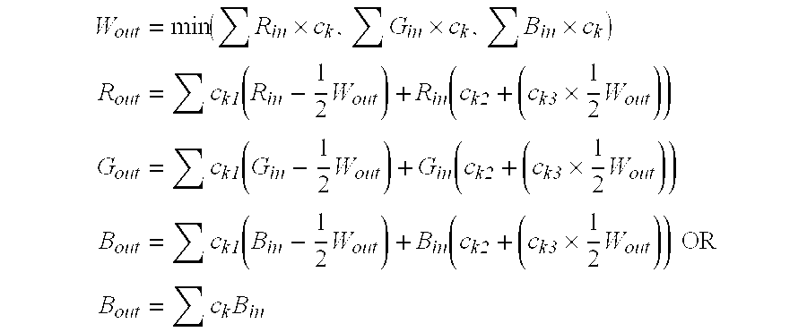
- Where: c k1 is the coefficient matrix for that portion that is overlapped by both the primary color resample area and the fourth color resample areas. ck2 is the coefficient matrix for the portion that is not overlapped by the fourth resample areas with respect to the total resample area for that reconstruction point. It is noted that ck3 is a modifier coefficient matrix whereby ck2+ck3=ckx−w, where ckx−w is the coefficient matrix that would be generated if the primary color resample area were restricted to only that area not overlapped by the fourth-color resample areas.
- The form of the expression allows the luminance energy in the overlapping resample area to be transferred to the fourth-color, while simultaneously increasing the effect of the non-overlapped area to ensure that when a full white field is present, that all of the subpixels are turned on full. The use of the constant of “one half (½)” as a multiplier for the fourth color data is because when the fourth color “borrows” luminance from both the red and green, it replaces only one half of the combined red and green total. The choice of using the simple or more complicated form of the formula for the blue component depends on the level of accuracy vs. computational complexity and cost that is tolerable. The blue image component has negligible luminance and may exhibit greater color error before it is noted by the Human Vision System. Thus, the simplification for the blue data may be acceptable.
- As before, where the fourth-color only represents two of the color planes, for example, blue and green, by using a cyan as the fourth-color, the algorithm is given below, wherein W out is the energy applied to the cyan color:

- The resample areas shown in FIGS. 24A and 24B treat all of the reconstruction areas exactly in the center of the colored subpixels shown in FIG. 22, as opposed to the resample areas shown in FIG. 23 that treat the red and green reconstruction points as though they were on an idealized checkerboard for computational simplicity. The value of treating the reconstruction points exactly is that the fourth-color subpixels, when considered along side the majority subpixels, may reconstruct the phase relationships of scaled input image data sets better than the idealized checkerboard of FIG. 23.
- Examining the meaning and relationships between the various coefficient matrices, using the example of the resample areas in FIGS. 24A and 24B: A randomly chosen example
green reconstruction point 2406 has an associatedresample area 2410. Next to it is a fourth-color reconstruction point 2408 and an associatedresample area 2440. Theresample area 2410 is divided into twosub-resample areas area 2420 of the fourth-color resample area 2440 and thegreen resample area 2410 is used to calculate the subpixel rendering coefficient matrix ck1 for the green subpixel associated with thereconstruction point 2406. The non-overlappinggreen resample area 2430 is used to calculate the subpixel rendering coefficient matrices ck2 and ck3 for the green subpixel associated with thereconstruction point 2406. - Some, in this instance half, of the green and red resample areas will overlap more than one fourth color resample area. For example, another
green reconstruction point 2456 has an associatedresample area 2450. This resample area is divided in foursub-resample areas resample area 2450, overlaps three of the nearby fourth-color resample areas color reconstruction points green resample area 2450 and the nearby fourth-color resample areas overlap areas 
- Where: c k11, ck12, and ck13, are the coefficient matrices for that portion that is overlapped by both the primary color resample area and the 3 fourth color resample areas. ck2 is the coefficient matrix for that portion that is not overlapped by the fourth resample areas with respect to the total resample area for that reconstruction point. ck31, ck32, and ck33, are modifier coefficient matrices whereby ck2+ck31+ck32+ck33=ckx−w, where ckx−w is the coefficient matrix that would be generated if the primary color resample area were restricted to only that area not overlapped by the fourth color resample areas. Wout-1 and Wout-2 and Wout-3 are calculated the same as Wout but from the three surrounding resample points—e.g.
points - Each implied sample area (for example, the orthogonal grid as shown in FIG. 23) from the input image data creates entries in the coefficient matrices. For each resample area, only the input data points that have an overlapping implied sample area have an entry in the associated coefficient matrix. Examining FIG. 24B, with reference where needed to FIG. 24A, an input image pixel's implied
sample area 2415 is shown overlapping thegreen resample area 2410 and the fourth-color resample area 2440. Theinput sample area 2415 is subdivided by the two overlapping resample areas. One sub-area of the impliedinput sample area 2415 is the overlap of theinput sample area 2415 and the intersection setoverlap 2420, that is itself the overlap of thegreen resample area 2410 and the fourth-color resample area 2440, to form a new, tripleintersection set area 2425. Thisarea 2425, when measured by a suitable integration, divided by the total area of thegreen resample area 2410, is the coefficient for the input image data point associated with the impliedsample area 2415 in the coefficient matrix ck1 for the green color subpixel associated with thegreen reconstruction point 2406. Another sub-area of the impliedinput sample area 2415 is the overlap with thegreen resample area 2410 not overlapping the fourth-color resample area 2430, forming a double intersectionset overlap area 2435. Thisarea 2435 divided by the area of thegreen resample area 2410 is the coefficient for the input image data point associated with the impliedsample area 2415 in the coefficient matrix ck2 for the green color subpixel associated with thegreen reconstruction point 2406. This same area divided by the non-fourth-color-overlap area 2430 is the coefficient in the phantom coefficient matrix ckx−w used to calculate the modifier coefficient in the coefficient matrix ck3. The rest of the coefficients in the various matrices are derived in like manner. - The complexity of the above algorithms can be avoided using a simplification in which the resample areas of both the red and green are reduced by the amount that is covered by the fourth-color resample area. Several methods of determining the area of the fourth-color resample are given below.
- One straight forward method of determine the area of the fourth-
color resample area 2580 associated with the fourth-color reconstruction point 2588 is to define it as the overlap of thered resample area 2540 associated with thered reconstruction point 2544 and thegreen resample area 2560 associated with thegreen reconstruction point 2566 as is shown in FIG. 25. The effectivered resample area 2542 is thus defined as theresample area 2540 not overlapping thegreen resample area 2560. The effectivegreen resample area 2562 is similarly defined as theresample area 2560 not overlapping thered resample area 2540. Thus, the fourth-color subpixel has an associatedresample area 2580 coverage of the input image data set to itself. The algorithm to subpixel render the data simplifies to:
- Where c k−w is the coefficient matrix for the effective resample area for the given color reconstruction point, considering it to be the only area covered.
- The above resample areas for the fourth-color cover the same, coincident, area in each of the color planes. This coincident area may be defined by some “natural” boundaries as above, or by fiat to some other shape or shapes. The fourth-color resample areas do not have to be coincident for each color plane. An example of which is described below.
- Examining FIG. 26, the
red resample areas 2640 associated with thered reconstruction points 2644 andgreen resample areas 2660 associated with green reconstruction points have been reduced in area to accommodate the fourth-color resample areas color resample areas 2680 that are resampling the red color plane is not coincident with the fourth-color resample areas 2689 that are resampling the green color plane. There areoverlap regions 2685 directly over the fourth-color reconstruction points. - The novel arrangement of resample areas shown in FIG. 26 is generated by a modification to the algorithm that is used to generate the resample areas shown in FIGS. 24A and 24B in which the fourth-color is treated as belonging to the set of reconstruction points for the majority colors. The method of generating the arrangements in FIGS. 24A and 24B is to “seed a crystal” at each reconstruction point within a color plane, then allowing the seed to grow isotropically in diameter until it “touches” another crystal, thus forming the boundaries of the resample areas. This generates boundaries in which a given random point is enclosed along with the nearest reconstruction point, in accordance with the teaching in '355 application. The modification to the resample area generation algorithm that generated FIG. 26 is both to include the fourth-color reconstruction points and to delay the start of the fourth-color “seed crystal” growth. By delaying the start of the “seed crystals” the fourth-color resample areas are reduced in area. The greater the delay, the smaller the fourth-color resample areas.
- To help illustrate some of the principles developed herein, the following is a numerical example of calculating filter coefficients. As such, this example is not offered to limit the scope of the present invention in anyway. Indeed other numerical example are possible from other configurations thus, the following is merely illustrative.
- In this example of how to calculate all the coefficient matrices described above, the case is considered where the implied input sample points are coincident with the resample points. This is true when the input image is not being scaled, or when there is one input sample point for each output red or green resample point.
- Consider the
resample areas sub-resample areas sub-resample area 2430 would be the intermediate coefficient matrix ckx−w mentioned above:
- This C kx−w matrix was calculated with respect to the sub-resample area but the Ck2 matrix must be calculated with respect to the whole resample area. This can be done by multiplying the Ckx−w matrix by the ratio of the sub-resample area over the whole resample area (4010/8712 in the case of
sub-resample area 2430 and whole resample area 2410). The result in case would be:
- In a similar procedure the
sub-resample area 2420 is measured to produce the coefficient matrix Ck1:
- Note that neither of these matrices sums to 256 but together they do. Some care must be taken when rounding the numbers to small integers to make sure that this relationship remains true.
- From the relationship c k2+ck3=ckx−w given above it is now possible to calculate the modifier coefficient matrix Ck3=Ckx−w−Ck2 giving the result below:

- In
resample area 2450 thesub-resample area 2455 lies outside threeoverlap areas area 2455 includes two separate areas that do not necessarily connect but must be taken into account. When the coefficient table for this area is built the result is another intermediate matrix:
- In this case even with multiple overlap areas there is still only one C k2 matrix and multiplying the above matrix by 4602/8712 (the ratio of the areas of
sub-resample area 2455 over the whole resample area 2450) results in:
- In the case of
resample area 2450 there are three overlappingsub-resample areas 
- Where C k11, Ck12 and Ck13 are the coefficient matrices for
sub-resample areas - Finally three modifier matrices must be calculated. C k31, Ck32 and Ck33 for
sub-resample areas 
- Each of the three modifiers is apportioned a fraction of this matrix according to the relative size of its area. In this example, the areas of
sub-resample areas 
- Examining FIG. 24A it is possible to see that all the other sub-resample areas are either identical to the ones described above, or are mirror images of the ones described. The coefficient matrices calculated in the above example can simply be flipped left-to-right to create a set of matrices for the mirrored resample areas. No more calculations are necessary to produce all the coefficients necessary for this example.
- All the above calculations were done with the assumption that the implied input sample points were coincident with the resample points. This is true when the input image is not being scaled, when there is one input sample point for each output red or green resample point. When the input image is being scaled the calculations are made more complex by the introduction of a “repeat cell” of coefficients. A different set of coefficients must be calculated for each cell of the repeat cell.
- The above use of transmissive liquid crystal displays as example embodiments is not to be construed as restricting the scope of this invention. It will be obvious to those skilled in the art, that adjusting the luminance and chrominance and positions of the emitters of non-transmissive display panels, such as reflective Liquid Crystal Displays, emissive Electro Luminescent Displays (EL), Plasma Display Panels (PDP), Field Emitter Displays (FED), Electrophoretic displays, Iridescent Displays (ID), Incandescent Displays, solid state Light Emitting Diode (LED) display, and Organic Light Emitting Diode (OLED) displays, will also be improved using this teaching and are to be considered within the scope of the present invention. Variations on the resample area definitions, coefficient matrices, and algorithms may suggest themselves to those knowledgeable in the art and should be considered to be within the scope of the present invention.
- The foregoing description has not been limited to a specific embodiment of this invention. It will be apparent, however, that various variations and modifications may be made to the invention, with the attainment of some or all of the advantages of the invention. It is the object of the appended claims to cover these and such other variations and modifications as come within the true spirit and scope of the invention.
- Other embodiments of the invention will be apparent from consideration of the specification and practice of the invention disclosed herein. It is intended that the specification and examples be considered as exemplary only, with a true scope and spirit of the invention being indicated by the following claims.
Claims (41)


Priority Applications (27)
| Application Number | Priority Date | Filing Date | Title |
|---|---|---|---|
| US10/243,094 US20040051724A1 (en) | 2002-09-13 | 2002-09-13 | Four color arrangements of emitters for subpixel rendering |
| US10/278,353 US7492379B2 (en) | 2002-01-07 | 2002-10-22 | Color flat panel display sub-pixel arrangements and layouts for sub-pixel rendering with increased modulation transfer function response |
| CN200810130399XA CN101325027B (en) | 2002-01-07 | 2002-12-13 | Color flat panel display sub-pixel arrangements and sub-pixel coloring device |
| TW091136109A TWI276886B (en) | 2002-01-07 | 2002-12-13 | Improvements to color flat panel display sub-pixel arrangements and layouts for sub-pixel rendering with increased modulation transfer function response |
| KR1020047010456A KR100906632B1 (en) | 2002-01-07 | 2002-12-13 | Display comprising a plurality of a sub-pixel group, a system comprising such a display, and a method of converting a source pixel data |
| AU2002353143A AU2002353143A1 (en) | 2002-01-07 | 2002-12-13 | Color flat panel display sub-pixel arrangements and layouts for sub-pixel rendering with increased modulation transfer function |
| EP10184890.1A EP2270579B1 (en) | 2002-01-07 | 2002-12-13 | Color flat panel display sub-pixel arrangements and layouts for sub-pixel rendering with increased modulation transfer function |
| EP02790121.4A EP1461800B1 (en) | 2002-01-07 | 2002-12-13 | Color flat panel display sub-pixel arrangements and layouts for sub-pixel rendering with increased modulation transfer function |
| CNB028268636A CN100439989C (en) | 2002-01-07 | 2002-12-13 | Color flat panel display sub-pixel arrangements and layouts for sub-pixel rendering |
| JP2003560892A JP4299672B2 (en) | 2002-01-07 | 2002-12-13 | Color flat panel display subpixel configuration and layout for subpixel rendering with improved modulation transfer function |
| CN2008101304009A CN101325028B (en) | 2002-01-07 | 2002-12-13 | Color flat panel display sub-pixel arrangements and sub-pixel coloring device |
| CN2008101303970A CN101325026B (en) | 2002-01-07 | 2002-12-13 | Color flat panel display sub-pixel arrangements and sub-pixel coloring device |
| CN2008101303966A CN101325025B (en) | 2002-01-07 | 2002-12-13 | Color flat panel display sub-pixel arrangements and sub-pixel coloring device |
| PCT/US2002/039864 WO2003060870A1 (en) | 2002-01-07 | 2002-12-13 | Color flat panel display sub-pixel arrangements and layouts for sub-pixel rendering with increased modulation transfer function |
| AU2003270455A AU2003270455A1 (en) | 2002-09-13 | 2003-09-11 | Multi color arrangements for subpixel rendering |
| KR1020107019460A KR101066416B1 (en) | 2002-09-13 | 2003-09-11 | Improved four color arrangements of emitters for subpixel rendering |
| KR1020107019457A KR101066420B1 (en) | 2002-09-13 | 2003-09-11 | Improved four color arrangements of emitters for subpixel rendering |
| KR1020107019458A KR101066413B1 (en) | 2002-09-13 | 2003-09-11 | Improved four color arrangements of emitters for subpixel rendering |
| CNB03821461XA CN100510883C (en) | 2002-09-13 | 2003-09-11 | Improved four color arrangements of emitters for subpixel rendering |
| KR1020057004231A KR101010004B1 (en) | 2002-09-13 | 2003-09-11 | Improved four color arrangements of emitters for subpixel rendering |
| PCT/US2003/028222 WO2004025611A2 (en) | 2002-09-13 | 2003-09-11 | Multi color arrangements for subpixel rendering |
| EP03752148A EP1579409A2 (en) | 2002-09-13 | 2003-09-11 | Multicolor arrangements for subpixel rendering |
| TW092125240A TWI360100B (en) | 2002-09-13 | 2003-09-12 | Improved displays for subpixel rendering |
| TW100141805A TWI449023B (en) | 2002-09-13 | 2003-09-12 | Improved displays for subpixel rendering |
| US11/469,431 US7573493B2 (en) | 2002-09-13 | 2006-08-31 | Four color arrangements of emitters for subpixel rendering |
| US11/469,458 US7701476B2 (en) | 2002-09-13 | 2006-08-31 | Four color arrangements of emitters for subpixel rendering |
| US12/715,355 US8294741B2 (en) | 2002-09-13 | 2010-03-01 | Four color arrangements of emitters for subpixel rendering |
Applications Claiming Priority (1)
| Application Number | Priority Date | Filing Date | Title |
|---|---|---|---|
| US10/243,094 US20040051724A1 (en) | 2002-09-13 | 2002-09-13 | Four color arrangements of emitters for subpixel rendering |
Related Child Applications (3)
| Application Number | Title | Priority Date | Filing Date |
|---|---|---|---|
| US10/278,353 Continuation-In-Part US7492379B2 (en) | 2002-01-07 | 2002-10-22 | Color flat panel display sub-pixel arrangements and layouts for sub-pixel rendering with increased modulation transfer function response |
| US11/469,431 Division US7573493B2 (en) | 2002-09-13 | 2006-08-31 | Four color arrangements of emitters for subpixel rendering |
| US11/469,458 Continuation US7701476B2 (en) | 2002-09-13 | 2006-08-31 | Four color arrangements of emitters for subpixel rendering |
Publications (1)
| Publication Number | Publication Date |
|---|---|
| US20040051724A1 true US20040051724A1 (en) | 2004-03-18 |
Family
ID=31991549
Family Applications (4)
| Application Number | Title | Priority Date | Filing Date |
|---|---|---|---|
| US10/243,094 Abandoned US20040051724A1 (en) | 2002-01-07 | 2002-09-13 | Four color arrangements of emitters for subpixel rendering |
| US11/469,431 Expired - Lifetime US7573493B2 (en) | 2002-09-13 | 2006-08-31 | Four color arrangements of emitters for subpixel rendering |
| US11/469,458 Active 2024-10-17 US7701476B2 (en) | 2002-09-13 | 2006-08-31 | Four color arrangements of emitters for subpixel rendering |
| US12/715,355 Expired - Lifetime US8294741B2 (en) | 2002-09-13 | 2010-03-01 | Four color arrangements of emitters for subpixel rendering |
Family Applications After (3)
| Application Number | Title | Priority Date | Filing Date |
|---|---|---|---|
| US11/469,431 Expired - Lifetime US7573493B2 (en) | 2002-09-13 | 2006-08-31 | Four color arrangements of emitters for subpixel rendering |
| US11/469,458 Active 2024-10-17 US7701476B2 (en) | 2002-09-13 | 2006-08-31 | Four color arrangements of emitters for subpixel rendering |
| US12/715,355 Expired - Lifetime US8294741B2 (en) | 2002-09-13 | 2010-03-01 | Four color arrangements of emitters for subpixel rendering |
Country Status (7)
| Country | Link |
|---|---|
| US (4) | US20040051724A1 (en) |
| EP (1) | EP1579409A2 (en) |
| KR (4) | KR101066416B1 (en) |
| CN (1) | CN100510883C (en) |
| AU (1) | AU2003270455A1 (en) |
| TW (2) | TWI360100B (en) |
| WO (1) | WO2004025611A2 (en) |
Cited By (103)
| Publication number | Priority date | Publication date | Assignee | Title |
|---|---|---|---|---|
| US20030034992A1 (en) * | 2001-05-09 | 2003-02-20 | Clairvoyante Laboratories, Inc. | Conversion of a sub-pixel format data to another sub-pixel data format |
| US20030128225A1 (en) * | 2002-01-07 | 2003-07-10 | Credelle Thomas Lloyd | Color flat panel display sub-pixel arrangements and layouts for sub-pixel rendering with increased modulation transfer function response |
| US20030128179A1 (en) * | 2002-01-07 | 2003-07-10 | Credelle Thomas Lloyd | Color flat panel display sub-pixel arrangements and layouts for sub-pixel rendering with split blue sub-pixels |
| US20040080479A1 (en) * | 2002-10-22 | 2004-04-29 | Credelle Thomas Lioyd | Sub-pixel arrangements for striped displays and methods and systems for sub-pixel rendering same |
| US20040178973A1 (en) * | 2003-03-13 | 2004-09-16 | Eastman Kodak Company | Color OLED display system |
| US20040178743A1 (en) * | 2002-12-16 | 2004-09-16 | Eastman Kodak Company | Color OLED display system having improved performance |
| US20040178974A1 (en) * | 2002-12-16 | 2004-09-16 | Eastman Kodak Company | Color OLED display system having improved performance |
| US20050001542A1 (en) * | 2003-05-01 | 2005-01-06 | Hiroshi Kiguchi | Organic electroluminescent device and electronic apparatus |
| US20050062767A1 (en) * | 2003-09-19 | 2005-03-24 | Samsung Electronics Co., Ltd. | Method and apparatus for displaying image and computer-readable recording medium for storing computer program |
| US20050083296A1 (en) * | 2001-11-09 | 2005-04-21 | Daly Scott J. | Liquid crystal display backlight with modulation |
| US20050117186A1 (en) * | 2003-11-21 | 2005-06-02 | Baoxin Li | Liquid crystal display with adaptive color |
| US20050127819A1 (en) * | 2003-12-12 | 2005-06-16 | Hisashi Ohtani | Light emitting device |
| US20050140907A1 (en) * | 2003-12-29 | 2005-06-30 | Jae-Kyeong Yun | Liquid crystal display device automatically adjusting aperture ratio in each pixel |
| US20050140906A1 (en) * | 2003-12-26 | 2005-06-30 | Lg.Philips Lcd Co., Ltd. | Liquid crystal display device and a display device |
| US20050151462A1 (en) * | 2003-12-17 | 2005-07-14 | Semiconductor Energy Laboratory Co., Ltd. | Display device and manufacturing method thereof |
| US20050162600A1 (en) * | 2002-08-14 | 2005-07-28 | Soo-Guy Rho | Liquid crystal display |
| US20050225575A1 (en) * | 2004-04-09 | 2005-10-13 | Clairvoyante, Inc | Novel subpixel layouts and arrangements for high brightness displays |
| US20050225563A1 (en) * | 2004-04-09 | 2005-10-13 | Clairvoyante, Inc | Subpixel rendering filters for high brightness subpixel layouts |
| US20050237450A1 (en) * | 2004-04-27 | 2005-10-27 | Chih-Jen Hu | Liquid crystal panel with improved chromaticity and brightness |
| US20050248520A1 (en) * | 2004-05-04 | 2005-11-10 | Sharp Laboratories Of America, Inc. | Liquid crystal display with temporal black point |
| US20050248524A1 (en) * | 2004-05-04 | 2005-11-10 | Sharp Laboratories Of America, Inc. | Liquid crystal display with colored backlight |
| US20050248555A1 (en) * | 2004-05-04 | 2005-11-10 | Sharp Laboratories Of America, Inc. | Liquid crystal display with illumination control |
| US20050248553A1 (en) * | 2004-05-04 | 2005-11-10 | Sharp Laboratories Of America, Inc. | Adaptive flicker and motion blur control |
| US20050248593A1 (en) * | 2004-05-04 | 2005-11-10 | Sharp Laboratories Of America, Inc. | Liquid crystal display with modulated black point |
| US20050248554A1 (en) * | 2004-05-04 | 2005-11-10 | Sharp Laboratories Of America, Inc. | Liquid crystal display with filtered black point |
| US20050248591A1 (en) * | 2004-05-04 | 2005-11-10 | Sharp Laboratories Of America, Inc. | Liquid crystal display with adaptive width |
| US20050275610A1 (en) * | 2004-05-31 | 2005-12-15 | Nam-Seok Roh | Liquid crystal display device and driving method for the same |
| US20050285996A1 (en) * | 2004-06-23 | 2005-12-29 | Sharp Kabushiki Kaisha | Liquid crystal display device and producing method thereof |
| US20060087866A1 (en) * | 2004-10-22 | 2006-04-27 | Ng Kee Y | LED backlight |
| US20060103621A1 (en) * | 2004-11-16 | 2006-05-18 | Sharp Laboratories Of America, Inc. | Technique that preserves specular highlights |
| US20060103615A1 (en) * | 2004-10-29 | 2006-05-18 | Ming-Chia Shih | Color display |
| US20060104533A1 (en) * | 2004-11-16 | 2006-05-18 | Sharp Laboratories Of America, Inc. | High dynamic range images from low dynamic range images |
| US20060152524A1 (en) * | 2005-01-12 | 2006-07-13 | Eastman Kodak Company | Four color digital cinema system with extended color gamut and copy protection |
| US20060158454A1 (en) * | 2003-01-28 | 2006-07-20 | Heynderickx Ingrid Emilienne J | Method of displaying an image on a color display |
| US20060181503A1 (en) * | 2005-02-17 | 2006-08-17 | Sharp Laboratories Of America, Inc. | Black point insertion |
| EP1705635A2 (en) * | 2005-03-24 | 2006-09-27 | Sanyo Epson Imaging Devices Corporation | Image display device with appropriate subpixel driving based on discrimination of colour/black and white images and electronic apparatus including the same |
| US20060284872A1 (en) * | 2005-06-15 | 2006-12-21 | Clairvoyante, Inc | Improved Bichromatic Display |
| US20070008461A1 (en) * | 2005-07-07 | 2007-01-11 | Sanyo Epson Imaging Devices Corporation | Electro-optical device and electronic apparatus |
| US20070008463A1 (en) * | 2005-07-06 | 2007-01-11 | Sanyo Epson Imaging Devices Corporation | Liquid crystal display device and electronic apparatus |
| US20070013649A1 (en) * | 2005-07-14 | 2007-01-18 | Samsung Electronics Co., Ltd. | Electrophoretic display device with improved reflective luminance |
| WO2006127555A3 (en) * | 2005-05-20 | 2007-03-22 | Clairvoyante Inc | Multiprimary color subpixel rendering with metameric filtering |
| US20070085789A1 (en) * | 2003-09-30 | 2007-04-19 | Koninklijke Philips Electronics N.V. | Multiple primary color display system and method of display using multiple primary colors |
| WO2007047537A2 (en) | 2005-10-14 | 2007-04-26 | Clairvoyante, Inc. | Improved gamut mapping and subpixel rendering systems and methods |
| US20070090748A1 (en) * | 2005-10-24 | 2007-04-26 | Canon Kabushiki Kaisha | Phosphor material, light emitting member and image display apparatus using the same |
| WO2007047534A1 (en) | 2005-10-14 | 2007-04-26 | Clairvoyante, Inc. | Improved memory structures for image processing |
| US7230594B2 (en) * | 2002-12-16 | 2007-06-12 | Eastman Kodak Company | Color OLED display with improved power efficiency |
| US20070171443A1 (en) * | 2006-01-24 | 2007-07-26 | Sharp Laboratories Of America, Inc. | Color enhancement technique using skin color detection |
| US20070172118A1 (en) * | 2006-01-24 | 2007-07-26 | Sharp Laboratories Of America, Inc. | Method for reducing enhancement of artifacts and noise in image color enhancement |
| US20070205972A1 (en) * | 2004-12-15 | 2007-09-06 | Canon Kabushiki Kaisha | Color display device |
| US20070257943A1 (en) * | 2006-05-08 | 2007-11-08 | Eastman Kodak Company | Method for rendering color EL display and display device with improved resolution |
| US20070263257A1 (en) * | 2006-05-11 | 2007-11-15 | Feng-Ting Pai | Hybrid frame rate control method and architecture for a display |
| US20070268429A1 (en) * | 2006-05-18 | 2007-11-22 | Lg. Philips Lcd Co., Ltd. | Liquid crystal display and method for providing light to liquid crystal panel |
| US7333080B2 (en) | 2004-03-29 | 2008-02-19 | Eastman Kodak Company | Color OLED display with improved power efficiency |
| US20080049047A1 (en) * | 2006-08-28 | 2008-02-28 | Clairvoyante, Inc | Subpixel layouts for high brightness displays and systems |
| US20080049048A1 (en) * | 2006-08-28 | 2008-02-28 | Clairvoyante, Inc | Subpixel layouts for high brightness displays and systems |
| US20080079755A1 (en) * | 2004-12-27 | 2008-04-03 | Sharp Kabushiki Kaisha | Driving Device for Display Panel, Display Device Including the Driving Device, Method for Driving a Display Panel, Program, and Storage Medium |
| US20080111799A1 (en) * | 2004-05-25 | 2008-05-15 | Koninklijke Philips Electronics, N.V. | Driving an electroluminescent display |
| US20080129677A1 (en) * | 2006-11-30 | 2008-06-05 | Sharp Laboratories Of America, Inc. | Liquid crystal display with area adaptive backlight |
| US20080170083A1 (en) * | 2005-04-04 | 2008-07-17 | Clairvoyante, Inc | Efficient Memory Structure for Display System with Novel Subpixel Structures |
| US7511716B2 (en) | 2005-04-29 | 2009-03-31 | Sony Corporation | High-resolution micro-lens 3D display with shared sub-pixel color signals |
| EP2051229A2 (en) | 2007-10-09 | 2009-04-22 | Samsung Electronics Co., Ltd. | Systems and methods for selective handling of out-of-gamut color conversions |
| US20090115803A1 (en) * | 2006-05-24 | 2009-05-07 | Koninklijke Philips Electronics N.V. | Optimal backlighting determination apparatus and method |
| US20090140950A1 (en) * | 2007-11-29 | 2009-06-04 | Jong-Hoon Woo | Display device having multiple viewing zones and method of displaying multiple images |
| US20090207103A1 (en) * | 2008-02-15 | 2009-08-20 | Igor Gregory Mative | Light-emitting hologram based on Organic Polymeric Diode - (OLED/PLED) |
| US20100118045A1 (en) * | 2007-02-13 | 2010-05-13 | Candice Hellen Brown Elliott | Subpixel layouts and subpixel rendering methods for directional displays and systems |
| US7755652B2 (en) | 2002-01-07 | 2010-07-13 | Samsung Electronics Co., Ltd. | Color flat panel display sub-pixel rendering and driver configuration for sub-pixel arrangements with split sub-pixels |
| US7791679B2 (en) | 2003-06-06 | 2010-09-07 | Samsung Electronics Co., Ltd. | Alternative thin film transistors for liquid crystal displays |
| US20100259569A1 (en) * | 2009-04-10 | 2010-10-14 | Hitachi Displays, Ltd. | Display signal conversion apparatus |
| US20110043552A1 (en) * | 2009-08-24 | 2011-02-24 | Candice Hellen Brown Elliott | Subpixel rendering with color coordinates' weights depending on tests performed on pixels |
| US20110043553A1 (en) * | 2009-08-24 | 2011-02-24 | Samsung Electronics Co., Ltd. | Gamut mapping which takes into account pixels in adjacent areas of a display unit |
| US20110043533A1 (en) * | 2009-08-24 | 2011-02-24 | Seok Jin Han | Supbixel rendering suitable for updating an image with a new portion |
| US20110057950A1 (en) * | 2009-09-07 | 2011-03-10 | Samsung Electronics Co., Ltd | Data processing device, display system including the same and method of processing data |
| US20110090227A1 (en) * | 2008-06-10 | 2011-04-21 | Hewlett-Packard Development Company | Point Selector For Graphical Displays |
| US7944423B2 (en) | 2004-07-01 | 2011-05-17 | Sony Corporation | Image processing unit with black-and-white line segment pattern detection, image processing method, image display device using such image processing unit, and electronic apparatus using such image display device |
| US8050511B2 (en) | 2004-11-16 | 2011-11-01 | Sharp Laboratories Of America, Inc. | High dynamic range images from low dynamic range images |
| EP2439729A2 (en) | 2006-06-02 | 2012-04-11 | Samsung Electronics Co., Ltd. | Field sequential color display system having multiple segmented backlight |
| USRE43574E1 (en) * | 2002-11-20 | 2012-08-14 | Samsung Electronics Co., Ltd. | Four color liquid crystal display and panel therefor |
| US20120262496A1 (en) * | 2011-04-18 | 2012-10-18 | Jerzy Wieslaw Swic | Mapping Input Component Colors Directly to Waveforms |
| WO2013079217A1 (en) | 2011-11-30 | 2013-06-06 | Novaled Ag | Display |
| US20140240205A1 (en) * | 2010-10-18 | 2014-08-28 | Vp Assets Limited | Image device with pixel dots with multi-primary colors |
| US8848294B2 (en) | 2010-05-20 | 2014-09-30 | Qualcomm Mems Technologies, Inc. | Method and structure capable of changing color saturation |
| TWI457675B (en) * | 2011-08-29 | 2014-10-21 | Au Optronics Corp | Pixel structure, liquid crystal display panel and transparent liquid crystal display device |
| US20150029208A1 (en) * | 2013-07-25 | 2015-01-29 | Samsung Display Co., Ltd. | Pixel array structure and display apparatus including the same |
| US8988454B2 (en) | 2007-10-25 | 2015-03-24 | Stmicroelectronics (Grenoble 2) Sas | Method for processing a digital video stream and corresponding device |
| US9123681B2 (en) | 2012-08-09 | 2015-09-01 | Au Optronics Corporation | Display panel |
| US20160120004A1 (en) * | 2013-10-30 | 2016-04-28 | Au Optronics Corp. | Pixel arrangement of color display panel |
| US9335853B2 (en) | 2011-08-16 | 2016-05-10 | Samsung Display Co., Ltd. | Display device including sensor units and driving method thereof |
| JP2016102934A (en) * | 2014-11-28 | 2016-06-02 | 株式会社ジャパンディスプレイ | Display device |
| US20160232829A1 (en) * | 2015-02-06 | 2016-08-11 | Samsung Display Co., Ltd | Display apparatus |
| US20160306237A1 (en) * | 2015-04-14 | 2016-10-20 | Japan Display Inc. | Display device |
| US20160343284A1 (en) * | 2014-12-30 | 2016-11-24 | Boe Technology Group Co., Ltd | Pixel structure and displaying method thereof, and related display apparatus |
| US20170059944A1 (en) * | 2014-04-18 | 2017-03-02 | Shenzhen China Star Optoelectronics Technology Co., Ltd. | Pixel electrode unit, display panel and liquid crystal display device |
| US20170084672A1 (en) * | 2004-12-16 | 2017-03-23 | Semiconductor Energy Laboratory Co., Ltd. | Light-Emitting Device and Electronic Device Using the Same |
| US9728116B2 (en) | 2014-07-31 | 2017-08-08 | Samsung Display Co., Ltd. | Display apparatus and method of driving the same |
| US9792877B2 (en) | 2013-04-12 | 2017-10-17 | Samsung Display Co., Ltd | Data processing device and display system including the same |
| US9812054B2 (en) | 2014-12-05 | 2017-11-07 | Novatek Microelectronics Corp. | Display driver and display apparatus using sub-pixel rendering method |
| US9978321B2 (en) | 2015-08-10 | 2018-05-22 | Japan Display Inc. | Display device and method of driving the same |
| EP3217389A4 (en) * | 2014-11-04 | 2018-06-20 | Boe Technology Group Co. Ltd. | Pixel structure and driving method therefor, and display apparatus |
| US10325540B2 (en) * | 2014-10-27 | 2019-06-18 | Shanghai Avic Optoelectronics Co., Ltd. | Pixel structure, display panel and pixel compensation method therefor |
| CN111613165A (en) * | 2019-02-23 | 2020-09-01 | 华为技术有限公司 | Method and electronic device for displaying image in multi-display driving circuit system |
| US10909953B2 (en) * | 2015-08-19 | 2021-02-02 | Japan Display Inc. | Display device |
| US11367376B2 (en) * | 2017-08-31 | 2022-06-21 | Kunshan Go-Visionox Opto-Electronics Co., Ltd. | Display panel and display device |
| US11749171B2 (en) | 2019-02-23 | 2023-09-05 | Huawei Technologies Co., Ltd. | Method for displaying image in multi display drive circuit system and electronic device |
Families Citing this family (76)
| Publication number | Priority date | Publication date | Assignee | Title |
|---|---|---|---|---|
| KR100951350B1 (en) | 2003-04-17 | 2010-04-08 | 삼성전자주식회사 | Liquid crystal display |
| US7495722B2 (en) * | 2003-12-15 | 2009-02-24 | Genoa Color Technologies Ltd. | Multi-color liquid crystal display |
| KR101015275B1 (en) * | 2004-06-22 | 2011-02-15 | 엘지디스플레이 주식회사 | Large size display device of tild method |
| SG155994A1 (en) * | 2004-09-27 | 2009-10-29 | Idc Llc | Method and device for manipulating color in a display |
| JP5014139B2 (en) * | 2005-09-21 | 2012-08-29 | シャープ株式会社 | Display device and color filter substrate |
| TWI381742B (en) * | 2005-10-13 | 2013-01-01 | Seiko Epson Corp | Image display device, electronic apparatus, and pixel location determining method |
| US8587621B2 (en) * | 2005-11-28 | 2013-11-19 | Genoa Color Technologies Ltd. | Sub-pixel rendering of a multiprimary image |
| US9928786B2 (en) * | 2006-10-13 | 2018-03-27 | Sharp Kabushiki Kaisha | Display device and signal converting device |
| TW200821635A (en) * | 2006-11-03 | 2008-05-16 | Wintek Corp | Color filter structure and displaying panel using the same and displaying method thereof |
| US20080106678A1 (en) * | 2006-11-03 | 2008-05-08 | Wintek Corporation | Color filter structure and displaying panel using the same and displaying method thereof |
| CN101636775B (en) * | 2007-03-16 | 2014-05-07 | 夏普株式会社 | Display device |
| JP2008270936A (en) * | 2007-04-17 | 2008-11-06 | Nec Electronics Corp | Image output device and image display device |
| KR101360124B1 (en) | 2007-05-02 | 2014-02-07 | 삼성디스플레이 주식회사 | Display apparatus having pixel improved brightness and contrast ratio |
| US8456483B2 (en) * | 2007-05-18 | 2013-06-04 | Samsung Display Co., Ltd. | Image color balance adjustment for display panels with 2D subixel layouts |
| US7567370B2 (en) * | 2007-07-26 | 2009-07-28 | Hewlett-Packard Development Company, L.P. | Color display having layer dependent spatial resolution and related method |
| JP5044656B2 (en) * | 2007-09-13 | 2012-10-10 | シャープ株式会社 | Multi-primary color LCD |
| TWI326862B (en) * | 2007-09-28 | 2010-07-01 | Au Optronics Corp | Multi-primary color display |
| WO2009100350A1 (en) * | 2008-02-08 | 2009-08-13 | Raytheon Company | Electrophoretic light modulator |
| KR100926635B1 (en) * | 2008-05-28 | 2009-11-13 | 삼성모바일디스플레이주식회사 | Organic Light Emitting Display and Driving Method Thereof |
| JP4548520B2 (en) * | 2008-07-02 | 2010-09-22 | ソニー株式会社 | Coefficient generation apparatus and method, image generation apparatus and method, and program |
| US7894123B2 (en) * | 2009-02-27 | 2011-02-22 | Raytheon Company | Multilayer light modulator |
| US8378958B2 (en) * | 2009-03-24 | 2013-02-19 | Apple Inc. | White point control in backlights |
| US8351724B2 (en) * | 2009-05-08 | 2013-01-08 | Sharp Laboratories Of America, Inc. | Blue sky color detection technique |
| TW201040906A (en) * | 2009-05-11 | 2010-11-16 | Novatek Microelectronics Corp | Liquid crystal display panel and display devices |
| US20120062585A1 (en) * | 2009-05-19 | 2012-03-15 | Mitsubishi Electric Corporation | Vector graphic drawing device |
| JP5650918B2 (en) | 2010-03-26 | 2015-01-07 | 株式会社ジャパンディスプレイ | Image display device |
| US8803767B2 (en) | 2010-10-18 | 2014-08-12 | Vp Assets Limited | Image device with pixels arranged for white balance |
| US8670171B2 (en) | 2010-10-18 | 2014-03-11 | Qualcomm Mems Technologies, Inc. | Display having an embedded microlens array |
| US8873129B2 (en) | 2011-04-07 | 2014-10-28 | E Ink Corporation | Tetrachromatic color filter array for reflective display |
| CN104992654B (en) | 2011-07-29 | 2019-02-22 | 深圳云英谷科技有限公司 | The arrangement of subpixels and its rendering method of display |
| KR101787450B1 (en) | 2011-08-09 | 2017-10-19 | 삼성디스플레이 주식회사 | Display apparatus |
| TWI467527B (en) | 2011-11-25 | 2015-01-01 | Au Optronics Corp | Display device |
| CN103135296B (en) * | 2011-11-30 | 2015-12-16 | 上海中航光电子有限公司 | A kind of thin-film transistor LCD device array substrate |
| CN103135300B (en) * | 2011-11-30 | 2015-09-23 | 上海中航光电子有限公司 | A kind of thin-film transistor LCD device array substrate |
| KR20130066129A (en) * | 2011-12-12 | 2013-06-20 | 삼성디스플레이 주식회사 | A backlight unit and a method for driving the same |
| US9165526B2 (en) | 2012-02-28 | 2015-10-20 | Shenzhen Yunyinggu Technology Co., Ltd. | Subpixel arrangements of displays and method for rendering the same |
| KR101615332B1 (en) | 2012-03-06 | 2016-04-26 | 삼성디스플레이 주식회사 | Pixel arrangement structure for organic light emitting display device |
| US10832616B2 (en) | 2012-03-06 | 2020-11-10 | Samsung Display Co., Ltd. | Pixel arrangement structure for organic light emitting diode display |
| CN103474021B (en) * | 2012-06-07 | 2016-03-16 | 成卓 | A kind of method increasing display color gamut of LED display screen |
| KR102063973B1 (en) * | 2012-09-12 | 2020-01-09 | 삼성디스플레이 주식회사 | Organic Light Emitting Display Device and Driving Method Thereof |
| KR101971924B1 (en) | 2012-10-05 | 2019-04-25 | 삼성디스플레이 주식회사 | Display Device and Method of Driving thereof |
| KR102190843B1 (en) | 2013-07-09 | 2020-12-15 | 삼성디스플레이 주식회사 | Unit pixel and organic light emitting display device having the same |
| TWI507804B (en) | 2013-10-18 | 2015-11-11 | E Ink Holdings Inc | Electrophoretic display apparatus |
| TWI515891B (en) | 2013-11-01 | 2016-01-01 | 友達光電股份有限公司 | Display panel |
| KR102159749B1 (en) | 2014-01-27 | 2020-09-25 | 삼성디스플레이 주식회사 | Display device |
| TWI550847B (en) * | 2014-04-23 | 2016-09-21 | 財團法人工業技術研究院 | Pixel structure and electroluminescent display having the same |
| CN104090415B (en) * | 2014-07-01 | 2017-10-10 | 京东方科技集团股份有限公司 | Color membrane substrates and display device |
| TWI587041B (en) | 2014-12-02 | 2017-06-11 | 聯詠科技股份有限公司 | Display device and driving module thereof |
| TWI574078B (en) | 2014-12-02 | 2017-03-11 | 聯詠科技股份有限公司 | Display device and driving module thereof |
| TWI556048B (en) * | 2014-12-02 | 2016-11-01 | 聯詠科技股份有限公司 | Display device and driving module thereof |
| TWI557720B (en) * | 2014-12-05 | 2016-11-11 | 聯詠科技股份有限公司 | Display driver and display apparatus |
| CN104614909B (en) | 2015-02-06 | 2017-07-21 | 京东方科技集团股份有限公司 | Display panel and display device |
| CN106033657B (en) * | 2015-03-13 | 2019-09-24 | 联咏科技股份有限公司 | Display device and display driving method |
| CN104658433B (en) * | 2015-03-18 | 2017-09-22 | 京东方科技集团股份有限公司 | A kind of pixel arrangement structure, display device and display methods |
| CN104680945B (en) * | 2015-03-23 | 2018-05-29 | 京东方科技集团股份有限公司 | Pixel arrangement method, pixel rendering method and image display device |
| US20160291376A1 (en) * | 2015-03-30 | 2016-10-06 | Innolux Corporation | Display device |
| US9887247B2 (en) * | 2015-04-30 | 2018-02-06 | Novatek Microelectronics Corp. | Sub-pixel arrangement structure of organic light emitting diode display |
| CN105096805B (en) * | 2015-08-28 | 2018-06-05 | 厦门天马微电子有限公司 | Display device and sub-pixel rendering intent |
| CN105096806B (en) * | 2015-08-28 | 2017-09-15 | 厦门天马微电子有限公司 | The arrangement of subpixels and its color method of display |
| KR102494765B1 (en) | 2015-12-24 | 2023-02-02 | 삼성디스플레이 주식회사 | Display device |
| CN105530051A (en) * | 2015-12-31 | 2016-04-27 | 固安翌光科技有限公司 | OLED (organic light emitting diode) light source structure for light fidelity and light communication system thereof |
| US10151862B2 (en) * | 2016-04-27 | 2018-12-11 | Visera Technologies Company Limited | Color filter array having low density of blue color |
| CN108269535B (en) * | 2016-12-30 | 2020-07-07 | 上海和辉光电有限公司 | Display method and display device |
| CN106707627A (en) * | 2017-03-27 | 2017-05-24 | 京东方科技集团股份有限公司 | Array substrate, display panel and display device |
| US10768469B2 (en) * | 2017-04-28 | 2020-09-08 | Japan Display Inc. | Active matrix display device |
| JP2018189777A (en) | 2017-05-01 | 2018-11-29 | 株式会社ジャパンディスプレイ | Display device |
| CN106991957B (en) * | 2017-06-07 | 2020-02-21 | 京东方科技集团股份有限公司 | Pixel structure, display substrate, display device and display method |
| CN107515487A (en) * | 2017-09-08 | 2017-12-26 | 深圳市华星光电技术有限公司 | A kind of display panel and display device |
| US10283086B1 (en) | 2017-11-06 | 2019-05-07 | Novatek Microelectronics Corp. | Display device with novel sub-pixel configuration |
| CN108154848B (en) * | 2018-01-19 | 2020-11-17 | 昆山国显光电有限公司 | Display method and device for pixel arrangement and display equipment |
| RU2711121C1 (en) * | 2018-08-14 | 2020-01-15 | Александр Георгиевич Носков | Complex of four-color digital television full colours |
| CN109859685B (en) * | 2019-01-30 | 2021-03-16 | 武汉华星光电半导体显示技术有限公司 | Pixel arrangement of organic light emitting diode display |
| CN109616074B (en) * | 2019-01-31 | 2021-04-13 | 厦门天马微电子有限公司 | Display method and display device |
| US10861369B2 (en) * | 2019-04-09 | 2020-12-08 | Facebook Technologies, Llc | Resolution reduction of color channels of display devices |
| US10867543B2 (en) | 2019-04-09 | 2020-12-15 | Facebook Technologies, Llc | Resolution reduction of color channels of display devices |
| CN110308582B (en) * | 2019-06-29 | 2022-03-22 | 上海中航光电子有限公司 | Display device sequence and manufacturing method thereof |
Citations (87)
| Publication number | Priority date | Publication date | Assignee | Title |
|---|---|---|---|---|
| US3971065A (en) * | 1975-03-05 | 1976-07-20 | Eastman Kodak Company | Color imaging array |
| US4593978A (en) * | 1983-03-18 | 1986-06-10 | Thomson-Csf | Smectic liquid crystal color display screen |
| US4632514A (en) * | 1984-01-31 | 1986-12-30 | Matsushita Electric Industrial Co., Ltd. | Color liquid crystal display apparatus |
| US4642619A (en) * | 1982-12-15 | 1987-02-10 | Citizen Watch Co., Ltd. | Non-light-emitting liquid crystal color display device |
| US4651148A (en) * | 1983-09-08 | 1987-03-17 | Sharp Kabushiki Kaisha | Liquid crystal display driving with switching transistors |
| US4751535A (en) * | 1986-10-15 | 1988-06-14 | Xerox Corporation | Color-matched printing |
| US4773737A (en) * | 1984-12-17 | 1988-09-27 | Canon Kabushiki Kaisha | Color display panel |
| US4786964A (en) * | 1987-02-02 | 1988-11-22 | Polaroid Corporation | Electronic color imaging apparatus with prismatic color filter periodically interposed in front of an array of primary color filters |
| US4800375A (en) * | 1986-10-24 | 1989-01-24 | Honeywell Inc. | Four color repetitive sequence matrix array for flat panel displays |
| US4853592A (en) * | 1988-03-10 | 1989-08-01 | Rockwell International Corporation | Flat panel display having pixel spacing and luminance levels providing high resolution |
| US4874986A (en) * | 1985-05-20 | 1989-10-17 | Roger Menn | Trichromatic electroluminescent matrix screen, and method of manufacture |
| US4886343A (en) * | 1988-06-20 | 1989-12-12 | Honeywell Inc. | Apparatus and method for additive/subtractive pixel arrangement in color mosaic displays |
| US4908609A (en) * | 1986-04-25 | 1990-03-13 | U.S. Philips Corporation | Color display device |
| US4920409A (en) * | 1987-06-23 | 1990-04-24 | Casio Computer Co., Ltd. | Matrix type color liquid crystal display device |
| US4965565A (en) * | 1987-05-06 | 1990-10-23 | Nec Corporation | Liquid crystal display panel having a thin-film transistor array for displaying a high quality picture |
| US4966441A (en) * | 1989-03-28 | 1990-10-30 | In Focus Systems, Inc. | Hybrid color display system |
| US4967264A (en) * | 1989-05-30 | 1990-10-30 | Eastman Kodak Company | Color sequential optical offset image sampling system |
| US5006840A (en) * | 1984-04-13 | 1991-04-09 | Sharp Kabushiki Kaisha | Color liquid-crystal display apparatus with rectilinear arrangement |
| US5013138A (en) * | 1987-01-27 | 1991-05-07 | Agfa-Gevaert N.V. | Liquid crystal display |
| US5052785A (en) * | 1989-07-07 | 1991-10-01 | Fuji Photo Film Co., Ltd. | Color liquid crystal shutter having more green electrodes than red or blue electrodes |
| US5085973A (en) * | 1988-07-25 | 1992-02-04 | Matsushita Electric Industrial Co., Ltd. | Colored filter element containing layers of polymerizable composition |
| US5113274A (en) * | 1988-06-13 | 1992-05-12 | Mitsubishi Denki Kabushiki Kaisha | Matrix-type color liquid crystal display device |
| US5132674A (en) * | 1987-10-22 | 1992-07-21 | Rockwell International Corporation | Method and apparatus for drawing high quality lines on color matrix displays |
| US5144288A (en) * | 1984-04-13 | 1992-09-01 | Sharp Kabushiki Kaisha | Color liquid-crystal display apparatus using delta configuration of picture elements |
| US5233385A (en) * | 1991-12-18 | 1993-08-03 | Texas Instruments Incorporated | White light enhanced color field sequential projection |
| US5311337A (en) * | 1992-09-23 | 1994-05-10 | Honeywell Inc. | Color mosaic matrix display having expanded or reduced hexagonal dot pattern |
| US5315418A (en) * | 1992-06-17 | 1994-05-24 | Xerox Corporation | Two path liquid crystal light valve color display with light coupling lens array disposed along the red-green light path |
| US5334996A (en) * | 1989-12-28 | 1994-08-02 | U.S. Philips Corporation | Color display apparatus |
| US5341153A (en) * | 1988-06-13 | 1994-08-23 | International Business Machines Corporation | Method of and apparatus for displaying a multicolor image |
| US5398066A (en) * | 1993-07-27 | 1995-03-14 | Sri International | Method and apparatus for compression and decompression of digital color images |
| US5436747A (en) * | 1990-08-16 | 1995-07-25 | International Business Machines Corporation | Reduced flicker liquid crystal display |
| US5461503A (en) * | 1993-04-08 | 1995-10-24 | Societe D'applications Generales D'electricite Et De Mecanique Sagem | Color matrix display unit with double pixel area for red and blue pixels |
| US5485293A (en) * | 1993-09-29 | 1996-01-16 | Honeywell Inc. | Liquid crystal display including color triads with split pixels |
| US5535028A (en) * | 1993-04-03 | 1996-07-09 | Samsung Electronics Co., Ltd. | Liquid crystal display panel having nonrectilinear data lines |
| US5541653A (en) * | 1993-07-27 | 1996-07-30 | Sri International | Method and appartus for increasing resolution of digital color images using correlated decoding |
| US5561460A (en) * | 1993-06-02 | 1996-10-01 | Hamamatsu Photonics K.K. | Solid-state image pick up device having a rotating plate for shifting position of the image on a sensor array |
| US5563621A (en) * | 1991-11-18 | 1996-10-08 | Black Box Vision Limited | Display apparatus |
| US5579027A (en) * | 1992-01-31 | 1996-11-26 | Canon Kabushiki Kaisha | Method of driving image display apparatus |
| US5648793A (en) * | 1992-01-08 | 1997-07-15 | Industrial Technology Research Institute | Driving system for active matrix liquid crystal display |
| US5754226A (en) * | 1994-12-20 | 1998-05-19 | Sharp Kabushiki Kaisha | Imaging apparatus for obtaining a high resolution image |
| US5792579A (en) * | 1996-03-12 | 1998-08-11 | Flex Products, Inc. | Method for preparing a color filter |
| US5815101A (en) * | 1996-08-02 | 1998-09-29 | Fonte; Gerard C. A. | Method and system for removing and/or measuring aliased signals |
| US5821913A (en) * | 1994-12-14 | 1998-10-13 | International Business Machines Corporation | Method of color image enlargement in which each RGB subpixel is given a specific brightness weight on the liquid crystal display |
| US5949496A (en) * | 1996-08-28 | 1999-09-07 | Samsung Electronics Co., Ltd. | Color correction device for correcting color distortion and gamma characteristic |
| US5973664A (en) * | 1998-03-19 | 1999-10-26 | Portrait Displays, Inc. | Parameterized image orientation for computer displays |
| US5991438A (en) * | 1997-07-31 | 1999-11-23 | Hewlett-Packard Company | Color halftone error-diffusion with local brightness variation reduction |
| US6008868A (en) * | 1994-03-11 | 1999-12-28 | Canon Kabushiki Kaisha | Luminance weighted discrete level display |
| US6034666A (en) * | 1996-10-16 | 2000-03-07 | Mitsubishi Denki Kabushiki Kaisha | System and method for displaying a color picture |
| US6037084A (en) * | 1998-08-12 | 2000-03-14 | Industrial Technology Research Institute | Method of making a color filter plate with multi-gap for LCD |
| US6038031A (en) * | 1997-07-28 | 2000-03-14 | 3Dlabs, Ltd | 3D graphics object copying with reduced edge artifacts |
| US6049626A (en) * | 1996-10-09 | 2000-04-11 | Samsung Electronics Co., Ltd. | Image enhancing method and circuit using mean separate/quantized mean separate histogram equalization and color compensation |
| US6061533A (en) * | 1997-12-01 | 2000-05-09 | Matsushita Electric Industrial Co., Ltd. | Gamma correction for apparatus using pre and post transfer image density |
| US6064363A (en) * | 1997-04-07 | 2000-05-16 | Lg Semicon Co., Ltd. | Driving circuit and method thereof for a display device |
| US6072445A (en) * | 1990-12-31 | 2000-06-06 | Kopin Corporation | Head mounted color display system |
| US6097367A (en) * | 1996-09-06 | 2000-08-01 | Matsushita Electric Industrial Co., Ltd. | Display device |
| US6108122A (en) * | 1998-04-29 | 2000-08-22 | Sharp Kabushiki Kaisha | Light modulating devices |
| US6144352A (en) * | 1997-05-15 | 2000-11-07 | Matsushita Electric Industrial Co., Ltd. | LED display device and method for controlling the same |
| US6160535A (en) * | 1997-06-16 | 2000-12-12 | Samsung Electronics Co., Ltd. | Liquid crystal display devices capable of improved dot-inversion driving and methods of operation thereof |
| US6184903B1 (en) * | 1996-12-27 | 2001-02-06 | Sony Corporation | Apparatus and method for parallel rendering of image pixels |
| US6188385B1 (en) * | 1998-10-07 | 2001-02-13 | Microsoft Corporation | Method and apparatus for displaying images such as text |
| US6225967B1 (en) * | 1996-06-19 | 2001-05-01 | Alps Electric Co., Ltd. | Matrix-driven display apparatus and a method for driving the same |
| US6225973B1 (en) * | 1998-10-07 | 2001-05-01 | Microsoft Corporation | Mapping samples of foreground/background color image data to pixel sub-components |
| US6236390B1 (en) * | 1998-10-07 | 2001-05-22 | Microsoft Corporation | Methods and apparatus for positioning displayed characters |
| US6243070B1 (en) * | 1998-10-07 | 2001-06-05 | Microsoft Corporation | Method and apparatus for detecting and reducing color artifacts in images |
| US6243055B1 (en) * | 1994-10-25 | 2001-06-05 | James L. Fergason | Optical display system and method with optical shifting of pixel position including conversion of pixel layout to form delta to stripe pattern by time base multiplexing |
| US6271891B1 (en) * | 1998-06-19 | 2001-08-07 | Pioneer Electronic Corporation | Video signal processing circuit providing optimum signal level for inverse gamma correction |
| US6299329B1 (en) * | 1999-02-23 | 2001-10-09 | Hewlett-Packard Company | Illumination source for a scanner having a plurality of solid state lamps and a related method |
| US6326981B1 (en) * | 1997-08-28 | 2001-12-04 | Canon Kabushiki Kaisha | Color display apparatus |
| US6327008B1 (en) * | 1995-12-12 | 2001-12-04 | Lg Philips Co. Ltd. | Color liquid crystal display unit |
| US6332030B1 (en) * | 1998-01-15 | 2001-12-18 | The Regents Of The University Of California | Method for embedding and extracting digital data in images and video |
| US6348929B1 (en) * | 1998-01-16 | 2002-02-19 | Intel Corporation | Scaling algorithm and architecture for integer scaling in video |
| US6360023B1 (en) * | 1999-07-30 | 2002-03-19 | Microsoft Corporation | Adjusting character dimensions to compensate for low contrast character features |
| US6377262B1 (en) * | 1999-07-30 | 2002-04-23 | Microsoft Corporation | Rendering sub-pixel precision characters having widths compatible with pixel precision characters |
| US6385466B1 (en) * | 1998-01-19 | 2002-05-07 | Matsushita Electric Industrial Co., Ltd. | Portable terminal device |
| US6393145B2 (en) * | 1999-01-12 | 2002-05-21 | Microsoft Corporation | Methods apparatus and data structures for enhancing the resolution of images to be rendered on patterned display devices |
| US6396505B1 (en) * | 1998-10-07 | 2002-05-28 | Microsoft Corporation | Methods and apparatus for detecting and reducing color errors in images |
| US6441867B1 (en) * | 1999-10-22 | 2002-08-27 | Sharp Laboratories Of America, Incorporated | Bit-depth extension of digital displays using noise |
| US20030011603A1 (en) * | 2001-06-20 | 2003-01-16 | Noriyuki Koyama | Character display apparatus, character display method, character display program, and recording medium therefor |
| US6545653B1 (en) * | 1994-07-14 | 2003-04-08 | Matsushita Electric Industrial Co., Ltd. | Method and device for displaying image signals and viewfinder |
| US20030077000A1 (en) * | 2001-10-18 | 2003-04-24 | Microsoft Corporation | Generating resized images using ripple free image filtering |
| US6593981B1 (en) * | 2000-07-31 | 2003-07-15 | Honeywell International Inc. | Multigap color LCD device |
| US6674430B1 (en) * | 1998-07-16 | 2004-01-06 | The Research Foundation Of State University Of New York | Apparatus and method for real-time volume processing and universal 3D rendering |
| US6750875B1 (en) * | 1999-02-01 | 2004-06-15 | Microsoft Corporation | Compression of image data associated with two-dimensional arrays of pixel sub-components |
| US6804407B2 (en) * | 2000-02-04 | 2004-10-12 | Eastman Kodak Company | Method of image processing |
| US20040213449A1 (en) * | 2003-02-03 | 2004-10-28 | Photon Dynamics, Inc. | Method and apparatus for optical inspection of a display |
| US20040247070A1 (en) * | 1997-11-26 | 2004-12-09 | Fazle Ali | Computed tomography fluoroscopy system |
| US6842207B2 (en) * | 1996-10-29 | 2005-01-11 | Nec Corporation | Active matrix liquid crystal display panel |
Family Cites Families (77)
| Publication number | Priority date | Publication date | Assignee | Title |
|---|---|---|---|---|
| US2432601A (en) | 1942-12-12 | 1947-12-16 | Du Pont | Polymers of alpha-methylene cyclic acetals |
| NL7903515A (en) * | 1979-05-04 | 1980-11-06 | Philips Nv | MODULATOR CIRCUIT FOR A MATRIX DISPLAY DEVICE. |
| US4792728A (en) | 1985-06-10 | 1988-12-20 | International Business Machines Corporation | Cathodoluminescent garnet lamp |
| JPS62127716A (en) | 1985-11-28 | 1987-06-10 | Sharp Corp | Color liquid crystal display |
| GB8727903D0 (en) | 1987-11-28 | 1987-12-31 | Emi Plc Thorn | Display device |
| JPH0786466B2 (en) | 1990-07-18 | 1995-09-20 | 大日本スクリーン製造株式会社 | Printed circuit board pattern inspection device |
| US5642176A (en) * | 1994-11-28 | 1997-06-24 | Canon Kabushiki Kaisha | Color filter substrate and liquid crystal display device |
| US6137560A (en) | 1995-10-23 | 2000-10-24 | Hitachi, Ltd. | Active matrix type liquid crystal display apparatus with light source color compensation |
| JP3511772B2 (en) * | 1995-12-21 | 2004-03-29 | ソニー株式会社 | Solid-state imaging device, driving method of solid-state imaging device, camera device and camera system |
| BE1010288A3 (en) * | 1996-05-07 | 1998-05-05 | Barco Nv | "wide gamut" - display control. |
| JP3031613B2 (en) * | 1996-11-12 | 2000-04-10 | 株式会社つくばソフト研究所 | Color / shade image input / output device and input / output method |
| US6124909A (en) * | 1996-12-25 | 2000-09-26 | Casio Computer Co., Ltd. | Color liquid crystal display device having a plurality of pixel areas which emit non-colored light |
| US5739867A (en) | 1997-02-24 | 1998-04-14 | Paradise Electronics, Inc. | Method and apparatus for upscaling an image in both horizontal and vertical directions |
| US5917556A (en) * | 1997-03-19 | 1999-06-29 | Eastman Kodak Company | Split white balance processing of a color image |
| JPH10341447A (en) | 1997-04-11 | 1998-12-22 | Fuji Photo Film Co Ltd | Image signal processor |
| US6392717B1 (en) * | 1997-05-30 | 2002-05-21 | Texas Instruments Incorporated | High brightness digital display system |
| JP3440762B2 (en) * | 1997-06-27 | 2003-08-25 | 株式会社日立製作所 | Liquid crystal display |
| US6453067B1 (en) | 1997-10-20 | 2002-09-17 | Texas Instruments Incorporated | Brightness gain using white segment with hue and gain correction |
| JP3717333B2 (en) | 1999-05-14 | 2005-11-16 | コーニンクレッカ フィリップス エレクトロニクス エヌ ヴィ | Reflective color liquid crystal display device having luminance-increasing subpixel, light scattering film including subpixel color filter, and method for producing the same |
| DE19923527A1 (en) | 1999-05-21 | 2000-11-23 | Leurocom Visuelle Informations | Display device for characters and symbols using matrix of light emitters, excites emitters of mono colors in multiplex phases |
| US6681053B1 (en) * | 1999-08-05 | 2004-01-20 | Matsushita Electric Industrial Co., Ltd. | Method and apparatus for improving the definition of black and white text and graphics on a color matrix digital display device |
| EP1171868A1 (en) | 1999-10-19 | 2002-01-16 | Intensys Corporation | Improving image display quality by adaptive subpixel rendering |
| US6466618B1 (en) | 1999-11-19 | 2002-10-15 | Sharp Laboratories Of America, Inc. | Resolution improvement for multiple images |
| TW480879B (en) * | 2000-01-06 | 2002-03-21 | Dynascan Technology Corp | Method to compensate for the color no uniformity of color display |
| US6600495B1 (en) | 2000-01-10 | 2003-07-29 | Koninklijke Philips Electronics N.V. | Image interpolation and decimation using a continuously variable delay filter and combined with a polyphase filter |
| TW494447B (en) | 2000-02-01 | 2002-07-11 | Semiconductor Energy Lab | Semiconductor device and manufacturing method thereof |
| WO2001057799A2 (en) | 2000-02-02 | 2001-08-09 | Quvis, Inc. | System and method for optimizing image resolution using pixelated imaging devices |
| JP3688970B2 (en) | 2000-02-29 | 2005-08-31 | 株式会社日立製作所 | Display device using thin film type electron source and manufacturing method thereof |
| US7019777B2 (en) | 2000-04-21 | 2006-03-28 | Flight Landata, Inc. | Multispectral imaging system with spatial resolution enhancement |
| JP4980508B2 (en) | 2000-04-24 | 2012-07-18 | エーユー オプトロニクス コーポレイション | Liquid crystal display device, monochrome liquid crystal display device, controller, and image conversion method |
| US7804552B2 (en) | 2000-05-12 | 2010-09-28 | Semiconductor Energy Laboratory Co., Ltd. | Electro-optical device with light shielding portion comprising laminated colored layers, electrical equipment having the same, portable telephone having the same |
| US7110012B2 (en) * | 2000-06-12 | 2006-09-19 | Sharp Laboratories Of America, Inc. | System for improving display resolution |
| US7274383B1 (en) * | 2000-07-28 | 2007-09-25 | Clairvoyante, Inc | Arrangement of color pixels for full color imaging devices with simplified addressing |
| EP1314149B1 (en) * | 2000-07-28 | 2014-05-21 | Samsung Display Co., Ltd. | Arrangement of color pixels for full color imaging devices with simplified addressing |
| US6856704B1 (en) | 2000-09-13 | 2005-02-15 | Eastman Kodak Company | Method for enhancing a digital image based upon pixel color |
| US6738119B2 (en) | 2000-09-30 | 2004-05-18 | Lg.Philips Lcd Co., Ltd. | Liquid crystal display and method for manufacturing the same |
| US6469766B2 (en) | 2000-12-18 | 2002-10-22 | Three-Five Systems, Inc. | Reconfigurable microdisplay |
| EP1227687A3 (en) | 2000-12-30 | 2005-05-25 | Texas Instruments Incorporated | System for reducing color separation artifacts in sequential color displays |
| US6801220B2 (en) | 2001-01-26 | 2004-10-05 | International Business Machines Corporation | Method and apparatus for adjusting subpixel intensity values based upon luminance characteristics of the subpixels for improved viewing angle characteristics of liquid crystal displays |
| US7221381B2 (en) * | 2001-05-09 | 2007-05-22 | Clairvoyante, Inc | Methods and systems for sub-pixel rendering with gamma adjustment |
| US7123277B2 (en) * | 2001-05-09 | 2006-10-17 | Clairvoyante, Inc. | Conversion of a sub-pixel format data to another sub-pixel data format |
| US7184066B2 (en) * | 2001-05-09 | 2007-02-27 | Clairvoyante, Inc | Methods and systems for sub-pixel rendering with adaptive filtering |
| DE10123235A1 (en) | 2001-05-12 | 2002-11-14 | Philips Corp Intellectual Pty | Plasma TV screen comprises support plate, transparent front plate, ribbed structure, electrode arrays arranged on the front plate and support plate to produce quiet electrical discharges in the cells, and segmented luminescent layer |
| EP2273481A3 (en) * | 2001-06-11 | 2012-02-22 | Genoa Color Technologies Ltd. | Device, system and method for color display |
| EP1402720A1 (en) * | 2001-06-18 | 2004-03-31 | Koninklijke Philips Electronics N.V. | Anti motion blur display |
| US20020191130A1 (en) * | 2001-06-19 | 2002-12-19 | Wei-Chen Liang | Color display utilizing combinations of four colors |
| US20030011613A1 (en) * | 2001-07-16 | 2003-01-16 | Booth Lawrence A. | Method and apparatus for wide gamut multicolor display |
| KR100459122B1 (en) * | 2001-07-31 | 2004-12-03 | 엘지전자 주식회사 | Method for drive controlling of auto emitting display device |
| KR100806897B1 (en) * | 2001-08-07 | 2008-02-22 | 삼성전자주식회사 | a thin film transistor array for a liquid crystal display |
| JP4095024B2 (en) | 2001-08-27 | 2008-06-04 | コーニンクレッカ フィリップス エレクトロニクス エヌ ヴィ | Light panel with enlarged display window |
| KR100807524B1 (en) | 2001-10-12 | 2008-02-26 | 엘지.필립스 엘시디 주식회사 | Data wire structure of pentile matrix panel |
| AU2002235022A1 (en) | 2001-11-23 | 2003-06-23 | Samsung Electronics Co., Ltd. | A thin film transistor array for a liquid crystal display |
| US6714206B1 (en) * | 2001-12-10 | 2004-03-30 | Silicon Image | Method and system for spatial-temporal dithering for displays with overlapping pixels |
| KR100870003B1 (en) * | 2001-12-24 | 2008-11-24 | 삼성전자주식회사 | a liquid crystal display |
| US7417648B2 (en) * | 2002-01-07 | 2008-08-26 | Samsung Electronics Co. Ltd., | Color flat panel display sub-pixel arrangements and layouts for sub-pixel rendering with split blue sub-pixels |
| US7583279B2 (en) | 2004-04-09 | 2009-09-01 | Samsung Electronics Co., Ltd. | Subpixel layouts and arrangements for high brightness displays |
| US7492379B2 (en) * | 2002-01-07 | 2009-02-17 | Samsung Electronics Co., Ltd. | Color flat panel display sub-pixel arrangements and layouts for sub-pixel rendering with increased modulation transfer function response |
| US20050007327A1 (en) * | 2002-04-22 | 2005-01-13 | Cliff Elion | Color image display apparatus |
| KR100878280B1 (en) * | 2002-11-20 | 2009-01-13 | 삼성전자주식회사 | Liquid crystal displays using 4 color and panel for the same |
| CN1324363C (en) | 2002-05-04 | 2007-07-04 | 三星电子株式会社 | LCD device and filtering color picec array board |
| US6888604B2 (en) | 2002-08-14 | 2005-05-03 | Samsung Electronics Co., Ltd. | Liquid crystal display |
| KR100925454B1 (en) | 2002-08-14 | 2009-11-06 | 삼성전자주식회사 | Liquid crystal device |
| KR20040020317A (en) | 2002-08-30 | 2004-03-09 | 삼성전자주식회사 | liquid crystal device and method thereof |
| TW200405082A (en) | 2002-09-11 | 2004-04-01 | Samsung Electronics Co Ltd | Four color liquid crystal display and driving device and method thereof |
| KR100890024B1 (en) | 2002-09-18 | 2009-03-25 | 삼성전자주식회사 | A liquid crystal display |
| US20040080479A1 (en) * | 2002-10-22 | 2004-04-29 | Credelle Thomas Lioyd | Sub-pixel arrangements for striped displays and methods and systems for sub-pixel rendering same |
| KR100493165B1 (en) * | 2002-12-17 | 2005-06-02 | 삼성전자주식회사 | Method and apparatus for rendering image signal |
| KR20040080778A (en) * | 2003-03-13 | 2004-09-20 | 삼성전자주식회사 | Liquid crystal displays using 4 color and panel for the same |
| KR100915238B1 (en) | 2003-03-24 | 2009-09-02 | 삼성전자주식회사 | Liquid crystal display |
| US7352374B2 (en) | 2003-04-07 | 2008-04-01 | Clairvoyante, Inc | Image data set with embedded pre-subpixel rendered image |
| US6897876B2 (en) * | 2003-06-26 | 2005-05-24 | Eastman Kodak Company | Method for transforming three color input signals to four or more output signals for a color display |
| JP2005062833A (en) * | 2003-07-29 | 2005-03-10 | Seiko Epson Corp | Color filter, color image display device, and electronic equipment |
| KR100997965B1 (en) * | 2003-09-25 | 2010-12-02 | 삼성전자주식회사 | Liquid crystal display |
| KR101012788B1 (en) * | 2003-10-16 | 2011-02-08 | 삼성전자주식회사 | Liquid crystal display and driving method thereof |
| US7706604B2 (en) * | 2003-11-03 | 2010-04-27 | Seiko Epson Corporation | Production of color conversion profile for printing |
| WO2005050296A1 (en) | 2003-11-20 | 2005-06-02 | Samsung Electronics Co., Ltd. | Apparatus and method of converting image signal for six color display device, and six color display device having optimum subpixel arrangement |
| US7248268B2 (en) | 2004-04-09 | 2007-07-24 | Clairvoyante, Inc | Subpixel rendering filters for high brightness subpixel layouts |
-
2002
- 2002-09-13 US US10/243,094 patent/US20040051724A1/en not_active Abandoned
-
2003
- 2003-09-11 EP EP03752148A patent/EP1579409A2/en not_active Ceased
- 2003-09-11 KR KR1020107019460A patent/KR101066416B1/en active IP Right Grant
- 2003-09-11 AU AU2003270455A patent/AU2003270455A1/en not_active Abandoned
- 2003-09-11 CN CNB03821461XA patent/CN100510883C/en not_active Expired - Lifetime
- 2003-09-11 KR KR1020107019458A patent/KR101066413B1/en active IP Right Grant
- 2003-09-11 KR KR1020107019457A patent/KR101066420B1/en active IP Right Grant
- 2003-09-11 KR KR1020057004231A patent/KR101010004B1/en active IP Right Grant
- 2003-09-11 WO PCT/US2003/028222 patent/WO2004025611A2/en not_active Application Discontinuation
- 2003-09-12 TW TW092125240A patent/TWI360100B/en not_active IP Right Cessation
- 2003-09-12 TW TW100141805A patent/TWI449023B/en not_active IP Right Cessation
-
2006
- 2006-08-31 US US11/469,431 patent/US7573493B2/en not_active Expired - Lifetime
- 2006-08-31 US US11/469,458 patent/US7701476B2/en active Active
-
2010
- 2010-03-01 US US12/715,355 patent/US8294741B2/en not_active Expired - Lifetime
Patent Citations (90)
| Publication number | Priority date | Publication date | Assignee | Title |
|---|---|---|---|---|
| US3971065A (en) * | 1975-03-05 | 1976-07-20 | Eastman Kodak Company | Color imaging array |
| US4642619A (en) * | 1982-12-15 | 1987-02-10 | Citizen Watch Co., Ltd. | Non-light-emitting liquid crystal color display device |
| US4593978A (en) * | 1983-03-18 | 1986-06-10 | Thomson-Csf | Smectic liquid crystal color display screen |
| US4651148A (en) * | 1983-09-08 | 1987-03-17 | Sharp Kabushiki Kaisha | Liquid crystal display driving with switching transistors |
| US4632514A (en) * | 1984-01-31 | 1986-12-30 | Matsushita Electric Industrial Co., Ltd. | Color liquid crystal display apparatus |
| US5311205A (en) * | 1984-04-13 | 1994-05-10 | Sharp Kabushiki Kaisha | Color liquid-crystal display apparatus with rectilinear arrangement |
| US5006840A (en) * | 1984-04-13 | 1991-04-09 | Sharp Kabushiki Kaisha | Color liquid-crystal display apparatus with rectilinear arrangement |
| US5144288A (en) * | 1984-04-13 | 1992-09-01 | Sharp Kabushiki Kaisha | Color liquid-crystal display apparatus using delta configuration of picture elements |
| US4773737A (en) * | 1984-12-17 | 1988-09-27 | Canon Kabushiki Kaisha | Color display panel |
| US4874986A (en) * | 1985-05-20 | 1989-10-17 | Roger Menn | Trichromatic electroluminescent matrix screen, and method of manufacture |
| US4908609A (en) * | 1986-04-25 | 1990-03-13 | U.S. Philips Corporation | Color display device |
| US4751535A (en) * | 1986-10-15 | 1988-06-14 | Xerox Corporation | Color-matched printing |
| US4800375A (en) * | 1986-10-24 | 1989-01-24 | Honeywell Inc. | Four color repetitive sequence matrix array for flat panel displays |
| US5013138A (en) * | 1987-01-27 | 1991-05-07 | Agfa-Gevaert N.V. | Liquid crystal display |
| US4786964A (en) * | 1987-02-02 | 1988-11-22 | Polaroid Corporation | Electronic color imaging apparatus with prismatic color filter periodically interposed in front of an array of primary color filters |
| US4965565A (en) * | 1987-05-06 | 1990-10-23 | Nec Corporation | Liquid crystal display panel having a thin-film transistor array for displaying a high quality picture |
| US4920409A (en) * | 1987-06-23 | 1990-04-24 | Casio Computer Co., Ltd. | Matrix type color liquid crystal display device |
| US5132674A (en) * | 1987-10-22 | 1992-07-21 | Rockwell International Corporation | Method and apparatus for drawing high quality lines on color matrix displays |
| US4853592A (en) * | 1988-03-10 | 1989-08-01 | Rockwell International Corporation | Flat panel display having pixel spacing and luminance levels providing high resolution |
| US5113274A (en) * | 1988-06-13 | 1992-05-12 | Mitsubishi Denki Kabushiki Kaisha | Matrix-type color liquid crystal display device |
| US5341153A (en) * | 1988-06-13 | 1994-08-23 | International Business Machines Corporation | Method of and apparatus for displaying a multicolor image |
| US4886343A (en) * | 1988-06-20 | 1989-12-12 | Honeywell Inc. | Apparatus and method for additive/subtractive pixel arrangement in color mosaic displays |
| US5085973A (en) * | 1988-07-25 | 1992-02-04 | Matsushita Electric Industrial Co., Ltd. | Colored filter element containing layers of polymerizable composition |
| US4966441A (en) * | 1989-03-28 | 1990-10-30 | In Focus Systems, Inc. | Hybrid color display system |
| US4967264A (en) * | 1989-05-30 | 1990-10-30 | Eastman Kodak Company | Color sequential optical offset image sampling system |
| US5052785A (en) * | 1989-07-07 | 1991-10-01 | Fuji Photo Film Co., Ltd. | Color liquid crystal shutter having more green electrodes than red or blue electrodes |
| US5334996A (en) * | 1989-12-28 | 1994-08-02 | U.S. Philips Corporation | Color display apparatus |
| US5436747A (en) * | 1990-08-16 | 1995-07-25 | International Business Machines Corporation | Reduced flicker liquid crystal display |
| US6072445A (en) * | 1990-12-31 | 2000-06-06 | Kopin Corporation | Head mounted color display system |
| US5563621A (en) * | 1991-11-18 | 1996-10-08 | Black Box Vision Limited | Display apparatus |
| US5233385A (en) * | 1991-12-18 | 1993-08-03 | Texas Instruments Incorporated | White light enhanced color field sequential projection |
| US5648793A (en) * | 1992-01-08 | 1997-07-15 | Industrial Technology Research Institute | Driving system for active matrix liquid crystal display |
| US5579027A (en) * | 1992-01-31 | 1996-11-26 | Canon Kabushiki Kaisha | Method of driving image display apparatus |
| US5315418A (en) * | 1992-06-17 | 1994-05-24 | Xerox Corporation | Two path liquid crystal light valve color display with light coupling lens array disposed along the red-green light path |
| US5311337A (en) * | 1992-09-23 | 1994-05-10 | Honeywell Inc. | Color mosaic matrix display having expanded or reduced hexagonal dot pattern |
| US5535028A (en) * | 1993-04-03 | 1996-07-09 | Samsung Electronics Co., Ltd. | Liquid crystal display panel having nonrectilinear data lines |
| US5461503A (en) * | 1993-04-08 | 1995-10-24 | Societe D'applications Generales D'electricite Et De Mecanique Sagem | Color matrix display unit with double pixel area for red and blue pixels |
| US5561460A (en) * | 1993-06-02 | 1996-10-01 | Hamamatsu Photonics K.K. | Solid-state image pick up device having a rotating plate for shifting position of the image on a sensor array |
| US5541653A (en) * | 1993-07-27 | 1996-07-30 | Sri International | Method and appartus for increasing resolution of digital color images using correlated decoding |
| US5398066A (en) * | 1993-07-27 | 1995-03-14 | Sri International | Method and apparatus for compression and decompression of digital color images |
| US5485293A (en) * | 1993-09-29 | 1996-01-16 | Honeywell Inc. | Liquid crystal display including color triads with split pixels |
| US6008868A (en) * | 1994-03-11 | 1999-12-28 | Canon Kabushiki Kaisha | Luminance weighted discrete level display |
| US6545653B1 (en) * | 1994-07-14 | 2003-04-08 | Matsushita Electric Industrial Co., Ltd. | Method and device for displaying image signals and viewfinder |
| US6243055B1 (en) * | 1994-10-25 | 2001-06-05 | James L. Fergason | Optical display system and method with optical shifting of pixel position including conversion of pixel layout to form delta to stripe pattern by time base multiplexing |
| US5821913A (en) * | 1994-12-14 | 1998-10-13 | International Business Machines Corporation | Method of color image enlargement in which each RGB subpixel is given a specific brightness weight on the liquid crystal display |
| US5754226A (en) * | 1994-12-20 | 1998-05-19 | Sharp Kabushiki Kaisha | Imaging apparatus for obtaining a high resolution image |
| US6327008B1 (en) * | 1995-12-12 | 2001-12-04 | Lg Philips Co. Ltd. | Color liquid crystal display unit |
| US5792579A (en) * | 1996-03-12 | 1998-08-11 | Flex Products, Inc. | Method for preparing a color filter |
| US6225967B1 (en) * | 1996-06-19 | 2001-05-01 | Alps Electric Co., Ltd. | Matrix-driven display apparatus and a method for driving the same |
| US5815101A (en) * | 1996-08-02 | 1998-09-29 | Fonte; Gerard C. A. | Method and system for removing and/or measuring aliased signals |
| US5949496A (en) * | 1996-08-28 | 1999-09-07 | Samsung Electronics Co., Ltd. | Color correction device for correcting color distortion and gamma characteristic |
| US6097367A (en) * | 1996-09-06 | 2000-08-01 | Matsushita Electric Industrial Co., Ltd. | Display device |
| US6049626A (en) * | 1996-10-09 | 2000-04-11 | Samsung Electronics Co., Ltd. | Image enhancing method and circuit using mean separate/quantized mean separate histogram equalization and color compensation |
| US6034666A (en) * | 1996-10-16 | 2000-03-07 | Mitsubishi Denki Kabushiki Kaisha | System and method for displaying a color picture |
| US6842207B2 (en) * | 1996-10-29 | 2005-01-11 | Nec Corporation | Active matrix liquid crystal display panel |
| US6184903B1 (en) * | 1996-12-27 | 2001-02-06 | Sony Corporation | Apparatus and method for parallel rendering of image pixels |
| US6064363A (en) * | 1997-04-07 | 2000-05-16 | Lg Semicon Co., Ltd. | Driving circuit and method thereof for a display device |
| US6144352A (en) * | 1997-05-15 | 2000-11-07 | Matsushita Electric Industrial Co., Ltd. | LED display device and method for controlling the same |
| US6160535A (en) * | 1997-06-16 | 2000-12-12 | Samsung Electronics Co., Ltd. | Liquid crystal display devices capable of improved dot-inversion driving and methods of operation thereof |
| US6038031A (en) * | 1997-07-28 | 2000-03-14 | 3Dlabs, Ltd | 3D graphics object copying with reduced edge artifacts |
| US5991438A (en) * | 1997-07-31 | 1999-11-23 | Hewlett-Packard Company | Color halftone error-diffusion with local brightness variation reduction |
| US6326981B1 (en) * | 1997-08-28 | 2001-12-04 | Canon Kabushiki Kaisha | Color display apparatus |
| US20040247070A1 (en) * | 1997-11-26 | 2004-12-09 | Fazle Ali | Computed tomography fluoroscopy system |
| US6061533A (en) * | 1997-12-01 | 2000-05-09 | Matsushita Electric Industrial Co., Ltd. | Gamma correction for apparatus using pre and post transfer image density |
| US6332030B1 (en) * | 1998-01-15 | 2001-12-18 | The Regents Of The University Of California | Method for embedding and extracting digital data in images and video |
| US6348929B1 (en) * | 1998-01-16 | 2002-02-19 | Intel Corporation | Scaling algorithm and architecture for integer scaling in video |
| US6385466B1 (en) * | 1998-01-19 | 2002-05-07 | Matsushita Electric Industrial Co., Ltd. | Portable terminal device |
| US5973664A (en) * | 1998-03-19 | 1999-10-26 | Portrait Displays, Inc. | Parameterized image orientation for computer displays |
| US6108122A (en) * | 1998-04-29 | 2000-08-22 | Sharp Kabushiki Kaisha | Light modulating devices |
| US6271891B1 (en) * | 1998-06-19 | 2001-08-07 | Pioneer Electronic Corporation | Video signal processing circuit providing optimum signal level for inverse gamma correction |
| US6674430B1 (en) * | 1998-07-16 | 2004-01-06 | The Research Foundation Of State University Of New York | Apparatus and method for real-time volume processing and universal 3D rendering |
| US6037084A (en) * | 1998-08-12 | 2000-03-14 | Industrial Technology Research Institute | Method of making a color filter plate with multi-gap for LCD |
| US6396505B1 (en) * | 1998-10-07 | 2002-05-28 | Microsoft Corporation | Methods and apparatus for detecting and reducing color errors in images |
| US6236390B1 (en) * | 1998-10-07 | 2001-05-22 | Microsoft Corporation | Methods and apparatus for positioning displayed characters |
| US6188385B1 (en) * | 1998-10-07 | 2001-02-13 | Microsoft Corporation | Method and apparatus for displaying images such as text |
| US6219025B1 (en) * | 1998-10-07 | 2001-04-17 | Microsoft Corporation | Mapping image data samples to pixel sub-components on a striped display device |
| US6243070B1 (en) * | 1998-10-07 | 2001-06-05 | Microsoft Corporation | Method and apparatus for detecting and reducing color artifacts in images |
| US6225973B1 (en) * | 1998-10-07 | 2001-05-01 | Microsoft Corporation | Mapping samples of foreground/background color image data to pixel sub-components |
| US6239783B1 (en) * | 1998-10-07 | 2001-05-29 | Microsoft Corporation | Weighted mapping of image data samples to pixel sub-components on a display device |
| US6393145B2 (en) * | 1999-01-12 | 2002-05-21 | Microsoft Corporation | Methods apparatus and data structures for enhancing the resolution of images to be rendered on patterned display devices |
| US6750875B1 (en) * | 1999-02-01 | 2004-06-15 | Microsoft Corporation | Compression of image data associated with two-dimensional arrays of pixel sub-components |
| US6299329B1 (en) * | 1999-02-23 | 2001-10-09 | Hewlett-Packard Company | Illumination source for a scanner having a plurality of solid state lamps and a related method |
| US6377262B1 (en) * | 1999-07-30 | 2002-04-23 | Microsoft Corporation | Rendering sub-pixel precision characters having widths compatible with pixel precision characters |
| US6360023B1 (en) * | 1999-07-30 | 2002-03-19 | Microsoft Corporation | Adjusting character dimensions to compensate for low contrast character features |
| US6441867B1 (en) * | 1999-10-22 | 2002-08-27 | Sharp Laboratories Of America, Incorporated | Bit-depth extension of digital displays using noise |
| US6804407B2 (en) * | 2000-02-04 | 2004-10-12 | Eastman Kodak Company | Method of image processing |
| US6593981B1 (en) * | 2000-07-31 | 2003-07-15 | Honeywell International Inc. | Multigap color LCD device |
| US20030011603A1 (en) * | 2001-06-20 | 2003-01-16 | Noriyuki Koyama | Character display apparatus, character display method, character display program, and recording medium therefor |
| US20030077000A1 (en) * | 2001-10-18 | 2003-04-24 | Microsoft Corporation | Generating resized images using ripple free image filtering |
| US20040213449A1 (en) * | 2003-02-03 | 2004-10-28 | Photon Dynamics, Inc. | Method and apparatus for optical inspection of a display |
Cited By (213)
| Publication number | Priority date | Publication date | Assignee | Title |
|---|---|---|---|---|
| US7864202B2 (en) | 2001-05-09 | 2011-01-04 | Samsung Electronics Co., Ltd. | Conversion of a sub-pixel format data to another sub-pixel data format |
| US7889215B2 (en) | 2001-05-09 | 2011-02-15 | Samsung Electronics Co., Ltd. | Conversion of a sub-pixel format data to another sub-pixel data format |
| US20070071352A1 (en) * | 2001-05-09 | 2007-03-29 | Clairvoyante, Inc | Conversion of a sub-pixel format data to another sub-pixel data format |
| US20070153027A1 (en) * | 2001-05-09 | 2007-07-05 | Clairvoyante, Inc | Conversion of a sub-pixel format data to another sub-pixel data format |
| US7689058B2 (en) | 2001-05-09 | 2010-03-30 | Samsung Electronics Co., Ltd. | Conversion of a sub-pixel format data to another sub-pixel data format |
| US7688335B2 (en) | 2001-05-09 | 2010-03-30 | Samsung Electronics Co., Ltd. | Conversion of a sub-pixel format data to another sub-pixel data format |
| US20030034992A1 (en) * | 2001-05-09 | 2003-02-20 | Clairvoyante Laboratories, Inc. | Conversion of a sub-pixel format data to another sub-pixel data format |
| US8223168B2 (en) | 2001-05-09 | 2012-07-17 | Samsung Electronics Co., Ltd. | Conversion of a sub-pixel format data |
| US7916156B2 (en) | 2001-05-09 | 2011-03-29 | Samsung Electronics Co., Ltd. | Conversion of a sub-pixel format data to another sub-pixel data format |
| US20050088402A1 (en) * | 2001-11-09 | 2005-04-28 | Daly Scott J. | Liquid crystal display backlight with variable amplitude LED |
| US20050083295A1 (en) * | 2001-11-09 | 2005-04-21 | Sharp Laboratories Of America, Inc. | Liquid crystal display backlight with filtering |
| US20050088400A1 (en) * | 2001-11-09 | 2005-04-28 | Sharp Laboratories Of America, Inc. | Liquid crystal display backlight with scaling |
| US20050088401A1 (en) * | 2001-11-09 | 2005-04-28 | Daly Scott J. | Liquid crystal display backlight with level change |
| US8378955B2 (en) | 2001-11-09 | 2013-02-19 | Sharp Laboratories Of America, Inc. | Liquid crystal display backlight with filtering |
| US7737936B2 (en) | 2001-11-09 | 2010-06-15 | Sharp Laboratories Of America, Inc. | Liquid crystal display backlight with modulation |
| US20050083296A1 (en) * | 2001-11-09 | 2005-04-21 | Daly Scott J. | Liquid crystal display backlight with modulation |
| US8456496B2 (en) | 2002-01-07 | 2013-06-04 | Samsung Display Co., Ltd. | Color flat panel display sub-pixel arrangements and layouts for sub-pixel rendering with split blue sub-pixels |
| US8134583B2 (en) | 2002-01-07 | 2012-03-13 | Samsung Electronics Co., Ltd. | To color flat panel display sub-pixel arrangements and layouts for sub-pixel rendering with split blue sub-pixels |
| US20030128225A1 (en) * | 2002-01-07 | 2003-07-10 | Credelle Thomas Lloyd | Color flat panel display sub-pixel arrangements and layouts for sub-pixel rendering with increased modulation transfer function response |
| US7755652B2 (en) | 2002-01-07 | 2010-07-13 | Samsung Electronics Co., Ltd. | Color flat panel display sub-pixel rendering and driver configuration for sub-pixel arrangements with split sub-pixels |
| US20030128179A1 (en) * | 2002-01-07 | 2003-07-10 | Credelle Thomas Lloyd | Color flat panel display sub-pixel arrangements and layouts for sub-pixel rendering with split blue sub-pixels |
| US20070091043A1 (en) * | 2002-08-14 | 2007-04-26 | Samsung Electronics Co., Ltd | Liquid crystal display |
| US20050162600A1 (en) * | 2002-08-14 | 2005-07-28 | Soo-Guy Rho | Liquid crystal display |
| US20040080479A1 (en) * | 2002-10-22 | 2004-04-29 | Credelle Thomas Lioyd | Sub-pixel arrangements for striped displays and methods and systems for sub-pixel rendering same |
| USRE43574E1 (en) * | 2002-11-20 | 2012-08-14 | Samsung Electronics Co., Ltd. | Four color liquid crystal display and panel therefor |
| US7397485B2 (en) | 2002-12-16 | 2008-07-08 | Eastman Kodak Company | Color OLED display system having improved performance |
| US7230594B2 (en) * | 2002-12-16 | 2007-06-12 | Eastman Kodak Company | Color OLED display with improved power efficiency |
| US20040178974A1 (en) * | 2002-12-16 | 2004-09-16 | Eastman Kodak Company | Color OLED display system having improved performance |
| US7075242B2 (en) | 2002-12-16 | 2006-07-11 | Eastman Kodak Company | Color OLED display system having improved performance |
| US20040178743A1 (en) * | 2002-12-16 | 2004-09-16 | Eastman Kodak Company | Color OLED display system having improved performance |
| US20060158454A1 (en) * | 2003-01-28 | 2006-07-20 | Heynderickx Ingrid Emilienne J | Method of displaying an image on a color display |
| US7518584B2 (en) * | 2003-01-28 | 2009-04-14 | Koninklijke Philips Electronics N.V. | Method of displaying an image on a color display |
| US7184067B2 (en) | 2003-03-13 | 2007-02-27 | Eastman Kodak Company | Color OLED display system |
| US20040178973A1 (en) * | 2003-03-13 | 2004-09-16 | Eastman Kodak Company | Color OLED display system |
| US7205713B2 (en) * | 2003-05-01 | 2007-04-17 | Seiko Epson Corporation | Organic electroluminescent device and electronic apparatus having specific sub-pixel pattern |
| US20050001542A1 (en) * | 2003-05-01 | 2005-01-06 | Hiroshi Kiguchi | Organic electroluminescent device and electronic apparatus |
| US7791679B2 (en) | 2003-06-06 | 2010-09-07 | Samsung Electronics Co., Ltd. | Alternative thin film transistors for liquid crystal displays |
| US7505052B2 (en) * | 2003-09-19 | 2009-03-17 | Samsung Electronics Co., Ltd. | Method and apparatus for displaying image and computer-readable recording medium for storing computer program |
| EP1519357A1 (en) * | 2003-09-19 | 2005-03-30 | Samsung Electronics Co., Ltd. | Method and apparatus for displaying images and computer-readable recording medium for storing computer programs |
| US20050062767A1 (en) * | 2003-09-19 | 2005-03-24 | Samsung Electronics Co., Ltd. | Method and apparatus for displaying image and computer-readable recording medium for storing computer program |
| US20070085789A1 (en) * | 2003-09-30 | 2007-04-19 | Koninklijke Philips Electronics N.V. | Multiple primary color display system and method of display using multiple primary colors |
| US20050117186A1 (en) * | 2003-11-21 | 2005-06-02 | Baoxin Li | Liquid crystal display with adaptive color |
| US8791629B2 (en) | 2003-12-12 | 2014-07-29 | Semiconductor Energy Laboratory Co., Ltd. | Light emitting device including pixel the pixel including sub-pixels |
| US8334645B2 (en) | 2003-12-12 | 2012-12-18 | Semiconductor Energy Laboratory Co., Ltd. | Light emitting device emitting four specific colors |
| US9214493B2 (en) | 2003-12-12 | 2015-12-15 | Semiconductor Energy Laboratory Co., Ltd. | Light emitting device |
| US7898166B2 (en) | 2003-12-12 | 2011-03-01 | Semiconductor Energy Laboratory Co., Ltd. | Light emitting device emitting four specific colors |
| US20050127819A1 (en) * | 2003-12-12 | 2005-06-16 | Hisashi Ohtani | Light emitting device |
| US7439667B2 (en) * | 2003-12-12 | 2008-10-21 | Semiconductor Energy Laboratory Co., Ltd. | Light emitting device with specific four color arrangement |
| US20110148285A1 (en) * | 2003-12-12 | 2011-06-23 | Semiconductor Energy Laboratory Co., Ltd. | Light Emitting Device |
| US7508126B2 (en) | 2003-12-17 | 2009-03-24 | Semiconductor Energy Laboratory Co., Ltd. | Display device with specific pixel configuration and manufacturing method thereof |
| US20050151462A1 (en) * | 2003-12-17 | 2005-07-14 | Semiconductor Energy Laboratory Co., Ltd. | Display device and manufacturing method thereof |
| US7256855B2 (en) * | 2003-12-26 | 2007-08-14 | Lg.Philips Lcd Co., Ltd. | Liquid crystal display device |
| US20050140906A1 (en) * | 2003-12-26 | 2005-06-30 | Lg.Philips Lcd Co., Ltd. | Liquid crystal display device and a display device |
| US7248314B2 (en) * | 2003-12-29 | 2007-07-24 | Lg.Philips Lcd Co., Ltd. | Liquid crystal display with the red, green, blue, and yellow sub-pixels surrounding the white sub-pixel |
| US20050140907A1 (en) * | 2003-12-29 | 2005-06-30 | Jae-Kyeong Yun | Liquid crystal display device automatically adjusting aperture ratio in each pixel |
| US7333080B2 (en) | 2004-03-29 | 2008-02-19 | Eastman Kodak Company | Color OLED display with improved power efficiency |
| US20050225563A1 (en) * | 2004-04-09 | 2005-10-13 | Clairvoyante, Inc | Subpixel rendering filters for high brightness subpixel layouts |
| US20070257931A1 (en) * | 2004-04-09 | 2007-11-08 | Clairvoyante, Inc | Subpixel rendering filters for high brightness subpixel layouts |
| US20050225574A1 (en) * | 2004-04-09 | 2005-10-13 | Clairvoyante, Inc | Novel subpixel layouts and arrangements for high brightness displays |
| US7583279B2 (en) | 2004-04-09 | 2009-09-01 | Samsung Electronics Co., Ltd. | Subpixel layouts and arrangements for high brightness displays |
| US20070070086A1 (en) * | 2004-04-09 | 2007-03-29 | Clairvoyante, Inc. | Subpixel Rendering Filters for High Brightness Subpixel Layouts |
| US8390646B2 (en) | 2004-04-09 | 2013-03-05 | Samsung Display Co., Ltd. | Subpixel rendering filters for high brightness subpixel layouts |
| US20050225575A1 (en) * | 2004-04-09 | 2005-10-13 | Clairvoyante, Inc | Novel subpixel layouts and arrangements for high brightness displays |
| EP1741087B1 (en) * | 2004-04-09 | 2015-10-14 | Samsung Display Co., Ltd. | Improved subpixel rendering filters for high brightness subpixel layouts |
| US7505053B2 (en) | 2004-04-09 | 2009-03-17 | Samsung Electronics Co., Ltd. | Subpixel layouts and arrangements for high brightness displays |
| US7920154B2 (en) | 2004-04-09 | 2011-04-05 | Samsung Electronics Co., Ltd. | Subpixel rendering filters for high brightness subpixel layouts |
| US20090102855A1 (en) * | 2004-04-09 | 2009-04-23 | Samsung Electronics Co., Ltd. | Subpixel rendering filters for high brightness subpixel layouts |
| US7499128B2 (en) | 2004-04-27 | 2009-03-03 | Au Optronics Corp. | Liquid crystal panel with improved chromaticity and brightness |
| US20050237450A1 (en) * | 2004-04-27 | 2005-10-27 | Chih-Jen Hu | Liquid crystal panel with improved chromaticity and brightness |
| US7317502B2 (en) | 2004-04-27 | 2008-01-08 | Au Optronics Corp. | Liquid crystal panel with improved chromaticity and brightness |
| US20050248593A1 (en) * | 2004-05-04 | 2005-11-10 | Sharp Laboratories Of America, Inc. | Liquid crystal display with modulated black point |
| US20050248553A1 (en) * | 2004-05-04 | 2005-11-10 | Sharp Laboratories Of America, Inc. | Adaptive flicker and motion blur control |
| US20050248520A1 (en) * | 2004-05-04 | 2005-11-10 | Sharp Laboratories Of America, Inc. | Liquid crystal display with temporal black point |
| US7872631B2 (en) | 2004-05-04 | 2011-01-18 | Sharp Laboratories Of America, Inc. | Liquid crystal display with temporal black point |
| US20050248524A1 (en) * | 2004-05-04 | 2005-11-10 | Sharp Laboratories Of America, Inc. | Liquid crystal display with colored backlight |
| US20050248555A1 (en) * | 2004-05-04 | 2005-11-10 | Sharp Laboratories Of America, Inc. | Liquid crystal display with illumination control |
| US7602369B2 (en) * | 2004-05-04 | 2009-10-13 | Sharp Laboratories Of America, Inc. | Liquid crystal display with colored backlight |
| US7777714B2 (en) | 2004-05-04 | 2010-08-17 | Sharp Laboratories Of America, Inc. | Liquid crystal display with adaptive width |
| US8395577B2 (en) | 2004-05-04 | 2013-03-12 | Sharp Laboratories Of America, Inc. | Liquid crystal display with illumination control |
| US20090262067A1 (en) * | 2004-05-04 | 2009-10-22 | Sharp Laboratories Of America , Inc. | Liquid crystal display with colored backlight |
| US8400396B2 (en) | 2004-05-04 | 2013-03-19 | Sharp Laboratories Of America, Inc. | Liquid crystal display with modulation for colored backlight |
| US20050248554A1 (en) * | 2004-05-04 | 2005-11-10 | Sharp Laboratories Of America, Inc. | Liquid crystal display with filtered black point |
| US20050248591A1 (en) * | 2004-05-04 | 2005-11-10 | Sharp Laboratories Of America, Inc. | Liquid crystal display with adaptive width |
| US20080111799A1 (en) * | 2004-05-25 | 2008-05-15 | Koninklijke Philips Electronics, N.V. | Driving an electroluminescent display |
| US20050275610A1 (en) * | 2004-05-31 | 2005-12-15 | Nam-Seok Roh | Liquid crystal display device and driving method for the same |
| US7903206B2 (en) * | 2004-06-23 | 2011-03-08 | Sharp Kabushiki Kaisha | Liquid crystal display device and producing method thereof with reflection and transmission display and a color filter having a color reproduction range |
| US20050285996A1 (en) * | 2004-06-23 | 2005-12-29 | Sharp Kabushiki Kaisha | Liquid crystal display device and producing method thereof |
| US7944423B2 (en) | 2004-07-01 | 2011-05-17 | Sony Corporation | Image processing unit with black-and-white line segment pattern detection, image processing method, image display device using such image processing unit, and electronic apparatus using such image display device |
| US20060087866A1 (en) * | 2004-10-22 | 2006-04-27 | Ng Kee Y | LED backlight |
| US20060103615A1 (en) * | 2004-10-29 | 2006-05-18 | Ming-Chia Shih | Color display |
| US7619641B2 (en) * | 2004-10-29 | 2009-11-17 | Chi Mei Optoelectronics Corp. | Color display |
| US20060104533A1 (en) * | 2004-11-16 | 2006-05-18 | Sharp Laboratories Of America, Inc. | High dynamic range images from low dynamic range images |
| US8050511B2 (en) | 2004-11-16 | 2011-11-01 | Sharp Laboratories Of America, Inc. | High dynamic range images from low dynamic range images |
| US8050512B2 (en) | 2004-11-16 | 2011-11-01 | Sharp Laboratories Of America, Inc. | High dynamic range images from low dynamic range images |
| US20060103621A1 (en) * | 2004-11-16 | 2006-05-18 | Sharp Laboratories Of America, Inc. | Technique that preserves specular highlights |
| US7629955B2 (en) * | 2004-12-15 | 2009-12-08 | Canon Kabushiki Kaisha | Color display device |
| US20070205972A1 (en) * | 2004-12-15 | 2007-09-06 | Canon Kabushiki Kaisha | Color display device |
| US10475856B2 (en) * | 2004-12-16 | 2019-11-12 | Semiconductor Energy Laboratory Co., Ltd. | Light-emitting device and electronic device using the same |
| US20170084672A1 (en) * | 2004-12-16 | 2017-03-23 | Semiconductor Energy Laboratory Co., Ltd. | Light-Emitting Device and Electronic Device Using the Same |
| US20080079755A1 (en) * | 2004-12-27 | 2008-04-03 | Sharp Kabushiki Kaisha | Driving Device for Display Panel, Display Device Including the Driving Device, Method for Driving a Display Panel, Program, and Storage Medium |
| US7916159B2 (en) | 2004-12-27 | 2011-03-29 | Sharp Kabushiki Kaisha | Driving device for display panel, display device including the driving device, method for driving a display panel, program, and storage medium |
| US20060152524A1 (en) * | 2005-01-12 | 2006-07-13 | Eastman Kodak Company | Four color digital cinema system with extended color gamut and copy protection |
| US7362336B2 (en) | 2005-01-12 | 2008-04-22 | Eastman Kodak Company | Four color digital cinema system with extended color gamut and copy protection |
| US20060181503A1 (en) * | 2005-02-17 | 2006-08-17 | Sharp Laboratories Of America, Inc. | Black point insertion |
| US7898519B2 (en) | 2005-02-17 | 2011-03-01 | Sharp Laboratories Of America, Inc. | Method for overdriving a backlit display |
| EP1705635A3 (en) * | 2005-03-24 | 2007-09-19 | Epson Imaging Devices Corporation | Image display device with appropriate subpixel driving based on discrimination of colour/black and white images and electronic apparatus including the same |
| EP1705635A2 (en) * | 2005-03-24 | 2006-09-27 | Sanyo Epson Imaging Devices Corporation | Image display device with appropriate subpixel driving based on discrimination of colour/black and white images and electronic apparatus including the same |
| US20080170083A1 (en) * | 2005-04-04 | 2008-07-17 | Clairvoyante, Inc | Efficient Memory Structure for Display System with Novel Subpixel Structures |
| US7511716B2 (en) | 2005-04-29 | 2009-03-31 | Sony Corporation | High-resolution micro-lens 3D display with shared sub-pixel color signals |
| US20100277498A1 (en) * | 2005-05-20 | 2010-11-04 | Candice Hellen Brown Elliott | Multiprimary color sub-pixel rendering with metameric filtering |
| WO2006127555A3 (en) * | 2005-05-20 | 2007-03-22 | Clairvoyante Inc | Multiprimary color subpixel rendering with metameric filtering |
| US20090058873A1 (en) * | 2005-05-20 | 2009-03-05 | Clairvoyante, Inc | Multiprimary Color Subpixel Rendering With Metameric Filtering |
| US7787702B2 (en) * | 2005-05-20 | 2010-08-31 | Samsung Electronics Co., Ltd. | Multiprimary color subpixel rendering with metameric filtering |
| CN101176108B (en) * | 2005-05-20 | 2010-09-29 | 三星电子株式会社 | Multiprimary color subpixel rendering with metameric filtering |
| US8081835B2 (en) | 2005-05-20 | 2011-12-20 | Samsung Electronics Co., Ltd. | Multiprimary color sub-pixel rendering with metameric filtering |
| EP2372609A2 (en) | 2005-05-20 | 2011-10-05 | Samsung Electronics Co., Ltd. | Multiprimary color subpixel rendering with metameric filtering |
| US7705855B2 (en) | 2005-06-15 | 2010-04-27 | Samsung Electronics Co., Ltd. | Bichromatic display |
| US20060284872A1 (en) * | 2005-06-15 | 2006-12-21 | Clairvoyante, Inc | Improved Bichromatic Display |
| US20070008463A1 (en) * | 2005-07-06 | 2007-01-11 | Sanyo Epson Imaging Devices Corporation | Liquid crystal display device and electronic apparatus |
| US20070008461A1 (en) * | 2005-07-07 | 2007-01-11 | Sanyo Epson Imaging Devices Corporation | Electro-optical device and electronic apparatus |
| US7701533B2 (en) * | 2005-07-07 | 2010-04-20 | Epson Imaging Devices Corporation | Electro-optical device and electronic apparatus |
| US20070013649A1 (en) * | 2005-07-14 | 2007-01-18 | Samsung Electronics Co., Ltd. | Electrophoretic display device with improved reflective luminance |
| US7511877B2 (en) | 2005-07-14 | 2009-03-31 | Samsung Electronics Co., Ltd. | Electrophoretic display device with improved reflective luminance |
| EP2472505A2 (en) | 2005-10-14 | 2012-07-04 | Samsung Electronics Co., Ltd. | Improved gamut mapping and subpixel rendering systems and methods |
| EP2472506A2 (en) | 2005-10-14 | 2012-07-04 | Samsung Electronics Co., Ltd. | Improved gamut mapping and subpixel rendering systems and methods |
| EP2472507A1 (en) | 2005-10-14 | 2012-07-04 | Samsung Electronics Co., Ltd. | Improved gamut mapping and subpixel rendering systems and methods |
| WO2007047537A2 (en) | 2005-10-14 | 2007-04-26 | Clairvoyante, Inc. | Improved gamut mapping and subpixel rendering systems and methods |
| WO2007047534A1 (en) | 2005-10-14 | 2007-04-26 | Clairvoyante, Inc. | Improved memory structures for image processing |
| US20070090748A1 (en) * | 2005-10-24 | 2007-04-26 | Canon Kabushiki Kaisha | Phosphor material, light emitting member and image display apparatus using the same |
| US20070172118A1 (en) * | 2006-01-24 | 2007-07-26 | Sharp Laboratories Of America, Inc. | Method for reducing enhancement of artifacts and noise in image color enhancement |
| US20070172119A1 (en) * | 2006-01-24 | 2007-07-26 | Sharp Laboratories Of America, Inc. | Color enhancement technique using skin color detection |
| US7853094B2 (en) | 2006-01-24 | 2010-12-14 | Sharp Laboratories Of America, Inc. | Color enhancement technique using skin color detection |
| US20070171443A1 (en) * | 2006-01-24 | 2007-07-26 | Sharp Laboratories Of America, Inc. | Color enhancement technique using skin color detection |
| US9143657B2 (en) | 2006-01-24 | 2015-09-22 | Sharp Laboratories Of America, Inc. | Color enhancement technique using skin color detection |
| US8121401B2 (en) | 2006-01-24 | 2012-02-21 | Sharp Labortories of America, Inc. | Method for reducing enhancement of artifacts and noise in image color enhancement |
| US20070257943A1 (en) * | 2006-05-08 | 2007-11-08 | Eastman Kodak Company | Method for rendering color EL display and display device with improved resolution |
| US20070263257A1 (en) * | 2006-05-11 | 2007-11-15 | Feng-Ting Pai | Hybrid frame rate control method and architecture for a display |
| US7656476B2 (en) * | 2006-05-18 | 2010-02-02 | Lg Display Co., Ltd. | Liquid crystal display and method for providing light to liquid crystal panel |
| US20100099324A1 (en) * | 2006-05-18 | 2010-04-22 | Hyun Jin So | Liquid crystal display and method for providing light to liquid crystal panel |
| US20070268429A1 (en) * | 2006-05-18 | 2007-11-22 | Lg. Philips Lcd Co., Ltd. | Liquid crystal display and method for providing light to liquid crystal panel |
| US8305526B2 (en) * | 2006-05-18 | 2012-11-06 | Lg Display Co., Ltd. | Method for providing light to liquid crystal panel |
| US20090115803A1 (en) * | 2006-05-24 | 2009-05-07 | Koninklijke Philips Electronics N.V. | Optimal backlighting determination apparatus and method |
| US8300069B2 (en) | 2006-05-24 | 2012-10-30 | Koninklijke Philips Electronics N.V. | Optimal backlighting determination apparatus and method |
| EP2439728A2 (en) | 2006-06-02 | 2012-04-11 | Samsung Electronics Co., Ltd. | High dynamic contrast display system having multiple segmented backlight |
| EP2439727A2 (en) | 2006-06-02 | 2012-04-11 | Samsung Electronics Co., Ltd. | Display system having multiple segmented backlight comprising a plurality of light guides |
| EP2439729A2 (en) | 2006-06-02 | 2012-04-11 | Samsung Electronics Co., Ltd. | Field sequential color display system having multiple segmented backlight |
| US8018476B2 (en) | 2006-08-28 | 2011-09-13 | Samsung Electronics Co., Ltd. | Subpixel layouts for high brightness displays and systems |
| US7876341B2 (en) | 2006-08-28 | 2011-01-25 | Samsung Electronics Co., Ltd. | Subpixel layouts for high brightness displays and systems |
| US20080049047A1 (en) * | 2006-08-28 | 2008-02-28 | Clairvoyante, Inc | Subpixel layouts for high brightness displays and systems |
| US20080049048A1 (en) * | 2006-08-28 | 2008-02-28 | Clairvoyante, Inc | Subpixel layouts for high brightness displays and systems |
| US8941580B2 (en) | 2006-11-30 | 2015-01-27 | Sharp Laboratories Of America, Inc. | Liquid crystal display with area adaptive backlight |
| US20080129677A1 (en) * | 2006-11-30 | 2008-06-05 | Sharp Laboratories Of America, Inc. | Liquid crystal display with area adaptive backlight |
| EP2733518A2 (en) | 2007-02-13 | 2014-05-21 | Samsung Display Co., Ltd. | Subpixel layouts and subpixel rendering methods for directional displays and systems |
| US20100118045A1 (en) * | 2007-02-13 | 2010-05-13 | Candice Hellen Brown Elliott | Subpixel layouts and subpixel rendering methods for directional displays and systems |
| EP3176628A1 (en) | 2007-02-13 | 2017-06-07 | Samsung Display Co., Ltd. | Subpixel layouts and subpixel rendering methods for directional displays and systems |
| EP3035111A1 (en) | 2007-02-13 | 2016-06-22 | Samsung Display Co., Ltd. | Subpixel layouts and subpixel rendering methods for directional displays and systems |
| EP3480649A1 (en) | 2007-02-13 | 2019-05-08 | Samsung Display Co., Ltd. | Subpixel layouts and subpixel rendering methods for directional displays and systems |
| US8933959B2 (en) * | 2007-02-13 | 2015-01-13 | Samsung Display Co., Ltd. | Subpixel layouts and subpixel rendering methods for directional displays and systems |
| EP2132588A4 (en) * | 2007-03-09 | 2010-08-18 | Samsung Electronics Co Ltd | Subpixel layouts for high brightness displays and systems |
| EP2132588A1 (en) * | 2007-03-09 | 2009-12-16 | Samsung Electronics Co., Ltd. | Subpixel layouts for high brightness displays and systems |
| EP2051229A2 (en) | 2007-10-09 | 2009-04-22 | Samsung Electronics Co., Ltd. | Systems and methods for selective handling of out-of-gamut color conversions |
| US8988454B2 (en) | 2007-10-25 | 2015-03-24 | Stmicroelectronics (Grenoble 2) Sas | Method for processing a digital video stream and corresponding device |
| US9165491B2 (en) * | 2007-11-29 | 2015-10-20 | Lg Display Co., Ltd. | Display device having multiple viewing zones and converting horizontally-arranged RGB subpixel data for output on square-shaped vertically-arranged RGB subpixels |
| US20090140950A1 (en) * | 2007-11-29 | 2009-06-04 | Jong-Hoon Woo | Display device having multiple viewing zones and method of displaying multiple images |
| US20090207103A1 (en) * | 2008-02-15 | 2009-08-20 | Igor Gregory Mative | Light-emitting hologram based on Organic Polymeric Diode - (OLED/PLED) |
| US20110090227A1 (en) * | 2008-06-10 | 2011-04-21 | Hewlett-Packard Development Company | Point Selector For Graphical Displays |
| US20100259556A1 (en) * | 2009-04-10 | 2010-10-14 | Hitachi Displays, Ltd. | Display signal conversion apparatus |
| US8723883B2 (en) | 2009-04-10 | 2014-05-13 | Japan Display Inc. | Display signal conversion apparatus |
| US20100259569A1 (en) * | 2009-04-10 | 2010-10-14 | Hitachi Displays, Ltd. | Display signal conversion apparatus |
| US8477150B2 (en) * | 2009-04-10 | 2013-07-02 | Hitachi Displays, Ltd. | Display signal conversion apparatus |
| US20110043553A1 (en) * | 2009-08-24 | 2011-02-24 | Samsung Electronics Co., Ltd. | Gamut mapping which takes into account pixels in adjacent areas of a display unit |
| US20110043533A1 (en) * | 2009-08-24 | 2011-02-24 | Seok Jin Han | Supbixel rendering suitable for updating an image with a new portion |
| US8223180B2 (en) | 2009-08-24 | 2012-07-17 | Samsung Electronics Co., Ltd. | Gamut mapping which takes into account pixels in adjacent areas of a display unit |
| US8203582B2 (en) | 2009-08-24 | 2012-06-19 | Samsung Electronics Co., Ltd. | Subpixel rendering with color coordinates' weights depending on tests performed on pixels |
| US20110043552A1 (en) * | 2009-08-24 | 2011-02-24 | Candice Hellen Brown Elliott | Subpixel rendering with color coordinates' weights depending on tests performed on pixels |
| US8405672B2 (en) | 2009-08-24 | 2013-03-26 | Samsung Display Co., Ltd. | Supbixel rendering suitable for updating an image with a new portion |
| US8922581B2 (en) * | 2009-09-07 | 2014-12-30 | Samsung Display Co., Ltd. | Data processing device, display system including the same and method of processing data |
| US20110057950A1 (en) * | 2009-09-07 | 2011-03-10 | Samsung Electronics Co., Ltd | Data processing device, display system including the same and method of processing data |
| US8848294B2 (en) | 2010-05-20 | 2014-09-30 | Qualcomm Mems Technologies, Inc. | Method and structure capable of changing color saturation |
| US9093017B2 (en) * | 2010-10-18 | 2015-07-28 | Vp Assets Limited | Image device with pixel dots with multi-primary colors |
| US20140240205A1 (en) * | 2010-10-18 | 2014-08-28 | Vp Assets Limited | Image device with pixel dots with multi-primary colors |
| US20120262496A1 (en) * | 2011-04-18 | 2012-10-18 | Jerzy Wieslaw Swic | Mapping Input Component Colors Directly to Waveforms |
| US9335853B2 (en) | 2011-08-16 | 2016-05-10 | Samsung Display Co., Ltd. | Display device including sensor units and driving method thereof |
| TWI457675B (en) * | 2011-08-29 | 2014-10-21 | Au Optronics Corp | Pixel structure, liquid crystal display panel and transparent liquid crystal display device |
| EP3561876A1 (en) | 2011-11-30 | 2019-10-30 | Novaled GmbH | Display |
| WO2013079217A1 (en) | 2011-11-30 | 2013-06-06 | Novaled Ag | Display |
| US9722183B2 (en) | 2011-11-30 | 2017-08-01 | Novaled Gmbh | Display |
| US9123681B2 (en) | 2012-08-09 | 2015-09-01 | Au Optronics Corporation | Display panel |
| US9792877B2 (en) | 2013-04-12 | 2017-10-17 | Samsung Display Co., Ltd | Data processing device and display system including the same |
| US9336703B2 (en) * | 2013-07-25 | 2016-05-10 | Samsung Display Co., Ltd. | Pixel array structure and display apparatus including the same |
| US20150029208A1 (en) * | 2013-07-25 | 2015-01-29 | Samsung Display Co., Ltd. | Pixel array structure and display apparatus including the same |
| US20160120004A1 (en) * | 2013-10-30 | 2016-04-28 | Au Optronics Corp. | Pixel arrangement of color display panel |
| US9439263B2 (en) * | 2013-10-30 | 2016-09-06 | Au Optronics Corp. | Pixel arrangement of color display panel |
| US20170059944A1 (en) * | 2014-04-18 | 2017-03-02 | Shenzhen China Star Optoelectronics Technology Co., Ltd. | Pixel electrode unit, display panel and liquid crystal display device |
| US9728116B2 (en) | 2014-07-31 | 2017-08-08 | Samsung Display Co., Ltd. | Display apparatus and method of driving the same |
| US10157564B2 (en) | 2014-07-31 | 2018-12-18 | Samsung Display Co., Ltd. | Display apparatus with shared sub-pixel and method of driving the same |
| US10325540B2 (en) * | 2014-10-27 | 2019-06-18 | Shanghai Avic Optoelectronics Co., Ltd. | Pixel structure, display panel and pixel compensation method therefor |
| EP3217389A4 (en) * | 2014-11-04 | 2018-06-20 | Boe Technology Group Co. Ltd. | Pixel structure and driving method therefor, and display apparatus |
| US20160155371A1 (en) * | 2014-11-28 | 2016-06-02 | Japan Display Inc. | Display device |
| JP2016102934A (en) * | 2014-11-28 | 2016-06-02 | 株式会社ジャパンディスプレイ | Display device |
| US10777113B2 (en) * | 2014-11-28 | 2020-09-15 | Japan Display Inc. | Display device |
| US9812054B2 (en) | 2014-12-05 | 2017-11-07 | Novatek Microelectronics Corp. | Display driver and display apparatus using sub-pixel rendering method |
| US10043433B2 (en) * | 2014-12-30 | 2018-08-07 | Boe Technology Group Co., Ltd | Pixel structure and displaying method thereof, and related display apparatus |
| US20160343284A1 (en) * | 2014-12-30 | 2016-11-24 | Boe Technology Group Co., Ltd | Pixel structure and displaying method thereof, and related display apparatus |
| US20160232829A1 (en) * | 2015-02-06 | 2016-08-11 | Samsung Display Co., Ltd | Display apparatus |
| US10789872B2 (en) * | 2015-02-06 | 2020-09-29 | Samsung Display Co., Ltd. | Display apparatus with enhanced aperture ratio |
| US9904122B2 (en) * | 2015-04-14 | 2018-02-27 | Japan Display Inc. | Display device |
| US20160306237A1 (en) * | 2015-04-14 | 2016-10-20 | Japan Display Inc. | Display device |
| US9978321B2 (en) | 2015-08-10 | 2018-05-22 | Japan Display Inc. | Display device and method of driving the same |
| US10909953B2 (en) * | 2015-08-19 | 2021-02-02 | Japan Display Inc. | Display device |
| US11367376B2 (en) * | 2017-08-31 | 2022-06-21 | Kunshan Go-Visionox Opto-Electronics Co., Ltd. | Display panel and display device |
| CN111613165A (en) * | 2019-02-23 | 2020-09-01 | 华为技术有限公司 | Method and electronic device for displaying image in multi-display driving circuit system |
| US11749171B2 (en) | 2019-02-23 | 2023-09-05 | Huawei Technologies Co., Ltd. | Method for displaying image in multi display drive circuit system and electronic device |
Also Published As
| Publication number | Publication date |
|---|---|
| US20070052887A1 (en) | 2007-03-08 |
| AU2003270455A8 (en) | 2004-04-30 |
| TWI360100B (en) | 2012-03-11 |
| KR20100113152A (en) | 2010-10-20 |
| TW201227704A (en) | 2012-07-01 |
| US20070057963A1 (en) | 2007-03-15 |
| US8294741B2 (en) | 2012-10-23 |
| CN100510883C (en) | 2009-07-08 |
| EP1579409A2 (en) | 2005-09-28 |
| TW200410191A (en) | 2004-06-16 |
| KR101066420B1 (en) | 2011-09-21 |
| AU2003270455A1 (en) | 2004-04-30 |
| CN1774664A (en) | 2006-05-17 |
| KR20100113150A (en) | 2010-10-20 |
| WO2004025611A3 (en) | 2005-11-10 |
| KR101066413B1 (en) | 2011-09-21 |
| KR101066416B1 (en) | 2011-09-21 |
| TWI449023B (en) | 2014-08-11 |
| US7701476B2 (en) | 2010-04-20 |
| WO2004025611A2 (en) | 2004-03-25 |
| KR20050052496A (en) | 2005-06-02 |
| US7573493B2 (en) | 2009-08-11 |
| US20100164978A1 (en) | 2010-07-01 |
| KR101010004B1 (en) | 2011-01-21 |
| KR20100113151A (en) | 2010-10-20 |
Similar Documents
| Publication | Publication Date | Title |
|---|---|---|
| US7573493B2 (en) | Four color arrangements of emitters for subpixel rendering | |
| US8456483B2 (en) | Image color balance adjustment for display panels with 2D subixel layouts | |
| EP1882234B1 (en) | Multiprimary color subpixel rendering with metameric filtering | |
| JP5837652B2 (en) | Multi-primary color LCD | |
| US8018476B2 (en) | Subpixel layouts for high brightness displays and systems | |
| EP1927969B1 (en) | Color filter substrate and display device comprising such a substrate | |
| JP4938685B2 (en) | Display device and display member driving method | |
| US7969428B2 (en) | Color display system with improved apparent resolution | |
| US20090021534A1 (en) | Display device | |
| EP2273480A2 (en) | Device, system and method for color display | |
| US9082349B2 (en) | Multi-primary display with active backlight | |
| US20110285762A1 (en) | Liquid crystal display | |
| US8687143B2 (en) | Multi-primary display with area active backlight |
Legal Events
| Date | Code | Title | Description |
|---|---|---|---|
| AS | Assignment |
Owner name: CLAIR VOYANTE LABORATORIES, INC., CALIFORNIA Free format text: ASSIGNMENT OF ASSIGNORS INTEREST;ASSIGNORS:ELLIOTT, CANDICE HELLEN;CREDELLE, THOMAS LLOYD;THOMPSON, EDWARD EASTLE;AND OTHERS;REEL/FRAME:013500/0860 Effective date: 20021105 |
|
| AS | Assignment |
Owner name: CLAIRVOYANTE LABORATORIES, INC., CALIFORNIA Free format text: ASSIGNMENT OF ASSIGNORS INTEREST;ASSIGNORS:CREDELLE, THOMAS LLOYD;ELLIOTT, CANDICE HELLEN BROWN;HIGGINS, MICHAEL FRANCIS;REEL/FRAME:013775/0866 Effective date: 20030109 |
|
| AS | Assignment |
Owner name: CLAIRVOYANTE, INC, CALIFORNIA Free format text: CHANGE OF NAME;ASSIGNOR:CLAIRVOYANTE LABORATORIES, INC;REEL/FRAME:014663/0597 Effective date: 20040302 Owner name: CLAIRVOYANTE, INC,CALIFORNIA Free format text: CHANGE OF NAME;ASSIGNOR:CLAIRVOYANTE LABORATORIES, INC;REEL/FRAME:014663/0597 Effective date: 20040302 |
|
| STCB | Information on status: application discontinuation |
Free format text: ABANDONED -- FAILURE TO RESPOND TO AN OFFICE ACTION |
|
| AS | Assignment |
Owner name: SAMSUNG ELECTRONICS CO., LTD, KOREA, DEMOCRATIC PE Free format text: ASSIGNMENT OF ASSIGNORS INTEREST;ASSIGNOR:CLAIRVOYANTE, INC.;REEL/FRAME:020723/0613 Effective date: 20080321 Owner name: SAMSUNG ELECTRONICS CO., LTD,KOREA, DEMOCRATIC PEO Free format text: ASSIGNMENT OF ASSIGNORS INTEREST;ASSIGNOR:CLAIRVOYANTE, INC.;REEL/FRAME:020723/0613 Effective date: 20080321 |