US20040256784A1 - Paper money receiving and paying apparatus and automatic teller machine - Google Patents
Paper money receiving and paying apparatus and automatic teller machine Download PDFInfo
- Publication number
- US20040256784A1 US20040256784A1 US10/772,277 US77227704A US2004256784A1 US 20040256784 A1 US20040256784 A1 US 20040256784A1 US 77227704 A US77227704 A US 77227704A US 2004256784 A1 US2004256784 A1 US 2004256784A1
- Authority
- US
- United States
- Prior art keywords
- paper
- paper money
- moneys
- stacking
- paper moneys
- Prior art date
- Legal status (The legal status is an assumption and is not a legal conclusion. Google has not performed a legal analysis and makes no representation as to the accuracy of the status listed.)
- Abandoned
Links
Images


Classifications
-
- B—PERFORMING OPERATIONS; TRANSPORTING
- B65—CONVEYING; PACKING; STORING; HANDLING THIN OR FILAMENTARY MATERIAL
- B65H—HANDLING THIN OR FILAMENTARY MATERIAL, e.g. SHEETS, WEBS, CABLES
- B65H83/00—Combinations of piling and depiling operations, e.g. performed simultaneously, of interest apart from the single operation of piling or depiling as such
- B65H83/02—Combinations of piling and depiling operations, e.g. performed simultaneously, of interest apart from the single operation of piling or depiling as such performed on the same pile or stack
- B65H83/025—Combinations of piling and depiling operations, e.g. performed simultaneously, of interest apart from the single operation of piling or depiling as such performed on the same pile or stack onto and from the same side of the pile or stack
-
- B—PERFORMING OPERATIONS; TRANSPORTING
- B65—CONVEYING; PACKING; STORING; HANDLING THIN OR FILAMENTARY MATERIAL
- B65H—HANDLING THIN OR FILAMENTARY MATERIAL, e.g. SHEETS, WEBS, CABLES
- B65H1/00—Supports or magazines for piles from which articles are to be separated
- B65H1/02—Supports or magazines for piles from which articles are to be separated adapted to support articles on edge
-
- B—PERFORMING OPERATIONS; TRANSPORTING
- B65—CONVEYING; PACKING; STORING; HANDLING THIN OR FILAMENTARY MATERIAL
- B65H—HANDLING THIN OR FILAMENTARY MATERIAL, e.g. SHEETS, WEBS, CABLES
- B65H1/00—Supports or magazines for piles from which articles are to be separated
- B65H1/08—Supports or magazines for piles from which articles are to be separated with means for advancing the articles to present the articles to the separating device
- B65H1/24—Supports or magazines for piles from which articles are to be separated with means for advancing the articles to present the articles to the separating device with means for relieving or controlling pressure of the pile
-
- B—PERFORMING OPERATIONS; TRANSPORTING
- B65—CONVEYING; PACKING; STORING; HANDLING THIN OR FILAMENTARY MATERIAL
- B65H—HANDLING THIN OR FILAMENTARY MATERIAL, e.g. SHEETS, WEBS, CABLES
- B65H29/00—Delivering or advancing articles from machines; Advancing articles to or into piles
- B65H29/006—Winding articles into rolls
-
- B—PERFORMING OPERATIONS; TRANSPORTING
- B65—CONVEYING; PACKING; STORING; HANDLING THIN OR FILAMENTARY MATERIAL
- B65H—HANDLING THIN OR FILAMENTARY MATERIAL, e.g. SHEETS, WEBS, CABLES
- B65H31/00—Pile receivers
- B65H31/04—Pile receivers with movable end support arranged to recede as pile accumulates
- B65H31/06—Pile receivers with movable end support arranged to recede as pile accumulates the articles being piled on edge
-
- G—PHYSICS
- G07—CHECKING-DEVICES
- G07D—HANDLING OF COINS OR VALUABLE PAPERS, e.g. TESTING, SORTING BY DENOMINATIONS, COUNTING, DISPENSING, CHANGING OR DEPOSITING
- G07D11/00—Devices accepting coins; Devices accepting, dispensing, sorting or counting valuable papers
- G07D11/10—Mechanical details
- G07D11/16—Handling of valuable papers
-
- G—PHYSICS
- G07—CHECKING-DEVICES
- G07D—HANDLING OF COINS OR VALUABLE PAPERS, e.g. TESTING, SORTING BY DENOMINATIONS, COUNTING, DISPENSING, CHANGING OR DEPOSITING
- G07D11/00—Devices accepting coins; Devices accepting, dispensing, sorting or counting valuable papers
- G07D11/20—Controlling or monitoring the operation of devices; Data handling
- G07D11/22—Means for sensing or detection
- G07D11/23—Means for sensing or detection for sensing the quantity of valuable papers in containers
-
- G—PHYSICS
- G07—CHECKING-DEVICES
- G07D—HANDLING OF COINS OR VALUABLE PAPERS, e.g. TESTING, SORTING BY DENOMINATIONS, COUNTING, DISPENSING, CHANGING OR DEPOSITING
- G07D11/00—Devices accepting coins; Devices accepting, dispensing, sorting or counting valuable papers
- G07D11/50—Sorting or counting valuable papers
-
- G—PHYSICS
- G07—CHECKING-DEVICES
- G07D—HANDLING OF COINS OR VALUABLE PAPERS, e.g. TESTING, SORTING BY DENOMINATIONS, COUNTING, DISPENSING, CHANGING OR DEPOSITING
- G07D7/00—Testing specially adapted to determine the identity or genuineness of valuable papers or for segregating those which are unacceptable, e.g. banknotes that are alien to a currency
- G07D7/16—Testing the dimensions
- G07D7/162—Length or width
-
- B—PERFORMING OPERATIONS; TRANSPORTING
- B65—CONVEYING; PACKING; STORING; HANDLING THIN OR FILAMENTARY MATERIAL
- B65H—HANDLING THIN OR FILAMENTARY MATERIAL, e.g. SHEETS, WEBS, CABLES
- B65H2301/00—Handling processes for sheets or webs
- B65H2301/40—Type of handling process
- B65H2301/41—Winding, unwinding
- B65H2301/419—Winding, unwinding from or to storage, i.e. the storage integrating winding or unwinding means
- B65H2301/4191—Winding, unwinding from or to storage, i.e. the storage integrating winding or unwinding means for handling articles of limited length, e.g. AO format, arranged at intervals from each other
-
- B—PERFORMING OPERATIONS; TRANSPORTING
- B65—CONVEYING; PACKING; STORING; HANDLING THIN OR FILAMENTARY MATERIAL
- B65H—HANDLING THIN OR FILAMENTARY MATERIAL, e.g. SHEETS, WEBS, CABLES
- B65H2301/00—Handling processes for sheets or webs
- B65H2301/40—Type of handling process
- B65H2301/42—Piling, depiling, handling piles
- B65H2301/421—Forming a pile
- B65H2301/4214—Forming a pile of articles on edge
- B65H2301/42142—Forming a pile of articles on edge by introducing articles from beneath
-
- B—PERFORMING OPERATIONS; TRANSPORTING
- B65—CONVEYING; PACKING; STORING; HANDLING THIN OR FILAMENTARY MATERIAL
- B65H—HANDLING THIN OR FILAMENTARY MATERIAL, e.g. SHEETS, WEBS, CABLES
- B65H2404/00—Parts for transporting or guiding the handled material
- B65H2404/10—Rollers
- B65H2404/15—Roller assembly, particular roller arrangement
- B65H2404/152—Arrangement of roller on a movable frame
- B65H2404/1521—Arrangement of roller on a movable frame rotating, pivoting or oscillating around an axis, e.g. parallel to the roller axis
-
- B—PERFORMING OPERATIONS; TRANSPORTING
- B65—CONVEYING; PACKING; STORING; HANDLING THIN OR FILAMENTARY MATERIAL
- B65H—HANDLING THIN OR FILAMENTARY MATERIAL, e.g. SHEETS, WEBS, CABLES
- B65H2404/00—Parts for transporting or guiding the handled material
- B65H2404/50—Surface of the elements in contact with the forwarded or guided material
- B65H2404/54—Surface including rotary elements, e.g. balls or rollers
-
- B—PERFORMING OPERATIONS; TRANSPORTING
- B65—CONVEYING; PACKING; STORING; HANDLING THIN OR FILAMENTARY MATERIAL
- B65H—HANDLING THIN OR FILAMENTARY MATERIAL, e.g. SHEETS, WEBS, CABLES
- B65H2404/00—Parts for transporting or guiding the handled material
- B65H2404/60—Other elements in face contact with handled material
- B65H2404/65—Other elements in face contact with handled material rotating around an axis parallel to face of material and perpendicular to transport direction, e.g. star wheel
-
- B—PERFORMING OPERATIONS; TRANSPORTING
- B65—CONVEYING; PACKING; STORING; HANDLING THIN OR FILAMENTARY MATERIAL
- B65H—HANDLING THIN OR FILAMENTARY MATERIAL, e.g. SHEETS, WEBS, CABLES
- B65H2511/00—Dimensions; Position; Numbers; Identification; Occurrences
- B65H2511/10—Size; Dimensions
-
- B—PERFORMING OPERATIONS; TRANSPORTING
- B65—CONVEYING; PACKING; STORING; HANDLING THIN OR FILAMENTARY MATERIAL
- B65H—HANDLING THIN OR FILAMENTARY MATERIAL, e.g. SHEETS, WEBS, CABLES
- B65H2513/00—Dynamic entities; Timing aspects
- B65H2513/40—Movement
-
- B—PERFORMING OPERATIONS; TRANSPORTING
- B65—CONVEYING; PACKING; STORING; HANDLING THIN OR FILAMENTARY MATERIAL
- B65H—HANDLING THIN OR FILAMENTARY MATERIAL, e.g. SHEETS, WEBS, CABLES
- B65H2701/00—Handled material; Storage means
- B65H2701/10—Handled articles or webs
- B65H2701/19—Specific article or web
- B65H2701/1912—Banknotes, bills and cheques or the like
Abstract
Provided is a paper money receiving and paying apparatus and an automatic teller machine which can stack and separate paper moneys having different sizes in a mixed condition. A loading and recovering part incorporates, within its stacking part, a travel regulating means for materializing changing of the height of a stacking space in dependence upon a size of paper moneys to be stacked. With this configuration, it is possible to store and discharge paper moneys having different sizes in a mixed condition into and from the paper money receiving and paying apparatus.
Description
- The present invention relates to a paper money receiving and paying apparatus and an automatic teller machine for receiving and/or paying paper moneys.
- An automatic teller machine which has been used in a financial institution is adapted to receive and pay paper moneys.
- It is necessary to take various paper moneys having different sizes into consideration, as those to be handled in the automatic teller machine. JP-A-2000-187752discloses a means for stacking and separating paper moneys having different sizes. This means can stack and separate paper moneys by manually adjusting the height of a top plate in accordance with a length of the narrow side of a paper money even thought paper moneys to be handled have different sizes. That is, after the position of the top plate is manually adjusted, only paper moneys having a certain size can be stacked and separated.
- By the way, when paper moneys are loaded in an automatic teller machine, all denominations of paper moneys to be loaded are led through a paper money determining part from a loading and recovering bin in which the paper moneys have been packed, so as to determine denominations and numbers of paper moneys which are then conveyed to and loaded in return bins for respectively storing the denominations of paper moneys.
- Further, in order to recover paper moneys in the automatic teller machine, paper moneys are conveyed from the return bins and through the paper money determining part so as to determine denominations and number of paper moneys. The paper moneys of different denominations are then conveyed to and stored into the loading and recovering bin. Further, in order to precisely check a number of paper moneys in the automatic teller machine, the recovering and loading are successively repeated.
- In the above-mentioned handling, it is required to accumulate and separate paper moneys of different denominations which are mixed together in the loading and recovering bin. However, the device disclosed in the JP-A-2000-187752 cannot cope with storage of paper moneys having different sizes in a mixed condition, that is, the conventional automatic teller machine cannot load, recover and precisely check paper moneys having different sizes.
- An object of the present invention is to provide a paper money receiving and paying apparatus and an automatic teller machine which includes a device for stacking and separating paper moneys having different sizes in a mixed condition.
- The above-mentioned object can be achieved by a configuration comprising a stacking and separating device for stacking and separating paper moneys, a size detecting means for detecting sizes of paper moneys stacked in the stacking and separating device, a travel regulating means for regulating a travel of a paper money in the accumulating and separating device, and a control part for controlling the travel regulating means in accordance with sizes of the paper moneys.
- Further, the above-mentioned object can be achieved by such a configuration that the travel regulating means causes the leading end of a paper money to impinge thereupon, and the position of the travel regulating means is changed depending upon a size of a paper money.
- Further, the above-mentioned object can be achieved by such a configuration that the travel regulating means is rotated so as to change the position where the leading end of a paper money impinge thereupon, depending upon a size of a paper money.
- Further, the above-mentioned object can be achieved by such a configuration that a part or all of the external shape of the travel regulating means is arcuated.
- Further, the above-mentioned object can be achieved by an interference preventing means for preventing a paper money having stacked from entering into a space where paper moneys are stacked.
- Further, the above-mentioned object can be achieved by such a configuration that the stacking and separating device incorporates a storage space for storing paper moneys, and the interference preventing means is an inclined floor surface in the storage space.
- Further, the above-mentioned object can be achieved by such a configuration that the stacking and separating device comprises a push-plate for supporting paper moneys having been stacked, and the interference preventing means is the push-plate defining an inclined surface during stacking of paper moneys.
- Further, the above-mentioned object can be achieved by such a configuration that the travel regulating means and the interference preventing means are integrally incorporated with each other.
- Further, the above-mentioned object can be achieved by such a configuration that the travel regulating means and the interference preventing means can be retracted so as to prevent interference with stacked paper moneys.
- Further, the above-mentioned object can be achieved by such a configuration that either or both of the travel regulating means and the interference preventing means incorporate a friction reducing member for reducing friction with respect to a paper money.
- Further, the above-mentioned object can be achieved by such a confutation that there are provided a plurality of travel regulating means and/or interference preventing means.
- Further, the above-mentioned object can be achieved by such a configuration that the travel regulating means incorporates a paper money entrance preventing means for preventing a paper money from being caught after stacking.
- Further, the above-mentioned object can be achieved by such a configuration that the paper money stacking and separating device incorporates a separating and stacking guide for guiding introduced and stacked paper moneys, the separating and stacking guide having one end part which has a curved surface.
- Further, the above-mentioned object can be achieved by such a configuration that the paper money size detecting means incorporates a paper money determining means for determining a denomination of a paper money, and a memory part having a data base in which denominations and sizes of paper moneys are related to one another.
- Further, the above-mentioned object incorporates a paper money detecting means for detecting a paper money to be conveyed to the stacking and separating device, and the travel regulating means is controlled through detection of a paper money by the paper money detecting means.
- Further, the above-mentioned object can be achieved by such a configuration that there is provided a stacking space volume detecting means for detecting an occupied space by paper moneys after stacking, which occupy a space for stacking therein paper moneys within the stacking and separating device, and the travel regulating means is controlled inn accordance with a result of detection by the stacking space volume detecting means.
- Further, the above-mentioned object can be achieved by such a configuration that the stacking and separating device stacks paper moneys in a standing posture.
- Further, the above-mentioned object can be achieved by the paper money receiving and paying apparatus comprising a receiving and paying port for carrying out either or both of separation of paper moneys introduced by a user, and stacking of paper moneys to be paid for a user, a paper money determining part for determining a denomination of a paper money, a temporary storage bin for temporarily storing paper moneys, either or both of a receiving bin for storing paper moneys which are inappropriate for payment and return bins for storing therein and discharging denominations of paper moneys, respectively, and a conveying path connecting the paper money determining part, the temporary storage bin and the above-mentioned bins, for conveying paper moneys, characterized in that the above-mentioned stacking and separating device is the temporary storage bin.
- The above-mentioned object can be achieved by the paper money receiving and paying apparatus comprising a receiving and paying port for carrying out either or both of separation of paper moneys introduced by a user, or stacking of paper moneys to be paid for a user, a paper money determining part for determining a denomination of a paper money, a temporary storage bin for temporarily storing paper moneys, return bins for storing therein and discharging denominations of paper moneys, respectively, a charge and recovery bin for recovering paper and loading moneys from and into the return bins, and a conveying path connecting the paper money determining part, the temporary storage bin and the above-mentioned bins, for conveying paper moneys, characterized in that the above-mentioned stacking and separating device is either or both of the temporary storage bin and the charge and recovery bin.
- Further, the above-mentioned object can be achieved by an automatic teller machine incorporating the above-mentioned paper money receiving and paying apparatus.
- The present invention will be detailed in the form of preferred embodiments of the invention with reference to the accompanying drawings in which:
- FIG. 1 is a perspective view illustrating an external appearance of an automatic teller machine to which the present invention is applied;
- FIG. 2 is a block diagram illustrating a control mechanism in the automatic teller machine to which the present invention is applied;
- FIG. 3 is an elevation view illustrating a configuration of a paper money receiving and paying apparatus;
- FIG. 4 is a block diagram illustrating a control mechanism in the paper money receiving and paying apparatus in an embodiment of the present invention;
- FIG. 5 is an elevation view for explaining operation of loading of paper moneys in the embodiment of the present invention;
- FIG. 6 is a flow-chart for loading paper moneys in the embodiment of the present invention:
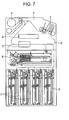
- FIG. 7 is an elevation view for explaining operation of recovery of paper moneys in the embodiment of the present invention;
- FIG. 8 is a flow chart for recovery of paper moneys in the embodiment of the present invention;
- FIG. 9 is a side view for explaining a condition in which paper moneys are stored into a loading and recovering bin;
- FIG. 10 is a side view for explaining a condition in which paper moneys are discharged from the loading and recovering bin;
- FIG. 11 is a top view illustrating the loading and recovering bin installed in the paper money receiving and paying apparatus;
- FIG. 12 is a side view illustrating a configuration of a travel regulating means;
- FIG. 13 is a view for explaining operation of storing paper moneys in the loading and recovering bin;
- FIG. 14 is a block diagram illustrating a control mechanism for storing and discharging paper moneys into and from the loading and recovering bin;
- FIG. 15 is a flow-chart for controlling the travel regulating means during-stacking of paper moneys;
- FIG. 16 is a flow chart for controlling the travel regulating means during stacking of paper moneys;
- FIG. 17 is a side view illustrating another example of an interference preventing means;
- FIG. 18 is a side view illustrating another example of the interference preventing means;
- FIG. 19 is a top view illustrating another friction reducing member;
- FIG. 20 is a plan view illustrating a configuration of a stacking assist means;
- FIG. 21 is a side view for explaining storing of paper moneys into the loading and recovering bin
- FIG. 22 is a side view for explaining discharging of paper moneys from the loading and recovering bin;
- FIG. 23 is a top view illustrating the loading and recovering bin installed in the paper money receiving and paying apparatus;
- FIG. 24 is a view for explaining operation of storing of paper moneys into the loading and recovering bin;
- FIG. 25 is a view for explaining operation of storing of paper moneys into the loading and recovering bin;
- FIG. 26 is a block diagram illustrating a control mechanism for storing and discharging paper moneys into and from the loading and recovering bin;
- FIGS. 27A to 27D are views for explaining operation of storing of paper moneys into the loading and recovering bin;
- FIG. 28 is a flow-chart for controlling the stacking assist means during stacking of paper moneys;
- FIG. 29 is a view for explaining operation of storing paper moneys into the loading and recovering bin; and
- FIG. 30 is a view illustrating another example of the loading and recovering bin.
- Referring to FIG. 1 which is a view illustrating an external appearance of an automatic teller machine in which the present invention is applied, the
automatic teller machine 101 in this embodiment, comprises, a card/check processing mechanism 102 for processing a traction card or a traction check owned by the customer, abanknote processing part 105 for processing a banknote, ahousing 104, and acustomer manipulation part 105 for displaying or inputting data required for traction. A paper money receiving and payingapparatus 1 is incorporated in thehousing 104. - FIG. 2 is a block diagram illustrating a control scheme of the present invention.
- Referring to FIG. 2, the card/
check processing mechanism 102, the banknote processing mechanism 103, thecustomer manipulation part 105 and the paper money receiving and payingapparatus 1 are connected to themain control part 106 through the intermediary of abus 110 so that they carry out required operation under the control of themain control part 106. In addition to the above, there are provided aninterface part 107, anoperator manipulation part 108 and anexternal memory device 109 which are also connected to thebus 110, for transmitting data therebetween. However, detailed description thereto will be omitted. Further, the above-mentioned mechanisms and components are powered by apower source part 111. - FIG. 3 is a view illustrating the configuration of the paper money receiving and paying apparatus mounted in the
automatic teller machine 101. - FIG. 4 is a view illustrating a control mechanism.
- Referring to FIGS. 3 and 4, the paper money receiving and paying
apparatus 1 comprises a receiving and payingport 2 for receiving and paying paper moneys, a papermoney determining part 3 for determining a denomination of a paper money, or determining whether a paper money is true or false, atemporary storage part 4 for temporarily storing received paper moneys until a transaction is completed, paper money bins for storing paper moneys, and a conveyingpath 5 connecting components in the paper money receiving and payingdevice 1 to one another, for conveying paper moneys. - The paper money bins are sorted in view of their roles, into for example, a receiving bin for storing therein paper moneys which are no more used as paper moneys to be paid, return bins for respectively storing denominations of paper moneys, and discharging them upon payment, a loading and recoverying bin for loading paper moneys into the return bins, and recovering paper moneys from the return bins.
- In this embodiment, a receiving
bin 6 is incorporated in a lower right part of the apparatus as shown in FIG. 3. Further, the remainder of the paper money bins is used asreturn bins 7. For example, they are for 50 Euro-dollar, 100 Euro-dollar and 200 Euro-dollar in the mentioned order as viewed from the left side of the figure. Further, the loading and recoveringbin 8 is located in the middle stage of the apparatus. The loading and recoveringbin 8 is adapted to store thereinto and discharge therefrom paper moneys to be handed in the paper money receiving and paying apparatus, in a mixed condition so as to be load or recover paper moneys into and from the return bins. - Further, the paper money receiving and paying
apparatus 1 incorporates a memory part DB in which correspondence between denominations and sizes of paper moneys is recorded. Thus, a size of a paper money can be found by determining a denomination thereof. Thecontrol part 9 is connected to themain control part 106 through the intermediary of thebus 110 so as to control the paper money receiving and payingapparatus 1 in accordance with an instruction from themain control part 106 and a detected state of the paper money receiving and payingapparatus 1, and the state of the paper money receiving and payingapparatus 1 is transmitted to themain control part 106 as required. - The loading of paper moneys can be carried out when the apparatus is replenished with paper moneys, for example, in the case of loading of paper moneys into the apparatus before operation of the
automatic teller machine 101, and in the case of loading of paper moneys when the number of loaded paper moneys becomes less during operation. - FIG. 5 is a view illustrating the configuration of the automatic teller machine, for explaining the loading operation of paper moneys in the embodiment of the present invention.
- Referring to FIG. 5, upon loading of paper moneys, paper moneys in the loading and recovering
bin 8 are fed onto the conveyingpath 5, and are conveyed in the direction of the arrow in the figure. At this stage, denominations and a number and conditions of paper moneys are determined by means of the papermoney determining part 3, and paper moneys which are not for payment are stored in the receivingbin 6, and paper moneys which are for payment are stored in the returningbins 7, being sorted into respective denomination groups. - FIG. 6 is a flow-chart for the above-mentioned loading of the paper moneys.
- Meanwhile, the recovery of paper moneys are carried out as required, in the case of recovery of paper moneys in the
automatic teller machine 101 after the operation is closed, or upon requirement of recovery of paper moneys in the apparatus when the number of loaded paper moneys becomes excessive during the operation. - FIG. 7 is a view illustrating a configuration of an automatic teller machine for explaining the operation during recovery of paper moneys in this embodiment.
- Referring to FIG. 7, during recovery of paper moneys, paper moneys in the
return bins 7 are fed onto the conveyingpath 5, and are conveyed in the direction of the arrow. At this time, denominations and numbers of paper moneys are determined by way of the papermoney determining part 3, and then the paper moneys are stored in the loading and recoveringbin 8. It is noted that, in this embodiment, the receivingbin 6 is adapted to be directly removed in order to recover paper moneys therein. - FIG. 8 shows a flow-chart for the recovery operation.
- The number of paper moneys in the apparatus can be confirmed by carrying out the recovery operation and the loading operation.
- FIG. 9 is a side view illustrating a state in which paper moneys are stored in the loading and recovering
bin 8. - FIG. 10 is a side view illustrating a sate in which paper moneys are discharged from the loading and recovering
bin 8. - FIG. 11 is a top view illustrating the configuration of the loading and recovering
bin 8 mounted in the paper money receiving and payingapparatus 1. - Referring to FIGS. 9, 10 and 11, the loading and recovering
bin 8 is a horizontal paper money bin in which paper moneys are horizontally stored in a standing posture, and is adapted to store and separate paper moneys having different sizes. - A paper money introducing and discharging mechanism is composed of
stack feed rollers 801, pick-uprollers 811, drivenbackup rollers 802 andgate rollers 803 which are rotated in a storing direction but is not rotated in a pay-out direction, andbrush rollers 804 which are coaxial-with thegate rollers 803 and to which flexible push-in members are radially arranged, and a separating and stackingguide 805 whose position is changed between separation and stacking. - The
stack feed rollers 801 are driven for rotation with the use of a drive source and gears which are not shown, so as to feed paper moneys to be stored, and feed paper moneys to be discharged onto the conveyingpath 5. Thebackup rollers 802 are rotated being driven by thestack feed rollers 801 so as to pinch a paper money between itself and thestack feed roller 801 in order to convey the paper money. Thegate roller 803 are rotated being driven by the stack feed rollers 80 when paper moneys are stored but is not rotated when they are discharged. - That is, when paper moneys are separated and paid out by the pick-up
rollers 811 and the stack-feed rollers 801, a paper money adjacent to a paper money to be discharged makes contacts with thegate rollers 803 in order to prevent the paper money from being paid out following the paper money to be discharged. - The
stack feed rollers 801 and thegate rollers 803 define an introduction and discharge port communicated with the stacking space. That is, after the paper money introduced from the outside is released from the pinch between thestack feed rollers 801 and thegate rollers 803, it falls in a unrestrained condition, and is therefore introduced into the stacking space. - It is noted the
brush rotor 804 has the flexible push-in members only for a substantially semicircular circumference thereof in order to carry out discharge operation of paper moneys. When paper moneys are stored, it is rotated in the storing direction of paper moneys, the paper moneys stacked in the stacking space are scraped into the storage space by the flexible push-in members which are radially arranged. When the paper moneys are discharged, thebrush rollers 804 come to a stop at a position at which no flexible push-in members appear in the stacking space. Thus, paper moneys can be discharged without interference with the flexible push-in members. - Further, the pick-up
rollers 811 are driven in synchronization with the stack-feed rollers 801, and further, thebrush rollers 804 are adapted to be rotated, reverse to the rotation of thestack feed roller 801 so as to aim at commonly using the drive source. - It is noted that the
brush rollers 804 is coupled to thestack feed rollers 801 through the intermediary of a one-way clutch, and accordingly, thebrush rollers 804 are not rotated upon discharge of paper moneys. - Further, the one-way clutch is the one which is rotated in one direction but is not in a reverse direction, that is, it is rotated clockwise, but is not counterclockwise.
- The separating and stacking
guide 805 has a surface on the stacking space side, which serves as a paper money guide surface for guiding a paper money when it is stored or discharged. Upon storing of a paper money, the paper money guide surface is located at a position which is along an extension from the introduction and discharge opening of the introducing and discharging mechanism in the traveling direction of paper moneys. Upon discharging of paper moneys, the paper money guide surface is retraced up to a position where thepickup rollers 811 are exposed. - The storage space is defined being surrounded by the
floor surface 808, afloor surface belt 807 which is suspended so as to support the lower ends of paper moneys at a surface above thefloor surface 808, the push-plate 806, the separating and stackingguide 805, thetop plate 810 and side walls 913. - The side walls 913 are mounted at positions which can be set in accordance with a size of a paper money. The width between the
side walls 813 is appropriately set, being adjusted to a value which is larger that a widthwise dimension of a paper money by 2 to 10 mm. Further, the distance between thefloor surface 808 and thetop plate 810 is set to a value which is larger than the heightwise length of a paper money having a largest size. Thus, paper moneys having a largest size to be handled in the paper money receiving and paying apparatus can be stored. - A transmission sensor is composed of a
light emitting element 888 a and alight receiving element 888 b. When a paper money is present in the vicinity of the introduction and discharge opening, the paper money blocks a light beam so that the presence of the paper money in the vicinity of the introduction and discharge opening can be known. - Four Blade Mechanism
- In this embodiment, the travel regulating means 891 for restraining an excessive travel of a paper money to be stacked is provided above the separating and stacking
guide 805. - FIG. 12 is a view illustrating a donfiguration of the travel regulating means 891.
- Referring to FIG. 12, the travel regulating means 891 incorporates, at each distal end thereof, a rolling
member 891a as a friction reducing member for reducing friction with respect to a paper money. - It is noted that there may be used, as another example of the friction reducing member, a spherical or rhombus part at the distal end of the travel regulating means 891, or a spherical or rhombus movable element, as shown in FIG. 19, instead of the rolling
member 891 a. - The stacking space is defined by the separating and stacking
guide 805, thefloor surface 808 and the travel regulating means 891, and paper moneys introduced from the outside are stacked in this stacking space. - It is noted, as shown in FIG. 9, that the
floor surface belt 807 and thefloor surface 808 are inclined so as to serve as the interference preventing means, and accordingly, theside walls 813, a rail for thepush plate 806 and thetop plate 810 are inclined. Thus, paper moneys are prevented from being caught to the separating and stackingguide 805, thereby it is possible to ensure the stacking space. - It is noted that the loading and recovering
bin 8 may be installed, being inclined in its entirety in the paper money receiving and payingapparatus 1 as another means for attaining the above-mentioned object. - The travel regulating means 891 has a role of restraining a paper money from excessively traveling upward when it is stacked in the stacking space.
- It is noted, as shown in FIG. 11, a plurality of travel regulating means 891 are provided widthwise of a paper money so that the upper ends of the stacked paper moneys are regulated at a plurality of positions.
- Further, in order to prevent a paper money from entering thereabove, being accompanied with the rotation of the travel regulating means 891, as shown in FIG. 9, a paper money entrance preventing means having a shape for catching a paper money may be provided above the stacking space.
- Operation of Four Blades
- Next, explanation will be made of the operation in such a case that paper moneys having different sizes are stored, being mixed together, in the loading and recovering
bin 8. - FIG. 14 is a schematic view which shows control of storing and discharging of paper moneys into and from the loading and discharging bin.
- Referring to FIG. 14, the
control part 9 runs under control drive parts and sensors and the like in the loading and recoveringbin 8. Further, a paper money size detecting means composed of the papermoney determining part 3 for determining a denomination of a paper money, and the memory part DB having the data base for correspondence between denominations and sizes of paper moneys, recognizes a size of a paper money passing through the papermoney determining part 3, and delivers at once data thereof to the control part. At this stage, data corresponding to an order number on conveyance thereof is also transmitted to thecontrol part 9. - FIG. 13 is a view for explaining the operation for storing paper moneys into the loading and recovering bin in this embodiment.
- Referring to FIG. 13, a paper money is passed through the paper
money determining part 3, and thereafter, it is conveyed to the loading and recoveringbin 8. Thecontrol part 9 drives amotor 801m for the stack feed rollers so as to rotate thestack feed roller 801 and thegate roller 803, and accordingly, thepaper money 1000 is pinched therebetween so as to be conveyed into the loading and recoveringbin 8. At this time, thepaper money 1000 is conveyed, being maintained in its standing posture along the paper money guide surface of the separating and stackingguide 805. - Further, after it is released from the pinching between the
stack feed rollers 801 and thegate rollers 803, the leading end of thepaper money 1000 impinges upon a projection (the rollingmember 891 a) of the travel regulating means 891. - It is noted that the
control part 9 drives amotor 891 for the travel regulating means in accordance with a paper money conveying time from the papermoney determining part 3 to the loading and separatingbin 8 when data concerning a paper money to be introduced into the loading and recoveringbin 8 is delivered to thecontrol part 9, and accordingly, the travel regulating means 891 is rotated counterclockwise under control as viewed in FIG. 13 so that the distance from thefloor surface 808 to the protrusion of the travel regulating means 891 becomes equal to a length of any of paper moneys to be stacked, in the traveling direction. - It is noted that the travel regulating means 891 is controlled so as to be rotated, in principle, by a portion of one protrusion for one paper money. Thus, the leading end of the
paper money 1000 is regulated in order to prevent excessive travel thereof, and accordingly, paper money can be stacked with their leading ends are aligned with one another on thefloor surface 808. - Further, the protrusions of the travel regulating means 891 are rotated one by one for every paper money, and accordingly, paper moneys having different sizes can be successively stacked.
- It is noted as shown in FIG. 13 that a paper money detecting means 892 for detecting a paper money on running may be arranged in the vicinity of the back-up
roller 802 so as to rotate, under control, the travel regulating means 891 for every paper money to be stacked with a timing of passing of the paper money. - FIG. 15 is a view which shows a control flow-chart for storage operation of the travel regulating means 891 in this embodiment.
- FIG. 16 is a view which shows a control flow chart for storage operation of the travel regulating means 891 in this case.
- It is noted that the lower ends of paper moneys stacked in the stacking space are restrained by the
brush rollers 804 so as to prevent a next paper money from impinging upon them. Meanwhile when a number of paper moneys in the vicinity of the stacking space is increased so that a time by which the transmission sensor 888 is shielded is longer than a predetermined time, thecontrol part 9 drives thedrive motor 806m for the push-plate so as to displace the push-plate 806 in a direction in which the storage space is enlarged. - Separating Operation of Four Blades
- Next, explanation will be made of operation in the case of discharging paper moneys from the loading and recovering
bin 8. When paper moneys are discharged from the loading and recoveringbin 8, as shown in FIG. 10, thedrive motor 806m for the push-plate is driven so as to displace the push-plates 809 toward the separating and stackingguide 805 so as to press stored paper moneys against the separating and stackingguide 805. Simultaneously, the separating and stackingguide 805 and the travel regulating means 891 are retracted so as to expose the pick-uprollers 811. Further, by rotating the pick-uprollers 811, stored paper moneys are separated one by one while they are discharged outside from the loading and recoveringbin 8. - It is noted that stable discharge of paper moneys can be made since the lower ends of paper moneys are stacked being aligned with one another along the
floor surface 808 upon stacking of paper moneys, as mentioned above. - Thus, according to the present invention, paper moneys having different sizes can be stored in one and the same loading and recovering bin, being mixed with one another.
- FIG. 17 is a view for illustrating the interference preventing means in another embodiment.
- FIG. 18 is a view for illustrating the interference preventing means in the other embodiment.
- Referring to FIGS. 17 and 18, although it has been explained that the
floor surface belt 807 and thefloor surface 808 are inclined so as to serve as the interference preventing means, a push-plate 806 a incorporating a push-plate inclining spring 806 s may be used as the interference preventing means. In this case, as shown in FIG. 17, the push-plate 806 a is inclined by a force of the push-plate inclining spring 806 s so as to incline the stored paper moneys in the storage space, and accordingly, the stored paper moneys are prevented from being caught by the separating and stackingguide 805, thereby it is possible to ensure the stacking space. Meanwhile, as shown in FIG. 18, as the push-plate 806 a is displaced toward the separating and stackingguide 805 during separation of paper moneys, the postures of the stored paper moneys and the push-plate 806 a are changed in a direction along the separating and stackingguide 805, due to a reaction force of the separating and stackingguide 805, and accordingly, stable separation can be carried out. - FIG. 19 is a view for explaining the friction reducing means in another embodiment.
- Single Blade Mechanism
- It is noted that a stacking assist means 812 having both functions of the travel regulating means and the interference preventing means may be used as shown in FIG. 20 which will be hereinbelow explained, instead of the travel regulating means 891 shown in FIG. 12. The stacking assist means 812 is composed of a
stopper part 812 a capable of executing the function of the travel regulating means and a papermoney supporting part 812 b capable of executing the function of the interference preventing means. - The stopper part 612 a has a role of regulating an upward travel of a paper money when paper moneys are stacked in the stacking space. The paper
money supporting part 812 b defines a boundary between the stacking space and the storage space, and has a role of supporting the paper moneys stored in the storage space. The distance between the distal end of the paper money supporting part 512 b to thefloor surface 808 is shorter than the length of a paper money having a smallest size in the traveling direction, which is to be handled in the paper money receiving and payingapparatus 1, that is, it is shorter than the height of the paper money which is stored in its standing posture. With this configuration, a paper money introduced in its standing posture is prevented from turning over, and as well, paper moneys having stored in the storage space from entering into the stacking space. - Although the stacking assist means shown in FIG. 20 has only one
paper support part 812 b, it may have two papermoney support parts 812 b. - It is noted that paper moneys are not held between one of the paper
money supporting members 812 b and the other one of them, but the paper moneys are stacked in the stacking space defined by thepaper support parts 812 b, the stopper part 612 a, the separating and stackingguide 805 and thefloor surface 808. - FIG. 23 is a top view illustrating the configuration of the loading and recovering
bin 8 incorporating the stacking assist means 812. Further, FIG. 21 is a side view which shows such a state that paper moneys are stored in the loading and recoveringbin 8 while FIG. 22 is a side view which shows such a state that paper moneys are discharged from the loading and recoveringbin 8. - It is noted, as shown in FIG. 24, that the separating and stacking
guide 805 incorporates a stacking space volume detecting means 890 which is normally projected into the stacking space by a spring which is not shown, but which is turned down toward the separating and stackingguide 805 by paper moneys when the paper moneys occupies the stacking space. Thus, occupation of the stacking space by paper moneys can be detected. - Stacking Operation of Single Blade
- Next, explanation will be made of the operation of the loading and recovering
bin 8 in the case of storing paper moneys. In the case of the storing paper money in the loading and recoveringbin 8, recovery or precisely investigation of paper moneys are caried out. That is, paper moneys are successively conveyed to the loading and recoveringbin 8 for each of thereturn bins 7 for respectively storing different denominations of paper moneys, in other words, paper moneys having one and the same size are conveyed in a bundle to the associated loading and recoveringbin 8. - As shown in FIG. 26, the
control part 9 runs drive parts, sensors and like in the loading and recoveringbin 8. Further, the paper money size detecting means which is composed of the papermoney determining part 3 for determining a denomination of a paper money, and the memory part DB having a data base in which denominations and sizes of paper money are related to one another recognizes a size-of a paper money passing through the papermoney determining part 3, and transmits data thereof to thecontrol part 9. - When the data of a size of a paper money to be introduced into the loading and recovering
bin 8 is transmitted to thecontrol part 9, thecontrol part 9 drives adrive motor 812m for the stacking assist means 812 which is therefore rotated up to a position where the distance from thefloor surface 808 to thestopper part 812a becomes equal to the length of the paper money to be introduced in the traveling direction, and is then fixed. It is noted that FIG. 24 shows such a state that the size of a paper money to be introduced is relatively small, and FIG. 25 shows such a state that the size of a paper money to be introduced is relatively large. Further, it is noted, as shown in FIG. 29, that the upper part of the separating and stackingguide 805 may be formed in a circular shape so as to increase the upper limit of the size of paper moneys which are allowed to be stacked. - Next, the
drive motor 801m for the stack feed rollers is driven so as to rotate thestack feed rollers 801 and the gate rollers 503 in order to clamp and convey apaper money 1000 into the loading and recoveringbin 8. At this time, thepaper money 1000 is conveyed being held in its standing posture along the separating and stackingguide 805. - Further, when the clamp between the stack feed rollers and the
gate rollers 803 is released, the leading end of thepaper money 1000 impinges upon thestopper part 812 of the stacking assist means 812. That is, by regulating the leading end of thepaper money 1000, excessive traveling is prevented, and accordingly, paper moneys can be stacked with their trailing ends aligned along thefloor surface 808. - When stacking of paper moneys as mentioned above is continued so that the degree of occupation of the stacking space by the stacked paper moneys becomes larger, which is detected by the stacking space volume detecting means 890, as shown in FIG. 27, the
control part 9 drives thedrive motor 812m for the stacking assist means 812 which is therefore rotated. Thus, a paper moneys existing between the separating and stackingguide 805 and the papermoney supporting part 812 b are shifted into the storage space, and accordingly, no paper moneys are present in the stacking space. It is noted that the conveyance of the paper moneys to the loading and recoveringbin 8 is desirably interrupted when the stacking assist means 812 is being rotated. - After the storage of paper moneys having a certain size has been completed through the above-mentioned procedure, the position of the stacking assist means 812 is changed in accordance with a size of paper moneys to be then stored, the storage thereof is carried out. With the repetitions of these steps, paper moneys stored in the
return bins 7 can be stored in the single loading and recoveringbin 8 by a number which is as large as that allowed by the capacity thereof. FIG. 28 shows a control flow-chart for the storage operation of the stacking assist means 812 in this embodiment. - It is noted the configurations of the
brush rollers 804 and thepush plate 806, and the control thereof are the same as those stated above. However, the driving timing of the push-plate 806 may be synchronized with the rotating timing of the above-mentioned stacking assist means 512. - Separating Operation of Single Blade
- Next, explanation will be made of the operation in the case of discharging paper moneys from the loading and recovering
bin 8. When paper moneys are discharged from the loading and recoveringbin 8, as shown in FIG. 22, thedrive motor 806m for the push-plate is driven so as to displace the push-plate 805 toward the separating and stackingguide 805 in order to press stored paper moneys against the separating and stackingguide 805. Simultaneously, the separating and stackingguide 805 and the stacking assist means 812 are retracted from the storage space so as to expose the pick-uprollers 811 which are then rotated so as to discharge stored paper moneys, being separated one by one, outside of the loading and recoveringbin 8. It is noted that the paper moneys can be stably discharged since the paper moneys are stored with their lower ends are aligned along thefloor surface 808 during stacking thereof, as stated above. - With the use of the loading and recovering
bin 8 stated above, it is possible to provide an automatic teller machine capable of loading and recovering paper moneys having different sizes into the paper money receiving and paying apparatus. - It is noted that the
temporary storage part 4 for temporarily storing received paper moneys until the transaction thereof is completed, is the one which stacks, at first, paper moneys introduced in the receiving and payingport 2 by a user, and accordingly, it has a function of stacking paper moneys having different sizes, similar to the loading and recoveringbin 8. Thus, with the application of the present invention to thetemporary storage part 4, it is possible to provide an automatic teller machine which can receive and pay paper moneys having different sizes. - Further, in this embodiment, although explanation has been made of such an example that the receiving bin is used for receiving reject paper moneys, and the return bins are used to receive different denominations of paper moneys, respectively, the loading and recovering
bin 8 in this embodiment may be used as the receiving bin or the return bin. - Further, although explanation has been made of the paper money bin of a horizontal type in which paper moneys are stored in a standing posture, the present invention can be applied to a paper money bin of a vertical type in which paper moneys are horizontally stacked, as shown in FIG. 30. It is noted as shown in FIG. 30 that a push-
plate 806 b may be inclines so as to align the left ends of paper moneys along thefloor surface 808 side under the gravitation. In this case, although the direction of inclination of the push-plate 806 b is different from that of the push-plate 806 a as stated above, the function thereof is the same as that of the latter. - The other components shown in FIG. 30 have functions similar to those as stated above. Thus, even in the loading and recovering
bin 8 of a horizontal type, the stacking of paper moneys which are aligned along thefloor surface 808 can be made with the provision of the travel regulating means 891 for restraining excessive travel, thereby it is also possible to stably separate paper moneys. - Further, the apparatus according to the present invention can be applied not only to paper moneys but also to all paper sheets.
- With the use of the present invention, there can be provided a paper money receiving and paying apparatus and an automatic teller machine which can stack and separate paper moneys having different sizes in a mixed condition.
- It should be further understood by those skilled in the art that although the foregoing description has been made on embodiments of the invention, the invention is not limited thereto and various changes and modifications may be made without departing from the spirit of the invention and the scope of the appended claims.
Claims (20)
1. A paper money receiving and paying apparatus characterized by a stacking and separating device for stacking and separating paper moneys, a paper money size detecting means for detecting sizes of paper moneys stacked in the stacking and separating device, and a travel regulating means for regulating a travel of a paper money in the stacking and separating device, and a control part for controlling the travel regulating means in accordance with a size of a paper money.
2. A paper money receiving and paying apparatus as set forth in claim 1 , characterized in that the travel regulating means causes a leading end of a paper money to impinge thereupon, and a position of the travel regulating means is changed in accordance with a size of the paper money.
3. A paper money receiving and paying apparatus as set forth in claim 1 , characterized in that the travel regulating means is adapted to rotate so as to change the position where the leading end of a paper money impinges thereupon.
4. A paper money receiving and paying apparatus as set forth in claim 1 , characterized in that an external shape of the travel regulating means is arcuated in a part thereof, or in its entirety.
5. A paper money receiving and paying apparatus as set forth in claim 1 , further characterized by an interference preventing means for preventing paper moneys after accumulation thereof from entering into a space for accumulating paper moneys.
6. A paper money receiving and paying apparatus as set forth in claim 5 , characterized in that the stacking and separating device includes a storage space where accumulated paper moneys are stored, and the interference preventing means is an inclined floor surface in the storage space.
7. A paper money receiving and paying apparatus as set forth in claim 5 , characterized in that the stacking and separating device comprises a push-plate for retaining stacked paper moneys, and the interference preventing means is the push-plate which defines an inclined surface upon stacked of paper moneys.
8. A paper money receiving and paying apparatus as set forth in claim 5 , wherein the travel regulating means and the interference preventing means are integrally incorporated with each other.
9. A paper money receiving and paying apparatus as set forth in claim 1 or 5, characterized in that the travel regulating means and the interference preventing means can be retracted so as to prevent interference with stacked paper moneys.
10. A paper money receiving and paying apparatus as set forth in claim 1 or 5, characterized in that a friction reducing member is incorporated in either or both of the travel regulating means and the interference preventing means.
11. A paper money receiving and paying apparatus as set forth in claim 1 or 5, characterized in that there are provided either or both of the travel regulating means and the interference preventing means in a plural number.
12. A paper money receiving and paying apparatus as set forth in claim 1 , characterized in that the travel regulating means includes a paper money enterance preventing means for preventing stacked paper moneys from being caught.
13. A paper money receiving and paying apparatus as set forth in claim 1 , characterized in that the stacking and separating device incorporates a separating and accumulating guide for guiding stacked paper money which has been introduced, and the separating and stacking guide has an end part which is curved.
14. A paper money receiving and paying apparatus as set forth in claim 1 , characterized in that the paper money size detecting means comprises a paper money determining part for determining a denomination of a paper money, and a memory part incorporating a data base in which denominations and sizes of paper moneys are assigned to each other.
15. A paper money receiving and paying apparatus as set forth in claim 1 , further characterized by a paper money detecting means for detecting a paper money conveyed to the stacking and separating means, and the travel regulating means is controlled through the detection of a paper money by the paper money detecting means.
16. A paper money receiving and paying apparatus as set forth in claim 1 , further characterized by a stacking space volume detecting means for detecting an occupying value of stacked paper moneys which occupy a space for stacking paper moneys within the stacking and separating device, and the travel regulating means is controlled in accordance with a result of detection by the stacking space volume detecting means.
17. A paper money receiving and paying apparatus as set forth in claim 1 , characterized in that the stacking and separating device stacks paper moneys in a standing posture.
18. A paper money receiving and paying apparatus as set forth in any one of claims 1 to 17 , further characterized by a receiving and paying port for carrying out either or both of separation of paper moneys introduced by a user and stacking of paper moneys to be paid to a user, a paper money determining means for determining a denomination of a paper money, a temporary storage bin for temporarily storing paper moneys, either or both of a receiving bin for storing therein paper moneys which are inappropriate for payment and a return bin for respectively storing therein and discharging different denominations of paper moneys therefrom, and a conveying path connecting the paper money determining part, the temporary storage bin and the bins to one another, for conveying paper moneys, and characterized in that the stacking and separating device is the temporary storage bin.
19. A paper money receiving and paying apparatus as set forth in any one of claims 1 to 17 , further characterized by a receiving and paying port for carrying out either or both of separation of paper moneys introduced by a user and stacking of paper moneys to be paid to a user, a paper money determining means for determining a denomination of a paper money, a temporary storage bin for temporarily storing paper moneys, return bins for respectively storing therein and discharging therefrom different denominations of paper moneys, a loading and recovering bin for charging paper moneys to and from the return bins, and a conveying path connecting the paper money determining means, the temporary storage bin and the bins to one another, for conveying paper moneys, and characterized in that the stacking and separating device is either or both of the temporary storage bin and the loading and recovering and discharging bin.
20. An automatic teller machine comprising a paper money receiving and paying apparatus as stated in any one of claims 1 to 19 .
Applications Claiming Priority (2)
| Application Number | Priority Date | Filing Date | Title |
|---|---|---|---|
| JP2003-172759 | 2003-06-18 | ||
| JP2003172759A JP2005010967A (en) | 2003-06-18 | 2003-06-18 | Bill depositing and dispensing device and automatic teller machine |
Publications (1)
| Publication Number | Publication Date |
|---|---|
| US20040256784A1 true US20040256784A1 (en) | 2004-12-23 |
Family
ID=33410940
Family Applications (1)
| Application Number | Title | Priority Date | Filing Date |
|---|---|---|---|
| US10/772,277 Abandoned US20040256784A1 (en) | 2003-06-18 | 2004-02-06 | Paper money receiving and paying apparatus and automatic teller machine |
Country Status (4)
| Country | Link |
|---|---|
| US (1) | US20040256784A1 (en) |
| EP (1) | EP1489563A1 (en) |
| JP (1) | JP2005010967A (en) |
| CN (1) | CN100367318C (en) |
Cited By (8)
| Publication number | Priority date | Publication date | Assignee | Title |
|---|---|---|---|---|
| US20060032913A1 (en) * | 2003-02-10 | 2006-02-16 | Akira Nomiyama | Banknote receipt and payout apparatus |
| US20090033020A1 (en) * | 2007-08-02 | 2009-02-05 | Ncr Corporation | Presenting misaligned stacks of media |
| CN102800160A (en) * | 2011-05-26 | 2012-11-28 | 富士通先端科技株式会社 | Paper bill depositing/dispensing apparatus |
| CN103150848A (en) * | 2012-08-21 | 2013-06-12 | 珠海市新域智能科技有限公司 | Banknote transfer passage, self-service terminal capable of being provided with multiple banknote boxes, and comprehensive self-service payment and changing service terminal |
| CN107481452A (en) * | 2017-09-30 | 2017-12-15 | 深圳怡化电脑股份有限公司 | The withdrawing device of self-service device and self-service device |
| RU2677599C2 (en) * | 2016-05-17 | 2019-01-17 | Атек Ап Ко., Лтд. | Financial device and method for controlling same |
| EP3441340A1 (en) * | 2008-04-15 | 2019-02-13 | Wincor Nixdorf International GmbH | Single sheet handling device for inputting and for dispensing of rectangular individual sheets, in particular banknotes, into or out of a container |
| US10297098B2 (en) | 2015-10-28 | 2019-05-21 | Fujitsu Frontech Limited | Paper sheet storage apparatus and storing method of paper sheet storage apparatus |
Families Citing this family (16)
| Publication number | Priority date | Publication date | Assignee | Title |
|---|---|---|---|---|
| EP2256700A1 (en) | 2005-07-27 | 2010-12-01 | MEI, Inc. | Banknote handling |
| JP4770505B2 (en) * | 2006-02-17 | 2011-09-14 | 沖電気工業株式会社 | Paper sheet take-out mechanism |
| JP2007323130A (en) * | 2006-05-30 | 2007-12-13 | Laurel Seiki Kk | Bill processor |
| JP2008063025A (en) * | 2006-09-05 | 2008-03-21 | Hitachi Omron Terminal Solutions Corp | Paper sheet handling device |
| JP4804504B2 (en) | 2008-05-09 | 2011-11-02 | 日立オムロンターミナルソリューションズ株式会社 | Bill deposit / withdrawal apparatus, automatic cash transaction apparatus, and bill accumulation method |
| JP5463748B2 (en) * | 2009-06-16 | 2014-04-09 | 沖電気工業株式会社 | Media processing device |
| US8573405B2 (en) * | 2009-08-31 | 2013-11-05 | Ncr Corporation | Media depository |
| JP5216808B2 (en) * | 2010-05-20 | 2013-06-19 | 日立オムロンターミナルソリューションズ株式会社 | Paper sheet management apparatus and paper sheet management method |
| DE102010036577A1 (en) * | 2010-07-22 | 2012-01-26 | Wincor Nixdorf International Gmbh | Money deposit/withdrawal device e.g. automated teller machine (ATM) has filling and removal unit that is connected to value note transport container for filling and removing value note with respect to value note container |
| JP5935510B2 (en) * | 2012-05-28 | 2016-06-15 | 沖電気工業株式会社 | Automatic transaction equipment |
| CN105788076B (en) * | 2016-02-06 | 2018-12-07 | 北京银丰新融科技开发有限公司 | A kind of card aggregation apparatus and its signal light control application method applied to finance self-help terminal |
| CN108629888B (en) * | 2017-03-17 | 2019-11-12 | 山东新北洋信息技术股份有限公司 | The control method and control device of bank note aggregation device |
| CN107331038A (en) * | 2017-08-14 | 2017-11-07 | 昆山古鳌电子机械有限公司 | Bill accomodating device in a kind of ATM |
| CN109712308B (en) * | 2017-10-20 | 2021-02-19 | 山东新北洋信息技术股份有限公司 | Paper money collecting and separating device and cash recycling machine |
| WO2019136701A1 (en) * | 2018-01-12 | 2019-07-18 | 深圳市倍量科技有限公司 | Paper bill storage device |
| CN110288759B (en) * | 2018-03-13 | 2022-01-25 | 山东新北洋信息技术股份有限公司 | Paper money collecting device, limiting mechanism and cash recycling equipment |
Citations (9)
| Publication number | Priority date | Publication date | Assignee | Title |
|---|---|---|---|---|
| US4980543A (en) * | 1983-01-26 | 1990-12-25 | Tokyo Shibaura Denki Kabushiki Kaisha | Multiple denominator bank note depositor/dispenser with automatic loading to and from storage section |
| US5476256A (en) * | 1994-07-29 | 1995-12-19 | Xerox Corporation | Disk stacker including passive sheet registration assist system |
| US5803227A (en) * | 1995-06-06 | 1998-09-08 | International Game Technology | Bill stacker |
| US6109522A (en) * | 1997-11-28 | 2000-08-29 | Diebold, Incorporated | Automated banking machine with self auditing capabilities and system |
| US6331000B1 (en) * | 1998-09-17 | 2001-12-18 | Diebold, Incorporated | Currency recycling system and method for automated banking machine |
| US20020170956A1 (en) * | 1998-12-08 | 2002-11-21 | Riichi Katou | Bill deposit/withdrawal machine for depositing/withdrawing bills |
| US20030127509A1 (en) * | 2002-01-07 | 2003-07-10 | Akira Nomiyama | Bill receiving/paying device and automated cash transaction apparatus |
| US20040003980A1 (en) * | 2002-06-13 | 2004-01-08 | Hallowell Curtis W. | Currency processing and strapping systems and methods |
| US20040016621A1 (en) * | 2000-02-11 | 2004-01-29 | Jenrick Charles P. | Currency handling system having multiple output receptacles |
Family Cites Families (1)
| Publication number | Priority date | Publication date | Assignee | Title |
|---|---|---|---|---|
| GB9823337D0 (en) * | 1998-10-23 | 1998-12-23 | Rue De Int Ltd | Sheet stacking apparatus |
-
2003
- 2003-06-18 JP JP2003172759A patent/JP2005010967A/en active Pending
-
2004
- 2004-02-06 US US10/772,277 patent/US20040256784A1/en not_active Abandoned
- 2004-02-09 CN CNB2004100048384A patent/CN100367318C/en not_active Expired - Fee Related
- 2004-02-09 EP EP04002794A patent/EP1489563A1/en not_active Withdrawn
Patent Citations (10)
| Publication number | Priority date | Publication date | Assignee | Title |
|---|---|---|---|---|
| US4980543A (en) * | 1983-01-26 | 1990-12-25 | Tokyo Shibaura Denki Kabushiki Kaisha | Multiple denominator bank note depositor/dispenser with automatic loading to and from storage section |
| US5476256A (en) * | 1994-07-29 | 1995-12-19 | Xerox Corporation | Disk stacker including passive sheet registration assist system |
| US5803227A (en) * | 1995-06-06 | 1998-09-08 | International Game Technology | Bill stacker |
| US6109522A (en) * | 1997-11-28 | 2000-08-29 | Diebold, Incorporated | Automated banking machine with self auditing capabilities and system |
| US6331000B1 (en) * | 1998-09-17 | 2001-12-18 | Diebold, Incorporated | Currency recycling system and method for automated banking machine |
| US20020170956A1 (en) * | 1998-12-08 | 2002-11-21 | Riichi Katou | Bill deposit/withdrawal machine for depositing/withdrawing bills |
| US20040016621A1 (en) * | 2000-02-11 | 2004-01-29 | Jenrick Charles P. | Currency handling system having multiple output receptacles |
| US20030127509A1 (en) * | 2002-01-07 | 2003-07-10 | Akira Nomiyama | Bill receiving/paying device and automated cash transaction apparatus |
| US6889897B2 (en) * | 2002-01-07 | 2005-05-10 | Hitachi, Ltd. | Bill receiving/paying device and automated cash transaction apparatus |
| US20040003980A1 (en) * | 2002-06-13 | 2004-01-08 | Hallowell Curtis W. | Currency processing and strapping systems and methods |
Cited By (16)
| Publication number | Priority date | Publication date | Assignee | Title |
|---|---|---|---|---|
| US20060032913A1 (en) * | 2003-02-10 | 2006-02-16 | Akira Nomiyama | Banknote receipt and payout apparatus |
| US20070187486A1 (en) * | 2003-02-10 | 2007-08-16 | Akira Nomiyama | Banknote receipt and payout apparatus |
| US7428983B2 (en) * | 2003-02-10 | 2008-09-30 | Hitachi-Omron Terminal Solutions Corp. | Banknote receipt and payout apparatus |
| US7431205B2 (en) | 2003-02-10 | 2008-10-07 | Hitachi-Omron Terminal Solutions Corp. | Banknote receipt and payout apparatus |
| US20090033020A1 (en) * | 2007-08-02 | 2009-02-05 | Ncr Corporation | Presenting misaligned stacks of media |
| US7721952B2 (en) * | 2007-08-02 | 2010-05-25 | Ncr Corporation | Presenting misaligned stacks of media |
| EP3441336A1 (en) * | 2008-04-15 | 2019-02-13 | Wincor Nixdorf International GmbH | Single sheet handling device for inputting and for dispensing of rectangular individual sheets, in particular banknotes, into or out of a container |
| EP3441340A1 (en) * | 2008-04-15 | 2019-02-13 | Wincor Nixdorf International GmbH | Single sheet handling device for inputting and for dispensing of rectangular individual sheets, in particular banknotes, into or out of a container |
| EP3441337A1 (en) * | 2008-04-15 | 2019-02-13 | Wincor Nixdorf International GmbH | Single sheet handling device for inputting and for dispensing of rectangular individual sheets, in particular banknotes, into or out of a container |
| CN102800160A (en) * | 2011-05-26 | 2012-11-28 | 富士通先端科技株式会社 | Paper bill depositing/dispensing apparatus |
| CN103150848A (en) * | 2012-08-21 | 2013-06-12 | 珠海市新域智能科技有限公司 | Banknote transfer passage, self-service terminal capable of being provided with multiple banknote boxes, and comprehensive self-service payment and changing service terminal |
| CN103150849A (en) * | 2012-08-21 | 2013-06-12 | 珠海市新域智能科技有限公司 | Banknote transfer passage, self-service terminal capable of being provided with multiple banknote boxes, and old banknote self-service exchange service terminal |
| US10297098B2 (en) | 2015-10-28 | 2019-05-21 | Fujitsu Frontech Limited | Paper sheet storage apparatus and storing method of paper sheet storage apparatus |
| RU2677599C2 (en) * | 2016-05-17 | 2019-01-17 | Атек Ап Ко., Лтд. | Financial device and method for controlling same |
| US10233049B2 (en) | 2016-05-17 | 2019-03-19 | Lg Cns Co., Ltd | Financial device and method for controlling the same |
| CN107481452A (en) * | 2017-09-30 | 2017-12-15 | 深圳怡化电脑股份有限公司 | The withdrawing device of self-service device and self-service device |
Also Published As
| Publication number | Publication date |
|---|---|
| EP1489563A1 (en) | 2004-12-22 |
| CN100367318C (en) | 2008-02-06 |
| CN1573825A (en) | 2005-02-02 |
| JP2005010967A (en) | 2005-01-13 |
Similar Documents
| Publication | Publication Date | Title |
|---|---|---|
| US20040256784A1 (en) | Paper money receiving and paying apparatus and automatic teller machine | |
| US6889897B2 (en) | Bill receiving/paying device and automated cash transaction apparatus | |
| JP3977982B2 (en) | Banknote storage and release box and banknote deposit and withdrawal machine | |
| US7428983B2 (en) | Banknote receipt and payout apparatus | |
| CN103106732B (en) | Paper currency handling device | |
| JP2000187752A (en) | Paper money receiving/paying device | |
| JP2007279907A (en) | Coin depositing and dispensing machine | |
| KR910001241B1 (en) | Apparatus for taking out bundled bills | |
| JPH11283074A (en) | Circulation type paper money receiving and paying machine | |
| JP2007041826A (en) | Paper money receiving/paying machine and automatic cash transaction device | |
| JP5101832B2 (en) | Coin feeding device | |
| JPH10134225A (en) | Automatic transaction device | |
| JP7271913B2 (en) | Coin handling equipment and automatic transaction equipment | |
| JP7205182B2 (en) | Coin handling equipment and automatic transaction equipment | |
| JP4663380B2 (en) | Small bundle banknote processing machine | |
| JPH0226274B2 (en) | ||
| JPH0521174Y2 (en) | ||
| JPS6216979A (en) | Banknote stacking device | |
| JP5073217B2 (en) | Coin deposit and withdrawal machine | |
| JP3234156B2 (en) | Banknote handling machine | |
| JP2004010346A (en) | Paper sheets conveyance device, paper sheets storage unit, paper money dealing device and automatic cash money transaction device | |
| JPH0468676B2 (en) | ||
| WO2017145523A1 (en) | Medium processing device | |
| JPH11272904A (en) | Rejecting device for paper money batch pay-out device | |
| KR20170110430A (en) | A banknote recieving/dispensing cassette with variable stopper |
Legal Events
| Date | Code | Title | Description |
|---|---|---|---|
| AS | Assignment |
Owner name: HITACHI, LTD., JAPAN Free format text: ASSIGNMENT OF ASSIGNORS INTEREST;ASSIGNORS:NOMIYAMA, AKIRA;KATO, RIICHI;REEL/FRAME:014984/0740 Effective date: 20040116 |
|
| AS | Assignment |
Owner name: HITACHI-OMRON TERMINAL SOLUTIONS CORP., JAPAN Free format text: ASSIGNMENT OF ASSIGNORS INTEREST;ASSIGNOR:HITACHI, LTD.;REEL/FRAME:017344/0353 Effective date: 20051019 |
|
| STCB | Information on status: application discontinuation |
Free format text: ABANDONED -- FAILURE TO PAY ISSUE FEE |