US20080098355A1 - Integrated configuration of cross organizational business processes - Google Patents
Integrated configuration of cross organizational business processes Download PDFInfo
- Publication number
- US20080098355A1 US20080098355A1 US11/603,736 US60373606A US2008098355A1 US 20080098355 A1 US20080098355 A1 US 20080098355A1 US 60373606 A US60373606 A US 60373606A US 2008098355 A1 US2008098355 A1 US 2008098355A1
- Authority
- US
- United States
- Prior art keywords
- configuration
- module
- configurable elements
- cei
- message
- Prior art date
- Legal status (The legal status is an assumption and is not a legal conclusion. Google has not performed a legal analysis and makes no representation as to the accuracy of the status listed.)
- Granted
Links
Images
Classifications
-
- G—PHYSICS
- G06—COMPUTING; CALCULATING OR COUNTING
- G06Q—INFORMATION AND COMMUNICATION TECHNOLOGY [ICT] SPECIALLY ADAPTED FOR ADMINISTRATIVE, COMMERCIAL, FINANCIAL, MANAGERIAL OR SUPERVISORY PURPOSES; SYSTEMS OR METHODS SPECIALLY ADAPTED FOR ADMINISTRATIVE, COMMERCIAL, FINANCIAL, MANAGERIAL OR SUPERVISORY PURPOSES, NOT OTHERWISE PROVIDED FOR
- G06Q10/00—Administration; Management
- G06Q10/10—Office automation; Time management
Definitions
- ES enterprise systems
- a user organization may employ a commercial off-the-shelf (COTS) software package to support operations and management.
- the software package may be part of an enterprise system (ES) where the ES includes technology and business expertise for a particular enterprise.
- ES enterprise system
- SOA service-oriented architecture
- An ES may provide flexible modeling of numerous process and document variants.
- exchanged documents or messages may provide binding agreements between organizations and be closely tied to underlying cross organizational processes.
- Flexible modeling of SOA ES may produce unmanageable variant combinations.
- FIG. 1 is a block diagram of SOA ES architecture according to various embodiments.
- FIG. 2 is a diagram of document or message communication between organizations in SOA ES architecture according to various embodiments.
- FIG. 4 is a block diagram of an ES according to various embodiments.
- FIG. 5 is a flow diagram illustrating several methods according to various embodiments.
- FIG. 6 is a flow diagram illustrating several methods according to various embodiments.
- FIG. 7 is a block diagram of an article according to various embodiments.
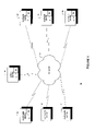
- FIG. 1 is a block diagram of an SOA ES architecture 10 comprising customer devices (CD) 32 , 34 , 36 , agent device (AD) 12 , and supplier devices (SD) 22 , 24 , 26 according to various embodiments.
- Each CD 32 , 34 , 36 may be coupled to the AD 12 via a network 14 where the network may be a local wired or wireless network or a network of networks such as the Internet.
- Each SD 22 , 24 , 26 may also be coupled to the AD 12 via the network 14 where the network may be a local wired or wireless network or a network of networks such as the Internet.
- the AD 12 includes an ES 13 where the ES 13 may be configured to communicate messages between CDs 32 , 34 , 36 and the AD 12 .
- the ES 13 may also be configured to communicate messages between the AD 12 and the SDs 22 , 24 , and 26 .
- Each SD 22 , 24 , 26 may have an ES 23 , 25 , 27 that may be configured to communicate messages between the AD 12 and itself.
- Each ES 13 , 23 , 25 , 27 may represent an organization having processes and document or message protocols.
- a CD 32 may have an ES 33 to process messages from and generate messages for an AD 12 .
- the AD 12 ES 13 may be managed by a first organization
- the CD 32 ES 33 may be managed by a second organization
- one or more of the SD 22 ES 23 , SD 24 , ES 25 , SD 26 ES 27 may be managed by a third organization.
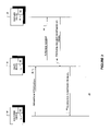
- FIG. 2 is a diagram of document or message communications 40 between an AD 12 , a CD 32 , and a SD 22 according to various embodiments.
- a supplier may provide goods or services and an agent may broker requests for goods or services from a customer to the supplier.
- a customer via a CD 32 may generate a requisition specification message (RSM) or document 42 and forward the RSM to an agent for fulfillment via an AD 12 .
- the agent via an AD 12 may review the RSM 42 and generate a purchase request message (PRM) 44 and forward it to a selected supplier's SD 22 .
- RSM requisition specification message
- PRM purchase request message
- the AD 12 ES 13 may be managed by a first organization
- the CD 32 ES 33 may be managed by a second organization
- the SD 22 ES 23 may be managed by a third organization
- messages 42 , 48 between the CD 32 ES 33 and the AD 12 ES 13 may be cross organizational messages.
- messages 44 , 46 between the SD 22 ES 23 and the AD 12 ES 13 may be cross organizational messages.
- the supplier via the SD 22 may review the PRM 44 and generate a PR acceptance or denial message PRADM 46 accordingly and forward the PRADM 46 to the AD 12 for review.
- the agent via the AD 12 may receive the PRADM 46 and generate a requisition acceptance or denial message RADM 48 .
- the agent via the AD 12 may forward the RADM 48 to the CD 32 .
- the AD 12 may employ an ES 13 to automate the processing of RSMs 42 and PRADMs 46 and generating PRMs 44 and RADMs 48 when appropriate.
- the SD 22 may employ an ES 23 to process PRMs 44 and generate PRADMs 46 when appropriate.
- the CD 32 may employ an ES 33 to generate RSMs 42 and process RADMs 48 .
- the RSM 42 , PRM 44 , PRADM 46 , and RADM 48 may include a predetermined number of fields in a predetermined format and order.
- the ES 13 may be required to have knowledge about the RSM generated by any CD 32 and the PRADM 46 generated by any SD 22 .
- the ES 13 may format the PRM 44 based on the recipient SD 22 .
- the SD 22 ES 23 may also have knowledge about the format of PRM 44 messages received from an AD 12 and may format the PRADM 46 based on the recipient AD 12 .
- Messages 42 , 44 , 46 , 48 betweens ES 33 , 13 , 23 may be configured based on a contextualization standard including a core component technical specification (CCTS), e.g., an automotive order contextualization standard.
- CCTS core component technical specification
- Implementation of the CCTS may require process and document modifications in each ES 13 , 23 , 33 .
- one of the CD 32 , AD 12 , or SD 22 may implement one or more process or document changes that may affect one or more processes or documents in others devices 32 , 12 , 22 .
- the SD 22 may require that all received purchase requests 44 include a customer credit status indication. Accordingly, the SD 22 may configure its ES 23 to expect a credit status indication field in all PRM 44 and include a process or algorithm to evaluate the credit status indication field along with other fields of PRM 44 .
- An AD 12 providing purchase requests 44 to such an SD 22 may be required to configure its purchase request to include a customer credit status indication. Accordingly, the AD 12 ES 13 may need to be configured to determine a customer's credit status (process configuration) and include an indication of the customer's credit status in any purchase requests 44 (document configuration). Further the AD 12 ES 13 may require an RSM 42 from a CD 32 to include one or more fields (document configuration) providing data needed to determine a corresponding customer's credit status. The CD 32 ES 33 may need to be configured to determine, provide, or populate one or more customer identification fields (process configuration) for each requisition specification 42 (document configuration) forwarded to the AD 12 .
- the AD 12 may control one or more aspects of the purchase request 44 record or message configuration including whether the record includes a corresponding customer credit status.
- the AD 12 may configure the purchase request 44 record not to include a customer credit status field (document configuration).
- the AD 12 ES 13 may not evaluate one or more fields of a RSM 42 to determine, provide, or populate a customer credit status field in a PRM 44 (process configuration).
- the CD 32 may or may not be required to include determine, provide, or populate one or more customer identification fields (process configuration) for each RSM 42 (document configuration) forwarded to the AD 12 .
- the customer identification fields may be forwarded in the PRM 44 (document configuration) so a SD 22 ES 23 may determine a customer's credit status (process configuration) based on customer identification fields provided in a purchase request 44 .
- the CD 32 ES 33 may not fill, populate, or include customer identification fields (process configuration) in RSM 42 forwarded to the AD 12 ES 13 .
- the AD 12 ES 13 may not determine customer credit status (process configuration) and may not include or populate customer credit status fields in a PRM 44 forwarded to SD 22 ES 23 (document configuration).
- the AD 12 ES 13 may also not include or populate customer identification fields in a purchase request 44 messages forwarded to SD 22 ES 23 (document configuration).
- the SD 22 ES 23 may not evaluate the customer credit status and may not evaluate the customer identification fields (process configuration) for purchase requests received from the AD 12 ES 13 .
- a process decision of a CD 32 not to include or populate customer identification fields in a RSM 42 may affect document configuration ( 42 , 44 ) and process configuration in the AD 12 ES 13 and SD 22 ES 23 .
- a process decision of one of the AD 12 or SD 22 to determine or to require customer credit status may affect document configuration of the messages 42 , 44 and process configuration of the CD 32 , AD 12 , and SD 22 . Accordingly there may be a correlation between process modifications and document modifications in an ES ( 13 , 23 , 33 ) and across multiple organizations (different ES 13 , 23 , 33 ).
- FIG. 3 is a block diagram of cross organization collaboration 20 , according to an example embodiment.
- An AD 12 ES 13 and a SD 22 ES 23 may be coupled to a collaboration module 16 .
- the AD 12 ES 13 may specify the format of messages it generates for and accepts from the SD 22 ES 23 ;
- the SD 22 ES 23 may specify the format of messages it generates for and accepts from the AD 12 ES 13 ;
- the AD 12 ES 13 may specify the format of messages that it accepts from the SD 22 ES 23 and the SD 22 ES 23 may specify the format of messages that it accepts from the AD 12 ES 13 ;
- a third party may set the format for messages between ADs and SDs, set as a standardization organization (CCTS).
- CCTS standardization organization
- the AD 12 ES 13 and SD 22 ES 23 may each communicate message format requirements to the collaboration module 16 .
- the collaboration module 16 may collect the requirements and provide the requirements to the ES 13 and ES 23 accordingly.
- each SD 22 , SD 24 , SD 26 may have different requirements or expectations for messages it receives or generates.
- the ES 13 may configure its business processes differently as related to each ES 23 . 25 , 27 . These ES 13 business processes may determine message formats for both reception and transmission. Supporting different ESs 23 , 25 , 27 may require numerous business process variations.
- Each configurable model element 80 may have modifiable object attributes such as configuration parameters 82 where an object may be a document or process.
- one or more configuration terms 84 may determine how or when to configure an object parameter 82 .
- a context 86 may define the value of one or more configuration terms 84 .
- the context 86 may relate to a specific enterprise or variations due to collaboration with other ES.
- a context driver 88 may create one or more contexts 86 .
- a related ES may provide configurable element information (CEI).
- the CEI may affect a context driver 88 , a context 86 , or configuration term 84 in an embodiment.
- the context 86 or context driver 88 may be related to contextualization standard such as CCTS or other message, document or process standardization protocol or configuration.
- the method 90 shown in FIG. 5 may be employed to configure an ES model.
- the method 90 may enable a user to select one or more context(s) related to their deployment and retrieve a master ES model related to the selected contexts or contextualization (activity 92 ). The method may then determine whether any configurable elements remain to be configured in the selected model (activity 94 ).
- a configurable element may include one or more attributes to be configured. As noted attributes may relate to one or more processes to be performed by an ES. An attribute configuration may also affect the configuration of one or documents or messages to be generated by or received by an ES. Further each attribute configuration may be related to a configuration parameter 82 or configuration term 84 and may be applied to context 86 or context driver 88 .
- the method 90 may enable a user to configure an attribute (activity 96 ).
- An attribute configuration may be determined as a function of collaboration between the ES and another ES.
- the method 90 may continue configuring attributes until all attributes for the element have been configured (activities 96 , 98 ).
- the method 90 may continue configuring master model elements until all elements have been configured (activity 102 ).
- a AD ES may use a master model related to processing requisition messages and generating purchase requests messages.
- Configurable elements may include whether to determine customer's credit status, type of credit check, and format of the credit status indication.
- the related attributes may include a requisition message format for customer identifiers that may be used to determine the customer's credit status indicator, the process of determining a customer's credit status, and the format of one or more fields providing the customer credit status indicator(s).
- Attribute configuration may affect one or more processes or documents for other ES.
- the method 90 may determine whether a process or document or message for another ES may be affected for each attribute configuration (activity 104 ).
- a customer's credit status indication may be provided by an AD ES.
- the method 90 may determine that any requisition requests from a CD may need to populate or include customer identification fields (process and document configuration for related CD).
- the method 90 may also determine that purchase requests from the AD to a SD may include one or more populated customer credit status indications and inform an SD ES of such a message format, affecting processes and expected document or message format for a related SD ES.
- the method 90 may generate one or more constraint or information messages to related ES (such as to CD or SD) based on updated or configured attributes (activity 98 ) and determine relationship or affect to other ES (activity 104 ).
- any attribute configuration may be prorogated to other ES where the receiving ES may determine whether the attribute configuration affects any processes or document or message formats.
- one or more element configurations may generate configuration parameters for a related ES (subject to collaboration or CBP).
- the method 90 may generate a CEI for each configuration parameter or attribute configuration (activity 98 ) to be forwarded to a related ES and forward or prorogate each CEI to the related ES (activity 106 ).
- the element to be configured may be determined by a CEI received from another ES depending on the relationship between an ES and CEI prorogating ES and the model implemented by the ES.
- the method 150 shown in FIG. 6 may be employed to configure elements of an ES based on received CEI(s).
- the method 150 may determine whether a CEI has been received (activity 152 ).
- the method 150 may evaluate the received CEI to determine whether any local ES elements need to be configured or modified (activity 154 ).
- the CEI message may indicate attribute configuration(s) for one or more elements of the ES that generated the CEI message.
- the CEI message format may be contextualized or adapted to conform to one or more standards.
- the CEI may be rejected or ignored depending on the issuing ES.
- the method may configure the elements and related attributes (activity 156 ).
- the method 150 may determine that the CEI affects a process, document, or message of the ES.
- the method 150 may determine whether one or more configurable model elements are affected by CEI message information.
- the method 150 may then determine the processes, documents, or messages that are related to the affected model elements.
- the method 150 may continue to configure model elements based received CEI(s) (as a function of the relationship with the issuing ES) (activity 158 ).
- the method 150 may forward or generate new CEI for other related ES whose element(s) (processes or communications therebetween) may need to be configured based on the received CEI(s) (activity 162 ).
- element configurations may be prorogated to several CBP ES(s). Accordingly several ES may automatically be configured based on modifications of a master, related ES. Such an embodiment may limit variants between related ES given limited possible variations of a related master ES.
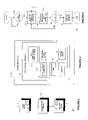
- a device 110 is shown in FIG. 7 that may be used in various embodiments as a CD 32 , 34 , 36 , AD 12 , or SD 22 , 24 , 26 .
- the device 110 may include a central processing unit (CPU) 112 , a random access memory (RAM) 114 , a read only memory (ROM) 116 , a display 118 , a user input device 122 , a transceiver application specific integrated circuit (ASIC) 124 , a microphone 128 , a speaker 132 , and an antenna 134 .
- the CPU 112 may include an ES module 142 and an ES configuration module 144 .
- the RAM 114 may include a CEI queue 138 that may be used to store CEI(s) received from ES(s).
- the ES module 142 and the ES configuration module 144 may be separate elements.
- the ES configuration module 144 may configure elements of the ES module 142 based on user inputs 122 or received CEI messages.
- the ES module 142 may perform business processes, generate messages for related ES, and process messages from related ES according to non-configurable and configurable elements.
- the ROM 116 is coupled to the CPU 112 and may store the program instructions executed by the CPU 112 , the ES configuration module 144 , and the ES module 142 .
- the RAM 114 is coupled to the CPU 112 and may store temporary program data, overhead information, model configuration elements, and CEI queue 138 .
- the user input device 122 may comprise an input device such as a keypad, touch pad screen, track ball, or other similar input device that allows the user to navigate through menus in order to operate the device 110 .
- the display 118 may be an output device such as a CRT, LCD or other similar screen display that enables the user to read, or view ES related information.
- the microphone 128 and the speaker 132 may be incorporated into the device 110 .
- the microphone 128 and the speaker 132 may also be separated from the device 110 .
- Received data may be transmitted to the CPU 112 via a bus 136 where the data may include data received, data to be transmitted, or protocol information.
- the transceiver ASIC 124 may include an instruction set necessary to communicate data signals with the architecture 10 ( FIG. 1 ).
- the ASIC 124 may be coupled to the antenna 134 to communicate signals within the architecture 10 .
- the data may be transferred to the CPU 112 via the bus 136 .
- the data may include overhead information, ES related data or CEI(s) to be processed by the device 110 in accordance with the methods described herein.
- any of the components previously described can be implemented in a number of ways, including embodiments in software.
- the CPU 112 , ES configuration module 144 , ES module 142 , RAM 114 , ROM 116 , CEI queue 138 , transceiver ASIC 124 , antenna 134 , microphone 128 , speaker 132 , user input device 122 , display 118 may all be characterized as “modules” herein.
- the modules may include hardware circuitry, single or multi-processor circuits, memory circuits, software program modules and objects, firmware, and combinations thereof, as desired by the architect of the architecture 10 and as appropriate for particular implementations of various embodiments.
- Applications that may include the novel apparatus and systems of various embodiments include electronic circuitry used in high-speed computers, communication and signal processing circuitry, modems, single or multi-processor modules, single or multiple embedded processors, data switches, and application-specific modules, including multilayer, multi-chip modules.
- Such apparatus and systems may further be included as sub-components within a variety of electronic systems, such as televisions, cellular telephones, personal computers (e.g., laptop computers, desktop computers, handheld computers, tablet computers, etc.), workstations, radios, video players, audio players (e.g., mp3 players), vehicles, medical devices (e.g., heart monitor, blood pressure monitor, etc.) and others.
- Some embodiments may include a number of methods.
- a software program may be launched from a computer-readable medium in a computer-based system to execute functions defined in the software program.
- Various programming languages may be employed to create software programs designed to implement and perform the methods disclosed herein.
- the programs may be structured in an object-orientated format using an object-oriented language such as Java or C++.
- the programs may be structured in a procedure-orientated format using a procedural language, such as assembly or C.
- the software components may communicate using a number of mechanisms well known to those skilled in the art, such as application program interfaces or inter-process communication techniques, including remote procedure calls.
- the teachings of various embodiments are not limited to any particular programming language or environment.
- inventive subject matter may be referred to herein individually or collectively by the term “invention” merely for convenience and without intending to voluntarily limit the scope of this application to any single invention or inventive concept, if more than one is in fact disclosed.
- inventive concept any arrangement calculated to achieve the same purpose may be substituted for the specific embodiments shown.
- This disclosure is intended to cover any and all adaptations or variations of various embodiments. Combinations of the above embodiments, and other embodiments not specifically described herein, will be apparent to those of skill in the art upon reviewing the above description.
Abstract
Description
- The present patent application claims the priority benefit of the filing date of U.S. provisional application No. 60/848,459 filed Sep. 29, 2006, the entire content of which is incorporated herein by reference.
- Various embodiments described herein relate generally to enterprise systems (ES), including apparatus, systems, and methods used in multiple ES.
- A user organization may employ a commercial off-the-shelf (COTS) software package to support operations and management. The software package may be part of an enterprise system (ES) where the ES includes technology and business expertise for a particular enterprise. A service-oriented architecture (SOA) ES may require modeling cross organizational business processes and documents. An ES may provide flexible modeling of numerous process and document variants. In an SOA ES exchanged documents or messages may provide binding agreements between organizations and be closely tied to underlying cross organizational processes. Flexible modeling of SOA ES may produce unmanageable variant combinations.
-
FIG. 1 is a block diagram of SOA ES architecture according to various embodiments. -
FIG. 2 is a diagram of document or message communication between organizations in SOA ES architecture according to various embodiments. -
FIG. 3 is a block diagram of cross organization collaboration according to various embodiments. -
FIG. 4 is a block diagram of an ES according to various embodiments. -
FIG. 5 is a flow diagram illustrating several methods according to various embodiments. -
FIG. 6 is a flow diagram illustrating several methods according to various embodiments. -
FIG. 7 is a block diagram of an article according to various embodiments. -
FIG. 1 is a block diagram of an SOA ESarchitecture 10 comprising customer devices (CD) 32, 34, 36, agent device (AD) 12, and supplier devices (SD) 22, 24, 26 according to various embodiments. EachCD AD 12 via anetwork 14 where the network may be a local wired or wireless network or a network of networks such as the Internet. EachSD AD 12 via thenetwork 14 where the network may be a local wired or wireless network or a network of networks such as the Internet. In an embodiment theAD 12 includes anES 13 where theES 13 may be configured to communicate messages betweenCDs AD 12. The ES 13 may also be configured to communicate messages between theAD 12 and theSDs SD ES AD 12 and itself. Each ES 13, 23, 25, 27 may represent an organization having processes and document or message protocols. In an embodiment, aCD 32 may have anES 33 to process messages from and generate messages for anAD 12. In an embodiment the AD 12 ES 13 may be managed by a first organization, theCD 32 ES 33 may be managed by a second organization, and one or more of the SD 22 ES 23, SD 24, ES 25, SD 26 ES 27 may be managed by a third organization. -
FIG. 2 is a diagram of document ormessage communications 40 between anAD 12, aCD 32, and aSD 22 according to various embodiments. A supplier may provide goods or services and an agent may broker requests for goods or services from a customer to the supplier. In an embodiment, a customer via aCD 32 may generate a requisition specification message (RSM) ordocument 42 and forward the RSM to an agent for fulfillment via anAD 12. The agent via anAD 12 may review theRSM 42 and generate a purchase request message (PRM) 44 and forward it to a selected supplier'sSD 22. In an embodiment the AD 12 ES 13 may be managed by a first organization, theCD 32 ES 33 may be managed by a second organization, and the SD 22 ES 23 may be managed by a third organization Accordinglymessages CD 32 ES 33 and the AD 12 ES 13 may be cross organizational messages. Similarly,messages AD 12ES 13 may be cross organizational messages. - The supplier via the SD 22 may review the
PRM 44 and generate a PR acceptance or denial message PRADM 46 accordingly and forward the PRADM 46 to theAD 12 for review. The agent via theAD 12 may receive the PRADM 46 and generate a requisition acceptance ordenial message RADM 48. The agent via theAD 12 may forward theRADM 48 to theCD 32. TheAD 12 may employ anES 13 to automate the processing ofRSMs 42 andPRADMs 46 and generatingPRMs 44 andRADMs 48 when appropriate. Similarly theSD 22 may employ anES 23 to processPRMs 44 and generatePRADMs 46 when appropriate. TheCD 32 may employ anES 33 to generateRSMs 42 and processRADMs 48. - It is noted that the
RSM 42, PRM 44, PRADM 46, and RADM 48 may include a predetermined number of fields in a predetermined format and order. TheES 13 may be required to have knowledge about the RSM generated by anyCD 32 and the PRADM 46 generated by anySD 22. The ES 13 may format thePRM 44 based on therecipient SD 22. The SD 22 ES 23 may also have knowledge about the format ofPRM 44 messages received from anAD 12 and may format the PRADM 46 based on therecipient AD 12.Messages ES CD 32,AD 12, orSD 22 may implement one or more process or document changes that may affect one or more processes or documents inothers devices - For example, the
SD 22 may require that all receivedpurchase requests 44 include a customer credit status indication. Accordingly, theSD 22 may configure itsES 23 to expect a credit status indication field in allPRM 44 and include a process or algorithm to evaluate the credit status indication field along with other fields ofPRM 44. AnAD 12 providingpurchase requests 44 to such anSD 22 may be required to configure its purchase request to include a customer credit status indication. Accordingly, the AD 12 ES 13 may need to be configured to determine a customer's credit status (process configuration) and include an indication of the customer's credit status in any purchase requests 44 (document configuration). Further theAD 12ES 13 may require anRSM 42 from aCD 32 to include one or more fields (document configuration) providing data needed to determine a corresponding customer's credit status. TheCD 32 ES 33 may need to be configured to determine, provide, or populate one or more customer identification fields (process configuration) for each requisition specification 42 (document configuration) forwarded to theAD 12. - In another embodiment, the
AD 12 may control one or more aspects of thepurchase request 44 record or message configuration including whether the record includes a corresponding customer credit status. TheAD 12 may configure thepurchase request 44 record not to include a customer credit status field (document configuration). Accordingly, theAD 12 ES 13 may not evaluate one or more fields of aRSM 42 to determine, provide, or populate a customer credit status field in a PRM 44 (process configuration). TheCD 32 may or may not be required to include determine, provide, or populate one or more customer identification fields (process configuration) for each RSM 42 (document configuration) forwarded to theAD 12. The customer identification fields may be forwarded in the PRM 44 (document configuration) so aSD 22 ES 23 may determine a customer's credit status (process configuration) based on customer identification fields provided in apurchase request 44. - Further in an embodiment the
CD 32ES 33 may not fill, populate, or include customer identification fields (process configuration) inRSM 42 forwarded to theAD 12ES 13. TheAD 12ES 13 may not determine customer credit status (process configuration) and may not include or populate customer credit status fields in aPRM 44 forwarded to SD 22 ES 23 (document configuration). TheAD 12ES 13 may also not include or populate customer identification fields in apurchase request 44 messages forwarded to SD 22 ES 23 (document configuration). The SD 22 ES 23 may not evaluate the customer credit status and may not evaluate the customer identification fields (process configuration) for purchase requests received from theAD 12ES 13. Accordingly, a process decision of aCD 32 not to include or populate customer identification fields in aRSM 42 may affect document configuration (42, 44) and process configuration in theAD 12ES 13 and SD 22 ES 23. Similarly, a process decision of one of theAD 12 orSD 22 to determine or to require customer credit status may affect document configuration of themessages CD 32,AD 12, andSD 22. Accordingly there may be a correlation between process modifications and document modifications in an ES (13, 23, 33) and across multiple organizations (different ES -
FIG. 3 is a block diagram ofcross organization collaboration 20, according to an example embodiment. AnAD 12ES 13 and aSD 22ES 23 may be coupled to acollaboration module 16. Depending on theES 13 andES 23 and relationship between an agent and supplier: a) theAD 12ES 13 may specify the format of messages it generates for and accepts from theSD 22ES 23; b) theSD 22ES 23 may specify the format of messages it generates for and accepts from theAD 12ES 13; c) theAD 12ES 13 may specify the format of messages that it accepts from theSD 22ES 23 and theSD 22ES 23 may specify the format of messages that it accepts from theAD 12ES 13; and d) a third party may set the format for messages between ADs and SDs, set as a standardization organization (CCTS). - In order to enable communication between an
AD 12ES 13 andSD 22ES 23, a negotiation regarding message format and theunderlying ES 13 andES 23 processes may be performed. TheAD 12ES 13 andSD 22ES 23 may each communicate message format requirements to thecollaboration module 16. Thecollaboration module 16 may collect the requirements and provide the requirements to theES 13 andES 23 accordingly. It is noted that eachSD 22,SD 24,SD 26 may have different requirements or expectations for messages it receives or generates. In order to accommodatevarious ESs ES 13 may configure its business processes differently as related to eachES 23. 25, 27. TheseES 13 business processes may determine message formats for both reception and transmission. Supportingdifferent ESs -
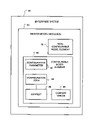
FIG. 4 is a block diagram of anES 50 according to various embodiments. TheES 50 may be employed in a CD, AD, SD, or other processing device. To limit possible variations while permitting model modifications to accommodate collaboration between one or more ES's, theES 50 includes one or more master model module(s). Each module may be related to a specific enterprise. Eachmaster model 60 may includenon-configurable model elements 70 andconfigurable model elements 80. A user may select a specific master model based on its correlation to their enterprise such as a SOA ES or correlation with a specific contextualization standard such as CCTS. - Each
configurable model element 80 may have modifiable object attributes such asconfiguration parameters 82 where an object may be a document or process. In an embodiment one ormore configuration terms 84 may determine how or when to configure anobject parameter 82. Acontext 86 may define the value of one ormore configuration terms 84. Thecontext 86 may relate to a specific enterprise or variations due to collaboration with other ES. Acontext driver 88 may create one ormore contexts 86. A related ES may provide configurable element information (CEI). The CEI may affect acontext driver 88, acontext 86, orconfiguration term 84 in an embodiment. Thecontext 86 orcontext driver 88 may be related to contextualization standard such as CCTS or other message, document or process standardization protocol or configuration. Themethod 90 shown inFIG. 5 may be employed to configure an ES model. - The
method 90 may enable a user to select one or more context(s) related to their deployment and retrieve a master ES model related to the selected contexts or contextualization (activity 92). The method may then determine whether any configurable elements remain to be configured in the selected model (activity 94). In an embodiment a configurable element may include one or more attributes to be configured. As noted attributes may relate to one or more processes to be performed by an ES. An attribute configuration may also affect the configuration of one or documents or messages to be generated by or received by an ES. Further each attribute configuration may be related to aconfiguration parameter 82 orconfiguration term 84 and may be applied tocontext 86 orcontext driver 88. - The
method 90 may enable a user to configure an attribute (activity 96). An attribute configuration may be determined as a function of collaboration between the ES and another ES. Themethod 90 may continue configuring attributes until all attributes for the element have been configured (activities 96, 98). Themethod 90 may continue configuring master model elements until all elements have been configured (activity 102). In the AD, CD, SD architecture a AD ES may use a master model related to processing requisition messages and generating purchase requests messages. Configurable elements may include whether to determine customer's credit status, type of credit check, and format of the credit status indication. The related attributes may include a requisition message format for customer identifiers that may be used to determine the customer's credit status indicator, the process of determining a customer's credit status, and the format of one or more fields providing the customer credit status indicator(s). - Attribute configuration may affect one or more processes or documents for other ES. The
method 90 may determine whether a process or document or message for another ES may be affected for each attribute configuration (activity 104). In the example presented above, a customer's credit status indication may be provided by an AD ES. When the AD ES related process and documents are configured themethod 90 may determine that any requisition requests from a CD may need to populate or include customer identification fields (process and document configuration for related CD). Themethod 90 may also determine that purchase requests from the AD to a SD may include one or more populated customer credit status indications and inform an SD ES of such a message format, affecting processes and expected document or message format for a related SD ES. - The
method 90 may generate one or more constraint or information messages to related ES (such as to CD or SD) based on updated or configured attributes (activity 98) and determine relationship or affect to other ES (activity 104). In an embodiment any attribute configuration may be prorogated to other ES where the receiving ES may determine whether the attribute configuration affects any processes or document or message formats. In an embodiment one or more element configurations may generate configuration parameters for a related ES (subject to collaboration or CBP). Themethod 90 may generate a CEI for each configuration parameter or attribute configuration (activity 98) to be forwarded to a related ES and forward or prorogate each CEI to the related ES (activity 106). - The element to be configured (activity 94) may be determined by a CEI received from another ES depending on the relationship between an ES and CEI prorogating ES and the model implemented by the ES. In an embodiment, the
method 150 shown inFIG. 6 may be employed to configure elements of an ES based on received CEI(s). Themethod 150 may determine whether a CEI has been received (activity 152). Themethod 150 may evaluate the received CEI to determine whether any local ES elements need to be configured or modified (activity 154). In an embodiment the CEI message may indicate attribute configuration(s) for one or more elements of the ES that generated the CEI message. Further the CEI message format may be contextualized or adapted to conform to one or more standards. - The CEI may be rejected or ignored depending on the issuing ES. After determining the element(s) to be configured based on the CEI, the method may configure the elements and related attributes (activity 156). The
method 150 may determine that the CEI affects a process, document, or message of the ES. Themethod 150 may determine whether one or more configurable model elements are affected by CEI message information. Themethod 150 may then determine the processes, documents, or messages that are related to the affected model elements. - The
method 150 may continue to configure model elements based received CEI(s) (as a function of the relationship with the issuing ES) (activity 158). In an embodiment themethod 150 may forward or generate new CEI for other related ES whose element(s) (processes or communications therebetween) may need to be configured based on the received CEI(s) (activity 162). In an embodiment element configurations may be prorogated to several CBP ES(s). Accordingly several ES may automatically be configured based on modifications of a master, related ES. Such an embodiment may limit variants between related ES given limited possible variations of a related master ES. - A
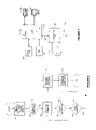
device 110 is shown inFIG. 7 that may be used in various embodiments as aCD AD 12, orSD device 110 may include a central processing unit (CPU) 112, a random access memory (RAM) 114, a read only memory (ROM) 116, adisplay 118, auser input device 122, a transceiver application specific integrated circuit (ASIC) 124, amicrophone 128, aspeaker 132, and anantenna 134. TheCPU 112 may include anES module 142 and anES configuration module 144. TheRAM 114 may include aCEI queue 138 that may be used to store CEI(s) received from ES(s). - In an embodiment, the
ES module 142 and theES configuration module 144 may be separate elements. TheES configuration module 144 may configure elements of theES module 142 based onuser inputs 122 or received CEI messages. TheES module 142 may perform business processes, generate messages for related ES, and process messages from related ES according to non-configurable and configurable elements. - The
ROM 116 is coupled to theCPU 112 and may store the program instructions executed by theCPU 112, theES configuration module 144, and theES module 142. TheRAM 114 is coupled to theCPU 112 and may store temporary program data, overhead information, model configuration elements, andCEI queue 138. Theuser input device 122 may comprise an input device such as a keypad, touch pad screen, track ball, or other similar input device that allows the user to navigate through menus in order to operate thedevice 110. Thedisplay 118 may be an output device such as a CRT, LCD or other similar screen display that enables the user to read, or view ES related information. - The
microphone 128 and thespeaker 132 may be incorporated into thedevice 110. Themicrophone 128 and thespeaker 132 may also be separated from thedevice 110. Received data may be transmitted to theCPU 112 via abus 136 where the data may include data received, data to be transmitted, or protocol information. Thetransceiver ASIC 124 may include an instruction set necessary to communicate data signals with the architecture 10 (FIG. 1 ). TheASIC 124 may be coupled to theantenna 134 to communicate signals within thearchitecture 10. When a data signal is received by thetransceiver ASIC 124, the data may be transferred to theCPU 112 via thebus 136. The data may include overhead information, ES related data or CEI(s) to be processed by thedevice 110 in accordance with the methods described herein. - Any of the components previously described can be implemented in a number of ways, including embodiments in software. Thus, the
CPU 112,ES configuration module 144,ES module 142,RAM 114,ROM 116,CEI queue 138,transceiver ASIC 124,antenna 134,microphone 128,speaker 132,user input device 122,display 118 may all be characterized as “modules” herein. - The modules may include hardware circuitry, single or multi-processor circuits, memory circuits, software program modules and objects, firmware, and combinations thereof, as desired by the architect of the
architecture 10 and as appropriate for particular implementations of various embodiments. - The apparatus and systems of various embodiments may be useful in applications other than ES element configuration. They are not intended to serve as a complete description of all the elements and features of apparatus and systems that might make use of the structures described herein.
- Applications that may include the novel apparatus and systems of various embodiments include electronic circuitry used in high-speed computers, communication and signal processing circuitry, modems, single or multi-processor modules, single or multiple embedded processors, data switches, and application-specific modules, including multilayer, multi-chip modules. Such apparatus and systems may further be included as sub-components within a variety of electronic systems, such as televisions, cellular telephones, personal computers (e.g., laptop computers, desktop computers, handheld computers, tablet computers, etc.), workstations, radios, video players, audio players (e.g., mp3 players), vehicles, medical devices (e.g., heart monitor, blood pressure monitor, etc.) and others. Some embodiments may include a number of methods.
- It may be possible to execute the activities described herein in an order other than the order described. Various activities described with respect to the methods identified herein can be executed in repetitive, serial, or parallel fashion.
- A software program may be launched from a computer-readable medium in a computer-based system to execute functions defined in the software program. Various programming languages may be employed to create software programs designed to implement and perform the methods disclosed herein. The programs may be structured in an object-orientated format using an object-oriented language such as Java or C++. Alternatively, the programs may be structured in a procedure-orientated format using a procedural language, such as assembly or C. The software components may communicate using a number of mechanisms well known to those skilled in the art, such as application program interfaces or inter-process communication techniques, including remote procedure calls. The teachings of various embodiments are not limited to any particular programming language or environment.
- The accompanying drawings that form a part hereof show, by way of illustration and not of limitation, specific embodiments in which the subject matter may be practiced. The embodiments illustrated are described in sufficient detail to enable those skilled in the art to practice the teachings disclosed herein. Other embodiments may be utilized and derived therefrom, such that structural and logical substitutions and changes may be made without departing from the scope of this disclosure. This Detailed Description, therefore, is not to be taken in a limiting sense, and the scope of various embodiments is defined only by the appended claims, along with the full range of equivalents to which such claims are entitled.
- Such embodiments of the inventive subject matter may be referred to herein individually or collectively by the term “invention” merely for convenience and without intending to voluntarily limit the scope of this application to any single invention or inventive concept, if more than one is in fact disclosed. Thus, although specific embodiments have been illustrated and described herein, any arrangement calculated to achieve the same purpose may be substituted for the specific embodiments shown. This disclosure is intended to cover any and all adaptations or variations of various embodiments. Combinations of the above embodiments, and other embodiments not specifically described herein, will be apparent to those of skill in the art upon reviewing the above description.
- The Abstract of the Disclosure is provided to comply with 37 C.F.R. §1.72(b), requiring an abstract that will allow the reader to quickly ascertain the nature of the technical disclosure. It is submitted with the understanding that it will not be used to interpret or limit the scope or meaning of the claims. In the foregoing Detailed Description, various features are grouped together in a single embodiment for the purpose of streamlining the disclosure. This method of disclosure is not to be interpreted to require more features than are expressly recited in each claim. Rather, inventive subject matter may be found in less than all features of a single disclosed embodiment. Thus the following claims are hereby incorporated into the Detailed Description, with each claim standing on its own as a separate embodiment.
Claims (21)
Priority Applications (1)
| Application Number | Priority Date | Filing Date | Title |
|---|---|---|---|
| US11/603,736 US8042090B2 (en) | 2006-09-29 | 2006-11-21 | Integrated configuration of cross organizational business processes |
Applications Claiming Priority (2)
| Application Number | Priority Date | Filing Date | Title |
|---|---|---|---|
| US84845906P | 2006-09-29 | 2006-09-29 | |
| US11/603,736 US8042090B2 (en) | 2006-09-29 | 2006-11-21 | Integrated configuration of cross organizational business processes |
Publications (2)
| Publication Number | Publication Date |
|---|---|
| US20080098355A1 true US20080098355A1 (en) | 2008-04-24 |
| US8042090B2 US8042090B2 (en) | 2011-10-18 |
Family
ID=39319528
Family Applications (1)
| Application Number | Title | Priority Date | Filing Date |
|---|---|---|---|
| US11/603,736 Active 2030-08-18 US8042090B2 (en) | 2006-09-29 | 2006-11-21 | Integrated configuration of cross organizational business processes |
Country Status (1)
| Country | Link |
|---|---|
| US (1) | US8042090B2 (en) |
Cited By (3)
| Publication number | Priority date | Publication date | Assignee | Title |
|---|---|---|---|---|
| US20110296379A1 (en) * | 2010-05-26 | 2011-12-01 | Honeywell International Inc. | Automated method for decoupling avionics application software in an ima system |
| US20130138473A1 (en) * | 2011-11-28 | 2013-05-30 | Sap Ag | Business Process Optimization |
| US20130139164A1 (en) * | 2011-11-28 | 2013-05-30 | Sap Ag | Business Process Optimization |
Families Citing this family (1)
| Publication number | Priority date | Publication date | Assignee | Title |
|---|---|---|---|---|
| US9038037B1 (en) * | 2014-07-22 | 2015-05-19 | Ted J. Biggerstaff | Automatically solving simultaneous type equations for type difference transformations that redesign code |
Citations (31)
| Publication number | Priority date | Publication date | Assignee | Title |
|---|---|---|---|---|
| US5581764A (en) * | 1993-04-30 | 1996-12-03 | Novadigm, Inc. | Distributed computer network including hierarchical resource information structure and related method of distributing resources |
| US6061665A (en) * | 1997-06-06 | 2000-05-09 | Verifone, Inc. | System, method and article of manufacture for dynamic negotiation of a network payment framework |
| US6311226B1 (en) * | 1997-08-29 | 2001-10-30 | Cisco Technology, Inc. | Method and apparatus for dynamic link name negotiation |
| US20020033843A1 (en) * | 2000-05-05 | 2002-03-21 | Loos Michael T. | System and method for mobile software application development and deployment |
| US20020082856A1 (en) * | 2000-08-25 | 2002-06-27 | Thomas Gray | Resource sharing with sliding constraints |
| US20020198727A1 (en) * | 2001-06-22 | 2002-12-26 | International Business Machines Corporation | Method and system using an enterprise framework |
| US6550057B1 (en) * | 1999-08-31 | 2003-04-15 | Accenture Llp | Piecemeal retrieval in an information services patterns environment |
| US20030197733A1 (en) * | 1997-09-30 | 2003-10-23 | Journee Software Corp | Dynamic process-based enterprise computing system and method |
| US6643650B1 (en) * | 2000-05-09 | 2003-11-04 | Sun Microsystems, Inc. | Mechanism and apparatus for using messages to look up documents stored in spaces in a distributed computing environment |
| US6684383B1 (en) * | 1999-09-29 | 2004-01-27 | Kabushiki Kaisha Toshiba | Method for constructing enterprise system |
| US6721776B1 (en) * | 1999-05-12 | 2004-04-13 | Unisys Corporation | Generic DCOM server |
| US6757689B2 (en) * | 2001-02-02 | 2004-06-29 | Hewlett-Packard Development Company, L.P. | Enabling a zero latency enterprise |
| US20040249854A1 (en) * | 2003-03-24 | 2004-12-09 | Barnes-Leon Maria Theresa | Common common object |
| US20050005259A1 (en) * | 2003-03-14 | 2005-01-06 | Infowave Software, Inc. | System and method for communication and mapping of business objects between mobile client devices and a plurality of backend systems |
| US20050027871A1 (en) * | 2003-06-05 | 2005-02-03 | William Bradley | Interoperable systems and methods for peer-to-peer service orchestration |
| US6871346B1 (en) * | 2000-02-11 | 2005-03-22 | Microsoft Corp. | Back-end decoupled management model and management system utilizing same |
| US20050081186A1 (en) * | 2003-10-14 | 2005-04-14 | Microsoft Corporation | System and method for deploying a software build from a plurality of software builds to a target computer |
| US20050144619A1 (en) * | 2002-03-15 | 2005-06-30 | Patrick Newman | System and method for configuring software for distribution |
| US6950862B1 (en) * | 2001-05-07 | 2005-09-27 | 3Com Corporation | System and method for offloading a computational service on a point-to-point communication link |
| US6968535B2 (en) * | 2002-03-21 | 2005-11-22 | Sun Microsystems, Inc. | Service mapping method of enterprise application modeling and development for multi-tier service environments |
| US20060015724A1 (en) * | 2004-07-15 | 2006-01-19 | Amir Naftali | Host credentials authorization protocol |
| US7010573B1 (en) * | 2000-05-09 | 2006-03-07 | Sun Microsystems, Inc. | Message gates using a shared transport in a distributed computing environment |
| US20060114855A1 (en) * | 2004-11-30 | 2006-06-01 | Haihong Zheng | Quality of service (QOS) signaling for a wireless network |
| US20060168070A1 (en) * | 2005-01-06 | 2006-07-27 | Tervela, Inc. | Hardware-based messaging appliance |
| US20070022404A1 (en) * | 2005-07-25 | 2007-01-25 | Liang-Jie Zhang | Method and apparatus for enabling enterprise project management with service oriented resource and using a process profiling framework |
| US20070022383A1 (en) * | 2005-07-22 | 2007-01-25 | International Business Machines Corporation | Mechanism for converting after image data to a delta level change |
| US20070094641A1 (en) * | 2001-12-28 | 2007-04-26 | Darr Timothy P | Product configuration using configuration patterns |
| US20070150387A1 (en) * | 2005-02-25 | 2007-06-28 | Michael Seubert | Consistent set of interfaces derived from a business object model |
| US7526734B2 (en) * | 2004-04-30 | 2009-04-28 | Sap Ag | User interfaces for developing enterprise applications |
| US7721283B2 (en) * | 2004-05-24 | 2010-05-18 | Sap Ag | Deploying a variety of containers in a Java 2 enterprise edition-based architecture |
| US7831693B2 (en) * | 2003-08-18 | 2010-11-09 | Oracle America, Inc. | Structured methodology and design patterns for web services |
-
2006
- 2006-11-21 US US11/603,736 patent/US8042090B2/en active Active
Patent Citations (37)
| Publication number | Priority date | Publication date | Assignee | Title |
|---|---|---|---|---|
| US5581764A (en) * | 1993-04-30 | 1996-12-03 | Novadigm, Inc. | Distributed computer network including hierarchical resource information structure and related method of distributing resources |
| US6061665A (en) * | 1997-06-06 | 2000-05-09 | Verifone, Inc. | System, method and article of manufacture for dynamic negotiation of a network payment framework |
| US6311226B1 (en) * | 1997-08-29 | 2001-10-30 | Cisco Technology, Inc. | Method and apparatus for dynamic link name negotiation |
| US6990636B2 (en) * | 1997-09-30 | 2006-01-24 | Initiate Systems, Inc. | Enterprise workflow screen based navigational process tool system and method |
| US20030197733A1 (en) * | 1997-09-30 | 2003-10-23 | Journee Software Corp | Dynamic process-based enterprise computing system and method |
| US6721776B1 (en) * | 1999-05-12 | 2004-04-13 | Unisys Corporation | Generic DCOM server |
| US6550057B1 (en) * | 1999-08-31 | 2003-04-15 | Accenture Llp | Piecemeal retrieval in an information services patterns environment |
| US6684383B1 (en) * | 1999-09-29 | 2004-01-27 | Kabushiki Kaisha Toshiba | Method for constructing enterprise system |
| US6871346B1 (en) * | 2000-02-11 | 2005-03-22 | Microsoft Corp. | Back-end decoupled management model and management system utilizing same |
| US20020116698A1 (en) * | 2000-05-05 | 2002-08-22 | Marc Lurie | Method for distributing, integrating, and hosting a software platform |
| US20090183138A1 (en) * | 2000-05-05 | 2009-07-16 | @Hand Corporation | System and method for mobile software application development and deployment |
| US7313782B2 (en) * | 2000-05-05 | 2007-12-25 | @Hand Corporation | Method for distributing, integrating, and hosting a software platform |
| US20020033843A1 (en) * | 2000-05-05 | 2002-03-21 | Loos Michael T. | System and method for mobile software application development and deployment |
| US6643650B1 (en) * | 2000-05-09 | 2003-11-04 | Sun Microsystems, Inc. | Mechanism and apparatus for using messages to look up documents stored in spaces in a distributed computing environment |
| US7010573B1 (en) * | 2000-05-09 | 2006-03-07 | Sun Microsystems, Inc. | Message gates using a shared transport in a distributed computing environment |
| US7222345B2 (en) * | 2000-08-25 | 2007-05-22 | Mitel Networks Corporation | Resource sharing with sliding constraints |
| US20020082856A1 (en) * | 2000-08-25 | 2002-06-27 | Thomas Gray | Resource sharing with sliding constraints |
| US6757689B2 (en) * | 2001-02-02 | 2004-06-29 | Hewlett-Packard Development Company, L.P. | Enabling a zero latency enterprise |
| US6950862B1 (en) * | 2001-05-07 | 2005-09-27 | 3Com Corporation | System and method for offloading a computational service on a point-to-point communication link |
| US20020198727A1 (en) * | 2001-06-22 | 2002-12-26 | International Business Machines Corporation | Method and system using an enterprise framework |
| US20070094641A1 (en) * | 2001-12-28 | 2007-04-26 | Darr Timothy P | Product configuration using configuration patterns |
| US20050144619A1 (en) * | 2002-03-15 | 2005-06-30 | Patrick Newman | System and method for configuring software for distribution |
| US6983449B2 (en) * | 2002-03-15 | 2006-01-03 | Electronic Data Systems Corporation | System and method for configuring software for distribution |
| US6968535B2 (en) * | 2002-03-21 | 2005-11-22 | Sun Microsystems, Inc. | Service mapping method of enterprise application modeling and development for multi-tier service environments |
| US20050005259A1 (en) * | 2003-03-14 | 2005-01-06 | Infowave Software, Inc. | System and method for communication and mapping of business objects between mobile client devices and a plurality of backend systems |
| US20040249854A1 (en) * | 2003-03-24 | 2004-12-09 | Barnes-Leon Maria Theresa | Common common object |
| US20050027871A1 (en) * | 2003-06-05 | 2005-02-03 | William Bradley | Interoperable systems and methods for peer-to-peer service orchestration |
| US7831693B2 (en) * | 2003-08-18 | 2010-11-09 | Oracle America, Inc. | Structured methodology and design patterns for web services |
| US20050081186A1 (en) * | 2003-10-14 | 2005-04-14 | Microsoft Corporation | System and method for deploying a software build from a plurality of software builds to a target computer |
| US7526734B2 (en) * | 2004-04-30 | 2009-04-28 | Sap Ag | User interfaces for developing enterprise applications |
| US7721283B2 (en) * | 2004-05-24 | 2010-05-18 | Sap Ag | Deploying a variety of containers in a Java 2 enterprise edition-based architecture |
| US20060015724A1 (en) * | 2004-07-15 | 2006-01-19 | Amir Naftali | Host credentials authorization protocol |
| US20060114855A1 (en) * | 2004-11-30 | 2006-06-01 | Haihong Zheng | Quality of service (QOS) signaling for a wireless network |
| US20060168070A1 (en) * | 2005-01-06 | 2006-07-27 | Tervela, Inc. | Hardware-based messaging appliance |
| US20070150387A1 (en) * | 2005-02-25 | 2007-06-28 | Michael Seubert | Consistent set of interfaces derived from a business object model |
| US20070022383A1 (en) * | 2005-07-22 | 2007-01-25 | International Business Machines Corporation | Mechanism for converting after image data to a delta level change |
| US20070022404A1 (en) * | 2005-07-25 | 2007-01-25 | Liang-Jie Zhang | Method and apparatus for enabling enterprise project management with service oriented resource and using a process profiling framework |
Cited By (4)
| Publication number | Priority date | Publication date | Assignee | Title |
|---|---|---|---|---|
| US20110296379A1 (en) * | 2010-05-26 | 2011-12-01 | Honeywell International Inc. | Automated method for decoupling avionics application software in an ima system |
| US9063800B2 (en) * | 2010-05-26 | 2015-06-23 | Honeywell International Inc. | Automated method for decoupling avionics application software in an IMA system |
| US20130138473A1 (en) * | 2011-11-28 | 2013-05-30 | Sap Ag | Business Process Optimization |
| US20130139164A1 (en) * | 2011-11-28 | 2013-05-30 | Sap Ag | Business Process Optimization |
Also Published As
| Publication number | Publication date |
|---|---|
| US8042090B2 (en) | 2011-10-18 |
Similar Documents
| Publication | Publication Date | Title |
|---|---|---|
| US9304808B2 (en) | Updating a workflow when a user reaches an impasse in the workflow | |
| US8504400B2 (en) | Dynamically optimized distributed cloud computing-based business process management (BPM) system | |
| US8356274B2 (en) | System and methods to create a multi-tenancy software as a service application | |
| US20160335142A1 (en) | Notification Service Processing Method for Business Process Management and Business Process Management Engine | |
| US9524145B2 (en) | Rebuildable service-oriented applications | |
| CN110673964A (en) | Audio playing control method and device of vehicle-mounted system | |
| US8572564B2 (en) | Configuring and constructing applications in a mainframe-based computing environment | |
| US8370281B2 (en) | Self-modification of a mainframe-based business rules engine construction tool | |
| US8539514B2 (en) | Workflow integration and portal systems and methods | |
| US9497096B2 (en) | Dynamic control over tracing of messages received by a message broker | |
| US20140222712A1 (en) | Data acquisition, normalization, and exchange in a retail ecosystem | |
| US8364625B2 (en) | Mainframe-based business rules engine construction tool | |
| US20080109292A1 (en) | Voice-enabled workflow item interface | |
| US9116705B2 (en) | Mainframe-based browser | |
| US20130117055A1 (en) | Techniques to provide enterprise resource planning functions from an e-mail client application | |
| CN111177112A (en) | Database blocking method and device based on operation and maintenance management system and electronic equipment | |
| CN110601880A (en) | Cloud platform, service processing method, command interface and computer equipment | |
| US20180225146A1 (en) | System and methods for transaction-based process management | |
| US8042090B2 (en) | Integrated configuration of cross organizational business processes | |
| CN111258998A (en) | Data verification method, device, medium and electronic equipment | |
| US9934291B2 (en) | Dynamic presentation of a results set by a form-based software application | |
| US9953070B1 (en) | Enterprise resource planning (ERP) system data extraction, loading, and directing | |
| CN109144864B (en) | Method and device for testing window | |
| US20130046840A1 (en) | System and method for dynamically generating an email message | |
| CN114625458A (en) | Page data processing method and device, electronic equipment and storage medium |
Legal Events
| Date | Code | Title | Description |
|---|---|---|---|
| AS | Assignment |
Owner name: SAP AG, GERMANY Free format text: ASSIGNMENT OF ASSIGNORS INTEREST;ASSIGNORS:JANIESCH, CHRISTIAN;DREILING, ALEXANDER;GREINER, ULRIKE B.;AND OTHERS;REEL/FRAME:018637/0157;SIGNING DATES FROM 20061027 TO 20061103 Owner name: SAP AG, GERMANY Free format text: ASSIGNMENT OF ASSIGNORS INTEREST;ASSIGNORS:JANIESCH, CHRISTIAN;DREILING, ALEXANDER;GREINER, ULRIKE B.;AND OTHERS;SIGNING DATES FROM 20061027 TO 20061103;REEL/FRAME:018637/0157 |
|
| FEPP | Fee payment procedure |
Free format text: PAYOR NUMBER ASSIGNED (ORIGINAL EVENT CODE: ASPN); ENTITY STATUS OF PATENT OWNER: LARGE ENTITY |
|
| STCF | Information on status: patent grant |
Free format text: PATENTED CASE |
|
| AS | Assignment |
Owner name: SAP SE, GERMANY Free format text: CHANGE OF NAME;ASSIGNOR:SAP AG;REEL/FRAME:033625/0334 Effective date: 20140707 |
|
| FPAY | Fee payment |
Year of fee payment: 4 |
|
| MAFP | Maintenance fee payment |
Free format text: PAYMENT OF MAINTENANCE FEE, 8TH YEAR, LARGE ENTITY (ORIGINAL EVENT CODE: M1552); ENTITY STATUS OF PATENT OWNER: LARGE ENTITY Year of fee payment: 8 |
|
| MAFP | Maintenance fee payment |
Free format text: PAYMENT OF MAINTENANCE FEE, 12TH YEAR, LARGE ENTITY (ORIGINAL EVENT CODE: M1553); ENTITY STATUS OF PATENT OWNER: LARGE ENTITY Year of fee payment: 12 |