US20080098418A1 - Electronic module for digital television receiver - Google Patents
Electronic module for digital television receiver Download PDFInfo
- Publication number
- US20080098418A1 US20080098418A1 US11/874,912 US87491207A US2008098418A1 US 20080098418 A1 US20080098418 A1 US 20080098418A1 US 87491207 A US87491207 A US 87491207A US 2008098418 A1 US2008098418 A1 US 2008098418A1
- Authority
- US
- United States
- Prior art keywords
- electronic module
- module according
- block
- volatile memory
- memory interface
- Prior art date
- Legal status (The legal status is an assumption and is not a legal conclusion. Google has not performed a legal analysis and makes no representation as to the accuracy of the status listed.)
- Abandoned
Links
Images

Classifications
-
- H—ELECTRICITY
- H04—ELECTRIC COMMUNICATION TECHNIQUE
- H04N—PICTORIAL COMMUNICATION, e.g. TELEVISION
- H04N7/00—Television systems
- H04N7/16—Analogue secrecy systems; Analogue subscription systems
-
- G—PHYSICS
- G06—COMPUTING; CALCULATING OR COUNTING
- G06F—ELECTRIC DIGITAL DATA PROCESSING
- G06F21/00—Security arrangements for protecting computers, components thereof, programs or data against unauthorised activity
- G06F21/70—Protecting specific internal or peripheral components, in which the protection of a component leads to protection of the entire computer
- G06F21/82—Protecting input, output or interconnection devices
- G06F21/85—Protecting input, output or interconnection devices interconnection devices, e.g. bus-connected or in-line devices
-
- H—ELECTRICITY
- H04—ELECTRIC COMMUNICATION TECHNIQUE
- H04N—PICTORIAL COMMUNICATION, e.g. TELEVISION
- H04N21/00—Selective content distribution, e.g. interactive television or video on demand [VOD]
- H04N21/40—Client devices specifically adapted for the reception of or interaction with content, e.g. set-top-box [STB]; Operations thereof
- H04N21/41—Structure of client; Structure of client peripherals
- H04N21/418—External card to be used in combination with the client device, e.g. for conditional access
- H04N21/4181—External card to be used in combination with the client device, e.g. for conditional access for conditional access
-
- H—ELECTRICITY
- H04—ELECTRIC COMMUNICATION TECHNIQUE
- H04N—PICTORIAL COMMUNICATION, e.g. TELEVISION
- H04N21/00—Selective content distribution, e.g. interactive television or video on demand [VOD]
- H04N21/40—Client devices specifically adapted for the reception of or interaction with content, e.g. set-top-box [STB]; Operations thereof
- H04N21/41—Structure of client; Structure of client peripherals
- H04N21/426—Internal components of the client ; Characteristics thereof
- H04N21/42692—Internal components of the client ; Characteristics thereof for reading from or writing on a volatile storage medium, e.g. Random Access Memory [RAM]
-
- H—ELECTRICITY
- H04—ELECTRIC COMMUNICATION TECHNIQUE
- H04N—PICTORIAL COMMUNICATION, e.g. TELEVISION
- H04N21/00—Selective content distribution, e.g. interactive television or video on demand [VOD]
- H04N21/40—Client devices specifically adapted for the reception of or interaction with content, e.g. set-top-box [STB]; Operations thereof
- H04N21/43—Processing of content or additional data, e.g. demultiplexing additional data from a digital video stream; Elementary client operations, e.g. monitoring of home network or synchronising decoder's clock; Client middleware
- H04N21/443—OS processes, e.g. booting an STB, implementing a Java virtual machine in an STB or power management in an STB
- H04N21/4432—Powering on the client, e.g. bootstrap loading using setup parameters being stored locally or received from the server
-
- H—ELECTRICITY
- H04—ELECTRIC COMMUNICATION TECHNIQUE
- H04N—PICTORIAL COMMUNICATION, e.g. TELEVISION
- H04N21/00—Selective content distribution, e.g. interactive television or video on demand [VOD]
- H04N21/80—Generation or processing of content or additional data by content creator independently of the distribution process; Content per se
- H04N21/81—Monomedia components thereof
- H04N21/8166—Monomedia components thereof involving executable data, e.g. software
- H04N21/818—OS software
-
- G—PHYSICS
- G06—COMPUTING; CALCULATING OR COUNTING
- G06F—ELECTRIC DIGITAL DATA PROCESSING
- G06F2221/00—Indexing scheme relating to security arrangements for protecting computers, components thereof, programs or data against unauthorised activity
- G06F2221/21—Indexing scheme relating to G06F21/00 and subgroups addressing additional information or applications relating to security arrangements for protecting computers, components thereof, programs or data against unauthorised activity
- G06F2221/2147—Locking files
Definitions
- the object of the invention is an electronic module for a digital television receiver.
- CA conditional access
- the CA system combines hardware elements (such as descramblers, security chips, Smart Cards) and software elements (CA kernel application, encryption algorithms) to decrypt protected content or to enable specific device functionality.
- the operation of the CA system usually depends on subscription fee payments, and certain users tend to “hack” the system in order to avoid these payments.
- Early CA systems utilized Smart Cards to store user identity and subscription information, but hacking techniques have been developed to produce falsified cards. Later, further hacking techniques have been developed to produce pirated CA software to replace the original software provided by the CA vendor. Therefore, it has become evident that in order to provide a completely safe CA system, all the elements of the system shall be secured to prevent hacking.
- Proprietary software such as an operating system or high-level user applications
- One method to protect such software is to hash or scramble the code with a signature key. The authenticity of software can be checked during start-up of the set-top box by a booter application. Therefore, it is essential to secure the booter application and signature keys against unauthorized access and modifications, as it guarantees the security of the higher-level software.
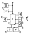
- a conventional set-top box as shown in FIG. 1 , comprises a multimedia CPU 101 which controls the operation of the set-top box and performs stream-processing functions, such as decoding and descrambling.
- the CPU 101 receives data streams through a front-end block 102 , for example a satellite, terrestrial, cable or an IPTV front-end.
- the software executed by the CPU is stored in a non-volatile memory 109 , sharing a memory interface with other peripheral devices via a peripheral interface 106 , such as an Ethernet interface.
- Software is executed in a system RAM 108 , and the received audio/video stream is decoded in a video RAM 107 .
- the CA system elements may cooperate with a smart card placed in a smart card interface 103 .
- a mass storage device 105 e.g. a hard disk, may be used to store additional software or audio/video streams.
- the CPU 101 also communicates with other elements 104 , such as a front panel interface, back end processors, etc.
- the conventional set-top box architecture presented in FIG. 1 has a number of security problems.
- the CPU and individual memory chips, as well as data buses between them are easily accessible.
- Software stored in the memory chips, including CA system components and other proprietary software can be easily read and possibly replaced.
- transmitted data, such as CA keys or descrambled audio/video streams can be easily read as well.
- the memory chips apart from re-programming, can be replaced by other chips with pirated software.
- a conventional method to secure these elements is to cover the elements and data buses with a strong adhesive material, such as an epoxy, to block physical access to these elements.
- a strong adhesive material such as an epoxy
- EP 0961193 A2 entitled “Secure computing device” is known a secure computing system, which is encrypted with a private key.
- a boot ROM of this system on the same integrated circuit as the data processor and inaccessible from outside includes an initialization program and a public key corresponding to the private key. On initialization the boot ROM decrypts at least a verification portion of the program, after which normal operation is enabled.
- US Patent Application Publication No. US 2005/0078936 A1 entitled “Memory card fir digital television decoder and method of processing data using memory card and method of rental memory card” teaches a memory card for a digital television decoder, which has a memory block with a separate data memory area. Moreover, the card also comprises a conditional access circuit for descrambling of data stored in the separate data memory and a controller for controlling the data flow inside the card.
- the present invention solves the aforementioned problems by providing an electronic module comprising a multimedia CPU, a non-volatile memory connected with the CPU via a memory interface, and a buffer or controller configurable to enable or block access to the memory interface for components external to the module.
- the non-volatile memory stores at least a booter application for initializing the start-up of the digital television receiver. It may further store CA system signature keys, high-level software protection keys or a loader application. Such configuration protects integrity of software stored in the non-volatile memory block, especially of the booter, the loader, the CA system kernel, signature keys and serialization data.
- the module provides higher level of security of data and audio/video content by comprising integrated system RAM and video RAM blocks.
- the module may comprise a smart card chip for improved CA system security level.
- the memory interface can be a bus having data, address and control lines whereas the buffer can be configurable to enable or block access to at least one line or to enable or block access to at least 1 ⁇ 3 of the lines.
- the module can be packaged in Chip on Board, Die on Board, Multi Chip Module, Multi Die Module or System in Package technology.
- FIG. 1 shows a conventional set-top box architecture
- FIG. 2 shows a set-top box architecture with an STB module according to the first embodiment of the invention
- FIG. 3 shows a configuration of the buffer of the STB module
- FIG. 4 shows a set-top box architecture with an STB module according to the second embodiment of the invention
- FIG. 5 shows a set-top box architecture with an STB module according to the third embodiment of the invention
- FIG. 6 shows a configuration of internal non-volatile memory of the STB module
- FIG. 7 shows a flow chart of start-up process of the set-top box.
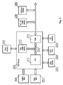
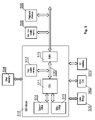
- FIG. 2 presents a set-top box architecture with an electronic module 210 , called an STB module throughout the description, according to the first embodiment of the invention.
- the STB module 210 is provided in a package, which contents are inaccessible in a direct way from the outside.
- the STB module can be made in a technology such as Chip on Board (COB), Die on Board (DOB), Multi Chip Module (MCM), Multi Die Module (MDM) or System in Package (SiP).
- COB Chip on Board
- DOB Die on Board
- MCM Multi Chip Module
- MDM Multi Die Module
- SiP System in Package
- the STB module 210 comprises a multimedia CPU 211 , an internal non-volatile memory 212 communicating with the CPU 211 via a memory interface 220 and a buffer or controller 213 .
- the buffer 213 is configurable to enable or block access to the memory interface 220 for components 206 , 209 external to the module. Therefore, the buffer enables the CPU to exchange data with components external to the STB module and blocks access to the contents of the non-volatile memory 212 block and data transmitted between the multimedia CPU 211 and the non-volatile memory block 212 .
- a more detailed configuration of the buffer 213 is shown in FIG. 3 .
- the internal non-volatile memory 212 e.g.
- NOR Flash memory die stores at least a booter application for secure start-up of the system, and preferably other elements, as shown in details in FIG. 6 .
- booter application By securing the booter application, all other system elements whose authenticity is checked by the booter are protected as well.
- the CA system elements placed in the internal non-volatile memory 212 are also secure.
- the set-top box may be equipped with another non-volatile memory block 209 , for example a Flash NAND memory chip, external to the module 210 .
- the size of that memory block may be substantially greater than the size of the internal non-volatile memory block, to store high-level operating system and applications.
- the external non-volatile memory block 209 and the peripheral interface 206 communicate with the CPU in the STB module via the memory interface 220 .
- the access to the internal non-volatile memory block 212 via this interface 220 is controlled by means of the buffer 213 .
- Such configuration i.e. use of the same memory interface for both the internal 212 and external 209 non-volatile memory blocks allows use of a standard processor, designed for a conventional application as shown in FIG. 1 . This allows for using standard components inside the STB module 210 , which considerably reduces the costs and allows for an easy design of the module.
- the other elements of the set-top box architecture such as a front-end block 202 , an SC interface 203 , others elements 204 , a mass storage 205 , a video RAM 207 and a system RAM 208 communicate with the STB module 210 in a conventional way, as described in conjunction with FIG. 1 .
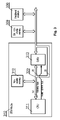
- FIG. 3 presents a configuration of the buffer or controller 313 of the STB module 310 .
- the CPU 311 has a memory interface 320 via which both the internal non-volatile memory and external modules, such as external non-volatile memory 309 or peripheral interfaces 306 , may communicate. It is essential to block access to the contents of the non-volatile memory block 312 and data transmitted between the CPU 311 and the non-volatile memory block 312 for the external modules. This is made possible by the buffer 313 , which is configurable to enable or block access to the memory interface 320 for the external components.
- the memory interface 320 is a bus having 50 lines, being data, address and control lines.
- the buffer 313 may control access to all the bus lines, or, as presented in the example, only to a number of lines, for example 20 lines. Securing only a part of lines does not limit safety, as information on only part of address or only part of data word is useless for a potential hacker. Limiting the number of protected lines simplifies the design of the module, as a relatively small buffer 313 (or a small number of buffers) can be used. A secure protection can be obtained by protecting a reasonable number of lines, for example at least 1 ⁇ 3 of the memory bus lines. A 74LVC245 chip can be used as a buffer.
- the buffer 313 operation is controlled by the CPU 311 via a buffer control bus. In case the CPU 311 accesses the internal memory 312 of the module, it sets the buffer 313 to a state in which access to the memory interface from the outside is blocked. The buffer 313 is unlocked only in situation where communication with external modules is necessary.
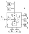
- FIG. 4 presents a set-top box architecture with an STB module 410 according to the second embodiment of the invention.
- the STB module 410 besides a non-volatile memory 412 and a buffer or controller 413 , comprises an internal smart card chip 414 used by the CA system.
- Such configuration provides complete security of data transmitted between the CPU 411 and the smart card chip 414 , such as descrambling keys for received video and audio content.
- the set-top box may be equipped with a peripheral interface 406 and another non-volatile memory block 409 .
- an external smart card interface 403 can be provided for additional applications or for additional CA system having lower security requirements.
- the other elements of the set-top box architecture such as a front-end block 402 , others elements 404 , a mass storage 405 , a video RAM 407 and a system RAM 408 , communicate with the STB module 410 in a conventional way, as described in conjunction with FIG. 1 .
- FIG. 5 presents a set-top box architecture with an STB module 510 according to the third embodiment of the invention.
- the STB module 510 besides a non-volatile memory 512 and a buffer or controller 513 , comprises integrated Video RAM 515 and System RAM 514 chips. Integration of the Video RAM 515 enables greater level of content protection, as the descrambled content is no longer accessible outside the STB module 510 . Moreover, integration of the System RAM 514 enables greater level of CA system protection, by blocking access to CA keys and fragments of CA system software executed in the system RAM 514 .
- the other elements of the set-top box architecture such as a front-end block 502 , an SC interface 503 , others elements 504 , a mass storage 505 , a peripheral interface 506 and another non-volatile memory block 509 , communicate with the STB module 510 in a conventional way, as described in conjunction with FIG. 1 .
- FIG. 4 and 5 can be combined, to provide an STB module with integrated CPU, non-volatile memory, buffers, System RAM, Video RAM and smart card chip, thereby providing the greatest level of security.
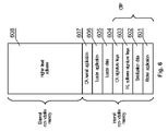
- FIG. 6 presents a configuration of the non-volatile memory of the set-top box.
- the internal non-volatile memory comprises a booter application 601 for initializing the start-up process of the set-top box according to the procedure of FIG. 7 . It may also comprise additional data, such as serialization data 602 , high level software signature keys 603 , CA signature keys 604 or loader data 605 .
- the internal memory or its fragment can be configured as an OTP (one-time-programming) block, which guarantees that its contents will not be changed.
- OTP one-time-programming
- loader application 606 used to update higher-level software 607
- the internal memory if its size permits, may store CA kernel application 607 for improved CA system security.
- Data in the external memory such as high-level software 608
- high level software signature keys 603 such that it is accessible only to STB modules having specific serialization data 602 .
- the encryption may be performed according to the X.509 standard. This enables traceability of many production parameters, such as the quantity of modules produced, their configuration, the client and software versions. It also prevents the software from unauthorized modifications, monitoring or replacement
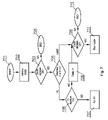
- FIG. 7 presents a flow chart of start-up process of the set-top box.
- the procedure is initiated in step 701 at a power-up or after a hard reset of the set-top box.
- the booter application is initialized in step 702 and the booter signature is checked in step 703 to ascertain that the booter application has not been changed by unauthorized persons. If the booter signature is not correct, the procedure stops in step 704 . If the booter signature is correct, it is determined in step 705 which application should be executed next—a loader or a high level application.
- the loader can be executed at the first power-up of the set-top box at customer premises or if a flag has been set by the high level software.
- the high level application is executed if no need for software update has been signaled.
- the signature of the high level application is checked in step 706 and if it is correct, the high level application is executed in step 707 . If the signature is not correct, the high level code can be deleted in step 708 and the procedure continues to initiate the loader.
- the loader signature is checked in step 709 and if it is not correct, then the procedure stops in step 710 . If the loader signature is correct, the loader application is executed in step 711 for updating the software.
Abstract
An electronic module for a digital television receiver comprises a multimedia CPU (211), a non-volatile memory block (212) connected with the multimedia CPU (211) via a memory interface (220) and storing a booter application for initializing the start-up of the digital television receiver, and a buffer (213) connected to the memory interface (220), configurable to enable or block access to the memory interface (220) for components (206, 209) external to the module. The invention provides a solution for securing the set-top box elements, including CA system elements and proprietary set-top box software, to prevent unauthorized access to them, their monitoring or replacement.
Description
- This application claims priority to the European Patent Application No. EP06465015.3, filed Oct. 19, 2006, the contents of which are incorporated herein by reference.
- 1. Field of the Invention
- The object of the invention is an electronic module for a digital television receiver.
- 2. Brief Description of the Background of the Invention Including Prior Art
- In a design of a digital television receiver, also called a set-top box (STB), a lot of attention must be paid to security issues. The elements often subject to security risks are the conditional access (CA) system and proprietary low- and high-level software modules.
- The CA system combines hardware elements (such as descramblers, security chips, Smart Cards) and software elements (CA kernel application, encryption algorithms) to decrypt protected content or to enable specific device functionality. The operation of the CA system usually depends on subscription fee payments, and certain users tend to “hack” the system in order to avoid these payments. Early CA systems utilized Smart Cards to store user identity and subscription information, but hacking techniques have been developed to produce falsified cards. Later, further hacking techniques have been developed to produce pirated CA software to replace the original software provided by the CA vendor. Therefore, it has become evident that in order to provide a completely safe CA system, all the elements of the system shall be secured to prevent hacking.
- Proprietary software, such as an operating system or high-level user applications, can be also subject to pirate attacks, e.g. for the purpose of unlocking specific functionality or cloning the software at unauthorized devices. One method to protect such software is to hash or scramble the code with a signature key. The authenticity of software can be checked during start-up of the set-top box by a booter application. Therefore, it is essential to secure the booter application and signature keys against unauthorized access and modifications, as it guarantees the security of the higher-level software.
- A conventional set-top box, as shown in
FIG. 1 , comprises amultimedia CPU 101 which controls the operation of the set-top box and performs stream-processing functions, such as decoding and descrambling. TheCPU 101 receives data streams through a front-end block 102, for example a satellite, terrestrial, cable or an IPTV front-end. The software executed by the CPU is stored in anon-volatile memory 109, sharing a memory interface with other peripheral devices via aperipheral interface 106, such as an Ethernet interface. Software is executed in asystem RAM 108, and the received audio/video stream is decoded in avideo RAM 107. The CA system elements may cooperate with a smart card placed in asmart card interface 103. Amass storage device 105, e.g. a hard disk, may be used to store additional software or audio/video streams. TheCPU 101 also communicates withother elements 104, such as a front panel interface, back end processors, etc. - The conventional set-top box architecture presented in
FIG. 1 has a number of security problems. For example, the CPU and individual memory chips, as well as data buses between them are easily accessible. Software stored in the memory chips, including CA system components and other proprietary software can be easily read and possibly replaced. Furthermore, transmitted data, such as CA keys or descrambled audio/video streams, can be easily read as well. Moreover, apart from re-programming, the memory chips can be replaced by other chips with pirated software. A conventional method to secure these elements is to cover the elements and data buses with a strong adhesive material, such as an epoxy, to block physical access to these elements. However, such solution introduces a substantial cost at the production stage. Further, it does not guarantee traceability of proprietary software, which can be copied and duplicated in unauthorized devices produced by unauthorized parties. Moreover, elements covered by the epoxy cannot be replaced and in order to service the set-top box, the whole printed circuit board must be changed. - From the European Patent Application Publication No. EP 0961193 A2 entitled “Secure computing device” is known a secure computing system, which is encrypted with a private key. A boot ROM of this system on the same integrated circuit as the data processor and inaccessible from outside includes an initialization program and a public key corresponding to the private key. On initialization the boot ROM decrypts at least a verification portion of the program, after which normal operation is enabled.
- In turn the US Patent Application Publication No. US 2005/0078936 A1 entitled “Memory card fir digital television decoder and method of processing data using memory card and method of rental memory card” teaches a memory card for a digital television decoder, which has a memory block with a separate data memory area. Moreover, the card also comprises a conditional access circuit for descrambling of data stored in the separate data memory and a controller for controlling the data flow inside the card.
- It is an object of the present invention to provide a better solution for securing the set-top box elements, including CA system elements and proprietary set-top box software, to prevent unauthorized access to them, their monitoring or replacement.
- It is a further object of the present invention to provide a solution for secure traceability of proprietary software.
- These and other objects and advantages of the present invention will become apparent from the detailed description, which follows.
- The present invention solves the aforementioned problems by providing an electronic module comprising a multimedia CPU, a non-volatile memory connected with the CPU via a memory interface, and a buffer or controller configurable to enable or block access to the memory interface for components external to the module. The non-volatile memory stores at least a booter application for initializing the start-up of the digital television receiver. It may further store CA system signature keys, high-level software protection keys or a loader application. Such configuration protects integrity of software stored in the non-volatile memory block, especially of the booter, the loader, the CA system kernel, signature keys and serialization data. In addition, the module provides higher level of security of data and audio/video content by comprising integrated system RAM and video RAM blocks. Further, the module may comprise a smart card chip for improved CA system security level. Moreover, the memory interface can be a bus having data, address and control lines whereas the buffer can be configurable to enable or block access to at least one line or to enable or block access to at least ⅓ of the lines. The module can be packaged in Chip on Board, Die on Board, Multi Chip Module, Multi Die Module or System in Package technology.
- The invention will now be described by way of example and with reference to the accompanying drawings in which:
-
FIG. 1 shows a conventional set-top box architecture; -
FIG. 2 shows a set-top box architecture with an STB module according to the first embodiment of the invention; -
FIG. 3 shows a configuration of the buffer of the STB module; -
FIG. 4 shows a set-top box architecture with an STB module according to the second embodiment of the invention; -
FIG. 5 shows a set-top box architecture with an STB module according to the third embodiment of the invention; -
FIG. 6 shows a configuration of internal non-volatile memory of the STB module; and -
FIG. 7 shows a flow chart of start-up process of the set-top box. -
FIG. 2 presents a set-top box architecture with anelectronic module 210, called an STB module throughout the description, according to the first embodiment of the invention. - The
STB module 210 is provided in a package, which contents are inaccessible in a direct way from the outside. For example, the STB module can be made in a technology such as Chip on Board (COB), Die on Board (DOB), Multi Chip Module (MCM), Multi Die Module (MDM) or System in Package (SiP). Such solution guarantees physical security of data stored and transmitted within the module, including essential CA system data and proprietary low- and high-level software. - In the first embodiment, the
STB module 210 comprises amultimedia CPU 211, an internalnon-volatile memory 212 communicating with theCPU 211 via amemory interface 220 and a buffer orcontroller 213. Thebuffer 213 is configurable to enable or block access to thememory interface 220 forcomponents non-volatile memory 212 block and data transmitted between themultimedia CPU 211 and thenon-volatile memory block 212. A more detailed configuration of thebuffer 213 is shown inFIG. 3 . The internalnon-volatile memory 212, e.g. a NOR Flash memory die, stores at least a booter application for secure start-up of the system, and preferably other elements, as shown in details inFIG. 6 . By securing the booter application, all other system elements whose authenticity is checked by the booter are protected as well. The CA system elements placed in the internalnon-volatile memory 212 are also secure. - The set-top box may be equipped with another
non-volatile memory block 209, for example a Flash NAND memory chip, external to themodule 210. The size of that memory block may be substantially greater than the size of the internal non-volatile memory block, to store high-level operating system and applications. The externalnon-volatile memory block 209 and theperipheral interface 206 communicate with the CPU in the STB module via thememory interface 220. The access to the internalnon-volatile memory block 212 via thisinterface 220 is controlled by means of thebuffer 213. Such configuration, i.e. use of the same memory interface for both the internal 212 and external 209 non-volatile memory blocks allows use of a standard processor, designed for a conventional application as shown inFIG. 1 . This allows for using standard components inside theSTB module 210, which considerably reduces the costs and allows for an easy design of the module. - The other elements of the set-top box architecture, such as a front-
end block 202, anSC interface 203,others elements 204, amass storage 205, avideo RAM 207 and asystem RAM 208 communicate with theSTB module 210 in a conventional way, as described in conjunction withFIG. 1 . -
FIG. 3 presents a configuration of the buffer orcontroller 313 of theSTB module 310. TheCPU 311 has amemory interface 320 via which both the internal non-volatile memory and external modules, such as externalnon-volatile memory 309 orperipheral interfaces 306, may communicate. It is essential to block access to the contents of thenon-volatile memory block 312 and data transmitted between theCPU 311 and thenon-volatile memory block 312 for the external modules. This is made possible by thebuffer 313, which is configurable to enable or block access to thememory interface 320 for the external components. In the presented example, thememory interface 320 is a bus having 50 lines, being data, address and control lines. Thebuffer 313 may control access to all the bus lines, or, as presented in the example, only to a number of lines, for example 20 lines. Securing only a part of lines does not limit safety, as information on only part of address or only part of data word is useless for a potential hacker. Limiting the number of protected lines simplifies the design of the module, as a relatively small buffer 313 (or a small number of buffers) can be used. A secure protection can be obtained by protecting a reasonable number of lines, for example at least ⅓ of the memory bus lines. A 74LVC245 chip can be used as a buffer. Thebuffer 313 operation is controlled by theCPU 311 via a buffer control bus. In case theCPU 311 accesses theinternal memory 312 of the module, it sets thebuffer 313 to a state in which access to the memory interface from the outside is blocked. Thebuffer 313 is unlocked only in situation where communication with external modules is necessary. -
FIG. 4 presents a set-top box architecture with anSTB module 410 according to the second embodiment of the invention. - In comparison to the embodiment shown in
FIG. 2 , theSTB module 410, besides anon-volatile memory 412 and a buffer orcontroller 413, comprises an internalsmart card chip 414 used by the CA system. Such configuration provides complete security of data transmitted between theCPU 411 and thesmart card chip 414, such as descrambling keys for received video and audio content. The set-top box may be equipped with aperipheral interface 406 and anothernon-volatile memory block 409. - In addition, an external
smart card interface 403 can be provided for additional applications or for additional CA system having lower security requirements. - The other elements of the set-top box architecture, such as a front-
end block 402,others elements 404, amass storage 405, avideo RAM 407 and asystem RAM 408, communicate with theSTB module 410 in a conventional way, as described in conjunction withFIG. 1 . -
FIG. 5 presents a set-top box architecture with anSTB module 510 according to the third embodiment of the invention. - In comparison to the embodiment shown in
FIG. 2 , theSTB module 510, besides anon-volatile memory 512 and a buffer orcontroller 513, comprisesintegrated Video RAM 515 andSystem RAM 514 chips. Integration of theVideo RAM 515 enables greater level of content protection, as the descrambled content is no longer accessible outside theSTB module 510. Moreover, integration of theSystem RAM 514 enables greater level of CA system protection, by blocking access to CA keys and fragments of CA system software executed in thesystem RAM 514. - The other elements of the set-top box architecture, such as a front-
end block 502, anSC interface 503,others elements 504, amass storage 505, aperipheral interface 506 and anothernon-volatile memory block 509, communicate with theSTB module 510 in a conventional way, as described in conjunction withFIG. 1 . - Further embodiments are possible, such as integrating only Video RAM or System RAM inside the STB module. Moreover, embodiments of
FIG. 4 and 5 can be combined, to provide an STB module with integrated CPU, non-volatile memory, buffers, System RAM, Video RAM and smart card chip, thereby providing the greatest level of security. -
FIG. 6 presents a configuration of the non-volatile memory of the set-top box. The internal non-volatile memory comprises abooter application 601 for initializing the start-up process of the set-top box according to the procedure ofFIG. 7 . It may also comprise additional data, such asserialization data 602, high levelsoftware signature keys 603,CA signature keys 604 orloader data 605. As an option, the internal memory or its fragment can be configured as an OTP (one-time-programming) block, which guarantees that its contents will not be changed. - Other applications can be stored in the internal or in the external non-volatile memory, depending on the system design. For example, the
loader application 606, used to update higher-level software 607, can be stored in the internal memory together with loader data. The internal memory, if its size permits, may storeCA kernel application 607 for improved CA system security. - Data in the external memory, such as high-
level software 608, is encrypted using high levelsoftware signature keys 603 such that it is accessible only to STB modules havingspecific serialization data 602. For example, the encryption may be performed according to the X.509 standard. This enables traceability of many production parameters, such as the quantity of modules produced, their configuration, the client and software versions. It also prevents the software from unauthorized modifications, monitoring or replacement -
FIG. 7 presents a flow chart of start-up process of the set-top box. The procedure is initiated instep 701 at a power-up or after a hard reset of the set-top box. First, the booter application is initialized instep 702 and the booter signature is checked instep 703 to ascertain that the booter application has not been changed by unauthorized persons. If the booter signature is not correct, the procedure stops instep 704. If the booter signature is correct, it is determined instep 705 which application should be executed next—a loader or a high level application. The loader can be executed at the first power-up of the set-top box at customer premises or if a flag has been set by the high level software. The high level application is executed if no need for software update has been signaled. The signature of the high level application is checked instep 706 and if it is correct, the high level application is executed instep 707. If the signature is not correct, the high level code can be deleted instep 708 and the procedure continues to initiate the loader. The loader signature is checked instep 709 and if it is not correct, then the procedure stops instep 710. If the loader signature is correct, the loader application is executed instep 711 for updating the software. - The preferred embodiment having been thus described, it will now be evident to those skilled in the art that further variation thereto may be contemplated. Such variations are not regarded as a departure from the invention, the true scope of the invention being set forth in the claims appended hereto.
Claims (14)
1. An electronic module for a digital television receiver, comprising:
a multimedia CPU (210);
a non-volatile memory block (211) connected with the multimedia CPU (210) via a memory interface (220, 320) and storing a booter application (601) for initializing the start-up of the digital television receiver; and
a buffer (213, 313) connected to the memory interface (220, 320), configurable to enable or block access to the memory interface (220, 320) for components (206, 209) external to the module.
2. The electronic module according to claim 1 , wherein the non-volatile memory block (211) has a one-time-programming block and the booter application (601) is stored in the one-time-programming block.
3. The electronic module according to claim 1 , wherein the non-volatile memory block (211) further stores a CA kernel application (607).
4. The electronic module according to claim 1 , wherein the non-volatile memory (211) block further stores signature keys.
5. The electronic module according to claim 4 , wherein the signature keys are CA system signature keys (604).
6. The electronic module according to claim 4 , wherein the signature keys are high level software protection keys (603).
7. The electronic module according to claim 1 , wherein the non-volatile memory block (211) further stores a loader application (606) for updating the higher-level software.
8. The electronic module according to claim 1 , wherein the non-volatile memory block (211) further stores serialization data (602), unique for the module.
9. The electronic module according to claim 1 , wherein the electronic module further comprises a smart card chip (414) connected to the multimedia CPU (410).
10. The electronic module according to claim 1 , wherein the electronic module further comprises a system RAM (514) connected to the multimedia CPU (511) for executing applications operated by the multimedia CPU (511).
11. The electronic module according to claim 1 , wherein the electronic module further comprises a video RAM (515) connected to the multimedia CPU (511) for storing video data decoded by the multimedia CPU (511).
12. The electronic module according to claim 1 , wherein the memory interface (320) is a bus having data, address and control lines and the buffer (313) is configurable to enable or block access to at least one line.
13. The electronic module according to claim 1 , wherein the memory interface (320) is a bus having data, address and control lines and the buffer (313) is configurable to enable or block access to at least ⅓ of the lines.
14. The electronic module according to claim 1 , wherein the electronic module is packaged in Chip on Board (COB), Die on Board (DOB), Multi Chip Module (MCM), Multi Die Module (MDM) or System in Package (SiP) technology.
Applications Claiming Priority (2)
| Application Number | Priority Date | Filing Date | Title |
|---|---|---|---|
| EP06465015.3 | 2006-10-19 | ||
| EP06465015A EP1914990A1 (en) | 2006-10-19 | 2006-10-19 | Electronic module for digital television receiver |
Publications (1)
| Publication Number | Publication Date |
|---|---|
| US20080098418A1 true US20080098418A1 (en) | 2008-04-24 |
Family
ID=37814644
Family Applications (1)
| Application Number | Title | Priority Date | Filing Date |
|---|---|---|---|
| US11/874,912 Abandoned US20080098418A1 (en) | 2006-10-19 | 2007-10-19 | Electronic module for digital television receiver |
Country Status (2)
| Country | Link |
|---|---|
| US (1) | US20080098418A1 (en) |
| EP (1) | EP1914990A1 (en) |
Cited By (6)
| Publication number | Priority date | Publication date | Assignee | Title |
|---|---|---|---|---|
| US20110093904A1 (en) * | 2009-10-15 | 2011-04-21 | Sony Corporation | Motion picture providing apparatus, motion picture providing method, and program |
| US20110133826A1 (en) * | 2009-12-07 | 2011-06-09 | Stmicroelectronics (R&D) Ltd | Integrated circuit package with multiple dies and queue allocation |
| US20110138164A1 (en) * | 2009-12-04 | 2011-06-09 | Lg Electronics Inc. | Digital broadcast receiver and booting method of digital broadcast receiver |
| US20120033139A1 (en) * | 2010-08-09 | 2012-02-09 | Shaori Guo | Fast-booting broadcast television receiver |
| US20120226915A1 (en) * | 2011-03-04 | 2012-09-06 | James Mitch Zollinger | Content Playback APIS Using Encrypted Streams |
| US9105316B2 (en) | 2009-12-07 | 2015-08-11 | Stmicroelectronics (Research & Development) Limited | Integrated circuit package with multiple dies and a multiplexed communications interface |
Families Citing this family (7)
| Publication number | Priority date | Publication date | Assignee | Title |
|---|---|---|---|---|
| EP1968316A1 (en) | 2007-03-06 | 2008-09-10 | Nagravision S.A. | Method to control the access to conditional access audio/video content |
| ATE484148T1 (en) * | 2008-02-11 | 2010-10-15 | Nagravision Sa | METHOD FOR UPDATING AND MANAGING AN APPLICATION FOR PROCESSING AUDIOVISUAL DATA IN A MULTIMEDIA DEVICE THROUGH A CONDITIONAL ACCESS MODULE |
| EP2727329B1 (en) | 2011-07-01 | 2017-08-23 | Nagravision S.A. | A method for playing repeatable events on a media player |
| CN102520999A (en) * | 2011-12-14 | 2012-06-27 | 康佳集团股份有限公司 | Method for omitting external chip FLASH |
| KR101927435B1 (en) * | 2011-12-22 | 2018-12-11 | 삼성전자주식회사 | Electronic apparatus and control method thereof |
| CN103365655A (en) * | 2013-06-20 | 2013-10-23 | 广州赛姆科技资讯有限公司 | Method for recording operation track of safe monitoring system |
| FR3085814A1 (en) * | 2018-09-11 | 2020-03-13 | Neotion | COMMUNICATION SYSTEM BETWEEN A CAM MODULE AND A MOBILE TERMINAL WITH A CONNECTION TO THE INTERNET NETWORK. |
Citations (8)
| Publication number | Priority date | Publication date | Assignee | Title |
|---|---|---|---|---|
| US20020116706A1 (en) * | 1999-12-14 | 2002-08-22 | Ardavan Bahraini | Selection between an in-band and an out-of-band channel for downloading code to a set top box |
| US20050078936A1 (en) * | 2003-10-10 | 2005-04-14 | Advanced Digital Broadcast Polska Sp. Z O.O. | Memory card for digital television decoder and method of processing data using memory card and method of rental of memory cards |
| US20060112266A1 (en) * | 2004-11-22 | 2006-05-25 | Research In Motion Limited | Method and device for authenticating software |
| US20070186237A1 (en) * | 2004-01-27 | 2007-08-09 | Masahiro Takatori | Television receiver and digital broadcast system |
| US7284268B2 (en) * | 2002-05-16 | 2007-10-16 | Meshnetworks, Inc. | System and method for a routing device to securely share network data with a host utilizing a hardware firewall |
| US7404054B2 (en) * | 2003-05-06 | 2008-07-22 | Renesas Technology Corp. | Information processing device and processor |
| US7526785B1 (en) * | 1999-09-25 | 2009-04-28 | Hewlett-Packard Development Company, L.P. | Trusted computing platform for restricting use of data |
| US7636838B2 (en) * | 2006-01-05 | 2009-12-22 | Broadcom Corporation | Method and system for handling operation of multiple devices within a single system-on-chip (SoC) integrated circuit (IC) |
Family Cites Families (5)
| Publication number | Priority date | Publication date | Assignee | Title |
|---|---|---|---|---|
| US5666516A (en) * | 1993-12-16 | 1997-09-09 | International Business Machines Corporation | Protected programmable memory cartridge having selective access circuitry |
| US6026016A (en) * | 1998-05-11 | 2000-02-15 | Intel Corporation | Methods and apparatus for hardware block locking in a nonvolatile memory |
| DE69942712D1 (en) * | 1998-05-29 | 2010-10-14 | Texas Instruments Inc | Secure computing device |
| US20030084440A1 (en) * | 2001-10-26 | 2003-05-01 | George Lownes | Method of providing a code upgrade to a host device having a smart card interface |
| US20040243783A1 (en) * | 2003-05-30 | 2004-12-02 | Zhimin Ding | Method and apparatus for multi-mode operation in a semiconductor circuit |
-
2006
- 2006-10-19 EP EP06465015A patent/EP1914990A1/en not_active Withdrawn
-
2007
- 2007-10-19 US US11/874,912 patent/US20080098418A1/en not_active Abandoned
Patent Citations (8)
| Publication number | Priority date | Publication date | Assignee | Title |
|---|---|---|---|---|
| US7526785B1 (en) * | 1999-09-25 | 2009-04-28 | Hewlett-Packard Development Company, L.P. | Trusted computing platform for restricting use of data |
| US20020116706A1 (en) * | 1999-12-14 | 2002-08-22 | Ardavan Bahraini | Selection between an in-band and an out-of-band channel for downloading code to a set top box |
| US7284268B2 (en) * | 2002-05-16 | 2007-10-16 | Meshnetworks, Inc. | System and method for a routing device to securely share network data with a host utilizing a hardware firewall |
| US7404054B2 (en) * | 2003-05-06 | 2008-07-22 | Renesas Technology Corp. | Information processing device and processor |
| US20050078936A1 (en) * | 2003-10-10 | 2005-04-14 | Advanced Digital Broadcast Polska Sp. Z O.O. | Memory card for digital television decoder and method of processing data using memory card and method of rental of memory cards |
| US20070186237A1 (en) * | 2004-01-27 | 2007-08-09 | Masahiro Takatori | Television receiver and digital broadcast system |
| US20060112266A1 (en) * | 2004-11-22 | 2006-05-25 | Research In Motion Limited | Method and device for authenticating software |
| US7636838B2 (en) * | 2006-01-05 | 2009-12-22 | Broadcom Corporation | Method and system for handling operation of multiple devices within a single system-on-chip (SoC) integrated circuit (IC) |
Cited By (11)
| Publication number | Priority date | Publication date | Assignee | Title |
|---|---|---|---|---|
| US20110093904A1 (en) * | 2009-10-15 | 2011-04-21 | Sony Corporation | Motion picture providing apparatus, motion picture providing method, and program |
| US20110138164A1 (en) * | 2009-12-04 | 2011-06-09 | Lg Electronics Inc. | Digital broadcast receiver and booting method of digital broadcast receiver |
| WO2011068392A3 (en) * | 2009-12-04 | 2011-11-10 | Lg Electronics Inc. | Digital broadcast receiver and booting method of digital broadcast receiver |
| US8583909B2 (en) | 2009-12-04 | 2013-11-12 | Lg Electronics Inc. | Digital broadcast receiver and booting method of digital broadcast receiver |
| US20110133826A1 (en) * | 2009-12-07 | 2011-06-09 | Stmicroelectronics (R&D) Ltd | Integrated circuit package with multiple dies and queue allocation |
| US9105316B2 (en) | 2009-12-07 | 2015-08-11 | Stmicroelectronics (Research & Development) Limited | Integrated circuit package with multiple dies and a multiplexed communications interface |
| US9367517B2 (en) * | 2009-12-07 | 2016-06-14 | Stmicroelectronics (Research & Development) Limited | Integrated circuit package with multiple dies and queue allocation |
| US20120033139A1 (en) * | 2010-08-09 | 2012-02-09 | Shaori Guo | Fast-booting broadcast television receiver |
| US8891022B2 (en) * | 2010-08-09 | 2014-11-18 | Telegent Systems, Inc. | Fast-booting broadcast television receiver |
| US20120226915A1 (en) * | 2011-03-04 | 2012-09-06 | James Mitch Zollinger | Content Playback APIS Using Encrypted Streams |
| US8532290B2 (en) * | 2011-03-04 | 2013-09-10 | Netflix, Inc. | Content playback APIS using encrypted streams |
Also Published As
| Publication number | Publication date |
|---|---|
| EP1914990A1 (en) | 2008-04-23 |
Similar Documents
| Publication | Publication Date | Title |
|---|---|---|
| US20080098418A1 (en) | Electronic module for digital television receiver | |
| US8060732B2 (en) | Multiple purpose integrated circuit | |
| US8042157B2 (en) | System for restricting data access | |
| US6711683B1 (en) | Compresses video decompression system with encryption of compressed data stored in video buffer | |
| EP1826694B1 (en) | Method and system for secure system-on-a-chip architecture for multimedia data processing | |
| US6775778B1 (en) | Secure computing device having boot read only memory verification of program code | |
| US6266754B1 (en) | Secure computing device including operating system stored in non-relocatable page of memory | |
| EP2847703B1 (en) | Hardware enforced output security settings | |
| EP2436184B1 (en) | Method for providing access control to media services | |
| US20120079287A1 (en) | Firmware Authentication and Deciphering for Secure TV Receiver | |
| US20070186117A1 (en) | Secure processor-based system and method | |
| US20120060039A1 (en) | Code Download and Firewall for Embedded Secure Application | |
| US8738930B2 (en) | Chip integrated protection means | |
| US20120042157A1 (en) | RAM Based Security Element for Embedded Applications | |
| MXPA06014008A (en) | Security module component. | |
| US20140082658A1 (en) | Terminal based on conditional access technology | |
| EP1855224B1 (en) | Method and system for command authentication to achieve a secure interface | |
| JP2003529963A (en) | Method and apparatus for preventing piracy of digital content | |
| TWI490724B (en) | Method for loading a code of at least one software module | |
| US20080189539A1 (en) | Computer system for authenticating requested software application through operating system and method thereof | |
| KR101266251B1 (en) | Method and apparatus for securing digital content | |
| EP1978467A1 (en) | Integrated circuit and method for secure execution of software | |
| US10503663B2 (en) | Method and device for secure processing of encrypted data |
Legal Events
| Date | Code | Title | Description |
|---|---|---|---|
| AS | Assignment |
Owner name: ADVANCED DIGITAL BROADCAST S.A., SWITZERLAND Free format text: ASSIGNMENT OF ASSIGNORS INTEREST;ASSIGNORS:DABROWA, ANDRZEJ;SZCZESNY, KONRAD;SERGIEL, PRZEMYSLAW;REEL/FRAME:019985/0094 Effective date: 20071004 |
|
| STCB | Information on status: application discontinuation |
Free format text: ABANDONED -- FAILURE TO RESPOND TO AN OFFICE ACTION |