US20090099434A1 - Oxygen-effect free analyte sensor - Google Patents
Oxygen-effect free analyte sensor Download PDFInfo
- Publication number
- US20090099434A1 US20090099434A1 US12/172,589 US17258908A US2009099434A1 US 20090099434 A1 US20090099434 A1 US 20090099434A1 US 17258908 A US17258908 A US 17258908A US 2009099434 A1 US2009099434 A1 US 2009099434A1
- Authority
- US
- United States
- Prior art keywords
- sensor
- analyte
- dehydrogenase
- alkyl
- glucose
- Prior art date
- Legal status (The legal status is an assumption and is not a legal conclusion. Google has not performed a legal analysis and makes no representation as to the accuracy of the status listed.)
- Granted
Links
- 239000012491 analyte Substances 0.000 title claims abstract description 154
- 238000000034 method Methods 0.000 claims abstract description 28
- -1 —OH Chemical group 0.000 claims description 111
- WQZGKKKJIJFFOK-GASJEMHNSA-N Glucose Natural products OC[C@H]1OC(O)[C@H](O)[C@@H](O)[C@@H]1O WQZGKKKJIJFFOK-GASJEMHNSA-N 0.000 claims description 73
- 239000008103 glucose Substances 0.000 claims description 73
- 229910052723 transition metal Inorganic materials 0.000 claims description 73
- 239000003446 ligand Substances 0.000 claims description 65
- 150000003624 transition metals Chemical class 0.000 claims description 62
- 125000003118 aryl group Chemical group 0.000 claims description 56
- 238000012545 processing Methods 0.000 claims description 56
- 125000000217 alkyl group Chemical group 0.000 claims description 45
- 125000003545 alkoxy group Chemical group 0.000 claims description 33
- 238000012544 monitoring process Methods 0.000 claims description 33
- 239000000758 substrate Substances 0.000 claims description 30
- 229910052762 osmium Inorganic materials 0.000 claims description 26
- 108010050375 Glucose 1-Dehydrogenase Proteins 0.000 claims description 25
- 101710088194 Dehydrogenase Proteins 0.000 claims description 24
- 125000004414 alkyl thio group Chemical group 0.000 claims description 24
- 125000003282 alkyl amino group Chemical group 0.000 claims description 23
- 125000004663 dialkyl amino group Chemical group 0.000 claims description 23
- JUJWROOIHBZHMG-UHFFFAOYSA-N Pyridine Chemical class C1=CC=NC=C1 JUJWROOIHBZHMG-UHFFFAOYSA-N 0.000 claims description 22
- SYQBFIAQOQZEGI-UHFFFAOYSA-N osmium atom Chemical group [Os] SYQBFIAQOQZEGI-UHFFFAOYSA-N 0.000 claims description 21
- 125000003342 alkenyl group Chemical group 0.000 claims description 19
- 150000001412 amines Chemical class 0.000 claims description 19
- VWWQXMAJTJZDQX-UYBVJOGSSA-N flavin adenine dinucleotide Chemical group C1=NC2=C(N)N=CN=C2N1[C@@H]([C@H](O)[C@@H]1O)O[C@@H]1CO[P@](O)(=O)O[P@@](O)(=O)OC[C@@H](O)[C@@H](O)[C@@H](O)CN1C2=NC(=O)NC(=O)C2=NC2=C1C=C(C)C(C)=C2 VWWQXMAJTJZDQX-UYBVJOGSSA-N 0.000 claims description 18
- 229920001577 copolymer Polymers 0.000 claims description 17
- RAXXELZNTBOGNW-UHFFFAOYSA-N imidazole Chemical class C1=CNC=N1 RAXXELZNTBOGNW-UHFFFAOYSA-N 0.000 claims description 17
- 235000019162 flavin adenine dinucleotide Nutrition 0.000 claims description 16
- 239000011714 flavin adenine dinucleotide Substances 0.000 claims description 16
- 229940093632 flavin-adenine dinucleotide Drugs 0.000 claims description 16
- NOESYZHRGYRDHS-UHFFFAOYSA-N insulin Chemical compound N1C(=O)C(NC(=O)C(CCC(N)=O)NC(=O)C(CCC(O)=O)NC(=O)C(C(C)C)NC(=O)C(NC(=O)CN)C(C)CC)CSSCC(C(NC(CO)C(=O)NC(CC(C)C)C(=O)NC(CC=2C=CC(O)=CC=2)C(=O)NC(CCC(N)=O)C(=O)NC(CC(C)C)C(=O)NC(CCC(O)=O)C(=O)NC(CC(N)=O)C(=O)NC(CC=2C=CC(O)=CC=2)C(=O)NC(CSSCC(NC(=O)C(C(C)C)NC(=O)C(CC(C)C)NC(=O)C(CC=2C=CC(O)=CC=2)NC(=O)C(CC(C)C)NC(=O)C(C)NC(=O)C(CCC(O)=O)NC(=O)C(C(C)C)NC(=O)C(CC(C)C)NC(=O)C(CC=2NC=NC=2)NC(=O)C(CO)NC(=O)CNC2=O)C(=O)NCC(=O)NC(CCC(O)=O)C(=O)NC(CCCNC(N)=N)C(=O)NCC(=O)NC(CC=3C=CC=CC=3)C(=O)NC(CC=3C=CC=CC=3)C(=O)NC(CC=3C=CC(O)=CC=3)C(=O)NC(C(C)O)C(=O)N3C(CCC3)C(=O)NC(CCCCN)C(=O)NC(C)C(O)=O)C(=O)NC(CC(N)=O)C(O)=O)=O)NC(=O)C(C(C)CC)NC(=O)C(CO)NC(=O)C(C(C)O)NC(=O)C1CSSCC2NC(=O)C(CC(C)C)NC(=O)C(NC(=O)C(CCC(N)=O)NC(=O)C(CC(N)=O)NC(=O)C(NC(=O)C(N)CC=1C=CC=CC=1)C(C)C)CC1=CN=CN1 NOESYZHRGYRDHS-UHFFFAOYSA-N 0.000 claims description 16
- 239000004971 Cross linker Substances 0.000 claims description 15
- 239000012528 membrane Substances 0.000 claims description 15
- 150000002500 ions Chemical class 0.000 claims description 13
- 230000004044 response Effects 0.000 claims description 13
- 125000003178 carboxy group Chemical group [H]OC(*)=O 0.000 claims description 12
- UMJSCPRVCHMLSP-UHFFFAOYSA-N pyridine Chemical class COC1=CC=CN=C1 UMJSCPRVCHMLSP-UHFFFAOYSA-N 0.000 claims description 11
- 150000002148 esters Chemical class 0.000 claims description 10
- 125000000717 hydrazino group Chemical group [H]N([*])N([H])[H] 0.000 claims description 10
- 125000000449 nitro group Chemical group [O-][N+](*)=O 0.000 claims description 10
- 238000012546 transfer Methods 0.000 claims description 10
- 125000005236 alkanoylamino group Chemical group 0.000 claims description 9
- 125000004453 alkoxycarbonyl group Chemical group 0.000 claims description 9
- 125000004457 alkyl amino carbonyl group Chemical group 0.000 claims description 9
- 150000001350 alkyl halides Chemical class 0.000 claims description 9
- 125000005533 aryl carboxamido group Chemical group 0.000 claims description 9
- 125000004473 dialkylaminocarbonyl group Chemical group 0.000 claims description 9
- 229940079593 drug Drugs 0.000 claims description 9
- 239000003814 drug Substances 0.000 claims description 9
- OAKJQQAXSVQMHS-UHFFFAOYSA-N Hydrazine Chemical class NN OAKJQQAXSVQMHS-UHFFFAOYSA-N 0.000 claims description 8
- 102000004877 Insulin Human genes 0.000 claims description 8
- 108090001061 Insulin Proteins 0.000 claims description 8
- ISWSIDIOOBJBQZ-UHFFFAOYSA-N Phenol Chemical class OC1=CC=CC=C1 ISWSIDIOOBJBQZ-UHFFFAOYSA-N 0.000 claims description 8
- 125000005276 alkyl hydrazino group Chemical group 0.000 claims description 8
- 229940125396 insulin Drugs 0.000 claims description 8
- 125000006539 C12 alkyl group Chemical group [H]C([H])([H])C([H])([H])C([H])([H])C([H])([H])C([H])([H])C([H])([H])C([H])([H])C([H])([H])C([H])([H])C([H])([H])C([H])([H])C([H])([H])* 0.000 claims description 7
- BAWFJGJZGIEFAR-NNYOXOHSSA-N NAD zwitterion Chemical compound NC(=O)C1=CC=C[N+]([C@H]2[C@@H]([C@H](O)[C@@H](COP([O-])(=O)OP(O)(=O)OC[C@@H]3[C@H]([C@@H](O)[C@@H](O3)N3C4=NC=NC(N)=C4N=C3)O)O2)O)=C1 BAWFJGJZGIEFAR-NNYOXOHSSA-N 0.000 claims description 7
- KJTLSVCANCCWHF-UHFFFAOYSA-N Ruthenium Chemical group [Ru] KJTLSVCANCCWHF-UHFFFAOYSA-N 0.000 claims description 7
- 229910006069 SO3H Inorganic materials 0.000 claims description 7
- 150000008052 alkyl sulfonates Chemical class 0.000 claims description 7
- 150000004820 halides Chemical class 0.000 claims description 7
- MMXZSJMASHPLLR-UHFFFAOYSA-N pyrroloquinoline quinone Chemical compound C12=C(C(O)=O)C=C(C(O)=O)N=C2C(=O)C(=O)C2=C1NC(C(=O)O)=C2 MMXZSJMASHPLLR-UHFFFAOYSA-N 0.000 claims description 7
- 229910052707 ruthenium Inorganic materials 0.000 claims description 7
- 239000003574 free electron Substances 0.000 claims description 6
- 150000002576 ketones Chemical class 0.000 claims description 6
- HRPVXLWXLXDGHG-UHFFFAOYSA-N Acrylamide Chemical class NC(=O)C=C HRPVXLWXLXDGHG-UHFFFAOYSA-N 0.000 claims description 5
- NOWKCMXCCJGMRR-UHFFFAOYSA-N Aziridine Chemical class C1CN1 NOWKCMXCCJGMRR-UHFFFAOYSA-N 0.000 claims description 5
- 150000001299 aldehydes Chemical class 0.000 claims description 5
- 125000000033 alkoxyamino group Chemical group 0.000 claims description 5
- 229940101270 nicotinamide adenine dinucleotide (nad) Drugs 0.000 claims description 5
- 125000004400 (C1-C12) alkyl group Chemical group 0.000 claims description 4
- AVXURJPOCDRRFD-UHFFFAOYSA-N Hydroxylamine Chemical class ON AVXURJPOCDRRFD-UHFFFAOYSA-N 0.000 claims description 4
- 150000001266 acyl halides Chemical class 0.000 claims description 4
- 150000002391 heterocyclic compounds Chemical class 0.000 claims description 4
- 125000002887 hydroxy group Chemical group [H]O* 0.000 claims description 4
- 150000002463 imidates Chemical class 0.000 claims description 4
- 239000012948 isocyanate Chemical class 0.000 claims description 4
- 150000002513 isocyanates Chemical class 0.000 claims description 4
- 229920001223 polyethylene glycol Polymers 0.000 claims description 4
- 150000003461 sulfonyl halides Chemical class 0.000 claims description 4
- 229910052720 vanadium Chemical group 0.000 claims description 4
- AOBIOSPNXBMOAT-UHFFFAOYSA-N 2-[2-(oxiran-2-ylmethoxy)ethoxymethyl]oxirane Chemical compound C1OC1COCCOCC1CO1 AOBIOSPNXBMOAT-UHFFFAOYSA-N 0.000 claims description 3
- PEEHTFAAVSWFBL-UHFFFAOYSA-N Maleimide Chemical class O=C1NC(=O)C=C1 PEEHTFAAVSWFBL-UHFFFAOYSA-N 0.000 claims description 3
- 239000002202 Polyethylene glycol Substances 0.000 claims description 3
- 125000000852 azido group Chemical group *N=[N+]=[N-] 0.000 claims description 3
- 125000002791 glucosyl group Chemical group C1([C@H](O)[C@@H](O)[C@H](O)[C@H](O1)CO)* 0.000 claims description 3
- 150000002540 isothiocyanates Chemical class 0.000 claims description 3
- 125000004642 (C1-C12) alkoxy group Chemical group 0.000 claims 2
- SYEWHONLFGZGLK-UHFFFAOYSA-N 2-[1,3-bis(oxiran-2-ylmethoxy)propan-2-yloxymethyl]oxirane Chemical group C1OC1COCC(OCC1OC1)COCC1CO1 SYEWHONLFGZGLK-UHFFFAOYSA-N 0.000 claims 2
- IAYPIBMASNFSPL-UHFFFAOYSA-N Ethylene oxide Chemical group C1CO1 IAYPIBMASNFSPL-UHFFFAOYSA-N 0.000 claims 2
- 229920003171 Poly (ethylene oxide) Chemical group 0.000 claims 2
- 150000002924 oxiranes Chemical class 0.000 claims 2
- KCXFHTAICRTXLI-UHFFFAOYSA-N propane-1-sulfonic acid Chemical group CCCS(O)(=O)=O KCXFHTAICRTXLI-UHFFFAOYSA-N 0.000 claims 2
- 150000003573 thiols Chemical class 0.000 claims 2
- LEONUFNNVUYDNQ-UHFFFAOYSA-N vanadium atom Chemical group [V] LEONUFNNVUYDNQ-UHFFFAOYSA-N 0.000 claims 2
- 230000003213 activating effect Effects 0.000 claims 1
- 230000008878 coupling Effects 0.000 claims 1
- 238000010168 coupling process Methods 0.000 claims 1
- 238000005859 coupling reaction Methods 0.000 claims 1
- 229910052760 oxygen Inorganic materials 0.000 abstract description 34
- 239000001301 oxygen Substances 0.000 abstract description 34
- 230000000694 effects Effects 0.000 abstract description 9
- MYMOFIZGZYHOMD-UHFFFAOYSA-N Dioxygen Chemical compound O=O MYMOFIZGZYHOMD-UHFFFAOYSA-N 0.000 abstract description 4
- 230000000712 assembly Effects 0.000 abstract description 2
- 238000000429 assembly Methods 0.000 abstract description 2
- 239000012472 biological sample Substances 0.000 abstract description 2
- 239000010410 layer Substances 0.000 description 84
- WQZGKKKJIJFFOK-VFUOTHLCSA-N beta-D-glucose Chemical compound OC[C@H]1O[C@@H](O)[C@H](O)[C@@H](O)[C@@H]1O WQZGKKKJIJFFOK-VFUOTHLCSA-N 0.000 description 72
- 229920000642 polymer Polymers 0.000 description 72
- 150000001875 compounds Chemical class 0.000 description 36
- 239000000243 solution Substances 0.000 description 34
- QVGXLLKOCUKJST-UHFFFAOYSA-N atomic oxygen Chemical compound [O] QVGXLLKOCUKJST-UHFFFAOYSA-N 0.000 description 32
- XLYOFNOQVPJJNP-UHFFFAOYSA-N water Chemical compound O XLYOFNOQVPJJNP-UHFFFAOYSA-N 0.000 description 32
- 229940088598 enzyme Drugs 0.000 description 28
- 102000004190 Enzymes Human genes 0.000 description 27
- 108090000790 Enzymes Proteins 0.000 description 27
- 230000015572 biosynthetic process Effects 0.000 description 27
- 238000003786 synthesis reaction Methods 0.000 description 27
- 239000012992 electron transfer agent Substances 0.000 description 24
- 238000012360 testing method Methods 0.000 description 23
- 239000003054 catalyst Substances 0.000 description 22
- 230000006854 communication Effects 0.000 description 19
- 238000004891 communication Methods 0.000 description 19
- 239000000523 sample Substances 0.000 description 19
- 125000001424 substituent group Chemical group 0.000 description 18
- 238000006243 chemical reaction Methods 0.000 description 17
- 238000004132 cross linking Methods 0.000 description 16
- 239000000463 material Substances 0.000 description 16
- 125000002496 methyl group Chemical group [H]C([H])([H])* 0.000 description 16
- 241000894007 species Species 0.000 description 16
- 210000004369 blood Anatomy 0.000 description 14
- 239000008280 blood Substances 0.000 description 14
- 238000003780 insertion Methods 0.000 description 14
- 230000037431 insertion Effects 0.000 description 14
- 235000019420 glucose oxidase Nutrition 0.000 description 13
- 125000005208 trialkylammonium group Chemical group 0.000 description 13
- 0 [1*]N1C(C2=NC([6*])=C([5*])N2[2*])=NC([3*])=C1[4*] Chemical compound [1*]N1C(C2=NC([6*])=C([5*])N2[2*])=NC([3*])=C1[4*] 0.000 description 12
- 230000008859 change Effects 0.000 description 12
- 230000006870 function Effects 0.000 description 12
- 239000000047 product Substances 0.000 description 12
- ROFVEXUMMXZLPA-UHFFFAOYSA-N Bipyridyl Chemical class N1=CC=CC=C1C1=CC=CC=N1 ROFVEXUMMXZLPA-UHFFFAOYSA-N 0.000 description 11
- 239000000203 mixture Substances 0.000 description 11
- 238000006722 reduction reaction Methods 0.000 description 11
- HVEHTNLSYGZELD-UHFFFAOYSA-N 2,2'-biimidazole Chemical compound N1=CC=NC1=C1N=CC=N1 HVEHTNLSYGZELD-UHFFFAOYSA-N 0.000 description 10
- HEDRZPFGACZZDS-UHFFFAOYSA-N Chloroform Chemical compound ClC(Cl)Cl HEDRZPFGACZZDS-UHFFFAOYSA-N 0.000 description 10
- MHAJPDPJQMAIIY-UHFFFAOYSA-N Hydrogen peroxide Chemical compound OO MHAJPDPJQMAIIY-UHFFFAOYSA-N 0.000 description 10
- 238000006056 electrooxidation reaction Methods 0.000 description 10
- 229920002006 poly(N-vinylimidazole) polymer Polymers 0.000 description 10
- LFQSCWFLJHTTHZ-UHFFFAOYSA-N Ethanol Chemical compound CCO LFQSCWFLJHTTHZ-UHFFFAOYSA-N 0.000 description 9
- LYCAIKOWRPUZTN-UHFFFAOYSA-N Ethylene glycol Chemical compound OCCO LYCAIKOWRPUZTN-UHFFFAOYSA-N 0.000 description 9
- 108010015776 Glucose oxidase Proteins 0.000 description 9
- 239000004366 Glucose oxidase Substances 0.000 description 9
- JVTAAEKCZFNVCJ-UHFFFAOYSA-M Lactate Chemical compound CC(O)C([O-])=O JVTAAEKCZFNVCJ-UHFFFAOYSA-M 0.000 description 9
- OKKJLVBELUTLKV-UHFFFAOYSA-N Methanol Chemical compound OC OKKJLVBELUTLKV-UHFFFAOYSA-N 0.000 description 9
- 229940127090 anticoagulant agent Drugs 0.000 description 9
- 239000003146 anticoagulant agent Substances 0.000 description 9
- 125000004093 cyano group Chemical group *C#N 0.000 description 9
- 238000001514 detection method Methods 0.000 description 9
- 229940116332 glucose oxidase Drugs 0.000 description 9
- 230000000670 limiting effect Effects 0.000 description 9
- 230000009467 reduction Effects 0.000 description 9
- XEEYBQQBJWHFJM-UHFFFAOYSA-N Iron Chemical compound [Fe] XEEYBQQBJWHFJM-UHFFFAOYSA-N 0.000 description 8
- 150000001450 anions Chemical class 0.000 description 8
- 210000001124 body fluid Anatomy 0.000 description 8
- 239000010839 body fluid Substances 0.000 description 8
- 239000000872 buffer Substances 0.000 description 8
- 230000007423 decrease Effects 0.000 description 8
- 238000005259 measurement Methods 0.000 description 8
- SZXUTTGMFUSMCE-UHFFFAOYSA-N 2-(1h-imidazol-2-yl)pyridine Chemical compound C1=CNC(C=2N=CC=CC=2)=N1 SZXUTTGMFUSMCE-UHFFFAOYSA-N 0.000 description 7
- VYPSYNLAJGMNEJ-UHFFFAOYSA-N Silicium dioxide Chemical compound O=[Si]=O VYPSYNLAJGMNEJ-UHFFFAOYSA-N 0.000 description 7
- 229910021607 Silver chloride Inorganic materials 0.000 description 7
- 230000001419 dependent effect Effects 0.000 description 7
- 238000001727 in vivo Methods 0.000 description 7
- 229910052751 metal Inorganic materials 0.000 description 7
- 230000003647 oxidation Effects 0.000 description 7
- 238000007254 oxidation reaction Methods 0.000 description 7
- 229920000075 poly(4-vinylpyridine) Polymers 0.000 description 7
- 229920006395 saturated elastomer Polymers 0.000 description 7
- HKZLPVFGJNLROG-UHFFFAOYSA-M silver monochloride Chemical compound [Cl-].[Ag+] HKZLPVFGJNLROG-UHFFFAOYSA-M 0.000 description 7
- 125000003396 thiol group Chemical class [H]S* 0.000 description 7
- VEXZGXHMUGYJMC-UHFFFAOYSA-M Chloride anion Chemical compound [Cl-] VEXZGXHMUGYJMC-UHFFFAOYSA-M 0.000 description 6
- 238000010586 diagram Methods 0.000 description 6
- 125000002883 imidazolyl group Chemical group 0.000 description 6
- 238000002513 implantation Methods 0.000 description 6
- 238000001802 infusion Methods 0.000 description 6
- 238000009413 insulation Methods 0.000 description 6
- 239000002184 metal Substances 0.000 description 6
- 229920003023 plastic Polymers 0.000 description 6
- 239000004033 plastic Substances 0.000 description 6
- 239000002243 precursor Substances 0.000 description 6
- 230000002829 reductive effect Effects 0.000 description 6
- 238000000967 suction filtration Methods 0.000 description 6
- 150000003568 thioethers Chemical class 0.000 description 6
- OKTJSMMVPCPJKN-UHFFFAOYSA-N Carbon Chemical compound [C] OKTJSMMVPCPJKN-UHFFFAOYSA-N 0.000 description 5
- 230000008901 benefit Effects 0.000 description 5
- 150000003857 carboxamides Chemical class 0.000 description 5
- 230000000875 corresponding effect Effects 0.000 description 5
- 238000012377 drug delivery Methods 0.000 description 5
- 210000003722 extracellular fluid Anatomy 0.000 description 5
- 239000012530 fluid Substances 0.000 description 5
- 125000000623 heterocyclic group Chemical group 0.000 description 5
- 238000007726 management method Methods 0.000 description 5
- 238000012806 monitoring device Methods 0.000 description 5
- 229920006254 polymer film Polymers 0.000 description 5
- 239000002244 precipitate Substances 0.000 description 5
- 239000000741 silica gel Substances 0.000 description 5
- 229910002027 silica gel Inorganic materials 0.000 description 5
- 239000002904 solvent Substances 0.000 description 5
- 238000003756 stirring Methods 0.000 description 5
- 239000000725 suspension Substances 0.000 description 5
- 229910001428 transition metal ion Inorganic materials 0.000 description 5
- 238000005292 vacuum distillation Methods 0.000 description 5
- BPYKTIZUTYGOLE-IFADSCNNSA-N Bilirubin Chemical compound N1C(=O)C(C)=C(C=C)\C1=C\C1=C(C)C(CCC(O)=O)=C(CC2=C(C(C)=C(\C=C/3C(=C(C=C)C(=O)N\3)C)N2)CCC(O)=O)N1 BPYKTIZUTYGOLE-IFADSCNNSA-N 0.000 description 4
- RTZKZFJDLAIYFH-UHFFFAOYSA-N Diethyl ether Chemical compound CCOCC RTZKZFJDLAIYFH-UHFFFAOYSA-N 0.000 description 4
- XEKOWRVHYACXOJ-UHFFFAOYSA-N Ethyl acetate Chemical compound CCOC(C)=O XEKOWRVHYACXOJ-UHFFFAOYSA-N 0.000 description 4
- 229910019142 PO4 Inorganic materials 0.000 description 4
- FAPWRFPIFSIZLT-UHFFFAOYSA-M Sodium chloride Chemical compound [Na+].[Cl-] FAPWRFPIFSIZLT-UHFFFAOYSA-M 0.000 description 4
- 150000003973 alkyl amines Chemical class 0.000 description 4
- 125000004432 carbon atom Chemical group C* 0.000 description 4
- HVYWMOMLDIMFJA-DPAQBDIFSA-N cholesterol Chemical compound C1C=C2C[C@@H](O)CC[C@]2(C)[C@@H]2[C@@H]1[C@@H]1CC[C@H]([C@H](C)CCCC(C)C)[C@@]1(C)CC2 HVYWMOMLDIMFJA-DPAQBDIFSA-N 0.000 description 4
- JNGZXGGOCLZBFB-IVCQMTBJSA-N compound E Chemical compound N([C@@H](C)C(=O)N[C@@H]1C(N(C)C2=CC=CC=C2C(C=2C=CC=CC=2)=N1)=O)C(=O)CC1=CC(F)=CC(F)=C1 JNGZXGGOCLZBFB-IVCQMTBJSA-N 0.000 description 4
- 239000004020 conductor Substances 0.000 description 4
- 150000004696 coordination complex Chemical class 0.000 description 4
- 206010012601 diabetes mellitus Diseases 0.000 description 4
- 239000003480 eluent Substances 0.000 description 4
- 150000002118 epoxides Chemical class 0.000 description 4
- FVIZARNDLVOMSU-UHFFFAOYSA-N ginsenoside K Natural products C1CC(C2(CCC3C(C)(C)C(O)CCC3(C)C2CC2O)C)(C)C2C1C(C)(CCC=C(C)C)OC1OC(CO)C(O)C(O)C1O FVIZARNDLVOMSU-UHFFFAOYSA-N 0.000 description 4
- 230000002218 hypoglycaemic effect Effects 0.000 description 4
- 238000000338 in vitro Methods 0.000 description 4
- 229910052742 iron Inorganic materials 0.000 description 4
- 230000001590 oxidative effect Effects 0.000 description 4
- 235000021317 phosphate Nutrition 0.000 description 4
- 238000000926 separation method Methods 0.000 description 4
- MFRIHAYPQRLWNB-UHFFFAOYSA-N sodium tert-butoxide Chemical compound [Na+].CC(C)(C)[O-] MFRIHAYPQRLWNB-UHFFFAOYSA-N 0.000 description 4
- 239000007787 solid Substances 0.000 description 4
- 238000003860 storage Methods 0.000 description 4
- 238000006467 substitution reaction Methods 0.000 description 4
- 238000002560 therapeutic procedure Methods 0.000 description 4
- RCMQGAXEVWOTBS-UHFFFAOYSA-N 1-[(2-pyridin-2-ylpyridin-4-yl)amino]piperidine-4-carboxylic acid Chemical group C1CC(C(=O)O)CCN1NC1=CC=NC(C=2N=CC=CC=2)=C1 RCMQGAXEVWOTBS-UHFFFAOYSA-N 0.000 description 3
- KMRPQHUALQQSPI-UHFFFAOYSA-N 1-methyl-2-(1-methylimidazol-2-yl)imidazole Chemical compound CN1C=CN=C1C1=NC=CN1C KMRPQHUALQQSPI-UHFFFAOYSA-N 0.000 description 3
- QTBSBXVTEAMEQO-UHFFFAOYSA-N Acetic acid Chemical compound CC(O)=O QTBSBXVTEAMEQO-UHFFFAOYSA-N 0.000 description 3
- CSCPPACGZOOCGX-UHFFFAOYSA-N Acetone Chemical compound CC(C)=O CSCPPACGZOOCGX-UHFFFAOYSA-N 0.000 description 3
- FMNZANUONUENHP-UHFFFAOYSA-N CC(C)(C)(C)(C)C Chemical compound CC(C)(C)(C)(C)C FMNZANUONUENHP-UHFFFAOYSA-N 0.000 description 3
- SVMNELWZGKQGNR-UHFFFAOYSA-M CCC(CC(CC(C)C1=CC=N(CCCCCC(=O)[O-])C=C1)C1=CC=NC=C1)C1=CC=N(CCCCCC(N)=O)C=C1 Chemical compound CCC(CC(CC(C)C1=CC=N(CCCCCC(=O)[O-])C=C1)C1=CC=NC=C1)C1=CC=N(CCCCCC(N)=O)C=C1 SVMNELWZGKQGNR-UHFFFAOYSA-M 0.000 description 3
- 108010001336 Horseradish Peroxidase Proteins 0.000 description 3
- KFZMGEQAYNKOFK-UHFFFAOYSA-N Isopropanol Chemical compound CC(C)O KFZMGEQAYNKOFK-UHFFFAOYSA-N 0.000 description 3
- 102000003855 L-lactate dehydrogenase Human genes 0.000 description 3
- 108700023483 L-lactate dehydrogenases Proteins 0.000 description 3
- 108010029541 Laccase Proteins 0.000 description 3
- 108010073450 Lactate 2-monooxygenase Proteins 0.000 description 3
- MUBZPKHOEPUJKR-UHFFFAOYSA-N Oxalic acid Chemical compound OC(=O)C(O)=O MUBZPKHOEPUJKR-UHFFFAOYSA-N 0.000 description 3
- 102000004316 Oxidoreductases Human genes 0.000 description 3
- 108090000854 Oxidoreductases Proteins 0.000 description 3
- HEMHJVSKTPXQMS-UHFFFAOYSA-M Sodium hydroxide Chemical compound [OH-].[Na+] HEMHJVSKTPXQMS-UHFFFAOYSA-M 0.000 description 3
- XECAHXYUAAWDEL-UHFFFAOYSA-N acrylonitrile butadiene styrene Chemical compound C=CC=C.C=CC#N.C=CC1=CC=CC=C1 XECAHXYUAAWDEL-UHFFFAOYSA-N 0.000 description 3
- 229920000122 acrylonitrile butadiene styrene Polymers 0.000 description 3
- 239000004676 acrylonitrile butadiene styrene Substances 0.000 description 3
- 239000000853 adhesive Substances 0.000 description 3
- 230000001070 adhesive effect Effects 0.000 description 3
- 238000003556 assay Methods 0.000 description 3
- 229940075397 calomel Drugs 0.000 description 3
- 229910052799 carbon Inorganic materials 0.000 description 3
- 150000001732 carboxylic acid derivatives Chemical class 0.000 description 3
- 238000006555 catalytic reaction Methods 0.000 description 3
- 150000001768 cations Chemical class 0.000 description 3
- 238000010668 complexation reaction Methods 0.000 description 3
- 230000002596 correlated effect Effects 0.000 description 3
- 238000013500 data storage Methods 0.000 description 3
- ZOMNIUBKTOKEHS-UHFFFAOYSA-L dimercury dichloride Chemical compound Cl[Hg][Hg]Cl ZOMNIUBKTOKEHS-UHFFFAOYSA-L 0.000 description 3
- 230000004907 flux Effects 0.000 description 3
- 238000009472 formulation Methods 0.000 description 3
- 125000000524 functional group Chemical group 0.000 description 3
- 125000005843 halogen group Chemical group 0.000 description 3
- 238000002386 leaching Methods 0.000 description 3
- 239000003607 modifier Substances 0.000 description 3
- 238000003032 molecular docking Methods 0.000 description 3
- IJGRMHOSHXDMSA-UHFFFAOYSA-N nitrogen Substances N#N IJGRMHOSHXDMSA-UHFFFAOYSA-N 0.000 description 3
- QJGQUHMNIGDVPM-UHFFFAOYSA-N nitrogen group Chemical group [N] QJGQUHMNIGDVPM-UHFFFAOYSA-N 0.000 description 3
- 239000003921 oil Substances 0.000 description 3
- 239000003960 organic solvent Substances 0.000 description 3
- 125000002524 organometallic group Chemical group 0.000 description 3
- 230000000737 periodic effect Effects 0.000 description 3
- 239000010452 phosphate Substances 0.000 description 3
- 229920000139 polyethylene terephthalate Polymers 0.000 description 3
- 239000005020 polyethylene terephthalate Substances 0.000 description 3
- 125000004424 polypyridyl Polymers 0.000 description 3
- 230000008569 process Effects 0.000 description 3
- BXEMXLDMNMKWPV-UHFFFAOYSA-N pyridine Chemical compound C1=CC=NC=C1.C1=CC=NC=C1 BXEMXLDMNMKWPV-UHFFFAOYSA-N 0.000 description 3
- 238000010992 reflux Methods 0.000 description 3
- 230000027756 respiratory electron transport chain Effects 0.000 description 3
- 239000004065 semiconductor Substances 0.000 description 3
- 230000035945 sensitivity Effects 0.000 description 3
- 238000007920 subcutaneous administration Methods 0.000 description 3
- 229920001169 thermoplastic Polymers 0.000 description 3
- 239000004416 thermosoftening plastic Substances 0.000 description 3
- 210000001519 tissue Anatomy 0.000 description 3
- HUEXNHSMABCRTH-UHFFFAOYSA-N 1h-imidazole Chemical compound C1=CNC=N1.C1=CNC=N1 HUEXNHSMABCRTH-UHFFFAOYSA-N 0.000 description 2
- DRGAZIDRYFYHIJ-UHFFFAOYSA-N 2,2':6',2''-terpyridine Chemical compound N1=CC=CC=C1C1=CC=CC(C=2N=CC=CC=2)=N1 DRGAZIDRYFYHIJ-UHFFFAOYSA-N 0.000 description 2
- OMNFEFLKDQUMRN-UHFFFAOYSA-N 2,6-di(pyrazol-1-yl)pyridine Chemical compound C1=CC=NN1C1=CC=CC(N2N=CC=C2)=N1 OMNFEFLKDQUMRN-UHFFFAOYSA-N 0.000 description 2
- JKMHFZQWWAIEOD-UHFFFAOYSA-N 2-[4-(2-hydroxyethyl)piperazin-1-yl]ethanesulfonic acid Chemical compound OCC[NH+]1CCN(CCS([O-])(=O)=O)CC1 JKMHFZQWWAIEOD-UHFFFAOYSA-N 0.000 description 2
- RZVAJINKPMORJF-UHFFFAOYSA-N Acetaminophen Chemical compound CC(=O)NC1=CC=C(O)C=C1 RZVAJINKPMORJF-UHFFFAOYSA-N 0.000 description 2
- WEVYAHXRMPXWCK-UHFFFAOYSA-N Acetonitrile Chemical compound CC#N WEVYAHXRMPXWCK-UHFFFAOYSA-N 0.000 description 2
- VHUUQVKOLVNVRT-UHFFFAOYSA-N Ammonium hydroxide Chemical compound [NH4+].[OH-] VHUUQVKOLVNVRT-UHFFFAOYSA-N 0.000 description 2
- CIWBSHSKHKDKBQ-JLAZNSOCSA-N Ascorbic acid Chemical compound OC[C@H](O)[C@H]1OC(=O)C(O)=C1O CIWBSHSKHKDKBQ-JLAZNSOCSA-N 0.000 description 2
- 108091003079 Bovine Serum Albumin Proteins 0.000 description 2
- UMILHIMHKXVDGH-UHFFFAOYSA-N C(COCCOCC1CO1)OCCOCC1CO1 Chemical compound C(COCCOCC1CO1)OCCOCC1CO1 UMILHIMHKXVDGH-UHFFFAOYSA-N 0.000 description 2
- XNRWGUNIFYSHEX-UHFFFAOYSA-L CCC(CC(CC(CC(C)C1=CC=CC=C1)C1=CC=N(CCOCCOC)C=C1)C1=CC=N(CCCS(=O)(=O)[O-])C=C1)C1=CC=NC=C1.[Cl-] Chemical compound CCC(CC(CC(CC(C)C1=CC=CC=C1)C1=CC=N(CCOCCOC)C=C1)C1=CC=N(CCCS(=O)(=O)[O-])C=C1)C1=CC=NC=C1.[Cl-] XNRWGUNIFYSHEX-UHFFFAOYSA-L 0.000 description 2
- WZQHLKGVFVPTBL-UHFFFAOYSA-I CCCC(CC(CC(CC)C1=CC=N(CCCCCC(=O)NCCCCCCN2=CC=N3C2C2=N(C(C)=CC=C2)[Os]324(N3C=CN(C)=C3C3N(C)=CC=N32)N2=C(C3=N4CC=N3C)N(C)C=C2)C=C1)C1=CC=NC=C1)C1=CC=N(CCCCCOC(=O)[O-])C=C1.[Cl-].[Cl-].[Cl-].[Cl-] Chemical compound CCCC(CC(CC(CC)C1=CC=N(CCCCCC(=O)NCCCCCCN2=CC=N3C2C2=N(C(C)=CC=C2)[Os]324(N3C=CN(C)=C3C3N(C)=CC=N32)N2=C(C3=N4CC=N3C)N(C)C=C2)C=C1)C1=CC=NC=C1)C1=CC=N(CCCCCOC(=O)[O-])C=C1.[Cl-].[Cl-].[Cl-].[Cl-] WZQHLKGVFVPTBL-UHFFFAOYSA-I 0.000 description 2
- YLUZBQCYGCGKRS-UHFFFAOYSA-N CCCCC(CCC)C1=CC=NC=C1 Chemical compound CCCCC(CCC)C1=CC=NC=C1 YLUZBQCYGCGKRS-UHFFFAOYSA-N 0.000 description 2
- RYGMFSIKBFXOCR-UHFFFAOYSA-N Copper Chemical compound [Cu] RYGMFSIKBFXOCR-UHFFFAOYSA-N 0.000 description 2
- PHOQVHQSTUBQQK-SQOUGZDYSA-N D-glucono-1,5-lactone Chemical compound OC[C@H]1OC(=O)[C@H](O)[C@@H](O)[C@@H]1O PHOQVHQSTUBQQK-SQOUGZDYSA-N 0.000 description 2
- VWWQXMAJTJZDQX-UHFFFAOYSA-N Flavine adenine dinucleotide Natural products C1=NC2=C(N)N=CN=C2N1C(C(O)C1O)OC1COP(O)(=O)OP(O)(=O)OCC(O)C(O)C(O)CN1C2=NC(=O)NC(=O)C2=NC2=C1C=C(C)C(C)=C2 VWWQXMAJTJZDQX-UHFFFAOYSA-N 0.000 description 2
- 208000013016 Hypoglycemia Diseases 0.000 description 2
- DGAQECJNVWCQMB-PUAWFVPOSA-M Ilexoside XXIX Chemical compound C[C@@H]1CC[C@@]2(CC[C@@]3(C(=CC[C@H]4[C@]3(CC[C@@H]5[C@@]4(CC[C@@H](C5(C)C)OS(=O)(=O)[O-])C)C)[C@@H]2[C@]1(C)O)C)C(=O)O[C@H]6[C@@H]([C@H]([C@@H]([C@H](O6)CO)O)O)O.[Na+] DGAQECJNVWCQMB-PUAWFVPOSA-M 0.000 description 2
- PXHVJJICTQNCMI-UHFFFAOYSA-N Nickel Chemical compound [Ni] PXHVJJICTQNCMI-UHFFFAOYSA-N 0.000 description 2
- KDLHZDBZIXYQEI-UHFFFAOYSA-N Palladium Chemical compound [Pd] KDLHZDBZIXYQEI-UHFFFAOYSA-N 0.000 description 2
- 229920000388 Polyphosphate Polymers 0.000 description 2
- ZLMJMSJWJFRBEC-UHFFFAOYSA-N Potassium Chemical compound [K] ZLMJMSJWJFRBEC-UHFFFAOYSA-N 0.000 description 2
- KYQCOXFCLRTKLS-UHFFFAOYSA-N Pyrazine Chemical compound C1=CN=CC=N1 KYQCOXFCLRTKLS-UHFFFAOYSA-N 0.000 description 2
- UIIMBOGNXHQVGW-UHFFFAOYSA-M Sodium bicarbonate Chemical compound [Na+].OC([O-])=O UIIMBOGNXHQVGW-UHFFFAOYSA-M 0.000 description 2
- 208000007536 Thrombosis Diseases 0.000 description 2
- 102000003978 Tissue Plasminogen Activator Human genes 0.000 description 2
- 108090000373 Tissue Plasminogen Activator Proteins 0.000 description 2
- DGEZNRSVGBDHLK-UHFFFAOYSA-N [1,10]phenanthroline Chemical compound C1=CN=C2C3=NC=CC=C3C=CC2=C1 DGEZNRSVGBDHLK-UHFFFAOYSA-N 0.000 description 2
- 230000001133 acceleration Effects 0.000 description 2
- YRKCREAYFQTBPV-UHFFFAOYSA-N acetylacetone Chemical compound CC(=O)CC(C)=O YRKCREAYFQTBPV-UHFFFAOYSA-N 0.000 description 2
- 150000001338 aliphatic hydrocarbons Chemical class 0.000 description 2
- 150000001413 amino acids Chemical class 0.000 description 2
- 238000004458 analytical method Methods 0.000 description 2
- 150000008064 anhydrides Chemical class 0.000 description 2
- 239000007864 aqueous solution Substances 0.000 description 2
- 125000004429 atom Chemical group 0.000 description 2
- 125000003354 benzotriazolyl group Chemical group N1N=NC2=C1C=CC=C2* 0.000 description 2
- 230000007175 bidirectional communication Effects 0.000 description 2
- 238000005842 biochemical reaction Methods 0.000 description 2
- 230000005540 biological transmission Effects 0.000 description 2
- 229940098773 bovine serum albumin Drugs 0.000 description 2
- 230000005587 bubbling Effects 0.000 description 2
- 239000007853 buffer solution Substances 0.000 description 2
- 150000001718 carbodiimides Chemical class 0.000 description 2
- 150000001735 carboxylic acids Chemical class 0.000 description 2
- 239000000969 carrier Substances 0.000 description 2
- 238000005229 chemical vapour deposition Methods 0.000 description 2
- 235000012000 cholesterol Nutrition 0.000 description 2
- 229940107161 cholesterol Drugs 0.000 description 2
- 238000000576 coating method Methods 0.000 description 2
- 229910017052 cobalt Inorganic materials 0.000 description 2
- 239000010941 cobalt Substances 0.000 description 2
- GUTLYIVDDKVIGB-UHFFFAOYSA-N cobalt atom Chemical compound [Co] GUTLYIVDDKVIGB-UHFFFAOYSA-N 0.000 description 2
- 239000005515 coenzyme Substances 0.000 description 2
- 239000000470 constituent Substances 0.000 description 2
- 238000010276 construction Methods 0.000 description 2
- 229910052802 copper Inorganic materials 0.000 description 2
- 239000010949 copper Substances 0.000 description 2
- CVSVTCORWBXHQV-UHFFFAOYSA-N creatine Chemical compound NC(=[NH2+])N(C)CC([O-])=O CVSVTCORWBXHQV-UHFFFAOYSA-N 0.000 description 2
- DDRJAANPRJIHGJ-UHFFFAOYSA-N creatinine Chemical compound CN1CC(=O)NC1=N DDRJAANPRJIHGJ-UHFFFAOYSA-N 0.000 description 2
- 239000013078 crystal Substances 0.000 description 2
- 125000004122 cyclic group Chemical group 0.000 description 2
- 238000002484 cyclic voltammetry Methods 0.000 description 2
- 238000007598 dipping method Methods 0.000 description 2
- 125000006575 electron-withdrawing group Chemical group 0.000 description 2
- LRMHFDNWKCSEQU-UHFFFAOYSA-N ethoxyethane;phenol Chemical compound CCOCC.OC1=CC=CC=C1 LRMHFDNWKCSEQU-UHFFFAOYSA-N 0.000 description 2
- 235000019439 ethyl acetate Nutrition 0.000 description 2
- YAGKRVSRTSUGEY-UHFFFAOYSA-N ferricyanide Chemical compound [Fe+3].N#[C-].N#[C-].N#[C-].N#[C-].N#[C-].N#[C-] YAGKRVSRTSUGEY-UHFFFAOYSA-N 0.000 description 2
- ZTQSADJAYQOCDD-UHFFFAOYSA-N ginsenoside-Rd2 Natural products C1CC(C2(CCC3C(C)(C)C(OC4C(C(O)C(O)C(CO)O4)O)CCC3(C)C2CC2O)C)(C)C2C1C(C)(CCC=C(C)C)OC(C(C(O)C1O)O)OC1COC1OCC(O)C(O)C1O ZTQSADJAYQOCDD-UHFFFAOYSA-N 0.000 description 2
- 235000012209 glucono delta-lactone Nutrition 0.000 description 2
- 229960003681 gluconolactone Drugs 0.000 description 2
- LEQAOMBKQFMDFZ-UHFFFAOYSA-N glyoxal Chemical compound O=CC=O LEQAOMBKQFMDFZ-UHFFFAOYSA-N 0.000 description 2
- PCHJSUWPFVWCPO-UHFFFAOYSA-N gold Chemical compound [Au] PCHJSUWPFVWCPO-UHFFFAOYSA-N 0.000 description 2
- 229910052737 gold Inorganic materials 0.000 description 2
- 239000010931 gold Substances 0.000 description 2
- 239000010439 graphite Substances 0.000 description 2
- 229910002804 graphite Inorganic materials 0.000 description 2
- NAQMVNRVTILPCV-UHFFFAOYSA-N hexane-1,6-diamine Chemical compound NCCCCCCN NAQMVNRVTILPCV-UHFFFAOYSA-N 0.000 description 2
- 229910052739 hydrogen Inorganic materials 0.000 description 2
- 239000001257 hydrogen Substances 0.000 description 2
- 125000004435 hydrogen atom Chemical class [H]* 0.000 description 2
- 230000002209 hydrophobic effect Effects 0.000 description 2
- 230000003345 hyperglycaemic effect Effects 0.000 description 2
- 150000002460 imidazoles Chemical class 0.000 description 2
- 238000011065 in-situ storage Methods 0.000 description 2
- 230000002452 interceptive effect Effects 0.000 description 2
- KWGKDLIKAYFUFQ-UHFFFAOYSA-M lithium chloride Chemical compound [Li+].[Cl-] KWGKDLIKAYFUFQ-UHFFFAOYSA-M 0.000 description 2
- 238000004519 manufacturing process Methods 0.000 description 2
- 125000000956 methoxy group Chemical group [H]C([H])([H])O* 0.000 description 2
- VUQUOGPMUUJORT-UHFFFAOYSA-N methyl 4-methylbenzenesulfonate Chemical compound COS(=O)(=O)C1=CC=C(C)C=C1 VUQUOGPMUUJORT-UHFFFAOYSA-N 0.000 description 2
- 239000002480 mineral oil Substances 0.000 description 2
- 235000010446 mineral oil Nutrition 0.000 description 2
- 229950006238 nadide Drugs 0.000 description 2
- 229930027945 nicotinamide-adenine dinucleotide Natural products 0.000 description 2
- 229910052757 nitrogen Inorganic materials 0.000 description 2
- 125000004433 nitrogen atom Chemical group N* 0.000 description 2
- 230000003287 optical effect Effects 0.000 description 2
- NBIIXXVUZAFLBC-UHFFFAOYSA-K phosphate Chemical compound [O-]P([O-])([O-])=O NBIIXXVUZAFLBC-UHFFFAOYSA-K 0.000 description 2
- BASFCYQUMIYNBI-UHFFFAOYSA-N platinum Chemical compound [Pt] BASFCYQUMIYNBI-UHFFFAOYSA-N 0.000 description 2
- 229920000570 polyether Polymers 0.000 description 2
- 239000001205 polyphosphate Substances 0.000 description 2
- 235000011176 polyphosphates Nutrition 0.000 description 2
- 239000004814 polyurethane Substances 0.000 description 2
- 229920002635 polyurethane Polymers 0.000 description 2
- 239000004800 polyvinyl chloride Substances 0.000 description 2
- 229920002717 polyvinylpyridine Polymers 0.000 description 2
- 229910052700 potassium Inorganic materials 0.000 description 2
- 239000011591 potassium Substances 0.000 description 2
- 238000000746 purification Methods 0.000 description 2
- 150000003222 pyridines Chemical class 0.000 description 2
- 239000012488 sample solution Substances 0.000 description 2
- 229910052709 silver Inorganic materials 0.000 description 2
- 239000004332 silver Substances 0.000 description 2
- 239000011734 sodium Substances 0.000 description 2
- 229910052708 sodium Inorganic materials 0.000 description 2
- 239000011780 sodium chloride Substances 0.000 description 2
- 238000000859 sublimation Methods 0.000 description 2
- 230000008022 sublimation Effects 0.000 description 2
- 125000000547 substituted alkyl group Chemical group 0.000 description 2
- 125000000020 sulfo group Chemical group O=S(=O)([*])O[H] 0.000 description 2
- 230000008961 swelling Effects 0.000 description 2
- ZFXYFBGIUFBOJW-UHFFFAOYSA-N theophylline Chemical compound O=C1N(C)C(=O)N(C)C2=C1NC=N2 ZFXYFBGIUFBOJW-UHFFFAOYSA-N 0.000 description 2
- 229960000187 tissue plasminogen activator Drugs 0.000 description 2
- GPPXJZIENCGNKB-UHFFFAOYSA-N vanadium Chemical compound [V]#[V] GPPXJZIENCGNKB-UHFFFAOYSA-N 0.000 description 2
- 125000004169 (C1-C6) alkyl group Chemical group 0.000 description 1
- 108091032973 (ribonucleotides)n+m Proteins 0.000 description 1
- 150000005045 1,10-phenanthrolines Chemical class 0.000 description 1
- ITWBWJFEJCHKSN-UHFFFAOYSA-N 1,4,7-triazonane Chemical compound C1CNCCNCCN1 ITWBWJFEJCHKSN-UHFFFAOYSA-N 0.000 description 1
- 125000004973 1-butenyl group Chemical group C(=CCC)* 0.000 description 1
- OSSNTDFYBPYIEC-UHFFFAOYSA-N 1-ethenylimidazole Chemical compound C=CN1C=CN=C1 OSSNTDFYBPYIEC-UHFFFAOYSA-N 0.000 description 1
- 125000006017 1-propenyl group Chemical group 0.000 description 1
- ZMQPAJOWYXQIJO-UHFFFAOYSA-N 2-(1,3-oxazol-2-yl)-1,3-oxazole Chemical compound C1=COC(C=2OC=CN=2)=N1 ZMQPAJOWYXQIJO-UHFFFAOYSA-N 0.000 description 1
- SMSLWFZHCONMGQ-UHFFFAOYSA-N 2-(1,3-thiazol-2-yl)-1,3-thiazole Chemical compound C1=CSC(C=2SC=CN=2)=N1 SMSLWFZHCONMGQ-UHFFFAOYSA-N 0.000 description 1
- 125000006020 2-methyl-1-propenyl group Chemical group 0.000 description 1
- 125000003903 2-propenyl group Chemical group [H]C([*])([H])C([H])=C([H])[H] 0.000 description 1
- 125000004105 2-pyridyl group Chemical group N1=C([*])C([H])=C([H])C([H])=C1[H] 0.000 description 1
- ZPGVCQYKXIQWTP-UHFFFAOYSA-N 4,7-dimethoxy-1,10-phenanthroline Chemical compound C1=CC2=C(OC)C=CN=C2C2=C1C(OC)=CC=N2 ZPGVCQYKXIQWTP-UHFFFAOYSA-N 0.000 description 1
- JIVLDFFWTQYGSR-UHFFFAOYSA-N 4,7-dimethyl-[1,10]phenanthroline Chemical compound C1=CC2=C(C)C=CN=C2C2=C1C(C)=CC=N2 JIVLDFFWTQYGSR-UHFFFAOYSA-N 0.000 description 1
- AHIPJALLQVEEQF-UHFFFAOYSA-N 4-(oxiran-2-ylmethoxy)-n,n-bis(oxiran-2-ylmethyl)aniline Chemical compound C1OC1COC(C=C1)=CC=C1N(CC1OC1)CC1CO1 AHIPJALLQVEEQF-UHFFFAOYSA-N 0.000 description 1
- IMEVSAIFJKKDAP-UHFFFAOYSA-N 4-methoxy-2-(4-methoxypyridin-2-yl)pyridine Chemical compound COC1=CC=NC(C=2N=CC=C(OC)C=2)=C1 IMEVSAIFJKKDAP-UHFFFAOYSA-N 0.000 description 1
- NBPGPQJFYXNFKN-UHFFFAOYSA-N 4-methyl-2-(4-methylpyridin-2-yl)pyridine Chemical compound CC1=CC=NC(C=2N=CC=C(C)C=2)=C1 NBPGPQJFYXNFKN-UHFFFAOYSA-N 0.000 description 1
- NIUJVANWZHQLAN-UHFFFAOYSA-N 6-[(2-pyridin-2-ylpyridin-4-yl)amino]hexanoic acid Chemical group OC(=O)CCCCCNC1=CC=NC(C=2N=CC=CC=2)=C1 NIUJVANWZHQLAN-UHFFFAOYSA-N 0.000 description 1
- AHISYUZBWDSPQL-UHFFFAOYSA-N 6-methylpyridine-2-carbaldehyde Chemical compound CC1=CC=CC(C=O)=N1 AHISYUZBWDSPQL-UHFFFAOYSA-N 0.000 description 1
- NLHHRLWOUZZQLW-UHFFFAOYSA-N Acrylonitrile Chemical compound C=CC#N NLHHRLWOUZZQLW-UHFFFAOYSA-N 0.000 description 1
- 102000007698 Alcohol dehydrogenase Human genes 0.000 description 1
- 108010021809 Alcohol dehydrogenase Proteins 0.000 description 1
- 108020002663 Aldehyde Dehydrogenase Proteins 0.000 description 1
- 102000005369 Aldehyde Dehydrogenase Human genes 0.000 description 1
- 102000006589 Alpha-ketoglutarate dehydrogenase Human genes 0.000 description 1
- 108020004306 Alpha-ketoglutarate dehydrogenase Proteins 0.000 description 1
- 229910000497 Amalgam Inorganic materials 0.000 description 1
- QGZKDVFQNNGYKY-UHFFFAOYSA-N Ammonia Chemical compound N QGZKDVFQNNGYKY-UHFFFAOYSA-N 0.000 description 1
- QGZKDVFQNNGYKY-UHFFFAOYSA-O Ammonium Chemical compound [NH4+] QGZKDVFQNNGYKY-UHFFFAOYSA-O 0.000 description 1
- 239000004382 Amylase Substances 0.000 description 1
- 102000013142 Amylases Human genes 0.000 description 1
- 108010065511 Amylases Proteins 0.000 description 1
- 238000012935 Averaging Methods 0.000 description 1
- HEEQIYSJHWMZEO-RKKUYXDDSA-N B.BrC1=CC(C2=NC=CC=C2)=NC=C1.C.C.C.C1=CN=C(C2=NC=CC=C2)C=C1.COC(=O)CCCCCNC1=CC(C2=NC=CC=C2)=NC=C1.ClP(Cl)Cl.F.O=C(O)CCCCCNC1=CC(C2=NC=CC=C2)=NC=C1.O=[N+]([O-])C1=CC(C2=NC=CC=C2)=N(O)C=C1.ON1=C(C2=NC=CC=C2)C=C(Br)C=C1.ON1=C(C2=NC=CC=C2)C=CC=C1.[2HH] Chemical compound B.BrC1=CC(C2=NC=CC=C2)=NC=C1.C.C.C.C1=CN=C(C2=NC=CC=C2)C=C1.COC(=O)CCCCCNC1=CC(C2=NC=CC=C2)=NC=C1.ClP(Cl)Cl.F.O=C(O)CCCCCNC1=CC(C2=NC=CC=C2)=NC=C1.O=[N+]([O-])C1=CC(C2=NC=CC=C2)=N(O)C=C1.ON1=C(C2=NC=CC=C2)C=C(Br)C=C1.ON1=C(C2=NC=CC=C2)C=CC=C1.[2HH] HEEQIYSJHWMZEO-RKKUYXDDSA-N 0.000 description 1
- 101000950981 Bacillus subtilis (strain 168) Catabolic NAD-specific glutamate dehydrogenase RocG Proteins 0.000 description 1
- UKMDBPULFBOSTC-UHFFFAOYSA-N BrC1=CC(C2=NC=CC=C2)=NC=C1.NCCCCCCN.NCCCCCCNC1=CC(C2=NC=CC=C2)=NC=C1.[HH] Chemical compound BrC1=CC(C2=NC=CC=C2)=NC=C1.NCCCCCCN.NCCCCCCNC1=CC(C2=NC=CC=C2)=NC=C1.[HH] UKMDBPULFBOSTC-UHFFFAOYSA-N 0.000 description 1
- CPELXLSAUQHCOX-UHFFFAOYSA-M Bromide Chemical compound [Br-] CPELXLSAUQHCOX-UHFFFAOYSA-M 0.000 description 1
- BWHACDQUFCCCRM-UHFFFAOYSA-N C(COCCOCC1CO1)OCCOCC1CO1.C1=CC(N(CC2CO2)CC2CO2)=CC=C1CC1=CC=C(N(CC2CO2)CC2CO2)C=C1.C1=CC(N(CC2CO2)CC2CO2)=CC=C1OCC1CO1.COC(=[NH2+])CCCCCC(=[NH2+])OC.O=C(CCCCCCCC(=O)ON1C(=O)CC(S(=O)(=O)O[Na])C1=O)NN1C(=O)CC(SOOO[Na])C1=O.[Cl-].[Cl-] Chemical compound C(COCCOCC1CO1)OCCOCC1CO1.C1=CC(N(CC2CO2)CC2CO2)=CC=C1CC1=CC=C(N(CC2CO2)CC2CO2)C=C1.C1=CC(N(CC2CO2)CC2CO2)=CC=C1OCC1CO1.COC(=[NH2+])CCCCCC(=[NH2+])OC.O=C(CCCCCCCC(=O)ON1C(=O)CC(S(=O)(=O)O[Na])C1=O)NN1C(=O)CC(SOOO[Na])C1=O.[Cl-].[Cl-] BWHACDQUFCCCRM-UHFFFAOYSA-N 0.000 description 1
- PRMPXKLMBYEJEU-UHFFFAOYSA-N C.C.C.C.C.C.C.C.CC(CC1C(=O)OC(=O)C1C)C1=CC=CC=C1.CCC(C)C(=O)O.CCC(C)C1=CC=C(CCl)C=C1.CCC(C)CN.CCC(CC(C)C1=CC=NC=C1)C1=CC=N(CCCCCC(=O)O)C=C1.CNC(CCCCN)C(C)=O.COC(C)CC1C(=O)OC(=O)C1C Chemical compound C.C.C.C.C.C.C.C.CC(CC1C(=O)OC(=O)C1C)C1=CC=CC=C1.CCC(C)C(=O)O.CCC(C)C1=CC=C(CCl)C=C1.CCC(C)CN.CCC(CC(C)C1=CC=NC=C1)C1=CC=N(CCCCCC(=O)O)C=C1.CNC(CCCCN)C(C)=O.COC(C)CC1C(=O)OC(=O)C1C PRMPXKLMBYEJEU-UHFFFAOYSA-N 0.000 description 1
- HGZWNOACZHUBIP-UHFFFAOYSA-N C.C.CN1C=CN2=C1C1=N(C=CN1C)[Os]213(N2=C(C4=N1C=CN4C)N(C)C=C2)N1=C(C2=N3C=CN2C)N(C)C=C1.CN1C=CN=C1C1=NC=CN1C.[KH] Chemical compound C.C.CN1C=CN2=C1C1=N(C=CN1C)[Os]213(N2=C(C4=N1C=CN4C)N(C)C=C2)N1=C(C2=N3C=CN2C)N(C)C=C1.CN1C=CN=C1C1=NC=CN1C.[KH] HGZWNOACZHUBIP-UHFFFAOYSA-N 0.000 description 1
- BHEAXKHDWIIPDC-UHFFFAOYSA-E C.CN1C=CN2=C1C1=N(C=CN1C)[Os]21(Cl)(Cl)N2=C(C3=N1C=CN3C)N(C)C=C2.CN1C=CN2=C1C1=N(C=CN1C)[Os]213(N2=C(C=C(N4CCC(C(=O)O)CC4)C=C2)C2=N1/C=C\C=C/2)N1=C(C2=N3C=CN2C)N(C)C=C1.CN1C=CN=C1C1=NC=CN1C.Cl[Os](Cl)(Cl)(Cl)(Cl)Cl.O=C(O)C1CCN(C2=CC(C3=NC=CC=C3)=NC=C2)CC1.[Cl-].[K][K].[U].[W] Chemical compound C.CN1C=CN2=C1C1=N(C=CN1C)[Os]21(Cl)(Cl)N2=C(C3=N1C=CN3C)N(C)C=C2.CN1C=CN2=C1C1=N(C=CN1C)[Os]213(N2=C(C=C(N4CCC(C(=O)O)CC4)C=C2)C2=N1/C=C\C=C/2)N1=C(C2=N3C=CN2C)N(C)C=C1.CN1C=CN=C1C1=NC=CN1C.Cl[Os](Cl)(Cl)(Cl)(Cl)Cl.O=C(O)C1CCN(C2=CC(C3=NC=CC=C3)=NC=C2)CC1.[Cl-].[K][K].[U].[W] BHEAXKHDWIIPDC-UHFFFAOYSA-E 0.000 description 1
- HTNWGFQPDWMHDL-UHFFFAOYSA-N C1=CNC(C2=NC=CN2)=N1.CCOC(=O)CN1C=CN=C1C1=NC=CN1C.CN1C=CN=C1C1=NC=CN1.CN1C=CN=C1C1=NC=CN1CC(=O)O.N.[OH-] Chemical compound C1=CNC(C2=NC=CN2)=N1.CCOC(=O)CN1C=CN=C1C1=NC=CN1C.CN1C=CN=C1C1=NC=CN1.CN1C=CN=C1C1=NC=CN1CC(=O)O.N.[OH-] HTNWGFQPDWMHDL-UHFFFAOYSA-N 0.000 description 1
- LSXJWMIUQXDSRQ-UHFFFAOYSA-N C1=CNC(C2=NC=CN2)=N1.CN1C=CN=C1C1=NC=CN1C.COS(=S)(=S)C1=CC=C(C)C=C1.I.N.O.[H]C(=O)C([H])=O.[KH] Chemical compound C1=CNC(C2=NC=CN2)=N1.CN1C=CN=C1C1=NC=CN1C.COS(=S)(=S)C1=CC=C(C)C=C1.I.N.O.[H]C(=O)C([H])=O.[KH] LSXJWMIUQXDSRQ-UHFFFAOYSA-N 0.000 description 1
- AEEZKLPJBDLNIT-UHFFFAOYSA-N C1NC1.C1=CC=NC=C1.C1=CC=NC=C1 Chemical compound C1NC1.C1=CC=NC=C1.C1=CC=NC=C1 AEEZKLPJBDLNIT-UHFFFAOYSA-N 0.000 description 1
- XQSBJSBQMFZLPU-UHFFFAOYSA-N CC(C)(C)O[Na].CC1=CC=CC(C2=NC=CN2)=N1.CC1=CC=CC(C2=NC=CN2C)=N1.CC1=CC=CC(C=O)=N1.N.O.O.O=CC=O.P Chemical compound CC(C)(C)O[Na].CC1=CC=CC(C2=NC=CN2)=N1.CC1=CC=CC(C2=NC=CN2C)=N1.CC1=CC=CC(C=O)=N1.N.O.O.O=CC=O.P XQSBJSBQMFZLPU-UHFFFAOYSA-N 0.000 description 1
- DIFOVETUZUAIRD-UHFFFAOYSA-N CC1=C(C)C([Rb])=C([RaH])C(C2=NC(C)=C(C)N2C)=N1 Chemical compound CC1=C(C)C([Rb])=C([RaH])C(C2=NC(C)=C(C)N2C)=N1 DIFOVETUZUAIRD-UHFFFAOYSA-N 0.000 description 1
- STKWAIIUMPVOEL-UHFFFAOYSA-K CC1=CC2=N(C=C1)[Os]13(N4=C2C=C(C)C=C4)(N2=C(C4=N1C=CN4C)N(C)C=C2)N1=C(C2=N3C=CN2C)N(C)C=C1.[Cl-].[Cl-].[Cl-] Chemical compound CC1=CC2=N(C=C1)[Os]13(N4=C2C=C(C)C=C4)(N2=C(C4=N1C=CN4C)N(C)C=C2)N1=C(C2=N3C=CN2C)N(C)C=C1.[Cl-].[Cl-].[Cl-] STKWAIIUMPVOEL-UHFFFAOYSA-K 0.000 description 1
- DARBPZZCGPYCIS-UHFFFAOYSA-K CC1=CC=CC2=N1[Os]13(N4=C(C5=N1C=CN5C)N(C)C=C4)(N1=C(C4=N3C=CN4C)N(C)C=C1)N1=C2N(C)C=C1.[Cl-].[Cl-].[Cl-] Chemical compound CC1=CC=CC2=N1[Os]13(N4=C(C5=N1C=CN5C)N(C)C=C4)(N1=C(C4=N3C=CN4C)N(C)C=C1)N1=C2N(C)C=C1.[Cl-].[Cl-].[Cl-] DARBPZZCGPYCIS-UHFFFAOYSA-K 0.000 description 1
- PLHPAFMTTMHZLH-UHFFFAOYSA-K CC1=CC=CC2=N1[Os]13(N4=C(C5=N1C=CN5C)N(C)C=C4)(N1=C(C4=N3C=CN4C)N(C)C=C1)N1=C2N(CCCCCCN)C=C1.[Cl-].[Cl-].[Cl-] Chemical compound CC1=CC=CC2=N1[Os]13(N4=C(C5=N1C=CN5C)N(C)C=C4)(N1=C(C4=N3C=CN4C)N(C)C=C1)N1=C2N(CCCCCCN)C=C1.[Cl-].[Cl-].[Cl-] PLHPAFMTTMHZLH-UHFFFAOYSA-K 0.000 description 1
- LQXFAUOEBYORAN-UHFFFAOYSA-M CCC(C)C1=CC=C(S(=O)(=O)O[Na])C=C1 Chemical compound CCC(C)C1=CC=C(S(=O)(=O)O[Na])C=C1 LQXFAUOEBYORAN-UHFFFAOYSA-M 0.000 description 1
- FRNQORVSYROXMJ-UHFFFAOYSA-K CCN(CC)C1=CC2=N(C=C1)[Os]13(N4=C2C=CC=C4)(N2=C(C4=N1C=CN4C)N(C)C=C2)N1=C(C2=N3C=CN2C)N(C)C=C1.[Cl-].[Cl-].[Cl-] Chemical compound CCN(CC)C1=CC2=N(C=C1)[Os]13(N4=C2C=CC=C4)(N2=C(C4=N1C=CN4C)N(C)C=C2)N1=C(C2=N3C=CN2C)N(C)C=C1.[Cl-].[Cl-].[Cl-] FRNQORVSYROXMJ-UHFFFAOYSA-K 0.000 description 1
- DTYWJRXXGLUHLS-UHFFFAOYSA-K CN(C)C1=CC2=N(C=C1)[Os]13(N4=C2C=CC=C4)(N2=C(C4=N1C=CN4C)N(C)C=C2)N1=C(C2=N3C=CN2C)N(C)C=C1.[Cl-].[Cl-].[Cl-] Chemical compound CN(C)C1=CC2=N(C=C1)[Os]13(N4=C2C=CC=C4)(N2=C(C4=N1C=CN4C)N(C)C=C2)N1=C(C2=N3C=CN2C)N(C)C=C1.[Cl-].[Cl-].[Cl-] DTYWJRXXGLUHLS-UHFFFAOYSA-K 0.000 description 1
- WLPQFWSVMKXWRC-UHFFFAOYSA-K CN1C=CN2=C1C1=N(C=CC=C1)[Os]213(N2=C(C4=N1C=CN4C)N(C)C=C2)N1=C(C2=N3C=CN2C)N(C)C=C1.[Cl-].[Cl-].[Cl-] Chemical compound CN1C=CN2=C1C1=N(C=CC=C1)[Os]213(N2=C(C4=N1C=CN4C)N(C)C=C2)N1=C(C2=N3C=CN2C)N(C)C=C1.[Cl-].[Cl-].[Cl-] WLPQFWSVMKXWRC-UHFFFAOYSA-K 0.000 description 1
- GKZDQMMIHZQYJN-UHFFFAOYSA-K CN1C=CN2=C1C1=N(C=CN1C)[Os]213(N2=C(C4=N1C=CN4C)N(C)C=C2)N1=C(C2=N3C=CN2C)N(C)C=C1.[Cl-].[Cl-].[Cl-] Chemical compound CN1C=CN2=C1C1=N(C=CN1C)[Os]213(N2=C(C4=N1C=CN4C)N(C)C=C2)N1=C(C2=N3C=CN2C)N(C)C=C1.[Cl-].[Cl-].[Cl-] GKZDQMMIHZQYJN-UHFFFAOYSA-K 0.000 description 1
- HVBOFKCNLJCMAF-UHFFFAOYSA-K CN1C=CN2=C1C1=N(C=CN1C)[Os]213(N2=C(C=CC=C2)C2=N1C=CC(Br)=C2)N1=C(C2=N3C=CN2C)N(C)C=C1.[Cl-].[Cl-].[Cl-] Chemical compound CN1C=CN2=C1C1=N(C=CN1C)[Os]213(N2=C(C=CC=C2)C2=N1C=CC(Br)=C2)N1=C(C2=N3C=CN2C)N(C)C=C1.[Cl-].[Cl-].[Cl-] HVBOFKCNLJCMAF-UHFFFAOYSA-K 0.000 description 1
- FAKSTPSGCPUHIK-UHFFFAOYSA-K CN1C=CN2=C1C1=N(C=CN1C)[Os]213(N2=C(C=CC=C2)C2=N1C=CC(N1CCC(C(=O)O)CC1)=C2)N1=C(C2=N3C=CN2C)N(C)C=C1.[Cl-].[Cl-].[Cl-] Chemical compound CN1C=CN2=C1C1=N(C=CN1C)[Os]213(N2=C(C=CC=C2)C2=N1C=CC(N1CCC(C(=O)O)CC1)=C2)N1=C(C2=N3C=CN2C)N(C)C=C1.[Cl-].[Cl-].[Cl-] FAKSTPSGCPUHIK-UHFFFAOYSA-K 0.000 description 1
- YZPZCBVSEPKEFR-UHFFFAOYSA-K CN1C=CN2=C1C1=N(C=CN1C)[Os]213(N2=C(C=CC=C2)C2=N1C=CC(NCCCCCCN)=C2)N1=C(C2=N3C=CN2C)N(C)C=C1.[Cl-].[Cl-].[Cl-] Chemical compound CN1C=CN2=C1C1=N(C=CN1C)[Os]213(N2=C(C=CC=C2)C2=N1C=CC(NCCCCCCN)=C2)N1=C(C2=N3C=CN2C)N(C)C=C1.[Cl-].[Cl-].[Cl-] YZPZCBVSEPKEFR-UHFFFAOYSA-K 0.000 description 1
- UJHXMTLXWHPZIN-UHFFFAOYSA-K CN1C=CN2=C1C1=N(C=CN1C)[Os]213(N2=C(C=CC=C2)C2=N1C=CC(NCCCCCCO)=C2)N1=C(C2=N3C=CN2C)N(C)C=C1.[Cl-].[Cl-].[Cl-] Chemical compound CN1C=CN2=C1C1=N(C=CN1C)[Os]213(N2=C(C=CC=C2)C2=N1C=CC(NCCCCCCO)=C2)N1=C(C2=N3C=CN2C)N(C)C=C1.[Cl-].[Cl-].[Cl-] UJHXMTLXWHPZIN-UHFFFAOYSA-K 0.000 description 1
- JORJVMQGSDTNSP-UHFFFAOYSA-K CNC1=CC2=N(C=C1)[Os]13(N4=C2C=CC=C4)(N2=C(C4=N1C=CN4C)N(C)C=C2)N1=C(C2=N3C=CN2C)N(C)C=C1.[Cl-].[Cl-].[Cl-] Chemical compound CNC1=CC2=N(C=C1)[Os]13(N4=C2C=CC=C4)(N2=C(C4=N1C=CN4C)N(C)C=C2)N1=C(C2=N3C=CN2C)N(C)C=C1.[Cl-].[Cl-].[Cl-] JORJVMQGSDTNSP-UHFFFAOYSA-K 0.000 description 1
- IVBMMAYWJGXMGY-UHFFFAOYSA-K COC1=CC2=N(C=C1)[Os]13(N4=C2C=C(OC)C=C4)(N2=C(C4=N1C=CN4C)N(C)C=C2)N1=C(C2=N3C=CN2C)N(C)C=C1.[Cl-].[Cl-].[Cl-] Chemical compound COC1=CC2=N(C=C1)[Os]13(N4=C2C=C(OC)C=C4)(N2=C(C4=N1C=CN4C)N(C)C=C2)N1=C(C2=N3C=CN2C)N(C)C=C1.[Cl-].[Cl-].[Cl-] IVBMMAYWJGXMGY-UHFFFAOYSA-K 0.000 description 1
- KNXKEHJETIYPFT-UHFFFAOYSA-K COCCCNC1=CC2=N(C=C1)[Os]13(N4=C2C=CC=C4)(N2=C(C4=N1C=CN4C)N(C)C=C2)N1=C(C2=N3C=CN2C)N(C)C=C1.[Cl-].[Cl-].[Cl-] Chemical compound COCCCNC1=CC2=N(C=C1)[Os]13(N4=C2C=CC=C4)(N2=C(C4=N1C=CN4C)N(C)C=C2)N1=C(C2=N3C=CN2C)N(C)C=C1.[Cl-].[Cl-].[Cl-] KNXKEHJETIYPFT-UHFFFAOYSA-K 0.000 description 1
- VUBVVRXOUCSUHQ-UHFFFAOYSA-K COCCN(CCOC)C1=CC2=N(C=C1)[Os]13(N4=C2C=CC=C4)(N2=C(C4=N1C=CN4C)N(C)C=C2)N1=C(C2=N3C=CN2C)N(C)C=C1.[Cl-].[Cl-].[Cl-] Chemical compound COCCN(CCOC)C1=CC2=N(C=C1)[Os]13(N4=C2C=CC=C4)(N2=C(C4=N1C=CN4C)N(C)C=C2)N1=C(C2=N3C=CN2C)N(C)C=C1.[Cl-].[Cl-].[Cl-] VUBVVRXOUCSUHQ-UHFFFAOYSA-K 0.000 description 1
- 102000011022 Chorionic Gonadotropin Human genes 0.000 description 1
- 108010062540 Chorionic Gonadotropin Proteins 0.000 description 1
- 206010053567 Coagulopathies Diseases 0.000 description 1
- 102000004420 Creatine Kinase Human genes 0.000 description 1
- 108010042126 Creatine kinase Proteins 0.000 description 1
- 108020005199 Dehydrogenases Proteins 0.000 description 1
- RPNUMPOLZDHAAY-UHFFFAOYSA-N Diethylenetriamine Chemical compound NCCNCCN RPNUMPOLZDHAAY-UHFFFAOYSA-N 0.000 description 1
- WDJUZGPOPHTGOT-OAXVISGBSA-N Digitoxin Natural products O([C@H]1[C@@H](C)O[C@@H](O[C@@H]2C[C@@H]3[C@@](C)([C@@H]4[C@H]([C@]5(O)[C@@](C)([C@H](C6=CC(=O)OC6)CC5)CC4)CC3)CC2)C[C@H]1O)[C@H]1O[C@@H](C)[C@H](O[C@H]2O[C@@H](C)[C@@H](O)[C@@H](O)C2)[C@@H](O)C1 WDJUZGPOPHTGOT-OAXVISGBSA-N 0.000 description 1
- LTMHDMANZUZIPE-AMTYYWEZSA-N Digoxin Natural products O([C@H]1[C@H](C)O[C@H](O[C@@H]2C[C@@H]3[C@@](C)([C@@H]4[C@H]([C@]5(O)[C@](C)([C@H](O)C4)[C@H](C4=CC(=O)OC4)CC5)CC3)CC2)C[C@@H]1O)[C@H]1O[C@H](C)[C@@H](O[C@H]2O[C@@H](C)[C@H](O)[C@@H](O)C2)[C@@H](O)C1 LTMHDMANZUZIPE-AMTYYWEZSA-N 0.000 description 1
- JOYRKODLDBILNP-UHFFFAOYSA-N Ethyl urethane Chemical compound CCOC(N)=O JOYRKODLDBILNP-UHFFFAOYSA-N 0.000 description 1
- KRHYYFGTRYWZRS-UHFFFAOYSA-M Fluoride anion Chemical compound [F-] KRHYYFGTRYWZRS-UHFFFAOYSA-M 0.000 description 1
- GYHNNYVSQQEPJS-UHFFFAOYSA-N Gallium Chemical compound [Ga] GYHNNYVSQQEPJS-UHFFFAOYSA-N 0.000 description 1
- CEAZRRDELHUEMR-URQXQFDESA-N Gentamicin Chemical compound O1[C@H](C(C)NC)CC[C@@H](N)[C@H]1O[C@H]1[C@H](O)[C@@H](O[C@@H]2[C@@H]([C@@H](NC)[C@@](C)(O)CO2)O)[C@H](N)C[C@@H]1N CEAZRRDELHUEMR-URQXQFDESA-N 0.000 description 1
- 229930182566 Gentamicin Natural products 0.000 description 1
- 108010018962 Glucosephosphate Dehydrogenase Proteins 0.000 description 1
- 102000002794 Glucosephosphate Dehydrogenase Human genes 0.000 description 1
- 102000016901 Glutamate dehydrogenase Human genes 0.000 description 1
- HTTJABKRGRZYRN-UHFFFAOYSA-N Heparin Chemical compound OC1C(NC(=O)C)C(O)OC(COS(O)(=O)=O)C1OC1C(OS(O)(=O)=O)C(O)C(OC2C(C(OS(O)(=O)=O)C(OC3C(C(O)C(O)C(O3)C(O)=O)OS(O)(=O)=O)C(CO)O2)NS(O)(=O)=O)C(C(O)=O)O1 HTTJABKRGRZYRN-UHFFFAOYSA-N 0.000 description 1
- 241000027036 Hippa Species 0.000 description 1
- VEXZGXHMUGYJMC-UHFFFAOYSA-N Hydrochloric acid Chemical compound Cl VEXZGXHMUGYJMC-UHFFFAOYSA-N 0.000 description 1
- 102000012011 Isocitrate Dehydrogenase Human genes 0.000 description 1
- 108010075869 Isocitrate Dehydrogenase Proteins 0.000 description 1
- ZDXPYRJPNDTMRX-VKHMYHEASA-N L-glutamine Chemical compound OC(=O)[C@@H](N)CCC(N)=O ZDXPYRJPNDTMRX-VKHMYHEASA-N 0.000 description 1
- WHXSMMKQMYFTQS-UHFFFAOYSA-N Lithium Chemical compound [Li] WHXSMMKQMYFTQS-UHFFFAOYSA-N 0.000 description 1
- FYYHWMGAXLPEAU-UHFFFAOYSA-N Magnesium Chemical compound [Mg] FYYHWMGAXLPEAU-UHFFFAOYSA-N 0.000 description 1
- 102000013460 Malate Dehydrogenase Human genes 0.000 description 1
- 108010026217 Malate Dehydrogenase Proteins 0.000 description 1
- 241001465754 Metazoa Species 0.000 description 1
- NJXGDOSQWSRIPX-UHFFFAOYSA-N N=C=S.CCOC(N)=O Chemical compound N=C=S.CCOC(N)=O NJXGDOSQWSRIPX-UHFFFAOYSA-N 0.000 description 1
- 229910017965 NH4 PF6 Inorganic materials 0.000 description 1
- 239000007832 Na2SO4 Substances 0.000 description 1
- ZCQWOFVYLHDMMC-UHFFFAOYSA-N Oxazole Chemical compound C1=COC=N1 ZCQWOFVYLHDMMC-UHFFFAOYSA-N 0.000 description 1
- PCNDJXKNXGMECE-UHFFFAOYSA-N Phenazine Natural products C1=CC=CC2=NC3=CC=CC=C3N=C21 PCNDJXKNXGMECE-UHFFFAOYSA-N 0.000 description 1
- 229920003060 Poly(vinyl benzyl chloride) Polymers 0.000 description 1
- 239000004952 Polyamide Substances 0.000 description 1
- 239000004698 Polyethylene Substances 0.000 description 1
- 239000004642 Polyimide Substances 0.000 description 1
- 108010039918 Polylysine Proteins 0.000 description 1
- 239000004721 Polyphenylene oxide Substances 0.000 description 1
- 239000004743 Polypropylene Substances 0.000 description 1
- 239000004793 Polystyrene Substances 0.000 description 1
- 108010072866 Prostate-Specific Antigen Proteins 0.000 description 1
- 102100038358 Prostate-specific antigen Human genes 0.000 description 1
- 102100027378 Prothrombin Human genes 0.000 description 1
- 108010094028 Prothrombin Proteins 0.000 description 1
- WTKZEGDFNFYCGP-UHFFFAOYSA-N Pyrazole Chemical compound C=1C=NNC=1 WTKZEGDFNFYCGP-UHFFFAOYSA-N 0.000 description 1
- LCTONWCANYUPML-UHFFFAOYSA-M Pyruvate Chemical compound CC(=O)C([O-])=O LCTONWCANYUPML-UHFFFAOYSA-M 0.000 description 1
- AUNGANRZJHBGPY-SCRDCRAPSA-N Riboflavin Chemical compound OC[C@@H](O)[C@@H](O)[C@@H](O)CN1C=2C=C(C)C(C)=CC=2N=C2C1=NC(=O)NC2=O AUNGANRZJHBGPY-SCRDCRAPSA-N 0.000 description 1
- BUGBHKTXTAQXES-UHFFFAOYSA-N Selenium Chemical compound [Se] BUGBHKTXTAQXES-UHFFFAOYSA-N 0.000 description 1
- XUIMIQQOPSSXEZ-UHFFFAOYSA-N Silicon Chemical compound [Si] XUIMIQQOPSSXEZ-UHFFFAOYSA-N 0.000 description 1
- BQCADISMDOOEFD-UHFFFAOYSA-N Silver Chemical compound [Ag] BQCADISMDOOEFD-UHFFFAOYSA-N 0.000 description 1
- PMZURENOXWZQFD-UHFFFAOYSA-L Sodium Sulfate Chemical compound [Na+].[Na+].[O-]S([O-])(=O)=O PMZURENOXWZQFD-UHFFFAOYSA-L 0.000 description 1
- 229920002125 Sokalan® Polymers 0.000 description 1
- 102000019259 Succinate Dehydrogenase Human genes 0.000 description 1
- 108010012901 Succinate Dehydrogenase Proteins 0.000 description 1
- QAOWNCQODCNURD-UHFFFAOYSA-L Sulfate Chemical compound [O-]S([O-])(=O)=O QAOWNCQODCNURD-UHFFFAOYSA-L 0.000 description 1
- FZWLAAWBMGSTSO-UHFFFAOYSA-N Thiazole Chemical compound C1=CSC=N1 FZWLAAWBMGSTSO-UHFFFAOYSA-N 0.000 description 1
- 102000011923 Thyrotropin Human genes 0.000 description 1
- 108010061174 Thyrotropin Proteins 0.000 description 1
- ATJFFYVFTNAWJD-UHFFFAOYSA-N Tin Chemical compound [Sn] ATJFFYVFTNAWJD-UHFFFAOYSA-N 0.000 description 1
- RTAQQCXQSZGOHL-UHFFFAOYSA-N Titanium Chemical compound [Ti] RTAQQCXQSZGOHL-UHFFFAOYSA-N 0.000 description 1
- 108010021119 Trichosanthin Proteins 0.000 description 1
- OKJPEAGHQZHRQV-UHFFFAOYSA-N Triiodomethane Natural products IC(I)I OKJPEAGHQZHRQV-UHFFFAOYSA-N 0.000 description 1
- 108090001027 Troponin Proteins 0.000 description 1
- 229910052770 Uranium Inorganic materials 0.000 description 1
- LEHOTFFKMJEONL-UHFFFAOYSA-N Uric Acid Chemical compound N1C(=O)NC(=O)C2=C1NC(=O)N2 LEHOTFFKMJEONL-UHFFFAOYSA-N 0.000 description 1
- 108010059993 Vancomycin Proteins 0.000 description 1
- HCHKCACWOHOZIP-UHFFFAOYSA-N Zinc Chemical compound [Zn] HCHKCACWOHOZIP-UHFFFAOYSA-N 0.000 description 1
- QCWXUUIWCKQGHC-UHFFFAOYSA-N Zirconium Chemical compound [Zr] QCWXUUIWCKQGHC-UHFFFAOYSA-N 0.000 description 1
- XJLXINKUBYWONI-DQQFMEOOSA-N [[(2r,3r,4r,5r)-5-(6-aminopurin-9-yl)-3-hydroxy-4-phosphonooxyoxolan-2-yl]methoxy-hydroxyphosphoryl] [(2s,3r,4s,5s)-5-(3-carbamoylpyridin-1-ium-1-yl)-3,4-dihydroxyoxolan-2-yl]methyl phosphate Chemical compound NC(=O)C1=CC=C[N+]([C@@H]2[C@H]([C@@H](O)[C@H](COP([O-])(=O)OP(O)(=O)OC[C@@H]3[C@H]([C@@H](OP(O)(O)=O)[C@@H](O3)N3C4=NC=NC(N)=C4N=C3)O)O2)O)=C1 XJLXINKUBYWONI-DQQFMEOOSA-N 0.000 description 1
- 210000001015 abdomen Anatomy 0.000 description 1
- FXXACINHVKSMDR-UHFFFAOYSA-N acetyl bromide Chemical compound CC(Br)=O FXXACINHVKSMDR-UHFFFAOYSA-N 0.000 description 1
- OIPILFWXSMYKGL-UHFFFAOYSA-N acetylcholine Chemical compound CC(=O)OCC[N+](C)(C)C OIPILFWXSMYKGL-UHFFFAOYSA-N 0.000 description 1
- 229960004373 acetylcholine Drugs 0.000 description 1
- 230000009471 action Effects 0.000 description 1
- 108010081577 aldehyde dehydrogenase (NAD(P)+) Proteins 0.000 description 1
- 230000029936 alkylation Effects 0.000 description 1
- 238000005804 alkylation reaction Methods 0.000 description 1
- 229910045601 alloy Inorganic materials 0.000 description 1
- 239000000956 alloy Substances 0.000 description 1
- 229910052782 aluminium Inorganic materials 0.000 description 1
- XAGFODPZIPBFFR-UHFFFAOYSA-N aluminium Chemical compound [Al] XAGFODPZIPBFFR-UHFFFAOYSA-N 0.000 description 1
- 150000001409 amidines Chemical class 0.000 description 1
- 238000005576 amination reaction Methods 0.000 description 1
- 235000019418 amylase Nutrition 0.000 description 1
- 238000004873 anchoring Methods 0.000 description 1
- 239000003242 anti bacterial agent Substances 0.000 description 1
- 229940088710 antibiotic agent Drugs 0.000 description 1
- 239000003125 aqueous solvent Substances 0.000 description 1
- 210000001367 artery Anatomy 0.000 description 1
- 150000001499 aryl bromides Chemical class 0.000 description 1
- 229940072107 ascorbate Drugs 0.000 description 1
- 235000010323 ascorbic acid Nutrition 0.000 description 1
- 239000011668 ascorbic acid Substances 0.000 description 1
- 230000004888 barrier function Effects 0.000 description 1
- 238000005452 bending Methods 0.000 description 1
- 230000002457 bidirectional effect Effects 0.000 description 1
- 230000001588 bifunctional effect Effects 0.000 description 1
- 239000013060 biological fluid Substances 0.000 description 1
- 230000001680 brushing effect Effects 0.000 description 1
- 239000011203 carbon fibre reinforced carbon Substances 0.000 description 1
- 150000007942 carboxylates Chemical group 0.000 description 1
- 150000001733 carboxylic acid esters Chemical class 0.000 description 1
- 238000005266 casting Methods 0.000 description 1
- 230000001413 cellular effect Effects 0.000 description 1
- 239000000919 ceramic Substances 0.000 description 1
- 229910010293 ceramic material Inorganic materials 0.000 description 1
- 239000007795 chemical reaction product Substances 0.000 description 1
- 239000003153 chemical reaction reagent Substances 0.000 description 1
- 239000002026 chloroform extract Substances 0.000 description 1
- 229940015047 chorionic gonadotropin Drugs 0.000 description 1
- 230000035602 clotting Effects 0.000 description 1
- 239000011248 coating agent Substances 0.000 description 1
- 150000001869 cobalt compounds Chemical class 0.000 description 1
- AVINMTZQCQURBJ-UHFFFAOYSA-N cobalt;2-pyridin-2-ylpyridine Chemical group [Co].N1=CC=CC=C1C1=CC=CC=N1 AVINMTZQCQURBJ-UHFFFAOYSA-N 0.000 description 1
- 239000008139 complexing agent Substances 0.000 description 1
- 238000000748 compression moulding Methods 0.000 description 1
- 230000021615 conjugation Effects 0.000 description 1
- 238000012937 correction Methods 0.000 description 1
- 238000003869 coulometry Methods 0.000 description 1
- 229960003624 creatine Drugs 0.000 description 1
- 239000006046 creatine Substances 0.000 description 1
- 229940109239 creatinine Drugs 0.000 description 1
- 229920006037 cross link polymer Polymers 0.000 description 1
- 239000012043 crude product Substances 0.000 description 1
- 125000000000 cycloalkoxy group Chemical group 0.000 description 1
- 125000000753 cycloalkyl group Chemical group 0.000 description 1
- 230000003247 decreasing effect Effects 0.000 description 1
- 238000013461 design Methods 0.000 description 1
- 238000003745 diagnosis Methods 0.000 description 1
- 125000005265 dialkylamine group Chemical group 0.000 description 1
- SRBXXQDKBKTWOC-UHFFFAOYSA-J diazanium;hexachloroosmium(2-) Chemical compound [NH4+].[NH4+].[Cl-].[Cl-].[Cl-].[Cl-].[Cl-].[Cl-].[Os+4] SRBXXQDKBKTWOC-UHFFFAOYSA-J 0.000 description 1
- 239000003989 dielectric material Substances 0.000 description 1
- 238000009792 diffusion process Methods 0.000 description 1
- 229960000648 digitoxin Drugs 0.000 description 1
- WDJUZGPOPHTGOT-XUDUSOBPSA-N digitoxin Chemical compound C1[C@H](O)[C@H](O)[C@@H](C)O[C@H]1O[C@@H]1[C@@H](C)O[C@@H](O[C@@H]2[C@H](O[C@@H](O[C@@H]3C[C@@H]4[C@]([C@@H]5[C@H]([C@]6(CC[C@@H]([C@@]6(C)CC5)C=5COC(=O)C=5)O)CC4)(C)CC3)C[C@@H]2O)C)C[C@@H]1O WDJUZGPOPHTGOT-XUDUSOBPSA-N 0.000 description 1
- 229960005156 digoxin Drugs 0.000 description 1
- LTMHDMANZUZIPE-PUGKRICDSA-N digoxin Chemical compound C1[C@H](O)[C@H](O)[C@@H](C)O[C@H]1O[C@@H]1[C@@H](C)O[C@@H](O[C@@H]2[C@H](O[C@@H](O[C@@H]3C[C@@H]4[C@]([C@@H]5[C@H]([C@]6(CC[C@@H]([C@@]6(C)[C@H](O)C5)C=5COC(=O)C=5)O)CC4)(C)CC3)C[C@@H]2O)C)C[C@@H]1O LTMHDMANZUZIPE-PUGKRICDSA-N 0.000 description 1
- LTMHDMANZUZIPE-UHFFFAOYSA-N digoxine Natural products C1C(O)C(O)C(C)OC1OC1C(C)OC(OC2C(OC(OC3CC4C(C5C(C6(CCC(C6(C)C(O)C5)C=5COC(=O)C=5)O)CC4)(C)CC3)CC2O)C)CC1O LTMHDMANZUZIPE-UHFFFAOYSA-N 0.000 description 1
- 229910001882 dioxygen Inorganic materials 0.000 description 1
- 238000003618 dip coating Methods 0.000 description 1
- XPPKVPWEQAFLFU-UHFFFAOYSA-J diphosphate(4-) Chemical compound [O-]P([O-])(=O)OP([O-])([O-])=O XPPKVPWEQAFLFU-UHFFFAOYSA-J 0.000 description 1
- 235000011180 diphosphates Nutrition 0.000 description 1
- VGKQJCSDERXWRV-UHFFFAOYSA-H dipotassium;hexachloroosmium(2-) Chemical compound [Cl-].[Cl-].[Cl-].[Cl-].[Cl-].[Cl-].[K+].[K+].[Os+4] VGKQJCSDERXWRV-UHFFFAOYSA-H 0.000 description 1
- 201000010099 disease Diseases 0.000 description 1
- 208000037265 diseases, disorders, signs and symptoms Diseases 0.000 description 1
- 238000001647 drug administration Methods 0.000 description 1
- 238000003487 electrochemical reaction Methods 0.000 description 1
- 239000012039 electrophile Substances 0.000 description 1
- 238000005516 engineering process Methods 0.000 description 1
- 229920003247 engineering thermoplastic Polymers 0.000 description 1
- 230000007613 environmental effect Effects 0.000 description 1
- 230000002255 enzymatic effect Effects 0.000 description 1
- 238000005530 etching Methods 0.000 description 1
- PQJJJMRNHATNKG-UHFFFAOYSA-N ethyl bromoacetate Chemical compound CCOC(=O)CBr PQJJJMRNHATNKG-UHFFFAOYSA-N 0.000 description 1
- 125000001495 ethyl group Chemical group [H]C([H])([H])C([H])([H])* 0.000 description 1
- RUJPPJYDHHAEEK-UHFFFAOYSA-N ethyl piperidine-4-carboxylate Chemical compound CCOC(=O)C1CCNCC1 RUJPPJYDHHAEEK-UHFFFAOYSA-N 0.000 description 1
- IFQUWYZCAGRUJN-UHFFFAOYSA-N ethylenediaminediacetic acid Chemical compound OC(=O)CNCCNCC(O)=O IFQUWYZCAGRUJN-UHFFFAOYSA-N 0.000 description 1
- 239000000284 extract Substances 0.000 description 1
- KTWOOEGAPBSYNW-UHFFFAOYSA-N ferrocene Chemical compound [Fe+2].C=1C=C[CH-]C=1.C=1C=C[CH-]C=1 KTWOOEGAPBSYNW-UHFFFAOYSA-N 0.000 description 1
- 238000001914 filtration Methods 0.000 description 1
- FVTCRASFADXXNN-SCRDCRAPSA-N flavin mononucleotide Chemical compound OP(=O)(O)OC[C@@H](O)[C@@H](O)[C@@H](O)CN1C=2C=C(C)C(C)=CC=2N=C2C1=NC(=O)NC2=O FVTCRASFADXXNN-SCRDCRAPSA-N 0.000 description 1
- IXZISFNWUWKBOM-ARQDHWQXSA-N fructosamine Chemical compound NC[C@@]1(O)OC[C@@H](O)[C@@H](O)[C@@H]1O IXZISFNWUWKBOM-ARQDHWQXSA-N 0.000 description 1
- 229910052733 gallium Inorganic materials 0.000 description 1
- 229960002518 gentamicin Drugs 0.000 description 1
- 229910021397 glassy carbon Inorganic materials 0.000 description 1
- ZDXPYRJPNDTMRX-UHFFFAOYSA-N glutamine Natural products OC(=O)C(N)CCC(N)=O ZDXPYRJPNDTMRX-UHFFFAOYSA-N 0.000 description 1
- 102000006602 glyceraldehyde-3-phosphate dehydrogenase Human genes 0.000 description 1
- 108020004445 glyceraldehyde-3-phosphate dehydrogenase Proteins 0.000 description 1
- 229940015043 glyoxal Drugs 0.000 description 1
- 239000000122 growth hormone Substances 0.000 description 1
- 229910052736 halogen Inorganic materials 0.000 description 1
- 150000002367 halogens Chemical class 0.000 description 1
- 229960002897 heparin Drugs 0.000 description 1
- 229920000669 heparin Polymers 0.000 description 1
- 239000004312 hexamethylene tetramine Substances 0.000 description 1
- 235000010299 hexamethylene tetramine Nutrition 0.000 description 1
- VKYKSIONXSXAKP-UHFFFAOYSA-N hexamethylenetetramine Chemical compound C1N(C2)CN3CN1CN2C3 VKYKSIONXSXAKP-UHFFFAOYSA-N 0.000 description 1
- 229940088597 hormone Drugs 0.000 description 1
- 239000005556 hormone Substances 0.000 description 1
- 150000007857 hydrazones Chemical class 0.000 description 1
- XMBWDFGMSWQBCA-UHFFFAOYSA-N hydrogen iodide Chemical compound I XMBWDFGMSWQBCA-UHFFFAOYSA-N 0.000 description 1
- 230000007062 hydrolysis Effects 0.000 description 1
- 238000006460 hydrolysis reaction Methods 0.000 description 1
- 201000001421 hyperglycemia Diseases 0.000 description 1
- 229910052738 indium Inorganic materials 0.000 description 1
- APFVFJFRJDLVQX-UHFFFAOYSA-N indium atom Chemical compound [In] APFVFJFRJDLVQX-UHFFFAOYSA-N 0.000 description 1
- RSAZYXZUJROYKR-UHFFFAOYSA-N indophenol Chemical compound C1=CC(O)=CC=C1N=C1C=CC(=O)C=C1 RSAZYXZUJROYKR-UHFFFAOYSA-N 0.000 description 1
- 238000001746 injection moulding Methods 0.000 description 1
- 239000012774 insulation material Substances 0.000 description 1
- 230000003993 interaction Effects 0.000 description 1
- INQOMBQAUSQDDS-UHFFFAOYSA-N iodomethane Chemical compound IC INQOMBQAUSQDDS-UHFFFAOYSA-N 0.000 description 1
- 229910052741 iridium Inorganic materials 0.000 description 1
- GKOZUEZYRPOHIO-UHFFFAOYSA-N iridium atom Chemical compound [Ir] GKOZUEZYRPOHIO-UHFFFAOYSA-N 0.000 description 1
- ULNRRNBMNIIOJK-UHFFFAOYSA-N isocyanatourea Chemical compound NC(=O)NN=C=O ULNRRNBMNIIOJK-UHFFFAOYSA-N 0.000 description 1
- 125000001449 isopropyl group Chemical group [H]C([H])([H])C([H])(*)C([H])([H])[H] 0.000 description 1
- 238000000608 laser ablation Methods 0.000 description 1
- 239000012633 leachable Substances 0.000 description 1
- 239000011133 lead Substances 0.000 description 1
- 210000002414 leg Anatomy 0.000 description 1
- 229910052744 lithium Inorganic materials 0.000 description 1
- 150000002678 macrocyclic compounds Chemical class 0.000 description 1
- 229920002521 macromolecule Polymers 0.000 description 1
- 229910052749 magnesium Inorganic materials 0.000 description 1
- 239000011777 magnesium Substances 0.000 description 1
- 230000007257 malfunction Effects 0.000 description 1
- 230000007246 mechanism Effects 0.000 description 1
- 230000001404 mediated effect Effects 0.000 description 1
- QSHDDOUJBYECFT-UHFFFAOYSA-N mercury Chemical compound [Hg] QSHDDOUJBYECFT-UHFFFAOYSA-N 0.000 description 1
- 229910052753 mercury Inorganic materials 0.000 description 1
- 229910001507 metal halide Inorganic materials 0.000 description 1
- 150000002739 metals Chemical class 0.000 description 1
- TZJVWRXHKAXSEA-UHFFFAOYSA-N methyl 6-aminohexanoate Chemical compound COC(=O)CCCCCN TZJVWRXHKAXSEA-UHFFFAOYSA-N 0.000 description 1
- XJRBAMWJDBPFIM-UHFFFAOYSA-N methyl vinyl ether Chemical compound COC=C XJRBAMWJDBPFIM-UHFFFAOYSA-N 0.000 description 1
- 230000005012 migration Effects 0.000 description 1
- 238000013508 migration Methods 0.000 description 1
- 238000000465 moulding Methods 0.000 description 1
- ULPRAVBXAIWFAY-UHFFFAOYSA-N n'-(2-pyridin-2-ylpyridin-4-yl)hexane-1,6-diamine Chemical compound NCCCCCCNC1=CC=NC(C=2N=CC=CC=2)=C1 ULPRAVBXAIWFAY-UHFFFAOYSA-N 0.000 description 1
- SHXOKQKTZJXHHR-UHFFFAOYSA-N n,n-diethyl-5-iminobenzo[a]phenoxazin-9-amine;hydrochloride Chemical compound [Cl-].C1=CC=C2C3=NC4=CC=C(N(CC)CC)C=C4OC3=CC(=[NH2+])C2=C1 SHXOKQKTZJXHHR-UHFFFAOYSA-N 0.000 description 1
- 125000004108 n-butyl group Chemical group [H]C([H])([H])C([H])([H])C([H])([H])C([H])([H])* 0.000 description 1
- 125000004123 n-propyl group Chemical group [H]C([H])([H])C([H])([H])C([H])([H])* 0.000 description 1
- 229910052759 nickel Inorganic materials 0.000 description 1
- 229910052758 niobium Inorganic materials 0.000 description 1
- 239000010955 niobium Substances 0.000 description 1
- GUCVJGMIXFAOAE-UHFFFAOYSA-N niobium atom Chemical compound [Nb] GUCVJGMIXFAOAE-UHFFFAOYSA-N 0.000 description 1
- 231100001160 nonlethal Toxicity 0.000 description 1
- 239000012038 nucleophile Substances 0.000 description 1
- 108010048063 oligosaccharide dehydrogenase Proteins 0.000 description 1
- 150000002907 osmium Chemical class 0.000 description 1
- 235000006408 oxalic acid Nutrition 0.000 description 1
- GNURASXBKKXAOM-JGWLITMVSA-N oxido-[(2r,3s,4r,5r)-2,3,4,5,6-pentahydroxyhexylidene]oxidanium Chemical class OC[C@@H](O)[C@@H](O)[C@H](O)[C@@H](O)C=[O+][O-] GNURASXBKKXAOM-JGWLITMVSA-N 0.000 description 1
- 150000002923 oximes Chemical class 0.000 description 1
- TWNQGVIAIRXVLR-UHFFFAOYSA-N oxo(oxoalumanyloxy)alumane Chemical compound O=[Al]O[Al]=O TWNQGVIAIRXVLR-UHFFFAOYSA-N 0.000 description 1
- 125000004430 oxygen atom Chemical group O* 0.000 description 1
- 238000010422 painting Methods 0.000 description 1
- 229910052763 palladium Inorganic materials 0.000 description 1
- 206010033675 panniculitis Diseases 0.000 description 1
- 229960005489 paracetamol Drugs 0.000 description 1
- 230000037368 penetrate the skin Effects 0.000 description 1
- 230000000149 penetrating effect Effects 0.000 description 1
- 230000035515 penetration Effects 0.000 description 1
- KHIWWQKSHDUIBK-UHFFFAOYSA-N periodic acid Chemical compound OI(=O)(=O)=O KHIWWQKSHDUIBK-UHFFFAOYSA-N 0.000 description 1
- 230000035699 permeability Effects 0.000 description 1
- 150000002978 peroxides Chemical class 0.000 description 1
- 239000008363 phosphate buffer Substances 0.000 description 1
- 150000003013 phosphoric acid derivatives Chemical class 0.000 description 1
- FAIAAWCVCHQXDN-UHFFFAOYSA-N phosphorus trichloride Chemical compound ClP(Cl)Cl FAIAAWCVCHQXDN-UHFFFAOYSA-N 0.000 description 1
- 238000005240 physical vapour deposition Methods 0.000 description 1
- 230000004962 physiological condition Effects 0.000 description 1
- 230000035479 physiological effects, processes and functions Effects 0.000 description 1
- 229910052697 platinum Inorganic materials 0.000 description 1
- 229920000083 poly(allylamine) Polymers 0.000 description 1
- 229920001464 poly(sodium 4-styrenesulfonate) Polymers 0.000 description 1
- 229920002647 polyamide Polymers 0.000 description 1
- 239000004417 polycarbonate Substances 0.000 description 1
- 229920000515 polycarbonate Polymers 0.000 description 1
- 229910021420 polycrystalline silicon Inorganic materials 0.000 description 1
- 229920000728 polyester Polymers 0.000 description 1
- 229920000573 polyethylene Polymers 0.000 description 1
- 229920005644 polyethylene terephthalate glycol copolymer Polymers 0.000 description 1
- 229920001721 polyimide Polymers 0.000 description 1
- 229920000656 polylysine Polymers 0.000 description 1
- 239000013047 polymeric layer Substances 0.000 description 1
- 229920001155 polypropylene Polymers 0.000 description 1
- 229920001296 polysiloxane Polymers 0.000 description 1
- 229920002223 polystyrene Polymers 0.000 description 1
- 229920000915 polyvinyl chloride Polymers 0.000 description 1
- 239000000843 powder Substances 0.000 description 1
- 238000001556 precipitation Methods 0.000 description 1
- 238000002360 preparation method Methods 0.000 description 1
- 125000002924 primary amino group Chemical group [H]N([H])* 0.000 description 1
- 238000007639 printing Methods 0.000 description 1
- 102000004169 proteins and genes Human genes 0.000 description 1
- 108090000623 proteins and genes Proteins 0.000 description 1
- 229940039716 prothrombin Drugs 0.000 description 1
- LVTJOONKWUXEFR-FZRMHRINSA-N protoneodioscin Natural products O(C[C@@H](CC[C@]1(O)[C@H](C)[C@@H]2[C@]3(C)[C@H]([C@H]4[C@@H]([C@]5(C)C(=CC4)C[C@@H](O[C@@H]4[C@H](O[C@H]6[C@@H](O)[C@@H](O)[C@@H](O)[C@H](C)O6)[C@@H](O)[C@H](O[C@H]6[C@@H](O)[C@@H](O)[C@@H](O)[C@H](C)O6)[C@H](CO)O4)CC5)CC3)C[C@@H]2O1)C)[C@H]1[C@H](O)[C@H](O)[C@H](O)[C@@H](CO)O1 LVTJOONKWUXEFR-FZRMHRINSA-N 0.000 description 1
- CKVFTNDPXMYOBB-UHFFFAOYSA-N pyrrole-2,5-dione;thiourea Chemical compound NC(N)=S.O=C1NC(=O)C=C1 CKVFTNDPXMYOBB-UHFFFAOYSA-N 0.000 description 1
- 150000004053 quinones Chemical class 0.000 description 1
- 239000011541 reaction mixture Substances 0.000 description 1
- 238000005546 reactive sputtering Methods 0.000 description 1
- 238000011084 recovery Methods 0.000 description 1
- 230000001105 regulatory effect Effects 0.000 description 1
- 239000011347 resin Substances 0.000 description 1
- 229920005989 resin Polymers 0.000 description 1
- 230000002441 reversible effect Effects 0.000 description 1
- 229910052702 rhenium Inorganic materials 0.000 description 1
- WUAPFZMCVAUBPE-UHFFFAOYSA-N rhenium atom Chemical compound [Re] WUAPFZMCVAUBPE-UHFFFAOYSA-N 0.000 description 1
- 229910052703 rhodium Inorganic materials 0.000 description 1
- 239000010948 rhodium Substances 0.000 description 1
- MHOVAHRLVXNVSD-UHFFFAOYSA-N rhodium atom Chemical compound [Rh] MHOVAHRLVXNVSD-UHFFFAOYSA-N 0.000 description 1
- 229910052711 selenium Inorganic materials 0.000 description 1
- 239000011669 selenium Substances 0.000 description 1
- 210000002966 serum Anatomy 0.000 description 1
- 230000035939 shock Effects 0.000 description 1
- 229910052710 silicon Inorganic materials 0.000 description 1
- 239000010703 silicon Substances 0.000 description 1
- 239000000377 silicon dioxide Substances 0.000 description 1
- 235000012239 silicon dioxide Nutrition 0.000 description 1
- 229910000030 sodium bicarbonate Inorganic materials 0.000 description 1
- 229910052938 sodium sulfate Inorganic materials 0.000 description 1
- 238000005507 spraying Methods 0.000 description 1
- 238000004544 sputter deposition Methods 0.000 description 1
- 230000006641 stabilisation Effects 0.000 description 1
- 238000011105 stabilization Methods 0.000 description 1
- 239000003381 stabilizer Substances 0.000 description 1
- 239000010935 stainless steel Substances 0.000 description 1
- 229910001220 stainless steel Inorganic materials 0.000 description 1
- 210000004304 subcutaneous tissue Anatomy 0.000 description 1
- 239000000126 substance Substances 0.000 description 1
- 229940124530 sulfonamide Drugs 0.000 description 1
- 150000003456 sulfonamides Chemical class 0.000 description 1
- 229910052717 sulfur Chemical group 0.000 description 1
- 125000004434 sulfur atom Chemical group 0.000 description 1
- 239000013589 supplement Substances 0.000 description 1
- 238000010189 synthetic method Methods 0.000 description 1
- 229910052715 tantalum Inorganic materials 0.000 description 1
- GUVRBAGPIYLISA-UHFFFAOYSA-N tantalum atom Chemical compound [Ta] GUVRBAGPIYLISA-UHFFFAOYSA-N 0.000 description 1
- 125000000999 tert-butyl group Chemical group [H]C([H])([H])C(*)(C([H])([H])[H])C([H])([H])[H] 0.000 description 1
- 229960000278 theophylline Drugs 0.000 description 1
- 230000001225 therapeutic effect Effects 0.000 description 1
- 229910052718 tin Inorganic materials 0.000 description 1
- 239000011135 tin Substances 0.000 description 1
- 229910052719 titanium Inorganic materials 0.000 description 1
- 239000010936 titanium Substances 0.000 description 1
- 150000003623 transition metal compounds Chemical class 0.000 description 1
- 125000005270 trialkylamine group Chemical group 0.000 description 1
- QQOWHRYOXYEMTL-UHFFFAOYSA-N triazin-4-amine Chemical compound N=C1C=CN=NN1 QQOWHRYOXYEMTL-UHFFFAOYSA-N 0.000 description 1
- 125000004306 triazinyl group Chemical group 0.000 description 1
- 239000001226 triphosphate Substances 0.000 description 1
- 235000011178 triphosphate Nutrition 0.000 description 1
- UNXRWKVEANCORM-UHFFFAOYSA-N triphosphoric acid Chemical compound OP(O)(=O)OP(O)(=O)OP(O)(O)=O UNXRWKVEANCORM-UHFFFAOYSA-N 0.000 description 1
- WFKWXMTUELFFGS-UHFFFAOYSA-N tungsten Chemical compound [W] WFKWXMTUELFFGS-UHFFFAOYSA-N 0.000 description 1
- 229910052721 tungsten Inorganic materials 0.000 description 1
- 239000010937 tungsten Substances 0.000 description 1
- 230000007306 turnover Effects 0.000 description 1
- 210000000689 upper leg Anatomy 0.000 description 1
- DNYWZCXLKNTFFI-UHFFFAOYSA-N uranium Chemical compound [U][U][U][U][U][U][U][U][U][U][U][U][U][U][U][U][U][U][U][U][U][U][U][U][U][U][U][U][U][U][U][U][U][U][U][U][U][U][U][U][U][U][U][U][U][U][U][U][U][U][U][U][U][U][U][U][U][U][U][U][U][U][U][U][U][U][U][U][U][U][U][U][U][U][U][U][U][U][U][U][U][U][U][U][U][U][U][U][U][U][U][U][U][U][U][U][U][U][U][U][U][U][U][U][U][U][U][U][U][U][U][U][U][U] DNYWZCXLKNTFFI-UHFFFAOYSA-N 0.000 description 1
- MYPYJXKWCTUITO-LYRMYLQWSA-N vancomycin Chemical compound O([C@@H]1[C@@H](O)[C@H](O)[C@@H](CO)O[C@H]1OC1=C2C=C3C=C1OC1=CC=C(C=C1Cl)[C@@H](O)[C@H](C(N[C@@H](CC(N)=O)C(=O)N[C@H]3C(=O)N[C@H]1C(=O)N[C@H](C(N[C@@H](C3=CC(O)=CC(O)=C3C=3C(O)=CC=C1C=3)C(O)=O)=O)[C@H](O)C1=CC=C(C(=C1)Cl)O2)=O)NC(=O)[C@@H](CC(C)C)NC)[C@H]1C[C@](C)(N)[C@H](O)[C@H](C)O1 MYPYJXKWCTUITO-LYRMYLQWSA-N 0.000 description 1
- 229960003165 vancomycin Drugs 0.000 description 1
- MYPYJXKWCTUITO-UHFFFAOYSA-N vancomycin Natural products O1C(C(=C2)Cl)=CC=C2C(O)C(C(NC(C2=CC(O)=CC(O)=C2C=2C(O)=CC=C3C=2)C(O)=O)=O)NC(=O)C3NC(=O)C2NC(=O)C(CC(N)=O)NC(=O)C(NC(=O)C(CC(C)C)NC)C(O)C(C=C3Cl)=CC=C3OC3=CC2=CC1=C3OC1OC(CO)C(O)C(O)C1OC1CC(C)(N)C(O)C(C)O1 MYPYJXKWCTUITO-UHFFFAOYSA-N 0.000 description 1
- 210000003462 vein Anatomy 0.000 description 1
- 125000000391 vinyl group Chemical group [H]C([*])=C([H])[H] 0.000 description 1
- 230000000007 visual effect Effects 0.000 description 1
- 229960005080 warfarin Drugs 0.000 description 1
- PJVWKTKQMONHTI-UHFFFAOYSA-N warfarin Chemical compound OC=1C2=CC=CC=C2OC(=O)C=1C(CC(=O)C)C1=CC=CC=C1 PJVWKTKQMONHTI-UHFFFAOYSA-N 0.000 description 1
- 210000000707 wrist Anatomy 0.000 description 1
- 229910052725 zinc Inorganic materials 0.000 description 1
- 239000011701 zinc Substances 0.000 description 1
- 229910052726 zirconium Inorganic materials 0.000 description 1
Images


Classifications
-
- A—HUMAN NECESSITIES
- A61—MEDICAL OR VETERINARY SCIENCE; HYGIENE
- A61B—DIAGNOSIS; SURGERY; IDENTIFICATION
- A61B5/00—Measuring for diagnostic purposes; Identification of persons
- A61B5/145—Measuring characteristics of blood in vivo, e.g. gas concentration, pH value; Measuring characteristics of body fluids or tissues, e.g. interstitial fluid, cerebral tissue
- A61B5/14532—Measuring characteristics of blood in vivo, e.g. gas concentration, pH value; Measuring characteristics of body fluids or tissues, e.g. interstitial fluid, cerebral tissue for measuring glucose, e.g. by tissue impedance measurement
-
- A—HUMAN NECESSITIES
- A61—MEDICAL OR VETERINARY SCIENCE; HYGIENE
- A61B—DIAGNOSIS; SURGERY; IDENTIFICATION
- A61B5/00—Measuring for diagnostic purposes; Identification of persons
- A61B5/0002—Remote monitoring of patients using telemetry, e.g. transmission of vital signals via a communication network
- A61B5/0015—Remote monitoring of patients using telemetry, e.g. transmission of vital signals via a communication network characterised by features of the telemetry system
- A61B5/002—Monitoring the patient using a local or closed circuit, e.g. in a room or building
-
- A—HUMAN NECESSITIES
- A61—MEDICAL OR VETERINARY SCIENCE; HYGIENE
- A61B—DIAGNOSIS; SURGERY; IDENTIFICATION
- A61B5/00—Measuring for diagnostic purposes; Identification of persons
- A61B5/145—Measuring characteristics of blood in vivo, e.g. gas concentration, pH value; Measuring characteristics of body fluids or tissues, e.g. interstitial fluid, cerebral tissue
- A61B5/1486—Measuring characteristics of blood in vivo, e.g. gas concentration, pH value; Measuring characteristics of body fluids or tissues, e.g. interstitial fluid, cerebral tissue using enzyme electrodes, e.g. with immobilised oxidase
- A61B5/14865—Measuring characteristics of blood in vivo, e.g. gas concentration, pH value; Measuring characteristics of body fluids or tissues, e.g. interstitial fluid, cerebral tissue using enzyme electrodes, e.g. with immobilised oxidase invasive, e.g. introduced into the body by a catheter or needle or using implanted sensors
-
- A—HUMAN NECESSITIES
- A61—MEDICAL OR VETERINARY SCIENCE; HYGIENE
- A61B—DIAGNOSIS; SURGERY; IDENTIFICATION
- A61B5/00—Measuring for diagnostic purposes; Identification of persons
- A61B5/48—Other medical applications
- A61B5/4836—Diagnosis combined with treatment in closed-loop systems or methods
- A61B5/4839—Diagnosis combined with treatment in closed-loop systems or methods combined with drug delivery
-
- C—CHEMISTRY; METALLURGY
- C12—BIOCHEMISTRY; BEER; SPIRITS; WINE; VINEGAR; MICROBIOLOGY; ENZYMOLOGY; MUTATION OR GENETIC ENGINEERING
- C12Q—MEASURING OR TESTING PROCESSES INVOLVING ENZYMES, NUCLEIC ACIDS OR MICROORGANISMS; COMPOSITIONS OR TEST PAPERS THEREFOR; PROCESSES OF PREPARING SUCH COMPOSITIONS; CONDITION-RESPONSIVE CONTROL IN MICROBIOLOGICAL OR ENZYMOLOGICAL PROCESSES
- C12Q1/00—Measuring or testing processes involving enzymes, nucleic acids or microorganisms; Compositions therefor; Processes of preparing such compositions
- C12Q1/001—Enzyme electrodes
- C12Q1/004—Enzyme electrodes mediator-assisted
-
- C—CHEMISTRY; METALLURGY
- C12—BIOCHEMISTRY; BEER; SPIRITS; WINE; VINEGAR; MICROBIOLOGY; ENZYMOLOGY; MUTATION OR GENETIC ENGINEERING
- C12Q—MEASURING OR TESTING PROCESSES INVOLVING ENZYMES, NUCLEIC ACIDS OR MICROORGANISMS; COMPOSITIONS OR TEST PAPERS THEREFOR; PROCESSES OF PREPARING SUCH COMPOSITIONS; CONDITION-RESPONSIVE CONTROL IN MICROBIOLOGICAL OR ENZYMOLOGICAL PROCESSES
- C12Q1/00—Measuring or testing processes involving enzymes, nucleic acids or microorganisms; Compositions therefor; Processes of preparing such compositions
- C12Q1/26—Measuring or testing processes involving enzymes, nucleic acids or microorganisms; Compositions therefor; Processes of preparing such compositions involving oxidoreductase
- C12Q1/32—Measuring or testing processes involving enzymes, nucleic acids or microorganisms; Compositions therefor; Processes of preparing such compositions involving oxidoreductase involving dehydrogenase
-
- A—HUMAN NECESSITIES
- A61—MEDICAL OR VETERINARY SCIENCE; HYGIENE
- A61B—DIAGNOSIS; SURGERY; IDENTIFICATION
- A61B2560/00—Constructional details of operational features of apparatus; Accessories for medical measuring apparatus
- A61B2560/02—Operational features
- A61B2560/0223—Operational features of calibration, e.g. protocols for calibrating sensors
-
- A—HUMAN NECESSITIES
- A61—MEDICAL OR VETERINARY SCIENCE; HYGIENE
- A61B—DIAGNOSIS; SURGERY; IDENTIFICATION
- A61B2560/00—Constructional details of operational features of apparatus; Accessories for medical measuring apparatus
- A61B2560/02—Operational features
- A61B2560/0242—Operational features adapted to measure environmental factors, e.g. temperature, pollution
- A61B2560/0247—Operational features adapted to measure environmental factors, e.g. temperature, pollution for compensation or correction of the measured physiological value
- A61B2560/0252—Operational features adapted to measure environmental factors, e.g. temperature, pollution for compensation or correction of the measured physiological value using ambient temperature
-
- A—HUMAN NECESSITIES
- A61—MEDICAL OR VETERINARY SCIENCE; HYGIENE
- A61B—DIAGNOSIS; SURGERY; IDENTIFICATION
- A61B2560/00—Constructional details of operational features of apparatus; Accessories for medical measuring apparatus
- A61B2560/02—Operational features
- A61B2560/0266—Operational features for monitoring or limiting apparatus function
- A61B2560/0276—Determining malfunction
-
- A—HUMAN NECESSITIES
- A61—MEDICAL OR VETERINARY SCIENCE; HYGIENE
- A61M—DEVICES FOR INTRODUCING MEDIA INTO, OR ONTO, THE BODY; DEVICES FOR TRANSDUCING BODY MEDIA OR FOR TAKING MEDIA FROM THE BODY; DEVICES FOR PRODUCING OR ENDING SLEEP OR STUPOR
- A61M2205/00—General characteristics of the apparatus
- A61M2205/35—Communication
- A61M2205/3576—Communication with non implanted data transmission devices, e.g. using external transmitter or receiver
- A61M2205/3584—Communication with non implanted data transmission devices, e.g. using external transmitter or receiver using modem, internet or bluetooth
-
- A—HUMAN NECESSITIES
- A61—MEDICAL OR VETERINARY SCIENCE; HYGIENE
- A61M—DEVICES FOR INTRODUCING MEDIA INTO, OR ONTO, THE BODY; DEVICES FOR TRANSDUCING BODY MEDIA OR FOR TAKING MEDIA FROM THE BODY; DEVICES FOR PRODUCING OR ENDING SLEEP OR STUPOR
- A61M2205/00—General characteristics of the apparatus
- A61M2205/50—General characteristics of the apparatus with microprocessors or computers
- A61M2205/502—User interfaces, e.g. screens or keyboards
- A61M2205/505—Touch-screens; Virtual keyboard or keypads; Virtual buttons; Soft keys; Mouse touches
-
- A—HUMAN NECESSITIES
- A61—MEDICAL OR VETERINARY SCIENCE; HYGIENE
- A61M—DEVICES FOR INTRODUCING MEDIA INTO, OR ONTO, THE BODY; DEVICES FOR TRANSDUCING BODY MEDIA OR FOR TAKING MEDIA FROM THE BODY; DEVICES FOR PRODUCING OR ENDING SLEEP OR STUPOR
- A61M2230/00—Measuring parameters of the user
- A61M2230/20—Blood composition characteristics
- A61M2230/201—Glucose concentration
-
- A—HUMAN NECESSITIES
- A61—MEDICAL OR VETERINARY SCIENCE; HYGIENE
- A61M—DEVICES FOR INTRODUCING MEDIA INTO, OR ONTO, THE BODY; DEVICES FOR TRANSDUCING BODY MEDIA OR FOR TAKING MEDIA FROM THE BODY; DEVICES FOR PRODUCING OR ENDING SLEEP OR STUPOR
- A61M5/00—Devices for bringing media into the body in a subcutaneous, intra-vascular or intramuscular way; Accessories therefor, e.g. filling or cleaning devices, arm-rests
- A61M5/14—Infusion devices, e.g. infusing by gravity; Blood infusion; Accessories therefor
- A61M5/168—Means for controlling media flow to the body or for metering media to the body, e.g. drip meters, counters ; Monitoring media flow to the body
- A61M5/172—Means for controlling media flow to the body or for metering media to the body, e.g. drip meters, counters ; Monitoring media flow to the body electrical or electronic
- A61M5/1723—Means for controlling media flow to the body or for metering media to the body, e.g. drip meters, counters ; Monitoring media flow to the body electrical or electronic using feedback of body parameters, e.g. blood-sugar, pressure
Definitions
- Enzyme-based biosensors are devices in which an analyte-concentration-dependent biochemical reaction signal is converted into a measurable physical signal, such as an optical or electrical signal. Such biosensors are widely used in the detection of analytes in clinical, environmental, agricultural and biotechnological applications. Analytes that can be measured in clinical assays of fluids of the human body include, for example, glucose, lactate, cholesterol, bilirubin and amino acids. The detection of analytes in biological fluids, such as blood, is important in the diagnosis and the monitoring of many diseases.
- Biosensors that detect analytes via electrical signals are of special interest because electron transfer is involved in the biochemical reactions of many important bioanalytes.
- the reaction of glucose with glucose oxidase involves electron transfer from glucose to the enzyme to produce gluconolactone and reduced enzyme.
- glucose is oxidized by oxygen in the body fluid via a glucose oxidase-catalyzed reaction that generates gluconolactone and hydrogen peroxide, then the hydrogen peroxide is electrooxidized and correlated to the concentration of glucose in the body fluid.
- the working electrode is typically constructed of a sensing layer, which is in direct contact with the conductive material of the electrode, and a diffusion-limiting membrane layer on top of the sensing layer.
- the sensing layer typically includes an enzyme, an optional enzyme stabilizer such as bovine serum albumin (BSA), and a crosslinker that crosslinks the sensing layer components.
- BSA bovine serum albumin
- the sensing layer consists of an enzyme, a polymeric redox mediator, and a crosslinker that crosslinks the sensing layer components, as is the case in “wired-enzyme” biosensors.
- oxygen concentration in the extracellular fluid of the human body is approximately 40 mm Hg.
- Non-lethal concentrations can range from about 10 to about 1000 mm Hg. (Guyton & Hall, Textbook of Medical Physiology, 10 th Ed. p. 5). Given such a wide variation in oxygen concentration in the glucose sensing environment, it is desirable to manufacture a glucose sensor that operates independently of oxygen.
- Embodiments of the invention address this need.
- Embodiments of the invention provide an electrochemical sensor, including a glucose biosensor, having a sensing chemistry that operates substantially free of any “oxygen effect”.
- the use of glucose dehydrogenase in glucose sensors reduces problems associated with the “oxygen-effect”.
- the electrochemical sensors are useful in determining the level of an analyte in a biological sample from a subject.
- Embodiments of the invention also provide sensor assemblies including the electrochemical sensors as well as methods of using the same.
- FIG. 1 shows a block diagram of an embodiment of a data monitoring and management system according to the embodiments of the invention.
- FIG. 2 shows a block diagram of an embodiment of the transmitter unit of the data monitoring and management system of FIG. 1 .
- FIG. 3 shows a block diagram of an embodiment of the receiver/monitor unit of the data monitoring and management system of FIG. 1 .
- FIG. 4 shows a schematic diagram of an embodiment of an analyte sensor according to the embodiments of the invention.
- FIGS. 5A-5B show a perspective view and a cross sectional view, respectively of another embodiment an analyte sensor.
- FIG. 6 is a graph showing the calibration of an FAD-GDH-based sensor of an embodiment of the invention.
- Glucose is presented on the x-axis at increasing concentrations in milimolar (mM).
- Sensor current is shown on the y-axis at increasing levels in nanoamperes (nA).
- the sensors prepared according to the methods described herein were tested in PBS at 37° C. As can be seen in FIG. 6 , the sensors showed excellent linearity.
- FIG. 7 is a graph showing the beaker stability of an FAD-GDH-based sensor of an embodiment of the invention.
- Glucose is presented on the x-axis at increasing concentrations in milimolar (mM).
- Sensor current is shown on the y-axis at increasing levels in nanoamperes (nA).
- the sensors prepared according to the methods described herein were tested in PBS at 37° C. As can be seen in FIG. 7 , the sensors showed excellent stability.
- FIG. 8 is a graph showing that FAD-GDH-based sensors of an embodiment of the invention are free of an “oxygen-effect” (within the sensitivity to the equipment used here) while regular GOx-based sensors are affected by varying oxygen concentrations.
- any of the possible candidates or alternatives listed for that component may generally be used individually or in combination with one another, unless implicitly or explicitly understood or stated otherwise. Additionally, it will be understood that any list of such candidates or alternatives, is merely illustrative, not limiting, unless implicitly or explicitly understood or stated otherwise.
- Embodiments of the invention provide electrochemical analyte sensors, such as glucose biosensors, that include a sensing chemistry deposited in the working electrode that operates substantially free of any oxygen-effect.
- oxygen is not needed to generate a signal and oxygen does not interfere with the sensing current.
- an analyte responsive dehydrogenase such as glucose dehydrogenase
- the analyte measurements from the electrochemical sensors are improved.
- mediator/oxidase-based biosensors of the art eliminate the dependence on oxygen concentration for the extended linear range of the sensor, oxygen-related drawbacks still exist. For example, some mediators are not as efficient at shuttling electrons with the enzyme as the oxygen molecule. In addition, any oxygen in the sample solution can effectively compete with osmium or other metals for electrons.
- mediator/oxidase-based biosensors may generate inaccuracies as a result of the “oxygen-effect”. These inaccuracies become more serious when the substrate concentration is at a low concentration level (e.g., glucose concentration less than 70 mg/dL).
- an analyte responsive dehydrogenase such as glucose dehydrogenase (GDH) is used to replace oxygen-sensitive oxidases such as glucose oxidase.
- GDH glucose dehydrogenase
- the analyte response dehydrogenase may further be complexed with a co-factor that provides for electron transfer a redox mediator.
- co-factors include, but are not limited to, Flavin adenine dinucleotide (FAD), nicotinamide adenine dinucleotide (NAD), pyrroloquinoline quinone (PQQ), and the like.
- Glucose dehydrogenase whose coenzyme include PQQ, NAD, or FAD, has comparatively less interaction with oxygen. Therefore, the resultant analyte sensor is substantially unaffected by variable oxygen concentrations in the sample.
- a sensor may be in the form of a subcutaneously implantable continuous in vivo sensor.
- a dehydrogenase is an enzyme that oxidizes a substrate by transferring one or more protons and a pair of electrons to an acceptor, usually NAD/NADP or a flavin coenzyme such as FAD or FMN.
- dehydrogenases include, but are not limited to, aldehyde dehydrogenase, acetaldehyde dehydrogenase, alcohol dehydrogenase, glutamate dehydrogenase, lactate dehydrogenase, pyruvate dehydrogenase, glucose-6-phosphate dehydrogenase (GDH), glyceraldehyde-3-phosphate dehydrogenase, isocitrate dehydrogenase, alpha-ketoglutarate dehydrogenase, succinate dehydrogenase, malate dehydrogenase, and the like.
- Embodiments of the electrochemical analyte sensors include a working electrode, a counter electrode, an analyte response dehydrogenase optionally complexed with a co-factor disposed on the working electrode, where the analyte response dehydrogenase optionally complexed with a co-factor reacts with an analyte of interest resulting in generation of free electrons; and a redox polymer disposed proximate to the working electrode, where the redox polymer conducts the free electrons to the working electrode.
- at least a portion of the sensor is adapted to be subcutaneously positioned in a subject.
- the sensor further comprises a reference electrode.
- the redox polymer of the electrochemical sensor further comprises a transition metal complex having one or more of the following characteristics: redox potentials in a particular range, the ability to exchange electrons rapidly with electrodes, the ability to rapidly transfer electrons to or rapidly accept electrons from an enzyme to accelerate the kinetics of electrooxidation or electroreduction of an analyte in the presence of an enzyme or another analyte-specific redox catalyst.
- a redox mediator may accelerate the electrooxidation of glucose in the presence of a analyte response dehydrogenase optionally complexed with a co-factor, such as GDH optionally complexed with a co-factor including FAD, a process that can be useful for the selective assay of glucose in the presence of other electrochemically oxidizable species.
- a co-factor such as GDH optionally complexed with a co-factor including FAD
- M is a transition metal and is typically iron, cobalt, ruthenium, osmium, or vanadium. Ruthenium and osmium are particularly suitable for redox mediators.
- L is a bidentate ligand containing at least one imidazole ring.
- L is a 2,2′-biimidazole having the following structure 2:
- R 1 and R 2 are substituents attached to two of the 2,2′-biimidazole nitrogens and are independently substituted or unsubstituted alkyl, alkenyl, or aryl groups. Generally, R 1 and R 2 are unsubstituted C1 to C12 alkyls. Typically, R 1 and R 2 are unsubstituted C1 to C4 alkyls. In some embodiments, both R 1 and R 2 are methyl.
- R 3 , R 4 , R 5 , and R 6 are substituents attached to carbon atoms of the 2,2′-biimidazole and are independently —H, —F, —Cl, —Br, —I, —NO 2 , —CN, —CO 2 H, —SO 3 H, alkoxycarbonyl, alkylaminocarbonyl, dialkylaminocarbonyl, —OH, alkoxy, —NH 2 , alkylamino, dialkylamino, alkanoylamino, arylcarboxamido, hydrazino, alkylhydrazino, hydroxylamino, alkoxyamino, alkylthio, alkenyl, aryl, or alkyl.
- R 3 and R 4 in combination or R 5 and R 6 in combination independently form a saturated or unsaturated 5- or 6-membered ring.
- An example of this is a 2,2′-bibenzoimidazole derivative.
- the alkyl and alkoxy portions are C1 to C12.
- the alkyl or aryl portions of any of the substituents are optionally substituted by —F, —Cl, —Br, —I, alkylamino, dialkylamino, trialkylammonium (except on aryl portions), alkoxy, alkylthio, aryl, or a reactive group.
- R 3 , R 4 , R 5 , and R 6 are independently —H or unsubstituted alkyl groups. Typically, R 3 , R 4 , R 5 , and R 6 are —H or unsubstituted C1 to C12 alkyls. In some embodiments, R 3 , R 4 , R 5 , and R 6 are all —H.
- L is a 2-(2-pyridyl)imidazole having the following structure 3:
- R′ 1 is a substituted or unsubstituted aryl, alkenyl, or alkyl. Generally, R′ 1 is a substituted or unsubstituted C1-C12 alkyl. R′ 1 is typically methyl or a C1-C12 alkyl that is optionally substituted with a reactive group.
- R′ 3 , R′ 4 , R a , R b , R c , and R d are independently —H, —F, —Cl, —Br, —I, —NO 2 , —CN, —CO 2 H, —SO 3 H, —NHNH 2 , —SH, alkoxylcarbonyl, alkylaminocarbonyl, dialkylaminocarbonyl, —OH, alkoxy, —NH 2 , alkylamino, dialkylamino, alkanoylamino, arylcarboxamido, hydrazino, alkylhydrazino, hydroxylamino, alkoxylamino, alkylthio, alkenyl, aryl, or alkyl.
- R c and R d in combination or R′ 3 and R′ 4 in combination can form a saturated or unsaturated 5- or 6-membered ring.
- the alkyl and alkoxy portions are C1 to C12.
- the alkyl or aryl portions of any of the substituents are optionally substituted by —F, —Cl, —Br, —I, alkylamino, dialkylamino, trialkylammonium (except on aryl portions), alkoxy, alkylthio, aryl, or a reactive group.
- R′ 3 , R′ 4 , R a , R b , R c and R d are independently —H or unsubstituted alkyl groups.
- R a and R c are —H and R′ 3 , R′ 4 , R b , and R d are —H or methyl.
- c is an integer indicating the charge of the complex. Generally, c is an integer selected from ⁇ 1 to ⁇ 5 or +1 to +5 indicating a positive or negative charge. For a number of osmium complexes, c is +2 or +3.
- X represents counter ion(s).
- suitable counter ions include anions, such as halide (e.g., fluoride, chloride, bromide or iodide), sulfate, phosphate, hexafluorophosphate, and tetrafluoroborate, and cations (in some embodiments, monovalent cations), such as lithium, sodium, potassium, tetralkylammonium, and ammonium.
- X is a halide, such as chloride.
- the counter ions represented by X are not necessarily all the same.
- d represents the number of counter ions and is typically from 1 to 5.
- L 1 , L 2 , L 3 and L 4 are ligands attached to the transition metal via a coordinative bond.
- L 1 , L 2 , L 3 and L 4 can be monodentate ligands or, in any combination, bi-, ter-, or tetradentate ligands
- L 1 , L 2 , L 3 and L 4 can combine to form two bidentate ligands such as, for example, two ligands selected from the group of substituted and unsubstituted 2,2′-biimidazoles, 2-(2-pyridyl)imidizoles, and 2,2′-bipyridines.
- alkyl includes, for example, linear or branched, saturated aliphatic hydrocarbons.
- alkyl groups include methyl, ethyl, n-propyl, isopropyl, n-butyl, tert-butyl and the like.
- alkyl includes, for example, both alkyl and cycloalkyl groups.
- alkoxy refers to, for example, an alkyl group joined to the remainder of the structure by an oxygen atom.
- alkoxy groups include methoxy, ethoxy, n-propoxy, isopropoxy, butoxy, tert-butoxy, and the like.
- alkoxy includes, for example, both alkoxy and cycloalkoxy groups.
- alkenyl refers to, for example, an unsaturated, linear or branched aliphatic hydrocarbon having at least one carbon-carbon double bond.
- alkenyl groups include ethenyl, 1-propenyl, 2-propenyl, 1-butenyl, 2-methyl-1-propenyl, and the like.
- a “substituted” functional group includes at least one substituent selected from the following: halogen, alkoxy, mercapto, aryl, alkoxycarbonyl, alkylaminocarbonyl, dialkylaminocarbonyl, —OH, —NH 2 , alkylamino, dialkylamino, trialkylammonium, alkanoylamino, arylcarboxamido, hydrazino, alkylthio, alkenyl, and reactive groups.
- L 1 , L 2 , L 3 and L 4 combinations of the transition metal complex include:
- Suitable monodentate ligands include, but are not limited to, —F, —Cl, —Br, —I, —CN, —SCN, —OH, H 2 O, NH 3 , alkylamine, dialkylamine, trialkylamine, alkoxy or heterocyclic compounds.
- the alkyl or aryl portions of any of the ligands are optionally substituted by —F, —Cl, —Br, —I, alkylamino, dialkylamino, trialkylammonium (except on aryl portions), alkoxy, alkylthio, aryl, or a reactive group. Any alkyl portions of the monodentate ligands generally contain 1 to 12 carbons.
- the alkyl portions contain 1 to 6 carbons.
- the monodentate ligands are heterocyclic compounds containing at least one nitrogen, oxygen, or sulfur atom.
- suitable heterocyclic monodentate ligands include imidazole, pyrazole, oxazole, thiazole, pyridine, pyrazine and derivatives thereof.
- Suitable heterocyclic monodentate ligands include substituted and unsubstituted imidazole and substituted and unsubstituted pyridine having the following general formulas 4 and 5, respectively:
- R 7 is generally a substituted or unsubstituted alkyl, alkenyl, or aryl group. Typically, R 7 is a substituted or unsubstituted C1 to C12 alkyl or alkenyl.
- the substitution of inner coordination sphere chloride anions by imidazoles does not typically cause a large shift in the redox potential in the oxidizing direction, differing in this respect from substitution by pyridines, which typically results in a large shift in the redox potential in the oxidizing direction.
- R 8 , R 9 and R 10 are independently —H, —F, —Cl, —Br, —I, —NO 2 , —CN, —CO 2 H, —SO 3 H, —NHNH 2 , —SH, aryl, alkoxycarbonyl, alkylaminocarbonyl, dialkylaminocarbonyl, —OH, alkoxy, —NH 2 , alkylamino, dialkylamino, alkanoylamino, arylcarboxamido, hydrazino, alkylhydrazino, hydroxylamino, alkoxyamino, alkylthio, alkenyl, aryl, or alkyl.
- R 9 and R 10 in combination, form a fused 5 or 6-membered ring that is saturated or unsaturated.
- the alkyl portions of the substituents generally contain 1 to 12 carbons and typically contain 1 to 6 carbon atoms.
- the alkyl or aryl portions of any of the substituents are optionally substituted by —F, —Cl, —Br, —I, alkylamino, dialkylamino, trialkylammonium (except on aryl portions), alkoxy, alkylthio, aryl, or a reactive group.
- R 8 , R 9 and R 10 are —H or substituted or unsubstituted alkyl. In an embodiment of an embodiment of the invention, R 8 , R 9 and R 10 are —H.
- R 11 , R 12 , R 13 , R 14 and R 15 are independently —H, —F, —Cl, —Br, —I, —NO 2 , —CN, —CO 2 H, alkoxycarbonyl, alkylaminocarbonyl, dialkylaminocarbonyl, —OH, alkoxy, —NH 2 , alkylamino, dialkylamino, alkanoylamino, arylcarboxamido, hydrazino, alkylhydrazino, hydroxylamino, alkoxyamino, alkylthio, alkenyl, aryl, or alkyl.
- alkyl or aryl portions of any of the substituents are optionally substituted by —F, —Cl, —Br, —I, alkylamino, dialkylamino, trialkylammonium (except for aryl portions), alkoxy, alkylthio, aryl, or a reactive group.
- R 11 , R 12 , R 13 , R 14 and R 15 are —H, methyl, C1-C2 alkoxy, C1-C2 alkylamino, C2-C4 dialkylamino, or a C1-C6 lower alkyl substituted with a reactive group.
- R 11 and R 15 as —H, R 12 and R 14 as the same and —H or methyl
- R 13 as —H, C1 to C12 alkoxy, —NH 2 , C1 to C12 alkylamino, C2 to C24 dialkylamino, hydrazino, C1 to C12 alkylhydrazino, hydroxylamino, C1 to C12 alkoxyamino, C1 to C12 alkylthio, or C1 to C12 alkyl.
- alkyl or aryl portions of any of the substituents are optionally substituted by —F, —Cl, —Br, —I, alkylamino, dialkylamino, trialkylammonium (except on aryl portions), alkoxy, alkylthio, aryl, or a reactive group.
- a “reactive group” is a functional group of a molecule that is capable of reacting with another compound to couple at least a portion of that other compound to the molecule.
- exemplary reactive groups include, but are not limited to, carboxy, activated ester, sulfonyl halide, sulfonate ester, isocyanate, isothiocyanate, epoxide, aziridine, halide, aldehyde, ketone, amine, acrylamide, thiol, acyl azide, acyl halide, hydrazine, hydroxylamine, alkyl halide, imidazole, pyridine, phenol, alkyl sulfonate, halotriazine, imido ester, maleimide, hydrazide, hydroxy, and photo-reactive azido aryl groups.
- Activated esters generally include esters of succinimidyl, benzotriazolyl, or aryl substituted by electron-withdrawing groups such as sulfo, nitro, cyano, or halo groups; or carboxylic acids activated by carbodiimides.
- bidentate ligands include, but are not limited to, amino acids, oxalic acid, acetylacetone, diaminoalkanes, ortho-diaminoarenes, 2,2′-biimidazole, 2,2′-bioxazole, 2,2′-bithiazole, 2-(2-pyridyl)imidazole, and 2,2′-bipyridine and derivatives thereof.
- Particularly suitable bidentate ligands for redox mediators include substituted and unsubstituted 2,2′-biimidazole, 2-(2-pyridyl)imidazole and 2,2′-bipyridine.
- the substituted 2,2′ biimidazole and 2-(2-pyridyl)imidazole ligands can have the same substitution patterns described above for the other 2,2′-biimidazole and 2-(2-pyridyl)imidazole ligand.
- a 2,2′-bipyridine ligand has the following general formula 6:
- R 16 , R 17 , R 18 , R 19 , R 20 , R 21 , R 22 and R 23 are independently —H, —F, —Cl, —Br, —I, —NO 2 , —CN, —CO 2 H, —SO 3 H, —NHNH 2 , —SH, aryl, alkoxycarbonyl, alkylaminocarbonyl, dialkylaminocarbonyl, —OH, alkoxy, —NH 2 , alkylamino, dialkylamino, alkanoylamino, arylcarboxamido, hydrazino, alkylhydrazino, hydroxylamino, alkoxylamino, alkylthio, alkenyl, or alkyl.
- the alkyl and alkoxy portions are C1 to C12.
- the alkyl or aryl portions of any of the substituents are optionally substituted by —F, —Cl, —Br, —I, alkylamino, dialkylamino, trialkylammonium (except on aryl portions), alkoxy, alkylthio, aryl, or a reactive group.
- R 16 , R 17 , R 18 , R 19 , R 20 , R 21 , R 22 and R 23 include R 16 and R 23 as H or methyl; R 17 and R 22 as the same and —H or methyl; and R 19 and R 20 as the same and —H or methyl.
- An alternative combination is where one or more adjacent pairs of substituents R 16 and R 17 , on the one hand, and R 22 and R 23 , on the other hand, independently form a saturated or unsaturated 5- or 6-membered ring.
- Another combination includes R 19 and R 20 forming a saturated or unsaturated five or six membered ring.
- Another combination includes R 16 , R 17 , R 19 , R 20 , R 22 and R 23 as the same and —H and R 18 and R 21 as independently —H, alkoxy, —NH 2 , alkylamino, dialkylamino, alkylthio, alkenyl, or alkyl.
- the alkyl or aryl portions of any of the substituents are optionally substituted by —F, —Cl, —Br, —I, alkylamino, dialkylamino, trialkylammonium (except on aryl portions), alkoxy, alkylthio, aryl, or a reactive group.
- R 18 and R 21 can be the same or different and are —H, C1-C6 alkyl, C1-C6 amino, C1 to C12 alkylamino, C2 to C12 dialkylamino, C1 to C12 alkylthio, or C1 to C12 alkoxy, the alkyl portions of any of the substituents are optionally substituted by a —F, —Cl, —Br, —I, aryl, C2 to C12 dialkylamino, C3 to C18 trialkylammonium, C1 to C6 alkoxy, C1 to C6 alkylthio or a reactive group.
- Suitable terdentate ligands include, but are not limited to, diethylenetriamine, 2,2′,2′′-terpyridine, 2,6-bis(N-pyrazolyl)pyridine, and derivatives of these compounds.
- 2,2′,2′′-terpyridine and 2,6-bis(N-pyrazolyl)pyridine have the following general formulas 7 and 8 respectively:
- R 24 , R 25 and R 26 are independently —H or substituted or unsubstituted C1 to C12 alkyl. Typically, R 24 , R 25 and R 26 are —H or methyl and, in some embodiments, R 24 and R 26 are the same and are —H. Other substituents at these or other positions of the compounds of formulas 7 and 8 can be added.
- R 27 , R 28 and R 29 are independently —H, —F, —Cl, —Br, —I, —NO 2 , —CN, —CO 2 H, —SO 3 H, —NHNH 2 , —SH, alkoxycarbonyl, alkylaminocarbonyl, dialkylaminocarbonyl, —OH, alkoxy, —NH 2 , alkylamino, dialkylamino, alkanoylamino, arylcarboxamido, hydrazino, alkylhydrazino, hydroxylamino, alkoxylamino, alkylthio, alkenyl, aryl, or alkyl.
- alkyl or aryl portions of any of the substituents are optionally substituted by —F, —Cl, —Br, —I, alkylamino, dialkylamino, trialkylammonium (except on aryl portions), alkoxy, alkylthio, aryl, or a reactive group.
- the alkyl and alkoxy groups are C1 to C12 and, in some embodiments, R 27 and R 29 are the same and are —H.
- Suitable tetradentate ligands include, but are not limited to, triethylenetriamine, ethylenediaminediacetic acid, tetraaza macrocycles and similar compounds as well as derivatives thereof.
- the metal osmium is complexed to two substituted 2,2′-biimidazole ligands and one substituted or unsubstituted 2,2′-bipyridine ligand.
- R 1 , R 2 , R 3 , R 4 , R 5 , R 6 , R 16 , R 17 , R 18 , R 19 , R 20 , R 21 , R 22 , R 23 , c, d, and X are the same as described above.
- R 1 and R 2 are methyl; R 3 , R 4 , R 5 , R 6 , R 16 , R 17 , R 19 , R 20 , R 22 and R 23 are —H; and R 18 and R 21 are the same and are —H, methyl, or methoxy. In an embodiment of an embodiment of the invention, R 18 and R 21 are methyl or methoxy.
- R 1 and R 2 are methyl; R 3 , R 4 , R 5 , R 6 , R 16 , R 17 , R 18 , R 19 , R 20 , R 22 and R 23 are —H; and R 21 is halo, C1 to C12 alkoxy, C1 to C12 alkylamino, or C2 to C24 dialkylamino.
- the alkyl or aryl portions of any of the substituents are optionally substituted by —F, —Cl, —Br, —I, alkylamino, dialkylamino, trialkylammonium (except on aryl portions), alkoxy, alkylthio, aryl, or a reactive group.
- R 21 is a C1 to C12 alkylamino or C2 to C24 dialkylamino, the alkyl portion(s) of which are substituted with a reactive group, such as a carboxylic acid, activated ester, or amine.
- a reactive group such as a carboxylic acid, activated ester, or amine.
- the alkylamino group has 1 to 6 carbon atoms and the dialkylamino group has 2 to 8 carbon atoms.
- the metal osmium is complexed to two substituted 2,2′-biimidazole ligands and one substituted or unsubstituted 2-(2-pyridyl)imidazole ligand.
- R 1 , R 2 , R 3 , R 4 , R 5 , R 6 , R′ 1 , R′ 3 , R′ 4 , R a , R b , R c , R d , c, d, and X are the same as described above.
- R 1 and R 2 are methyl;
- R 3 , R 4 , R 5 , R 6 , R′ 3 , R′ 4 and R d are independently —H or methyl;
- R a and R c are the same and are —H;
- R b is C1 to C12 alkoxy, C1 to C12 alkylamino, or C2 to C24 dialkylamino.
- the alkyl or aryl portions of any of the substituents are optionally substituted by —F, —Cl, —Br, —I, alkylamino, dialkylamino, trialkylammonium (except on aryl portions), alkoxy, alkylthio, aryl, or a reactive group.
- the transition metal complexes of Formula I also include transition metal complexes that are coupled to a polymeric backbone through one or more of L, L 1 , L 2 , L 3 , and L 4 . Additional examples of suitable transition metal complexes are described in U.S. patent application Ser. No. 09/712,065, entitled “Polymeric Transition Metal Complexes and Uses Thereof”, incorporated herein by reference.
- the polymeric backbone has functional groups that act as ligands of the transitional metal complex.
- Such polymeric backbones include, for example, poly(4-vinylpyridine) and poly(N-vinylimidazole) in which the pyridine and imidazole groups, respectively, can act as monodentate ligands of the transition metal complex.
- the polymeric backbone has the following general formula, where n may be 2, n′ may be 17, and n′′ may be 1:
- the transition metal complex of the redox polymers of an embodiment of the invention can be the reaction product between a reactive group on a precursor polymer and a reactive group on a ligand of a precursor transition metal complex (such as a complex of Formula I where one of L, L 1 , L 2 , L 3 and L 4 includes a reactive group as described above).
- Suitable precursor polymers include, for example, poly(acrylic acid) (Formula 11), styrene/maleic anhydride copolymer (Formula 12), methylvinylether/maleic anhydride copolymer (GANTREX polymer) (Formula 13), poly(vinylbenzylchloride) (Formula 14), poly(allylamine) (Formula 15), polylysine (Formula 16), carboxy-poly(vinylpyridine (Formula 17), and poly(sodium 4-styrene sulfonate) (Formula 18).
- the transition metal complex can have reactive group(s) for immobilization or conjugation of the complexes to other substrates or carriers, examples of which include, but are not limited to, macromolecules (e.g., enzymes) and surfaces (e.g., electrode surfaces).
- macromolecules e.g., enzymes
- surfaces e.g., electrode surfaces
- the transition metal complex precursor For reactive attachment to polymers, substrates, or other carriers, the transition metal complex precursor includes at least one reactive group that reacts with a reactive group on the polymer, substrate, or carrier. Typically, covalent bonds are formed between the two reactive groups to generate a linkage. Examples of such linkages are provided in Table 2, below. Generally, one of the reactive groups is an electrophile and the other reactive group is a nucleophile.
- Transition metal complexes used in the redox polymers of embodiments of an embodiment of the invention can be soluble in water or other aqueous solutions, or in organic solvents.
- transition metal complexes can be made soluble in either aqueous or organic solvents by having an appropriate counter ion or ions, X.
- transition metal complexes with small counter anions such as F ⁇ , Cl ⁇ , and Br ⁇
- transition metal complexes with bulky counter anions such as I ⁇ , BF 4 ⁇ and PF 6 ⁇
- the solubility of transition metal complexes of aspects of an embodiment of the invention is greater than about 0.1 M (moles/liter) at 25° C. for a desired solvent.
- transition metal complexes as redox mediators is described, for example, in U.S. Pat. Nos. 5,262,035; 5,262,305; 5,320,725; 5,365,786; 5,593,852; 5,665,222; 5,972,199; and 6,143,164 and U.S. patent application Ser. Nos. 09/034,372, (now U.S. Pat. No. 6,134,461); 09/070,677, (now U.S. Pat. No. 6,175,752); 09/295,962, (now U.S. Pat. No. 6,338,790) and 09/434,026, all of which are herein incorporated by reference.
- the transitional metal complexes described herein can typically be used in place of those discussed in the references listed above.
- Suitable redox polymers for use with the electrochemical analyte sensors may comprise, inter alia, a transition metal complex, a cross-linker and a polymeric backbone. Such redox polymers are useful as redox mediators in electrochemical biosensors for the detection of analytes in biofluids, for example.
- the redox polymers may include coordination complexes including an osmium.
- the redox polymer is disposed on or in proximity to (e.g., in a solution surrounding) a working electrode.
- the redox polymer transfers electrons between the working electrode and an analyte.
- an enzyme is also included to facilitate the transfer.
- the redox polymer transfers electrons between the working electrode and glucose (typically via an enzyme) in an enzyme-catalyzed reaction of glucose.
- Redox polymers are particularly useful for forming non-leachable coatings on the working electrode. These can be formed, for example, by crosslinking the redox polymer on the working electrode, or by cross-linking the redox polymer and the enzyme on the working electrode.
- Transition metal complexes can enable accurate, reproducible and quick or continuous assays.
- Transition metal complex redox mediators accept electrons from, or transfer electrons to, enzymes or analytes at a high rate and also exchange electrons rapidly with an electrode.
- the rate of self exchange the process in which a reduced redox mediator transfers an electron to an oxidized redox mediator, is rapid.
- this provides for more rapid transport of electrons between the enzyme (or analyte) and electrode, and thereby shortens the response time of the sensor.
- the transition metal complex redox mediators disclosed herein are typically stable under ambient light and at the temperatures encountered in use, storage and transportation.
- the transition metal complex redox mediators do not undergo chemical change, other than oxidation and reduction, in the period of use or under the conditions of storage, though the redox mediators can be designed to be activated by reacting, for example, with water or the analyte.
- a transition metal complex can be used as a redox mediator in combination with a redox enzyme to electrooxidize or electroreduce the analyte or a compound derived of the analyte, for example by hydrolysis of the analyte.
- the redox potentials of the redox mediators are generally more positive (i.e. more oxidizing) than the redox potentials of the redox enzymes when the analyte is electrooxidized and more negative when the analyte is electroreduced.
- Electron transport involves an exchange of electrons between segments of the redox polymers (e.g., one or more transition metal complexes coupled to a polymeric backbone, as described above) in a crosslinked film disposed on an electrode.
- a transition metal complex can be bound to the polymer backbone though covalent, coordinative or ionic bonds, where covalent and coordinative binding are preferred. Electron exchange occurs, for example, through the collision of different segments of the crosslinked redox polymer.
- Electrons transported through the redox polymer can originate from, for example, electrooxidation or electroreduction of an enzymatic substrate, such as, for example, the oxidation of glucose by an analyte response dehydrogenase optionally complexed with a co-factor, such as glucose dehydrogenase.
- an enzymatic substrate such as, for example, the oxidation of glucose by an analyte response dehydrogenase optionally complexed with a co-factor, such as glucose dehydrogenase.
- the degree of crosslinking of the redox polymer can influence the transport of electrons or ions and thereby the rates of the electrochemical reactions. Excessive crosslinking of the polymer can reduce the mobility of the segments of the redox polymer. A reduction in segment mobility can slow the diffusion of electrons or ions through the redox polymer film. A reduction in the diffusivity of electrons, for example, can require a concomitant reduction in the thickness of the film on the electrode where electrons or electron vacancies are collected or delivered.
- the degree of crosslinking in a redox polymer film can thus affect the transport of electrons from, for example, an enzyme to the transition metal redox centers of the redox polymer such as, for example, Os 2+/3+ metal redox centers; between redox centers of the redox polymer; and from these transition metal redox centers to the electrode.
- Inadequate crosslinking of a redox polymer can result in excessive swelling of the redox polymer film and to the leaching of the components of the redox polymer film. Excessive swelling can also result in the migration of the swollen polymer into the analyzed solution, in the softening of the redox polymer film, in the film's susceptibility to removal by shear, or any combination of these effects.
- Redox centers such as, for example, Os 2+/3+ can be coordinated with five heterocyclic nitrogens and an additional ligand such as, for example, a chloride anion.
- An example of such a coordination complex includes two bipyridine ligands which form stable coordinative bonds, the pyridine of poly(4-vinylpyridine) which forms a weaker coordinative bond, and a chloride anion which forms the least stable coordinative bond.
- redox centers such as Os 2+/3+
- redox centers can be coordinated with six heterocyclic nitrogen atoms in its inner coordination sphere.
- the six coordinating atoms are paired in the ligands, for example, each ligand is composed of at least two rings. Pairing of the coordinating atoms can influence the potential of an electrode used in conjunction with redox polymers of embodiments of an embodiment of the invention.
- the potential at which the working electrode, coated with the redox polymer, is poised is negative of about +250 mV vs. SCE (standard calomel electrode).
- the electrode is poised negative of about +150 mV vs. SCE. Poising the electrode at these potentials reduces the interfering electrooxidation of constituents of biological solutions such as, for example, urate, ascorbate and acetaminophen.
- the potential can be modified by altering the ligand structure of the complex.
- the strength of the coordination bond can influence the potential of the redox centers in the redox polymers. Typically, the stronger the coordinative bond, the more positive the redox potential.
- a shift in the potential of a redox center resulting from a change in the coordination sphere of the transition metal can produce a labile transition metal complex. For example, when the redox potential of an Os 2+/3+ complex is downshifted by changing the coordination sphere, the complex becomes labile.
- Such a labile transition metal complex may be undesirable when fashioning a metal complex polymer for use as a redox mediator and can be avoided through the use of weakly coordinating multidentate or chelating heterocyclics as ligands.
- Transition metal complexes used as redox mediators in electrodes can be affected by the presence of transition metals in the analyzed sample including, for example, Fe 3+ or Zn 2+ .
- the addition of a transition metal cation to a buffer used to test an electrode results in a decline in the current produced.
- the degree of current decline depends on the presence of anions in the buffer which precipitate the transition metal cations.
- Anions which aid in the precipitation of transition metal cations include, for example, phosphate. It has been found that a decline in current upon the addition of transition metal cations is most pronounced in non-phosphate buffers. If an electrode is transferred from a buffer containing a transition metal cation to a buffer substantially free of the transition metal cation, the original current is restored.
- the decline in current is thought to be due to additional crosslinking of a pyridine-containing polymer backbone produced by the transition metal cations.
- the transition metal cations can coordinate nitrogen atoms of different chains and chain segments of the polymers. Coordinative crosslinking of nitrogen atoms of different chain segments by transition metal cations can reduce the diffusivity of electrons.
- Serum and other physiological fluids contain traces of transition metal ions, which can diffuse into the films of electrodes made with the redox polymers of embodiments of an embodiment of the invention, lowering the diffusivity of electrons and thereby the highest current reached at high analyte concentration.
- transition metal ions like iron and copper can bind to proteins of enzymes and to the reaction centers or channels of enzymes, reducing their turnover rate. The resulting decrease in sensitivity can be remedied through the use of anions which complex with interfering transition metal ions, for example, in a buffer employed during the production of the transition metal complex.
- a non-cyclic polyphosphate such as, for example, pyrophosphate or triphosphate, can be used.
- embodiments of the invention relate to methods and devices for detecting at least one analyte, such as glucose, in body fluid.
- Embodiments relate to the continuous and/or automatic in vivo monitoring of the level of one or more analytes using a continuous analyte monitoring system that includes an analyte sensor at least a portion of which is to be positioned beneath a skin surface of a user for a period of time and/or the discrete monitoring of one or more analytes using an in vitro blood glucose (“BG”) meter and an analyte test strip.
- BG in vitro blood glucose
- Embodiments include combined or combinedable devices, systems and methods and/or transferring data between an in vivo continuous system and a BG meter system.
- An electrochemical sensor that includes the analyte-responsive dehydrogenase and optional co-factor can be formed on a substrate.
- the sensor may also include at least one counter electrode (or counter/reference electrode) and/or at least one reference electrode.
- An “electrochemical sensor” is a device configured to detect the presence and/or measure the level of an analyte in a sample, via an electrochemical oxidation or reduction reaction on the sensor, or via a sequence of chemical reactions where at least one of the chemical reactions is an electrochemical oxidation or reduction reactions on the sensor. These reactions are transduced to an electrical signal that can be correlated to an amount, concentration, or level of an analyte in the sample.
- embodiments include analyte monitoring devices and systems that include an analyte sensor—at least a portion of which is positionable beneath the skin of the user—for the in vivo detection, of an analyte, such as glucose, lactate, and the like, in a body fluid.
- an analyte such as glucose, lactate, and the like
- Embodiments include wholly implantable analyte sensors and analyte sensors in which only a portion of the sensor is positioned under the skin and a portion of the sensor resides above the skin, e.g., for contact to a transmitter, receiver, transceiver, processor, etc.
- the sensor may be, for example, subcutaneously positionable in a patient for the continuous or periodic monitoring of a level of an analyte in a patient's interstitial fluid.
- continuous monitoring and periodic monitoring will be used interchangeably, unless noted otherwise.
- the sensor response may be correlated and/or converted to analyte levels in blood or other fluids.
- an analyte sensor may be positioned in contact with interstitial fluid to detect the level of glucose, which detected glucose may be used to infer the glucose level in the patient's bloodstream.
- Analyte sensors may be insertable into a vein, artery, or other portion of the body containing fluid.
- Embodiments of the analyte sensors described herein having an analyte-responsive dehydrogenase and optional co-factor may be configured for monitoring the level of the analyte over a time period which may range from minutes, hours, days, weeks, to months, or longer.
- FIG. 1 shows a data monitoring and management system such as, for example, an analyte (e.g., glucose) monitoring system 100 in accordance with certain embodiments.
- an analyte e.g., glucose
- FIG. 1 shows a data monitoring and management system such as, for example, an analyte (e.g., glucose) monitoring system 100 in accordance with certain embodiments.
- analyte e.g., glucose
- the analyte monitoring system may be configured to monitor a variety of analytes at the same time or at different times.
- Analytes that may be monitored include, but are not limited to, acetyl choline, amylase, bilirubin, cholesterol, chorionic gonadotropin, creatine kinase (e.g., CK-MB), creatine, creatinine, DNA, fructosamine, glucose, glutamine, growth hormones, hormones, ketone bodies, lactate, peroxide, prostate-specific antigen, prothrombin, RNA, thyroid stimulating hormone, and troponin.
- concentration of drugs such as, for example, antibiotics (e.g., gentamicin, vancomycin, and the like), digitoxin, digoxin, drugs of abuse, theophylline, and warfarin, may also be monitored. In those embodiments that monitor more than one analyte, the analytes may be monitored at the same or different times.
- the analyte monitoring system 100 includes a sensor 101 , a data processing unit 102 connectable to the sensor 101 , and a primary receiver unit 104 which is configured to communicate with the data processing unit 102 via a communication link 103 .
- the primary receiver unit 104 may be further configured to transmit data to a data processing terminal 105 to evaluate or otherwise process or format data received by the primary receiver unit 104 .
- the data processing terminal 105 may be configured to receive data directly from the data processing unit 102 via a communication link which may optionally be configured for bidirectional communication.
- the data processing unit 102 may include a transmitter or a transceiver to transmit and/or receive data to and/or from the primary receiver unit 104 and/or the data processing terminal 105 and/or optionally the secondary receiver unit 106 .
- an optional secondary receiver unit 106 which is operatively coupled to the communication link and configured to receive data transmitted from the data processing unit 102 .
- the secondary receiver unit 106 may be configured to communicate with the primary receiver unit 104 , as well as the data processing terminal 105 .
- the secondary receiver unit 106 may be configured for bidirectional wireless communication with each of the primary receiver unit 104 and the data processing terminal 105 .
- the secondary receiver unit 106 may be a de-featured receiver as compared to the primary receiver, i.e., the secondary receiver may include a limited or minimal number of functions and features as compared with the primary receiver unit 104 .
- the secondary receiver unit 106 may include a smaller (in one or more, including all, dimensions), compact housing or embodied in a device such as a wrist watch, arm band, etc., for example.
- the secondary receiver unit 106 may be configured with the same or substantially similar functions and features as the primary receiver unit 104 .
- the secondary receiver unit 106 may include a docking portion to be mated with a docking cradle unit for placement by, e.g., the bedside for night time monitoring, and/or a bi-directional communication device.
- a docking cradle may recharge a powers supply.
- the analyte monitoring system 100 may include more than one sensor 101 and/or more than one data processing unit 102 , and/or more than one data processing terminal 105 .
- Multiple sensors may be positioned in a patient for analyte monitoring at the same or different times.
- analyte information obtained by a first positioned sensor may be employed as a comparison to analyte information obtained by a second sensor. This may be useful to confirm or validate analyte information obtained from one or both of the sensors. Such redundancy may be useful if analyte information is contemplated in critical therapy-related decisions.
- a first sensor may be used to calibrate a second sensor.
- the analyte monitoring system 100 may be a continuous monitoring system, or semi-continuous, or a discrete monitoring system.
- each component may be configured to be uniquely identified by one or more of the other components in the system so that communication conflict may be readily resolved between the various components within the analyte monitoring system 100 .
- unique IDs, communication channels, and the like may be used.
- the senor 101 is physically positioned in or on the body of a user whose analyte level is being monitored.
- the sensor 101 may be configured to at least periodically sample the analyte level of the user and convert the sampled analyte level into a corresponding signal for transmission by the data processing unit 102 .
- the data processing unit 102 is coupleable to the sensor 101 so that both devices are positioned in or on the user's body, with at least a portion of the analyte sensor 101 positioned transcutaneously.
- the data processing unit may include a fixation element such as adhesive or the like to secure it to the user's body.
- a mount (not shown) attachable to the user and mateable with the unit 102 may be used.
- a mount may include an adhesive surface.
- the data processing unit 102 performs data processing functions, where such functions may include but are not limited to, filtering and encoding of data signals, each of which corresponds to a sampled analyte level of the user, for transmission to the primary receiver unit 104 via the communication link 103 .
- the sensor 101 or the data processing unit 102 or a combined sensor/data processing unit may be wholly implantable under the skin layer of the user.
- the primary receiver unit 104 may include an analog interface section including and RF receiver and an antenna that is configured to communicate with the data processing unit 102 via the communication link 103 , and a data processing section for processing the received data from the data processing unit 102 such as data decoding, error detection and correction, data clock generation, data bit recovery, etc., or any combination thereof.
- the primary receiver unit 104 in certain embodiments is configured to synchronize with the data processing unit 102 to uniquely identify the data processing unit 102 , based on, for example, an identification information of the data processing unit 102 , and thereafter, to periodically receive signals transmitted from the data processing unit 102 associated with the monitored analyte levels detected by the sensor 101 .
- the data processing terminal 105 may include a personal computer, a portable computer such as a laptop or a handheld device (e.g., personal digital assistants (PDAs), telephone such as a cellular phone (e.g., a multimedia and Internet-enabled mobile phone such as an iPhoneTM or similar phone), mp 3 player, pager, and the like), drug delivery device, each of which may be configured for data communication with the receiver via a wired or a wireless connection. Additionally, the data processing terminal 105 may further be connected to a data network (not shown) for storing, retrieving, updating, and/or analyzing data corresponding to the detected analyte level of the user.
- a data network not shown
- the data processing terminal 105 may include an infusion device such as an insulin infusion pump or the like, which may be configured to administer insulin to patients, and which may be configured to communicate with the primary receiver unit 104 for receiving, among others, the measured analyte level.
- the primary receiver unit 104 may be configured to integrate an infusion device therein so that the primary receiver unit 104 is configured to administer insulin (or other appropriate drug) therapy to patients, for example, for administering and modifying basal profiles, as well as for determining appropriate boluses for administration based on, among others, the detected analyte levels received from the data processing unit 102 .
- An infusion device may be an external device or an internal device (wholly implantable in a user).
- the data processing terminal 105 which may include an insulin pump, may be configured to receive the analyte signals from the data processing unit 102 , and thus, incorporate the functions of the primary receiver unit 104 including data processing for managing the patient's insulin therapy and analyte monitoring.
- the communication link 103 as well as one or more of the other communication interfaces shown in FIG. 1 , may use one or more of: an RF communication protocol, an infrared communication protocol, a Bluetooth enabled communication protocol, an 802.11x wireless communication protocol, or an equivalent wireless communication protocol which would allow secure, wireless communication of several units (for example, per HIPPA requirements), while avoiding potential data collision and interference.
- FIG. 2 shows a block diagram of an embodiment of a data processing unit of the data monitoring and detection system shown in FIG. 1 .
- User input and/or interface components may be included or a data processing unit may be free of user input and/or interface components.
- one or more application-specific integrated circuits may be used to implement one or more functions or routins associated with the operations of the data processing unit (and/or receiver unit) using for example one or more state machines and buffers.
- ASIC application-specific integrated circuits
- the sensor unit 101 ( FIG. 1 ) includes four contacts, three of which are electrodes—work electrode (W) 210 , reference electrode (R) 212 , and counter electrode (C) 213 , each operatively coupled to the analog interface 201 of the data processing unit 102 .
- This embodiment also shows optional guard contact (G) 211 . Fewer or greater electrodes may be employed.
- the counter and reference electrode functions may be served by a single counter/reference electrode, there may be more than one working electrode and/or reference electrode and/or counter electrode, etc.
- FIG. 3 is a block diagram of an embodiment of a receiver/monitor unit such as the primary receiver unit 104 of the data monitoring and management system shown in FIG. 1 .
- the primary receiver unit 104 includes one or more of: a blood glucose test strip interface 301 , an RF receiver 302 , an input 303 , a temperature detection section 304 , and a clock 305 , each of which is operatively coupled to a processing and storage section 307 .
- the primary receiver unit 104 also includes a power supply 306 operatively coupled to a power conversion and monitoring section 308 . Further, the power conversion and monitoring section 308 is also coupled to the receiver processor 307 .
- a receiver serial communication section 309 and an output 310 , each operatively coupled to the processing and storage unit 307 .
- the receiver may include user input and/or interface components or may be free of user input and/or interface components.
- the test strip interface 301 includes a glucose level testing portion to receive a blood (or other body fluid sample) glucose test or information related thereto.
- the interface may include a test strip port to receive a glucose test strip.
- the device may determine the glucose level of the test strip, and optionally display (or otherwise notice) the glucose level on the output 310 of the primary receiver unit 104 .
- Any suitable test strip may be employed, e.g., test strips that only require a very small amount (e.g., one microliter or less, e.g., 0.5 microliter or less, e.g., 0.1 microliter or less), of applied sample to the strip in order to obtain accurate glucose information, e.g. FreeStyle® blood glucose test strips from Abbott Diabetes Care, Inc.
- Glucose information obtained by the in vitro glucose testing device may be used for a variety of purposes, computations, etc.
- the information may be used to calibrate sensor 101 , confirm results of the sensor 101 to increase the confidence thereof (e.g., in instances in which information obtained by sensor 101 is employed in therapy related decisions), etc.
- the data processing unit 102 and/or the primary receiver unit 104 and/or the secondary receiver unit 105 , and/or the data processing terminal/infusion section 105 may be configured to receive the blood glucose value wirelessly over a communication link from, for example, a blood glucose meter.
- a user manipulating or using the analyte monitoring system 100 may manually input the blood glucose value using, for example, a user interface (for example, a keyboard, keypad, voice commands, and the like) incorporated in the one or more of the data processing unit 102 , the primary receiver unit 104 , secondary receiver unit 105 , or the data processing terminal/infusion section 105 .
- FIG. 4 schematically shows an embodiment of an analyte sensor in accordance with the embodiments of the invention.
- This sensor embodiment includes electrodes 401 , 402 and 403 on a base 404 .
- Electrodes (and/or other features) may be applied or otherwise processed using any suitable technology, e.g., chemical vapor deposition (CVD), physical vapor deposition, sputtering, reactive sputtering, printing, coating, ablating (e.g., laser ablation), painting, dip coating, etching, and the like.
- CVD chemical vapor deposition
- sputtering e.g., reactive sputtering
- printing e.g., coating
- ablating e.g., laser ablation
- Materials include but are not limited to aluminum, carbon (such as graphite), cobalt, copper, gallium, gold, indium, iridium, iron, lead, magnesium, mercury (as an amalgam), nickel, niobium, osmium, palladium, platinum, rhenium, rhodium, selenium, silicon (e.g., doped polycrystalline silicon), silver, tantalum, tin, titanium, tungsten, uranium, vanadium, zinc, zirconium, mixtures thereof, and alloys, oxides, or metallic compounds of these elements.
- the sensor may be wholly implantable in a user or may be configured so that only a portion is positioned within (internal) a user and another portion outside (external) a user.
- the sensor 400 may include a portion positionable above a surface of the skin 410 , and a portion positioned below the skin.
- the external portion may include contacts (connected to respective electrodes of the second portion by traces) to connect to another device also external to the user such as a transmitter unit. While the embodiment of FIG.
- FIG. 4 shows three electrodes side-by-side on the same surface of base 404 , other configurations are contemplated, e.g., fewer or greater electrodes, some or all electrodes on different surfaces of the base or present on another base, some or all electrodes stacked together, electrodes of differing materials and dimensions, etc.
- FIG. 5A shows a perspective view of an embodiment of an electrochemical analyte sensor 500 having a first portion (which in this embodiment may be characterized as a major portion) positionable above a surface of the skin 510 , and a second portion (which in this embodiment may be characterized as a minor portion) that includes an insertion tip 530 positionable below the skin, e.g., penetrating through the skin and into, e.g., the subcutaneous space 520 , in contact with the user's biofluid such as interstitial fluid.
- Contact portions of a working electrode 501 , a reference electrode 502 , and a counter electrode 503 are positioned on the portion of the sensor 500 situated above the skin surface 510 .
- Working electrode 501 a reference electrode 502 , and a counter electrode 503 are shown at the second section and particularly at the insertion tip 530 . Traces may be provided from the electrode at the tip to the contact, as shown in FIG. 5A . It is to be understood that greater or fewer electrodes may be provided on a sensor.
- a sensor may include more than one working electrode and/or the counter and reference electrodes may be a single counter/reference electrode, etc.
- FIG. 5B shows a cross sectional view of a portion of the sensor 500 of FIG. 5A .
- the electrodes 501 , 502 and 503 , of the sensor 500 as well as the substrate and the dielectric layers are provided in a layered configuration or construction.
- the sensor 500 (such as the sensor unit 101 FIG. 1 ), includes a substrate layer 504 , and a first conducting layer 501 such as carbon, gold, etc., disposed on at least a portion of the substrate layer 504 , and which may provide the working electrode. Also shown disposed on at least a portion of the first conducting layer 501 is a sensing layer 508 .
- a first insulation layer such as a first dielectric layer 505 is disposed or layered on at least a portion of the first conducting layer 501 , and further, a second conducting layer 509 may be disposed or stacked on top of at least a portion of the first insulation layer (or dielectric layer) 505 .
- the second conducting layer 509 may provide the reference electrode 502 , as described herein having an extended lifetime, which includes a layer of silver/silver chloride (Ag/AgCl).
- a second insulation layer 506 such as a dielectric layer in one embodiment may be disposed or layered on at least a portion of the second conducting layer 509 .
- a third conducting layer 503 may provide the counter electrode 503 . It may be disposed on at least a portion of the second insulation layer 506 .
- a third insulation layer may be disposed or layered on at least a portion of the third conducting layer 503 .
- the sensor 500 may be layered such that at least a portion of each of the conducting layers is separated by a respective insulation layer (for example, a dielectric layer).
- the embodiment of FIGS. 5A and 5B show the layers having different lengths. Some or all of the layers may have the same or different lengths and/or widths.
- some or all of the electrodes 501 , 502 , 503 may be provided on the same side of the substrate 504 in the layered construction as described above, or alternatively, may be provided in a co-planar manner such that two or more electrodes may be positioned on the same plane (e.g., side-by side (e.g., parallel) or angled relative to each other) on the substrate 504 .
- co-planar electrodes may include a suitable spacing there between and/or include dielectric material or insulation material disposed between the conducting layers/electrodes.
- one or more of the electrodes 501 , 502 , 503 may be disposed on opposing sides of the substrate 504 .
- contact pads may be one the same or different sides of the substrate.
- an electrode may be on a first side and its respective contact may be on a second side, e.g., a trace connecting the electrode and the contact may traverse through the substrate.
- analyte sensors may include an analyte-responsive enzyme to provide a sensing component or sensing layer.
- Some analytes such as oxygen, can be directly electrooxidized or electroreduced on a sensor, and more specifically at least on a working electrode of a sensor.
- Other analytes such as glucose and lactate, require the presence of at least one electron transfer agent and/or at least one catalyst to facilitate the electrooxidation or electroreduction of the analyte.
- Catalysts may also be used for those analyte, such as oxygen, that can be directly electrooxidized or electroreduced on the working electrode.
- each working electrode includes a sensing layer (see for example sensing layer 408 of FIG. 5B ) proximate to or on a surface of a working electrode.
- a sensing layer is formed near or on only a small portion of at least a working electrode.
- the sensing layer includes one or more components designed to facilitate the electrochemical oxidation or reduction of the analyte.
- the sensing layer may include, for example, a catalyst to catalyze a reaction of the analyte and produce a response at the working electrode, an electron transfer agent to transfer electrons between the analyte and the working electrode (or other component), or both.
- the sensing layer is deposited on the conductive material of a working electrode.
- the sensing layer may extend beyond the conductive material of the working electrode.
- the sensing layer may also extend over other electrodes, e.g., over the counter electrode and/or reference electrode (or counter/reference is provided).
- a sensing layer that is in direct contact with the working electrode may contain an electron transfer agent to transfer electrons directly or indirectly between the analyte and the working electrode, and/or a catalyst to facilitate a reaction of the analyte.
- a glucose, lactate, or oxygen electrode may be formed having a sensing layer which contains a catalyst, such as glucose oxidase, lactate oxidase, or laccase, respectively, and an electron transfer agent that facilitates the electrooxidation of the glucose, lactate, or oxygen, respectively.
- the sensing layer is not deposited directly on the working electrode.
- the sensing layer 64 may be spaced apart from the working electrode, and separated from the working electrode, e.g., by a separation layer.
- a separation layer may include one or more membranes or films or a physical distance.
- the separation layer may also act as a mass transport limiting layer and/or an interferent eliminating layer and/or a biocompatible layer.
- one or more of the working electrodes may not have a corresponding sensing layer, or may have a sensing layer which does not contain one or more components (e.g., an electron transfer agent and/or catalyst) needed to electrolyze the analyte.
- the signal at this working electrode may correspond to background signal which may be removed from the analyte signal obtained from one or more other working electrodes that are associated with fully-functional sensing layers by, for example, subtracting the signal.
- the sensing layer includes one or more electron transfer agents.
- Electron transfer agents that may be employed are electroreducible and electrooxidizable ions or molecules having redox potentials that are a few hundred millivolts above or below the redox potential of the standard calomel electrode (SCE).
- the electron transfer agent may be organic, organometallic, or inorganic. Examples of organic redox species are quinones and species that in their oxidized state have quinoid structures, such as Nile blue and indophenol. Examples of organometallic redox species are metallocenes such as ferrocene. Examples of inorganic redox species are hexacyanoferrate (III), ruthenium hexamine etc.
- electron transfer agents have structures or charges which prevent or substantially reduce the diffusional loss of the electron transfer agent during the period of time that the sample is being analyzed.
- electron transfer agents include but are not limited to a redox species, e.g., bound to a polymer which can in turn be disposed on or near the working electrode.
- the bond between the redox species and the polymer may be covalent, coordinative, or ionic.
- the redox species is a transition metal compound or complex, e.g., osmium, ruthenium, iron, and cobalt compounds or complexes. It will be recognized that many redox species described for use with a polymeric component may also be used, without a polymeric component.
- polymeric electron transfer agent contains a redox species covalently bound in a polymeric composition.
- An example of this type of mediator is poly(vinylferrocene).
- Another type of electron transfer agent contains an ionically-bound redox species.
- This type of mediator may include a charged polymer coupled to an oppositely charged redox species.
- Examples of this type of mediator include a negatively charged polymer coupled to a positively charged redox species such as an osmium or ruthenium polypyridyl cation.
- an ionically-bound mediator is a positively charged polymer such as quaternized poly(4-vinyl pyridine) or poly(1-vinyl imidazole) coupled to a negatively charged redox species such as ferricyanide or ferrocyanide.
- electron transfer agents include a redox species coordinatively bound to a polymer.
- the mediator may be formed by coordination of an osmium or cobalt 2,2′-bipyridyl complex to poly(1-vinyl imidazole) or poly(4-vinyl pyridine).
- Suitable electron transfer agents are osmium transition metal complexes with one or more ligands, each ligand having a nitrogen-containing heterocycle such as 2,2′-bipyridine, 1,10-phenanthroline, 1-methyl, 2-pyridyl biimidazole, or derivatives thereof.
- the electron transfer agents may also have one or more ligands covalently bound in a polymer, each ligand having at least one nitrogen-containing heterocycle, such as pyridine, imidazole, or derivatives thereof.
- an electron transfer agent includes (a) a polymer or copolymer having pyridine or imidazole functional groups and (b) osmium cations complexed with two ligands, each ligand containing 2,2′-bipyridine, 1,10-phenanthroline, or derivatives thereof, the two ligands not necessarily being the same.
- Some derivatives of 2,2′-bipyridine for complexation with the osmium cation include but are not limited to 4,4′-dimethyl-2,2′-bipyridine and mono-, di-, and polyalkoxy-2,2′-bipyridines, such as 4,4′-dimethoxy-2,2′-bipyridine.
- 1,10-phenanthroline for complexation with the osmium cation include but are not limited to 4,7-dimethyl-1,10-phenanthroline and mono, di-, and polyalkoxy-1,10-phenanthrolines, such as 4,7-dimethoxy-1,10-phenanthroline.
- Polymers for complexation with the osmium cation include but are not limited to polymers and copolymers of poly(1-vinyl imidazole) (referred to as “PVI”) and poly(4-vinyl pyridine) (referred to as “PVP”).
- Suitable copolymer substituents of poly(1-vinyl imidazole) include acrylonitrile, acrylamide, and substituted or quaternized N-vinyl imidazole, e.g., electron transfer agents with osmium complexed to a polymer or copolymer of poly(1-vinyl imidazole).
- Embodiments may employ electron transfer agents having a redox potential ranging from about ⁇ 200 mV to about +200 mV versus the standard calomel electrode (SCE).
- the sensing layer may also include a catalyst which is capable of catalyzing a reaction of the analyte.
- the catalyst may also, in some embodiments, act as an electron transfer agent.
- One example of a suitable catalyst is an enzyme which catalyzes a reaction of the analyte.
- a catalyst such as a glucose oxidase, glucose dehydrogenase (e.g., pyrroloquinoline quinone (PQQ), dependent glucose dehydrogenase, flavine adenine dinucleotide (FAD) dependent glucose dehydrogenase, or nicotinamide adenine dinucleotide (NAD) dependent glucose dehydrogenase), may be used when the analyte of interest is glucose.
- PQQ pyrroloquinoline quinone
- FAD flavine adenine dinucleotide
- NAD nicotinamide adenine dinucleotide dependent glucose dehydrogenase
- a lactate oxidase or lactate dehydrogenase may be used when the analyte of interest is lactate.
- Laccase may be used when the analyte of interest is oxygen or when oxygen is generated or consumed in response to a reaction of the analyte.
- the sensing layer may also include a catalyst which is capable of catalyzing a reaction of the analyte.
- the catalyst may also, in some embodiments, act as an electron transfer agent.
- One example of a suitable catalyst is an enzyme which catalyzes a reaction of the analyte.
- a catalyst such as a glucose oxidase, glucose dehydrogenase (e.g., pyrroloquinoline quinone (PQQ), dependent glucose dehydrogenase or oligosaccharide dehydrogenase, flavine adenine dinucleotide (FAD) dependent glucose dehydrogenase, nicotinamide adenine dinucleotide (NAD) dependent glucose dehydrogenase), may be used when the analyte of interest is glucose.
- PQQ glucose dehydrogenase
- FAD flavine adenine dinucleotide
- NAD nicotinamide adenine dinucleotide dependent glucose dehydrogenase
- a lactate oxidase or lactate dehydrogenase may be used when the analyte of interest is lactate.
- Laccase may be used when the analyte of interest is oxygen or when oxygen is generated or consumed in response to a
- a catalyst may be attached to a polymer, cross linking the catalyst with another electron transfer agent (which, as described above, may be polymeric.
- a second catalyst may also be used in certain embodiments. This second catalyst may be used to catalyze a reaction of a product compound resulting from the catalyzed reaction of the analyte. The second catalyst may operate with an electron transfer agent to electrolyze the product compound to generate a signal at the working electrode.
- a second catalyst may be provided in an interferent-eliminating layer to catalyze reactions that remove interferents.
- Certain embodiments include a Wired EnzymeTM sensing layer (Abbott Diabetes Care) that works at a gentle oxidizing potential, e.g., a potential of about +40 mV vs. Ag/AgCl.
- This sensing layer uses an osmium (Os)-based mediator designed for low potential operation and is stably anchored in a polymeric layer.
- the sensing element is redox active component that includes (1) Osmium-based mediator molecules attached by stable (bidente) ligands anchored to a polymeric backbone, and (2) glucose oxidase enzyme molecules. These two constituents are crosslinked together.
- a mass transport limiting layer (not shown), e.g., an analyte flux modulating layer, may be included with the sensor to act as a diffusion-limiting barrier to reduce the rate of mass transport of the analyte, for example, glucose or lactate, into the region around the working electrodes.
- the mass transport limiting layers are useful in limiting the flux of an analyte to a working electrode in an electrochemical sensor so that the sensor is linearly responsive over a large range of analyte concentrations and is easily calibrated.
- Mass transport limiting layers may include polymers and may be biocompatible.
- a mass transport limiting layer may provide many functions, e.g., biocompatibility and/or interferent-eliminating, etc.
- a mass transport limiting layer is a membrane composed of crosslinked polymers containing heterocyclic nitrogen groups, such as polymers of polyvinylpyridine and polyvinylimidazole.
- Embodiments also include membranes that are made of a polyurethane, or polyether urethane, or chemically related material, or membranes that are made of silicone, and the like.
- a membrane may be formed by crosslinking in situ a polymer, modified with a zwitterionic moiety, a non-pyridine copolymer component, and optionally another moiety that is either hydrophilic or hydrophobic, and/or has other desirable properties, in an alcohol-buffer solution.
- the modified polymer may be made from a precursor polymer containing heterocyclic nitrogen groups.
- a precursor polymer may be polyvinylpyridine or polyvinylimidazole.
- hydrophilic or hydrophobic modifiers may be used to “fine-tune” the permeability of the resulting membrane to an analyte of interest.
- Optional hydrophilic modifiers such as poly(ethylene glycol), hydroxyl or polyhydroxyl modifiers, may be used to enhance the biocompatibility of the polymer or the resulting membrane.
- a membrane may be formed in situ by applying an alcohol-buffer solution of a crosslinker and a modified polymer over an enzyme-containing sensing layer and allowing the solution to cure for about one to two days or other appropriate time period.
- the crosslinker-polymer solution may be applied to the sensing layer by placing a droplet or droplets of the solution on the sensor, by dipping the sensor into the solution, or the like.
- the thickness of the membrane is controlled by the concentration of the solution, by the number of droplets of the solution applied, by the number of times the sensor is dipped in the solution, or by any combination of these factors.
- a membrane applied in this manner may have any combination of the following functions: (1) mass transport limitation, i.e., reduction of the flux of analyte that can reach the sensing layer, (2) biocompatibility enhancement, or (3) interferent reduction.
- the sensing system detects hydrogen peroxide to infer glucose levels.
- a hydrogen peroxide-detecting sensor may be constructed in which a sensing layer includes enzyme such as glucose oxides, glucose dehydrogensae, or the like, and is positioned proximate to the working electrode.
- the sensing layer may be covered by one or more layers, e.g., a membrane that is selectively permeable to glucose. Once the glucose passes through the membrane, it is oxidized by the enzyme and reduced glucose oxidase can then be oxidized by reacting with molecular oxygen to produce hydrogen peroxide.
- Certain embodiments include a hydrogen peroxide-detecting sensor constructed from a sensing layer prepared by crosslinking two components together, for example: (1) a redox compound such as a redox polymer containing pendent Os polypyridyl complexes with oxidation potentials of about +200 mV vs. SCE, and (2) periodate oxidized horseradish peroxidase (HRP).
- a redox compound such as a redox polymer containing pendent Os polypyridyl complexes with oxidation potentials of about +200 mV vs. SCE
- HRP horseradish peroxidase
- a potentiometric sensor can be constructed as follows.
- a glucose-sensing layer is constructed by crosslinking together (1) a redox polymer containing pendent Os polypyridyl complexes with oxidation potentials from about ⁇ 200 mV to +200 mV vs. SCE, and (2) glucose oxidase.
- This sensor can then be used in a potentiometric mode, by exposing the sensor to a glucose containing solution, under conditions of zero current flow, and allowing the ratio of reduced/oxidized Os to reach an equilibrium value.
- the reduced/oxidized Os ratio varies in a reproducible way with the glucose concentration, and will cause the electrode's potential to vary in a similar way.
- the substrate may be formed using a variety of non-conducting materials, including, for example, polymeric or plastic materials and ceramic materials. Suitable materials for a particular sensor may be determined, at least in part, based on the desired use of the sensor and properties of the materials.
- the substrate is flexible.
- the sensor may be made flexible (although rigid sensors may also be used for implantable sensors) to reduce pain to the patient and damage to the tissue caused by the implantation of and/or the wearing of the sensor.
- a flexible substrate often increases the patient's comfort and allows a wider range of activities.
- Suitable materials for a flexible substrate include, for example, non-conducting plastic or polymeric materials and other non-conducting, flexible, deformable materials.
- thermoplastics such as polycarbonates, polyesters (e.g., MylarTM and polyethylene terephthalate (PET)), polyvinyl chloride (PVC), polyurethanes, polyethers, polyamides, polyimides, or copolymers of these thermoplastics, such as PETG (glycol-modified polyethylene terephthalate).
- PET polyethylene terephthalate
- PVC polyvinyl chloride
- PETG glycol-modified polyethylene terephthalate
- the sensors are made using a relatively rigid substrate to, for example, provide structural support against bending or breaking.
- rigid materials that may be used as the substrate include poorly conducting ceramics, such as aluminum oxide and silicon dioxide.
- One advantage of an implantable sensor having a rigid substrate is that the sensor may have a sharp point and/or a sharp edge to aid in implantation of a sensor without an additional insertion device.
- implantable sensors should have a substrate which is physiologically harmless, for example, a substrate approved by a regulatory agency or private institution for in vivo use.
- the sensor may include optional features to facilitate insertion of an implantable sensor.
- the sensor may be pointed at the tip to ease insertion.
- the sensor may include a barb which assists in anchoring the sensor within the tissue of the patient during operation of the sensor.
- the barb is typically small enough so that little damage is caused to the subcutaneous tissue when the sensor is removed for replacement.
- An implantable sensor may also, optionally, have an anticlotting agent disposed on a portion the substrate which is implanted into a patient.
- This anticlotting agent may reduce or eliminate the clotting of blood or other body fluid around the sensor, particularly after insertion of the sensor. Blood clots may foul the sensor or irreproducibly reduce the amount of analyte which diffuses into the sensor.
- useful anticlotting agents include heparin and tissue plasminogen activator (TPA), as well as other known anticlotting agents.
- the anticlotting agent may be applied to at least a portion of that part of the sensor that is to be implanted.
- the anticlotting agent may be applied, for example, by bath, spraying, brushing, or dipping.
- the anticlotting agent is allowed to dry on the sensor.
- the anticlotting agent may be immobilized on the surface of the sensor or it may be allowed to diffuse away from the sensor surface.
- the quantities of anticlotting agent disposed on the sensor are far below the amounts typically used for treatment of medical conditions involving blood clots and, therefore, have only a limited, localized effect.
- An insertion device can be used to subcutaneously insert the sensor into the patient.
- the insertion device is typically formed using structurally rigid materials, such as metal or rigid plastic. Preferred materials include stainless steel and ABS (acrylonitrile-butadiene-styrene) plastic.
- the insertion device is pointed and/or sharp at the tip to facilitate penetration of the skin of the patient. A sharp, thin insertion device may reduce pain felt by the patient upon insertion of the sensor.
- the tip of the insertion device has other shapes, including a blunt or flat shape. These embodiments may be particularly useful when the insertion device does not penetrate the skin but rather serves as a structural support for the sensor as the sensor is pushed into the skin.
- the sensor control unit can be integrated in the sensor, part or all of which is subcutaneously implanted or it can be configured to be placed on the skin of a patient.
- the sensor control unit is optionally formed in a shape that is comfortable to the patient and which may permit concealment, for example, under a patient's clothing.
- the thigh, leg, upper arm, shoulder, or abdomen are convenient parts of the patient's body for placement of the sensor control unit to maintain concealment.
- the sensor control unit may be positioned on other portions of the patient's body.
- One embodiment of the sensor control unit has a thin, oval shape to enhance concealment. However, other shapes and sizes may be used.
- the particular profile, as well as the height, width, length, weight, and volume of the sensor control unit may vary and depends, at least in part, on the components and associated functions included in the sensor control unit.
- the sensor control unit includes a housing typically formed as a single integral unit that rests on the skin of the patient.
- the housing typically contains most or all of the electronic components of the sensor control unit.
- the housing of the sensor control unit may be formed using a variety of materials, including, for example, plastic and polymeric materials, particularly rigid thermoplastics and engineering thermoplastics. Suitable materials include, for example, polyvinyl chloride, polyethylene, polypropylene, polystyrene, ABS polymers, and copolymers thereof.
- the housing of the sensor control unit may be formed using a variety of techniques including, for example, injection molding, compression molding, casting, and other molding methods. Hollow or recessed regions may be formed in the housing of the sensor control unit.
- the electronic components of the sensor control unit and/or other items, such as a battery or a speaker for an audible alarm may be placed in the hollow or recessed areas.
- the sensor control unit is typically attached to the skin of the patient, for example, by adhering the sensor control unit directly to the skin of the patient with an adhesive provided on at least a portion of the housing of the sensor control unit which contacts the skin or by suturing the sensor control unit to the skin through suture openings in the sensor control unit.
- the senor and the electronic components within the sensor control unit are coupled via conductive contacts.
- the one or more working electrodes, counter electrode (or counter/reference electrode), optional reference electrode, and optional temperature probe are attached to individual conductive contacts.
- the conductive contacts are provided on the interior of the sensor control unit.
- Other embodiments of the sensor control unit have the conductive contacts disposed on the exterior of the housing. The placement of the conductive contacts is such that they are in contact with the contact pads on the sensor when the sensor is properly positioned within the sensor control unit.
- the sensor control unit also typically includes at least a portion of the electronic components that operate the sensor and the analyte monitoring device system.
- the electronic components of the sensor control unit typically include a power supply for operating the sensor control unit and the sensor, a sensor circuit for obtaining signals from and operating the sensor, a measurement circuit that converts sensor signals to a desired format, and a processing circuit that, at minimum, obtains signals from the sensor circuit and/or measurement circuit and provides the signals to an optional transmitter.
- the processing circuit may also partially or completely evaluate the signals from the sensor and convey the resulting data to the optional transmitter and/or activate an optional alarm system if the analyte level exceeds a threshold.
- the processing circuit often includes digital logic circuitry.
- the sensor control unit may also include digital and/or analog components utilizing semiconductor devices, such as transistors.
- the sensor control unit may include other components including, for example, a bias control generator to correctly bias analog and digital semiconductor devices, an oscillator to provide a clock signal, and a digital logic and timing component to provide timing signals and logic operations for the digital components of the circuit.
- the sensor circuit and the optional temperature probe circuit provide raw signals from the sensor to the measurement circuit.
- the measurement circuit converts the raw signals to a desired format, using for example, a current-to-voltage converter, current-to-frequency converter, and/or a binary counter or other indicator that produces a signal proportional to the absolute value of the raw signal. This may be used, for example, to convert the raw signal to a format that can be used by digital logic circuits.
- the processing circuit may then, optionally, evaluate the data and provide commands to operate the electronics.
- an optional receiver may be included in the sensor control unit.
- the transmitter is a transceiver, operating as both a transmitter and a receiver.
- the receiver may be used to receive calibration data for the sensor.
- the calibration data may be used by the processing circuit to correct signals from the sensor.
- This calibration data may be transmitted by the receiver/display unit or from some other source such as a control unit in a doctor's office.
- the optional receiver may be used to receive a signal from the receiver/display units to direct the transmitter, for example, to change frequencies or frequency bands, to activate or deactivate the optional alarm system and/or to direct the transmitter to transmit at a higher rate.
- Calibration data may be obtained in a variety of ways.
- the calibration data may simply be factory-determined calibration measurements which can be input into the sensor control unit using the receiver or may alternatively be stored in a calibration data storage unit within the sensor control unit itself (in which case a receiver may not be needed).
- the calibration data storage unit may be, for example, a readable or readable/writeable memory circuit.
- Calibration may be accomplished using an in vitro test strip (or other reference), e.g., a small sample test strip such as a test strip that requires less than about 1 microliter of sample (such as, for example FreeStyle® blood glucose monitoring test strips from Abbott Diabetes Care). For example, test strips that require less than about 1 nanoliter of sample may be used.
- a sensor may be calibrated using only one sample of body fluid per calibration event. For example, a user need only lance a body part one time to obtain sample for a calibration event (e.g., for a test strip), or may lance more than one time within a short period of time if an insufficient volume of sample is firstly obtained.
- Embodiments include obtaining and using multiple samples of body fluid for a given calibration event, where glucose values of each sample are substantially similar. Data obtained from a given calibration event may be used independently to calibrate or combined with data obtained from previous calibration events, e.g., averaged including weighted averaged, etc., to calibrate. In certain embodiments, a system need only be calibrated once by a user, where recalibration of the system is not required.
- Alternative or additional calibration data may be provided based on tests performed by a doctor or some other professional or by the patient. For example, it is common for diabetic individuals to determine their own blood glucose concentration using commercially available testing kits. The results of this test is input into the sensor control unit either directly, if an appropriate input device (e.g., a keypad, an optical signal receiver, or a port for connection to a keypad or computer) is incorporated in the sensor control unit, or indirectly by inputting the calibration data into the receiver/display unit and transmitting the calibration data to the sensor control unit.
- an appropriate input device e.g., a keypad, an optical signal receiver, or a port for connection to a keypad or computer
- calibration data may also be used to obtain calibration data.
- This type of calibration data may supplant or supplement factory-determined calibration values.
- calibration data may be required at periodic intervals, for example, every eight hours, once a day, or once a week, to confirm that accurate analyte levels are being reported. Calibration may also be required each time a new sensor is implanted or if the sensor exceeds a threshold minimum or maximum value or if the rate of change in the sensor signal exceeds a threshold value. In some cases, it may be necessary to wait a period of time after the implantation of the sensor before calibrating to allow the sensor to achieve equilibrium. In some embodiments, the sensor is calibrated only after it has been inserted. In other embodiments, no calibration of the sensor is needed.
- the analyte monitoring device includes a sensor control unit and a sensor.
- the processing circuit of the sensor control unit is able to determine a level of the analyte and activate an alarm system if the analyte level exceeds a threshold.
- the sensor control unit in these embodiments, has an alarm system and may also include a display, such as an LCD or LED display.
- a threshold value is exceeded if the datapoint has a value that is beyond the threshold value in a direction indicating a particular condition. For example, a datapoint which correlates to a glucose level of 200 mg/dL exceeds a threshold value for hyperglycemia of 180 mg/dL, because the datapoint indicates that the patient has entered a hyperglycemic state. As another example, a datapoint which correlates to a glucose level of 65 mg/dL exceeds a threshold value for hypoglycemia of 70 mg/dL because the datapoint indicates that the patient is hypoglycemic as defined by the threshold value. However, a datapoint which correlates to a glucose level of 75 mg/dL would not exceed the same threshold value for hypoglycemia because the datapoint does not indicate that particular condition as defined by the chosen threshold value.
- An alarm may also be activated if the sensor readings indicate a value that is beyond a measurement range of the sensor.
- the physiologically relevant measurement range is typically about 50 to 250 mg/dL, preferably about 40-300 mg/dL and ideally 30-400 mg/dL, of glucose in the interstitial fluid.
- the alarm system may also, or alternatively, be activated when the rate of change or acceleration of the rate of change in analyte level increase or decrease reaches or exceeds a threshold rate or acceleration.
- a threshold rate or acceleration For example, in the case of a subcutaneous glucose monitor, the alarm system might be activated if the rate of change in glucose concentration exceeds a threshold value which might indicate that a hyperglycemic or hypoglycemic condition is likely to occur.
- a system may also include system alarms that notify a user of system information such as battery condition, calibration, sensor dislodgment, sensor malfunction, etc.
- Alarms may be, for example, auditory and/or visual.
- Other sensory-stimulating alarm systems may be used including alarm systems which heat, cool, vibrate, or produce a mild electrical shock when activated.
- the subject invention also includes sensors used in sensor-based drug delivery systems.
- the system may provide a drug to counteract the high or low level of the analyte in response to the signals from one or more sensors. Alternatively, the system may monitor the drug concentration to ensure that the drug remains within a desired therapeutic range.
- the drug delivery system may include one or more (e.g., two or more) sensors, a processing unit such as a transmitter, a receiver/display unit, and a drug administration system. In some cases, some or all components may be integrated in a single unit.
- a sensor-based drug delivery system may use data from the one or more sensors to provide necessary input for a control algorithm/mechanism to adjust the administration of drugs, e.g., automatically or semi-automatically.
- a glucose sensor may be used to control and adjust the administration of insulin from an external or implanted insulin pump.
- This example illustrates how a carboxy reactive group is introduced onto a 2,2′-bipyridyl derivative.
- This example illustrates the general synthesis of a 2,2′-bipyridyl with an amine reactive group.
- This example illustrates the synthesis of 2,2′-biimidazole derivatives.
- the alkylation step can be carried out stepwise so two different alkyl groups can be introduced.
- two different alkyl groups can be introduced.
- This example illustrates a general synthesis of heterobidentate ligands containing an imidazole ring.
- Transition metal complexes containing multiple identical bidentate or tridentate ligands can be synthesized in one step from a metal halide salt and the ligand. This example illustrates the synthesis of an osmium complex with three identical 2,2′-biimidazole bidentate ligands.
- Transition metal complexes containing multiple types of ligands can be synthesized stepwise. First, a transition metal complex intermediate that contains one desired type of ligand and halide ligand(s), for example, chloride, is synthesized. Then the intermediate is subjected to a ligand substitution reaction to displace the halide ligand(s) with another desired type of ligand. The preparation of the following osmium complex illustrates the general synthetic scheme.
- the dark brown solid thus obtained was compound W with osmium in a 2+ oxidation state.
- the osmium 2+ complex was oxidized to an osmium 3+ complex by dissolving the dark brown solid in 20 mL H 2 O and stirring the solution in open air for 24 h.
- the resulting dark green solution was poured into a stirred solution of NH 4 PF 6 (1 g) in 20 mL H 2 O.
- An electrochemical analyte sensor was constructed using a dehydrogenase based on the formulation provided in Table 3.
- the three component of the sensing layer were dissolved in Hepes buffer at 20 mg/ml and were mixed according to the volume ration noted in Table 4 and the resulting solution was rocked for 30 minutes.
- a 25 mL volume of the sensing layer chemistry formulation was then deposited on a carbon working electrode of a NavigatorTM sensor using a microsyringe.
- the electrochemical sensor was then left at ambient lab environment to for 2 days. Following the curing, the electrochemical sensor was then ready for use.
- FIG. 8 shows that FADGDH-based electrochemical analyte sensors (thick lines) performed free of an oxygen effect, as indicated by the constant currents during the change in oxygen concentration.
- Traditional GOx-based electrochemical analyte sensors (thin lines) showed significant current increase when oxygen concentrations were decreased, as exemplified by the bubbling of 10% oxygen, as well as the bubbling of nitrogen. As shown in FIG.
- the three FADGDH-based electrochemical analyte sensors maintained constant current during the change in oxygen concentration, while the current of the GOx-based electrochemical analyte sensors (thin lines) significantly changed upon the change in oxygen concentration.
- the electrochemical analyte sensors of the embodiments of the invention having an oxygen-effect free advantage can be use used in vivo, ex-vivo, and in-vitro, including subcutaneous implantation in a subject, for analysis of analyte levels.
Abstract
Description
- This application is a continuation-in-part of U.S. patent application Ser. No. 12/051,835, filed Mar. 19, 2008, which is pending and is a continuation-in-part of U.S. patent application Ser. No. 11/503,519, filed Aug. 10, 2006, which is pending and which is a continuation of U.S. patent application Ser. No. 10/639,181, filed Aug. 11, 2003, issued as U.S. Pat. No. 7,090,756, which is a continuation of U.S. patent application Ser. No. 09/712,452, filed Nov. 14, 2000, issued as U.S. Pat. No. 6,605,201, which claim the benefit of priority of U.S. Provisional Patent Application Ser. No. 60/165,565, filed Nov. 15, 1999, which are incorporated herein by reference.
- Enzyme-based biosensors are devices in which an analyte-concentration-dependent biochemical reaction signal is converted into a measurable physical signal, such as an optical or electrical signal. Such biosensors are widely used in the detection of analytes in clinical, environmental, agricultural and biotechnological applications. Analytes that can be measured in clinical assays of fluids of the human body include, for example, glucose, lactate, cholesterol, bilirubin and amino acids. The detection of analytes in biological fluids, such as blood, is important in the diagnosis and the monitoring of many diseases.
- Biosensors that detect analytes via electrical signals, such as current (amperometric biosensors) or charge (coulometric biosensors), are of special interest because electron transfer is involved in the biochemical reactions of many important bioanalytes. For example, the reaction of glucose with glucose oxidase involves electron transfer from glucose to the enzyme to produce gluconolactone and reduced enzyme. In an example of an amperometric glucose biosensor, glucose is oxidized by oxygen in the body fluid via a glucose oxidase-catalyzed reaction that generates gluconolactone and hydrogen peroxide, then the hydrogen peroxide is electrooxidized and correlated to the concentration of glucose in the body fluid.
- Some biosensors are designed for implantation in a living animal body, such as a mammalian or a human body, merely by way of example. In an implantable amperometric biosensor, the working electrode is typically constructed of a sensing layer, which is in direct contact with the conductive material of the electrode, and a diffusion-limiting membrane layer on top of the sensing layer. The sensing layer typically includes an enzyme, an optional enzyme stabilizer such as bovine serum albumin (BSA), and a crosslinker that crosslinks the sensing layer components. Alternatively, the sensing layer consists of an enzyme, a polymeric redox mediator, and a crosslinker that crosslinks the sensing layer components, as is the case in “wired-enzyme” biosensors.
- Under normal physiological conditions, oxygen concentration in the extracellular fluid of the human body is approximately 40 mm Hg. Non-lethal concentrations can range from about 10 to about 1000 mm Hg. (Guyton & Hall, Textbook of Medical Physiology, 10th Ed. p. 5). Given such a wide variation in oxygen concentration in the glucose sensing environment, it is desirable to manufacture a glucose sensor that operates independently of oxygen.
- Embodiments of the invention address this need.
- Embodiments of the invention provide an electrochemical sensor, including a glucose biosensor, having a sensing chemistry that operates substantially free of any “oxygen effect”. The use of glucose dehydrogenase in glucose sensors reduces problems associated with the “oxygen-effect”. The electrochemical sensors are useful in determining the level of an analyte in a biological sample from a subject. Embodiments of the invention also provide sensor assemblies including the electrochemical sensors as well as methods of using the same.
- These and other objects, advantages, and features of the invention will become apparent to those persons skilled in the art upon reading the details of the invention as more fully described below.
- A detailed description of various aspects, features and embodiments of the invention is provided herein with reference to the accompanying drawings, which are briefly described below. The drawings are illustrative and are not necessarily drawn to scale. The drawings illustrate various aspects or features of the invention and may illustrate one or more embodiment(s) or example(s) of the invention in whole or in part. A reference numeral, letter, and/or symbol that is used in one drawing to refer to a particular element or feature maybe used in another drawing to refer to a like element or feature.
-
FIG. 1 shows a block diagram of an embodiment of a data monitoring and management system according to the embodiments of the invention. -
FIG. 2 shows a block diagram of an embodiment of the transmitter unit of the data monitoring and management system ofFIG. 1 . -
FIG. 3 shows a block diagram of an embodiment of the receiver/monitor unit of the data monitoring and management system ofFIG. 1 . -
FIG. 4 shows a schematic diagram of an embodiment of an analyte sensor according to the embodiments of the invention. -
FIGS. 5A-5B show a perspective view and a cross sectional view, respectively of another embodiment an analyte sensor. -
FIG. 6 is a graph showing the calibration of an FAD-GDH-based sensor of an embodiment of the invention. Glucose is presented on the x-axis at increasing concentrations in milimolar (mM). Sensor current is shown on the y-axis at increasing levels in nanoamperes (nA). The sensors prepared according to the methods described herein were tested in PBS at 37° C. As can be seen inFIG. 6 , the sensors showed excellent linearity. -
FIG. 7 is a graph showing the beaker stability of an FAD-GDH-based sensor of an embodiment of the invention. Glucose is presented on the x-axis at increasing concentrations in milimolar (mM). Sensor current is shown on the y-axis at increasing levels in nanoamperes (nA). The sensors prepared according to the methods described herein were tested in PBS at 37° C. As can be seen inFIG. 7 , the sensors showed excellent stability. -
FIG. 8 is a graph showing that FAD-GDH-based sensors of an embodiment of the invention are free of an “oxygen-effect” (within the sensitivity to the equipment used here) while regular GOx-based sensors are affected by varying oxygen concentrations. - Before the embodiments of the invention are described, it is to be understood that this invention is not limited to particular embodiments described, as such may, of course, vary. It is also to be understood that the terminology used herein is for the purpose of describing particular embodiments only, and is not intended to be limiting, since the scope of the embodiments of the invention will be limited only by the appended claims.
- Where a range of values is provided, it is understood that each intervening value, to the tenth of the unit of the lower limit unless the context clearly dictates otherwise, between the upper and lower limits of that range is also specifically disclosed. Each smaller range between any stated value or intervening value in a stated range and any other stated or intervening value in that stated range is encompassed within the invention. The upper and lower limits of these smaller ranges may independently be included or excluded in the range, and each range where either, neither or both limits are included in the smaller ranges is also encompassed within the invention, subject to any specifically excluded limit in the stated range. Where the stated range includes one or both of the limits, ranges excluding either or both of those included limits are also included in the invention.
- It is to be noted that a word appearing in the singular encompasses its plural counterpart, and a word appearing in the plural encompasses its singular counterpart, unless implicitly or explicitly understood or stated otherwise. Merely by way of example, reference to “an” or “the” “analyte” encompasses a single analyte, as well as a combination and/or mixture of two or more different analytes, reference to “a” or “the” “concentration value” encompasses a single concentration value, as well as two or more concentration values, and the like, unless implicitly or explicitly understood or stated otherwise. Further, it will be understood that for any given component described herein, any of the possible candidates or alternatives listed for that component, may generally be used individually or in combination with one another, unless implicitly or explicitly understood or stated otherwise. Additionally, it will be understood that any list of such candidates or alternatives, is merely illustrative, not limiting, unless implicitly or explicitly understood or stated otherwise.
- The publications discussed herein are provided solely for their disclosure prior to the filing date of the application. Nothing herein is to be construed as an admission that the embodiments of the invention is not entitled to antedate such publication by virtue of prior invention. Further, the dates of publication provided may be different from the actual publication dates which may need to be independently confirmed.
- Various terms are described below to facilitate an understanding of an embodiment of the invention. It will be understood that a corresponding description of these various terms applies to corresponding linguistic or grammatical variations or forms of these various terms. It will also be understood that aspects of the invention are not limited to the terminology used herein, or the descriptions thereof, for the description of particular embodiments. Merely by way of example, an embodiment of the invention is not limited to particular analytes, bodily or tissue fluids, blood or capillary blood, or sensor designs or usages, unless implicitly or explicitly understood or stated otherwise, as such may vary.
- Embodiments of the invention provide electrochemical analyte sensors, such as glucose biosensors, that include a sensing chemistry deposited in the working electrode that operates substantially free of any oxygen-effect. Generally, in such sensors, oxygen is not needed to generate a signal and oxygen does not interfere with the sensing current. As described in more detail below, the use of an analyte responsive dehydrogenase, such as glucose dehydrogenase, overcomes the problems associated with the “oxygen-effect”. In addition, by reducing the effect of oxygen, the analyte measurements from the electrochemical sensors are improved.
- Although mediator/oxidase-based biosensors of the art eliminate the dependence on oxygen concentration for the extended linear range of the sensor, oxygen-related drawbacks still exist. For example, some mediators are not as efficient at shuttling electrons with the enzyme as the oxygen molecule. In addition, any oxygen in the sample solution can effectively compete with osmium or other metals for electrons.
- Therefore, mediator/oxidase-based biosensors may generate inaccuracies as a result of the “oxygen-effect”. These inaccuracies become more serious when the substrate concentration is at a low concentration level (e.g., glucose concentration less than 70 mg/dL).
- To address the interference resulting from the varying oxygen concentration or so-called “oxygen effect”, an analyte responsive dehydrogenase, such as glucose dehydrogenase (GDH) is used to replace oxygen-sensitive oxidases such as glucose oxidase. In addition, the analyte response dehydrogenase may further be complexed with a co-factor that provides for electron transfer a redox mediator. Suitable co-factors include, but are not limited to, Flavin adenine dinucleotide (FAD), nicotinamide adenine dinucleotide (NAD), pyrroloquinoline quinone (PQQ), and the like. Glucose dehydrogenase, whose coenzyme include PQQ, NAD, or FAD, has comparatively less interaction with oxygen. Therefore, the resultant analyte sensor is substantially unaffected by variable oxygen concentrations in the sample. Herein, such a sensor may be in the form of a subcutaneously implantable continuous in vivo sensor.
- Generally, any dehydrogenase may be used in embodiments of the invention. A dehydrogenase is an enzyme that oxidizes a substrate by transferring one or more protons and a pair of electrons to an acceptor, usually NAD/NADP or a flavin coenzyme such as FAD or FMN. Exemplary dehydrogenases include, but are not limited to, aldehyde dehydrogenase, acetaldehyde dehydrogenase, alcohol dehydrogenase, glutamate dehydrogenase, lactate dehydrogenase, pyruvate dehydrogenase, glucose-6-phosphate dehydrogenase (GDH), glyceraldehyde-3-phosphate dehydrogenase, isocitrate dehydrogenase, alpha-ketoglutarate dehydrogenase, succinate dehydrogenase, malate dehydrogenase, and the like.
- Embodiments of the electrochemical analyte sensors include a working electrode, a counter electrode, an analyte response dehydrogenase optionally complexed with a co-factor disposed on the working electrode, where the analyte response dehydrogenase optionally complexed with a co-factor reacts with an analyte of interest resulting in generation of free electrons; and a redox polymer disposed proximate to the working electrode, where the redox polymer conducts the free electrons to the working electrode. In some embodiments, at least a portion of the sensor is adapted to be subcutaneously positioned in a subject. In some embodiments, the sensor further comprises a reference electrode.
- Specific elements of the electrochemical analyte sensor are described in further detail below.
- Transition Metal Complex
- In at least some instances, the redox polymer of the electrochemical sensor further comprises a transition metal complex having one or more of the following characteristics: redox potentials in a particular range, the ability to exchange electrons rapidly with electrodes, the ability to rapidly transfer electrons to or rapidly accept electrons from an enzyme to accelerate the kinetics of electrooxidation or electroreduction of an analyte in the presence of an enzyme or another analyte-specific redox catalyst. For example, a redox mediator may accelerate the electrooxidation of glucose in the presence of a analyte response dehydrogenase optionally complexed with a co-factor, such as GDH optionally complexed with a co-factor including FAD, a process that can be useful for the selective assay of glucose in the presence of other electrochemically oxidizable species. Compounds having the formula 1 are examples of transition metal complexes of the embodiments of the invention.
-

- M is a transition metal and is typically iron, cobalt, ruthenium, osmium, or vanadium. Ruthenium and osmium are particularly suitable for redox mediators.
- L is a bidentate ligand containing at least one imidazole ring. One example of L is a 2,2′-biimidazole having the following structure 2:
-

- R1 and R2 are substituents attached to two of the 2,2′-biimidazole nitrogens and are independently substituted or unsubstituted alkyl, alkenyl, or aryl groups. Generally, R1 and R2 are unsubstituted C1 to C12 alkyls. Typically, R1 and R2 are unsubstituted C1 to C4 alkyls. In some embodiments, both R1 and R2 are methyl.
- R3, R4, R5, and R6 are substituents attached to carbon atoms of the 2,2′-biimidazole and are independently —H, —F, —Cl, —Br, —I, —NO2, —CN, —CO2H, —SO3H, alkoxycarbonyl, alkylaminocarbonyl, dialkylaminocarbonyl, —OH, alkoxy, —NH2, alkylamino, dialkylamino, alkanoylamino, arylcarboxamido, hydrazino, alkylhydrazino, hydroxylamino, alkoxyamino, alkylthio, alkenyl, aryl, or alkyl. Alternatively, R3 and R4 in combination or R5 and R6 in combination independently form a saturated or unsaturated 5- or 6-membered ring. An example of this is a 2,2′-bibenzoimidazole derivative. Typically, the alkyl and alkoxy portions are C1 to C12. The alkyl or aryl portions of any of the substituents are optionally substituted by —F, —Cl, —Br, —I, alkylamino, dialkylamino, trialkylammonium (except on aryl portions), alkoxy, alkylthio, aryl, or a reactive group. Generally, R3, R4, R5, and R6 are independently —H or unsubstituted alkyl groups. Typically, R3, R4, R5, and R6 are —H or unsubstituted C1 to C12 alkyls. In some embodiments, R3, R4, R5, and R6 are all —H.
- Another example of L is a 2-(2-pyridyl)imidazole having the following structure 3:
-

- R′1 is a substituted or unsubstituted aryl, alkenyl, or alkyl. Generally, R′1 is a substituted or unsubstituted C1-C12 alkyl. R′1 is typically methyl or a C1-C12 alkyl that is optionally substituted with a reactive group.
- R′3, R′4, Ra, Rb, Rc, and Rd are independently —H, —F, —Cl, —Br, —I, —NO2, —CN, —CO2H, —SO3H, —NHNH2, —SH, alkoxylcarbonyl, alkylaminocarbonyl, dialkylaminocarbonyl, —OH, alkoxy, —NH2, alkylamino, dialkylamino, alkanoylamino, arylcarboxamido, hydrazino, alkylhydrazino, hydroxylamino, alkoxylamino, alkylthio, alkenyl, aryl, or alkyl. Alternatively, Rc and Rd in combination or R′3 and R′4 in combination can form a saturated or unsaturated 5- or 6-membered ring. Typically, the alkyl and alkoxy portions are C1 to C12. The alkyl or aryl portions of any of the substituents are optionally substituted by —F, —Cl, —Br, —I, alkylamino, dialkylamino, trialkylammonium (except on aryl portions), alkoxy, alkylthio, aryl, or a reactive group. Generally, R′3, R′4, Ra, Rb, Rc and Rd are independently —H or unsubstituted alkyl groups. Typically, Ra and Rc are —H and R′3, R′4, Rb, and Rd are —H or methyl.
- c is an integer indicating the charge of the complex. Generally, c is an integer selected from −1 to −5 or +1 to +5 indicating a positive or negative charge. For a number of osmium complexes, c is +2 or +3.
- X represents counter ion(s). Examples of suitable counter ions include anions, such as halide (e.g., fluoride, chloride, bromide or iodide), sulfate, phosphate, hexafluorophosphate, and tetrafluoroborate, and cations (in some embodiments, monovalent cations), such as lithium, sodium, potassium, tetralkylammonium, and ammonium. In an embodiment of an embodiment of the invention, X is a halide, such as chloride. The counter ions represented by X are not necessarily all the same.
- d represents the number of counter ions and is typically from 1 to 5.
- L1, L2, L3 and L4 are ligands attached to the transition metal via a coordinative bond. L1, L2, L3 and L4 can be monodentate ligands or, in any combination, bi-, ter-, or tetradentate ligands For example, L1, L2, L3 and L4 can combine to form two bidentate ligands such as, for example, two ligands selected from the group of substituted and unsubstituted 2,2′-biimidazoles, 2-(2-pyridyl)imidizoles, and 2,2′-bipyridines.
- The term “alkyl” includes, for example, linear or branched, saturated aliphatic hydrocarbons. Examples of alkyl groups include methyl, ethyl, n-propyl, isopropyl, n-butyl, tert-butyl and the like. Unless otherwise noted, the term “alkyl” includes, for example, both alkyl and cycloalkyl groups.
- The term “alkoxy” refers to, for example, an alkyl group joined to the remainder of the structure by an oxygen atom. Examples of alkoxy groups include methoxy, ethoxy, n-propoxy, isopropoxy, butoxy, tert-butoxy, and the like. In addition, unless otherwise noted, the term ‘alkoxy’ includes, for example, both alkoxy and cycloalkoxy groups.
- The term “alkenyl” refers to, for example, an unsaturated, linear or branched aliphatic hydrocarbon having at least one carbon-carbon double bond. Examples of alkenyl groups include ethenyl, 1-propenyl, 2-propenyl, 1-butenyl, 2-methyl-1-propenyl, and the like.
- A “substituted” functional group (e.g., substituted alkyl, alkenyl, or alkoxy group) includes at least one substituent selected from the following: halogen, alkoxy, mercapto, aryl, alkoxycarbonyl, alkylaminocarbonyl, dialkylaminocarbonyl, —OH, —NH2, alkylamino, dialkylamino, trialkylammonium, alkanoylamino, arylcarboxamido, hydrazino, alkylthio, alkenyl, and reactive groups.
- Examples of other L1, L2, L3 and L4 combinations of the transition metal complex include:
-
- (A) L1 is a monodentate ligand and L2, L3 and L4 in combination form a terdentate ligand;
- (B) L1 and L2 in combination are a bidentate ligand, and L3 and L4 are the same or different monodentate ligands;
- (C) L1 and L2 in combination, and L3 and L4 in combination form two independent bidentate ligands which can be the same or different; and
- (D) L1, L2, L3 and L4 in combination form a tetradentate ligand.
- Examples of suitable monodentate ligands include, but are not limited to, —F, —Cl, —Br, —I, —CN, —SCN, —OH, H2O, NH3, alkylamine, dialkylamine, trialkylamine, alkoxy or heterocyclic compounds. The alkyl or aryl portions of any of the ligands are optionally substituted by —F, —Cl, —Br, —I, alkylamino, dialkylamino, trialkylammonium (except on aryl portions), alkoxy, alkylthio, aryl, or a reactive group. Any alkyl portions of the monodentate ligands generally contain 1 to 12 carbons. More typically, the alkyl portions contain 1 to 6 carbons. In other embodiments, the monodentate ligands are heterocyclic compounds containing at least one nitrogen, oxygen, or sulfur atom. Examples of suitable heterocyclic monodentate ligands include imidazole, pyrazole, oxazole, thiazole, pyridine, pyrazine and derivatives thereof. Suitable heterocyclic monodentate ligands include substituted and unsubstituted imidazole and substituted and unsubstituted pyridine having the following
general formulas -

- With regard to
formula 4, R7 is generally a substituted or unsubstituted alkyl, alkenyl, or aryl group. Typically, R7 is a substituted or unsubstituted C1 to C12 alkyl or alkenyl. The substitution of inner coordination sphere chloride anions by imidazoles does not typically cause a large shift in the redox potential in the oxidizing direction, differing in this respect from substitution by pyridines, which typically results in a large shift in the redox potential in the oxidizing direction. - R8, R9 and R10 are independently —H, —F, —Cl, —Br, —I, —NO2, —CN, —CO2H, —SO3H, —NHNH2, —SH, aryl, alkoxycarbonyl, alkylaminocarbonyl, dialkylaminocarbonyl, —OH, alkoxy, —NH2, alkylamino, dialkylamino, alkanoylamino, arylcarboxamido, hydrazino, alkylhydrazino, hydroxylamino, alkoxyamino, alkylthio, alkenyl, aryl, or alkyl. Alternatively, R9 and R10, in combination, form a fused 5 or 6-membered ring that is saturated or unsaturated. The alkyl portions of the substituents generally contain 1 to 12 carbons and typically contain 1 to 6 carbon atoms. The alkyl or aryl portions of any of the substituents are optionally substituted by —F, —Cl, —Br, —I, alkylamino, dialkylamino, trialkylammonium (except on aryl portions), alkoxy, alkylthio, aryl, or a reactive group. In some embodiments, R8, R9 and R10 are —H or substituted or unsubstituted alkyl. In an embodiment of an embodiment of the invention, R8, R9 and R10 are —H.
- With regard to
Formula 5, R11, R12, R13, R14 and R15 are independently —H, —F, —Cl, —Br, —I, —NO2, —CN, —CO2H, alkoxycarbonyl, alkylaminocarbonyl, dialkylaminocarbonyl, —OH, alkoxy, —NH2, alkylamino, dialkylamino, alkanoylamino, arylcarboxamido, hydrazino, alkylhydrazino, hydroxylamino, alkoxyamino, alkylthio, alkenyl, aryl, or alkyl. The alkyl or aryl portions of any of the substituents are optionally substituted by —F, —Cl, —Br, —I, alkylamino, dialkylamino, trialkylammonium (except for aryl portions), alkoxy, alkylthio, aryl, or a reactive group. Generally, R11, R12, R13, R14 and R15 are —H, methyl, C1-C2 alkoxy, C1-C2 alkylamino, C2-C4 dialkylamino, or a C1-C6 lower alkyl substituted with a reactive group. - One example includes R11 and R15 as —H, R12 and R14 as the same and —H or methyl, and R13 as —H, C1 to C12 alkoxy, —NH2, C1 to C12 alkylamino, C2 to C24 dialkylamino, hydrazino, C1 to C12 alkylhydrazino, hydroxylamino, C1 to C12 alkoxyamino, C1 to C12 alkylthio, or C1 to C12 alkyl. The alkyl or aryl portions of any of the substituents are optionally substituted by —F, —Cl, —Br, —I, alkylamino, dialkylamino, trialkylammonium (except on aryl portions), alkoxy, alkylthio, aryl, or a reactive group.
- A “reactive group” is a functional group of a molecule that is capable of reacting with another compound to couple at least a portion of that other compound to the molecule. Exemplary reactive groups include, but are not limited to, carboxy, activated ester, sulfonyl halide, sulfonate ester, isocyanate, isothiocyanate, epoxide, aziridine, halide, aldehyde, ketone, amine, acrylamide, thiol, acyl azide, acyl halide, hydrazine, hydroxylamine, alkyl halide, imidazole, pyridine, phenol, alkyl sulfonate, halotriazine, imido ester, maleimide, hydrazide, hydroxy, and photo-reactive azido aryl groups. Activated esters, as understood in the art, generally include esters of succinimidyl, benzotriazolyl, or aryl substituted by electron-withdrawing groups such as sulfo, nitro, cyano, or halo groups; or carboxylic acids activated by carbodiimides.
- Examples of suitable bidentate ligands include, but are not limited to, amino acids, oxalic acid, acetylacetone, diaminoalkanes, ortho-diaminoarenes, 2,2′-biimidazole, 2,2′-bioxazole, 2,2′-bithiazole, 2-(2-pyridyl)imidazole, and 2,2′-bipyridine and derivatives thereof. Particularly suitable bidentate ligands for redox mediators include substituted and unsubstituted 2,2′-biimidazole, 2-(2-pyridyl)imidazole and 2,2′-bipyridine. The substituted 2,2′ biimidazole and 2-(2-pyridyl)imidazole ligands can have the same substitution patterns described above for the other 2,2′-biimidazole and 2-(2-pyridyl)imidazole ligand. A 2,2′-bipyridine ligand has the following general formula 6:
-
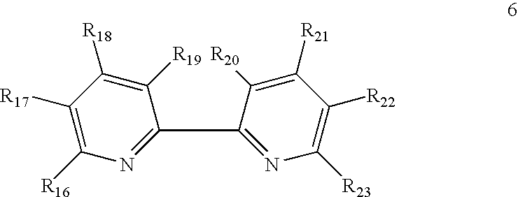
- R16, R17, R18, R19, R20, R21, R22 and R23 are independently —H, —F, —Cl, —Br, —I, —NO2, —CN, —CO2H, —SO3H, —NHNH2, —SH, aryl, alkoxycarbonyl, alkylaminocarbonyl, dialkylaminocarbonyl, —OH, alkoxy, —NH2, alkylamino, dialkylamino, alkanoylamino, arylcarboxamido, hydrazino, alkylhydrazino, hydroxylamino, alkoxylamino, alkylthio, alkenyl, or alkyl. Typically, the alkyl and alkoxy portions are C1 to C12. The alkyl or aryl portions of any of the substituents are optionally substituted by —F, —Cl, —Br, —I, alkylamino, dialkylamino, trialkylammonium (except on aryl portions), alkoxy, alkylthio, aryl, or a reactive group.
- Specific examples of suitable combinations of R16, R17, R18, R19, R20, R21, R22 and R23 include R16 and R23 as H or methyl; R17 and R22 as the same and —H or methyl; and R19 and R20 as the same and —H or methyl. An alternative combination is where one or more adjacent pairs of substituents R16 and R17, on the one hand, and R22 and R23, on the other hand, independently form a saturated or unsaturated 5- or 6-membered ring. Another combination includes R19 and R20 forming a saturated or unsaturated five or six membered ring.
- Another combination includes R16, R17, R19, R20, R22 and R23 as the same and —H and R18 and R21 as independently —H, alkoxy, —NH2, alkylamino, dialkylamino, alkylthio, alkenyl, or alkyl. The alkyl or aryl portions of any of the substituents are optionally substituted by —F, —Cl, —Br, —I, alkylamino, dialkylamino, trialkylammonium (except on aryl portions), alkoxy, alkylthio, aryl, or a reactive group. As an example, R18 and R21 can be the same or different and are —H, C1-C6 alkyl, C1-C6 amino, C1 to C12 alkylamino, C2 to C12 dialkylamino, C1 to C12 alkylthio, or C1 to C12 alkoxy, the alkyl portions of any of the substituents are optionally substituted by a —F, —Cl, —Br, —I, aryl, C2 to C12 dialkylamino, C3 to C18 trialkylammonium, C1 to C6 alkoxy, C1 to C6 alkylthio or a reactive group.
- Examples of suitable terdentate ligands include, but are not limited to, diethylenetriamine, 2,2′,2″-terpyridine, 2,6-bis(N-pyrazolyl)pyridine, and derivatives of these compounds. 2,2′,2″-terpyridine and 2,6-bis(N-pyrazolyl)pyridine have the following
general formulas 7 and 8 respectively: -

- With regard to formula 7, R24, R25 and R26 are independently —H or substituted or unsubstituted C1 to C12 alkyl. Typically, R24, R25 and R26 are —H or methyl and, in some embodiments, R24 and R26 are the same and are —H. Other substituents at these or other positions of the compounds of
formulas 7 and 8 can be added. - With regard to
formula 8, R27, R28 and R29 are independently —H, —F, —Cl, —Br, —I, —NO2, —CN, —CO2H, —SO3H, —NHNH2, —SH, alkoxycarbonyl, alkylaminocarbonyl, dialkylaminocarbonyl, —OH, alkoxy, —NH2, alkylamino, dialkylamino, alkanoylamino, arylcarboxamido, hydrazino, alkylhydrazino, hydroxylamino, alkoxylamino, alkylthio, alkenyl, aryl, or alkyl. The alkyl or aryl portions of any of the substituents are optionally substituted by —F, —Cl, —Br, —I, alkylamino, dialkylamino, trialkylammonium (except on aryl portions), alkoxy, alkylthio, aryl, or a reactive group. Typically, the alkyl and alkoxy groups are C1 to C12 and, in some embodiments, R27 and R29 are the same and are —H. - Examples of suitable tetradentate ligands include, but are not limited to, triethylenetriamine, ethylenediaminediacetic acid, tetraaza macrocycles and similar compounds as well as derivatives thereof.
- Examples of suitable transition metal complexes are illustrated using Formula 9 and 10:
-

- With regard to transition metal complexes of formula 9, the metal osmium is complexed to two substituted 2,2′-biimidazole ligands and one substituted or unsubstituted 2,2′-bipyridine ligand. R1, R2, R3, R4, R5, R6, R16, R17, R18, R19, R20, R21, R22, R23, c, d, and X are the same as described above.
- In one embodiment, R1 and R2 are methyl; R3, R4, R5, R6, R16, R17, R19, R20, R22 and R23 are —H; and R18 and R21 are the same and are —H, methyl, or methoxy. In an embodiment of an embodiment of the invention, R18 and R21 are methyl or methoxy.
- In another embodiment, R1 and R2 are methyl; R3, R4, R5, R6, R16, R17, R18, R19, R20, R22 and R23 are —H; and R21 is halo, C1 to C12 alkoxy, C1 to C12 alkylamino, or C2 to C24 dialkylamino. The alkyl or aryl portions of any of the substituents are optionally substituted by —F, —Cl, —Br, —I, alkylamino, dialkylamino, trialkylammonium (except on aryl portions), alkoxy, alkylthio, aryl, or a reactive group. For example, R21 is a C1 to C12 alkylamino or C2 to C24 dialkylamino, the alkyl portion(s) of which are substituted with a reactive group, such as a carboxylic acid, activated ester, or amine. Typically, the alkylamino group has 1 to 6 carbon atoms and the dialkylamino group has 2 to 8 carbon atoms.
- With regard to transition metal complexes of
formula 10, the metal osmium is complexed to two substituted 2,2′-biimidazole ligands and one substituted or unsubstituted 2-(2-pyridyl)imidazole ligand. R1, R2, R3, R4, R5, R6, R′1, R′3, R′4, Ra, Rb, Rc, Rd, c, d, and X are the same as described above. - In one embodiment, R1 and R2 are methyl; R3, R4, R5, R6, R′3, R′4 and Rd are independently —H or methyl; Ra and Rc are the same and are —H; and Rb is C1 to C12 alkoxy, C1 to C12 alkylamino, or C2 to C24 dialkylamino. The alkyl or aryl portions of any of the substituents are optionally substituted by —F, —Cl, —Br, —I, alkylamino, dialkylamino, trialkylammonium (except on aryl portions), alkoxy, alkylthio, aryl, or a reactive group.
- A list of specific examples of preferred transition metal complexes with respective redox potentials is shown in Table 1.
-
TABLE 1 Redox Potentials of Selected Transition Metal Complexes E1/2 (vs Ag/ Complex Structure AgCl)/mV* I 
−110 II 
−100 III 
128 IV 
−86 V 
−97 VI 
−120 VII 
32 VIII 
−100 IX 
−93 X 
−125 XI 
−60 XII 
−74 XIII 
−97 IVX 
−81 VX 
−230 *Redox potentials were estimated by averaging the positions of the reduction wave peaks and the oxidation wave peaks of cyclic voltammograms (CVs) obtained in pH 7 PBS buffer with a glassy carbon working electrode, a graphite counter electrode and a standard Ag/AgCl reference electrode at a sweep rate of 50 mV/s. - The transition metal complexes of Formula I also include transition metal complexes that are coupled to a polymeric backbone through one or more of L, L1, L2, L3, and L4. Additional examples of suitable transition metal complexes are described in U.S. patent application Ser. No. 09/712,065, entitled “Polymeric Transition Metal Complexes and Uses Thereof”, incorporated herein by reference. In some embodiments, the polymeric backbone has functional groups that act as ligands of the transitional metal complex. Such polymeric backbones include, for example, poly(4-vinylpyridine) and poly(N-vinylimidazole) in which the pyridine and imidazole groups, respectively, can act as monodentate ligands of the transition metal complex.
- The polymeric backbone has the following general formula, where n may be 2, n′ may be 17, and n″ may be 1:
-

- In other embodiments, the transition metal complex of the redox polymers of an embodiment of the invention can be the reaction product between a reactive group on a precursor polymer and a reactive group on a ligand of a precursor transition metal complex (such as a complex of Formula I where one of L, L1, L2, L3 and L4 includes a reactive group as described above). Suitable precursor polymers include, for example, poly(acrylic acid) (Formula 11), styrene/maleic anhydride copolymer (Formula 12), methylvinylether/maleic anhydride copolymer (GANTREX polymer) (Formula 13), poly(vinylbenzylchloride) (Formula 14), poly(allylamine) (Formula 15), polylysine (Formula 16), carboxy-poly(vinylpyridine (Formula 17), and poly(sodium 4-styrene sulfonate) (Formula 18).
-


- Alternatively, the transition metal complex can have reactive group(s) for immobilization or conjugation of the complexes to other substrates or carriers, examples of which include, but are not limited to, macromolecules (e.g., enzymes) and surfaces (e.g., electrode surfaces).
- For reactive attachment to polymers, substrates, or other carriers, the transition metal complex precursor includes at least one reactive group that reacts with a reactive group on the polymer, substrate, or carrier. Typically, covalent bonds are formed between the two reactive groups to generate a linkage. Examples of such linkages are provided in Table 2, below. Generally, one of the reactive groups is an electrophile and the other reactive group is a nucleophile.
-
TABLE 2 Examples of Reactive Group Linkages First Reactive Group Second Reactive Group Resulting Linkage Activated ester* Amine Carboxamide Acrylamide Thiol Thioether Acyl azide Amine Carboxamide Acyl halide Amine Carboxamide Carboxylic acid Amine Carboxamide Aldehyde or ketone Hydrazine Hydrazone Aldehyde or ketone Hydroxyamine Oxime Alkyl halide Amine Alkylamine Alkyl halide Carboxylic acid Carboxylic ester Alkyl halide Imidazole Imidazolium Alkyl halide Pyridine Pyridinium Alkyl halide Alcohol/phenol Ether Alkyl halide Thiol Thioether Alkyl sulfonate Thiol Thioether Alkyl sulfonate Pyridine Pyridinium Alkyl sulfonate Imidazole Imidazolium Alkyl sulfonate Alcohol/phenol Ether Anhydride Alcohol/phenol Ester Anhydride Amine Carboxamide Aziridine Thiol Thioether Aziridine Amine Alkylamine Aziridine Pyridine Pyridinium Epoxide Thiol Thioether Epoxide Amine Alkylamine Epoxide Pyridine Pyridinium Halotriazine Amine Aminotriazine Halotriazine Alcohol Triazinyl ether Imido ester Amine Amidine Isocyanate Amine Urea Isocyanate Alcohol Urethane Isothiocyanate Amine Thiourea Maleimide Thiol Thioether Sulfonyl halide Amine Sulfonamide *Activated esters, as understood in the art, generally include esters of succinimidyl, benzotriazolyl, or aryl substituted by electron-withdrawing groups such as sulfo, nitro, cyano, or halo; or carboxylic acids activated by carbodiimides. - Transition metal complexes used in the redox polymers of embodiments of an embodiment of the invention can be soluble in water or other aqueous solutions, or in organic solvents. In general, transition metal complexes can be made soluble in either aqueous or organic solvents by having an appropriate counter ion or ions, X. For example, transition metal complexes with small counter anions, such as F−, Cl−, and Br−, tend to be water soluble. On the other hand, transition metal complexes with bulky counter anions, such as I−, BF4 − and PF6 −, tend to be soluble in organic solvents. In an embodiment of an embodiment of the invention, the solubility of transition metal complexes of aspects of an embodiment of the invention is greater than about 0.1 M (moles/liter) at 25° C. for a desired solvent.
- The use of transition metal complexes as redox mediators is described, for example, in U.S. Pat. Nos. 5,262,035; 5,262,305; 5,320,725; 5,365,786; 5,593,852; 5,665,222; 5,972,199; and 6,143,164 and U.S. patent application Ser. Nos. 09/034,372, (now U.S. Pat. No. 6,134,461); 09/070,677, (now U.S. Pat. No. 6,175,752); 09/295,962, (now U.S. Pat. No. 6,338,790) and 09/434,026, all of which are herein incorporated by reference. The transitional metal complexes described herein can typically be used in place of those discussed in the references listed above.
- Redox Polymers
- Suitable redox polymers for use with the electrochemical analyte sensors may comprise, inter alia, a transition metal complex, a cross-linker and a polymeric backbone. Such redox polymers are useful as redox mediators in electrochemical biosensors for the detection of analytes in biofluids, for example. In some aspects the redox polymers may include coordination complexes including an osmium.
- In general, the redox polymer is disposed on or in proximity to (e.g., in a solution surrounding) a working electrode. The redox polymer transfers electrons between the working electrode and an analyte. In some preferred embodiments, an enzyme is also included to facilitate the transfer. For example, the redox polymer transfers electrons between the working electrode and glucose (typically via an enzyme) in an enzyme-catalyzed reaction of glucose. Redox polymers are particularly useful for forming non-leachable coatings on the working electrode. These can be formed, for example, by crosslinking the redox polymer on the working electrode, or by cross-linking the redox polymer and the enzyme on the working electrode.
- Transition metal complexes can enable accurate, reproducible and quick or continuous assays. Transition metal complex redox mediators accept electrons from, or transfer electrons to, enzymes or analytes at a high rate and also exchange electrons rapidly with an electrode. Typically, the rate of self exchange, the process in which a reduced redox mediator transfers an electron to an oxidized redox mediator, is rapid. At a defined redox mediator concentration, this provides for more rapid transport of electrons between the enzyme (or analyte) and electrode, and thereby shortens the response time of the sensor. Additionally, the transition metal complex redox mediators disclosed herein are typically stable under ambient light and at the temperatures encountered in use, storage and transportation. In an embodiment of an embodiment of the invention, the transition metal complex redox mediators do not undergo chemical change, other than oxidation and reduction, in the period of use or under the conditions of storage, though the redox mediators can be designed to be activated by reacting, for example, with water or the analyte.
- A transition metal complex can be used as a redox mediator in combination with a redox enzyme to electrooxidize or electroreduce the analyte or a compound derived of the analyte, for example by hydrolysis of the analyte. The redox potentials of the redox mediators are generally more positive (i.e. more oxidizing) than the redox potentials of the redox enzymes when the analyte is electrooxidized and more negative when the analyte is electroreduced. For example, the redox potentials of the preferred transition metal complex redox mediators used for electrooxidizing glucose with an analyte response dehydrogenase optionally complexed with a co-factor, such as GDH optionally complexed with a co-factor such as FAD, is between about −200 mV and +200 mV versus a Ag/AgCl reference electrode, and the most preferred mediators have redox potentials between about −100 mV and about +100 mV versus a Ag/AgCl reference electrode.
- Crosslinked Transition Metal Complex Polymers
- Electron transport involves an exchange of electrons between segments of the redox polymers (e.g., one or more transition metal complexes coupled to a polymeric backbone, as described above) in a crosslinked film disposed on an electrode. A transition metal complex can be bound to the polymer backbone though covalent, coordinative or ionic bonds, where covalent and coordinative binding are preferred. Electron exchange occurs, for example, through the collision of different segments of the crosslinked redox polymer. Electrons transported through the redox polymer can originate from, for example, electrooxidation or electroreduction of an enzymatic substrate, such as, for example, the oxidation of glucose by an analyte response dehydrogenase optionally complexed with a co-factor, such as glucose dehydrogenase.
- The degree of crosslinking of the redox polymer can influence the transport of electrons or ions and thereby the rates of the electrochemical reactions. Excessive crosslinking of the polymer can reduce the mobility of the segments of the redox polymer. A reduction in segment mobility can slow the diffusion of electrons or ions through the redox polymer film. A reduction in the diffusivity of electrons, for example, can require a concomitant reduction in the thickness of the film on the electrode where electrons or electron vacancies are collected or delivered. The degree of crosslinking in a redox polymer film can thus affect the transport of electrons from, for example, an enzyme to the transition metal redox centers of the redox polymer such as, for example, Os2+/3+ metal redox centers; between redox centers of the redox polymer; and from these transition metal redox centers to the electrode.
- Inadequate crosslinking of a redox polymer can result in excessive swelling of the redox polymer film and to the leaching of the components of the redox polymer film. Excessive swelling can also result in the migration of the swollen polymer into the analyzed solution, in the softening of the redox polymer film, in the film's susceptibility to removal by shear, or any combination of these effects.
- Crosslinking can decrease the leaching of film components and can improve the mechanical stability of the film under shear stress. For example, as disclosed in Binyamin, G. and Heller, A; Stabilization of Wired Glucose Oxidase Anodes Rotating at 1000 rpm at 37° C.; Journal of the Electrochemical Society, 146(8), 2965-2967, 1999, herein incorporated by reference, replacing a difunctional cross-linker, such as polyethylene glycol diglycidyl ether, with a trifunctional cross-linker such as N,N-diglycidyl-4-glycidyloxyaniline, for example, can reduce leaching and shear problems associated with inadequate crosslinking.
- Examples of other bifunctional, trifunctional and tetrafunctional cross-linkers are listed below:
-

- Alternatively, the number of crosslinking sites can be increased by reducing the number of transition metal complexes attached to the polymeric backbone, thus making more polymer pendant groups available for crosslinking. One important advantage of at least some of the redox polymers is the increased mobility of the pendant transition metal complexes, resulting from the flexibility of the pendant groups. As a result, in at least some embodiments, fewer transition metal complexes per polymer backbone are needed to achieve a desired level of diffusivity of electrons and current density of analyte electrooxidation or electroreduction.
- Coordination in Transition Metal Complex Polymers
- Transition metal complexes can be directly or indirectly attached to a polymeric backbone, depending on the availability and nature of the reactive groups on the complex and the polymeric backbone. For example, the pyridine groups in poly(4-vinylpyridine) or the imidazole groups in poly(N-vinylimidazole) are capable of acting as monodentate ligands and thus can be attached to a metal center directly. Alternatively, the pyridine groups in poly(4-vinylpyridine) or the imidazole groups in poly(N-vinylimidazole) can be quaternized with a substituted alkyl moiety having a suitable reactive group, such as a carboxylate function, that can be activated to form a covalent bond with a reactive group, such as an amine, of the transition metal complex. (See Table 2 for a list of other examples of reactive groups).
- Redox centers such as, for example, Os2+/3+ can be coordinated with five heterocyclic nitrogens and an additional ligand such as, for example, a chloride anion. An example of such a coordination complex includes two bipyridine ligands which form stable coordinative bonds, the pyridine of poly(4-vinylpyridine) which forms a weaker coordinative bond, and a chloride anion which forms the least stable coordinative bond.
- Alternatively, redox centers, such as Os2+/3+, can be coordinated with six heterocyclic nitrogen atoms in its inner coordination sphere. In an embodiment of an embodiment of the invention the six coordinating atoms are paired in the ligands, for example, each ligand is composed of at least two rings. Pairing of the coordinating atoms can influence the potential of an electrode used in conjunction with redox polymers of embodiments of an embodiment of the invention.
- Typically, for analysis of glucose, the potential at which the working electrode, coated with the redox polymer, is poised is negative of about +250 mV vs. SCE (standard calomel electrode). In an embodiment of an embodiment of the invention, the electrode is poised negative of about +150 mV vs. SCE. Poising the electrode at these potentials reduces the interfering electrooxidation of constituents of biological solutions such as, for example, urate, ascorbate and acetaminophen. The potential can be modified by altering the ligand structure of the complex.
- The redox potential of a redox polymer, as described herein, is related to the potential at which the electrode is poised. Selection of a redox polymer with a desired redox potential allows tuning of the potential at which the electrode is best poised. The redox potentials of a number of the redox polymers described herein are negative of about +150 mV vs. SCE and can be negative of about +50 mV vs. SCE to allow the poising of the electrode potentials negative of about +250 mV vs. SCE and in an embodiment of an embodiment of the invention negative of about +150 mV vs. SCE.
- The strength of the coordination bond can influence the potential of the redox centers in the redox polymers. Typically, the stronger the coordinative bond, the more positive the redox potential. A shift in the potential of a redox center resulting from a change in the coordination sphere of the transition metal can produce a labile transition metal complex. For example, when the redox potential of an Os2+/3+ complex is downshifted by changing the coordination sphere, the complex becomes labile. Such a labile transition metal complex may be undesirable when fashioning a metal complex polymer for use as a redox mediator and can be avoided through the use of weakly coordinating multidentate or chelating heterocyclics as ligands.
- Electrode Interference
- Transition metal complexes used as redox mediators in electrodes can be affected by the presence of transition metals in the analyzed sample including, for example, Fe3+ or Zn2+. The addition of a transition metal cation to a buffer used to test an electrode results in a decline in the current produced. The degree of current decline depends on the presence of anions in the buffer which precipitate the transition metal cations. The lesser the residual concentration of transition metal cations in the sample solution, the more stable the current. Anions which aid in the precipitation of transition metal cations include, for example, phosphate. It has been found that a decline in current upon the addition of transition metal cations is most pronounced in non-phosphate buffers. If an electrode is transferred from a buffer containing a transition metal cation to a buffer substantially free of the transition metal cation, the original current is restored.
- The decline in current is thought to be due to additional crosslinking of a pyridine-containing polymer backbone produced by the transition metal cations. The transition metal cations can coordinate nitrogen atoms of different chains and chain segments of the polymers. Coordinative crosslinking of nitrogen atoms of different chain segments by transition metal cations can reduce the diffusivity of electrons.
- Serum and other physiological fluids contain traces of transition metal ions, which can diffuse into the films of electrodes made with the redox polymers of embodiments of an embodiment of the invention, lowering the diffusivity of electrons and thereby the highest current reached at high analyte concentration. In addition, transition metal ions like iron and copper can bind to proteins of enzymes and to the reaction centers or channels of enzymes, reducing their turnover rate. The resulting decrease in sensitivity can be remedied through the use of anions which complex with interfering transition metal ions, for example, in a buffer employed during the production of the transition metal complex. A non-cyclic polyphosphate such as, for example, pyrophosphate or triphosphate, can be used. For example, sodium or potassium non-cyclic polyphosphate buffers can be used to exchange phosphate anions for those anions in the transition metal complex which do not precipitate transition metal ions. The use of linear phosphates can alleviate the decrease in sensitivity by forming strong complexes with the damaging transition metal ions, assuring that their activity will be low. Other complexing agents can also be used as long as they are not electrooxidized or electroreduced at the potential at which the electrode is poised.
- Generally, embodiments of the invention relate to methods and devices for detecting at least one analyte, such as glucose, in body fluid. Embodiments relate to the continuous and/or automatic in vivo monitoring of the level of one or more analytes using a continuous analyte monitoring system that includes an analyte sensor at least a portion of which is to be positioned beneath a skin surface of a user for a period of time and/or the discrete monitoring of one or more analytes using an in vitro blood glucose (“BG”) meter and an analyte test strip. Embodiments include combined or combinedable devices, systems and methods and/or transferring data between an in vivo continuous system and a BG meter system.
- An electrochemical sensor that includes the analyte-responsive dehydrogenase and optional co-factor can be formed on a substrate. The sensor may also include at least one counter electrode (or counter/reference electrode) and/or at least one reference electrode. An “electrochemical sensor” is a device configured to detect the presence and/or measure the level of an analyte in a sample, via an electrochemical oxidation or reduction reaction on the sensor, or via a sequence of chemical reactions where at least one of the chemical reactions is an electrochemical oxidation or reduction reactions on the sensor. These reactions are transduced to an electrical signal that can be correlated to an amount, concentration, or level of an analyte in the sample.
- Accordingly, embodiments include analyte monitoring devices and systems that include an analyte sensor—at least a portion of which is positionable beneath the skin of the user—for the in vivo detection, of an analyte, such as glucose, lactate, and the like, in a body fluid. Embodiments include wholly implantable analyte sensors and analyte sensors in which only a portion of the sensor is positioned under the skin and a portion of the sensor resides above the skin, e.g., for contact to a transmitter, receiver, transceiver, processor, etc. The sensor may be, for example, subcutaneously positionable in a patient for the continuous or periodic monitoring of a level of an analyte in a patient's interstitial fluid. For the purposes of this description, continuous monitoring and periodic monitoring will be used interchangeably, unless noted otherwise. The sensor response may be correlated and/or converted to analyte levels in blood or other fluids. In certain embodiments, an analyte sensor may be positioned in contact with interstitial fluid to detect the level of glucose, which detected glucose may be used to infer the glucose level in the patient's bloodstream. Analyte sensors may be insertable into a vein, artery, or other portion of the body containing fluid. Embodiments of the analyte sensors described herein having an analyte-responsive dehydrogenase and optional co-factor may be configured for monitoring the level of the analyte over a time period which may range from minutes, hours, days, weeks, to months, or longer.
- Of interest are analyte sensors, such as glucose sensors, having the analyte-responsive dehydrogenase and optional co-factor, that are capable of in vivo detection of an analyte for about one hour or more, e.g., about a few hours or more, e.g., about a few days of more, e.g., about three or more days, e.g., about five days or more, e.g., about seven days or more, e.g., about several weeks or at least one month or more. Future analyte levels may be predicted based on information obtained, e.g., the current analyte level at time to, the rate of change of the analyte, etc. Predictive alarms may notify the user of a predicted analyte levels that may be of concern in advance of the user's analyte level reaching the future level. This provides the user an opportunity to take corrective action.
-
FIG. 1 shows a data monitoring and management system such as, for example, an analyte (e.g., glucose)monitoring system 100 in accordance with certain embodiments. Embodiments of the subject invention are further described primarily with respect to glucose monitoring devices and systems, and methods of glucose detection, for convenience only and such description is in no way intended to limit the scope of the invention. It is to be understood that the analyte monitoring system may be configured to monitor a variety of analytes at the same time or at different times. - Analytes that may be monitored include, but are not limited to, acetyl choline, amylase, bilirubin, cholesterol, chorionic gonadotropin, creatine kinase (e.g., CK-MB), creatine, creatinine, DNA, fructosamine, glucose, glutamine, growth hormones, hormones, ketone bodies, lactate, peroxide, prostate-specific antigen, prothrombin, RNA, thyroid stimulating hormone, and troponin. The concentration of drugs, such as, for example, antibiotics (e.g., gentamicin, vancomycin, and the like), digitoxin, digoxin, drugs of abuse, theophylline, and warfarin, may also be monitored. In those embodiments that monitor more than one analyte, the analytes may be monitored at the same or different times.
- The
analyte monitoring system 100 includes asensor 101, adata processing unit 102 connectable to thesensor 101, and aprimary receiver unit 104 which is configured to communicate with thedata processing unit 102 via acommunication link 103. In certain embodiments, theprimary receiver unit 104 may be further configured to transmit data to adata processing terminal 105 to evaluate or otherwise process or format data received by theprimary receiver unit 104. Thedata processing terminal 105 may be configured to receive data directly from thedata processing unit 102 via a communication link which may optionally be configured for bidirectional communication. Further, thedata processing unit 102 may include a transmitter or a transceiver to transmit and/or receive data to and/or from theprimary receiver unit 104 and/or thedata processing terminal 105 and/or optionally thesecondary receiver unit 106. - Also shown in
FIG. 1 is an optionalsecondary receiver unit 106 which is operatively coupled to the communication link and configured to receive data transmitted from thedata processing unit 102. Thesecondary receiver unit 106 may be configured to communicate with theprimary receiver unit 104, as well as thedata processing terminal 105. Thesecondary receiver unit 106 may be configured for bidirectional wireless communication with each of theprimary receiver unit 104 and thedata processing terminal 105. As discussed in further detail below, in certain embodiments thesecondary receiver unit 106 may be a de-featured receiver as compared to the primary receiver, i.e., the secondary receiver may include a limited or minimal number of functions and features as compared with theprimary receiver unit 104. As such, thesecondary receiver unit 106 may include a smaller (in one or more, including all, dimensions), compact housing or embodied in a device such as a wrist watch, arm band, etc., for example. Alternatively, thesecondary receiver unit 106 may be configured with the same or substantially similar functions and features as theprimary receiver unit 104. Thesecondary receiver unit 106 may include a docking portion to be mated with a docking cradle unit for placement by, e.g., the bedside for night time monitoring, and/or a bi-directional communication device. A docking cradle may recharge a powers supply. - Only one
sensor 101,data processing unit 102 anddata processing terminal 105 are shown in the embodiment of theanalyte monitoring system 100 illustrated inFIG. 1 . However, it will be appreciated by one of ordinary skill in the art that theanalyte monitoring system 100 may include more than onesensor 101 and/or more than onedata processing unit 102, and/or more than onedata processing terminal 105. Multiple sensors may be positioned in a patient for analyte monitoring at the same or different times. In certain embodiments, analyte information obtained by a first positioned sensor may be employed as a comparison to analyte information obtained by a second sensor. This may be useful to confirm or validate analyte information obtained from one or both of the sensors. Such redundancy may be useful if analyte information is contemplated in critical therapy-related decisions. In certain embodiments, a first sensor may be used to calibrate a second sensor. - The
analyte monitoring system 100 may be a continuous monitoring system, or semi-continuous, or a discrete monitoring system. In a multi-component environment, each component may be configured to be uniquely identified by one or more of the other components in the system so that communication conflict may be readily resolved between the various components within theanalyte monitoring system 100. For example, unique IDs, communication channels, and the like, may be used. - In certain embodiments, the
sensor 101 is physically positioned in or on the body of a user whose analyte level is being monitored. Thesensor 101 may be configured to at least periodically sample the analyte level of the user and convert the sampled analyte level into a corresponding signal for transmission by thedata processing unit 102. Thedata processing unit 102 is coupleable to thesensor 101 so that both devices are positioned in or on the user's body, with at least a portion of theanalyte sensor 101 positioned transcutaneously. The data processing unit may include a fixation element such as adhesive or the like to secure it to the user's body. A mount (not shown) attachable to the user and mateable with theunit 102 may be used. For example, a mount may include an adhesive surface. Thedata processing unit 102 performs data processing functions, where such functions may include but are not limited to, filtering and encoding of data signals, each of which corresponds to a sampled analyte level of the user, for transmission to theprimary receiver unit 104 via thecommunication link 103. In one embodiment, thesensor 101 or thedata processing unit 102 or a combined sensor/data processing unit may be wholly implantable under the skin layer of the user. - In certain embodiments, the
primary receiver unit 104 may include an analog interface section including and RF receiver and an antenna that is configured to communicate with thedata processing unit 102 via thecommunication link 103, and a data processing section for processing the received data from thedata processing unit 102 such as data decoding, error detection and correction, data clock generation, data bit recovery, etc., or any combination thereof. - In operation, the
primary receiver unit 104 in certain embodiments is configured to synchronize with thedata processing unit 102 to uniquely identify thedata processing unit 102, based on, for example, an identification information of thedata processing unit 102, and thereafter, to periodically receive signals transmitted from thedata processing unit 102 associated with the monitored analyte levels detected by thesensor 101. - Referring again to
FIG. 1 , thedata processing terminal 105 may include a personal computer, a portable computer such as a laptop or a handheld device (e.g., personal digital assistants (PDAs), telephone such as a cellular phone (e.g., a multimedia and Internet-enabled mobile phone such as an iPhone™ or similar phone), mp 3 player, pager, and the like), drug delivery device, each of which may be configured for data communication with the receiver via a wired or a wireless connection. Additionally, thedata processing terminal 105 may further be connected to a data network (not shown) for storing, retrieving, updating, and/or analyzing data corresponding to the detected analyte level of the user. - The
data processing terminal 105 may include an infusion device such as an insulin infusion pump or the like, which may be configured to administer insulin to patients, and which may be configured to communicate with theprimary receiver unit 104 for receiving, among others, the measured analyte level. Alternatively, theprimary receiver unit 104 may be configured to integrate an infusion device therein so that theprimary receiver unit 104 is configured to administer insulin (or other appropriate drug) therapy to patients, for example, for administering and modifying basal profiles, as well as for determining appropriate boluses for administration based on, among others, the detected analyte levels received from thedata processing unit 102. An infusion device may be an external device or an internal device (wholly implantable in a user). - In certain embodiments, the
data processing terminal 105, which may include an insulin pump, may be configured to receive the analyte signals from thedata processing unit 102, and thus, incorporate the functions of theprimary receiver unit 104 including data processing for managing the patient's insulin therapy and analyte monitoring. In certain embodiments, thecommunication link 103 as well as one or more of the other communication interfaces shown inFIG. 1 , may use one or more of: an RF communication protocol, an infrared communication protocol, a Bluetooth enabled communication protocol, an 802.11x wireless communication protocol, or an equivalent wireless communication protocol which would allow secure, wireless communication of several units (for example, per HIPPA requirements), while avoiding potential data collision and interference. -
FIG. 2 shows a block diagram of an embodiment of a data processing unit of the data monitoring and detection system shown inFIG. 1 . User input and/or interface components may be included or a data processing unit may be free of user input and/or interface components. In certain embodiments, one or more application-specific integrated circuits (ASIC) may be used to implement one or more functions or routins associated with the operations of the data processing unit (and/or receiver unit) using for example one or more state machines and buffers. - As can be seen in the embodiment of
FIG. 2 , the sensor unit 101 (FIG. 1 ) includes four contacts, three of which are electrodes—work electrode (W) 210, reference electrode (R) 212, and counter electrode (C) 213, each operatively coupled to theanalog interface 201 of thedata processing unit 102. This embodiment also shows optional guard contact (G) 211. Fewer or greater electrodes may be employed. For example, the counter and reference electrode functions may be served by a single counter/reference electrode, there may be more than one working electrode and/or reference electrode and/or counter electrode, etc. -
FIG. 3 is a block diagram of an embodiment of a receiver/monitor unit such as theprimary receiver unit 104 of the data monitoring and management system shown inFIG. 1 . Theprimary receiver unit 104 includes one or more of: a blood glucosetest strip interface 301, anRF receiver 302, aninput 303, atemperature detection section 304, and aclock 305, each of which is operatively coupled to a processing andstorage section 307. Theprimary receiver unit 104 also includes a power supply 306 operatively coupled to a power conversion andmonitoring section 308. Further, the power conversion andmonitoring section 308 is also coupled to thereceiver processor 307. Moreover, also shown are a receiverserial communication section 309, and anoutput 310, each operatively coupled to the processing andstorage unit 307. The receiver may include user input and/or interface components or may be free of user input and/or interface components. - In certain embodiments, the
test strip interface 301 includes a glucose level testing portion to receive a blood (or other body fluid sample) glucose test or information related thereto. For example, the interface may include a test strip port to receive a glucose test strip. The device may determine the glucose level of the test strip, and optionally display (or otherwise notice) the glucose level on theoutput 310 of theprimary receiver unit 104. Any suitable test strip may be employed, e.g., test strips that only require a very small amount (e.g., one microliter or less, e.g., 0.5 microliter or less, e.g., 0.1 microliter or less), of applied sample to the strip in order to obtain accurate glucose information, e.g. FreeStyle® blood glucose test strips from Abbott Diabetes Care, Inc. Glucose information obtained by the in vitro glucose testing device may be used for a variety of purposes, computations, etc. For example, the information may be used to calibratesensor 101, confirm results of thesensor 101 to increase the confidence thereof (e.g., in instances in which information obtained bysensor 101 is employed in therapy related decisions), etc. - In further embodiments, the
data processing unit 102 and/or theprimary receiver unit 104 and/or thesecondary receiver unit 105, and/or the data processing terminal/infusion section 105 may be configured to receive the blood glucose value wirelessly over a communication link from, for example, a blood glucose meter. In further embodiments, a user manipulating or using the analyte monitoring system 100 (FIG. 1 ) may manually input the blood glucose value using, for example, a user interface (for example, a keyboard, keypad, voice commands, and the like) incorporated in the one or more of thedata processing unit 102, theprimary receiver unit 104,secondary receiver unit 105, or the data processing terminal/infusion section 105. - Additional detailed descriptions are provided in U.S. Pat. Nos. 5,262,035; 5,264,104; 5,262,305; 5,320,715; 5,593,852; 6,175,752; 6,650,471; 6,746,582, and in application Ser. No. 10/745,878 filed Dec. 26, 2003 entitled “Continuous Glucose Monitoring System and Methods of Use”, each of which is incorporated herein by reference.
-
FIG. 4 schematically shows an embodiment of an analyte sensor in accordance with the embodiments of the invention. This sensor embodiment includeselectrodes base 404. Electrodes (and/or other features) may be applied or otherwise processed using any suitable technology, e.g., chemical vapor deposition (CVD), physical vapor deposition, sputtering, reactive sputtering, printing, coating, ablating (e.g., laser ablation), painting, dip coating, etching, and the like. Materials include but are not limited to aluminum, carbon (such as graphite), cobalt, copper, gallium, gold, indium, iridium, iron, lead, magnesium, mercury (as an amalgam), nickel, niobium, osmium, palladium, platinum, rhenium, rhodium, selenium, silicon (e.g., doped polycrystalline silicon), silver, tantalum, tin, titanium, tungsten, uranium, vanadium, zinc, zirconium, mixtures thereof, and alloys, oxides, or metallic compounds of these elements. - The sensor may be wholly implantable in a user or may be configured so that only a portion is positioned within (internal) a user and another portion outside (external) a user. For example, the
sensor 400 may include a portion positionable above a surface of theskin 410, and a portion positioned below the skin. In such embodiments, the external portion may include contacts (connected to respective electrodes of the second portion by traces) to connect to another device also external to the user such as a transmitter unit. While the embodiment ofFIG. 4 shows three electrodes side-by-side on the same surface ofbase 404, other configurations are contemplated, e.g., fewer or greater electrodes, some or all electrodes on different surfaces of the base or present on another base, some or all electrodes stacked together, electrodes of differing materials and dimensions, etc. -
FIG. 5A shows a perspective view of an embodiment of anelectrochemical analyte sensor 500 having a first portion (which in this embodiment may be characterized as a major portion) positionable above a surface of theskin 510, and a second portion (which in this embodiment may be characterized as a minor portion) that includes aninsertion tip 530 positionable below the skin, e.g., penetrating through the skin and into, e.g., thesubcutaneous space 520, in contact with the user's biofluid such as interstitial fluid. Contact portions of a workingelectrode 501, areference electrode 502, and acounter electrode 503 are positioned on the portion of thesensor 500 situated above theskin surface 510. Workingelectrode 501, areference electrode 502, and acounter electrode 503 are shown at the second section and particularly at theinsertion tip 530. Traces may be provided from the electrode at the tip to the contact, as shown inFIG. 5A . It is to be understood that greater or fewer electrodes may be provided on a sensor. For example, a sensor may include more than one working electrode and/or the counter and reference electrodes may be a single counter/reference electrode, etc. -
FIG. 5B shows a cross sectional view of a portion of thesensor 500 ofFIG. 5A . Theelectrodes sensor 500 as well as the substrate and the dielectric layers are provided in a layered configuration or construction. For example, as shown inFIG. 5B , in one aspect, the sensor 500 (such as thesensor unit 101FIG. 1 ), includes asubstrate layer 504, and afirst conducting layer 501 such as carbon, gold, etc., disposed on at least a portion of thesubstrate layer 504, and which may provide the working electrode. Also shown disposed on at least a portion of thefirst conducting layer 501 is asensing layer 508. - A first insulation layer such as a first
dielectric layer 505 is disposed or layered on at least a portion of thefirst conducting layer 501, and further, asecond conducting layer 509 may be disposed or stacked on top of at least a portion of the first insulation layer (or dielectric layer) 505. As shown inFIG. 5B , thesecond conducting layer 509 may provide thereference electrode 502, as described herein having an extended lifetime, which includes a layer of silver/silver chloride (Ag/AgCl). - A
second insulation layer 506 such as a dielectric layer in one embodiment may be disposed or layered on at least a portion of thesecond conducting layer 509. Further, athird conducting layer 503 may provide thecounter electrode 503. It may be disposed on at least a portion of thesecond insulation layer 506. Finally, a third insulation layer may be disposed or layered on at least a portion of thethird conducting layer 503. In this manner, thesensor 500 may be layered such that at least a portion of each of the conducting layers is separated by a respective insulation layer (for example, a dielectric layer). The embodiment ofFIGS. 5A and 5B show the layers having different lengths. Some or all of the layers may have the same or different lengths and/or widths. - In certain embodiments, some or all of the
electrodes substrate 504 in the layered construction as described above, or alternatively, may be provided in a co-planar manner such that two or more electrodes may be positioned on the same plane (e.g., side-by side (e.g., parallel) or angled relative to each other) on thesubstrate 504. For example, co-planar electrodes may include a suitable spacing there between and/or include dielectric material or insulation material disposed between the conducting layers/electrodes. Furthermore, in certain embodiments one or more of theelectrodes substrate 504. In such embodiments, contact pads may be one the same or different sides of the substrate. For example, an electrode may be on a first side and its respective contact may be on a second side, e.g., a trace connecting the electrode and the contact may traverse through the substrate. - As noted above, analyte sensors may include an analyte-responsive enzyme to provide a sensing component or sensing layer. Some analytes, such as oxygen, can be directly electrooxidized or electroreduced on a sensor, and more specifically at least on a working electrode of a sensor. Other analytes, such as glucose and lactate, require the presence of at least one electron transfer agent and/or at least one catalyst to facilitate the electrooxidation or electroreduction of the analyte. Catalysts may also be used for those analyte, such as oxygen, that can be directly electrooxidized or electroreduced on the working electrode. For these analytes, each working electrode includes a sensing layer (see for example sensing layer 408 of
FIG. 5B ) proximate to or on a surface of a working electrode. In many embodiments, a sensing layer is formed near or on only a small portion of at least a working electrode. - The sensing layer includes one or more components designed to facilitate the electrochemical oxidation or reduction of the analyte. The sensing layer may include, for example, a catalyst to catalyze a reaction of the analyte and produce a response at the working electrode, an electron transfer agent to transfer electrons between the analyte and the working electrode (or other component), or both.
- A variety of different sensing layer configurations may be used. In certain embodiments, the sensing layer is deposited on the conductive material of a working electrode. The sensing layer may extend beyond the conductive material of the working electrode. In some cases, the sensing layer may also extend over other electrodes, e.g., over the counter electrode and/or reference electrode (or counter/reference is provided).
- A sensing layer that is in direct contact with the working electrode may contain an electron transfer agent to transfer electrons directly or indirectly between the analyte and the working electrode, and/or a catalyst to facilitate a reaction of the analyte. For example, a glucose, lactate, or oxygen electrode may be formed having a sensing layer which contains a catalyst, such as glucose oxidase, lactate oxidase, or laccase, respectively, and an electron transfer agent that facilitates the electrooxidation of the glucose, lactate, or oxygen, respectively.
- In other embodiments the sensing layer is not deposited directly on the working electrode. Instead, the sensing layer 64 may be spaced apart from the working electrode, and separated from the working electrode, e.g., by a separation layer. A separation layer may include one or more membranes or films or a physical distance. In addition to separating the working electrode from the sensing layer the separation layer may also act as a mass transport limiting layer and/or an interferent eliminating layer and/or a biocompatible layer.
- In certain embodiments which include more than one working electrode, one or more of the working electrodes may not have a corresponding sensing layer, or may have a sensing layer which does not contain one or more components (e.g., an electron transfer agent and/or catalyst) needed to electrolyze the analyte. Thus, the signal at this working electrode may correspond to background signal which may be removed from the analyte signal obtained from one or more other working electrodes that are associated with fully-functional sensing layers by, for example, subtracting the signal.
- In certain embodiments, the sensing layer includes one or more electron transfer agents. Electron transfer agents that may be employed are electroreducible and electrooxidizable ions or molecules having redox potentials that are a few hundred millivolts above or below the redox potential of the standard calomel electrode (SCE). The electron transfer agent may be organic, organometallic, or inorganic. Examples of organic redox species are quinones and species that in their oxidized state have quinoid structures, such as Nile blue and indophenol. Examples of organometallic redox species are metallocenes such as ferrocene. Examples of inorganic redox species are hexacyanoferrate (III), ruthenium hexamine etc.
- In certain embodiments, electron transfer agents have structures or charges which prevent or substantially reduce the diffusional loss of the electron transfer agent during the period of time that the sample is being analyzed. For example, electron transfer agents include but are not limited to a redox species, e.g., bound to a polymer which can in turn be disposed on or near the working electrode. The bond between the redox species and the polymer may be covalent, coordinative, or ionic. Although any organic, organometallic or inorganic redox species may be bound to a polymer and used as an electron transfer agent, in certain embodiments the redox species is a transition metal compound or complex, e.g., osmium, ruthenium, iron, and cobalt compounds or complexes. It will be recognized that many redox species described for use with a polymeric component may also be used, without a polymeric component.
- One type of polymeric electron transfer agent contains a redox species covalently bound in a polymeric composition. An example of this type of mediator is poly(vinylferrocene). Another type of electron transfer agent contains an ionically-bound redox species. This type of mediator may include a charged polymer coupled to an oppositely charged redox species. Examples of this type of mediator include a negatively charged polymer coupled to a positively charged redox species such as an osmium or ruthenium polypyridyl cation. Another example of an ionically-bound mediator is a positively charged polymer such as quaternized poly(4-vinyl pyridine) or poly(1-vinyl imidazole) coupled to a negatively charged redox species such as ferricyanide or ferrocyanide. In other embodiments, electron transfer agents include a redox species coordinatively bound to a polymer. For example, the mediator may be formed by coordination of an osmium or
cobalt - Suitable electron transfer agents are osmium transition metal complexes with one or more ligands, each ligand having a nitrogen-containing heterocycle such as 2,2′-bipyridine, 1,10-phenanthroline, 1-methyl, 2-pyridyl biimidazole, or derivatives thereof. The electron transfer agents may also have one or more ligands covalently bound in a polymer, each ligand having at least one nitrogen-containing heterocycle, such as pyridine, imidazole, or derivatives thereof. One example of an electron transfer agent includes (a) a polymer or copolymer having pyridine or imidazole functional groups and (b) osmium cations complexed with two ligands, each ligand containing 2,2′-bipyridine, 1,10-phenanthroline, or derivatives thereof, the two ligands not necessarily being the same. Some derivatives of 2,2′-bipyridine for complexation with the osmium cation include but are not limited to 4,4′-dimethyl-2,2′-bipyridine and mono-, di-, and polyalkoxy-2,2′-bipyridines, such as 4,4′-dimethoxy-2,2′-bipyridine. Derivatives of 1,10-phenanthroline for complexation with the osmium cation include but are not limited to 4,7-dimethyl-1,10-phenanthroline and mono, di-, and polyalkoxy-1,10-phenanthrolines, such as 4,7-dimethoxy-1,10-phenanthroline. Polymers for complexation with the osmium cation include but are not limited to polymers and copolymers of poly(1-vinyl imidazole) (referred to as “PVI”) and poly(4-vinyl pyridine) (referred to as “PVP”). Suitable copolymer substituents of poly(1-vinyl imidazole) include acrylonitrile, acrylamide, and substituted or quaternized N-vinyl imidazole, e.g., electron transfer agents with osmium complexed to a polymer or copolymer of poly(1-vinyl imidazole).
- Embodiments may employ electron transfer agents having a redox potential ranging from about −200 mV to about +200 mV versus the standard calomel electrode (SCE). The sensing layer may also include a catalyst which is capable of catalyzing a reaction of the analyte. The catalyst may also, in some embodiments, act as an electron transfer agent. One example of a suitable catalyst is an enzyme which catalyzes a reaction of the analyte. For example, a catalyst, such as a glucose oxidase, glucose dehydrogenase (e.g., pyrroloquinoline quinone (PQQ), dependent glucose dehydrogenase, flavine adenine dinucleotide (FAD) dependent glucose dehydrogenase, or nicotinamide adenine dinucleotide (NAD) dependent glucose dehydrogenase), may be used when the analyte of interest is glucose. A lactate oxidase or lactate dehydrogenase may be used when the analyte of interest is lactate. Laccase may be used when the analyte of interest is oxygen or when oxygen is generated or consumed in response to a reaction of the analyte.
- The sensing layer may also include a catalyst which is capable of catalyzing a reaction of the analyte. The catalyst may also, in some embodiments, act as an electron transfer agent. One example of a suitable catalyst is an enzyme which catalyzes a reaction of the analyte. For example, a catalyst, such as a glucose oxidase, glucose dehydrogenase (e.g., pyrroloquinoline quinone (PQQ), dependent glucose dehydrogenase or oligosaccharide dehydrogenase, flavine adenine dinucleotide (FAD) dependent glucose dehydrogenase, nicotinamide adenine dinucleotide (NAD) dependent glucose dehydrogenase), may be used when the analyte of interest is glucose. A lactate oxidase or lactate dehydrogenase may be used when the analyte of interest is lactate. Laccase may be used when the analyte of interest is oxygen or when oxygen is generated or consumed in response to a reaction of the analyte.
- In certain embodiments, a catalyst may be attached to a polymer, cross linking the catalyst with another electron transfer agent (which, as described above, may be polymeric. A second catalyst may also be used in certain embodiments. This second catalyst may be used to catalyze a reaction of a product compound resulting from the catalyzed reaction of the analyte. The second catalyst may operate with an electron transfer agent to electrolyze the product compound to generate a signal at the working electrode. Alternatively, a second catalyst may be provided in an interferent-eliminating layer to catalyze reactions that remove interferents.
- Certain embodiments include a Wired Enzyme™ sensing layer (Abbott Diabetes Care) that works at a gentle oxidizing potential, e.g., a potential of about +40 mV vs. Ag/AgCl. This sensing layer uses an osmium (Os)-based mediator designed for low potential operation and is stably anchored in a polymeric layer. Accordingly, in certain embodiments the sensing element is redox active component that includes (1) Osmium-based mediator molecules attached by stable (bidente) ligands anchored to a polymeric backbone, and (2) glucose oxidase enzyme molecules. These two constituents are crosslinked together.
- A mass transport limiting layer (not shown), e.g., an analyte flux modulating layer, may be included with the sensor to act as a diffusion-limiting barrier to reduce the rate of mass transport of the analyte, for example, glucose or lactate, into the region around the working electrodes. The mass transport limiting layers are useful in limiting the flux of an analyte to a working electrode in an electrochemical sensor so that the sensor is linearly responsive over a large range of analyte concentrations and is easily calibrated. Mass transport limiting layers may include polymers and may be biocompatible. A mass transport limiting layer may provide many functions, e.g., biocompatibility and/or interferent-eliminating, etc.
- In certain embodiments, a mass transport limiting layer is a membrane composed of crosslinked polymers containing heterocyclic nitrogen groups, such as polymers of polyvinylpyridine and polyvinylimidazole. Embodiments also include membranes that are made of a polyurethane, or polyether urethane, or chemically related material, or membranes that are made of silicone, and the like.
- A membrane may be formed by crosslinking in situ a polymer, modified with a zwitterionic moiety, a non-pyridine copolymer component, and optionally another moiety that is either hydrophilic or hydrophobic, and/or has other desirable properties, in an alcohol-buffer solution. The modified polymer may be made from a precursor polymer containing heterocyclic nitrogen groups. For example, a precursor polymer may be polyvinylpyridine or polyvinylimidazole. Optionally, hydrophilic or hydrophobic modifiers may be used to “fine-tune” the permeability of the resulting membrane to an analyte of interest. Optional hydrophilic modifiers, such as poly(ethylene glycol), hydroxyl or polyhydroxyl modifiers, may be used to enhance the biocompatibility of the polymer or the resulting membrane.
- A membrane may be formed in situ by applying an alcohol-buffer solution of a crosslinker and a modified polymer over an enzyme-containing sensing layer and allowing the solution to cure for about one to two days or other appropriate time period. The crosslinker-polymer solution may be applied to the sensing layer by placing a droplet or droplets of the solution on the sensor, by dipping the sensor into the solution, or the like. Generally, the thickness of the membrane is controlled by the concentration of the solution, by the number of droplets of the solution applied, by the number of times the sensor is dipped in the solution, or by any combination of these factors. A membrane applied in this manner may have any combination of the following functions: (1) mass transport limitation, i.e., reduction of the flux of analyte that can reach the sensing layer, (2) biocompatibility enhancement, or (3) interferent reduction.
- In certain embodiments, the sensing system detects hydrogen peroxide to infer glucose levels. For example, a hydrogen peroxide-detecting sensor may be constructed in which a sensing layer includes enzyme such as glucose oxides, glucose dehydrogensae, or the like, and is positioned proximate to the working electrode. The sensing layer may be covered by one or more layers, e.g., a membrane that is selectively permeable to glucose. Once the glucose passes through the membrane, it is oxidized by the enzyme and reduced glucose oxidase can then be oxidized by reacting with molecular oxygen to produce hydrogen peroxide.
- Certain embodiments include a hydrogen peroxide-detecting sensor constructed from a sensing layer prepared by crosslinking two components together, for example: (1) a redox compound such as a redox polymer containing pendent Os polypyridyl complexes with oxidation potentials of about +200 mV vs. SCE, and (2) periodate oxidized horseradish peroxidase (HRP). Such a sensor functions in a reductive mode; the working electrode is controlled at a potential negative to that of the Os complex, resulting in mediated reduction of hydrogen peroxide through the HRP catalyst.
- In another example, a potentiometric sensor can be constructed as follows. A glucose-sensing layer is constructed by crosslinking together (1) a redox polymer containing pendent Os polypyridyl complexes with oxidation potentials from about −200 mV to +200 mV vs. SCE, and (2) glucose oxidase. This sensor can then be used in a potentiometric mode, by exposing the sensor to a glucose containing solution, under conditions of zero current flow, and allowing the ratio of reduced/oxidized Os to reach an equilibrium value. The reduced/oxidized Os ratio varies in a reproducible way with the glucose concentration, and will cause the electrode's potential to vary in a similar way.
- The substrate may be formed using a variety of non-conducting materials, including, for example, polymeric or plastic materials and ceramic materials. Suitable materials for a particular sensor may be determined, at least in part, based on the desired use of the sensor and properties of the materials.
- In some embodiments, the substrate is flexible. For example, if the sensor is configured for implantation into a patient, then the sensor may be made flexible (although rigid sensors may also be used for implantable sensors) to reduce pain to the patient and damage to the tissue caused by the implantation of and/or the wearing of the sensor. A flexible substrate often increases the patient's comfort and allows a wider range of activities. Suitable materials for a flexible substrate include, for example, non-conducting plastic or polymeric materials and other non-conducting, flexible, deformable materials. Examples of useful plastic or polymeric materials include thermoplastics such as polycarbonates, polyesters (e.g., Mylar™ and polyethylene terephthalate (PET)), polyvinyl chloride (PVC), polyurethanes, polyethers, polyamides, polyimides, or copolymers of these thermoplastics, such as PETG (glycol-modified polyethylene terephthalate).
- In other embodiments, the sensors are made using a relatively rigid substrate to, for example, provide structural support against bending or breaking. Examples of rigid materials that may be used as the substrate include poorly conducting ceramics, such as aluminum oxide and silicon dioxide. One advantage of an implantable sensor having a rigid substrate is that the sensor may have a sharp point and/or a sharp edge to aid in implantation of a sensor without an additional insertion device.
- It will be appreciated that for many sensors and sensor applications, both rigid and flexible sensors will operate adequately. The flexibility of the sensor may also be controlled and varied along a continuum by changing, for example, the composition and/or thickness of the substrate.
- In addition to considerations regarding flexibility, it is often desirable that implantable sensors should have a substrate which is physiologically harmless, for example, a substrate approved by a regulatory agency or private institution for in vivo use.
- The sensor may include optional features to facilitate insertion of an implantable sensor. For example, the sensor may be pointed at the tip to ease insertion. In addition, the sensor may include a barb which assists in anchoring the sensor within the tissue of the patient during operation of the sensor. However, the barb is typically small enough so that little damage is caused to the subcutaneous tissue when the sensor is removed for replacement.
- An implantable sensor may also, optionally, have an anticlotting agent disposed on a portion the substrate which is implanted into a patient. This anticlotting agent may reduce or eliminate the clotting of blood or other body fluid around the sensor, particularly after insertion of the sensor. Blood clots may foul the sensor or irreproducibly reduce the amount of analyte which diffuses into the sensor. Examples of useful anticlotting agents include heparin and tissue plasminogen activator (TPA), as well as other known anticlotting agents.
- The anticlotting agent may be applied to at least a portion of that part of the sensor that is to be implanted. The anticlotting agent may be applied, for example, by bath, spraying, brushing, or dipping. The anticlotting agent is allowed to dry on the sensor. The anticlotting agent may be immobilized on the surface of the sensor or it may be allowed to diffuse away from the sensor surface. Typically, the quantities of anticlotting agent disposed on the sensor are far below the amounts typically used for treatment of medical conditions involving blood clots and, therefore, have only a limited, localized effect.
- An insertion device can be used to subcutaneously insert the sensor into the patient. The insertion device is typically formed using structurally rigid materials, such as metal or rigid plastic. Preferred materials include stainless steel and ABS (acrylonitrile-butadiene-styrene) plastic. In some embodiments, the insertion device is pointed and/or sharp at the tip to facilitate penetration of the skin of the patient. A sharp, thin insertion device may reduce pain felt by the patient upon insertion of the sensor. In other embodiments, the tip of the insertion device has other shapes, including a blunt or flat shape. These embodiments may be particularly useful when the insertion device does not penetrate the skin but rather serves as a structural support for the sensor as the sensor is pushed into the skin.
- The sensor control unit can be integrated in the sensor, part or all of which is subcutaneously implanted or it can be configured to be placed on the skin of a patient. The sensor control unit is optionally formed in a shape that is comfortable to the patient and which may permit concealment, for example, under a patient's clothing. The thigh, leg, upper arm, shoulder, or abdomen are convenient parts of the patient's body for placement of the sensor control unit to maintain concealment. However, the sensor control unit may be positioned on other portions of the patient's body. One embodiment of the sensor control unit has a thin, oval shape to enhance concealment. However, other shapes and sizes may be used.
- The particular profile, as well as the height, width, length, weight, and volume of the sensor control unit may vary and depends, at least in part, on the components and associated functions included in the sensor control unit. In general, the sensor control unit includes a housing typically formed as a single integral unit that rests on the skin of the patient. The housing typically contains most or all of the electronic components of the sensor control unit.
- The housing of the sensor control unit may be formed using a variety of materials, including, for example, plastic and polymeric materials, particularly rigid thermoplastics and engineering thermoplastics. Suitable materials include, for example, polyvinyl chloride, polyethylene, polypropylene, polystyrene, ABS polymers, and copolymers thereof. The housing of the sensor control unit may be formed using a variety of techniques including, for example, injection molding, compression molding, casting, and other molding methods. Hollow or recessed regions may be formed in the housing of the sensor control unit. The electronic components of the sensor control unit and/or other items, such as a battery or a speaker for an audible alarm, may be placed in the hollow or recessed areas.
- The sensor control unit is typically attached to the skin of the patient, for example, by adhering the sensor control unit directly to the skin of the patient with an adhesive provided on at least a portion of the housing of the sensor control unit which contacts the skin or by suturing the sensor control unit to the skin through suture openings in the sensor control unit.
- When positioned on the skin of a patient, the sensor and the electronic components within the sensor control unit are coupled via conductive contacts. The one or more working electrodes, counter electrode (or counter/reference electrode), optional reference electrode, and optional temperature probe are attached to individual conductive contacts. For example, the conductive contacts are provided on the interior of the sensor control unit. Other embodiments of the sensor control unit have the conductive contacts disposed on the exterior of the housing. The placement of the conductive contacts is such that they are in contact with the contact pads on the sensor when the sensor is properly positioned within the sensor control unit.
- The sensor control unit also typically includes at least a portion of the electronic components that operate the sensor and the analyte monitoring device system. The electronic components of the sensor control unit typically include a power supply for operating the sensor control unit and the sensor, a sensor circuit for obtaining signals from and operating the sensor, a measurement circuit that converts sensor signals to a desired format, and a processing circuit that, at minimum, obtains signals from the sensor circuit and/or measurement circuit and provides the signals to an optional transmitter. In some embodiments, the processing circuit may also partially or completely evaluate the signals from the sensor and convey the resulting data to the optional transmitter and/or activate an optional alarm system if the analyte level exceeds a threshold. The processing circuit often includes digital logic circuitry.
- The sensor control unit may optionally contain a transmitter for transmitting the sensor signals or processed data from the processing circuit to a receiver/display unit; a data storage unit for temporarily or permanently storing data from the processing circuit; a temperature probe circuit for receiving signals from and operating a temperature probe; a reference voltage generator for providing a reference voltage for comparison with sensor-generated signals; and/or a watchdog circuit that monitors the operation of the electronic components in the sensor control unit.
- Moreover, the sensor control unit may also include digital and/or analog components utilizing semiconductor devices, such as transistors. To operate these semiconductor devices, the sensor control unit may include other components including, for example, a bias control generator to correctly bias analog and digital semiconductor devices, an oscillator to provide a clock signal, and a digital logic and timing component to provide timing signals and logic operations for the digital components of the circuit.
- As an example of the operation of these components, the sensor circuit and the optional temperature probe circuit provide raw signals from the sensor to the measurement circuit. The measurement circuit converts the raw signals to a desired format, using for example, a current-to-voltage converter, current-to-frequency converter, and/or a binary counter or other indicator that produces a signal proportional to the absolute value of the raw signal. This may be used, for example, to convert the raw signal to a format that can be used by digital logic circuits. The processing circuit may then, optionally, evaluate the data and provide commands to operate the electronics.
- Sensors may be configured to require no system calibration or no user calibration. For example, a sensor may be factory calibrated and need not require further calibrating. In certain embodiments, calibration may be required, but may be done without user intervention, i.e., may be automatic. In those embodiments in which calibration by the user is required, the calibration may be according to a predetermined schedule or may be dynamic, i.e., the time for which may be determined by the system on a real-time basis according to various factors, such as but not limited to glucose concentration and/or temperature and/or rate of change of glucose, etc.
- In addition to a transmitter, an optional receiver may be included in the sensor control unit. In some cases, the transmitter is a transceiver, operating as both a transmitter and a receiver. The receiver may be used to receive calibration data for the sensor. The calibration data may be used by the processing circuit to correct signals from the sensor. This calibration data may be transmitted by the receiver/display unit or from some other source such as a control unit in a doctor's office. In addition, the optional receiver may be used to receive a signal from the receiver/display units to direct the transmitter, for example, to change frequencies or frequency bands, to activate or deactivate the optional alarm system and/or to direct the transmitter to transmit at a higher rate.
- Calibration data may be obtained in a variety of ways. For instance, the calibration data may simply be factory-determined calibration measurements which can be input into the sensor control unit using the receiver or may alternatively be stored in a calibration data storage unit within the sensor control unit itself (in which case a receiver may not be needed). The calibration data storage unit may be, for example, a readable or readable/writeable memory circuit.
- Calibration may be accomplished using an in vitro test strip (or other reference), e.g., a small sample test strip such as a test strip that requires less than about 1 microliter of sample (such as, for example FreeStyle® blood glucose monitoring test strips from Abbott Diabetes Care). For example, test strips that require less than about 1 nanoliter of sample may be used. In certain embodiments, a sensor may be calibrated using only one sample of body fluid per calibration event. For example, a user need only lance a body part one time to obtain sample for a calibration event (e.g., for a test strip), or may lance more than one time within a short period of time if an insufficient volume of sample is firstly obtained. Embodiments include obtaining and using multiple samples of body fluid for a given calibration event, where glucose values of each sample are substantially similar. Data obtained from a given calibration event may be used independently to calibrate or combined with data obtained from previous calibration events, e.g., averaged including weighted averaged, etc., to calibrate. In certain embodiments, a system need only be calibrated once by a user, where recalibration of the system is not required.
- Alternative or additional calibration data may be provided based on tests performed by a doctor or some other professional or by the patient. For example, it is common for diabetic individuals to determine their own blood glucose concentration using commercially available testing kits. The results of this test is input into the sensor control unit either directly, if an appropriate input device (e.g., a keypad, an optical signal receiver, or a port for connection to a keypad or computer) is incorporated in the sensor control unit, or indirectly by inputting the calibration data into the receiver/display unit and transmitting the calibration data to the sensor control unit.
- Other methods of independently determining analyte levels may also be used to obtain calibration data. This type of calibration data may supplant or supplement factory-determined calibration values.
- In some embodiments of the invention, calibration data may be required at periodic intervals, for example, every eight hours, once a day, or once a week, to confirm that accurate analyte levels are being reported. Calibration may also be required each time a new sensor is implanted or if the sensor exceeds a threshold minimum or maximum value or if the rate of change in the sensor signal exceeds a threshold value. In some cases, it may be necessary to wait a period of time after the implantation of the sensor before calibrating to allow the sensor to achieve equilibrium. In some embodiments, the sensor is calibrated only after it has been inserted. In other embodiments, no calibration of the sensor is needed.
- In some embodiments of the invention, the analyte monitoring device includes a sensor control unit and a sensor. In these embodiments, the processing circuit of the sensor control unit is able to determine a level of the analyte and activate an alarm system if the analyte level exceeds a threshold. The sensor control unit, in these embodiments, has an alarm system and may also include a display, such as an LCD or LED display.
- A threshold value is exceeded if the datapoint has a value that is beyond the threshold value in a direction indicating a particular condition. For example, a datapoint which correlates to a glucose level of 200 mg/dL exceeds a threshold value for hyperglycemia of 180 mg/dL, because the datapoint indicates that the patient has entered a hyperglycemic state. As another example, a datapoint which correlates to a glucose level of 65 mg/dL exceeds a threshold value for hypoglycemia of 70 mg/dL because the datapoint indicates that the patient is hypoglycemic as defined by the threshold value. However, a datapoint which correlates to a glucose level of 75 mg/dL would not exceed the same threshold value for hypoglycemia because the datapoint does not indicate that particular condition as defined by the chosen threshold value.
- An alarm may also be activated if the sensor readings indicate a value that is beyond a measurement range of the sensor. For glucose, the physiologically relevant measurement range is typically about 50 to 250 mg/dL, preferably about 40-300 mg/dL and ideally 30-400 mg/dL, of glucose in the interstitial fluid.
- The alarm system may also, or alternatively, be activated when the rate of change or acceleration of the rate of change in analyte level increase or decrease reaches or exceeds a threshold rate or acceleration. For example, in the case of a subcutaneous glucose monitor, the alarm system might be activated if the rate of change in glucose concentration exceeds a threshold value which might indicate that a hyperglycemic or hypoglycemic condition is likely to occur.
- A system may also include system alarms that notify a user of system information such as battery condition, calibration, sensor dislodgment, sensor malfunction, etc. Alarms may be, for example, auditory and/or visual. Other sensory-stimulating alarm systems may be used including alarm systems which heat, cool, vibrate, or produce a mild electrical shock when activated.
- The subject invention also includes sensors used in sensor-based drug delivery systems. The system may provide a drug to counteract the high or low level of the analyte in response to the signals from one or more sensors. Alternatively, the system may monitor the drug concentration to ensure that the drug remains within a desired therapeutic range. The drug delivery system may include one or more (e.g., two or more) sensors, a processing unit such as a transmitter, a receiver/display unit, and a drug administration system. In some cases, some or all components may be integrated in a single unit. A sensor-based drug delivery system may use data from the one or more sensors to provide necessary input for a control algorithm/mechanism to adjust the administration of drugs, e.g., automatically or semi-automatically. As an example, a glucose sensor may be used to control and adjust the administration of insulin from an external or implanted insulin pump.
- Unless indicated otherwise, all of the chemical reagents are available from Aldrich Chemical Co. (Milwaukee, Wis.) or other sources. Additional examples are provided in U.S. Pat. No. 6,605,200 entitled “Polymeric Transition Metal Complexes and Uses Thereof”, incorporated herein by reference. For purposes of illustration, the synthesis of several transition metal complex ligands are shown below:
- This example illustrates how a carboxy reactive group is introduced onto a 2,2′-bipyridyl derivative.
- Synthesis of compound D: To compound C (formed from A and B according to
-

- Wenkert, D.; Woodward, R. B. J. Org. chem. 48, 283 (1983)) (5 g) dissolved in 30 mL acetic acid in a 100 ml round bottom flask was added 16 mL acetyl bromide. The yellow mixture was refluxed for 1.5 h and then rotovaporated to dryness. The resulting light yellow solid of D was sufficiently pure enough for the next step without further purification. Yield: 95%
- Synthesis of compound E: To a stirred suspension of compound D in 60 mL CHCl3 was added 12 mL PCl3 at room temperature. The mixture was refluxed for 2 h under N2 and then cooled to room temperature. The reaction mixture was poured into 100 mL ice/water. The aqueous layer was separated and saved. The CHCl3 layer was extracted three times with H2O (3×60 mL) and then discarded. The combined aqueous solution was neutralized with NaHCO3 powder to about pH 7 to 8. The resulting white precipitate was collected by suction filtration, washed with H2O (30 mL) and then dried under vacuum at 50° C. for 24 h. Yield: 85%.
- Synthesis of compound F: Compound F was synthesized from compound E (5 g) and 6-aminocaproic acid methyl ester (6 g) using the palladium-catalyzed amination method of aryl bromides described by Hartwig et al. (Hartwig, J. F., et al. J. Org. Chem. 64, 5575 (1999)). Yield: 90%.
- Synthesis of compound G: Compound F (3 g) dissolved in 20 mL MeOH was added to a solution of NaOH (0.6 g) in 30 mL H2O. The resulting solution was stirred at room temperature for 24 h and then neutralized to pH 7 with dilute HCl. The solution was saturated with NaCl and then extracted with CHCl3. The CHCl3 extract was evaporated to dryness and then purified by a silica gel column eluted with 10% H2O/CH3CN. Yield: 70%.
-

- This example illustrates the general synthesis of a 2,2′-bipyridyl with an amine reactive group.
- Synthesis of compound H: A mixture of compound E (2.5 g) and 1,6-diaminohexane (15 g) in a 250 mL round bottom flask was heated under N2 at 140° C. in an oil bath for 4-5 h. Excess 1,6-diaminohexane was removed by high vacuum distillation at 90-120° C. The product was purified by a silica gel column, eluting with 5% NH4OH in isopropyl alcohol. Yield: 70%.
- This example illustrates the synthesis of 2,2′-biimidazole derivatives.
-

- The alkylation step can be carried out stepwise so two different alkyl groups can be introduced. For example:
-

- Synthesis of compound K: To a stirred solution of compound J (formed from 1 according to Fieselmann, B. F., et al. Inorg. Chem. 17, 2078 (1978)) (4.6 g, 34.3 mmoles) in 100 mL dry DMF in a 250 ml round bottom flask cooled in an ice/water bath was added in portions NaH(60% in mineral oil, 2.7 g, 68.6 mmoles). After the solution was stirred at 0° C. for one more hour under N2, methyl toluenesulfonate (10.3 mL, 68.6 mmoles) was added in small portions using a syringe over 30 min. The stirring of the solution in the ice/water bath was continued for 1 h and then at room temperature for 3 h. The solvent was removed by vacuum distillation. The dark residue was triturated with ether and then suction filtered and dried under vacuum. The product was purified by sublimation. Yield: 80%.
- Synthesis of compound L: Compound L was prepared using the method described for the synthesis of compound K except that only one equivalent each of compound J, NaH and methyl toluenesulfonate was used. The product was purified by sublimation.
- Synthesis of compound M: To a stirred solution of compound L (1 g, 6.8 mmoles) in 20 mL dry DMF in a 50 ml round bottom flask cooled in a ice/water bath is added in portions NaH(60% in mineral oil, 0.27 g, 6.8 mmoles). After the solution is stirred at 0° C. for one more hour under N2, ethyl bromoacetate (0.75 mL, 6.8 mmoles) is added in small portions via a syringe over 15 min. The stirring of the solution is continued in the ice/water bath for 1 h and then at room temperature for 3 h. The solvent is removed by vacuum distillation. The product is purified by a silica gel column using 10% MeOH/CHCl3 as the eluent.
- Synthesis of Compound N: Compound M (1 g) is hydrolyzed using the method described for the synthesis of compound G. The product is purified by a silica gel column using 10% H2O/CH3CN as the eluent.
- This example illustrates a general synthesis of heterobidentate ligands containing an imidazole ring.
-

- Synthesis of compound O: A solution of 6-methylpyridine-2-carboxaldehyde (26 g, 0.21 mole) and glyoxal (40%, 30 mL) in 50 mL EtOH in a three-necked 250 mL round bottom flask fitted with a thermometer and an addition funnel was stirred in a NaCl/ice bath. When the solution was cooled to below 5° C., conc. NH4OH was added dropwise through the addition funnel. The rate of the addition was controlled so that the temperature of the solution was maintained at below 5° C. After the addition, the stirring of the yellow solution was continued in the ice bath for 1 h and then at room temperature overnight. The light yellow crystals were collected by suction filtration and washed with H2O (20 mL). The crystals were resuspended in H2O (200 mL) and boiled briefly, followed by suction filtration, to collect the product which was dried under high vacuum. Yield: 35%.
- Synthesis of compound P: Sodium t-butoxide (2 g, 20.8 mmoles) was added in one portion to a stirred solution of compound O (3 g, 18.9 mmoles) in 50 mL dry DMF. After all of the sodium t-butoxide was dissolved, iodomethane (1.3 mL) was added dropwise using a syringe. The stirring of the solution was continued at room temperature for 2 h and then the solution was poured into H2O (150 mL). The product was extracted with EtOAc, and the extract was dried with anhydrous Na2SO4 and then evaporated to give crude compound P. The product was purified by separation on a silica gel column using 10% MeOH/CHCl3 as the eluent. Yield: 70%.
- Transition metal complexes containing multiple identical bidentate or tridentate ligands can be synthesized in one step from a metal halide salt and the ligand. This example illustrates the synthesis of an osmium complex with three identical 2,2′-biimidazole bidentate ligands.
-

- Synthesis of compound Q: Ammonium hexachloroosmate (200 mg, 0.46 mmoles) and compound K (221 mg, 1.37 mmoles) were mixed in 15 mL ethylene glycol in a 100 mL three-necked round bottom flask fitted with a reflux condenser. The mixture was degassed with N2 for 15 min and then stirred under N2 at 200-210° C. for 24 hrs. The solvent was removed by high vacuum distillation at 90-100° C. The green colored crude product was dissolved in 15 mL H2O and stirred in air to be fully oxidized to the dark blue colored Os(III) oxidation state (about 24 h). The product was purified on a LH-20 reverse phase column using H2O as the eluent. Yield: 50%.
- Transition metal complexes containing multiple types of ligands can be synthesized stepwise. First, a transition metal complex intermediate that contains one desired type of ligand and halide ligand(s), for example, chloride, is synthesized. Then the intermediate is subjected to a ligand substitution reaction to displace the halide ligand(s) with another desired type of ligand. The preparation of the following osmium complex illustrates the general synthetic scheme.
-

- Synthesis of Compound U: Potassium hexachloroosmate (1 g, 2.08 mmoles), compound K (0.67 g, 4.16 mmoles) and LiCl (1 g, 23.8 mmoles) were suspended in 40 mL ethylene glycol in a 250 mL three-necked round bottom flask fitted with a reflux condenser. The suspension was degassed with N2 for 15 min and then stirred under N2 at 170° C. in an oil bath for 7-8 h, resulting in a dark brown solution. The solvent was removed by high vacuum distillation at 90-100° C. bath temperature. The gummy solid was triturated with acetone twice (2×50 mL) and then with H2O once (50 mL). The product was dried at 50° C. under high vacuum for 24 h.
- Synthesis of compound W: A suspension of compound U (119 mg, 0.192 mmole) and 4-(4-carboxypiperidino)amino-2,2′-bipyridyl (prepared from compound E and ethyl isonipecotate using the synthetic methods for compounds F and G) was made in 10 mL ethylene glycol in a 100 mL three-necked round bottom flask equipped with a reflux condenser. The suspension was degassed with N2 for 15 min and then stirred under N2 at 130° C. in an oil bath for 24 h. The dark brown solution was cooled to room temperature and then poured into EtOAc (50 mL). The precipitate was collected by suction filtration. The dark brown solid thus obtained was compound W with osmium in a 2+ oxidation state. For ease of purification, the
osmium 2+ complex was oxidized to an osmium 3+ complex by dissolving the dark brown solid in 20 mL H2O and stirring the solution in open air for 24 h. The resulting dark green solution was poured into a stirred solution of NH4 PF6 (1 g) in 20 mL H2O. The resulting dark green precipitate of [Os(1,1′-dimethyl-2,2′-biimidazole)2(4-(4-carboxypiperidino)amino-2,2′-bipyridyl)]3+3 PF6 − was collected by suction filtration and washed with 5 mL H2O and then dried at 40° C. under high vacuum for 48 h. The counter anion PF6— of [Os(1,1′-dimethyl-2,2′-biimidazole)2(4-(4-carboxypiperidino)amino-2,2′-bipyridyl)]3+3 PF6 − was exchanged to the more water soluble chloride anion. A suspension of the PF6 − salt of compound W (150 mg) and Cl− resin (10 mL) in H2O (20 mL) was stirred for 24 h, at the end of which period all of osmium complex was dissolved. The dark green solution was separated by suction filtration and then lyophilized to give compound W. - An electrochemical analyte sensor was constructed using a dehydrogenase based on the formulation provided in Table 3.
-
TABLE 3 Sensing layer chemistry formulation Component Volume Ratio Redox polymer (X7) All 20 mg/ml in 0.05 FADGDH 10 mM Hepes buffer, 0.12 PEGDGE 400 pH = 8 0.044 - The three component of the sensing layer were dissolved in Hepes buffer at 20 mg/ml and were mixed according to the volume ration noted in Table 4 and the resulting solution was rocked for 30 minutes. A 25 mL volume of the sensing layer chemistry formulation was then deposited on a carbon working electrode of a Navigator™ sensor using a microsyringe. The electrochemical sensor was then left at ambient lab environment to for 2 days. Following the curing, the electrochemical sensor was then ready for use.
- The electrochemical analyte sensors were then tested in PBS at 37° C. The sensors showed excellent linearity and stability, as shown in
FIGS. 6 and 7 . Oxygen interference tests were subsequently performed on the fabricated sensors as well as traditional Navigator™ sensors employing glucose oxidase.FIG. 8 shows that FADGDH-based electrochemical analyte sensors (thick lines) performed free of an oxygen effect, as indicated by the constant currents during the change in oxygen concentration. Traditional GOx-based electrochemical analyte sensors (thin lines) showed significant current increase when oxygen concentrations were decreased, as exemplified by the bubbling of 10% oxygen, as well as the bubbling of nitrogen. As shown inFIG. 8 , the three FADGDH-based electrochemical analyte sensors (thick lines) maintained constant current during the change in oxygen concentration, while the current of the GOx-based electrochemical analyte sensors (thin lines) significantly changed upon the change in oxygen concentration. - Therefore, based on these results, the electrochemical analyte sensors of the embodiments of the invention having an oxygen-effect free advantage can be use used in vivo, ex-vivo, and in-vitro, including subcutaneous implantation in a subject, for analysis of analyte levels.
- The preceding merely illustrates the principles of the invention. It will be appreciated that those skilled in the art will be able to devise various arrangements which, although not explicitly described or shown herein, embody the principles of the invention and are included within its spirit and scope. Furthermore, all examples and conditional language recited herein are principally intended to aid the reader in understanding the principles of the invention and the concepts contributed by the inventors to furthering the art, and are to be construed as being without limitation to such specifically recited examples and conditions. Moreover, all statements herein reciting principles, aspects, and embodiments of the invention as well as specific examples thereof, are intended to encompass both structural and functional equivalents thereof. Additionally, it is intended that such equivalents include both currently known equivalents and equivalents developed in the future, i.e., any elements developed that perform the same function, regardless of structure. The scope of the embodiments of the invention, therefore, is not intended to be limited to the exemplary embodiments shown and described herein. Rather, the scope and spirit of the embodiments of the invention is embodied by the appended claims.
Claims (50)
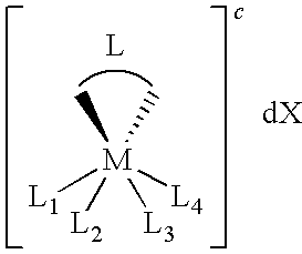


Priority Applications (1)
| Application Number | Priority Date | Filing Date | Title |
|---|---|---|---|
| US12/172,589 US8268143B2 (en) | 1999-11-15 | 2008-07-14 | Oxygen-effect free analyte sensor |
Applications Claiming Priority (6)
| Application Number | Priority Date | Filing Date | Title |
|---|---|---|---|
| US16556599P | 1999-11-15 | 1999-11-15 | |
| US09/712,452 US6605201B1 (en) | 1999-11-15 | 2000-11-14 | Transition metal complexes with bidentate ligand having an imidazole ring and sensor constructed therewith |
| US10/639,181 US7090756B2 (en) | 1999-11-15 | 2003-08-11 | Transition metal complexes with bidentate ligand having an imidazole ring |
| US11/503,519 US7918976B2 (en) | 1999-11-15 | 2006-08-10 | Transition metal complexes with bidentate ligand having an imidazole ring |
| US12/051,835 US8444834B2 (en) | 1999-11-15 | 2008-03-19 | Redox polymers for use in analyte monitoring |
| US12/172,589 US8268143B2 (en) | 1999-11-15 | 2008-07-14 | Oxygen-effect free analyte sensor |
Related Parent Applications (1)
| Application Number | Title | Priority Date | Filing Date |
|---|---|---|---|
| US12/051,835 Continuation-In-Part US8444834B2 (en) | 1999-11-15 | 2008-03-19 | Redox polymers for use in analyte monitoring |
Publications (2)
| Publication Number | Publication Date |
|---|---|
| US20090099434A1 true US20090099434A1 (en) | 2009-04-16 |
| US8268143B2 US8268143B2 (en) | 2012-09-18 |
Family
ID=40534887
Family Applications (1)
| Application Number | Title | Priority Date | Filing Date |
|---|---|---|---|
| US12/172,589 Expired - Lifetime US8268143B2 (en) | 1999-11-15 | 2008-07-14 | Oxygen-effect free analyte sensor |
Country Status (1)
| Country | Link |
|---|---|
| US (1) | US8268143B2 (en) |
Cited By (58)
| Publication number | Priority date | Publication date | Assignee | Title |
|---|---|---|---|---|
| US20070038044A1 (en) * | 2004-07-13 | 2007-02-15 | Dobbles J M | Analyte sensor |
| US20070197889A1 (en) * | 2006-02-22 | 2007-08-23 | Mark Brister | Analyte sensor |
| US20070244380A1 (en) * | 1998-04-30 | 2007-10-18 | Abbott Diabetes Care, Inc. | Analyte monitoring device and methods of use |
| EP1973464A1 (en) * | 2006-01-17 | 2008-10-01 | DexCom, Inc. | Low oxygen in vivo analyte sensor |
| US20090156919A1 (en) * | 2004-07-13 | 2009-06-18 | Dexcom, Inc. | Transcutaneous analyte sensor |
| US20100041971A1 (en) * | 2004-05-03 | 2010-02-18 | Dexcom, Inc. | Implantable analyte sensor |
| US7783333B2 (en) | 2004-07-13 | 2010-08-24 | Dexcom, Inc. | Transcutaneous medical device with variable stiffness |
| US7831287B2 (en) | 2006-10-04 | 2010-11-09 | Dexcom, Inc. | Dual electrode system for a continuous analyte sensor |
| US20100326843A1 (en) * | 2009-06-30 | 2010-12-30 | Abbott Diabetes Care Inc | Extruded analyte sensors and methods of using same |
| US7901354B2 (en) | 1997-03-04 | 2011-03-08 | Dexcom, Inc. | Low oxygen in vivo analyte sensor |
| US7905833B2 (en) | 2004-07-13 | 2011-03-15 | Dexcom, Inc. | Transcutaneous analyte sensor |
| US7920906B2 (en) | 2005-03-10 | 2011-04-05 | Dexcom, Inc. | System and methods for processing analyte sensor data for sensor calibration |
| US7927274B2 (en) | 2003-11-19 | 2011-04-19 | Dexcom, Inc. | Integrated receiver for continuous analyte sensor |
| US7976492B2 (en) | 2004-02-26 | 2011-07-12 | Dexcom, Inc. | Integrated delivery device for continuous glucose sensor |
| US8000763B2 (en) | 2009-06-30 | 2011-08-16 | Abbott Diabetes Care Inc. | Integrated devices having extruded electrode structures and methods of using same |
| WO2011130515A1 (en) * | 2010-04-14 | 2011-10-20 | The United States Of America, As Represented By The Secretary, Department Of Health And Human Services | Arylthiazolyl piperidines and related compounds as modulators of survival motor neuron (smn) protein production |
| US8160671B2 (en) | 2003-12-05 | 2012-04-17 | Dexcom, Inc. | Calibration techniques for a continuous analyte sensor |
| EP2448478A1 (en) * | 2009-06-30 | 2012-05-09 | Abbott Diabetes Care, Inc. | Extruded electrode structures and methods of using same |
| US20120181189A1 (en) * | 2009-09-24 | 2012-07-19 | Fresenius Medical Care Holdings, Inc. | Amperometric Creatinine Biosensor With Immobilized Enzyme-Polymer Composition And Systems Using Same, And Methods |
| US8287454B2 (en) | 1998-04-30 | 2012-10-16 | Abbott Diabetes Care Inc. | Analyte monitoring device and methods of use |
| US8287453B2 (en) | 2003-12-05 | 2012-10-16 | Dexcom, Inc. | Analyte sensor |
| US8346337B2 (en) | 1998-04-30 | 2013-01-01 | Abbott Diabetes Care Inc. | Analyte monitoring device and methods of use |
| US8394021B2 (en) | 2003-08-01 | 2013-03-12 | Dexcom, Inc. | System and methods for processing analyte sensor data |
| US8423114B2 (en) | 2006-10-04 | 2013-04-16 | Dexcom, Inc. | Dual electrode system for a continuous analyte sensor |
| US8465425B2 (en) | 1998-04-30 | 2013-06-18 | Abbott Diabetes Care Inc. | Analyte monitoring device and methods of use |
| US8562558B2 (en) | 2007-06-08 | 2013-10-22 | Dexcom, Inc. | Integrated medicament delivery device for use with continuous analyte sensor |
| US8612159B2 (en) | 1998-04-30 | 2013-12-17 | Abbott Diabetes Care Inc. | Analyte monitoring device and methods of use |
| US8637194B2 (en) | 2008-09-02 | 2014-01-28 | Bio-Nano Power, Llc | Bio-nano power cells and their uses |
| US20140027310A1 (en) * | 2012-07-27 | 2014-01-30 | Ohmx Corporation | Electric measurement of monolayers following pro-cleave detection of presence and activity of enzymes and other target analytes |
| US8652043B2 (en) | 2001-01-02 | 2014-02-18 | Abbott Diabetes Care Inc. | Analyte monitoring device and methods of use |
| US8663109B2 (en) | 2004-07-13 | 2014-03-04 | Dexcom, Inc. | Transcutaneous analyte sensor |
| US8676288B2 (en) | 1997-03-04 | 2014-03-18 | Dexcom, Inc. | Device and method for determining analyte levels |
| US8688188B2 (en) | 1998-04-30 | 2014-04-01 | Abbott Diabetes Care Inc. | Analyte monitoring device and methods of use |
| US8792955B2 (en) | 2004-05-03 | 2014-07-29 | Dexcom, Inc. | Transcutaneous analyte sensor |
| US8808228B2 (en) | 2004-02-26 | 2014-08-19 | Dexcom, Inc. | Integrated medicament delivery device for use with continuous analyte sensor |
| US8974386B2 (en) | 1998-04-30 | 2015-03-10 | Abbott Diabetes Care Inc. | Analyte monitoring device and methods of use |
| US9066695B2 (en) | 1998-04-30 | 2015-06-30 | Abbott Diabetes Care Inc. | Analyte monitoring device and methods of use |
| US9155496B2 (en) | 1997-03-04 | 2015-10-13 | Dexcom, Inc. | Low oxygen in vivo analyte sensor |
| US9247900B2 (en) | 2004-07-13 | 2016-02-02 | Dexcom, Inc. | Analyte sensor |
| US9328371B2 (en) | 2001-07-27 | 2016-05-03 | Dexcom, Inc. | Sensor head for use with implantable devices |
| US9404883B2 (en) | 2012-07-27 | 2016-08-02 | Ohmx Corporation | Electronic measurements of monolayers following homogeneous reactions of their components |
| US20160228678A1 (en) * | 2015-01-02 | 2016-08-11 | Pacific Diabetes Technologies | Highly Durable Dual Use Catheter for Analyte Sensing and Drug Delivery |
| US9439589B2 (en) | 1997-03-04 | 2016-09-13 | Dexcom, Inc. | Device and method for determining analyte levels |
| US9451908B2 (en) | 2006-10-04 | 2016-09-27 | Dexcom, Inc. | Analyte sensor |
| US9757061B2 (en) | 2006-01-17 | 2017-09-12 | Dexcom, Inc. | Low oxygen in vivo analyte sensor |
| US9986942B2 (en) | 2004-07-13 | 2018-06-05 | Dexcom, Inc. | Analyte sensor |
| US10653835B2 (en) | 2007-10-09 | 2020-05-19 | Dexcom, Inc. | Integrated insulin delivery system with continuous glucose sensor |
| US10980461B2 (en) | 2008-11-07 | 2021-04-20 | Dexcom, Inc. | Advanced analyte sensor calibration and error detection |
| US11000215B1 (en) | 2003-12-05 | 2021-05-11 | Dexcom, Inc. | Analyte sensor |
| CN114384135A (en) * | 2022-01-25 | 2022-04-22 | 四川大学 | Conductive nano-material glucose sensing material and preparation method and application thereof |
| US11331022B2 (en) | 2017-10-24 | 2022-05-17 | Dexcom, Inc. | Pre-connected analyte sensors |
| US11331020B2 (en) | 2020-02-06 | 2022-05-17 | Trustees Of Boston University | Enzyme-based electrochemical nicotine biosensor |
| US11350862B2 (en) | 2017-10-24 | 2022-06-07 | Dexcom, Inc. | Pre-connected analyte sensors |
| US11382539B2 (en) | 2006-10-04 | 2022-07-12 | Dexcom, Inc. | Analyte sensor |
| US11536685B2 (en) | 2020-02-06 | 2022-12-27 | Trustees Of Boston University | High throughput assay for identifying microbial redox enzymes |
| US11633133B2 (en) | 2003-12-05 | 2023-04-25 | Dexcom, Inc. | Dual electrode system for a continuous analyte sensor |
| US11633129B2 (en) | 2019-04-05 | 2023-04-25 | Cambridge Medical Technologies LLC | Non-invasive transdermal sampling and analysis device incorporating redox cofactors |
| US11801000B2 (en) | 2021-04-30 | 2023-10-31 | Trustees Of Boston University | Hormone electrochemical biosensor |
Families Citing this family (21)
| Publication number | Priority date | Publication date | Assignee | Title |
|---|---|---|---|---|
| US10598624B2 (en) | 2014-10-23 | 2020-03-24 | Abbott Diabetes Care Inc. | Electrodes having at least one sensing structure and methods for making and using the same |
| WO2016196516A1 (en) | 2015-06-03 | 2016-12-08 | William Kenneth Ward | Measurement of glucose in an insulin delivery catheter by minimizing the adverse effects of insulin preservatives |
| EP3967227A1 (en) | 2015-06-15 | 2022-03-16 | Abbott Diabetes Care Inc. | Stabilized lactate responsive enzymes, electrodes and sensors, and methods for making and using the same |
| US20190320947A1 (en) | 2018-04-19 | 2019-10-24 | Abbott Diabetes Care Inc. | Lactate sensors and associated methods |
| US20210236028A1 (en) | 2018-05-17 | 2021-08-05 | Abbott Diabetes Care Inc. | Analyte sensor antimicrobial configurations and adhesives |
| US20200237276A1 (en) | 2019-01-28 | 2020-07-30 | Abbott Diabetes Care Inc. | Analyte sensors employing multiple enzymes and methods associated therewith |
| CN113453620B (en) | 2019-01-28 | 2024-03-05 | 美国雅培糖尿病护理公司 | Analyte sensor and sensing method for dual detection of glucose and ethanol |
| MY196781A (en) | 2019-01-28 | 2023-05-03 | Abbott Diabetes Care Inc | Analyte sensors and sensing methods featuring dual detection of glucose and ketones |
| JP7135218B2 (en) | 2019-01-28 | 2022-09-12 | アボット ダイアベティス ケア インコーポレイテッド | Analyte sensor and detection method for detecting creatinine |
| AU2020358714A1 (en) | 2019-10-02 | 2022-05-12 | Abbott Diabetes Care Inc. | Detection of analytes by protein switches |
| WO2021133903A1 (en) | 2019-12-23 | 2021-07-01 | Abbott Diabetes Care Inc. | Analyte sensors and sensing methods featuring low-potential detection |
| CA3174337A1 (en) | 2020-05-29 | 2021-12-02 | Benjamin J. Feldman | Analyte sensors and sensing methods for detecting inhibitors of diaphorase |
| US20230248271A1 (en) | 2020-06-10 | 2023-08-10 | Abbott Diabetes Care Inc. | Analyte sensors featuring one or more detection-facilitating enhancements |
| WO2022125998A1 (en) | 2020-12-10 | 2022-06-16 | Abbott Diabetes Care Inc. | Analyte sensors for sensing ketones and methods of using the same |
| AU2021400588A1 (en) | 2020-12-15 | 2023-06-22 | Abbott Diabetes Care Inc. | Nad(p) depot for nad(p)-dependent enzyme-based sensors |
| WO2022140664A1 (en) | 2020-12-23 | 2022-06-30 | Abbott Diabetes Care Inc. | Analyte sensors for sensing glutamate and methods of using the same |
| JP2024501294A (en) | 2020-12-23 | 2024-01-11 | アボット ダイアベティス ケア インコーポレイテッド | Continuous potassium sensor and how to use it |
| EP4271825A1 (en) | 2020-12-30 | 2023-11-08 | Abbott Diabetes Care, Inc. | Analyte sensors for detecting asparagine and aspartate and methods of use thereof |
| WO2022147496A1 (en) | 2020-12-31 | 2022-07-07 | Abbott Diabetes Care Inc. | Analyte sensors with metal-containing redox mediators and methods of using the same |
| US20220202322A1 (en) | 2020-12-31 | 2022-06-30 | Abbott Diabetes Care Inc. | Drug release compositions and methods for delivery |
| US20240027390A1 (en) | 2022-07-19 | 2024-01-25 | Abbott Diabetes Care Inc. | Analyte sensors with reduced interferent signal and methods |
Citations (32)
| Publication number | Priority date | Publication date | Assignee | Title |
|---|---|---|---|---|
| US5262305A (en) * | 1991-03-04 | 1993-11-16 | E. Heller & Company | Interferant eliminating biosensors |
| US5262035A (en) * | 1989-08-02 | 1993-11-16 | E. Heller And Company | Enzyme electrodes |
| US5264105A (en) * | 1989-08-02 | 1993-11-23 | Gregg Brian A | Enzyme electrodes |
| US5264104A (en) * | 1989-08-02 | 1993-11-23 | Gregg Brian A | Enzyme electrodes |
| US5264092A (en) * | 1991-10-02 | 1993-11-23 | Moltech Corporation | Redox polymer modified electrode for the electrochemical regeneration of coenzyme |
| US5320725A (en) * | 1989-08-02 | 1994-06-14 | E. Heller & Company | Electrode and method for the detection of hydrogen peroxide |
| US5356786A (en) * | 1991-03-04 | 1994-10-18 | E. Heller & Company | Interferant eliminating biosensor |
| US5378628A (en) * | 1991-02-21 | 1995-01-03 | Asulab, S.A. | Sensor for measuring the amount of a component in solution |
| US5393903A (en) * | 1991-02-21 | 1995-02-28 | Asulab S.A. | Mono, bis or tris(substituted 2,2'-bipyridine) iron, ruthenium, osmium or vanadium complexes and their methods of preparation |
| US5410059A (en) * | 1992-12-15 | 1995-04-25 | Asulab S.A. | Transition metal complexes having 2,2'-bipyridine ligands substituted by at least one ammonium alkyl radical |
| US5437999A (en) * | 1994-02-22 | 1995-08-01 | Boehringer Mannheim Corporation | Electrochemical sensor |
| US5463057A (en) * | 1992-08-21 | 1995-10-31 | Ecole Polytechnique Federale De Lausanne, (Epfl) | Bi-pyridyl-rumetal complexes |
| US5589326A (en) * | 1993-12-30 | 1996-12-31 | Boehringer Mannheim Corporation | Osmium-containing redox mediator |
| US5593852A (en) * | 1993-12-02 | 1997-01-14 | Heller; Adam | Subcutaneous glucose electrode |
| US5665222A (en) * | 1995-10-11 | 1997-09-09 | E. Heller & Company | Soybean peroxidase electrochemical sensor |
| US5683832A (en) * | 1994-12-21 | 1997-11-04 | Asulab S.A. | Hydrophobic liquid salts, the preparation thereof and their appliction in electrochemistry |
| US5789592A (en) * | 1994-05-02 | 1998-08-04 | Ecole Polytechnique Federale De Lausanne | Phosphonated polypyridyl compounds and their complexes |
| US5804049A (en) * | 1993-09-15 | 1998-09-08 | Chiron Diagnostics Corporation | Material for establishing solid state contact for ion selective electrodes |
| US5972199A (en) * | 1995-10-11 | 1999-10-26 | E. Heller & Company | Electrochemical analyte sensors using thermostable peroxidase |
| US6103033A (en) * | 1998-03-04 | 2000-08-15 | Therasense, Inc. | Process for producing an electrochemical biosensor |
| US6120676A (en) * | 1997-02-06 | 2000-09-19 | Therasense, Inc. | Method of using a small volume in vitro analyte sensor |
| US6134461A (en) * | 1998-03-04 | 2000-10-17 | E. Heller & Company | Electrochemical analyte |
| US6175752B1 (en) * | 1998-04-30 | 2001-01-16 | Therasense, Inc. | Analyte monitoring device and methods of use |
| US6245988B1 (en) * | 1997-05-07 | 2001-06-12 | Ecole Polytechnique Federale De Lausanne | Metal complex photosensitizer and photovoltaic cell |
| US6262264B1 (en) * | 1998-06-01 | 2001-07-17 | Roche Diagnostics Corporation | Redox reversible imidazole osmium complex conjugates |
| US6278056B1 (en) * | 1998-07-15 | 2001-08-21 | Director-General Of Agency Of Industrial Science And Technology | Metal complex useful as sensitizer, dye-sensitized oxide semiconductor electrode and solar cell using same |
| US6299757B1 (en) * | 1998-10-08 | 2001-10-09 | Therasense, Inc. | Small volume in vitro analyte sensor with diffusible or non-leachable redox mediator |
| US6605200B1 (en) * | 1999-11-15 | 2003-08-12 | Therasense, Inc. | Polymeric transition metal complexes and uses thereof |
| US6616819B1 (en) * | 1999-11-04 | 2003-09-09 | Therasense, Inc. | Small volume in vitro analyte sensor and methods |
| US6746582B2 (en) * | 2000-05-12 | 2004-06-08 | Therasense, Inc. | Electrodes with multilayer membranes and methods of making the electrodes |
| US20050173245A1 (en) * | 2004-02-09 | 2005-08-11 | Benjamin Feldman | Membrane suitable for use in an analyte sensor, analyte sensor, and associated method |
| US20080035479A1 (en) * | 2004-07-28 | 2008-02-14 | Zuifang Liu | Redox polymers for use in electrochemical-based sensors |
Family Cites Families (7)
| Publication number | Priority date | Publication date | Assignee | Title |
|---|---|---|---|---|
| JP2971927B2 (en) | 1990-09-04 | 1999-11-08 | 汪芳 白井 | Tertipyridyl-bearing hydrophilic polymer and its coordinating polymer complex |
| GB9714905D0 (en) | 1997-07-16 | 1997-09-17 | Johnson Matthey Plc | Photosensitizers |
| WO1999059218A1 (en) | 1998-05-12 | 1999-11-18 | Ecole Polytechnique Federale De Lausanne (Epfl) Sri | Primary or secondary electrochemical generator |
| JP2002518998A (en) | 1998-06-24 | 2002-07-02 | セラセンス、インク. | Multi-sensor array and method for electrochemical recognition of nucleotide sequences |
| US6676816B2 (en) | 2001-05-11 | 2004-01-13 | Therasense, Inc. | Transition metal complexes with (pyridyl)imidazole ligands and sensors using said complexes |
| CN1322592C (en) | 2002-05-20 | 2007-06-20 | 日立麦克赛尔株式会社 | Photoelectric conversion device |
| JP4114012B2 (en) | 2005-03-31 | 2008-07-09 | Dic株式会社 | Multi-branched polyether polyol |
-
2008
- 2008-07-14 US US12/172,589 patent/US8268143B2/en not_active Expired - Lifetime
Patent Citations (44)
| Publication number | Priority date | Publication date | Assignee | Title |
|---|---|---|---|---|
| US5262035A (en) * | 1989-08-02 | 1993-11-16 | E. Heller And Company | Enzyme electrodes |
| US5264105A (en) * | 1989-08-02 | 1993-11-23 | Gregg Brian A | Enzyme electrodes |
| US5264104A (en) * | 1989-08-02 | 1993-11-23 | Gregg Brian A | Enzyme electrodes |
| US5320725A (en) * | 1989-08-02 | 1994-06-14 | E. Heller & Company | Electrode and method for the detection of hydrogen peroxide |
| US5378628A (en) * | 1991-02-21 | 1995-01-03 | Asulab, S.A. | Sensor for measuring the amount of a component in solution |
| US5393903A (en) * | 1991-02-21 | 1995-02-28 | Asulab S.A. | Mono, bis or tris(substituted 2,2'-bipyridine) iron, ruthenium, osmium or vanadium complexes and their methods of preparation |
| US5262305A (en) * | 1991-03-04 | 1993-11-16 | E. Heller & Company | Interferant eliminating biosensors |
| US5356786A (en) * | 1991-03-04 | 1994-10-18 | E. Heller & Company | Interferant eliminating biosensor |
| US5264092A (en) * | 1991-10-02 | 1993-11-23 | Moltech Corporation | Redox polymer modified electrode for the electrochemical regeneration of coenzyme |
| US5463057A (en) * | 1992-08-21 | 1995-10-31 | Ecole Polytechnique Federale De Lausanne, (Epfl) | Bi-pyridyl-rumetal complexes |
| US5410059A (en) * | 1992-12-15 | 1995-04-25 | Asulab S.A. | Transition metal complexes having 2,2'-bipyridine ligands substituted by at least one ammonium alkyl radical |
| US5804049A (en) * | 1993-09-15 | 1998-09-08 | Chiron Diagnostics Corporation | Material for establishing solid state contact for ion selective electrodes |
| US6121009A (en) * | 1993-12-02 | 2000-09-19 | E. Heller & Company | Electrochemical analyte measurement system |
| US5593852A (en) * | 1993-12-02 | 1997-01-14 | Heller; Adam | Subcutaneous glucose electrode |
| US6083710A (en) * | 1993-12-02 | 2000-07-04 | E. Heller & Company | Electrochemical analyte measurement system |
| US5965380A (en) * | 1993-12-02 | 1999-10-12 | E. Heller & Company | Subcutaneous glucose electrode |
| US5589326A (en) * | 1993-12-30 | 1996-12-31 | Boehringer Mannheim Corporation | Osmium-containing redox mediator |
| US5846702A (en) * | 1993-12-30 | 1998-12-08 | Boehringer Mannheim Corporation | Reagent including an osmium-containing redox mediator |
| US5437999A (en) * | 1994-02-22 | 1995-08-01 | Boehringer Mannheim Corporation | Electrochemical sensor |
| US5789592A (en) * | 1994-05-02 | 1998-08-04 | Ecole Polytechnique Federale De Lausanne | Phosphonated polypyridyl compounds and their complexes |
| US5683832A (en) * | 1994-12-21 | 1997-11-04 | Asulab S.A. | Hydrophobic liquid salts, the preparation thereof and their appliction in electrochemistry |
| US5972199A (en) * | 1995-10-11 | 1999-10-26 | E. Heller & Company | Electrochemical analyte sensors using thermostable peroxidase |
| US5665222A (en) * | 1995-10-11 | 1997-09-09 | E. Heller & Company | Soybean peroxidase electrochemical sensor |
| US6143164A (en) * | 1997-02-06 | 2000-11-07 | E. Heller & Company | Small volume in vitro analyte sensor |
| US6120676A (en) * | 1997-02-06 | 2000-09-19 | Therasense, Inc. | Method of using a small volume in vitro analyte sensor |
| US6245988B1 (en) * | 1997-05-07 | 2001-06-12 | Ecole Polytechnique Federale De Lausanne | Metal complex photosensitizer and photovoltaic cell |
| US6103033A (en) * | 1998-03-04 | 2000-08-15 | Therasense, Inc. | Process for producing an electrochemical biosensor |
| US6134461A (en) * | 1998-03-04 | 2000-10-17 | E. Heller & Company | Electrochemical analyte |
| US6175752B1 (en) * | 1998-04-30 | 2001-01-16 | Therasense, Inc. | Analyte monitoring device and methods of use |
| US20050199494A1 (en) * | 1998-04-30 | 2005-09-15 | James Say | Analyte monitoring device and methods of use |
| US6262264B1 (en) * | 1998-06-01 | 2001-07-17 | Roche Diagnostics Corporation | Redox reversible imidazole osmium complex conjugates |
| US6294062B1 (en) * | 1998-06-01 | 2001-09-25 | Roche Diagnostics Corporation | Method and device for electrochemical immunoassay of multiple analytes |
| US6352824B1 (en) * | 1998-06-01 | 2002-03-05 | Roche Diagnostics Corporation | Redox reversible bipyridyl-osmium complex conjugates |
| US6278056B1 (en) * | 1998-07-15 | 2001-08-21 | Director-General Of Agency Of Industrial Science And Technology | Metal complex useful as sensitizer, dye-sensitized oxide semiconductor electrode and solar cell using same |
| US6299757B1 (en) * | 1998-10-08 | 2001-10-09 | Therasense, Inc. | Small volume in vitro analyte sensor with diffusible or non-leachable redox mediator |
| US6338790B1 (en) * | 1998-10-08 | 2002-01-15 | Therasense, Inc. | Small volume in vitro analyte sensor with diffusible or non-leachable redox mediator |
| US6616819B1 (en) * | 1999-11-04 | 2003-09-09 | Therasense, Inc. | Small volume in vitro analyte sensor and methods |
| US6605200B1 (en) * | 1999-11-15 | 2003-08-12 | Therasense, Inc. | Polymeric transition metal complexes and uses thereof |
| US20040040840A1 (en) * | 1999-11-15 | 2004-03-04 | Therasense, Inc. | Transition metal complexes with bidentate ligand having an imidazole ring |
| US6605201B1 (en) * | 1999-11-15 | 2003-08-12 | Therasense, Inc. | Transition metal complexes with bidentate ligand having an imidazole ring and sensor constructed therewith |
| US6746582B2 (en) * | 2000-05-12 | 2004-06-08 | Therasense, Inc. | Electrodes with multilayer membranes and methods of making the electrodes |
| US20050173245A1 (en) * | 2004-02-09 | 2005-08-11 | Benjamin Feldman | Membrane suitable for use in an analyte sensor, analyte sensor, and associated method |
| US20080035479A1 (en) * | 2004-07-28 | 2008-02-14 | Zuifang Liu | Redox polymers for use in electrochemical-based sensors |
| US7429630B2 (en) * | 2004-07-28 | 2008-09-30 | Lifescan Scotland Limited | Redox polymers for use in electrochemical-based sensors |
Cited By (239)
| Publication number | Priority date | Publication date | Assignee | Title |
|---|---|---|---|---|
| US7901354B2 (en) | 1997-03-04 | 2011-03-08 | Dexcom, Inc. | Low oxygen in vivo analyte sensor |
| US9931067B2 (en) | 1997-03-04 | 2018-04-03 | Dexcom, Inc. | Device and method for determining analyte levels |
| US9439589B2 (en) | 1997-03-04 | 2016-09-13 | Dexcom, Inc. | Device and method for determining analyte levels |
| US9339223B2 (en) | 1997-03-04 | 2016-05-17 | Dexcom, Inc. | Device and method for determining analyte levels |
| US9155496B2 (en) | 1997-03-04 | 2015-10-13 | Dexcom, Inc. | Low oxygen in vivo analyte sensor |
| US8676288B2 (en) | 1997-03-04 | 2014-03-18 | Dexcom, Inc. | Device and method for determining analyte levels |
| US9042953B2 (en) | 1998-04-30 | 2015-05-26 | Abbott Diabetes Care Inc. | Analyte monitoring device and methods of use |
| US8353829B2 (en) | 1998-04-30 | 2013-01-15 | Abbott Diabetes Care Inc. | Analyte monitoring device and methods of use |
| US20090187088A1 (en) * | 1998-04-30 | 2009-07-23 | Abbott Diabetes Care Inc. | Analyte Monitoring Device and Methods of Use |
| US8880137B2 (en) | 1998-04-30 | 2014-11-04 | Abbott Diabetes Care Inc. | Analyte monitoring device and methods of use |
| US8774887B2 (en) | 1998-04-30 | 2014-07-08 | Abbott Diabetes Care Inc. | Analyte monitoring device and methods of use |
| US8744545B2 (en) | 1998-04-30 | 2014-06-03 | Abbott Diabetes Care Inc. | Analyte monitoring device and methods of use |
| US20100268047A1 (en) * | 1998-04-30 | 2010-10-21 | Abbott Diabetes Care Inc. | Analyte Monitoring Device and Methods of Use |
| US20100274111A1 (en) * | 1998-04-30 | 2010-10-28 | Abbott Diabetes Care Inc. | Analyte Monitoring Device and Methods of Use |
| US8734348B2 (en) | 1998-04-30 | 2014-05-27 | Abbott Diabetes Care Inc. | Analyte monitoring device and methods of use |
| US8734346B2 (en) | 1998-04-30 | 2014-05-27 | Abbott Diabetes Care Inc. | Analyte monitoring device and methods of use |
| US8738109B2 (en) | 1998-04-30 | 2014-05-27 | Abbott Diabetes Care Inc. | Analyte monitoring device and methods of use |
| US8688188B2 (en) | 1998-04-30 | 2014-04-01 | Abbott Diabetes Care Inc. | Analyte monitoring device and methods of use |
| US8672844B2 (en) | 1998-04-30 | 2014-03-18 | Abbott Diabetes Care Inc. | Analyte monitoring device and methods of use |
| US10478108B2 (en) | 1998-04-30 | 2019-11-19 | Abbott Diabetes Care Inc. | Analyte monitoring device and methods of use |
| US9066695B2 (en) | 1998-04-30 | 2015-06-30 | Abbott Diabetes Care Inc. | Analyte monitoring device and methods of use |
| US9011331B2 (en) | 1998-04-30 | 2015-04-21 | Abbott Diabetes Care Inc. | Analyte monitoring device and methods of use |
| US8670815B2 (en) | 1998-04-30 | 2014-03-11 | Abbott Diabetes Care Inc. | Analyte monitoring device and methods of use |
| US9014773B2 (en) | 1998-04-30 | 2015-04-21 | Abbott Diabetes Care Inc. | Analyte monitoring device and methods of use |
| US8666469B2 (en) | 1998-04-30 | 2014-03-04 | Abbott Diabetes Care Inc. | Analyte monitoring device and methods of use |
| US8660627B2 (en) | 1998-04-30 | 2014-02-25 | Abbott Diabetes Care Inc. | Analyte monitoring device and methods of use |
| US8649841B2 (en) | 1998-04-30 | 2014-02-11 | Abbott Diabetes Care Inc. | Analyte monitoring device and methods of use |
| US8641619B2 (en) | 1998-04-30 | 2014-02-04 | Abbott Diabetes Care Inc. | Analyte monitoring device and methods of use |
| US8622906B2 (en) | 1998-04-30 | 2014-01-07 | Abbott Diabetes Care Inc. | Analyte monitoring device and methods of use |
| US8162829B2 (en) | 1998-04-30 | 2012-04-24 | Abbott Diabetes Care Inc. | Analyte monitoring device and methods of use |
| US8175673B2 (en) | 1998-04-30 | 2012-05-08 | Abbott Diabetes Care Inc. | Analyte monitoring device and methods of use |
| US8617071B2 (en) | 1998-04-30 | 2013-12-31 | Abbott Diabetes Care Inc. | Analyte monitoring device and methods of use |
| US8177716B2 (en) | 1998-04-30 | 2012-05-15 | Abbott Diabetes Care Inc. | Analyte monitoring device and methods of use |
| US8224413B2 (en) | 1998-04-30 | 2012-07-17 | Abbott Diabetes Care Inc. | Analyte monitoring device and methods of use |
| US8275439B2 (en) | 1998-04-30 | 2012-09-25 | Abbott Diabetes Care Inc. | Analyte monitoring device and methods of use |
| US8226557B2 (en) | 1998-04-30 | 2012-07-24 | Abbott Diabetes Care Inc. | Analyte monitoring device and methods of use |
| US8226555B2 (en) | 1998-04-30 | 2012-07-24 | Abbott Diabetes Care Inc. | Analyte monitoring device and methods of use |
| US8226558B2 (en) | 1998-04-30 | 2012-07-24 | Abbott Diabetes Care Inc. | Analyte monitoring device and methods of use |
| US8612159B2 (en) | 1998-04-30 | 2013-12-17 | Abbott Diabetes Care Inc. | Analyte monitoring device and methods of use |
| US8231532B2 (en) | 1998-04-30 | 2012-07-31 | Abbott Diabetes Care Inc. | Analyte monitoring device and methods of use |
| US8235896B2 (en) | 1998-04-30 | 2012-08-07 | Abbott Diabetes Care Inc. | Analyte monitoring device and methods of use |
| US8597189B2 (en) | 1998-04-30 | 2013-12-03 | Abbott Diabetes Care Inc. | Analyte monitoring device and methods of use |
| US8255031B2 (en) | 1998-04-30 | 2012-08-28 | Abbott Diabetes Care Inc. | Analyte monitoring device and methods of use |
| US8260392B2 (en) | 1998-04-30 | 2012-09-04 | Abbott Diabetes Care Inc. | Analyte monitoring device and methods of use |
| US8265726B2 (en) | 1998-04-30 | 2012-09-11 | Abbott Diabetes Care Inc. | Analyte monitoring device and methods of use |
| US20070244380A1 (en) * | 1998-04-30 | 2007-10-18 | Abbott Diabetes Care, Inc. | Analyte monitoring device and methods of use |
| US8273022B2 (en) | 1998-04-30 | 2012-09-25 | Abbott Diabetes Care Inc. | Analyte monitoring device and methods of use |
| US20070249919A1 (en) * | 1998-04-30 | 2007-10-25 | Abbott Diabetes Care, Inc. | Analyte monitoring device and methods of use |
| US8287454B2 (en) | 1998-04-30 | 2012-10-16 | Abbott Diabetes Care Inc. | Analyte monitoring device and methods of use |
| US8974386B2 (en) | 1998-04-30 | 2015-03-10 | Abbott Diabetes Care Inc. | Analyte monitoring device and methods of use |
| US8480580B2 (en) | 1998-04-30 | 2013-07-09 | Abbott Diabetes Care Inc. | Analyte monitoring device and methods of use |
| US8306598B2 (en) | 1998-04-30 | 2012-11-06 | Abbott Diabetes Care Inc. | Analyte monitoring device and methods of use |
| US9326714B2 (en) | 1998-04-30 | 2016-05-03 | Abbott Diabetes Care Inc. | Analyte monitoring device and methods of use |
| US8346336B2 (en) | 1998-04-30 | 2013-01-01 | Abbott Diabetes Care Inc. | Analyte monitoring device and methods of use |
| US8346337B2 (en) | 1998-04-30 | 2013-01-01 | Abbott Diabetes Care Inc. | Analyte monitoring device and methods of use |
| US8840553B2 (en) | 1998-04-30 | 2014-09-23 | Abbott Diabetes Care Inc. | Analyte monitoring device and methods of use |
| US8357091B2 (en) | 1998-04-30 | 2013-01-22 | Abbott Diabetes Care Inc. | Analyte monitoring device and methods of use |
| US8366614B2 (en) | 1998-04-30 | 2013-02-05 | Abbott Diabetes Care Inc. | Analyte monitoring device and methods of use |
| US8372005B2 (en) | 1998-04-30 | 2013-02-12 | Abbott Diabetes Care Inc. | Analyte monitoring device and methods of use |
| US8380273B2 (en) | 1998-04-30 | 2013-02-19 | Abbott Diabetes Care Inc. | Analyte monitoring device and methods of use |
| US8391945B2 (en) | 1998-04-30 | 2013-03-05 | Abbott Diabetes Care Inc. | Analyte monitoring device and methods of use |
| US9066697B2 (en) | 1998-04-30 | 2015-06-30 | Abbott Diabetes Care Inc. | Analyte monitoring device and methods of use |
| US8409131B2 (en) | 1998-04-30 | 2013-04-02 | Abbott Diabetes Care Inc. | Analyte monitoring device and methods of use |
| US8473021B2 (en) | 1998-04-30 | 2013-06-25 | Abbott Diabetes Care Inc. | Analyte monitoring device and methods of use |
| US8465425B2 (en) | 1998-04-30 | 2013-06-18 | Abbott Diabetes Care Inc. | Analyte monitoring device and methods of use |
| US9066694B2 (en) | 1998-04-30 | 2015-06-30 | Abbott Diabetes Care Inc. | Analyte monitoring device and methods of use |
| US9072477B2 (en) | 1998-04-30 | 2015-07-07 | Abbott Diabetes Care Inc. | Analyte monitoring device and methods of use |
| US9610034B2 (en) | 2001-01-02 | 2017-04-04 | Abbott Diabetes Care Inc. | Analyte monitoring device and methods of use |
| US8668645B2 (en) | 2001-01-02 | 2014-03-11 | Abbott Diabetes Care Inc. | Analyte monitoring device and methods of use |
| US8652043B2 (en) | 2001-01-02 | 2014-02-18 | Abbott Diabetes Care Inc. | Analyte monitoring device and methods of use |
| US9011332B2 (en) | 2001-01-02 | 2015-04-21 | Abbott Diabetes Care Inc. | Analyte monitoring device and methods of use |
| US9498159B2 (en) | 2001-01-02 | 2016-11-22 | Abbott Diabetes Care Inc. | Analyte monitoring device and methods of use |
| US9328371B2 (en) | 2001-07-27 | 2016-05-03 | Dexcom, Inc. | Sensor head for use with implantable devices |
| US9804114B2 (en) | 2001-07-27 | 2017-10-31 | Dexcom, Inc. | Sensor head for use with implantable devices |
| US8394021B2 (en) | 2003-08-01 | 2013-03-12 | Dexcom, Inc. | System and methods for processing analyte sensor data |
| US8282550B2 (en) | 2003-11-19 | 2012-10-09 | Dexcom, Inc. | Integrated receiver for continuous analyte sensor |
| US7927274B2 (en) | 2003-11-19 | 2011-04-19 | Dexcom, Inc. | Integrated receiver for continuous analyte sensor |
| US11564602B2 (en) | 2003-11-19 | 2023-01-31 | Dexcom, Inc. | Integrated receiver for continuous analyte sensor |
| US9579053B2 (en) | 2003-12-05 | 2017-02-28 | Dexcom, Inc. | Dual electrode system for a continuous analyte sensor |
| US8160671B2 (en) | 2003-12-05 | 2012-04-17 | Dexcom, Inc. | Calibration techniques for a continuous analyte sensor |
| US11633133B2 (en) | 2003-12-05 | 2023-04-25 | Dexcom, Inc. | Dual electrode system for a continuous analyte sensor |
| US8249684B2 (en) | 2003-12-05 | 2012-08-21 | Dexcom, Inc. | Calibration techniques for a continuous analyte sensor |
| US8287453B2 (en) | 2003-12-05 | 2012-10-16 | Dexcom, Inc. | Analyte sensor |
| US11020031B1 (en) | 2003-12-05 | 2021-06-01 | Dexcom, Inc. | Analyte sensor |
| US11000215B1 (en) | 2003-12-05 | 2021-05-11 | Dexcom, Inc. | Analyte sensor |
| US8428678B2 (en) | 2003-12-05 | 2013-04-23 | Dexcom, Inc. | Calibration techniques for a continuous analyte sensor |
| US10299712B2 (en) | 2003-12-05 | 2019-05-28 | Dexcom, Inc. | Dual electrode system for a continuous analyte sensor |
| US8911369B2 (en) | 2003-12-05 | 2014-12-16 | Dexcom, Inc. | Dual electrode system for a continuous analyte sensor |
| US10278580B2 (en) | 2004-02-26 | 2019-05-07 | Dexcom, Inc. | Integrated medicament delivery device for use with continuous analyte sensor |
| US11246990B2 (en) | 2004-02-26 | 2022-02-15 | Dexcom, Inc. | Integrated delivery device for continuous glucose sensor |
| US10835672B2 (en) | 2004-02-26 | 2020-11-17 | Dexcom, Inc. | Integrated insulin delivery system with continuous glucose sensor |
| US10966609B2 (en) | 2004-02-26 | 2021-04-06 | Dexcom, Inc. | Integrated medicament delivery device for use with continuous analyte sensor |
| US8926585B2 (en) | 2004-02-26 | 2015-01-06 | Dexcom, Inc. | Integrated delivery device for continuous glucose sensor |
| US8721585B2 (en) | 2004-02-26 | 2014-05-13 | Dex Com, Inc. | Integrated delivery device for continuous glucose sensor |
| US8920401B2 (en) | 2004-02-26 | 2014-12-30 | Dexcom, Inc. | Integrated delivery device for continuous glucose sensor |
| US7976492B2 (en) | 2004-02-26 | 2011-07-12 | Dexcom, Inc. | Integrated delivery device for continuous glucose sensor |
| US9937293B2 (en) | 2004-02-26 | 2018-04-10 | Dexcom, Inc. | Integrated delivery device for continuous glucose sensor |
| US8808228B2 (en) | 2004-02-26 | 2014-08-19 | Dexcom, Inc. | Integrated medicament delivery device for use with continuous analyte sensor |
| US8882741B2 (en) | 2004-02-26 | 2014-11-11 | Dexcom, Inc. | Integrated delivery device for continuous glucose sensor |
| US9050413B2 (en) | 2004-02-26 | 2015-06-09 | Dexcom, Inc. | Integrated delivery device for continuous glucose sensor |
| US9155843B2 (en) | 2004-02-26 | 2015-10-13 | Dexcom, Inc. | Integrated delivery device for continuous glucose sensor |
| US9833143B2 (en) | 2004-05-03 | 2017-12-05 | Dexcom, Inc. | Transcutaneous analyte sensor |
| US8792955B2 (en) | 2004-05-03 | 2014-07-29 | Dexcom, Inc. | Transcutaneous analyte sensor |
| US20100041971A1 (en) * | 2004-05-03 | 2010-02-18 | Dexcom, Inc. | Implantable analyte sensor |
| US10327638B2 (en) | 2004-05-03 | 2019-06-25 | Dexcom, Inc. | Transcutaneous analyte sensor |
| US8457708B2 (en) | 2004-07-13 | 2013-06-04 | Dexcom, Inc. | Transcutaneous analyte sensor |
| US10993642B2 (en) | 2004-07-13 | 2021-05-04 | Dexcom, Inc. | Analyte sensor |
| US8801611B2 (en) | 2004-07-13 | 2014-08-12 | Dexcom, Inc. | Transcutaneous analyte sensor |
| US8886272B2 (en) | 2004-07-13 | 2014-11-11 | Dexcom, Inc. | Analyte sensor |
| US8792954B2 (en) | 2004-07-13 | 2014-07-29 | Dexcom, Inc. | Transcutaneous analyte sensor |
| US8792953B2 (en) | 2004-07-13 | 2014-07-29 | Dexcom, Inc. | Transcutaneous analyte sensor |
| US11883164B2 (en) | 2004-07-13 | 2024-01-30 | Dexcom, Inc. | System and methods for processing analyte sensor data for sensor calibration |
| US8721545B2 (en) | 2004-07-13 | 2014-05-13 | Dexcom, Inc. | Transcutaneous analyte sensor |
| US7783333B2 (en) | 2004-07-13 | 2010-08-24 | Dexcom, Inc. | Transcutaneous medical device with variable stiffness |
| US8690775B2 (en) | 2004-07-13 | 2014-04-08 | Dexcom, Inc. | Transcutaneous analyte sensor |
| US11064917B2 (en) | 2004-07-13 | 2021-07-20 | Dexcom, Inc. | Analyte sensor |
| US11045120B2 (en) | 2004-07-13 | 2021-06-29 | Dexcom, Inc. | Analyte sensor |
| US8663109B2 (en) | 2004-07-13 | 2014-03-04 | Dexcom, Inc. | Transcutaneous analyte sensor |
| US11026605B1 (en) | 2004-07-13 | 2021-06-08 | Dexcom, Inc. | Analyte sensor |
| US20070038044A1 (en) * | 2004-07-13 | 2007-02-15 | Dobbles J M | Analyte sensor |
| US9044199B2 (en) | 2004-07-13 | 2015-06-02 | Dexcom, Inc. | Transcutaneous analyte sensor |
| US7857760B2 (en) | 2004-07-13 | 2010-12-28 | Dexcom, Inc. | Analyte sensor |
| US8615282B2 (en) | 2004-07-13 | 2013-12-24 | Dexcom, Inc. | Analyte sensor |
| US8812072B2 (en) | 2004-07-13 | 2014-08-19 | Dexcom, Inc. | Transcutaneous medical device with variable stiffness |
| US8515519B2 (en) | 2004-07-13 | 2013-08-20 | Dexcom, Inc. | Transcutaneous analyte sensor |
| US8483791B2 (en) | 2004-07-13 | 2013-07-09 | Dexcom, Inc. | Transcutaneous analyte sensor |
| US20090163790A1 (en) * | 2004-07-13 | 2009-06-25 | Dexcom, Inc. | Transcutaneous analyte sensor |
| US10993641B2 (en) | 2004-07-13 | 2021-05-04 | Dexcom, Inc. | Analyte sensor |
| US9078626B2 (en) | 2004-07-13 | 2015-07-14 | Dexcom, Inc. | Transcutaneous analyte sensor |
| US10980452B2 (en) | 2004-07-13 | 2021-04-20 | Dexcom, Inc. | Analyte sensor |
| US7885697B2 (en) | 2004-07-13 | 2011-02-08 | Dexcom, Inc. | Transcutaneous analyte sensor |
| US9247900B2 (en) | 2004-07-13 | 2016-02-02 | Dexcom, Inc. | Analyte sensor |
| US8313434B2 (en) | 2004-07-13 | 2012-11-20 | Dexcom, Inc. | Analyte sensor inserter system |
| US10932700B2 (en) | 2004-07-13 | 2021-03-02 | Dexcom, Inc. | Analyte sensor |
| US10918314B2 (en) | 2004-07-13 | 2021-02-16 | Dexcom, Inc. | Analyte sensor |
| US9060742B2 (en) | 2004-07-13 | 2015-06-23 | Dexcom, Inc. | Transcutaneous analyte sensor |
| US10918315B2 (en) | 2004-07-13 | 2021-02-16 | Dexcom, Inc. | Analyte sensor |
| US10918313B2 (en) | 2004-07-13 | 2021-02-16 | Dexcom, Inc. | Analyte sensor |
| US9414777B2 (en) | 2004-07-13 | 2016-08-16 | Dexcom, Inc. | Transcutaneous analyte sensor |
| US20090156919A1 (en) * | 2004-07-13 | 2009-06-18 | Dexcom, Inc. | Transcutaneous analyte sensor |
| US10827956B2 (en) | 2004-07-13 | 2020-11-10 | Dexcom, Inc. | Analyte sensor |
| US10813576B2 (en) | 2004-07-13 | 2020-10-27 | Dexcom, Inc. | Analyte sensor |
| US8231531B2 (en) | 2004-07-13 | 2012-07-31 | Dexcom, Inc. | Analyte sensor |
| US10799158B2 (en) | 2004-07-13 | 2020-10-13 | Dexcom, Inc. | Analyte sensor |
| US10799159B2 (en) | 2004-07-13 | 2020-10-13 | Dexcom, Inc. | Analyte sensor |
| US10722152B2 (en) | 2004-07-13 | 2020-07-28 | Dexcom, Inc. | Analyte sensor |
| US9610031B2 (en) | 2004-07-13 | 2017-04-04 | Dexcom, Inc. | Transcutaneous analyte sensor |
| US9668677B2 (en) | 2004-07-13 | 2017-06-06 | Dexcom, Inc. | Analyte sensor |
| US10709363B2 (en) | 2004-07-13 | 2020-07-14 | Dexcom, Inc. | Analyte sensor |
| US10709362B2 (en) | 2004-07-13 | 2020-07-14 | Dexcom, Inc. | Analyte sensor |
| US10524703B2 (en) | 2004-07-13 | 2020-01-07 | Dexcom, Inc. | Transcutaneous analyte sensor |
| US9775543B2 (en) | 2004-07-13 | 2017-10-03 | Dexcom, Inc. | Transcutaneous analyte sensor |
| US7905833B2 (en) | 2004-07-13 | 2011-03-15 | Dexcom, Inc. | Transcutaneous analyte sensor |
| US9801572B2 (en) | 2004-07-13 | 2017-10-31 | Dexcom, Inc. | Transcutaneous analyte sensor |
| US9814414B2 (en) | 2004-07-13 | 2017-11-14 | Dexcom, Inc. | Transcutaneous analyte sensor |
| US10314525B2 (en) | 2004-07-13 | 2019-06-11 | Dexcom, Inc. | Analyte sensor |
| US20070173708A9 (en) * | 2004-07-13 | 2007-07-26 | Dobbles J M | Analyte sensor |
| US7949381B2 (en) | 2004-07-13 | 2011-05-24 | Dexcom, Inc. | Transcutaneous analyte sensor |
| US9986942B2 (en) | 2004-07-13 | 2018-06-05 | Dexcom, Inc. | Analyte sensor |
| US10022078B2 (en) | 2004-07-13 | 2018-07-17 | Dexcom, Inc. | Analyte sensor |
| US7946984B2 (en) | 2004-07-13 | 2011-05-24 | Dexcom, Inc. | Transcutaneous analyte sensor |
| US10898114B2 (en) | 2005-03-10 | 2021-01-26 | Dexcom, Inc. | System and methods for processing analyte sensor data for sensor calibration |
| US10918318B2 (en) | 2005-03-10 | 2021-02-16 | Dexcom, Inc. | System and methods for processing analyte sensor data for sensor calibration |
| US10709364B2 (en) | 2005-03-10 | 2020-07-14 | Dexcom, Inc. | System and methods for processing analyte sensor data for sensor calibration |
| US10925524B2 (en) | 2005-03-10 | 2021-02-23 | Dexcom, Inc. | System and methods for processing analyte sensor data for sensor calibration |
| US10856787B2 (en) | 2005-03-10 | 2020-12-08 | Dexcom, Inc. | System and methods for processing analyte sensor data for sensor calibration |
| US10918317B2 (en) | 2005-03-10 | 2021-02-16 | Dexcom, Inc. | System and methods for processing analyte sensor data for sensor calibration |
| US10918316B2 (en) | 2005-03-10 | 2021-02-16 | Dexcom, Inc. | System and methods for processing analyte sensor data for sensor calibration |
| US10716498B2 (en) | 2005-03-10 | 2020-07-21 | Dexcom, Inc. | System and methods for processing analyte sensor data for sensor calibration |
| US11000213B2 (en) | 2005-03-10 | 2021-05-11 | Dexcom, Inc. | System and methods for processing analyte sensor data for sensor calibration |
| US11051726B2 (en) | 2005-03-10 | 2021-07-06 | Dexcom, Inc. | System and methods for processing analyte sensor data for sensor calibration |
| US7920906B2 (en) | 2005-03-10 | 2011-04-05 | Dexcom, Inc. | System and methods for processing analyte sensor data for sensor calibration |
| US10743801B2 (en) | 2005-03-10 | 2020-08-18 | Dexcom, Inc. | System and methods for processing analyte sensor data for sensor calibration |
| US10610136B2 (en) | 2005-03-10 | 2020-04-07 | Dexcom, Inc. | System and methods for processing analyte sensor data for sensor calibration |
| US10610135B2 (en) | 2005-03-10 | 2020-04-07 | Dexcom, Inc. | System and methods for processing analyte sensor data for sensor calibration |
| US10610137B2 (en) | 2005-03-10 | 2020-04-07 | Dexcom, Inc. | System and methods for processing analyte sensor data for sensor calibration |
| US10617336B2 (en) | 2005-03-10 | 2020-04-14 | Dexcom, Inc. | System and methods for processing analyte sensor data for sensor calibration |
| US10813577B2 (en) | 2005-06-21 | 2020-10-27 | Dexcom, Inc. | Analyte sensor |
| US10952652B2 (en) | 2005-11-01 | 2021-03-23 | Abbott Diabetes Care Inc. | Analyte monitoring device and methods of use |
| US10231654B2 (en) | 2005-11-01 | 2019-03-19 | Abbott Diabetes Care Inc. | Analyte monitoring device and methods of use |
| US11103165B2 (en) | 2005-11-01 | 2021-08-31 | Abbott Diabetes Care Inc. | Analyte monitoring device and methods of use |
| US10201301B2 (en) | 2005-11-01 | 2019-02-12 | Abbott Diabetes Care Inc. | Analyte monitoring device and methods of use |
| US11911151B1 (en) | 2005-11-01 | 2024-02-27 | Abbott Diabetes Care Inc. | Analyte monitoring device and methods of use |
| US11363975B2 (en) | 2005-11-01 | 2022-06-21 | Abbott Diabetes Care Inc. | Analyte monitoring device and methods of use |
| US8915850B2 (en) | 2005-11-01 | 2014-12-23 | Abbott Diabetes Care Inc. | Analyte monitoring device and methods of use |
| US11272867B2 (en) | 2005-11-01 | 2022-03-15 | Abbott Diabetes Care Inc. | Analyte monitoring device and methods of use |
| US9078607B2 (en) | 2005-11-01 | 2015-07-14 | Abbott Diabetes Care Inc. | Analyte monitoring device and methods of use |
| US11399748B2 (en) | 2005-11-01 | 2022-08-02 | Abbott Diabetes Care Inc. | Analyte monitoring device and methods of use |
| US9326716B2 (en) | 2005-11-01 | 2016-05-03 | Abbott Diabetes Care Inc. | Analyte monitoring device and methods of use |
| US8920319B2 (en) | 2005-11-01 | 2014-12-30 | Abbott Diabetes Care Inc. | Analyte monitoring device and methods of use |
| EP1973464A1 (en) * | 2006-01-17 | 2008-10-01 | DexCom, Inc. | Low oxygen in vivo analyte sensor |
| EP1973464A4 (en) * | 2006-01-17 | 2010-04-07 | Dexcom Inc | Low oxygen in vivo analyte sensor |
| US9757061B2 (en) | 2006-01-17 | 2017-09-12 | Dexcom, Inc. | Low oxygen in vivo analyte sensor |
| EP3366201A1 (en) * | 2006-01-17 | 2018-08-29 | DexCom, Inc. | Low oxygen in vivo analyte sensor |
| US11596332B2 (en) | 2006-01-17 | 2023-03-07 | Dexcom, Inc. | Low oxygen in vivo analyte sensor |
| US11191458B2 (en) | 2006-01-17 | 2021-12-07 | Dexcom, Inc. | Low oxygen in vivo analyte sensor |
| US10265000B2 (en) | 2006-01-17 | 2019-04-23 | Dexcom, Inc. | Low oxygen in vivo analyte sensor |
| US9724028B2 (en) | 2006-02-22 | 2017-08-08 | Dexcom, Inc. | Analyte sensor |
| US20070197889A1 (en) * | 2006-02-22 | 2007-08-23 | Mark Brister | Analyte sensor |
| US8133178B2 (en) | 2006-02-22 | 2012-03-13 | Dexcom, Inc. | Analyte sensor |
| US10136844B2 (en) | 2006-10-04 | 2018-11-27 | Dexcom, Inc. | Dual electrode system for a continuous analyte sensor |
| US8423114B2 (en) | 2006-10-04 | 2013-04-16 | Dexcom, Inc. | Dual electrode system for a continuous analyte sensor |
| US9451908B2 (en) | 2006-10-04 | 2016-09-27 | Dexcom, Inc. | Analyte sensor |
| US7831287B2 (en) | 2006-10-04 | 2010-11-09 | Dexcom, Inc. | Dual electrode system for a continuous analyte sensor |
| US11399745B2 (en) | 2006-10-04 | 2022-08-02 | Dexcom, Inc. | Dual electrode system for a continuous analyte sensor |
| US9504413B2 (en) | 2006-10-04 | 2016-11-29 | Dexcom, Inc. | Dual electrode system for a continuous analyte sensor |
| US11382539B2 (en) | 2006-10-04 | 2022-07-12 | Dexcom, Inc. | Analyte sensor |
| US10349873B2 (en) | 2006-10-04 | 2019-07-16 | Dexcom, Inc. | Analyte sensor |
| US8562558B2 (en) | 2007-06-08 | 2013-10-22 | Dexcom, Inc. | Integrated medicament delivery device for use with continuous analyte sensor |
| US10403012B2 (en) | 2007-06-08 | 2019-09-03 | Dexcom, Inc. | Integrated medicament delivery device for use with continuous analyte sensor |
| US11373347B2 (en) | 2007-06-08 | 2022-06-28 | Dexcom, Inc. | Integrated medicament delivery device for use with continuous analyte sensor |
| US9741139B2 (en) | 2007-06-08 | 2017-08-22 | Dexcom, Inc. | Integrated medicament delivery device for use with continuous analyte sensor |
| US11744943B2 (en) | 2007-10-09 | 2023-09-05 | Dexcom, Inc. | Integrated insulin delivery system with continuous glucose sensor |
| US10653835B2 (en) | 2007-10-09 | 2020-05-19 | Dexcom, Inc. | Integrated insulin delivery system with continuous glucose sensor |
| US11160926B1 (en) | 2007-10-09 | 2021-11-02 | Dexcom, Inc. | Pre-connected analyte sensors |
| US8637194B2 (en) | 2008-09-02 | 2014-01-28 | Bio-Nano Power, Llc | Bio-nano power cells and their uses |
| US10980461B2 (en) | 2008-11-07 | 2021-04-20 | Dexcom, Inc. | Advanced analyte sensor calibration and error detection |
| US8000763B2 (en) | 2009-06-30 | 2011-08-16 | Abbott Diabetes Care Inc. | Integrated devices having extruded electrode structures and methods of using same |
| EP2448478A1 (en) * | 2009-06-30 | 2012-05-09 | Abbott Diabetes Care, Inc. | Extruded electrode structures and methods of using same |
| EP2448478A4 (en) * | 2009-06-30 | 2014-03-12 | Abbott Diabetes Care Inc | Extruded electrode structures and methods of using same |
| US20100326843A1 (en) * | 2009-06-30 | 2010-12-30 | Abbott Diabetes Care Inc | Extruded analyte sensors and methods of using same |
| US8437827B2 (en) | 2009-06-30 | 2013-05-07 | Abbott Diabetes Care Inc. | Extruded analyte sensors and methods of using same |
| US8298158B2 (en) | 2009-06-30 | 2012-10-30 | Abbott Diabetes Care Inc. | Integrated devices having extruded electrode structures and methods of using same |
| US20120181189A1 (en) * | 2009-09-24 | 2012-07-19 | Fresenius Medical Care Holdings, Inc. | Amperometric Creatinine Biosensor With Immobilized Enzyme-Polymer Composition And Systems Using Same, And Methods |
| WO2011130515A1 (en) * | 2010-04-14 | 2011-10-20 | The United States Of America, As Represented By The Secretary, Department Of Health And Human Services | Arylthiazolyl piperidines and related compounds as modulators of survival motor neuron (smn) protein production |
| US9404883B2 (en) | 2012-07-27 | 2016-08-02 | Ohmx Corporation | Electronic measurements of monolayers following homogeneous reactions of their components |
| US9416390B2 (en) * | 2012-07-27 | 2016-08-16 | Ohmx Corporation | Electric measurement of monolayers following pro-cleave detection of presence and activity of enzymes and other target analytes |
| US20140027310A1 (en) * | 2012-07-27 | 2014-01-30 | Ohmx Corporation | Electric measurement of monolayers following pro-cleave detection of presence and activity of enzymes and other target analytes |
| US20160228678A1 (en) * | 2015-01-02 | 2016-08-11 | Pacific Diabetes Technologies | Highly Durable Dual Use Catheter for Analyte Sensing and Drug Delivery |
| US11706876B2 (en) | 2017-10-24 | 2023-07-18 | Dexcom, Inc. | Pre-connected analyte sensors |
| US11382540B2 (en) | 2017-10-24 | 2022-07-12 | Dexcom, Inc. | Pre-connected analyte sensors |
| US11350862B2 (en) | 2017-10-24 | 2022-06-07 | Dexcom, Inc. | Pre-connected analyte sensors |
| US11331022B2 (en) | 2017-10-24 | 2022-05-17 | Dexcom, Inc. | Pre-connected analyte sensors |
| US11943876B2 (en) | 2017-10-24 | 2024-03-26 | Dexcom, Inc. | Pre-connected analyte sensors |
| US11633129B2 (en) | 2019-04-05 | 2023-04-25 | Cambridge Medical Technologies LLC | Non-invasive transdermal sampling and analysis device incorporating redox cofactors |
| US11536685B2 (en) | 2020-02-06 | 2022-12-27 | Trustees Of Boston University | High throughput assay for identifying microbial redox enzymes |
| US11331020B2 (en) | 2020-02-06 | 2022-05-17 | Trustees Of Boston University | Enzyme-based electrochemical nicotine biosensor |
| US11801000B2 (en) | 2021-04-30 | 2023-10-31 | Trustees Of Boston University | Hormone electrochemical biosensor |
| CN114384135A (en) * | 2022-01-25 | 2022-04-22 | 四川大学 | Conductive nano-material glucose sensing material and preparation method and application thereof |
Also Published As
| Publication number | Publication date |
|---|---|
| US8268143B2 (en) | 2012-09-18 |
Similar Documents
| Publication | Publication Date | Title |
|---|---|---|
| US8268143B2 (en) | Oxygen-effect free analyte sensor | |
| US9885073B2 (en) | Cationic polymer based wired enzyme formulations for use in analyte sensors | |
| US20200214610A1 (en) | Analyte Sensors Comprising Leveling Agents | |
| US8444834B2 (en) | Redox polymers for use in analyte monitoring | |
| US9492108B2 (en) | Analyte sensors having a membrane with low temperature sensitivity | |
| EP2401390B1 (en) | Self-powered analyte sensor | |
| US8280474B2 (en) | Reference electrodes having an extended lifetime for use in long term amperometric sensors | |
| US20090294307A1 (en) | Redox polymer based reference electrodes having an extended lifetime for use in long term amperometric sensors | |
| US20120028283A1 (en) | Analyte Sensors Having Temperature Independent Membranes | |
| US20120138484A1 (en) | Analyte Sensors Comprising Thickeners, Enzyme Stabilizers and Osmium Boronates | |
| US20090294306A1 (en) | Reference electrodes having an extended lifetime for use in long term amperometric sensors | |
| US8155722B2 (en) | Reference electrodes having an extended lifetime for use in long term amperometric sensors | |
| US20130184546A1 (en) | Service-Detectable Analyte Sensors and Methods of Using and Making Same | |
| US20110046466A1 (en) | Analyte Sensors Including Nanomaterials and Methods of Using Same | |
| US20100030052A1 (en) | Analyte sensors comprising plasticizers |
Legal Events
| Date | Code | Title | Description |
|---|---|---|---|
| AS | Assignment |
Owner name: ABBOTT DIABETES CARE INC., CALIFORNIA Free format text: ASSIGNMENT OF ASSIGNORS INTEREST;ASSIGNORS:LIU, ZENGHE;OUYANG, TIANMEI;CHO, HYUN;AND OTHERS;SIGNING DATES FROM 20081023 TO 20081219;REEL/FRAME:022084/0404 Owner name: ABBOTT DIABETES CARE INC., CALIFORNIA Free format text: ASSIGNMENT OF ASSIGNORS INTEREST;ASSIGNORS:LIU, ZENGHE;OUYANG, TIANMEI;CHO, HYUN;AND OTHERS;REEL/FRAME:022084/0404;SIGNING DATES FROM 20081023 TO 20081219 |
|
| STCF | Information on status: patent grant |
Free format text: PATENTED CASE |
|
| FPAY | Fee payment |
Year of fee payment: 4 |
|
| MAFP | Maintenance fee payment |
Free format text: PAYMENT OF MAINTENANCE FEE, 8TH YEAR, LARGE ENTITY (ORIGINAL EVENT CODE: M1552); ENTITY STATUS OF PATENT OWNER: LARGE ENTITY Year of fee payment: 8 |