US20120053412A1 - Endoscopic form detection device and form detecting method of insertion section of endoscope - Google Patents
Endoscopic form detection device and form detecting method of insertion section of endoscope Download PDFInfo
- Publication number
- US20120053412A1 US20120053412A1 US13/242,415 US201113242415A US2012053412A1 US 20120053412 A1 US20120053412 A1 US 20120053412A1 US 201113242415 A US201113242415 A US 201113242415A US 2012053412 A1 US2012053412 A1 US 2012053412A1
- Authority
- US
- United States
- Prior art keywords
- sensor
- section
- tentative
- final
- movement
- Prior art date
- Legal status (The legal status is an assumption and is not a legal conclusion. Google has not performed a legal analysis and makes no representation as to the accuracy of the status listed.)
- Granted
Links
Images
Classifications
-
- A—HUMAN NECESSITIES
- A61—MEDICAL OR VETERINARY SCIENCE; HYGIENE
- A61B—DIAGNOSIS; SURGERY; IDENTIFICATION
- A61B5/00—Measuring for diagnostic purposes; Identification of persons
- A61B5/06—Devices, other than using radiation, for detecting or locating foreign bodies ; determining position of probes within or on the body of the patient
- A61B5/065—Determining position of the probe employing exclusively positioning means located on or in the probe, e.g. using position sensors arranged on the probe
- A61B5/067—Determining position of the probe employing exclusively positioning means located on or in the probe, e.g. using position sensors arranged on the probe using accelerometers or gyroscopes
-
- A—HUMAN NECESSITIES
- A61—MEDICAL OR VETERINARY SCIENCE; HYGIENE
- A61B—DIAGNOSIS; SURGERY; IDENTIFICATION
- A61B5/00—Measuring for diagnostic purposes; Identification of persons
- A61B5/06—Devices, other than using radiation, for detecting or locating foreign bodies ; determining position of probes within or on the body of the patient
- A61B5/061—Determining position of a probe within the body employing means separate from the probe, e.g. sensing internal probe position employing impedance electrodes on the surface of the body
- A61B5/062—Determining position of a probe within the body employing means separate from the probe, e.g. sensing internal probe position employing impedance electrodes on the surface of the body using magnetic field
-
- A—HUMAN NECESSITIES
- A61—MEDICAL OR VETERINARY SCIENCE; HYGIENE
- A61B—DIAGNOSIS; SURGERY; IDENTIFICATION
- A61B1/00—Instruments for performing medical examinations of the interior of cavities or tubes of the body by visual or photographical inspection, e.g. endoscopes; Illuminating arrangements therefor
- A61B1/005—Flexible endoscopes
- A61B1/0051—Flexible endoscopes with controlled bending of insertion part
Definitions
- the present invention relates to an endoscopic form detection device including an endoscope configured to be inserted into a body cavity and a form detecting method of an inserting section of the endoscope.
- Jpn. Pat. Appln. KOKAI Publication No. 2000-175862 discloses an endoscope insertion form detection device including source coils disposed to an inserting section of an endoscope configured to be inserted into a body cavity.
- positions of the respective source coils are detected by a sense coil provided outside a body. Further, based on the detected positions of the source coils, a form of the inserting section of the endoscope is detected.
- Jpn. Pat. Appln. KOKAI Publication No. 2007-130175 discloses an endoscopic form detection device that configured to detect a position of each coil arranged in an inserting section of an endoscope from an alternating-current magnetic field and to perform curve interpolation with respect to a portion between the detected positions of the respective coils.
- the detected positions of the respective coils are connected through a Bezier curve or a spline curve to effect the curve interpolation. Performing the curve interpolation enables detecting a curve form of the inserting section of the endoscope.
- an endoscopic form detection device includes that an endoscope including an inserting section in which sensor units are arranged in longitudinal directions at intervals of a predetermined inter-sensor dimension; a posture detecting section configured to detect a posture of each of the sensor units based on measurement data in the sensor unit; a sensor tentative position detecting section configured to detect a tentative position of each sensor unit on the assumption that a portion between the respective sensor units is a linear tentative link whose dimension is equal to the inter-sensor dimension based on the posture of each sensor unit detected by the posture detecting section; a tentative curve form detecting section configured to perform curve interpolation between the tentative positions of the respective sensor units by using a tentative arc to detect a tentative curve form of the inserting section based on the tentative positions of the respective sensor units detected by the sensor tentative position detecting section; a sensor position correcting section configured to correct a position of each sensor unit from the tentative position to a final position based on an absolute value of a difference between an arc length of each tentative arc of the tentative curve
- a form detecting method of an inserting section of an endoscope includes that performing measurement by using sensor units which are arranged in an inserting section of an endoscope in longitudinal directions at intervals of a predetermined inter-sensor dimension; detecting a posture of each of the sensor units based on measurement data in the sensor unit by using a posture detecting section; detecting a tentative position of each sensor unit by using a sensor tentative position detecting section, on the assumption that a portion between the respective sensor units is a linear tentative link whose dimension is equal to the inter-sensor dimension, based on the posture of each sensor unit detected by the posture detecting section; performing curve interpolation between the tentative positions of the respective sensor units with use of a tentative arc and detecting a tentative curve form of the inserting section, by using a tentative curve form detecting section, based on the tentative positions of the respective sensor units detected by the sensor tentative position detecting section; correcting a position of each sensor unit from the tentative position to a final position, by using a sensor position correct
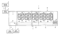
- FIG. 1 is a block diagram showing a configuration of an endoscopic form detection device according to a first embodiment of the present invention
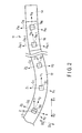
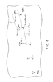
- FIG. 2 is a schematic view showing a configuration of an inserting section of an endoscope according to the first embodiment
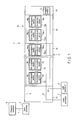
- FIG. 3 is a block diagram showing a configuration of a personal computer of the endoscopic form detection device according to the first embodiment
- FIG. 4 is a flowchart showing a method of detecting a form of the inserting section of an endoscope in a stationary state according to the first embodiment
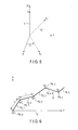
- FIG. 5 is a schematic view showing a global coordinate system and a correction coordinate system of the endoscopic form detection device according to the first embodiment in comparison with each other;
- FIG. 6 is a schematic view showing tentative positions of respective sensor units detected by a sensor tentative position detecting section of the endoscopic form detection device according to the first embodiment
- FIG. 7 is a schematic view explaining processing in a tentative link moving section of the sensor tentative position detecting section according to the first embodiment
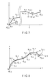
- FIG. 8 is a schematic view showing a tentative curve form of the inserting section of an endoscope detected by a tentative curve form detecting section of the endoscopic form detection device according to the first embodiment
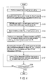
- FIG. 9 is a flowchart showing a method of detecting the tentative curve form by the tentative curve form detecting section according to the first embodiment
- FIG. 10 is a schematic view explaining processing in the tentative curve form detecting section according to the first embodiment
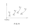
- FIG. 11 is a schematic view showing final positions of the respective sensor units corrected by a sensor position correcting section of the endoscopic form detection device according to the first embodiment
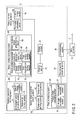
- FIG. 12 is a flowchart showing a method of correcting a position of each sensor unit by the sensor position correcting section according to the first embodiment
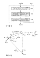
- FIG. 13 is a schematic view explaining processing in a sensor position sequentially compensating section of the sensor position correcting section according to the first embodiment
- FIG. 14 is a schematic view explaining processing in a sensor moving section and a post-movement arc forming section of the sensor position sequentially compensating section according to the first embodiment
- FIG. 15 is a schematic view explaining processing in an uncompensated sensor group moving section of the sensor position correcting section according to the first embodiment
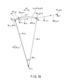
- FIG. 16 is a schematic view showing a final curve form of the inserting section of the endoscope detected by the final curve form detecting section of the endoscope form detection device according to the first embodiment
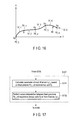
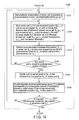
- FIG. 17 is a flowchart showing a method of detecting the final curve form by the final curve form detecting section according to the first embodiment
- FIG. 18 is a schematic view explaining processing in the final curve form detecting section according to the first embodiment.
- FIG. 19 is a flowchart showing a method of correcting positions of respective sensor units by a sensor position correcting section of an endoscopic form detection device according to a second embodiment of the present invention.
- FIG. 1 to FIG. 18 A first embodiment according to the present invention will now be described with reference to FIG. 1 to FIG. 18 .
- FIG. 1 is a view showing an endoscopic form detection device 1 according to a first embodiment.
- an endoscope 10 of the endoscopic form detection device 1 includes an inserting section 11 configured to be inserted into a body cavity and an operating section 12 provided to a proximal end side of the inserting section 11 .
- the inserting section 11 includes a distal-end hard section 14 provided at a most distal end side; a bending section 16 provided to the proximal end side of the distal-end hard section 14 , and an elongated flexible tube section 18 provided to the proximal end side of the bending section 16 .
- An imaging element 20 such as a CCD configured to image a subject is provided in the distal-end hard section 14 .
- One end of an imaging signal line 21 is connected to the imaging element 20 .
- the imaging signal line 21 is extended to the outside of the endoscope 10 from the operating section 12 through the inserting section 11 , and the other end of the imaging signal line 21 is connected to a video processor 3 which is an image processing unit.
- a light guide 23 configured to guide illumination light applied to a subject is extended to an illumination window (not shown) of the distal-end hard section 14 along longitudinal directions in the inserting section 11 .
- the light guide 23 is extended to the outside of the endoscope 10 from the operating section 12 and connected to a light source unit 4 .
- each of four bending operation wires (not shown) as bending operation transmission members is connected to a distal end portion of the bending section 16 in the inserting section 11 .
- the other end of each bending operation wire is connected to a bending operation knob (not shown), which is a bending operating section provided to the operating section 12 , through the flexible tube section 18 .
- the bending operation wires move in the longitudinal directions by operations using the bending operation knob.
- the bending section 16 is configured to bend in up-down directions and left-right directions of the endoscope 10 by the movement of the bending operation wires.
- a plurality of (N+1 in this embodiment) sensor units S 0 to S N are provided in the inserting section 2 .
- the sensor unit S 0 provided on a most proximal end side is arranged in a proximal end portion of the flexible tube section 18
- the sensor unit S N provided on the most distal end side is arranged in the distal end portion of the bending section 16 .
- Each sensor unit S i includes an accelerator sensor A i configured to measure acceleration, and a geomagnetic sensor B i configured to measure earth magnetism.
- FIG. 2 is a view showing the inserting section 11 of the endoscope 10 .
- each sensor unit S i has a local coordinate system C i (indicated by a dotted line in FIG. 2 ) having an origin at the center of the sensor unit S i , and also having an X i axis, a Y i axis, and a Z i axis.
- the X i axis directions coincide with the left-right directions of the endoscope 10 at the center of the sensor unit S i
- a right direction of the endoscope 10 as seen from the proximal end side is determined to be positive.
- the Y i axis directions coincide with the longitudinal directions at the center of the sensor unit S i , and the distal end side direction is determined to be positive.
- the Z i axis directions coincide with the up-down directions of the endoscope 10 at the center of the sensor unit S i , and an up direction of the endoscope 10 is determined to be positive.
- the acceleration sensor Ai is configured to measure an X i axis directions component, a Y i axis directions component, and a Z i axis directions component of acceleration at the origin of the local coordinate system C i .
- a global coordinate system C (indicated by a solid line in FIG. 2 ) having an X axis, a Y axis, and a Z axis is defined with the center of the sensor unit S 0 provided on the most proximal end side being determined as an origin.
- the global coordinate system C is a rectangular Cartesian coordinate system for a right-hand system with the center of the sensor unit S 0 provided on the most proximal end side determined as an origin.
- the X-axis directions coincide with predetermined directions (directions parallel to arrows D 1 and D 2 in FIG. 2 in this embodiment) perpendicular to vertical directions in which gravity functions, and a direction of the arrow D 1 in FIG.
- the Y axis directions coincide with directions (directions parallel to arrows E 1 and E 2 in FIG. 2 in this embodiment) perpendicular to the vertical directions and the X axis directions, and a direction of the arrow E 1 in FIG. 2 is determined to be positive.
- the Z axis directions coincide with the vertical directions, and an up direction (direction extending from a back side to a front side of a paper sheet) of the vertical directions is determined to be positive. It is to be noted that a positive direction of the X axis directions of the global coordinate system is determined as a magnetic north direction for convenience of explanation.
- Each local coordinate system C i is a coordinate system obtained by rotating the global coordinate system C ⁇ i about the X axis, ⁇ i about the Y axis, and ⁇ i about the Z axis and parallel translating the origin from the center of the sensor unit S 0 provided on the most proximal end side to the center of the sensor unit S i .
- ⁇ i is referred to as a pitch angle
- ⁇ i is referred to as a roll angle
- ⁇ i is referred to as a yaw angle
- three angles, i.e., the pitch angle ⁇ i , the roll angle ⁇ i , and the yaw angle ⁇ i will be generically referred to as posture angles.
- a clockwise direction of each posture angle ⁇ i , ⁇ i , or ⁇ i seen from a negative direction of each of the X axis, the Y axis, and the Z axis is determined to be positive.
- a posture of the sensor unit S i can be detected by calculating values of the posture angles ⁇ i , ⁇ i , and ⁇ i .
- a serial bus 5 such as I 2 C is connected to the acceleration sensor A i and the geomagnetic sensor B i of each sensor unit S i .
- the serial bus 5 is extended to the outside of the endoscope 10 from the operating section 12 through the inside of the inserting section 11 , and its proximal end is connected to a serial converter 6 .
- the serial converter 6 is configured to convert a serial signal of measurement data input from each sensor unit S i through the serial bus 5 into a USB signal.
- One end of a USB cable 7 is connected to the serial converter 6 .
- the other end of the USB cable 7 is connected to a personal computer 8 .
- the USB signal of the measurement data in each sensor unit S i is configured to be input to the personal computer 8 from the serial converter 6 .
- FIG. 3 is a view showing a configuration of the personal computer 8 .
- the personal computer 8 includes a communicating section 26 connected to the serial converter 6 through the USB cable 7 .
- the communicating section 26 is configured to receive the measurement data in each sensor unit S i .
- a physical quantity converting section 28 is connected to the communicating section 26 .
- the physical quantity converting section 28 is configured to convert the measurement data in each sensor unit S i received by a communicating section 26 into a physical quantity by using an offset, a gain, and others.
- a posture detecting section 30 is connected to the physical quantity converting section 28 .
- the posture detecting section 30 is configured to detect a posture of each sensor unit S i based on the measurement data in each sensor unit S i .
- the posture detecting section 30 includes a posture angle calculating section 32 configured to calculate the three posture angles ⁇ i , ⁇ i , and ⁇ i as rotational angles in the local coordinate system C i of each sensor unit S i about the X axis, the Y axis, and the Z axis from the global coordinate system C based on measurement data obtained by the acceleration sensor A i and the geomagnetic sensor B i of each sensor unit S i .
- the posture angle calculating section 32 includes a first angle calculating section 34 configured to calculate a pitch angle ⁇ i as a rotational angle in the local coordinate system C i of each sensor unit S i about the X axis from the global coordinate system C and a roll angle ⁇ i as a rotational angle in the local coordinate system C i of each sensor unit S i about the Y axis from the global coordinate system C based on measurement data in the acceleration sensor A i and the geomagnetic sensor Bi of each sensor unit S i .
- the posture angle calculating section 32 also includes a second angle calculating section 36 configured to calculate a yaw angle ⁇ i as a rotational angle in the local coordinate system C i of each sensor unit S i about the Z axis from the global coordinate system C based on the geomagnetic data in the geomagnetic sensor B i of each sensor unit S i .
- FIG. 4 is a flowchart showing a form detecting method of the inserting section 11 in a stationary state in which the inserting section 11 of the endoscope 10 is stopped.
- each sensor unit S i first performs measurement (a step S 101 ), and the posture detecting section 30 acquires measurement data in each sensor unit S i .
- the posture angle calculating section 32 calculates the three posture angles ⁇ i , ⁇ i , and ⁇ i in the local coordinate system C i of each sensor unit S i .
- the first angle calculating section 34 first calculates the pitch angle ⁇ i and the roll angle ⁇ i in the local coordinate system C i of each sensor unit S i (a step S 102 ) based on the measurement data in the acceleration sensor A i of each sensor unit S i .
- the posture angles ⁇ i , ⁇ i , and ⁇ i are determined as a (Z, X, Y) type that rotates in the order of the yaw angle ⁇ i , the pitch angle ⁇ i , and the roll angle ⁇ i . Therefore, a rotation matrix from the global coordinate system C to the local coordinate system C i is as follows:
- an X axis directions component, a Y axis directions component, and a Z axis directions component of an acceleration vector in the global coordinate system C are as follows:
- an X i axis directions component, a Y i axis directions component, and a Z i axis directions component of an acceleration vector in the local coordinate system C i measured by the acceleration sensor Ai are as follows:
- the local coordinate system C i is a coordinate system obtained by rotating the global coordinate system C in the order of the yaw angle ⁇ i , the pitch angle ⁇ i , and the roll angle ⁇ i . Therefore, based on Expression (1) to Expression (3), acceleration components observed in the local coordinate system C i are as follows:
- ⁇ i tan - 1 ( - a Bi_Y a Bi_X 2 + a Bi_Z 2 ) ( 7 )
- ⁇ i tan - 1 ⁇ ( - a Bi_X a Bi_Z ) ( 8 )
- the roll angle ⁇ i in the local coordinate system C i can be derived. As described above, based on measurement data in each acceleration sensor A i , the pitch angle ⁇ i and the roll angle ⁇ i in the local coordinate system C i can be calculated.
- the second angle calculating section 36 calculates the yaw angle ⁇ i in the local coordinate system C i of each sensor unit Si based on measurement data obtained by the geomagnetic sensor B i of each sensor unit S i (a step S 103 ).
- a corrected coordinate system C′ i obtained by correcting the rotation from the global coordinate system C about the X axis and the rotation from the global coordinate system C about the Y axis in each local coordinate system C i is defined by using the pitch angle ⁇ i and the roll angle ⁇ i calculated at the step S 102 .
- FIG. 5 is a view showing the global coordinate system C (indicated by a solid line in FIG.
- the corrected coordinate system C′ i obtained by correcting the rotation about the X axis and the rotation about the Y axis is a coordinate system obtained by rotating the global coordinate system C by the yaw angle ⁇ i about the Z axis and has an X′ i axis, a Y′ i axis, and a Z′ i axis.
- X′ i directions and Y′ i axis directions coincide with directions rotated by the yaw angle ⁇ i about the Z axis from the X axis directions and the Y axis directions in the global coordinate system C, respectively.
- Z′ i axis directions coincide with the vertical directions, i.e., the Z axis directions in the global coordinate system C.
- a positive direction of the X′ i directions is a direction rotated by the yaw angle ⁇ i about the Z axis from the magnetic north direction.
- an X i axis directions component, a Y i axis directions component, and a Z i axis directions component of a geomagnetic vector in the local coordinate system C i measured by the geomagnetic sensor B i are as follows:
- the corrected coordinate system C′ i is a coordinate system obtained by correcting the rotation from the global coordinate system C about the X axis and the rotation from the global coordinate system C about the Y axis in the local coordinate system C i . Therefore, based on R xi and R yi in Expression (1) and Expression (9), an X′ i axis directions component, a Y′i axis directions component, and a Z′ i axis directions component in the corrected coordinate system C′ i of a geomagnetic vector measured by the geomagnetic sensor B i are as follows:
- M Xi ′ M Xi cos ⁇ i +M Zi sin ⁇ i (11.1)
- a geomagnetic component on a horizontal plane (an X′ i ⁇ Y′ i plane in the corrected coordinate system C′ i ) perpendicular to the vertical directions directs the magnetic north direction. Therefore, based on Expression (11.2) and Expression (11.2), an angle ⁇ i from the X′ i axis to the magnetic north direction can be obtained by using the X′ i axis component and the Y′ i axis component of the geomagnetic vector in the corrected coordinate system C′ i . That is, the following expression can be obtained:
- the corrected coordinate system C′ i is a coordinate system obtained by rotating the global coordinate system C the yaw angle ⁇ i about the Z axis. Therefore, the angle ⁇ i obtained based on Expression (12) is the yaw angle ⁇ i in the local coordinate system C i when the global coordinate system C is determined as a reference.
- the X axis directions component, the Y axis directions component, and the Z axis directions component of the geomagnetic vector in the global coordinate system C can be obtained by using a geomagnetic sensor which is of the same type as the geomagnetic sensor B i to conduct the measurement in a state in which the X axis directions, the Y axis directions, and the Z axis directions in the global coordinate system C coincide with axis directions. Further, based on Expression (13), an angle ⁇ from the X axis to the magnetic north direction is obtained by using the X axis component and the Y axis component of the geomagnetic vector in the global coordinate system C. That is, the following expression can be acquired:
- the corrected coordinate system C′ i is a coordinate system obtained by rotating the global coordinate system C by the yaw angle ⁇ i about the Z axis. Therefore, based on Expression (12) and Expression (14), the following representation can be achieved:
- the posture detecting section 30 is configured to detect a posture of each sensor unit S i .
- FIG. 6 is a view showing tentative positions P 0, i of respective sensor units S i detected by the sensor tentative position detecting section 40 from a negative direction toward a positive direction of the global coordinate system C.
- a kth tentative link T 0, k from the proximal end side is a tentative link T 0, k between a kth sensor unit S k ⁇ 1 from the proximal end side and a (k+1)th sensor unit S k from the proximal end side.
- the sensor tentative position detecting section 40 includes a tentative link forming section 41 configured to form each tentative link T 0, j , and a tentative link moving section 42 configured to parallel translate each tentative link T 0, j formed by each tentative link forming section 41 .
- the tentative link forming section 42 is configured to parallel translate each tentative link T 0, j in such a manner that tentative link boundaries between each tentative link T 0, j and adjacent tentative links T 0, j ⁇ 1 and T 0, j+1 become continuous.
- a tentative linear form 71 is formed on the assumption that a form between the respective sensor units S i is a linear tentative link T 0, j .
- the tentative link forming section 41 is configured to first form each tentative link T 0, j having a linear form based on values of the posture angles ⁇ i , ⁇ i , and ⁇ i calculated at the steps S 102 and S 103 .
- Posture angles ⁇ k ⁇ 1 , ⁇ k ⁇ 1 , and ⁇ k ⁇ 1 in a local coordinate system C k ⁇ 1 are calculated at the steps S 102 and 103 by using expressions obtained by substituting i in Expression (7), Expression (8), and Expression (12) (or Expression (15)) by k ⁇ 1.
- a vector extending from the sensor unit S k ⁇ 1 toward the sensor unit S k is obtained by using the posture angles ⁇ k ⁇ 1 , ⁇ k ⁇ 1 , and ⁇ k ⁇ 1 and the inter-sensor dimension l which is an interval between respective sensor units S i .
- the vector extending from the sensor unit S k ⁇ 1 toward the sensor unit S k is represented as follows:
- l xk , l yk , and l zk are components obtained by dividing a vector having a magnitude l in the Y k ⁇ 1 axis directions in the local coordinate system C k ⁇ 1 to the X axis directions, the Y axis directions, and the Z axis directions in the global coordinate C.
- the tentative link T 0, k is formed by each vector calculated based on Expression (16.1).
- each tentative link T 0, j other than the tentative link T 0, k is likewise formed by the tentative link forming section 41 . That is, a vector from the sensor unit S j ⁇ 1 on the proximal end side (a side close to the origin of the global coordinate system C) of the tentative link T 0, j to the sensor unit S j on the distal end side (a side far from the origin of the global coordinate system C) of the tentative link T 0, j is obtained. Further, the tentative link T 0, j is formed by using the vector from the sensor unit S j ⁇ 1 to the sensor unit S j .
- the tentative link forming section 41 is configured to form the tentative link T 0, j on the assumption that the tentative link T 0, j is extended from the center of the sensor unit S j ⁇ 1 on the proximal end side (the side close to the origin of the global coordinate system C) to the center of the sensor unit S j on the distal end side (the side far from the origin of the global coordinate system C) in longitudinal directions at the center of the sensor unit S j ⁇ 1 on the proximal end side.
- the inter-sensor dimension l it is preferable for the inter-sensor dimension l to be approximately 50 mm. Increasing the inter-sensor dimension l enables reducing the number of the sensor units S i and also decreasing a cost. Furthermore, when the inter-sensor dimension l is smaller than approximately 50 mm, errors when detecting a form of the inserting section 11 can be reduced even if a form between the respective sensor units S i is assumed to be the linear tentative link T 0, j whose dimension is equal to the inter-sensor dimension l.
- the tentative link moving section 42 is configured to parallel translate each tentative link T 0, j formed by the tentative link forming section 41 in such a manner that tentative link boundaries between each tentative link T 0, j and adjacent tentative likes T 0, j ⁇ 1 and T 0, j+1 become continuous.
- FIG. 7 is a view explaining processing in the tentative link moving section 42 .
- description will be given as to movement of the kth tentative link T 0, k from the proximal end side between the kth sensor unit S k ⁇ 1 from the proximal end side and the (k+1)th sensor unit S k from the proximal end side.
- the tentative link moving section 42 is configured to parallel translate the tentative link T 0, k a distance from the origin to a distal end of the tentative link movement completed portion 73 (i.e., a tentative position P 0, k ⁇ 1 of the sensor unit S k ⁇ 1 ). That is, the tentative link T 0, k is parallel translated from a position indicated by a dotted line in FIG. 7 to a position indicated by a solid line in FIG. 7 . As a result, a boundary between the tentative link T 0, k ⁇ 1 and the tentative link T 0, k becomes continuous.
- the tentative link moving section 42 likewise moves each tentative link T 0, j other than the tentative link T 0, k . That is, when moving the tentative link T 0, j , the tentative link moving section 42 is configured to parallel translate the tentative link T 0, j a distance from the origin to the distal end of the tentative link movement completed portion 73 (an end on the side far from the origin in the global coordinate system C). As a result, a tentative link boundary between the tentative link T 0, j and a tentative link T 0, j ⁇ 1 adjacent to a proximal end side (the side close to the origin in the global coordinate system C) of the tentative link T 0, j becomes continuous.
- the movement is not carried out.
- the tentative linear form 71 is formed on the assumption that a form between the respective sensor units S i is the linear tentative link T 0, j , as shown in FIG. 6 .
- Positions of the respective sensor units S i in the tentative linear form 71 are detected as tentative positions P 0, i of the respective sensor units S i (the step S 104 ).
- the sensor tentative position detecting section 40 is connected to a tentative curve form detecting section 50 .
- the tentative curve form detecting section 50 is configured to perform curve interpolation on the assumption that a form between tentative positions P 0, i of the respective sensor units S i detected by the sensor tentative position detecting section 40 is a tentative arc L 0.j , thereby detecting a tentative curve form 75 .
- FIG. 8 is a view showing the tentative curve form 75 of the inserting section 11 of the endoscope 10 detected by the tentative curve form detecting section 50 from the negative direction toward the positive direction of the Z axis in the global coordinate C. As shown in FIG.
- the tentative curve form detecting section 50 is configured to carry out the curve interpolation between the tentative positions P 0, i of the respective sensor units S i in the tentative linear form 71 indicated by a dotted line in FIG. 8 . As a result, each tentative arc L 0, j is formed, and the tentative curve form 75 indicated by a solid line in FIG. 8 is detected.
- the tentative curve form detecting section 50 includes a unit tangent vector calculating section 51 configured to calculate a unit tangent vector at a tentative position P 0, i of each sensor unit S i , a rate-of-change calculating section 52 configured to calculate a rate of change of the unit tangent vector between the tentative positions P 0, i of the respective sensor units S i based on the unit tangent vector calculated by the unit tangent vector calculating section 51 , and a tentative arc forming section 53 configured to form the tentative arc L 0, j between the tentative positions P 0, i of the respective sensor units S i based on the unit tangent vector calculated by the unit tangent vector calculating section 51 and the rate of change calculated by the rate-of-change calculating section 52 .
- the tentative curve form 75 is detected.
- the tentative curve form detecting section 50 is configured to carry out the curve interpolation between the tentative positions P 0, i of the respective sensor units S i detected at the step S 104 by using the tentative curve L 0, j , thereby detecting the tentative curve form 75 (a step S 105 ).
- the inter-sensor dimension l is smaller than approximately 50 mm, an error when detecting a form of the inserting section 11 is reduced even though a form between the respective sensor units S i is assumed to be a linear tentative link T 0, j whose dimension is equal to the inter-sensor dimension l.
- a form of the inserting section 11 of the endoscope 10 when inserted into a body cavity is a curve form. Therefore, performing the curve interpolation between the tentative positions P 0, i of the respective sensor units S i is important.
- the inserting section 11 of the endoscope 10 has appropriate elasticity. Therefore, a curvature of the curved form of the inserting section 11 varies only slightly.
- the tentative curve form detecting section 50 is configured to sequentially carry out the curve interpolation in accordance with each portion between the tentative positions P 0, i of the respective sensor units S i to form the tentative curve L 0, j .
- description will be given as to a method of performing the curve interpolation between the tentative positions P 0, j of the respective sensor units S i .
- the curve interpolation between a kth sensor unit S k ⁇ 1 from the proximal end side and a (k+1)th sensor unit S k from the proximal end side will be explained. That is, a space between the tentative position P 0, k ⁇ 1 and the tentative position P 0, k is an interpolation target space between tentative positions as an interpolation target.
- FIG. 9 is a flowchart showing a method of using the tentative curve form detecting section 50 to detect the tentative curve form 75 .
- FIG. 10 is a view explaining processing in the tentative curve form detecting section 50 .
- the unit tangent vector calculating section 51 is configured to first calculate a unit tangent vector at the tentative position P 0, k ⁇ 1 of the sensor unit S k ⁇ 1 and a unit tangent vector at the tentative position P 0, k of the sensor unit S k (a step S 111 ).
- the unit tangent vector at the tentative position P 0, k ⁇ 1 of the sensor unit S k ⁇ 1 is represented as follows:
- the unit tangent vector at the tentative position P 0, k ⁇ 1 is a unit vector of a vector from the tentative position P 0, k ⁇ 1 to the tentative position P 0, k .
- the unit tangent vector of the sensor unit S k at the tentative position P 0, k can be calculated by using expressions obtained by substituting k in Expression (17.1), Expression (17.2), and Expression (17.3) by k+1. That is, the unit tangent vector at the tentative position P 0, k is a unit vector of a vector from the tentative position P 0, k to the tentative position P 0, k+1 .
- the rate-of-change calculating section 52 is configured to calculate a rate of change of the unit tangent vector between the tentative position P 0, k ⁇ 1 of the sensor unit S k ⁇ 1 and the tentative position P 0, k of the sensor unit S k based on the unit tangent vector calculated by the unit tangent calculating section 51 (a step S 112 ).
- a rate-of-change vector of the unit tangent vector between the tentative position P 0, k ⁇ 1 and the tentative position P 0, k is obtained based on the following expressions:
- a magnitude of the rate-of-change vector obtained based on Expression (18.1) and Expression (18.2) is the rate of change of the unit tangent vector between the tentative position P 0, k ⁇ 1 and the tentative position P 0, k .
- the tentative arc forming section 53 is configured to form the tentative arc L 0, k between the tentative position P 0, k ⁇ 1 of the sensor unit S k ⁇ 1 and the tentative position P 0, k of the sensor unit S k based on the unit tangent vector calculated by the unit tangent vector calculating section 51 and the rate of change calculated by the rate-of-change calculating section 52 (a step S 113 ).
- the rate of change of the unit tangent vector between the tentative position P 0, k ⁇ 1 and the tentative position P 0, k calculated at the step S 112 is curvature 1/R 0, k of the tentative arc L 0, k . Since a radius R 0, k of the tentative arc L 0, k is an inverse number of the curvature 1/R 0, k , the radius R 0, k of the tentative arc L 0, k is as follows:
- a position of the center O 0, k of the tentative arc L 0, k in the global coordinate C can be obtained based on the following expression:
- a central angle ⁇ 0, k of the tentative arc L 0, k can be obtained by using the unit tangent vector at the tentative position P 0, k ⁇ 1 and the unit tangent vector at the tentative position P 0, k based on the following expression:
- each tentative arc L 0, j other than the tentative arc L 0, k can be likewise formed by performing the curve interpolation between a tentative position P 0, j ⁇ 1 and a tentative position P 0, j . That is, when forming the tentative arc L 0, j , the unit tangent vector calculating section 51 is configured to first calculate a unit tangent vector at the tentative position P 0, j ⁇ 1 of the sensor unit S j ⁇ 1 placed on the proximal end side (the side close to the origin in the global coordinate system C) in the interpolation target space between the tentative positions and a unit tangent vector at the tentative position P 0, j of the sensor unit S j placed on the distal end side (the side far from the origin of the global coordinate system C) the interpolation target space between the tentative positions.
- the unit tangent vector at the tentative position P 0, j ⁇ 1 of the sensor unit S j ⁇ 1 can be calculated by using expressions obtained by substituting j for k in Expression (17.1), Expression (17.2), and Expression (17.3), and it is a unit vector of a vector from the tentative position P 0, j ⁇ 1 to the tentative position P 0, j . Further, the unit tangent vector at the tentative position P 0, j of the sensor unit S j can be calculated by using expressions obtained by substituting j+1 for k in Expression (17.1), Expression (17.2), and Expression (17.3), and it is a unit vector of a vector from the tentative position P 0, j to the tentative position P 0, j+1 . As a result, a unit tangent vector at the tentative position P 0, i of each sensor unit S i can be calculated (a step S 111 ).
- the rate-of-change calculating section 52 is configured to calculate a rate of change of the unit tangent vector in the interpolation target space between the tentative positions corresponding to a portion between the tentative position P 0, j ⁇ 1 of the sensor unit S j ⁇ 1 and the tentative position P 0, j of the sensor unit S j .
- the rate of change of the unit tangent vector between the tentative position P 0, j ⁇ 1 and the tentative position P 0, j can be calculated by using expressions obtained by substituting j for k in Expression (18.1) and Expression (18.2). As a result, the rate of change of the unit tangent vector between the tentative positions P 0, i of the respective sensor units S i can be detected (a step S 112 ).
- the tentative arc forming section 53 is configured to form the tentative arc L 0, j in the interpolation target space between the tentative positions, namely, between tentative position P 0, j ⁇ 1 of the sensor unit S j ⁇ 1 and the tentative position P 0, j of the sensor unit S j .
- a radium R 0, j , a center O 0, j , and a central angle ⁇ 0, j of the tentative arc L 0, j can be calculated by using expressions obtained by substituting j for k in Expression (19), Expression (20), and Expression (21).
- the tentative arc L 0, j between the tentative positions P 0, i of the respective sensor units S i is formed (a step S 113 ).
- the curve interpolation is carried out between the tentative positions P 0, i of all the sensor units S i , and then all the tentative arcs L 0, j are formed, thereby detecting the tentative curve form 75 .
- the tentative curve form detecting section 50 is connected to a sensor position correcting section 55 configured to correct a position of each sensor unit S i .
- the sensor position correcting section 55 is configured to correct a position of each sensor unit S i based on an absolute value of a difference between an arc length R 0, j ⁇ 0, j of each tentative arc L 0, j of the tentative curve form 75 detected by the tentative curve form detecting section 50 and the inter-sensor dimension l.
- the absolute value of the difference between the arc length R 0, j ⁇ 0, j of each tentative arc L 0, j and the inter-sensor dimension l is assumed to be energy E 0, j .
- FIG. 11 is a view showing a position of each sensor unit S i corrected by the sensor position correcting section 55 from the negative direction toward the positive direction of the Z axis of the global coordinate C.
- the sensor position correcting section 55 is configured to correct each sensor unit S i from a tentative position P 0, i to a final position P F, i .
- the sensor position correcting section 55 includes a sensor position sequentially compensating section 57 configured to sequentially perform positional compensation from the sensor unit S i provided on the proximal end side (the side close to the origin of the global coordinate system C). In a state before the sensor position sequentially compensating section 57 performs the positional compensation of each sensor unit S i , each sensor unit S i has been moved from the tentative position P 0, i to a pre-compensation position Q 0, i (details will be described later).
- the sensor position sequentially compensating section 57 is configured to perform the positional compensation with respect to each sensor unit S i from the pre-compensation position Q 0, i to the final position P F, i .
- the sensor position correction section 55 includes an uncompensated sensor group moving section 59 configured to parallel translate an uncompensated sensor group 77 , that includes the sensor units Si which have not been subjected to the positional compensation, every time the sensor position sequentially compensating section 57 performs the positional compensation of one sensor unit S i .
- the sensor position sequentially compensating section 57 is configured to perform the positional compensation from the pre-compensation position Q 0, i to the final position P F, i of each of all the sensor units S i .
- the pre-compensation position Q 0, i is a position of each sensor unit S i immediately before performing the positional compensation by the sensor position sequentially compensating section 57 .
- the uncompensated sensor group moving section 59 is configured to parallel translate the uncompensated sensor group 77 a distance corresponding to a compensation amount from the pre-compensation position Q 0, i to the final position P F, i of an immediately preceding compensation target sensor 79 which is the sensor unit S i as a compensation target in immediately preceding positional compensation effected by the sensor position sequentially compensating section 57 .
- a represents the number of times that each sensor unit S i is parallel translated by the uncompensated sensor group moving section 59 .
- a pre-parallel-translation position U 0, i of the first parallel translation of each sensor unit S i performed by the uncompensated sensor group moving section 59 coincides with the tentative position P 0, i .
- Each sensor unit S i is parallel translated for (i ⁇ 1) times by the uncompensated sensor group moving section 59 .
- a post-parallel-translation position U i ⁇ 1, i of each sensor unit S i in (i ⁇ 1)th parallel translation carried out by the uncompensated sensor group moving section 59 coincides with the pre-compensation position Q 0, i .
- a position of each sensor unit S i is corrected from the tentative position P 0, i to the final position P F, i based on the positional compensation by the sensor position sequentially compensating section 57 and the parallel translation by the uncompensated sensor group moving section 59 .
- t represents the number of times that each sensor unit S i is moved by the sensor moving section 61 .
- the sensor position sequentially compensating section 57 includes a post-movement arc forming section 62 configured to perform curve interpolation between a final position P F, i of a close-side adjacent sensor 82 , that is a sensor unit Si provided to be adjacent to the proximal end side (the side close to the origin of the global coordinate system C) with respect to the compensation target sensor 81 , and a post-movement position Q t, i of the compensation target sensor 81 .
- the sensor position sequentially compensating section 57 includes a movement controlling section 63 configured to control the sensor moving section 61 to repeatedly move the compensation target sensor 81 from the pre-movement position Q t-1, i to the post-movement position Q t, i until an absolute value of a difference between an arc length R t, j ⁇ t, j of a post-movement arc L t, j formed by the post-movement arc forming section 62 and the inter-sensor dimension l becomes not greater than a predetermined threshold value.
- the sensor position sequentially compensating section 57 includes a final position deciding section 64 configured to decide a post-movement position Q F, i in the last (e.g., Fth) movement by the sensor moving section 61 as a final position P F, i of the compensation target sensor 81 .
- a final position deciding section 64 configured to decide a post-movement position Q F, i in the last (e.g., Fth) movement by the sensor moving section 61 as a final position P F, i of the compensation target sensor 81 .
- the sensor position correcting section 55 is configured to correct a position of each sensor unit S i based on an absolute value of a difference between an arc length R 0, j ⁇ 0, j of each tentative arc L 0, j of the tentative curve form 75 detected by the tentative curve form detecting section 50 and the inter-sensor dimension l (a step S 106 ). That is, the position of each sensor unit S i is corrected based on energy E 0, j obtained by the following expression:
- each sensor unit S i is corrected from the tentative position P 0, i to the final position P F, i .
- the tentative curve form detecting section 50 forms the tentative curve form 75 having a small error from an actual curve form of the inserting section 11 .
- the tentative curve form detecting section 50 does not perform the curve interpolation between the respective sensor units S i while considering the inter-sensor dimension l.
- measurement data of each sensor unit S i has an error due to noise and other factors. Therefore, it is important to correct a position of each sensor unit S i based on the absolute value of a difference between the arc length R 0, j ⁇ 0, j of each tentative arc L 0, j and the inter-sensor dimension l while considering the inter-sensor dimension l.
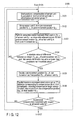
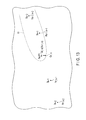
- FIG. 12 is a flowchart showing a method of correcting a position of each sensor unit S i by the sensor position correcting section 55 .
- FIG. 13 is a view explaining processing carried out by the sensor position sequentially compensating section 57 .
- the sensor position sequentially compensating section 57 is configured to sequentially carry out the positional compensation from the pre-compensation position Q 0, i before the positional compensation to the final position P F, i of each of the sensor units S i starting from the sensor unit S i provided on the proximal end side (the side close to the origin of the global coordinate system C).
- the pre-compensation position Q 0, i is a position of each sensor unit S i immediately before the positional compensation is performed by the sensor position sequentially compensating section 57 , and it is a position provided when each sensor unit S i is parallel translated from the tentative position P 0, i for (i ⁇ 1) times by the uncompensated sensor group moving section 59 .
- the sensor position sequentially compensating section 57 is configured to start the positional compensation of the sensor unit S i provided on the most proximal end side in the uncompensated sensor group 77 (a step S 121 ). That is, as shown in FIG.
- the sensor position sequentially compensating section 57 is configured to start the positional compensation to the final position P F, k of the sensor unit S k provided on the most proximal end side in the uncompensated sensor group 77 . That is, the sensor unit S k is the compensation target sensor 81 as a positional compensation target. It is to be noted that the positional compensation of the (k+1)th sensor unit S k from the proximal end side will be described.
- the positional compensation from the pre-compensation position Q 0, i to the final position P F, i is completed from the first sensor unit to the sensor unit S k ⁇ 1 .
- the sensor unit S k is placed at a pre-compensation position Q 0, k .
- the sensor moving section 61 is configured to move the sensor unit S k from the position Q 0, k to a position Q 1, k (a step S 122 ), whereby the sensor unit S k is moved for the first time.
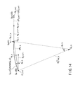
- FIG. 14 is a view explaining processing in the sensor moving section 61 and the post-movement arc forming section 62 .
- the sensor unit S k as the compensation target sensor 81 moves from a pre-movement position Q s ⁇ 1, k to a post-movement position Q s, k . That is, the sensor unit S k moves from a pre-movement position Q t-1, k to a post-movement position Q t, k by the movement performed once by the sensor moving section 61 (the step S 122 ).
- the post-movement arc forming section 62 is configured to carry out the curve interpolation between a final position P F, k ⁇ 1 of the sensor unit S k ⁇ 1 provided to be adjacent to the proximal end side of the sensor unit S k and the post-movement position Q t, k of the sensor unit S k every time the sensor moving section 61 moves the sensor unit S k once, thereby forming a post-movement arc L t, k (a step S 123 ). As shown in FIG.
- the curve interpolation is carried out between the final position P F, k ⁇ 1 of the sensor unit S k ⁇ 1 and the post-movement position Q s, k of the sensor unit S k , thereby forming a post-movement arc L s, k .
- the sensor unit S k ⁇ 1 is the close-side adjacent sensor 82 provided to be adjacent to the side close to the origin of the global coordinate system C with respect to the sensor unit S k which is the compensation target sensor 81 .
- a unit tangent vector at the final position P F, k ⁇ 1 of the sensor unit S k ⁇ 1 and a unit tangent vector at the post-movement position Q s, k of the sensor unit S k are calculated.
- the unit tangent vector at the final position P F, k ⁇ 1 of the sensor unit S k ⁇ 1 is as follows:
- the unit tangent vector at the final position P F, k ⁇ 1 is a unit vector of a vector from the final position P F, k ⁇ 1 to the post-movement position Q s, k . Furthermore, when calculating the unit tangent vector at the post-movement position Q s, k , a sensor unit S k+1 which is a far-side adjacent sensor 83 provided to be adjacent to the side far from the origin of the global coordinate system C with respect to the sensor unit S k , which is the compensation target sensor 81 , is assumed to be arranged at a position Q′ s, k+1 .
- a vector from the post-movement position Q s, k to the position Q′ s, k+1 has a direction and a magnitude equal to those of a vector from a tentative position P 0, k of the sensor unit S k to a tentative position P 0, K+1 of the sensor unit S k .
- a unit vector at the post-movement position Q s, k of the sensor unit S k+1 is as follows:
- the unit tangent vector at the post-movement position Q s, k is a unit vector of a vector from the post-movement position Q s, k to the position Q′ s, k+1 of the sensor unit S k+1 . Therefore, the unit tangent vector at the post-movement position Q s, k has the same direction as the unit tangent vector obtained by substituting k+1 for k in Expression (17.1) to Expression (17.3).
- a rate of change of the unit tangent vector between the final position P F, k ⁇ 1 of the sensor unit S k ⁇ 1 and the post-movement position Q s, k of the sensor unit S k is calculated.
- a rate-of-change vector of the unit tangent vector between the final position P F, k ⁇ 1 and the post-movement position Q s, k is obtained based on the following expressions:
- a magnitude of the rate-of-change vector obtained based on Expression (25.1) and Expression (25.2) serves as a rate of change of the unit tangent vector between the final position P F, k ⁇ 1 and the post-movement position Q s, k .
- a post-movement arc L s, k is formed between the final position P F, k ⁇ 1 of the sensor unit S k ⁇ 1 and the post-movement position Q s, k of the sensor unit S k .
- the rate of change of the unit tangent vector between the final position P F, k ⁇ 1 and the post-movement position Q s, k calculated by using Expression (25.1) and Expression (25.2) is curvature 1/R s, k of the post-movement arc L s, k .
- a radius R s, k of the post-movement arc L s, k is an inverse number of the curvature 1/R s, k , and hence the radius R s, k of the post-movement arc L s, k is as follows:
- a position of a center O s, k of the post-movement arc L s, k can be obtained based on the following expression:
- a central angle ⁇ s, k of the post-movement arc Ls, k can be obtained by using the unit tangent vector at the final position P F, k ⁇ 1 and the unit tangent vector at the post-movement position Q s, k based on the following expression:
- the post-movement arc L s, k between the final position P F, k ⁇ 1 and the post-movement position Q s, k is formed by using these parameters.
- an absolute value of a difference between an arc length R t, k ⁇ t, k of the post-movement arc L t, k and the inter-sensor dimension l is calculated by the movement controlling section 63 (a step S 124 ).
- the absolute value of the difference between the arc length R t, k ⁇ t, k of the post-movement arc L t, k and the inter-sensor dimension l is assumed to be energy E t, k , and this energy can be provided by the following expression:
- the processing returns to the step S 122 , and the sensor moving section 61 is configured to further move the sensor unit S k from the position Q t, k .
- the sensor moving section 61 is configured to perform (s+1)th movement. Based on the (s+1)th movement, the sensor unit S k moves from the pre-movement position Q s, k to the post-movement position Q s+1, k .
- the sensor moving section 61 is controlled by the movement controlling section 63 to repeatedly perform the movement of the sensor unit S k as the compensation target sensor 81 from the pre-movement position Q t-1, k to the post-movement position Q t, k until the energy E t, k becomes equal to or below the predetermined threshold value.
- the processing advances to the next step.
- the final position deciding section 64 is configured to decide the post-movement position Q F, k in the last (e.g., fth) movement of the sensor unit S k by the sensor moving section 61 as the final position P F, k of the sensor unit S k (a step S 125 ), which is the compensation target sensor 81 . As described above, the positional compensation of the sensor unit S k from the pre-compensation position Q 0, k to the final position P F, k is completed.
- the sensor position sequentially compensating section 57 performs the positional compensation to the final position P i, k with respect to each sensor unit S i other than the sensor unit S k like the sensor unit S k . That is, the sensor moving section 61 is configured to move the sensor unit S i from a pre-movement position Q t-1, i to a post-movement position Q t, i (the step S 122 ).
- the post-movement arc forming section 62 is configured to perform the curve interpolation between a final position P F, i ⁇ 1 of a sensor unit S i ⁇ 1 , which is the close-side adjacent sensor 82 provided to be adjacent to the proximal end side of the sensor unit S i , and the post-movement position Qt, i of the sensor unit S i every time the sensor moving section 61 moves the sensor unit S i once, thereby forming a post-movement arc L t, j (the step S 123 ).
- the movement controlling section 63 is configured to calculate energy E t, j which is an absolute value of a difference between an arc length R t, j ⁇ t, j of the post-movement arc L t, j and the inter-sensor dimension l (the step S 124 ). If the energy E t, j is larger than a predetermined threshold value (the step S 124 —No), the processing returns to the step S 122 , and the sensor moving section 61 is configured to further move the sensor unit S i from the position Q t, i .
- the processing advances to the next step.
- the final position deciding section 64 is configured to decide a post-movement position Q F, i in the final movement of the sensor unit S i performed by the sensor moving section 61 as a final position P F, i of the sensor unit S i (the step S 125 ), which is the compensation target sensor 81 .
- the positional compensation of the sensor unit S i from the pre-compensation position Q 0, i to the final position P F, i is completed.
- the uncompensated sensor group moving section 59 is configured to parallel translate the uncompensated sensor group 77 , that includes sensor units S i which have not been subjected to the positional compensation, every time the sensor position sequentially compensating section 57 carries out the positional compensation of one sensor unit S i (a step S 126 ).
- FIG. 15 is a view explaining processing in the uncompensated sensor group moving section 59 . As shown in FIG.
- sensor units S k+1 to S N are the uncompensated sensor group 77 which has not been subjected to the positional compensation. Further, the sensor unit S k is the immediately preceding compensation target sensor 79 as a compensation target in the immediately preceding positional compensation carried out by the sensor position sequentially compensating section 57 .
- the uncompensated sensor group moving section 59 is configured to parallel translate the uncompensated sensor group 77 a distance corresponding to a compensation amount from the pre-compensation position Q 0, k to the final position P F, k of the sensor unit S k as the immediately preceding compensation target sensor 79 .
- each sensor unit S i in the uncompensated sensor group 77 moves from a pre-parallel-translation position U k ⁇ 1, i to a post-parallel-translation position U k, i .
- the pre-parallel-translation position U k ⁇ 1, i of each sensor unit S i in the uncompensated sensor group 77 is a position provided when each sensor unit S i is moved from a tentative position P 0, i for (k ⁇ 1) times by the uncompensated sensor group moving section 59 , and this parallel translation achieves k times of the parallel translation of each sensor unit S i in the uncompensated sensor group 77 by the uncompensated sensor group moving section 59 .
- a post-parallel-translation position U k, k+1 of the sensor unit S k+1 coincides with the pre-compensation position Q 0, k+1
- a vector from the final position P F, k of the sensor unit S k to the post-parallel-translation position U k, k+1 of the sensor unit S k+1 has a direction and a magnitude equal to those of a vector from the tentative position P 0, k of the sensor unit S k to the tentative position P 0, k+1 of the sensor unit S k+1 .
- the uncompensated sensor group 77 is parallel translated even in a state that the positional compensation of each sensor unit S i other than the sensor unit S k to the final position PF, i is completed, like the sensor unit S k . That is, the uncompensated sensor group moving section 59 is configured to translate the uncompensated sensor group 77 a distance corresponding to a compensation amount of the immediately preceding target sensor 79 from the pre-compensation position Q 0, i to the final position P F, i performed by the sensor position sequentially compensating section 57 (a step S 126 ). As a result, the uncompensated sensor group 77 is parallel translated from a pre-parallel-translation position U a ⁇ 1, i to a post-parallel-translation position U a, i .
- step S 127 whether the positional compensation is completed with respect to all the sensor units S i is confirmed.
- the processing advances to the next step.
- the processing returns to the step S 121 , and the sensor position sequentially compensating section 57 carries out the positional compensation of the sensor unit S i on the most proximal end side in the uncompensated sensor group 77 . That is, the steps S 121 to S 126 are repeatedly performed until the positional compensation is completed with respect to all the sensor units S i .
- a position of each sensor unit S i is corrected from the tentative position P 0, i to the final position P F, i .
- the sensor position correcting section 55 is connected to a final curve form detecting section 65 .
- the final curve form detecting section 65 is configured to carry out the curve interpolation between final positions P F, i of respective sensor units S i by using a final arc L F, j , thereby detecting a final curve form 85 of the inserting section 11 .
- FIG. 16 is a view showing the final curve form 85 of the inserting section 11 of the endoscope 10 detected by the final curve form detecting section 65 from the negative direction toward the positive direction of the Z axis of the global coordinate C. As shown in FIG.
- the final curve form detecting section 65 is configured to perform the curve interpolation between the final positions P F, i of the respective sensor units S i . As a result, each final arc L F, j is formed, and the final curve form 85 is detected.
- the final curve form detecting section 65 includes a parameter calculating section 67 configured to calculate a parameter of each final arc L F, j based on the final position P F, i of each sensor unit S i , and a final arc forming section 69 configured to form the final arc P F, i based on the parameter calculated by the parameter calculating section 67 .
- the final arc forming section 69 is configured to carry out the curve interpolation between the final positions P F, i of the respective sensor units S i at a constant angular velocity with respect to a change in parametric variable t based on an interpolation function L F, j (t) using a quaternion and the parametric variable t, thereby forming the final arc L F, j .
- a drawing section 45 is connected to the final curve form detecting section 65 .
- the final curve form 85 of the inserting section 11 in the global coordinate system C detected by the final curve form detecting section 65 is drawn by the drawing section 45 .
- An operator can confirm the final curve form 85 drawn by the drawing section 45 in a display section 47 .
- the final curve form detecting section 65 configured to perform the curve interpolation between the final positions P F, i of the respective sensor units S i which have been subjected to the positional correction at the step S 106 by using the final arc L F, j , thereby detecting the final curve form 85 (a step S 107 ).
- the curve interpolation is effected between the final positions P F, i of the respective sensor units S i while considering the inter-sensor dimension l, whereby the finial curve form 85 is detected with a high detection accuracy.
- the final curve form detecting section 65 is configured to sequentially carry out the curve interpolation between the final positions P F, i of the respective sensor units S i to form the final arc L F, j .
- description will now be given as to a method of performing the curve interpolation between the final positions P F, i of the respective sensor units S i by using the final curve form detecting section 65 .
- the curve interpolation between a kth sensor unit S k ⁇ 1 from the proximal end side and a (k+1)th sensor unit S k from the proximal end side will be explained. That is, a portion between the final position P F, k ⁇ 1 and the final position P F, k is an interpolation target space between final positions as an interpolation target.
- FIG. 17 is a flowchart showing a method of detecting the final curve form 85 by the final curve form detecting section 65 .
- FIG. 18 is a view explaining processing in the final curve form detecting section 65 .
- the parameter calculating section 67 is configured to first calculate a parameter of a final arc L F, k based on the final position P F, k ⁇ 1 and the final position P F, k (a step S 131 ).
- a unit tangent vector at the final position P F, k ⁇ 1 of the sensor unit S k ⁇ 1 and a unit tangent vector at the final position P F, k of the sensor unit S k are calculated.
- the unit tangent vector at the final position P F, k ⁇ 1 of the sensor unit S k ⁇ 1 is as follows:
- the unit tangent vector at the final position P F, k ⁇ 1 is a unit vector of a vector from the final position P F, k ⁇ 1 to the final position P F, k .
- the unit tangent vector at the final position P F, k of the sensor unit S k can be calculated by using expressions obtained by substituting k+1 for k in Expression (30.1), Expression (30.2), and Expression (30.3). That is, the unit tangent vector at the final position P F, k is a unit vector of a vector from the final position P F, k to the final position P F, k+1 .
- a rate of change in unit tangent vector between the final position P F, k ⁇ 1 of the sensor unit S k ⁇ 1 and the final position P F, k of the sensor unit S k is calculated.
- a rate-of-change vector of a unit tangent vector between the final position P F, k ⁇ 1 and the final position P F, k is obtained based on the following expressions:
- a magnitude of the rate-of-change vector obtained by Expression (31.1) and Expression (31.2) is a rate of change of the unit tangent vector between the final position P F, k ⁇ 1 and the final position P F, k .
- a position of a center O F, k of the final arc L F, k in the global coordinate C can be calculated by the following expression:
- a central angle ⁇ F, k of the final arc L F, k can be calculated based on the following expression:
- the parameter calculating section 67 can also calculate a parameter of each final arc L F, j other than the final arc L F, k by using expressions obtained by substituting j for k in Expression (30.1) to Expression (34), like the final arc L F, k . That is, based on the final position P F, i of each sensor unit S i , a parameter of each final arc L F, j is calculated (a step S 131 ).
- the final arc forming section 69 is configured to carry out the curve interpolation between the final positions P F, i of the respective sensor units S i to form each final arc L F, j (a step S 132 ).
- the final arc L F, j is formed based on an interpolation function using a quaternion and a parametric variable.
- the quaternion is a number obtained by expanding a complex number, and it can be represented by the following expression:
- a vector from the center O F, k of the final arc L F, k to the final position P F, k ⁇ 1 of the sensor unit S k ⁇ 1 is calculated.
- the vector from the center O F, k to the final position P F, k ⁇ 1 is as follows:
- a vector from the center O F, k of the final arc L F, k to the final position P F, k of the sensor unit S k is calculated.
- the vector from the center O F, k to the final position P F, k is as follows:
- an X axis directions component of the calculated vector in the global coordinate system C is a component of an imaginary number i of the quaternion.
- a Y axis directions component of the vector in the global coordinate system C is a component of an imaginary number j of the quaternion
- a Z axis directions component of the vector in the global coordinate system C is a component of an imaginary number k of the quaternion.
- the curve interpolation is effected between the final position P F, k ⁇ 1 of the sensor unit S k ⁇ 1 and the final position P F, k of the sensor unit S k to form the final arc L F, k .
- the curve interpolation is performed between the final position P F, k ⁇ 1 and the final position P F, k at a constant angular velocity with respect to a change in the parametric variable t. For example, a distance d 1 interpolated during a change of t from 0 to 0.1 is equal to a distance d 2 interpolated during a change of t from 0.5 to 0.6 (see FIG.
- each final arc L F, j other than the final arc L F, k is also formed using the interpolation function L F, j (t).
- the interpolation function L F, j (t) is calculated using expressions obtained by substituting j for k in Expression (37) to Expression (42).
- the curve interpolation is carried out between final positions P F, i of the respective sensor units S i at a constant angular velocity with respect to a change in the parametric variable of the interpolation function L F, j (t).
- step S 108 when the final curve form 85 is detected by the final curve form detecting section 65 , whether the inspection by the endoscopic form detection device 1 is completed is confirmed (a step S 108 ).
- the processing returns to the step S 101 to perform the next form detection of the inserting section 11 of the endoscope 10 in the stationary state.
- the step S 108 —Yes the form detection of the inserting section 11 of the endoscope 10 is terminated.
- the endoscopic form detection device 1 having the above-described configuration and the form detecting method of the inserting section 11 of the endoscope 10 using the endoscopic form detection device l exhibit the following effects. That is, in the endoscopic form detection device 1 , the posture detecting section 30 is configured to detect a posture of each sensor unit S i from measurement data of the respective sensor units S i , and the sensor tentative position detecting section 40 is configured to detect a tentative position P 0, i of each sensor unit S i from the posture of each sensor unit S i . Furthermore, the tentative curve form detecting section 50 is configured to perform the curve interpolation between the tentative positions P 0, i of the respective sensor units S i using the tentative arc L 0, j , thereby detecting the tentative curve form 75 .
- the sensor position correcting section 55 is configured to correct a position of each sensor unit S i based on an absolute value of a difference between the arc length R 0, j ⁇ 0, j of each tentative arc L 0, j of the tentative curve form 75 and the inter-sensor dimension l.
- the final curve form detecting section 65 is configured to perform the curve interpolation between final positions P F, i of the respective sensor units S i , that have been subjected to the positional correction, by using the final arc L F, j , thereby detecting the final curve form 85 .
- the final curve form 85 of the inserting section 11 is detected from the measurement data of the sensor units S i arranged in the inserting section 11 configured to be inserted into a body cavity at the time of observation, a sense coil and other parts do not have to be provided outside a body. Therefore, miniaturization and simplification of the endoscopic form detection device 1 can be realized.
- the sensor moving section 61 is configured to move the sensor unit S i from the pre-movement position Q t-1, i to the post-movement position Q t, i .
- the post-movement arc forming section 62 is configured to perform the curve interpolation between the final position P F, i ⁇ 1 of the sensor unit S i ⁇ 1 provided to be adjacent to the proximal end side of the sensor unit S i and the post-movement position Q t, i of the sensor unit S i to form the post-movement arc L t, j every time the sensor moving section 61 moves the sensor unit S i once.
- the movement controlling section 63 is configured to calculate the energy E t, j , which is an absolute value of a difference between the arc length R t, j ⁇ t, j of the post-movement arc L t, j and the inter-sensor dimension l.
- the sensor moving section 61 further moves the sensor unit S i from the position Q t, i .
- the final position deciding section 64 is configured to decide the post-movement position Q F, i in the last movement of the sensor unit S i effected by the sensor moving section 61 as the final position P F, i of the sensor unit S i , which is the compensation target sensor 81 . That is, the sensor moving section 61 is configured to repeatedly move the sensor unit S i until the energy E t, j becomes equal to or below the predetermined threshold value.
- the sensor position sequentially compensating section 57 is configured to perform the positional compensation of the respective sensor units S i based on the inter-sensor dimension l which is an actual dimension between the respective sensor units S i , the final curve form 85 having less errors as compared with an actual form of the inserting section 11 can be detected. As a result, the final curve form 85 of the inserting section 11 can be highly accurately detected.
- the sensor position correcting section 55 corrects the position of the sensor unit S i , the form between the sensor unit S i ⁇ 1 provided to be adjacent to the proximal end side of the sensor unit S i and the sensor unit S i alone is affected, whereby the tentative arc L 0, j is corrected to the final arc L F, j . That is, the entire form of the inserting section 11 is not corrected every time the positional correction of one sensor unit S i is performed.
- the inter-sensor dimension l is a dimension between the respective sensor units S i in the longitudinal directions, and it is a local parameter of the inserting section 11 .
- the inter-sensor dimension l is not a parameter that affects the entire form of the inserting section 11 but a parameter that locally affects the form of the inserting section 11 . Therefore, since the form of the inserting section 11 is locally corrected near one sensor unit S i that has been subjected to the positional correction by the positional correction of the one sensor unit S i , the tentative arc L 0, j is highly accurately corrected to the final arc L F, j . As a result, the final curve form 85 of the inserting section 11 can be highly accurately detected. Moreover, since the form of the inserting section 11 can be locally corrected near the position-corrected sensor unit S i alone by the positional correction of the one sensor unit S i , the processing of correcting the form of the inserting section 11 can be simplified.
- the curve interpolation is effected between the final positions P F, i of the respective sensor units S i by changing t from 0 to 1 with use of the interpolation function L F, j (t), whereby each final arc L F, j is formed.
- the curve interpolation is carried out between the final positions P F, i of the respective sensor units S i at a constant angular velocity with respect to a change in the parametric variable t. Therefore, when performing the interpolation between the respective final positions P F, i , since a change in angular velocity does not have to be taken into consideration, the processing of forming each final arc L F, j can be simplified.
- an acceleration sensor A i is configured to measure gravitational acceleration and a geomagnetic sensor B i is configured to measure geomagnetism in the stationary state in which the inserting section 11 is not moving.
- the posture detecting section 30 is configured to detect a posture of each sensor unit S i from the measured gravitational acceleration and geomagnetism.
- each of the gravitational acceleration and the geomagnetism has a fixed intensity in a fixed direction. Since a posture of each sensor unit S i is detected from the gravitational acceleration and the geomagnetism, the posture of the sensor unit S i can be highly accurately detected even in the stationary state. As a result, the final curve form 85 of the inserting section 11 can be highly accurately detected.
- FIG. 19 A second embodiment according to the present invention will now be described with reference to FIG. 19 . It is to be noted that like reference numerals denote the same parts or parts having the same functions as those in the first embodiment, thereby omitting description thereof.
- a sensor position correcting section 55 includes a sensor position sequentially compensating section 57 configured to sequentially perform positional compensation from a pre-compensation position Q 0, i to a final position P F, i of each sensor unit S i starting from a sensor unit S i provided on a proximal end side (a side close to an origin of a global coordinate system C), and an uncompensated sensor group moving section 59 configured to parallel translate an uncompensated sensor group 77 , that includes the sensor units S i which have not been subjected to the positional compensation, every time the sensor position sequentially compensating section 57 performs the positional compensation of one sensor unit S i .
- the sensor position sequentially compensating section 57 includes a sensor moving section 61 configured to move a compensation target sensor 81 , which is a positional compensation target, from the pre-compensation position Q 0, i more than once. Based on the movement performed by the sensor moving section 61 once, the compensation target sensor 81 moves from a pre-movement position Q t-1, i to a post-movement position Q t, i .
- the sensor position sequentially compensating section 57 includes a post-movement arc forming section 62 configured to perform curve interpolation between a final position P F, i ⁇ 1 of a close-side adjacent sensor 82 , that is a sensor unit S i provided to be adjacent to the proximal end side (the side close to the origin of the global coordinate system C) with respect to the compensation target sensor 81 , and a post-movement position Q t, i of the compensation target sensor 81 every time the sensor moving section 61 moves the compensation target sensor 81 once.
- the sensor position sequentially compensating section 57 includes a movement controlling section 63 configured to control the sensor moving section 61 to repeat the movement of the compensation target sensor 81 for a predetermined number of times so that an absolute value of a difference between an arc length R t, j ⁇ t, j of a post-movement arc L t, j and an inter-sensor dimension l becomes smaller than an absolute value of a difference between an arc length R t-1, j ⁇ t-1, j of a pre-movement arc L t-1, j , which is formed by performing the curve interpolation between the final position P F, i ⁇ 1 of the close-side adjacent sensor 82 and the pre-movement position Q t-1, i of the compensation target sensor 81 , and the inter-sensor dimension l.
- the absolute value of the difference between the arc length R t-1, j ⁇ t-1, j of the pre-movement arc L t-1, j and the inter-sensor dimension l is determined to be energy E t-1, j .
- the absolute value of the difference between the arc length R t, j ⁇ t, j of the post-movement arc L t, j and the inter-sensor dimension l is determined to be energy E t, j .
- the sensor position sequentially compensating section 57 includes a final position deciding section 64 configured to decide a post-movement position Q F, i in last movement effected by the sensor moving section 61 as a final position P F, i of the compensation target sensor 81 .
- the sensor position correcting section 55 is configured to correct a position of each sensor unit S i based on an absolute value of a difference between an arc length R 0, j ⁇ 0, j of each tentative arc L 0, j of the tentative curve form 75 detected by a tentative curve form detecting section 50 and the inter-sensor dimension l (the step S 106 in FIG. 4 ). That is, the position of each sensor unit S i is corrected based on energy E 0, j obtained by Expression (22). As a result, each sensor unit S i is corrected from the tentative position P 0, i to the final position P F, i .
- FIG. 19 is a flowchart showing a method of correcting a position of each sensor unit S i by the sensor position correcting section 55 .
- the sensor position sequentially compensating section 57 is configured to sequentially carry out the positional compensation from the pre-compensation position Q 0, i to the final position P F, i of each of the sensor units S i starting from the sensor unit S i provided on the proximal end side (the side close to the origin of the global coordinate system C).
- the sensor position sequentially compensating section 57 starts the positional compensation of the sensor unit S i provided on the most proximal end side in an uncompensated sensor group 77 (a step S 141 ). That is, if the positional compensation from the pre-compensation position Q 0, i to the final position P F, i is completed from the first sensor unit to the sensor unit S k ⁇ 1 , the sensor position sequentially compensating section 57 is configured to start the positional compensation to the final position P F, k of the sensor unit S k provided on the most proximal end side in the uncompensated sensor group 77 .
- the sensor unit S k is a compensation target sensor 81 as a positional compensation target. It is to be noted that the positional compensation of a (k+1)th sensor unit S k from the proximal end side will now be described hereinafter.
- the positional compensation to the final position P F, i is completed from the first sensor unit to the sensor unit S k ⁇ 1 .
- the sensor unit S k is placed at a pre-compensation position Q 0, k .
- the sensor moving section 61 is configured to move the sensor unit S k from the position Q 0, k to a position Q 1, k (a step S 142 ), whereby the sensor unit S k is moved for the first time.
- the sensor moving section 61 is configured to move the sensor unit S k more than once.
- the sensor unit S k as the compensation target sensor 81 moves from a pre-movement position Q s ⁇ 1, k to a post-movement position Q s, k . That is, the sensor unit S k moves from a pre-movement position Q t-1, k to a post-movement position Q t, k by the movement performed once by the sensor moving section 61 (the step S 142 ).
- the post-movement arc forming section 62 is configured to carry out the curve interpolation between a final position P F, k ⁇ 1 of the sensor unit S k ⁇ 1 , provided to be adjacent to the proximal end side of the sensor unit S k , and the post-movement position Q t, k of the sensor unit S k every time the sensor moving section 61 moves the sensor unit S k once, thereby forming a post-movement arc L t, k (a step S 143 ).
- the curve interpolation is carried out between the final position P F, k ⁇ 1 of the sensor unit S k ⁇ 1 and the post-movement position Q s, k of the sensor unit S k , thereby forming a post-movement arc L s, k .
- the sensor unit S k ⁇ 1 is the close-side adjacent sensor 82 provided to be adjacent to the side close to the origin of the global coordinate system C with respect to the sensor unit S k , which is the compensation target sensor 81 .
- Expression (23.1) to Expression (28) are used to calculate a parameter of the post-movement arc L s, k . Further, the calculated parameter is used to form the post-movement arc L s, k between the final position P F, k ⁇ 1 and the post-movement position Q s, k .
- the sensor moving section 61 is controlled by a movement controlling section 63 to move the compensation target sensor 81 so that an absolute value of a difference between an arc length R t, k ⁇ t, k of a post-movement arc L t, k and the inter-sensor dimension l becomes smaller than an absolute value of a difference between an arc length R t-1, k ⁇ t-1, k of a pre-movement arc L t-1, k , which is formed by performing the curve interpolation between the final position P F, k ⁇ 1 of the close-side adjacent sensor 82 and the pre-movement position Q t-1, k of the compensation target sensor 81 , and the inter-sensor dimension l.
- the absolute value of the difference between the arc length R t, k ⁇ t, k of the post-movement arc L t, k and the inter-sensor dimension l is determined to be energy E t, k , and this energy is given by Expression (29) like the first embodiment. Further, the absolute value of the difference between the arc length R t-1, k ⁇ t-1, k of the pre-movement arc L t-1, k and the inter-sensor dimension l is determined to be energy E t-1, k , and this energy is given by an expression obtained by substituting t ⁇ 1 for t in Expression (29).
- the sensor moving section 61 is configured to move the sensor unit S k as the compensation target sensor 81 in such a manner that the energy E t, k after the movement becomes smaller than the energy E t-1, k before the movement (a step S 142 ).
- a pre-movement arc L s ⁇ 1, k in the sth movement of the sensor unit S k is equal to a post-movement arc L s ⁇ 1, k in the (s ⁇ 1)th movement of the sensor unit S k .
- the pre-movement arc L s ⁇ 1, k in the sth movement of the sensor unit S k is formed using expressions obtained by substituting s ⁇ 1 for s in Expression (23.1) to Expression (28).
- the movement controlling section 63 is configured to judge whether the sensor unit S k as the compensation target sensor 81 has been moved for a predetermined number of times (a step S 144 ). If the sensor unit S k has not been moved for the predetermined number of times (the step S 144 —No), the processing returns to the step S 122 , and the sensor moving section 61 further moves the sensor unit S k from the position Q t, k . In this case, after the sth movement of the sensor unit S k , the sensor moving section 61 is configured to carry out (s+1) the movement.
- the sensor unit S k is moved from a pre-movement position Q s, k to a post-movement position Q s+1, k .
- the sensor moving section 61 is controlled by the movement controlling section 63 to repeatedly perform the movement of the sensor unit S k as the compensation target sensor 81 from the pre-movement position Q t-1, k to the post-movement position Q t, k for the predetermined number of times.
- a final position deciding section 64 is configured to decide the post-movement position Q F, k in last (e.g., Fth) movement of the sensor unit S k by the sensor moving section 61 as a final position P F, k of the sensor unit S k (a step S 145 ), which is the compensation target sensor 81 . As described above, the positional correction of the sensor unit S k to the final position P F, k is completed.
- the sensor position sequentially compensating section 57 performs the positional compensation to a final position P i, k with respect to each sensor unit S i other than the sensor unit S k like the sensor unit S k . That is, the sensor moving section 61 is configured to move the sensor unit S i from a pre-movement position Q t-1, i to a post-movement position Q t, i (the step S 142 ).
- the post-movement arc forming section 62 is configured to perform the curve interpolation between a final position P F, i ⁇ 1 of a sensor unit S i ⁇ 1 provided to be adjacent to the proximal end side of the sensor unit S i and the post-movement position Q t, i of the sensor unit S i every time the sensor moving section 61 moves the sensor unit S i once, thereby forming a post-movement arc L t, j (the step S 143 ).
- the sensor moving section 61 is configured to move the sensor unit S i in such a manner that an absolute value of a difference between an arc length R t, j ⁇ t, j of the post-movement arc L t, j and the inter-sensor dimension l becomes smaller than an absolute value of a difference between an arc length R t-1, j ⁇ t-1, j of a pre-movement arc L t-1, j and the inter-sensor dimension l (a step S 142 ). That is, the sensor unit S i as the compensation target sensor 81 is moved in such a manner that the energy E t, j after the movement becomes smaller than the energy E t-1, j before the movement.
- the movement controlling section 63 is configured to judge whether the sensor unit S i has been moved for a predetermined number of times (the step S 144 ). If the sensor unit S i has not been moved for the predetermined number of times (the step S 144 —No), the processing returns to the step S 142 , and the sensor moving section 61 further moves the sensor unit S i from the position Q t, i . If the sensor unit S i has been moved for the predetermined number of times (the step S 144 —Yes), the processing advances to the next step.
- the final position deciding section 64 is configured to decide the post-movement position Q F, i in last movement of the sensor unit S i effected by the sensor moving section 61 as a final position P F, i of the sensor unit S i (the step S 145 ), which is the compensation target sensor 81 . As described above, the positional compensation of the sensor unit S i to the final position P F, i is completed.
- the uncompensated sensor group moving section 59 is configured to parallel translate an uncompensated sensor group 77 , that includes the sensor units S i which have not been subjected to the positional compensation, every time the sensor position sequentially compensating section 57 performs the positional compensation of one sensor unit Si (a step S 146 ). Since the processing in the uncompensated sensor group moving section 59 is the same as that in the first embodiment, detailed description will be omitted.
- step S 147 whether the positional compensation is completed with respect to all the sensor units S i is confirmed. If the positional compensation is completed with respect to all the sensor units S i (the step S 147 —Yes), the processing advances to the next step. If the positional compensation is not completed with respect to all the sensor units S i (the step S 147 —No), the processing returns to the step S 141 , and the sensor position sequentially compensating section 57 performs the positional compensation of the sensor unit S i provided on the most proximal end side in the uncompensated sensor group 77 . That is, the steps S 141 to S 146 are repeatedly carried out until the positional compensation is completed with respect to all the sensor units S i .
- the endoscopic form detection device 1 having the above-described configuration and the form detecting method of the inserting section 11 of the endoscope 10 using the endoscopic form detection device 1 exhibit the following effects in addition to the same effects as those in the first embodiment. That is, in the endoscopic form detection device 1 , when compensating a position of each sensor unit S i by the sensor position sequentially compensating section 57 , the sensor moving section 61 is configured to move the sensor unit S i from the pre-movement position Q t-1, i to the post-movement position Q t, i .
- the post-movement arc forming section 62 is configured to carry out the curve interpolation between the final position P F, i ⁇ 1 of the sensor unit S i ⁇ 1 , provided to be adjacent to the proximal end side of the sensor unit S i , and the post-movement position Q t, i of the sensor unit S i every time the sensor moving section 61 moves the sensor unit S i once, thereby forming the post-movement arc L t, j .
- the sensor moving section 61 is configured to move the sensor unit S i as the compensation target sensor 81 in such a manner that the absolute value of the difference between the arc length R t, j ⁇ t, j of the post-movement arc L t, j and the inter-sensor dimension l becomes smaller than the absolute value of the difference between the arc length R t-1, j ⁇ t-1, j of the pre-movement arc L t-1, j and the inter-sensor dimension l. Furthermore, after the post-movement arc L t, j is formed, the movement controlling section 63 is configured to judge whether the sensor unit S i has been moved for the predetermined number of times.
- the sensor moving section 61 further moves the sensor unit S i from the position Q t, i . If the sensor unit S i has been moved for the predetermined number of times, the final position deciding section 64 is configured to decide the post-movement position Q F, i in the last movement of the sensor unit S i performed by the sensor moving section 61 as the final position P F, i of the sensor unit S i , which is the compensation target sensor 81 . That is, the sensor moving section 61 is configured to repeatedly move the sensor unit S i until the sensor unit S i is moved for the predetermined number of times.
- the sensor position sequentially compensating section 57 carries out the positional compensation of each sensor unit S i based on the inter-sensor dimension l which is the actual dimension between the respective sensor units S i , the final curve form 85 having less error as compared with an actual form of the inserting section 11 can be detected. As a result, the final curve form 85 of the inserting section 11 can be highly accurately detected.
- each local coordinate system C i is a coordinate system in which Y i axis directions coincide with the longitudinal directions at the center of a sensor unit S i in the foregoing embodiments.
- each local coordinate system C i can be a coordinate system in which an origin is set at the center of the sensor unit S i and any one of an X i axis, a Y i axis, and a Z i axis is a longitudinal axis whose axial directions coincide with the longitudinal directions at the center of the sensor unit S i .
- the X i axis is the longitudinal axis
- the following representations are used in place of Expression (16.1) and Expression (16.2):
- xk - 1 ⁇ 1 ⁇ [ - sin ⁇ ⁇ ⁇ k - 1 ⁇ sin ⁇ ⁇ ⁇ k - 1 ⁇ sin ⁇ ⁇ ⁇ k - 1 + cos ⁇ ⁇ ⁇ k - 1 ⁇ cos ⁇ ⁇ ⁇ k - 1 cos ⁇ ⁇ ⁇ k - 1 ⁇ sin ⁇ ⁇ ⁇ k - 1 + cos ⁇ ⁇ ⁇ k - 1 ⁇ sin ⁇ ⁇ ⁇ k - 1 ⁇ sin ⁇ ⁇ ⁇ k - 1 + cos ⁇ ⁇ ⁇ k - 1 ⁇ sin ⁇ ⁇ ⁇ k - 1 - cos ⁇ ⁇ ⁇ k - 1 ⁇ sin ⁇ ⁇ ⁇ k - 1 ⁇
- a vector in Expression (43.2) is a unit vector in X k ⁇ 1 axis directions which are the longitudinal directions at an origin of a local coordinate system C k ⁇ 1
- a vector in Expression (44.2) is a unit vector in Z k ⁇ 1 axis directions which are the longitudinal direction at the origin of the local coordinate system C k ⁇ 1 .
- the global coordinate system C is a coordinate system in which an origin is set at the center of a sensor unit S 0 on the most proximal end side, Z axis directions coincide with the vertical directions, and an X axis and a Y axis are arranged on the horizontal plane.
- any one of an X axis, a Y axis, and a Z axis is a vertical axis whose axial directions coincide with the vertical directions and two axes other than the vertical axis are horizontal axes which are arranged on the horizontal plane.
- the posture detecting section 30 can detect a posture of each sensor unit S i based on gravitational acceleration measured by an acceleration sensor A i and geomagnetism measured by a geomagnetic sensor B i .
- an X axis component, a Y axis component, and a Z axis component in the global coordinate system C of a gravitational acceleration vector represented by Expression (2) are as follows:
- the posture angles ⁇ i , ⁇ i , and ⁇ i are of the (Z, X, Y) type that rotate in the order of the yaw angle ⁇ i , the pitch angle ⁇ i , and the roll angle ⁇ i in the first embodiment
- the rotation order of the posture angles ⁇ i , ⁇ i , and ⁇ i is changed, and a rotation matrix different from the rotation matrix in Expression (1) is used.
- the posture angles ⁇ i and ⁇ i about the Y axis and the Z axis which are horizontal axes can be calculated by the first angle calculating section 34 based on acceleration data measured by the acceleration sensor A i .
- the posture angle ⁇ i about the X axis which is a vertical axis can be calculated by the second angle calculating section 36 based on geomagnetic data measured by the geomagnetic sensor B i .
- This operation is likewise performed when the Y axis is the vertical axis, and the posture angles ⁇ i and ⁇ i about the X axis and the Z axis which are the horizontal axes are calculated by the first angle calculating section 34 based on the acceleration data measured by the acceleration sensor A i .
- the posture angle ⁇ i about the Y axis which is the vertical axis is calculated by the second angle calculating section 36 based on the geomagnetic data measured by the geomagnetic sensor B i .
- a link forming section 41 uses expressions obtained by substituting j+1 for k in Expression (16.1) and Expression (16.2) to obtain a vector extending toward a sensor unit S j ⁇ 1 on a proximal end side (a side far from the origin of the global coordinate system C) of a tentative link T 0, j from a sensor unit S j on a distal end side (a side close to the origin of the global coordinate system C) of the tentative link T 0, j .
- the tentative link T 0, j is formed by the vector extending from the sensor unit S j to the sensor unit S j ⁇ 1 . That is, the tentative link forming section 41 is configured to form the tentative link T 0, j on the assumption that the tentative link T 0, j is extended in the longitudinal directions at the center of the sensor unit S j from the center of the sensor unit S j on the distal end side (the side close to the origin of the global coordinate system C) to the center of the sensor unit S j ⁇ 1 on the proximal end side (the side far from the origin of the global coordinate system C).
- the positional compensation is sequentially carried out from the sensor unit S i on the distal end side (the side close to the origin of the global coordinate system C).
- the sensor unit S i provided to be adjacent to the distal end side (the side close to the origin of the global coordinate system C) of the compensation target sensor 81 is a close-side adjacent sensor 82 .
Abstract
Description
- This application is a Continuation Application of PCT Application No. PCT/JP2011/063736, filed Jun. 15, 2011 and based upon and claiming the benefit of priority from prior Japanese Patent Application No. 2010-191350, filed Aug. 27, 2010, the entire contents of all of which are incorporated herein by reference.
- 1. Field of the Invention
- The present invention relates to an endoscopic form detection device including an endoscope configured to be inserted into a body cavity and a form detecting method of an inserting section of the endoscope.
- 2. Description of the Related Art
- In recent years, an endoscopic form detection device that can detect a form of an inserting section of an endoscope has been put to practical use. Jpn. Pat. Appln. KOKAI Publication No. 2000-175862 discloses an endoscope insertion form detection device including source coils disposed to an inserting section of an endoscope configured to be inserted into a body cavity. In this endoscope insertion form detection device, positions of the respective source coils are detected by a sense coil provided outside a body. Further, based on the detected positions of the source coils, a form of the inserting section of the endoscope is detected.
- Further, Jpn. Pat. Appln. KOKAI Publication No. 2007-130175 discloses an endoscopic form detection device that configured to detect a position of each coil arranged in an inserting section of an endoscope from an alternating-current magnetic field and to perform curve interpolation with respect to a portion between the detected positions of the respective coils. In this endoscopic form detection device, the detected positions of the respective coils are connected through a Bezier curve or a spline curve to effect the curve interpolation. Performing the curve interpolation enables detecting a curve form of the inserting section of the endoscope.
- According to one aspect of the invention, an endoscopic form detection device includes that an endoscope including an inserting section in which sensor units are arranged in longitudinal directions at intervals of a predetermined inter-sensor dimension; a posture detecting section configured to detect a posture of each of the sensor units based on measurement data in the sensor unit; a sensor tentative position detecting section configured to detect a tentative position of each sensor unit on the assumption that a portion between the respective sensor units is a linear tentative link whose dimension is equal to the inter-sensor dimension based on the posture of each sensor unit detected by the posture detecting section; a tentative curve form detecting section configured to perform curve interpolation between the tentative positions of the respective sensor units by using a tentative arc to detect a tentative curve form of the inserting section based on the tentative positions of the respective sensor units detected by the sensor tentative position detecting section; a sensor position correcting section configured to correct a position of each sensor unit from the tentative position to a final position based on an absolute value of a difference between an arc length of each tentative arc of the tentative curve form detected by the tentative curve form detecting section and the inter-sensor dimension; and a final curve form detecting section configured to perform curve interpolation between the final positions of the respective sensor units by using a final arc to detect a final curve form of the inserting section.
- According to one another aspect of the invention, a form detecting method of an inserting section of an endoscope, includes that performing measurement by using sensor units which are arranged in an inserting section of an endoscope in longitudinal directions at intervals of a predetermined inter-sensor dimension; detecting a posture of each of the sensor units based on measurement data in the sensor unit by using a posture detecting section; detecting a tentative position of each sensor unit by using a sensor tentative position detecting section, on the assumption that a portion between the respective sensor units is a linear tentative link whose dimension is equal to the inter-sensor dimension, based on the posture of each sensor unit detected by the posture detecting section; performing curve interpolation between the tentative positions of the respective sensor units with use of a tentative arc and detecting a tentative curve form of the inserting section, by using a tentative curve form detecting section, based on the tentative positions of the respective sensor units detected by the sensor tentative position detecting section; correcting a position of each sensor unit from the tentative position to a final position, by using a sensor position correcting section, based on an absolute value of a difference between an arc length of each tentative arc of the tentative curve form detected by the tentative curve form detecting section and the inter-sensor dimension; and performing curve interpolation between the final positions of the respective sensor units with use of a final arc and detecting a final curve form of the inserting section by using a final curve form detecting section.
- Advantages of the invention will be set forth in the description which follows, and in part will be obvious from the description, or may be learned by practice of the invention. The advantages of the invention may be realized and obtained by means of the instrumentalities and combinations particularly pointed out hereinafter.
- The accompanying drawings, which are incorporated in and constitute a part of the specification, illustrate embodiments of the invention, and together with the general description given above and the detailed description of the embodiments given below, serve to explain the principles of the invention.
-
FIG. 1 is a block diagram showing a configuration of an endoscopic form detection device according to a first embodiment of the present invention; -
FIG. 2 is a schematic view showing a configuration of an inserting section of an endoscope according to the first embodiment; -
FIG. 3 is a block diagram showing a configuration of a personal computer of the endoscopic form detection device according to the first embodiment; -
FIG. 4 is a flowchart showing a method of detecting a form of the inserting section of an endoscope in a stationary state according to the first embodiment; -
FIG. 5 is a schematic view showing a global coordinate system and a correction coordinate system of the endoscopic form detection device according to the first embodiment in comparison with each other; -
FIG. 6 is a schematic view showing tentative positions of respective sensor units detected by a sensor tentative position detecting section of the endoscopic form detection device according to the first embodiment; -
FIG. 7 is a schematic view explaining processing in a tentative link moving section of the sensor tentative position detecting section according to the first embodiment; -
FIG. 8 is a schematic view showing a tentative curve form of the inserting section of an endoscope detected by a tentative curve form detecting section of the endoscopic form detection device according to the first embodiment; -
FIG. 9 is a flowchart showing a method of detecting the tentative curve form by the tentative curve form detecting section according to the first embodiment; -
FIG. 10 is a schematic view explaining processing in the tentative curve form detecting section according to the first embodiment; -
FIG. 11 is a schematic view showing final positions of the respective sensor units corrected by a sensor position correcting section of the endoscopic form detection device according to the first embodiment; -
FIG. 12 is a flowchart showing a method of correcting a position of each sensor unit by the sensor position correcting section according to the first embodiment; -
FIG. 13 is a schematic view explaining processing in a sensor position sequentially compensating section of the sensor position correcting section according to the first embodiment; -
FIG. 14 is a schematic view explaining processing in a sensor moving section and a post-movement arc forming section of the sensor position sequentially compensating section according to the first embodiment; -
FIG. 15 is a schematic view explaining processing in an uncompensated sensor group moving section of the sensor position correcting section according to the first embodiment; -
FIG. 16 is a schematic view showing a final curve form of the inserting section of the endoscope detected by the final curve form detecting section of the endoscope form detection device according to the first embodiment; -
FIG. 17 is a flowchart showing a method of detecting the final curve form by the final curve form detecting section according to the first embodiment; -
FIG. 18 is a schematic view explaining processing in the final curve form detecting section according to the first embodiment; and -
FIG. 19 is a flowchart showing a method of correcting positions of respective sensor units by a sensor position correcting section of an endoscopic form detection device according to a second embodiment of the present invention. - A first embodiment according to the present invention will now be described with reference to
FIG. 1 toFIG. 18 . -
FIG. 1 is a view showing an endoscopicform detection device 1 according to a first embodiment. As shown inFIG. 1 , anendoscope 10 of the endoscopicform detection device 1 includes aninserting section 11 configured to be inserted into a body cavity and anoperating section 12 provided to a proximal end side of theinserting section 11. Theinserting section 11 includes a distal-endhard section 14 provided at a most distal end side; abending section 16 provided to the proximal end side of the distal-endhard section 14, and an elongatedflexible tube section 18 provided to the proximal end side of thebending section 16. - An
imaging element 20 such as a CCD configured to image a subject is provided in the distal-endhard section 14. One end of animaging signal line 21 is connected to theimaging element 20. Theimaging signal line 21 is extended to the outside of theendoscope 10 from theoperating section 12 through theinserting section 11, and the other end of theimaging signal line 21 is connected to avideo processor 3 which is an image processing unit. Furthermore, alight guide 23 configured to guide illumination light applied to a subject is extended to an illumination window (not shown) of the distal-endhard section 14 along longitudinal directions in theinserting section 11. Thelight guide 23 is extended to the outside of theendoscope 10 from theoperating section 12 and connected to alight source unit 4. - Moreover, one end of each of four bending operation wires (not shown) as bending operation transmission members is connected to a distal end portion of the
bending section 16 in theinserting section 11. The other end of each bending operation wire is connected to a bending operation knob (not shown), which is a bending operating section provided to theoperating section 12, through theflexible tube section 18. The bending operation wires move in the longitudinal directions by operations using the bending operation knob. Thebending section 16 is configured to bend in up-down directions and left-right directions of theendoscope 10 by the movement of the bending operation wires. - A plurality of (N+1 in this embodiment) sensor units S0 to SN are provided in the
inserting section 2. - The respective sensor units Si (i=0, 1, 2, . . . , N) are arranged to be apart from each other in the longitudinal directions at fixed intervals (=50 mm). That is, respective sensor units Si are arranged to be apart from each other in the longitudinal directions at intervals of a predetermined inter-sensor dimension l. Here, for example, the sensor unit S0 provided on a most proximal end side is arranged in a proximal end portion of the
flexible tube section 18, and the sensor unit SN provided on the most distal end side is arranged in the distal end portion of thebending section 16. Each sensor unit Si includes an accelerator sensor Ai configured to measure acceleration, and a geomagnetic sensor Bi configured to measure earth magnetism. -
FIG. 2 is a view showing the insertingsection 11 of theendoscope 10. As shown inFIG. 2 , each sensor unit Si has a local coordinate system Ci (indicated by a dotted line inFIG. 2 ) having an origin at the center of the sensor unit Si, and also having an Xi axis, a Yi axis, and a Zi axis. Here, the Xi axis directions coincide with the left-right directions of theendoscope 10 at the center of the sensor unit Si, and a right direction of theendoscope 10 as seen from the proximal end side is determined to be positive. The Yi axis directions coincide with the longitudinal directions at the center of the sensor unit Si, and the distal end side direction is determined to be positive. The Zi axis directions coincide with the up-down directions of theendoscope 10 at the center of the sensor unit Si, and an up direction of theendoscope 10 is determined to be positive. The acceleration sensor Ai is configured to measure an Xi axis directions component, a Yi axis directions component, and a Zi axis directions component of acceleration at the origin of the local coordinate system Ci. - Furthermore, in the endoscopic
form detection device 1, a global coordinate system C (indicated by a solid line inFIG. 2 ) having an X axis, a Y axis, and a Z axis is defined with the center of the sensor unit S0 provided on the most proximal end side being determined as an origin. Here, the global coordinate system C is a rectangular Cartesian coordinate system for a right-hand system with the center of the sensor unit S0 provided on the most proximal end side determined as an origin. The X-axis directions coincide with predetermined directions (directions parallel to arrows D1 and D2 inFIG. 2 in this embodiment) perpendicular to vertical directions in which gravity functions, and a direction of the arrow D1 inFIG. 2 is determined to be positive. The Y axis directions coincide with directions (directions parallel to arrows E1 and E2 inFIG. 2 in this embodiment) perpendicular to the vertical directions and the X axis directions, and a direction of the arrow E1 inFIG. 2 is determined to be positive. The Z axis directions coincide with the vertical directions, and an up direction (direction extending from a back side to a front side of a paper sheet) of the vertical directions is determined to be positive. It is to be noted that a positive direction of the X axis directions of the global coordinate system is determined as a magnetic north direction for convenience of explanation. - Each local coordinate system Ci is a coordinate system obtained by rotating the global coordinate system C αi about the X axis, βi about the Y axis, and γi about the Z axis and parallel translating the origin from the center of the sensor unit S0 provided on the most proximal end side to the center of the sensor unit Si. Here, αi is referred to as a pitch angle, βi is referred to as a roll angle, γi is referred to as a yaw angle, and three angles, i.e., the pitch angle αi, the roll angle βi, and the yaw angle γi will be generically referred to as posture angles. A clockwise direction of each posture angle αi, βi, or γi seen from a negative direction of each of the X axis, the Y axis, and the Z axis is determined to be positive. A posture of the sensor unit Si can be detected by calculating values of the posture angles αi, βi, and γi.
- As shown in
FIG. 1 , aserial bus 5 such as I2C is connected to the acceleration sensor Ai and the geomagnetic sensor Bi of each sensor unit Si. Theserial bus 5 is extended to the outside of theendoscope 10 from the operatingsection 12 through the inside of the insertingsection 11, and its proximal end is connected to aserial converter 6. Theserial converter 6 is configured to convert a serial signal of measurement data input from each sensor unit Si through theserial bus 5 into a USB signal. One end of aUSB cable 7 is connected to theserial converter 6. The other end of theUSB cable 7 is connected to apersonal computer 8. The USB signal of the measurement data in each sensor unit Si is configured to be input to thepersonal computer 8 from theserial converter 6. -
FIG. 3 is a view showing a configuration of thepersonal computer 8. As shown inFIG. 3 , thepersonal computer 8 includes a communicatingsection 26 connected to theserial converter 6 through theUSB cable 7. The communicatingsection 26 is configured to receive the measurement data in each sensor unit Si. A physicalquantity converting section 28 is connected to the communicatingsection 26. The physicalquantity converting section 28 is configured to convert the measurement data in each sensor unit Si received by a communicatingsection 26 into a physical quantity by using an offset, a gain, and others. - A posture detecting section 30 is connected to the physical
quantity converting section 28. The posture detecting section 30 is configured to detect a posture of each sensor unit Si based on the measurement data in each sensor unit Si. The posture detecting section 30 includes a posture angle calculating section 32 configured to calculate the three posture angles αi, βi, and γi as rotational angles in the local coordinate system Ci of each sensor unit Si about the X axis, the Y axis, and the Z axis from the global coordinate system C based on measurement data obtained by the acceleration sensor Ai and the geomagnetic sensor Bi of each sensor unit Si. The posture angle calculating section 32 includes a firstangle calculating section 34 configured to calculate a pitch angle αi as a rotational angle in the local coordinate system Ci of each sensor unit Si about the X axis from the global coordinate system C and a roll angle βi as a rotational angle in the local coordinate system Ci of each sensor unit Si about the Y axis from the global coordinate system C based on measurement data in the acceleration sensor Ai and the geomagnetic sensor Bi of each sensor unit Si. Moreover, the posture angle calculating section 32 also includes a secondangle calculating section 36 configured to calculate a yaw angle γi as a rotational angle in the local coordinate system Ci of each sensor unit Si about the Z axis from the global coordinate system C based on the geomagnetic data in the geomagnetic sensor Bi of each sensor unit Si. - A method of detecting a posture of each sensor unit Si by the posture detecting section 30 will now be described.
FIG. 4 is a flowchart showing a form detecting method of the insertingsection 11 in a stationary state in which the insertingsection 11 of theendoscope 10 is stopped. As shown inFIG. 4 , when detecting a form of the insertingsection 11, each sensor unit Si first performs measurement (a step S101), and the posture detecting section 30 acquires measurement data in each sensor unit Si. Additionally, the posture angle calculating section 32 calculates the three posture angles αi, βi, and γi in the local coordinate system Ci of each sensor unit Si. - When calculating the posture angles αi, βi, and γi, the first
angle calculating section 34 first calculates the pitch angle αi and the roll angle βi in the local coordinate system Ci of each sensor unit Si (a step S102) based on the measurement data in the acceleration sensor Ai of each sensor unit Si. Here, the posture angles αi, βi, and γi are determined as a (Z, X, Y) type that rotates in the order of the yaw angle γi, the pitch angle αi, and the roll angle βi. Therefore, a rotation matrix from the global coordinate system C to the local coordinate system Ci is as follows: -
- In the stationary state in which the inserting
section 11 is stopped, gravitational acceleration alone functions downward in the vertical directions. That is, in both the global coordinate system C and the local coordinate system Ci, the gravitational acceleration alone functions downward in the vertical directions. Therefore, at this time, an X axis directions component, a Y axis directions component, and a Z axis directions component of an acceleration vector in the global coordinate system C are as follows: -
{dot over (a)} th=[0 0 −g] T (2) - Further, it is assumed that an Xi axis directions component, a Yi axis directions component, and a Zi axis directions component of an acceleration vector in the local coordinate system Ci measured by the acceleration sensor Ai are as follows:
-
{dot over (a)} obsi =[a Bi— X a Bi— Y a Bi— Z]T (3) - Here, the local coordinate system Ci is a coordinate system obtained by rotating the global coordinate system C in the order of the yaw angle γi, the pitch angle αi, and the roll angle βi. Therefore, based on Expression (1) to Expression (3), acceleration components observed in the local coordinate system Ci are as follows:
-
- Here, when a square of Expression (4.1) is added to a square of Expression (4.2), the following expression can be obtained:
-
a Bi— X 2 +a Bi— Z 2 =g 2 cos2 αi(sin2 βi+cos2 βi) (5) - Further, the following expression is derived:
-
g cos αi=√{square root over (a Bi— X 2 +a Bi— Z 2)} (6) - Furthermore, when Expression (4.2) is divided by Expression (6), the following expression can be obtained:
-
- As a result, the pitch angle αi in the local coordinate system Ci can be obtained. Moreover, when Expression (4.1) is divided by Expression (4.3), the following expression can be obtained:
-
- The roll angle βi in the local coordinate system Ci can be derived. As described above, based on measurement data in each acceleration sensor Ai, the pitch angle αi and the roll angle βi in the local coordinate system Ci can be calculated.
- Additionally, the second
angle calculating section 36 calculates the yaw angle γi in the local coordinate system Ci of each sensor unit Si based on measurement data obtained by the geomagnetic sensor Bi of each sensor unit Si (a step S103). Here, a corrected coordinate system C′i obtained by correcting the rotation from the global coordinate system C about the X axis and the rotation from the global coordinate system C about the Y axis in each local coordinate system Ci is defined by using the pitch angle αi and the roll angle βi calculated at the step S102.FIG. 5 is a view showing the global coordinate system C (indicated by a solid line inFIG. 5 ) and the corrected coordinate system C′i (indicated by a dotted line inFIG. 5 ). It is to be noted that the global coordinate system C and the corrected coordinate system C′i actually have origins provided at different positions, andFIG. 5 shows a state in which the origins are provided at the same position in order to compare both the coordinate systems. As shown inFIG. 5 , the corrected coordinate system C′i obtained by correcting the rotation about the X axis and the rotation about the Y axis is a coordinate system obtained by rotating the global coordinate system C by the yaw angle γi about the Z axis and has an X′i axis, a Y′i axis, and a Z′i axis. X′i directions and Y′i axis directions coincide with directions rotated by the yaw angle γi about the Z axis from the X axis directions and the Y axis directions in the global coordinate system C, respectively. Z′i axis directions coincide with the vertical directions, i.e., the Z axis directions in the global coordinate system C. Here, since the positive direction of the X axis directions in the global coordinate system C coincides with the magnetic north direction, a positive direction of the X′i directions is a direction rotated by the yaw angle γi about the Z axis from the magnetic north direction. - It is assumed that an Xi axis directions component, a Yi axis directions component, and a Zi axis directions component of a geomagnetic vector in the local coordinate system Ci measured by the geomagnetic sensor Bi are as follows:
-
{dot over (m)} obsi =[M Xi M Yi M Zi]T (9) - The corrected coordinate system C′i is a coordinate system obtained by correcting the rotation from the global coordinate system C about the X axis and the rotation from the global coordinate system C about the Y axis in the local coordinate system Ci. Therefore, based on Rxi and Ryi in Expression (1) and Expression (9), an X′i axis directions component, a Y′i axis directions component, and a Z′i axis directions component in the corrected coordinate system C′i of a geomagnetic vector measured by the geomagnetic sensor Bi are as follows:
-
- Based on Expression (10.1) and Expression (10.2), the following expressions can be obtained:
-
M Xi ′=M Xi cos βi +M Zi sin βi (11.1) -
M Yi ′=M Yi cos αi+sin αi(M Xi sin βi −M Zi cos βi) (11.2) - A geomagnetic component on a horizontal plane (an X′i−Y′i plane in the corrected coordinate system C′i) perpendicular to the vertical directions directs the magnetic north direction. Therefore, based on Expression (11.2) and Expression (11.2), an angle θi from the X′i axis to the magnetic north direction can be obtained by using the X′i axis component and the Y′i axis component of the geomagnetic vector in the corrected coordinate system C′i. That is, the following expression can be obtained:
-
θi=tan−1(M Yi ′/M Xi′) (12) - In regard to the angle θi, a clockwise direction when seeing the Z′i axis (the Z axis) from a negative direction is determined to be positive. Here, the corrected coordinate system C′i is a coordinate system obtained by rotating the global coordinate system C the yaw angle γi about the Z axis. Therefore, the angle θi obtained based on Expression (12) is the yaw angle γi in the local coordinate system Ci when the global coordinate system C is determined as a reference.
- It is to be noted that, when one of the X axis directions in the global coordinate system C does not coincide with the magnetic north direction, the yaw angle γi can be likewise obtained with reference to the magnetic north. An X axis directions component, a Y axis directions component, and a Z axis directions component of the geomagnetic vector in the global coordinate system C are determined as follows:
-
{dot over (m)} th =[E X E Y E Z]T (13) - The X axis directions component, the Y axis directions component, and the Z axis directions component of the geomagnetic vector in the global coordinate system C can be obtained by using a geomagnetic sensor which is of the same type as the geomagnetic sensor Bi to conduct the measurement in a state in which the X axis directions, the Y axis directions, and the Z axis directions in the global coordinate system C coincide with axis directions. Further, based on Expression (13), an angle θ from the X axis to the magnetic north direction is obtained by using the X axis component and the Y axis component of the geomagnetic vector in the global coordinate system C. That is, the following expression can be acquired:
-
θ=tan−1(E Y /E X) (14) - Here, in regard to the angle θ, the clockwise direction when the Z axis is seen from the negative direction is determined to be positive. The corrected coordinate system C′i is a coordinate system obtained by rotating the global coordinate system C by the yaw angle γi about the Z axis. Therefore, based on Expression (12) and Expression (14), the following representation can be achieved:
-
γi=θ−θi (15) - As a result, when the global coordinate system C is determined as a reference the yaw angle γi of the local coordinate system Ci can be obtained.
- As described above, based on the measurement data in each geomagnetic sensor Bi, the yaw angle γi of each local coordinate system Ci is calculated. Based on the calculated values of the posture angles αi, βi, and γi, the posture detecting section 30 is configured to detect a posture of each sensor unit Si.
- As shown in
FIG. 3 , a sensor tentativeposition detecting section 40 is connected to the posture detecting section 30.FIG. 6 is a view showing tentative positions P0, i of respective sensor units Si detected by the sensor tentativeposition detecting section 40 from a negative direction toward a positive direction of the global coordinate system C. As shown inFIG. 6 , the sensor tentativeposition detecting section 40 is configured to detect the tentative position P0, i of each sensor unit Si on the assumption that a form between the respective sensor units Si is a linear tentative link T0, j (j=1, 2, . . . N) equal to the inter-sensor dimension l based on a posture of each sensor unit Si detected by the posture detecting section 30. Here, a kth tentative link T0, k from the proximal end side is a tentative link T0, k between a kth sensor unit Sk−1 from the proximal end side and a (k+1)th sensor unit Sk from the proximal end side. The sensor tentativeposition detecting section 40 includes a tentativelink forming section 41 configured to form each tentative link T0, j, and a tentativelink moving section 42 configured to parallel translate each tentative link T0, j formed by each tentativelink forming section 41. The tentativelink forming section 42 is configured to parallel translate each tentative link T0, j in such a manner that tentative link boundaries between each tentative link T0, j and adjacent tentative links T0, j−1 and T0, j+1 become continuous. As a result, a tentativelinear form 71 is formed on the assumption that a form between the respective sensor units Si is a linear tentative link T0, j. - Here, a method of detecting the tentative position P0, i of each sensor unit Si by the sensor tentative
position detecting section 40 will now be described. When detecting the tentative position P0, i of each sensor unit Si (a step S104), the tentativelink forming section 41 is configured to first form each tentative link T0, j having a linear form based on values of the posture angles αi, βi, and γi calculated at the steps S102 and S103. Here, description will be given as to the formation of the kth tentative link T0, k from the proximal end side between the kth sensor unit Sk−1 from the proximal end side and the (k+1)th sensor unit Sk from the proximal end side. - Posture angles αk−1, βk−1, and γk−1 in a local coordinate system Ck−1 (i.e., the tentative link T0, k) are calculated at the steps S102 and 103 by using expressions obtained by substituting i in Expression (7), Expression (8), and Expression (12) (or Expression (15)) by k−1. A vector extending from the sensor unit Sk−1 toward the sensor unit Sk is obtained by using the posture angles αk−1, βk−1, and γk−1 and the inter-sensor dimension l which is an interval between respective sensor units Si. Here, the vector extending from the sensor unit Sk−1 toward the sensor unit Sk is represented as follows:
-
- In Expression (16.1), components obtained by dividing a unit vector in a Yk−1 axis directions at the origin of the local coordinate system Ck−1 into an X axis directions component, a Y axis directions component, and a Z axis directions component in the global coordinate system C are calculated by multiplying the unit vector in the Yk−1 axis directions at the origin of the local coordinate system Ck−1 by a rotation matrix calculated by Expression (1). That is, lxk, lyk, and lzk are components obtained by dividing a vector having a magnitude l in the Yk−1 axis directions in the local coordinate system Ck−1 to the X axis directions, the Y axis directions, and the Z axis directions in the global coordinate C. The tentative link T0, k is formed by each vector calculated based on Expression (16.1).
- It is to be noted each tentative link T0, j other than the tentative link T0, k is likewise formed by the tentative
link forming section 41. That is, a vector from the sensor unit Sj−1 on the proximal end side (a side close to the origin of the global coordinate system C) of the tentative link T0, j to the sensor unit Sj on the distal end side (a side far from the origin of the global coordinate system C) of the tentative link T0, j is obtained. Further, the tentative link T0, j is formed by using the vector from the sensor unit Sj−1 to the sensor unit Sj. That is, the tentativelink forming section 41 is configured to form the tentative link T0, j on the assumption that the tentative link T0, j is extended from the center of the sensor unit Sj−1 on the proximal end side (the side close to the origin of the global coordinate system C) to the center of the sensor unit Sj on the distal end side (the side far from the origin of the global coordinate system C) in longitudinal directions at the center of the sensor unit Sj−1 on the proximal end side. - Further, it is preferable for the inter-sensor dimension l to be approximately 50 mm. Increasing the inter-sensor dimension l enables reducing the number of the sensor units Si and also decreasing a cost. Furthermore, when the inter-sensor dimension l is smaller than approximately 50 mm, errors when detecting a form of the inserting
section 11 can be reduced even if a form between the respective sensor units Si is assumed to be the linear tentative link T0, j whose dimension is equal to the inter-sensor dimension l. - Moreover, the tentative
link moving section 42 is configured to parallel translate each tentative link T0, j formed by the tentativelink forming section 41 in such a manner that tentative link boundaries between each tentative link T0, j and adjacent tentative likes T0, j−1 and T0, j+1 become continuous.FIG. 7 is a view explaining processing in the tentativelink moving section 42. Here, description will be given as to movement of the kth tentative link T0, k from the proximal end side between the kth sensor unit Sk−1 from the proximal end side and the (k+1)th sensor unit Sk from the proximal end side. - As shown in
FIG. 7 , in a state before the tentative link T0, k is moved by the tentativelink moving section 42, the movement from a first tentative link to the tentative link T0, k−1 adjacent to the proximal end side of the tentative link T0, k is completed, and a tentative link movement completedportion 73 is formed. When moving the tentative link T0, k, the tentativelink moving section 42 is configured to parallel translate the tentative link T0, k a distance from the origin to a distal end of the tentative link movement completed portion 73 (i.e., a tentative position P0, k−1 of the sensor unit Sk−1). That is, the tentative link T0, k is parallel translated from a position indicated by a dotted line inFIG. 7 to a position indicated by a solid line inFIG. 7 . As a result, a boundary between the tentative link T0, k−1 and the tentative link T0, k becomes continuous. - It is to be noted that the tentative
link moving section 42 likewise moves each tentative link T0, j other than the tentative link T0, k. That is, when moving the tentative link T0, j, the tentativelink moving section 42 is configured to parallel translate the tentative link T0, j a distance from the origin to the distal end of the tentative link movement completed portion 73 (an end on the side far from the origin in the global coordinate system C). As a result, a tentative link boundary between the tentative link T0, j and a tentative link T0, j−1 adjacent to a proximal end side (the side close to the origin in the global coordinate system C) of the tentative link T0, j becomes continuous. However, in regard to the tentative link T0, 1, since a proximal end of the tentative link T0, 1 is the origin in the global coordinate system C, the movement is not carried out. When the movement of all the tentative links T0, j is completed, the tentativelinear form 71 is formed on the assumption that a form between the respective sensor units Si is the linear tentative link T0, j, as shown inFIG. 6 . Positions of the respective sensor units Si in the tentativelinear form 71 are detected as tentative positions P0, i of the respective sensor units Si (the step S104). - As shown in
FIG. 3 , the sensor tentativeposition detecting section 40 is connected to a tentative curveform detecting section 50. The tentative curveform detecting section 50 is configured to perform curve interpolation on the assumption that a form between tentative positions P0, i of the respective sensor units Si detected by the sensor tentativeposition detecting section 40 is a tentative arc L0.j, thereby detecting atentative curve form 75.FIG. 8 is a view showing thetentative curve form 75 of the insertingsection 11 of theendoscope 10 detected by the tentative curveform detecting section 50 from the negative direction toward the positive direction of the Z axis in the global coordinate C. As shown inFIG. 8 , the tentative curveform detecting section 50 is configured to carry out the curve interpolation between the tentative positions P0, i of the respective sensor units Si in the tentativelinear form 71 indicated by a dotted line inFIG. 8 . As a result, each tentative arc L0, j is formed, and thetentative curve form 75 indicated by a solid line inFIG. 8 is detected. - The tentative curve
form detecting section 50 includes a unit tangentvector calculating section 51 configured to calculate a unit tangent vector at a tentative position P0, i of each sensor unit Si, a rate-of-change calculating section 52 configured to calculate a rate of change of the unit tangent vector between the tentative positions P0, i of the respective sensor units Si based on the unit tangent vector calculated by the unit tangentvector calculating section 51, and a tentativearc forming section 53 configured to form the tentative arc L0, j between the tentative positions P0, i of the respective sensor units Si based on the unit tangent vector calculated by the unit tangentvector calculating section 51 and the rate of change calculated by the rate-of-change calculating section 52. When the curve interpolation is performed between the tentative positions P0, i of all the sensor units Si and then all the tentative arcs L0, j are formed, thetentative curve form 75 is detected. - Here, description will now be given as to a method of using the tentative curve
form detecting section 50 to effect the curve interpolation between the tentative positions P0, i of the respective sensor units Si detected by the sensor tentativeposition detecting section 40, and thereby detecting thetentative curve form 75. As shown inFIG. 4 , the tentative curveform detecting section 50 is configured to carry out the curve interpolation between the tentative positions P0, i of the respective sensor units Si detected at the step S104 by using the tentative curve L0, j, thereby detecting the tentative curve form 75 (a step S105). As described above, if the inter-sensor dimension l is smaller than approximately 50 mm, an error when detecting a form of the insertingsection 11 is reduced even though a form between the respective sensor units Si is assumed to be a linear tentative link T0, j whose dimension is equal to the inter-sensor dimension l. However, a form of the insertingsection 11 of theendoscope 10 when inserted into a body cavity is a curve form. Therefore, performing the curve interpolation between the tentative positions P0, i of the respective sensor units Si is important. Here, although there are differences among products, the insertingsection 11 of theendoscope 10 has appropriate elasticity. Therefore, a curvature of the curved form of the insertingsection 11 varies only slightly. Therefore, when the curve interpolation is performed on the assumption that a form between the sensor units Si is the tentative arc L0, j having a radius R0, j (curvature/R0, j), it is possible to form thetentative curve form 75 having a small error from an actual curve form of the insertingsection 11. - When detecting the
tentative curve form 75, the tentative curveform detecting section 50 is configured to sequentially carry out the curve interpolation in accordance with each portion between the tentative positions P0, i of the respective sensor units Si to form the tentative curve L0, j. Here, description will be given as to a method of performing the curve interpolation between the tentative positions P0, j of the respective sensor units Si. Here, the curve interpolation between a kth sensor unit Sk−1 from the proximal end side and a (k+1)th sensor unit Sk from the proximal end side will be explained. That is, a space between the tentative position P0, k−1 and the tentative position P0, k is an interpolation target space between tentative positions as an interpolation target. -
FIG. 9 is a flowchart showing a method of using the tentative curveform detecting section 50 to detect thetentative curve form 75.FIG. 10 is a view explaining processing in the tentative curveform detecting section 50. As shown inFIG. 9 andFIG. 10 , when using the tentative curveform detecting section 50 to perform curve interpolation with respect to a portion between sensors as an interpolation target, which is a portion between the tentative position P0, k−1 of the sensor unit Sk−1 and the tentative position P0, k of the sensor unit Sk, the unit tangentvector calculating section 51 is configured to first calculate a unit tangent vector at the tentative position P0, k−1 of the sensor unit Sk−1 and a unit tangent vector at the tentative position P0, k of the sensor unit Sk (a step S111). The unit tangent vector at the tentative position P0, k−1 of the sensor unit Sk−1 is represented as follows: -
- That is, the unit tangent vector at the tentative position P0, k−1 is a unit vector of a vector from the tentative position P0, k−1 to the tentative position P0, k. The unit tangent vector of the sensor unit Sk at the tentative position P0, k can be calculated by using expressions obtained by substituting k in Expression (17.1), Expression (17.2), and Expression (17.3) by k+1. That is, the unit tangent vector at the tentative position P0, k is a unit vector of a vector from the tentative position P0, k to the tentative position P0, k+1.
- Further, the rate-of-
change calculating section 52 is configured to calculate a rate of change of the unit tangent vector between the tentative position P0, k−1 of the sensor unit Sk−1 and the tentative position P0, k of the sensor unit Sk based on the unit tangent vector calculated by the unit tangent calculating section 51 (a step S112). First, a rate-of-change vector of the unit tangent vector between the tentative position P0, k−1 and the tentative position P0, k is obtained based on the following expressions: -
- Furthermore, a magnitude of the rate-of-change vector obtained based on Expression (18.1) and Expression (18.2) is the rate of change of the unit tangent vector between the tentative position P0, k−1 and the tentative position P0, k.
- Moreover, the tentative
arc forming section 53 is configured to form the tentative arc L0, k between the tentative position P0, k−1 of the sensor unit Sk−1 and the tentative position P0, k of the sensor unit Sk based on the unit tangent vector calculated by the unit tangentvector calculating section 51 and the rate of change calculated by the rate-of-change calculating section 52 (a step S113). Here, the rate of change of the unit tangent vector between the tentative position P0, k−1 and the tentative position P0, k calculated at the step S112 iscurvature 1/R0, k of the tentative arc L0, k. Since a radius R0, k of the tentative arc L0, k is an inverse number of thecurvature 1/R0, k, the radius R0, k of the tentative arc L0, k is as follows: -
- Moreover, a position of the center O0, k of the tentative arc L0, k in the global coordinate C can be obtained based on the following expression:
-
O 0,k ={dot over (P)} 0,k−1 +R 0,k 2{dot over (λ)}0,k (20) - Additionally, a central angle φ0, k of the tentative arc L0, k can be obtained by using the unit tangent vector at the tentative position P0, k−1 and the unit tangent vector at the tentative position P0, k based on the following expression:
-
- Using these parameters enables forming the tentative arc L0, k between the tentative position P0, k−1 and the tentative position P0, k.
- It is to be noted that each tentative arc L0, j other than the tentative arc L0, k can be likewise formed by performing the curve interpolation between a tentative position P0, j−1 and a tentative position P0, j. That is, when forming the tentative arc L0, j, the unit tangent
vector calculating section 51 is configured to first calculate a unit tangent vector at the tentative position P0, j−1 of the sensor unit Sj−1 placed on the proximal end side (the side close to the origin in the global coordinate system C) in the interpolation target space between the tentative positions and a unit tangent vector at the tentative position P0, j of the sensor unit Sj placed on the distal end side (the side far from the origin of the global coordinate system C) the interpolation target space between the tentative positions. The unit tangent vector at the tentative position P0, j−1 of the sensor unit Sj−1 can be calculated by using expressions obtained by substituting j for k in Expression (17.1), Expression (17.2), and Expression (17.3), and it is a unit vector of a vector from the tentative position P0, j−1 to the tentative position P0, j. Further, the unit tangent vector at the tentative position P0, j of the sensor unit Sj can be calculated by using expressions obtained by substituting j+1 for k in Expression (17.1), Expression (17.2), and Expression (17.3), and it is a unit vector of a vector from the tentative position P0, j to the tentative position P0, j+1. As a result, a unit tangent vector at the tentative position P0, i of each sensor unit Si can be calculated (a step S111). - Further, based on the unit tangent vector calculated by the unit tangent
vector calculating section 51, the rate-of-change calculating section 52 is configured to calculate a rate of change of the unit tangent vector in the interpolation target space between the tentative positions corresponding to a portion between the tentative position P0, j−1 of the sensor unit Sj−1 and the tentative position P0, j of the sensor unit Sj. The rate of change of the unit tangent vector between the tentative position P0, j−1 and the tentative position P0, j can be calculated by using expressions obtained by substituting j for k in Expression (18.1) and Expression (18.2). As a result, the rate of change of the unit tangent vector between the tentative positions P0, i of the respective sensor units Si can be detected (a step S112). - Furthermore, based on the unit tangent vector calculated by the unit tangent
vector calculating section 51 and the rate of change calculated by the rate-of-change calculating section 52, the tentativearc forming section 53 is configured to form the tentative arc L0, j in the interpolation target space between the tentative positions, namely, between tentative position P0, j−1 of the sensor unit Sj−1 and the tentative position P0, j of the sensor unit Sj. Here, a radium R0, j, a center O0, j, and a central angle φ0, j of the tentative arc L0, j can be calculated by using expressions obtained by substituting j for k in Expression (19), Expression (20), and Expression (21). As a result, the tentative arc L0, j between the tentative positions P0, i of the respective sensor units Si is formed (a step S113). The curve interpolation is carried out between the tentative positions P0, i of all the sensor units Si, and then all the tentative arcs L0, j are formed, thereby detecting thetentative curve form 75. - As shown in
FIG. 3 , the tentative curveform detecting section 50 is connected to a sensorposition correcting section 55 configured to correct a position of each sensor unit Si. The sensorposition correcting section 55 is configured to correct a position of each sensor unit Si based on an absolute value of a difference between an arc length R0, jφ0, j of each tentative arc L0, j of thetentative curve form 75 detected by the tentative curveform detecting section 50 and the inter-sensor dimension l. Here, the absolute value of the difference between the arc length R0, jφ0, j of each tentative arc L0, j and the inter-sensor dimension l is assumed to be energy E0, j.FIG. 11 is a view showing a position of each sensor unit Si corrected by the sensorposition correcting section 55 from the negative direction toward the positive direction of the Z axis of the global coordinate C. As shown inFIG. 11 , the sensorposition correcting section 55 is configured to correct each sensor unit Si from a tentative position P0, i to a final position PF, i. - The sensor
position correcting section 55 includes a sensor position sequentially compensatingsection 57 configured to sequentially perform positional compensation from the sensor unit Si provided on the proximal end side (the side close to the origin of the global coordinate system C). In a state before the sensor position sequentially compensatingsection 57 performs the positional compensation of each sensor unit Si, each sensor unit Si has been moved from the tentative position P0, i to a pre-compensation position Q0, i (details will be described later). The sensor position sequentially compensatingsection 57 is configured to perform the positional compensation with respect to each sensor unit Si from the pre-compensation position Q0, i to the final position PF, i. Moreover, the sensorposition correction section 55 includes an uncompensated sensorgroup moving section 59 configured to parallel translate anuncompensated sensor group 77, that includes the sensor units Si which have not been subjected to the positional compensation, every time the sensor position sequentially compensatingsection 57 performs the positional compensation of one sensor unit Si. The sensor position sequentially compensatingsection 57 is configured to perform the positional compensation from the pre-compensation position Q0, i to the final position PF, i of each of all the sensor units Si. Here, the pre-compensation position Q0, i is a position of each sensor unit Si immediately before performing the positional compensation by the sensor position sequentially compensatingsection 57. The uncompensated sensorgroup moving section 59 is configured to parallel translate the uncompensated sensor group 77 a distance corresponding to a compensation amount from the pre-compensation position Q0, i to the final position PF, i of an immediately precedingcompensation target sensor 79 which is the sensor unit Si as a compensation target in immediately preceding positional compensation effected by the sensor position sequentially compensatingsection 57. As a result, theuncompensated sensor group 77 is parallel translated from a pre-parallel-translation position Ua-1, i (a=1, 2, . . . ) to a post-parallel-translation position Ua, i. Here, a represents the number of times that each sensor unit Si is parallel translated by the uncompensated sensorgroup moving section 59. A pre-parallel-translation position U0, i of the first parallel translation of each sensor unit Si performed by the uncompensated sensorgroup moving section 59 coincides with the tentative position P0, i. Each sensor unit Si is parallel translated for (i−1) times by the uncompensated sensorgroup moving section 59. A post-parallel-translation position Ui−1, i of each sensor unit Si in (i−1)th parallel translation carried out by the uncompensated sensorgroup moving section 59 coincides with the pre-compensation position Q0, i. As described above, a position of each sensor unit Si is corrected from the tentative position P0, i to the final position PF, i based on the positional compensation by the sensor position sequentially compensatingsection 57 and the parallel translation by the uncompensated sensorgroup moving section 59. - The sensor position sequentially compensating
section 57 includes asensor moving section 61 configured to move acompensation target sensor 81, which is a positional compensation target, from the pre-compensation position Q0, i more than once. Based on the movement performed by thesensor moving section 61 once, thecompensation target sensor 81 moves from a pre-movement position Qt-1, i (t=1, 2, . . . ) to a post-movement position Qt, i. Here, t represents the number of times that each sensor unit Si is moved by thesensor moving section 61. Further, the sensor position sequentially compensatingsection 57 includes a post-movementarc forming section 62 configured to perform curve interpolation between a final position PF, i of a close-sideadjacent sensor 82, that is a sensor unit Si provided to be adjacent to the proximal end side (the side close to the origin of the global coordinate system C) with respect to thecompensation target sensor 81, and a post-movement position Qt, i of thecompensation target sensor 81. When the curve interpolation is performed between the final position PF, i of the close-sideadjacent sensor 82 and the post-movement position Qt, i of thecompensation target sensor 81 by the post-movementarc forming section 62, a post-movement arc Lt, j is formed. - The sensor position sequentially compensating
section 57 includes amovement controlling section 63 configured to control thesensor moving section 61 to repeatedly move thecompensation target sensor 81 from the pre-movement position Qt-1, i to the post-movement position Qt, i until an absolute value of a difference between an arc length Rt, jφt, j of a post-movement arc Lt, j formed by the post-movementarc forming section 62 and the inter-sensor dimension l becomes not greater than a predetermined threshold value. Here, the absolute value of the difference between the arc length Rt, jφt, j of the post-movement arc Lt, j and the inter-sensor dimension l is determined to be energy Et, j. Furthermore, the sensor position sequentially compensatingsection 57 includes a finalposition deciding section 64 configured to decide a post-movement position QF, i in the last (e.g., Fth) movement by thesensor moving section 61 as a final position PF, i of thecompensation target sensor 81. Detailed processing in thesensor moving section 61, the post-movementarc forming section 62, themovement controlling section 63, and the finalposition deciding section 64 will be described later. - Description will now be given as to a method of correcting a position of each sensor unit Si by the sensor
position correcting section 55. As shown inFIG. 4 , the sensorposition correcting section 55 is configured to correct a position of each sensor unit Si based on an absolute value of a difference between an arc length R0, jφ0, j of each tentative arc L0, j of thetentative curve form 75 detected by the tentative curveform detecting section 50 and the inter-sensor dimension l (a step S106). That is, the position of each sensor unit Si is corrected based on energy E0, j obtained by the following expression: -
E 0,j =|R 0,jφ0,j −l| (22) - As a result, each sensor unit Si is corrected from the tentative position P0, i to the final position PF, i.
- As described above, the tentative curve
form detecting section 50 forms thetentative curve form 75 having a small error from an actual curve form of the insertingsection 11. However, the tentative curveform detecting section 50 does not perform the curve interpolation between the respective sensor units Si while considering the inter-sensor dimension l. Additionally, measurement data of each sensor unit Si has an error due to noise and other factors. Therefore, it is important to correct a position of each sensor unit Si based on the absolute value of a difference between the arc length R0, jφ0, j of each tentative arc L0, j and the inter-sensor dimension l while considering the inter-sensor dimension l. -
FIG. 12 is a flowchart showing a method of correcting a position of each sensor unit Si by the sensorposition correcting section 55.FIG. 13 is a view explaining processing carried out by the sensor position sequentially compensatingsection 57. As shown inFIG. 12 , when correcting a position of each sensor unit Si, the sensor position sequentially compensatingsection 57 is configured to sequentially carry out the positional compensation from the pre-compensation position Q0, i before the positional compensation to the final position PF, i of each of the sensor units Si starting from the sensor unit Si provided on the proximal end side (the side close to the origin of the global coordinate system C). Here, the pre-compensation position Q0, i is a position of each sensor unit Si immediately before the positional compensation is performed by the sensor position sequentially compensatingsection 57, and it is a position provided when each sensor unit Si is parallel translated from the tentative position P0, i for (i−1) times by the uncompensated sensorgroup moving section 59. The sensor position sequentially compensatingsection 57 is configured to start the positional compensation of the sensor unit Si provided on the most proximal end side in the uncompensated sensor group 77 (a step S121). That is, as shown inFIG. 13 , if the positional compensation from the pre-compensation position Q0, i to the final position PF, i is completed from the first sensor unit to the sensor unit Sk−1, the sensor position sequentially compensatingsection 57 is configured to start the positional compensation to the final position PF, k of the sensor unit Sk provided on the most proximal end side in theuncompensated sensor group 77. That is, the sensor unit Sk is thecompensation target sensor 81 as a positional compensation target. It is to be noted that the positional compensation of the (k+1)th sensor unit Sk from the proximal end side will be described. - As shown in
FIG. 13 , when starting the positional compensation of the sensor unit Sk as thecompensation target sensor 81, the positional compensation from the pre-compensation position Q0, i to the final position PF, i is completed from the first sensor unit to the sensor unit Sk−1. At this time, the sensor unit Sk is placed at a pre-compensation position Q0, k. In this state, thesensor moving section 61 is configured to move the sensor unit Sk from the position Q0, k to a position Q1, k (a step S122), whereby the sensor unit Sk is moved for the first time. At this time, the position Q0, k is a pre-movement position, and the position Q1, k is a post-movement position. Thesensor moving section 61 is configured to move the sensor unit Sk more than once.FIG. 14 is a view explaining processing in thesensor moving section 61 and the post-movementarc forming section 62. As shown inFIG. 14 , in sth movement, the sensor unit Sk as thecompensation target sensor 81 moves from a pre-movement position Qs−1, k to a post-movement position Qs, k. That is, the sensor unit Sk moves from a pre-movement position Qt-1, k to a post-movement position Qt, k by the movement performed once by the sensor moving section 61 (the step S122). - Further, the post-movement
arc forming section 62 is configured to carry out the curve interpolation between a final position PF, k−1 of the sensor unit Sk−1 provided to be adjacent to the proximal end side of the sensor unit Sk and the post-movement position Qt, k of the sensor unit Sk every time thesensor moving section 61 moves the sensor unit Sk once, thereby forming a post-movement arc Lt, k (a step S123). As shown inFIG. 14 , after sth movement, the curve interpolation is carried out between the final position PF, k−1 of the sensor unit Sk−1 and the post-movement position Qs, k of the sensor unit Sk, thereby forming a post-movement arc Ls, k. Here, the sensor unit Sk−1 is the close-sideadjacent sensor 82 provided to be adjacent to the side close to the origin of the global coordinate system C with respect to the sensor unit Sk which is thecompensation target sensor 81. - When forming the post-movement arc Ls, k after the sth movement of the sensor unit Sk, a unit tangent vector at the final position PF, k−1 of the sensor unit Sk−1 and a unit tangent vector at the post-movement position Qs, k of the sensor unit Sk are calculated. The unit tangent vector at the final position PF, k−1 of the sensor unit Sk−1 is as follows:
-
- That is, the unit tangent vector at the final position PF, k−1 is a unit vector of a vector from the final position PF, k−1 to the post-movement position Qs, k. Furthermore, when calculating the unit tangent vector at the post-movement position Qs, k, a sensor unit Sk+1 which is a far-side
adjacent sensor 83 provided to be adjacent to the side far from the origin of the global coordinate system C with respect to the sensor unit Sk, which is thecompensation target sensor 81, is assumed to be arranged at a position Q′s, k+1. Here, a vector from the post-movement position Qs, k to the position Q′s, k+1 has a direction and a magnitude equal to those of a vector from a tentative position P0, k of the sensor unit Sk to a tentative position P0, K+1 of the sensor unit Sk. A unit vector at the post-movement position Qs, k of the sensor unit Sk+1 is as follows: -
- That is, the unit tangent vector at the post-movement position Qs, k is a unit vector of a vector from the post-movement position Qs, k to the position Q′s, k+1 of the sensor unit Sk+1. Therefore, the unit tangent vector at the post-movement position Qs, k has the same direction as the unit tangent vector obtained by substituting k+1 for k in Expression (17.1) to Expression (17.3).
- Moreover, based on the unit tangent vector calculated by using Expression (23.1) to Expression (23.3), Expression (24.1), and Expression (24.3), a rate of change of the unit tangent vector between the final position PF, k−1 of the sensor unit Sk−1 and the post-movement position Qs, k of the sensor unit Sk is calculated. First, a rate-of-change vector of the unit tangent vector between the final position PF, k−1 and the post-movement position Qs, k is obtained based on the following expressions:
-
- Additionally, a magnitude of the rate-of-change vector obtained based on Expression (25.1) and Expression (25.2) serves as a rate of change of the unit tangent vector between the final position PF, k−1 and the post-movement position Qs, k.
- Based on the unit tangent vector calculated by Expression (23.1) to Expression (23.3) and Expression (24.1) to Expression (24.3) and the rate of change calculated by Expression (25.1) and Expression (25.2), a post-movement arc Ls, k is formed between the final position PF, k−1 of the sensor unit Sk−1 and the post-movement position Qs, k of the sensor unit Sk. Here, the rate of change of the unit tangent vector between the final position PF, k−1 and the post-movement position Qs, k calculated by using Expression (25.1) and Expression (25.2) is
curvature 1/Rs, k of the post-movement arc Ls, k. A radius Rs, k of the post-movement arc Ls, k is an inverse number of thecurvature 1/Rs, k, and hence the radius Rs, k of the post-movement arc Ls, k is as follows: -
- Further, a position of a center Os, k of the post-movement arc Ls, k can be obtained based on the following expression:
-
O s,k ={dot over (P)} F,k−1 +R s,k 2{dot over (λ)}s,k (27) - Furthermore, a central angle φs, k of the post-movement arc Ls, k can be obtained by using the unit tangent vector at the final position PF, k−1 and the unit tangent vector at the post-movement position Qs, k based on the following expression:
-
- The post-movement arc Ls, k between the final position PF, k−1 and the post-movement position Qs, k is formed by using these parameters.
- It is to be noted that the processing of forming the post-movement arc Ls, k after the sth movement of the sensor unit Sk has been described, and a post-movement arc Lt, k between the final position PF, k−1 of the sensor unit Sk−1 and the post-movement position Qt, k of the sensor unit Sk is likewise formed by using expressions obtained by substituting t for s in Expression (23.1) to Expression (28).
- Moreover, after the post-movement arc Lt, k is formed, an absolute value of a difference between an arc length Rt, kφt, k of the post-movement arc Lt, k and the inter-sensor dimension l is calculated by the movement controlling section 63 (a step S124). Here, the absolute value of the difference between the arc length Rt, kφt, k of the post-movement arc Lt, k and the inter-sensor dimension l is assumed to be energy Et, k, and this energy can be provided by the following expression:
-
E t,k =|R t,kφt,k −l| (29) - When the energy Et, k is larger than a predetermined threshold value (a step S124—No), the processing returns to the step S122, and the
sensor moving section 61 is configured to further move the sensor unit Sk from the position Qt, k. When the energy Es, k is larger than the threshold value after the sth movement of the sensor unit Sk, thesensor moving section 61 is configured to perform (s+1)th movement. Based on the (s+1)th movement, the sensor unit Sk moves from the pre-movement position Qs, k to the post-movement position Qs+1, k. As described above, thesensor moving section 61 is controlled by themovement controlling section 63 to repeatedly perform the movement of the sensor unit Sk as thecompensation target sensor 81 from the pre-movement position Qt-1, k to the post-movement position Qt, k until the energy Et, k becomes equal to or below the predetermined threshold value. - If the energy Et, k is not greater than the predetermined threshold value (the step S124—Yes), the processing advances to the next step. Further, the final
position deciding section 64 is configured to decide the post-movement position QF, k in the last (e.g., fth) movement of the sensor unit Sk by thesensor moving section 61 as the final position PF, k of the sensor unit Sk (a step S125), which is thecompensation target sensor 81. As described above, the positional compensation of the sensor unit Sk from the pre-compensation position Q0, k to the final position PF, k is completed. - It is to be noted that the sensor position sequentially compensating
section 57 performs the positional compensation to the final position Pi, k with respect to each sensor unit Si other than the sensor unit Sk like the sensor unit Sk. That is, thesensor moving section 61 is configured to move the sensor unit Si from a pre-movement position Qt-1, i to a post-movement position Qt, i (the step S122). Further, the post-movementarc forming section 62 is configured to perform the curve interpolation between a final position PF, i−1 of a sensor unit Si−1, which is the close-sideadjacent sensor 82 provided to be adjacent to the proximal end side of the sensor unit Si, and the post-movement position Qt, i of the sensor unit Si every time thesensor moving section 61 moves the sensor unit Si once, thereby forming a post-movement arc Lt, j (the step S123). - Furthermore, after forming the post-movement arc Lt, j, the
movement controlling section 63 is configured to calculate energy Et, j which is an absolute value of a difference between an arc length Rt, jφt, j of the post-movement arc Lt, j and the inter-sensor dimension l (the step S124). If the energy Et, j is larger than a predetermined threshold value (the step S124—No), the processing returns to the step S122, and thesensor moving section 61 is configured to further move the sensor unit Si from the position Qt, i. If the energy Et, j is not greater than the predetermined threshold value (the step S124—Yes), the processing advances to the next step. Moreover, the finalposition deciding section 64 is configured to decide a post-movement position QF, i in the final movement of the sensor unit Si performed by thesensor moving section 61 as a final position PF, i of the sensor unit Si (the step S125), which is thecompensation target sensor 81. As described above, the positional compensation of the sensor unit Si from the pre-compensation position Q0, i to the final position PF, i is completed. - Additionally, the uncompensated sensor
group moving section 59 is configured to parallel translate theuncompensated sensor group 77, that includes sensor units Si which have not been subjected to the positional compensation, every time the sensor position sequentially compensatingsection 57 carries out the positional compensation of one sensor unit Si (a step S126).FIG. 15 is a view explaining processing in the uncompensated sensorgroup moving section 59. As shown inFIG. 15 , in a state that positional compensation from a pre-compensation position Q0, k to a final position PF, k of a sensor unit Sk is completed by the sensor position sequentially compensatingsection 57, sensor units Sk+1 to SN are theuncompensated sensor group 77 which has not been subjected to the positional compensation. Further, the sensor unit Sk is the immediately precedingcompensation target sensor 79 as a compensation target in the immediately preceding positional compensation carried out by the sensor position sequentially compensatingsection 57. - In this state, the uncompensated sensor
group moving section 59 is configured to parallel translate the uncompensated sensor group 77 a distance corresponding to a compensation amount from the pre-compensation position Q0, k to the final position PF, k of the sensor unit Sk as the immediately precedingcompensation target sensor 79. As a result, each sensor unit Si in theuncompensated sensor group 77 moves from a pre-parallel-translation position Uk−1, i to a post-parallel-translation position Uk, i. Here, the pre-parallel-translation position Uk−1, i of each sensor unit Si in theuncompensated sensor group 77 is a position provided when each sensor unit Si is moved from a tentative position P0, i for (k−1) times by the uncompensated sensorgroup moving section 59, and this parallel translation achieves k times of the parallel translation of each sensor unit Si in theuncompensated sensor group 77 by the uncompensated sensorgroup moving section 59. Furthermore, a post-parallel-translation position Uk, k+1 of the sensor unit Sk+1 coincides with the pre-compensation position Q0, k+1, and a vector from the final position PF, k of the sensor unit Sk to the post-parallel-translation position Uk, k+1 of the sensor unit Sk+1 has a direction and a magnitude equal to those of a vector from the tentative position P0, k of the sensor unit Sk to the tentative position P0, k+1 of the sensor unit Sk+1. - It is to be noted that the
uncompensated sensor group 77 is parallel translated even in a state that the positional compensation of each sensor unit Si other than the sensor unit Sk to the final position PF, i is completed, like the sensor unit Sk. That is, the uncompensated sensorgroup moving section 59 is configured to translate the uncompensated sensor group 77 a distance corresponding to a compensation amount of the immediately precedingtarget sensor 79 from the pre-compensation position Q0, i to the final position PF, i performed by the sensor position sequentially compensating section 57 (a step S126). As a result, theuncompensated sensor group 77 is parallel translated from a pre-parallel-translation position Ua−1, i to a post-parallel-translation position Ua, i. - Furthermore, as shown in
FIG. 12 , whether the positional compensation is completed with respect to all the sensor units Si is confirmed (a step S127). When the positional compensation is completed with respect to all the sensor units Si (the step S127—Yes), the processing advances to the next step. When the positional compensation is not completed with respect to all the sensor units Si (the step S127—No), the processing returns to the step S121, and the sensor position sequentially compensatingsection 57 carries out the positional compensation of the sensor unit Si on the most proximal end side in theuncompensated sensor group 77. That is, the steps S121 to S126 are repeatedly performed until the positional compensation is completed with respect to all the sensor units Si. As described above, based on the positional compensation from the pre-compensation position Q0, i to the final position PF, i performed by the sensor position sequentially compensatingsection 57 and the parallel translation effected by the uncompensated sensorgroup moving section 59, a position of each sensor unit Si is corrected from the tentative position P0, i to the final position PF, i. - As shown in
FIG. 3 , the sensorposition correcting section 55 is connected to a final curveform detecting section 65. The final curveform detecting section 65 is configured to carry out the curve interpolation between final positions PF, i of respective sensor units Si by using a final arc LF, j, thereby detecting afinal curve form 85 of the insertingsection 11.FIG. 16 is a view showing thefinal curve form 85 of the insertingsection 11 of theendoscope 10 detected by the final curveform detecting section 65 from the negative direction toward the positive direction of the Z axis of the global coordinate C. As shown inFIG. 16 , the final curveform detecting section 65 is configured to perform the curve interpolation between the final positions PF, i of the respective sensor units Si. As a result, each final arc LF, j is formed, and thefinal curve form 85 is detected. - The final curve
form detecting section 65 includes aparameter calculating section 67 configured to calculate a parameter of each final arc LF, j based on the final position PF, i of each sensor unit Si, and a finalarc forming section 69 configured to form the final arc PF, i based on the parameter calculated by theparameter calculating section 67. The finalarc forming section 69 is configured to carry out the curve interpolation between the final positions PF, i of the respective sensor units Si at a constant angular velocity with respect to a change in parametric variable t based on an interpolation function LF, j(t) using a quaternion and the parametric variable t, thereby forming the final arc LF, j. - A
drawing section 45 is connected to the final curveform detecting section 65. Thefinal curve form 85 of the insertingsection 11 in the global coordinate system C detected by the final curveform detecting section 65 is drawn by thedrawing section 45. An operator can confirm thefinal curve form 85 drawn by thedrawing section 45 in adisplay section 47. - Here, description will now be given as to a method of performing the curve interpolation between the final positions PF, i of the respective sensor units Si subjected to the positional correction by the sensor
position correcting section 55 to detect thefinal curve form 85. As shown inFIG. 4 , the final curveform detecting section 65 configured to perform the curve interpolation between the final positions PF, i of the respective sensor units Si which have been subjected to the positional correction at the step S106 by using the final arc LF, j, thereby detecting the final curve form 85 (a step S107). As a result, the curve interpolation is effected between the final positions PF, i of the respective sensor units Si while considering the inter-sensor dimension l, whereby thefinial curve form 85 is detected with a high detection accuracy. - When detecting the
final curve form 85, the final curveform detecting section 65 is configured to sequentially carry out the curve interpolation between the final positions PF, i of the respective sensor units Si to form the final arc LF, j. Here, description will now be given as to a method of performing the curve interpolation between the final positions PF, i of the respective sensor units Si by using the final curveform detecting section 65. Here, the curve interpolation between a kth sensor unit Sk−1 from the proximal end side and a (k+1)th sensor unit Sk from the proximal end side will be explained. That is, a portion between the final position PF, k−1 and the final position PF, k is an interpolation target space between final positions as an interpolation target. -
FIG. 17 is a flowchart showing a method of detecting thefinal curve form 85 by the final curveform detecting section 65.FIG. 18 is a view explaining processing in the final curveform detecting section 65. As shown inFIG. 17 andFIG. 18 , when performing the curve interpolation with respect to the space between the final positions as an interpolation target, which is a portion between a final position PF, k−1 of a sensor unit Sk−1 and a final position PF, k of a sensor unit Sk, by the final curveform detecting section 65, theparameter calculating section 67 is configured to first calculate a parameter of a final arc LF, k based on the final position PF, k−1 and the final position PF, k (a step S131). - At this time, a unit tangent vector at the final position PF, k−1 of the sensor unit Sk−1 and a unit tangent vector at the final position PF, k of the sensor unit Sk are calculated. The unit tangent vector at the final position PF, k−1 of the sensor unit Sk−1 is as follows:
-
- That is, the unit tangent vector at the final position PF, k−1 is a unit vector of a vector from the final position PF, k−1 to the final position PF, k. The unit tangent vector at the final position PF, k of the sensor unit Sk can be calculated by using expressions obtained by substituting k+1 for k in Expression (30.1), Expression (30.2), and Expression (30.3). That is, the unit tangent vector at the final position PF, k is a unit vector of a vector from the final position PF, k to the final position PF, k+1.
- Additionally, based on the unit tangent vectors at the final positions PF, k−1 and PF, k, a rate of change in unit tangent vector between the final position PF, k−1 of the sensor unit Sk−1 and the final position PF, k of the sensor unit Sk is calculated. First, a rate-of-change vector of a unit tangent vector between the final position PF, k−1 and the final position PF, k is obtained based on the following expressions:
-
- Further, a magnitude of the rate-of-change vector obtained by Expression (31.1) and Expression (31.2) is a rate of change of the unit tangent vector between the final position PF, k−1 and the final position PF, k.
- Furthermore, based on the unit tangent vector and the rate of change calculated by Expression (30.1) to Expression (31.2), a parameter of the final arc LF, k between the final position PF, k−1 of the sensor unit Sk−1 and the final position PF, k of the sensor unit Sk is calculated. Here, since a radius RF, k of the final arc LF, k is an inverse number of a rate of change calculated by using Expression (31.1) and Expression (31.2), the following expression can be achieved:
-
- Moreover, since a position of a center OF, k of the final arc LF, k in the global coordinate C can be calculated by the following expression:
-
O F,k ={dot over (P)} F,k−1 +R F,k 2{dot over (λ)}F,k (33) - Additionally, a central angle φF, k of the final arc LF, k can be calculated based on the following expression:
-
- It is to be noted that the
parameter calculating section 67 can also calculate a parameter of each final arc LF, j other than the final arc LF, k by using expressions obtained by substituting j for k in Expression (30.1) to Expression (34), like the final arc LF, k. That is, based on the final position PF, i of each sensor unit Si, a parameter of each final arc LF, j is calculated (a step S131). - Further, based on the parameter of the final arc LF, j calculated by the
parameter calculating section 67, the finalarc forming section 69 is configured to carry out the curve interpolation between the final positions PF, i of the respective sensor units Si to form each final arc LF, j (a step S132). The final arc LF, j is formed based on an interpolation function using a quaternion and a parametric variable. - Here, the quaternion is a number obtained by expanding a complex number, and it can be represented by the following expression:
-
q=w+xi+yj+zk (35) - Each of i, j, and k in Expression (35) represents an imaginary unit and meets the following relationships:
-
i 2 =j 2 =k 2=−1 (36.1) -
ij=k (36.2) -
ji=−k (36.3) -
jk=i (36.4) -
kj=−i (36.5) -
ki=j (36.6) -
ik=−j (36.7) - As shown in
FIG. 18 , when forming the final arc LF, k between the final position PF, k−1 of the sensor unit Sk−1 and the final position PF, k of the sensor unit Sk, in the global coordinate system C, a vector from the center OF, k of the final arc LF, k to the final position PF, k−1 of the sensor unit Sk−1 is calculated. The vector from the center OF, k to the final position PF, k−1 is as follows: -
{dot over (q)} 1,k=(x 1,k ,y 1,k ,z 1,k) (37) - Further, in the global coordinate system C, a vector from the center OF, k of the final arc LF, k to the final position PF, k of the sensor unit Sk is calculated. The vector from the center OF, k to the final position PF, k is as follows:
-
{dot over (q)} 2,k=(x 2,k ,y 2,k ,z 2,k) (38) - The vector calculated by Expression (37) is represented by a quaternion as follows:
-
q 1,k =x 1,k i+y 1,k j+z 1,k k (39) - Likewise, the vector calculated by Expression (38) is represented by a quaternion as follows:
-
q 2,k =x 2,k i+y 2,k j+z 2,k k (40) - That is, an X axis directions component of the calculated vector in the global coordinate system C is a component of an imaginary number i of the quaternion. Likewise, a Y axis directions component of the vector in the global coordinate system C is a component of an imaginary number j of the quaternion, and a Z axis directions component of the vector in the global coordinate system C is a component of an imaginary number k of the quaternion.
- Furthermore, the quaternions in Expression (39) and Expression (40) are used to define the following function L′F, k(t). The function L′F, k(t) is represented as follows:
-
L′ F,k(t)=q 1,k sin(1−t)φF,k +q 2,k sin tφ F,k (41) - where t is a parametric variable. For normalization, when both sides of Expression (41) are divided by sin φF, k, the following expression can be obtained, and an interpolation function LF, k(t) is calculated:
-
- Moreover, when t is changed from 0 to 1 using the interpolation function LF, k(t), the curve interpolation is effected between the final position PF, k−1 of the sensor unit Sk−1 and the final position PF, k of the sensor unit Sk to form the final arc LF, k. At this time, the curve interpolation is performed between the final position PF, k−1 and the final position PF, k at a constant angular velocity with respect to a change in the parametric variable t. For example, a distance d1 interpolated during a change of t from 0 to 0.1 is equal to a distance d2 interpolated during a change of t from 0.5 to 0.6 (see
FIG. 18 ). Therefore, since a change in angular velocity does not have to be considered while interpolating a portion (space) between the final position PF, k−1 and the final position PF, k, processing of forming the final arc LF, k is simplified. - It is to be noted that each final arc LF, j other than the final arc LF, k is also formed using the interpolation function LF, j(t). The interpolation function LF, j(t) is calculated using expressions obtained by substituting j for k in Expression (37) to Expression (42). In this case, the curve interpolation is carried out between final positions PF, i of the respective sensor units Si at a constant angular velocity with respect to a change in the parametric variable of the interpolation function LF, j(t). When all the final arcs LF, j are formed, the
final curve form 85 of the insertingsection 11 of theendoscope 10 is detected. - As shown in
FIG. 4 , when thefinal curve form 85 is detected by the final curveform detecting section 65, whether the inspection by the endoscopicform detection device 1 is completed is confirmed (a step S108). When the inspection is not completed (the step S108—No), the processing returns to the step S101 to perform the next form detection of the insertingsection 11 of theendoscope 10 in the stationary state. When the inspection is completed (the step S108—Yes), the form detection of the insertingsection 11 of theendoscope 10 is terminated. - Therefore, the endoscopic
form detection device 1 having the above-described configuration and the form detecting method of the insertingsection 11 of theendoscope 10 using the endoscopic form detection device l exhibit the following effects. That is, in the endoscopicform detection device 1, the posture detecting section 30 is configured to detect a posture of each sensor unit Si from measurement data of the respective sensor units Si, and the sensor tentativeposition detecting section 40 is configured to detect a tentative position P0, i of each sensor unit Si from the posture of each sensor unit Si. Furthermore, the tentative curveform detecting section 50 is configured to perform the curve interpolation between the tentative positions P0, i of the respective sensor units Si using the tentative arc L0, j, thereby detecting thetentative curve form 75. Moreover, the sensorposition correcting section 55 is configured to correct a position of each sensor unit Si based on an absolute value of a difference between the arc length R0, jφ0, j of each tentative arc L0, j of thetentative curve form 75 and the inter-sensor dimension l. Additionally, the final curveform detecting section 65 is configured to perform the curve interpolation between final positions PF, i of the respective sensor units Si, that have been subjected to the positional correction, by using the final arc LF, j, thereby detecting thefinal curve form 85. As described above, since thefinal curve form 85 of the insertingsection 11 is detected from the measurement data of the sensor units Si arranged in the insertingsection 11 configured to be inserted into a body cavity at the time of observation, a sense coil and other parts do not have to be provided outside a body. Therefore, miniaturization and simplification of the endoscopicform detection device 1 can be realized. - Additionally, when correcting a position of each sensor unit Si by the sensor position sequentially compensating
section 57, thesensor moving section 61 is configured to move the sensor unit Si from the pre-movement position Qt-1, i to the post-movement position Qt, i. Further, the post-movementarc forming section 62 is configured to perform the curve interpolation between the final position PF, i−1 of the sensor unit Si−1 provided to be adjacent to the proximal end side of the sensor unit Si and the post-movement position Qt, i of the sensor unit Si to form the post-movement arc Lt, j every time thesensor moving section 61 moves the sensor unit Si once. Furthermore, after the post-movement arc Lt, j is formed, themovement controlling section 63 is configured to calculate the energy Et, j, which is an absolute value of a difference between the arc length Rt, jφt, j of the post-movement arc Lt, j and the inter-sensor dimension l. When the energy Et, j is higher than the predetermined threshold value, thesensor moving section 61 further moves the sensor unit Si from the position Qt, i. When the energy Et, j is not higher than the predetermined threshold value, the finalposition deciding section 64 is configured to decide the post-movement position QF, i in the last movement of the sensor unit Si effected by thesensor moving section 61 as the final position PF, i of the sensor unit Si, which is thecompensation target sensor 81. That is, thesensor moving section 61 is configured to repeatedly move the sensor unit Si until the energy Et, j becomes equal to or below the predetermined threshold value. As described above, since the sensor position sequentially compensatingsection 57 is configured to perform the positional compensation of the respective sensor units Si based on the inter-sensor dimension l which is an actual dimension between the respective sensor units Si, thefinal curve form 85 having less errors as compared with an actual form of the insertingsection 11 can be detected. As a result, thefinal curve form 85 of the insertingsection 11 can be highly accurately detected. - Moreover, when the sensor
position correcting section 55 corrects the position of the sensor unit Si, the form between the sensor unit Si−1 provided to be adjacent to the proximal end side of the sensor unit Si and the sensor unit Si alone is affected, whereby the tentative arc L0, j is corrected to the final arc LF, j. That is, the entire form of the insertingsection 11 is not corrected every time the positional correction of one sensor unit Si is performed. Here, the inter-sensor dimension l is a dimension between the respective sensor units Si in the longitudinal directions, and it is a local parameter of the insertingsection 11. That is, the inter-sensor dimension l is not a parameter that affects the entire form of the insertingsection 11 but a parameter that locally affects the form of the insertingsection 11. Therefore, since the form of the insertingsection 11 is locally corrected near one sensor unit Si that has been subjected to the positional correction by the positional correction of the one sensor unit Si, the tentative arc L0, j is highly accurately corrected to the final arc LF, j. As a result, thefinal curve form 85 of the insertingsection 11 can be highly accurately detected. Moreover, since the form of the insertingsection 11 can be locally corrected near the position-corrected sensor unit Si alone by the positional correction of the one sensor unit Si, the processing of correcting the form of the insertingsection 11 can be simplified. - Additionally, in the final curve
form detecting section 65, the curve interpolation is effected between the final positions PF, i of the respective sensor units Si by changing t from 0 to 1 with use of the interpolation function LF, j(t), whereby each final arc LF, j is formed. At this time, the curve interpolation is carried out between the final positions PF, i of the respective sensor units Si at a constant angular velocity with respect to a change in the parametric variable t. Therefore, when performing the interpolation between the respective final positions PF, i, since a change in angular velocity does not have to be taken into consideration, the processing of forming each final arc LF, j can be simplified. - Further, in the endoscopic
form detection device 1, an acceleration sensor Ai is configured to measure gravitational acceleration and a geomagnetic sensor Bi is configured to measure geomagnetism in the stationary state in which the insertingsection 11 is not moving. Furthermore, the posture detecting section 30 is configured to detect a posture of each sensor unit Si from the measured gravitational acceleration and geomagnetism. In the stationary state, each of the gravitational acceleration and the geomagnetism has a fixed intensity in a fixed direction. Since a posture of each sensor unit Si is detected from the gravitational acceleration and the geomagnetism, the posture of the sensor unit Si can be highly accurately detected even in the stationary state. As a result, thefinal curve form 85 of the insertingsection 11 can be highly accurately detected. - A second embodiment according to the present invention will now be described with reference to
FIG. 19 . It is to be noted that like reference numerals denote the same parts or parts having the same functions as those in the first embodiment, thereby omitting description thereof. - Like the first embodiment, a sensor
position correcting section 55 according to this embodiment includes a sensor position sequentially compensatingsection 57 configured to sequentially perform positional compensation from a pre-compensation position Q0, i to a final position PF, i of each sensor unit Si starting from a sensor unit Si provided on a proximal end side (a side close to an origin of a global coordinate system C), and an uncompensated sensorgroup moving section 59 configured to parallel translate anuncompensated sensor group 77, that includes the sensor units Si which have not been subjected to the positional compensation, every time the sensor position sequentially compensatingsection 57 performs the positional compensation of one sensor unit Si. - Like the first embodiment, the sensor position sequentially compensating
section 57 includes asensor moving section 61 configured to move acompensation target sensor 81, which is a positional compensation target, from the pre-compensation position Q0, i more than once. Based on the movement performed by thesensor moving section 61 once, thecompensation target sensor 81 moves from a pre-movement position Qt-1, i to a post-movement position Qt, i. Furthermore, the sensor position sequentially compensatingsection 57 includes a post-movementarc forming section 62 configured to perform curve interpolation between a final position PF, i−1 of a close-sideadjacent sensor 82, that is a sensor unit Si provided to be adjacent to the proximal end side (the side close to the origin of the global coordinate system C) with respect to thecompensation target sensor 81, and a post-movement position Qt, i of thecompensation target sensor 81 every time thesensor moving section 61 moves thecompensation target sensor 81 once. When the curve interpolation is performed between the final position PF, i−1 of the close-sideadjacent sensor 82 and the post-movement position Qt, i of thecompensation target sensor 81 by the post-movementarc forming section 62, a post-movement arc Lt, j is formed. - The sensor position sequentially compensating
section 57 includes amovement controlling section 63 configured to control thesensor moving section 61 to repeat the movement of thecompensation target sensor 81 for a predetermined number of times so that an absolute value of a difference between an arc length Rt, jφt, j of a post-movement arc Lt, j and an inter-sensor dimension l becomes smaller than an absolute value of a difference between an arc length Rt-1, jφt-1, j of a pre-movement arc Lt-1, j, which is formed by performing the curve interpolation between the final position PF, i−1 of the close-sideadjacent sensor 82 and the pre-movement position Qt-1, i of thecompensation target sensor 81, and the inter-sensor dimension l. Here, the absolute value of the difference between the arc length Rt-1, jφt-1, j of the pre-movement arc Lt-1, j and the inter-sensor dimension l is determined to be energy Et-1, j. Likewise, the absolute value of the difference between the arc length Rt, jφt, j of the post-movement arc Lt, j and the inter-sensor dimension l is determined to be energy Et, j. Furthermore, the sensor position sequentially compensatingsection 57 includes a finalposition deciding section 64 configured to decide a post-movement position QF, i in last movement effected by thesensor moving section 61 as a final position PF, i of thecompensation target sensor 81. - Description will now be given as to a method of correcting a position of each sensor unit Si by the sensor
position correcting section 55. Like the first embodiment, the sensorposition correcting section 55 is configured to correct a position of each sensor unit Si based on an absolute value of a difference between an arc length R0, jφ0, j of each tentative arc L0, j of thetentative curve form 75 detected by a tentative curveform detecting section 50 and the inter-sensor dimension l (the step S106 inFIG. 4 ). That is, the position of each sensor unit Si is corrected based on energy E0, j obtained by Expression (22). As a result, each sensor unit Si is corrected from the tentative position P0, i to the final position PF, i. -
FIG. 19 is a flowchart showing a method of correcting a position of each sensor unit Si by the sensorposition correcting section 55. As shown inFIG. 19 , when correcting a position of each sensor unit Si, like the first embodiment, the sensor position sequentially compensatingsection 57 is configured to sequentially carry out the positional compensation from the pre-compensation position Q0, i to the final position PF, i of each of the sensor units Si starting from the sensor unit Si provided on the proximal end side (the side close to the origin of the global coordinate system C). The sensor position sequentially compensatingsection 57 starts the positional compensation of the sensor unit Si provided on the most proximal end side in an uncompensated sensor group 77 (a step S141). That is, if the positional compensation from the pre-compensation position Q0, i to the final position PF, i is completed from the first sensor unit to the sensor unit Sk−1, the sensor position sequentially compensatingsection 57 is configured to start the positional compensation to the final position PF, k of the sensor unit Sk provided on the most proximal end side in theuncompensated sensor group 77. In this case, the sensor unit Sk is acompensation target sensor 81 as a positional compensation target. It is to be noted that the positional compensation of a (k+1)th sensor unit Sk from the proximal end side will now be described hereinafter. - When starting the positional compensation of the sensor unit Sk as the
compensation target sensor 81, the positional compensation to the final position PF, i is completed from the first sensor unit to the sensor unit Sk−1. At this time, the sensor unit Sk is placed at a pre-compensation position Q0, k. In this state, thesensor moving section 61 is configured to move the sensor unit Sk from the position Q0, k to a position Q1, k (a step S142), whereby the sensor unit Sk is moved for the first time. Thesensor moving section 61 is configured to move the sensor unit Sk more than once. Moreover, in the sth movement, the sensor unit Sk as thecompensation target sensor 81 moves from a pre-movement position Qs−1, k to a post-movement position Qs, k. That is, the sensor unit Sk moves from a pre-movement position Qt-1, k to a post-movement position Qt, k by the movement performed once by the sensor moving section 61 (the step S142). - Additionally, the post-movement
arc forming section 62 is configured to carry out the curve interpolation between a final position PF, k−1 of the sensor unit Sk−1, provided to be adjacent to the proximal end side of the sensor unit Sk, and the post-movement position Qt, k of the sensor unit Sk every time thesensor moving section 61 moves the sensor unit Sk once, thereby forming a post-movement arc Lt, k (a step S143). After the sth movement, the curve interpolation is carried out between the final position PF, k−1 of the sensor unit Sk−1 and the post-movement position Qs, k of the sensor unit Sk, thereby forming a post-movement arc Ls, k. Here, the sensor unit Sk−1 is the close-sideadjacent sensor 82 provided to be adjacent to the side close to the origin of the global coordinate system C with respect to the sensor unit Sk, which is thecompensation target sensor 81. - When forming the post-movement arc Ls, k after the sth movement of the sensor unit Sk, like the first embodiment, Expression (23.1) to Expression (28) are used to calculate a parameter of the post-movement arc Ls, k. Further, the calculated parameter is used to form the post-movement arc Ls, k between the final position PF, k−1 and the post-movement position Qs, k.
- It is to be noted that the processing of forming the post-movement arc Ls, k after the sth movement of the sensor units Sk has been described, and the post-movement arc Lt, k between the final position PF, k−1 of the sensor unit Sk−1 and the post-movement position Qt, k of the sensor unit Sk is likewise formed after movement other than the sth movement of the sensor unit Sk by using dimensions obtained by substituting t for s in Expression (23.1) to Expression (28).
- The
sensor moving section 61 is controlled by amovement controlling section 63 to move thecompensation target sensor 81 so that an absolute value of a difference between an arc length Rt, kφt, k of a post-movement arc Lt, k and the inter-sensor dimension l becomes smaller than an absolute value of a difference between an arc length Rt-1, kφt-1, k of a pre-movement arc Lt-1, k, which is formed by performing the curve interpolation between the final position PF, k−1 of the close-sideadjacent sensor 82 and the pre-movement position Qt-1, k of thecompensation target sensor 81, and the inter-sensor dimension l. Here, the absolute value of the difference between the arc length Rt, kφt, k of the post-movement arc Lt, k and the inter-sensor dimension l is determined to be energy Et, k, and this energy is given by Expression (29) like the first embodiment. Further, the absolute value of the difference between the arc length Rt-1, kφt-1, k of the pre-movement arc Lt-1, k and the inter-sensor dimension l is determined to be energy Et-1, k, and this energy is given by an expression obtained by substituting t−1 for t in Expression (29). That is, thesensor moving section 61 is configured to move the sensor unit Sk as thecompensation target sensor 81 in such a manner that the energy Et, k after the movement becomes smaller than the energy Et-1, k before the movement (a step S142). It is to be noted that, for example, a pre-movement arc Ls−1, k in the sth movement of the sensor unit Sk is equal to a post-movement arc Ls−1, k in the (s−1)th movement of the sensor unit Sk. The pre-movement arc Ls−1, k in the sth movement of the sensor unit Sk is formed using expressions obtained by substituting s−1 for s in Expression (23.1) to Expression (28). - Furthermore, the
movement controlling section 63 is configured to judge whether the sensor unit Sk as thecompensation target sensor 81 has been moved for a predetermined number of times (a step S144). If the sensor unit Sk has not been moved for the predetermined number of times (the step S144—No), the processing returns to the step S122, and thesensor moving section 61 further moves the sensor unit Sk from the position Qt, k. In this case, after the sth movement of the sensor unit Sk, thesensor moving section 61 is configured to carry out (s+1) the movement. Based on the (s+1)th movement, the sensor unit Sk is moved from a pre-movement position Qs, k to a post-movement position Qs+1, k. As described above, thesensor moving section 61 is controlled by themovement controlling section 63 to repeatedly perform the movement of the sensor unit Sk as thecompensation target sensor 81 from the pre-movement position Qt-1, k to the post-movement position Qt, k for the predetermined number of times. - If the sensor unit Sk has been moved for the predetermined number of times (the step S144—Yes), the processing advances to the next step. Furthermore, a final
position deciding section 64 is configured to decide the post-movement position QF, k in last (e.g., Fth) movement of the sensor unit Sk by thesensor moving section 61 as a final position PF, k of the sensor unit Sk (a step S145), which is thecompensation target sensor 81. As described above, the positional correction of the sensor unit Sk to the final position PF, k is completed. - It is to be noted that the sensor position sequentially compensating
section 57 performs the positional compensation to a final position Pi, k with respect to each sensor unit Si other than the sensor unit Sk like the sensor unit Sk. That is, thesensor moving section 61 is configured to move the sensor unit Si from a pre-movement position Qt-1, i to a post-movement position Qt, i (the step S142). Further, the post-movementarc forming section 62 is configured to perform the curve interpolation between a final position PF, i−1 of a sensor unit Si−1 provided to be adjacent to the proximal end side of the sensor unit Si and the post-movement position Qt, i of the sensor unit Si every time thesensor moving section 61 moves the sensor unit Si once, thereby forming a post-movement arc Lt, j (the step S143). Thesensor moving section 61 is configured to move the sensor unit Si in such a manner that an absolute value of a difference between an arc length Rt, jφt, j of the post-movement arc Lt, j and the inter-sensor dimension l becomes smaller than an absolute value of a difference between an arc length Rt-1, jφt-1, j of a pre-movement arc Lt-1, j and the inter-sensor dimension l (a step S142). That is, the sensor unit Si as thecompensation target sensor 81 is moved in such a manner that the energy Et, j after the movement becomes smaller than the energy Et-1, j before the movement. - Moreover, after forming the post-movement arc Lt, j, the
movement controlling section 63 is configured to judge whether the sensor unit Si has been moved for a predetermined number of times (the step S144). If the sensor unit Si has not been moved for the predetermined number of times (the step S144—No), the processing returns to the step S142, and thesensor moving section 61 further moves the sensor unit Si from the position Qt, i. If the sensor unit Si has been moved for the predetermined number of times (the step S144—Yes), the processing advances to the next step. Furthermore, the finalposition deciding section 64 is configured to decide the post-movement position QF, i in last movement of the sensor unit Si effected by thesensor moving section 61 as a final position PF, i of the sensor unit Si (the step S145), which is thecompensation target sensor 81. As described above, the positional compensation of the sensor unit Si to the final position PF, i is completed. - Moreover, like the first embodiment, the uncompensated sensor
group moving section 59 is configured to parallel translate anuncompensated sensor group 77, that includes the sensor units Si which have not been subjected to the positional compensation, every time the sensor position sequentially compensatingsection 57 performs the positional compensation of one sensor unit Si (a step S146). Since the processing in the uncompensated sensorgroup moving section 59 is the same as that in the first embodiment, detailed description will be omitted. - Additionally, whether the positional compensation is completed with respect to all the sensor units Si is confirmed (a step S147). If the positional compensation is completed with respect to all the sensor units Si (the step S147—Yes), the processing advances to the next step. If the positional compensation is not completed with respect to all the sensor units Si (the step S147—No), the processing returns to the step S141, and the sensor position sequentially compensating
section 57 performs the positional compensation of the sensor unit Si provided on the most proximal end side in theuncompensated sensor group 77. That is, the steps S141 to S146 are repeatedly carried out until the positional compensation is completed with respect to all the sensor units Si. - Therefore, the endoscopic
form detection device 1 having the above-described configuration and the form detecting method of the insertingsection 11 of theendoscope 10 using the endoscopicform detection device 1 exhibit the following effects in addition to the same effects as those in the first embodiment. That is, in the endoscopicform detection device 1, when compensating a position of each sensor unit Si by the sensor position sequentially compensatingsection 57, thesensor moving section 61 is configured to move the sensor unit Si from the pre-movement position Qt-1, i to the post-movement position Qt, i. Further, the post-movementarc forming section 62 is configured to carry out the curve interpolation between the final position PF, i−1 of the sensor unit Si−1, provided to be adjacent to the proximal end side of the sensor unit Si, and the post-movement position Qt, i of the sensor unit Si every time thesensor moving section 61 moves the sensor unit Si once, thereby forming the post-movement arc Lt, j. Thesensor moving section 61 is configured to move the sensor unit Si as thecompensation target sensor 81 in such a manner that the absolute value of the difference between the arc length Rt, jφt, j of the post-movement arc Lt, j and the inter-sensor dimension l becomes smaller than the absolute value of the difference between the arc length Rt-1, jφt-1, j of the pre-movement arc Lt-1, j and the inter-sensor dimension l. Furthermore, after the post-movement arc Lt, j is formed, themovement controlling section 63 is configured to judge whether the sensor unit Si has been moved for the predetermined number of times. If the sensor unit Si has not been moved for the predetermined number of times, thesensor moving section 61 further moves the sensor unit Si from the position Qt, i. If the sensor unit Si has been moved for the predetermined number of times, the finalposition deciding section 64 is configured to decide the post-movement position QF, i in the last movement of the sensor unit Si performed by thesensor moving section 61 as the final position PF, i of the sensor unit Si, which is thecompensation target sensor 81. That is, thesensor moving section 61 is configured to repeatedly move the sensor unit Si until the sensor unit Si is moved for the predetermined number of times. As described above, since the sensor position sequentially compensatingsection 57 carries out the positional compensation of each sensor unit Si based on the inter-sensor dimension l which is the actual dimension between the respective sensor units Si, thefinal curve form 85 having less error as compared with an actual form of the insertingsection 11 can be detected. As a result, thefinal curve form 85 of the insertingsection 11 can be highly accurately detected. - (Modification)
- It is to be noted that each local coordinate system Ci is a coordinate system in which Yi axis directions coincide with the longitudinal directions at the center of a sensor unit Si in the foregoing embodiments. However, each local coordinate system Ci can be a coordinate system in which an origin is set at the center of the sensor unit Si and any one of an Xi axis, a Yi axis, and a Zi axis is a longitudinal axis whose axial directions coincide with the longitudinal directions at the center of the sensor unit Si. However, when the Xi axis is the longitudinal axis, the following representations are used in place of Expression (16.1) and Expression (16.2):
-
- Likewise, when the Zi axis is the longitudinal axis, the following expressions are used in place of Expression (16.1) and Expression (16.2):
-
- Here, a vector in Expression (43.2) is a unit vector in Xk−1 axis directions which are the longitudinal directions at an origin of a local coordinate system Ck−1, and a vector in Expression (44.2) is a unit vector in Zk−1 axis directions which are the longitudinal direction at the origin of the local coordinate system Ck−1.
- Further, in the foregoing embodiments, the global coordinate system C is a coordinate system in which an origin is set at the center of a sensor unit S0 on the most proximal end side, Z axis directions coincide with the vertical directions, and an X axis and a Y axis are arranged on the horizontal plane. However, it is possible to adopt a coordinate system in which any one of an X axis, a Y axis, and a Z axis is a vertical axis whose axial directions coincide with the vertical directions and two axes other than the vertical axis are horizontal axes which are arranged on the horizontal plane. As a result, the posture detecting section 30 can detect a posture of each sensor unit Si based on gravitational acceleration measured by an acceleration sensor Ai and geomagnetism measured by a geomagnetic sensor Bi. However, when the X axis is the vertical axis, an X axis component, a Y axis component, and a Z axis component in the global coordinate system C of a gravitational acceleration vector represented by Expression (2) are as follows:
-
{dot over (α)}th =[−g00]T (45) - In this case, although the posture angles αi, βi, and γi are of the (Z, X, Y) type that rotate in the order of the yaw angle γi, the pitch angle αi, and the roll angle βi in the first embodiment, the rotation order of the posture angles αi, βi, and γi is changed, and a rotation matrix different from the rotation matrix in Expression (1) is used. As a result, the posture angles βi and γi about the Y axis and the Z axis which are horizontal axes can be calculated by the first
angle calculating section 34 based on acceleration data measured by the acceleration sensor Ai. Furthermore, the posture angle αi about the X axis which is a vertical axis can be calculated by the secondangle calculating section 36 based on geomagnetic data measured by the geomagnetic sensor Bi. This operation is likewise performed when the Y axis is the vertical axis, and the posture angles αi and γi about the X axis and the Z axis which are the horizontal axes are calculated by the firstangle calculating section 34 based on the acceleration data measured by the acceleration sensor Ai. Furthermore, the posture angle βi about the Y axis which is the vertical axis is calculated by the secondangle calculating section 36 based on the geomagnetic data measured by the geomagnetic sensor Bi. - Moreover, although the origin of the global coordinate system C is set at the center of the sensor unit S0 on the most proximal end side in the foregoing embodiments, the origin may be set at the center of the sensor unit SN on the most distal end side. In this case, a
link forming section 41 uses expressions obtained by substituting j+1 for k in Expression (16.1) and Expression (16.2) to obtain a vector extending toward a sensor unit Sj−1 on a proximal end side (a side far from the origin of the global coordinate system C) of a tentative link T0, j from a sensor unit Sj on a distal end side (a side close to the origin of the global coordinate system C) of the tentative link T0, j. Additionally, the tentative link T0, j is formed by the vector extending from the sensor unit Sj to the sensor unit Sj−1. That is, the tentativelink forming section 41 is configured to form the tentative link T0, j on the assumption that the tentative link T0, j is extended in the longitudinal directions at the center of the sensor unit Sj from the center of the sensor unit Sj on the distal end side (the side close to the origin of the global coordinate system C) to the center of the sensor unit Sj−1 on the proximal end side (the side far from the origin of the global coordinate system C). Further, when performing the positional compensation of each sensor unit Si by the sensor position sequentially compensatingsection 57 of the sensorposition correcting section 55, the positional compensation is sequentially carried out from the sensor unit Si on the distal end side (the side close to the origin of the global coordinate system C). In this case, the sensor unit Si provided to be adjacent to the distal end side (the side close to the origin of the global coordinate system C) of thecompensation target sensor 81 is a close-sideadjacent sensor 82. - Additional advantages and modifications will readily occur to those skilled in the art. Therefore, the invention in its broader aspects is not limited to the specific details and representative embodiments shown and described herein. Accordingly, various modifications may be made without departing from the spirit or scope of the general inventive concept as defined by the appended claims and their equivalents.
Claims (14)
Applications Claiming Priority (3)
| Application Number | Priority Date | Filing Date | Title |
|---|---|---|---|
| JP2010-191350 | 2010-08-27 | ||
| JP2010191350 | 2010-08-27 | ||
| PCT/JP2011/063736 WO2012026184A1 (en) | 2010-08-27 | 2011-06-15 | Endoscope shape detection device and method for detecting shape of insertion portion of endoscope |
Related Parent Applications (1)
| Application Number | Title | Priority Date | Filing Date |
|---|---|---|---|
| PCT/JP2011/063736 Continuation WO2012026184A1 (en) | 2010-08-27 | 2011-06-15 | Endoscope shape detection device and method for detecting shape of insertion portion of endoscope |
Publications (2)
| Publication Number | Publication Date |
|---|---|
| US20120053412A1 true US20120053412A1 (en) | 2012-03-01 |
| US8403829B2 US8403829B2 (en) | 2013-03-26 |
Family
ID=45698115
Family Applications (1)
| Application Number | Title | Priority Date | Filing Date |
|---|---|---|---|
| US13/242,415 Active 2031-07-04 US8403829B2 (en) | 2010-08-27 | 2011-09-23 | Endoscopic form detection device and form detecting method of insertion section of endoscope |
Country Status (1)
| Country | Link |
|---|---|
| US (1) | US8403829B2 (en) |
Cited By (4)
| Publication number | Priority date | Publication date | Assignee | Title |
|---|---|---|---|---|
| US20150351608A1 (en) * | 2013-01-10 | 2015-12-10 | Ohio University | Method and device for evaluating a colonoscopy procedure |
| US20160360951A1 (en) * | 2014-03-24 | 2016-12-15 | Olympus Corporation | Bend shape estimation system, tubular insertion system, and bend shape estimation method of bend member |
| US20210137619A1 (en) * | 2019-11-11 | 2021-05-13 | Cmr Surgical Limited | Method of controlling a surgical robot |
| CN113116524A (en) * | 2020-12-31 | 2021-07-16 | 杭州堃博生物科技有限公司 | Detection compensation method and device, navigation processing method and device and navigation system |
Families Citing this family (1)
| Publication number | Priority date | Publication date | Assignee | Title |
|---|---|---|---|---|
| WO2021222425A1 (en) * | 2020-04-29 | 2021-11-04 | Edwards Lifesciences Corporation | System for detecting catheter looping or knotting |
Citations (12)
| Publication number | Priority date | Publication date | Assignee | Title |
|---|---|---|---|---|
| US6612992B1 (en) * | 2000-03-02 | 2003-09-02 | Acuson Corp | Medical diagnostic ultrasound catheter and method for position determination |
| US20040116775A1 (en) * | 1999-08-05 | 2004-06-17 | Olympus Optical Co., Ltd. | Apparatus and method using it for detecting and displaying form of insertion part of endoscope inserted into body cavity |
| US6773394B2 (en) * | 1998-09-03 | 2004-08-10 | Olympus Corporation | System for detecting the shape of an endoscope using source coils and sense coils |
| US20070106116A1 (en) * | 2005-11-09 | 2007-05-10 | Pentax Corporation | Endoscope-shape monitoring system |
| US20070106114A1 (en) * | 2005-11-09 | 2007-05-10 | Pentax Corporation | Endoscope-shape monitoring system |
| US7277833B2 (en) * | 2002-02-06 | 2007-10-02 | Siemens Corporate Research, Inc. | Modeling of the workspace and active pending behavior of an endscope using filter functions |
| US20100191056A1 (en) * | 2007-10-02 | 2010-07-29 | Olympus Medical Systems Corp. | Endoscope shape analysis apparatus |
| US7865229B2 (en) * | 2004-06-30 | 2011-01-04 | Given Imaging, Ltd. | System and method for determining path lengths through a body lumen |
| US20110098533A1 (en) * | 2008-10-28 | 2011-04-28 | Olympus Medical Systems Corp. | Medical instrument |
| US8147402B2 (en) * | 2007-11-29 | 2012-04-03 | Olympus Medical Systems Corp. | Endoscope system |
| US8211010B2 (en) * | 2002-10-29 | 2012-07-03 | Olympus Corporation | Endoscope information processor and processing method |
| US8298136B2 (en) * | 2009-04-20 | 2012-10-30 | Olympus Medical Systems Corp. | In-vivo examination system |
Family Cites Families (9)
| Publication number | Priority date | Publication date | Assignee | Title |
|---|---|---|---|---|
| US6059718A (en) | 1993-10-18 | 2000-05-09 | Olympus Optical Co., Ltd. | Endoscope form detecting apparatus in which coil is fixedly mounted by insulating member so that form is not deformed within endoscope |
| JP3910688B2 (en) | 1997-07-01 | 2007-04-25 | オリンパス株式会社 | Endoscope shape detection device and endoscope shape detection method |
| JP3290153B2 (en) | 1998-12-17 | 2002-06-10 | オリンパス光学工業株式会社 | Endoscope insertion shape detection device |
| JP4708963B2 (en) | 2005-11-09 | 2011-06-22 | Hoya株式会社 | Endoscope insertion part shape grasping system |
| JP2007130175A (en) | 2005-11-09 | 2007-05-31 | Pentax Corp | Endoscope insertion part shape recognition system |
| WO2009097461A1 (en) | 2008-01-29 | 2009-08-06 | Neoguide Systems Inc. | Apparatus and methods for automatically controlling an endoscope |
| CN101347331B (en) | 2008-06-06 | 2011-09-07 | 微创医疗器械(上海)有限公司 | Method for simulating bending shape of catheter and magnetic induction catheter |
| CN102573603B (en) | 2010-05-31 | 2015-05-13 | 奥林巴斯医疗株式会社 | Endoscope shape detection device and method for detecting shape of inserted part of endoscope |
| JP4897123B1 (en) | 2010-08-27 | 2012-03-14 | オリンパスメディカルシステムズ株式会社 | Endoscope shape detection apparatus and endoscope shape detection method |
-
2011
- 2011-09-23 US US13/242,415 patent/US8403829B2/en active Active
Patent Citations (12)
| Publication number | Priority date | Publication date | Assignee | Title |
|---|---|---|---|---|
| US6773394B2 (en) * | 1998-09-03 | 2004-08-10 | Olympus Corporation | System for detecting the shape of an endoscope using source coils and sense coils |
| US20040116775A1 (en) * | 1999-08-05 | 2004-06-17 | Olympus Optical Co., Ltd. | Apparatus and method using it for detecting and displaying form of insertion part of endoscope inserted into body cavity |
| US6612992B1 (en) * | 2000-03-02 | 2003-09-02 | Acuson Corp | Medical diagnostic ultrasound catheter and method for position determination |
| US7277833B2 (en) * | 2002-02-06 | 2007-10-02 | Siemens Corporate Research, Inc. | Modeling of the workspace and active pending behavior of an endscope using filter functions |
| US8211010B2 (en) * | 2002-10-29 | 2012-07-03 | Olympus Corporation | Endoscope information processor and processing method |
| US7865229B2 (en) * | 2004-06-30 | 2011-01-04 | Given Imaging, Ltd. | System and method for determining path lengths through a body lumen |
| US20070106116A1 (en) * | 2005-11-09 | 2007-05-10 | Pentax Corporation | Endoscope-shape monitoring system |
| US20070106114A1 (en) * | 2005-11-09 | 2007-05-10 | Pentax Corporation | Endoscope-shape monitoring system |
| US20100191056A1 (en) * | 2007-10-02 | 2010-07-29 | Olympus Medical Systems Corp. | Endoscope shape analysis apparatus |
| US8147402B2 (en) * | 2007-11-29 | 2012-04-03 | Olympus Medical Systems Corp. | Endoscope system |
| US20110098533A1 (en) * | 2008-10-28 | 2011-04-28 | Olympus Medical Systems Corp. | Medical instrument |
| US8298136B2 (en) * | 2009-04-20 | 2012-10-30 | Olympus Medical Systems Corp. | In-vivo examination system |
Cited By (5)
| Publication number | Priority date | Publication date | Assignee | Title |
|---|---|---|---|---|
| US20150351608A1 (en) * | 2013-01-10 | 2015-12-10 | Ohio University | Method and device for evaluating a colonoscopy procedure |
| US20160360951A1 (en) * | 2014-03-24 | 2016-12-15 | Olympus Corporation | Bend shape estimation system, tubular insertion system, and bend shape estimation method of bend member |
| US20210137619A1 (en) * | 2019-11-11 | 2021-05-13 | Cmr Surgical Limited | Method of controlling a surgical robot |
| US11779417B2 (en) * | 2019-11-11 | 2023-10-10 | Cmr Surgical Limited | Method of controlling a surgical robot |
| CN113116524A (en) * | 2020-12-31 | 2021-07-16 | 杭州堃博生物科技有限公司 | Detection compensation method and device, navigation processing method and device and navigation system |
Also Published As
| Publication number | Publication date |
|---|---|
| US8403829B2 (en) | 2013-03-26 |
Similar Documents
| Publication | Publication Date | Title |
|---|---|---|
| US8585585B2 (en) | Endoscopic form detection device and form detecting method of insertion section of endoscope | |
| EP2460457B1 (en) | Endoscope shape detection device and method for detecting shape of insertion portion of endoscope | |
| US8698886B2 (en) | Apparatus for estimating shape of insertion portion | |
| US8403829B2 (en) | Endoscopic form detection device and form detecting method of insertion section of endoscope | |
| CN108882837B (en) | Automatic calibration of an endoscope using a pull wire | |
| US20110060185A1 (en) | Medical device system and calibration method for medical instrument | |
| US20090303833A1 (en) | Method of volume-panorama imaging processing | |
| US8419619B2 (en) | Endoscopic form detection device and form detecting method of insertion section of endoscope | |
| US7871370B2 (en) | Endoscope-shape monitoring system | |
| EP2581027B1 (en) | Probe shape detection apparatus and probe shape detection method | |
| KR101438714B1 (en) | Spine posture evaluation system and method for generating evaluation data | |
| JP7133828B2 (en) | Endoscope image processing program and endoscope system | |
| CN111936078B (en) | Arm device, control method, and program | |
| JP2006515422A (en) | Calibration software for surface reconstruction of small objects | |
| US20180317744A1 (en) | Image processing apparatus, image processing method, and computer readable recording medium | |
| CN110740674B (en) | Insertion assistance system and insertion assistance method |
Legal Events
| Date | Code | Title | Description |
|---|---|---|---|
| AS | Assignment |
Owner name: OLYMPUS MEDICAL SYSTEMS CORP., JAPAN Free format text: ASSIGNMENT OF ASSIGNORS INTEREST;ASSIGNOR:HIRAKAWA, KATSUMI;REEL/FRAME:027204/0316 Effective date: 20111026 |
|
| STCF | Information on status: patent grant |
Free format text: PATENTED CASE |
|
| FEPP | Fee payment procedure |
Free format text: PAYOR NUMBER ASSIGNED (ORIGINAL EVENT CODE: ASPN); ENTITY STATUS OF PATENT OWNER: LARGE ENTITY |
|
| AS | Assignment |
Owner name: OLYMPUS CORPORATION, JAPAN Free format text: ASSIGNMENT OF ASSIGNORS INTEREST;ASSIGNOR:OLYMPUS MEDICAL SYSTEMS CORP.;REEL/FRAME:036276/0543 Effective date: 20150401 |
|
| AS | Assignment |
Owner name: OLYMPUS CORPORATION, JAPAN Free format text: CHANGE OF ADDRESS;ASSIGNOR:OLYMPUS CORPORATION;REEL/FRAME:039344/0502 Effective date: 20160401 |
|
| FPAY | Fee payment |
Year of fee payment: 4 |
|
| MAFP | Maintenance fee payment |
Free format text: PAYMENT OF MAINTENANCE FEE, 8TH YEAR, LARGE ENTITY (ORIGINAL EVENT CODE: M1552); ENTITY STATUS OF PATENT OWNER: LARGE ENTITY Year of fee payment: 8 |