US20120189306A1 - Multi-laser transmitter optical subassemblies for optoelectronic modules - Google Patents
Multi-laser transmitter optical subassemblies for optoelectronic modules Download PDFInfo
- Publication number
- US20120189306A1 US20120189306A1 US13/011,770 US201113011770A US2012189306A1 US 20120189306 A1 US20120189306 A1 US 20120189306A1 US 201113011770 A US201113011770 A US 201113011770A US 2012189306 A1 US2012189306 A1 US 2012189306A1
- Authority
- US
- United States
- Prior art keywords
- optical signals
- pbc
- combined
- isolator
- focusing lens
- Prior art date
- Legal status (The legal status is an assumption and is not a legal conclusion. Google has not performed a legal analysis and makes no representation as to the accuracy of the status listed.)
- Granted
Links
Images


Classifications
-
- G—PHYSICS
- G02—OPTICS
- G02B—OPTICAL ELEMENTS, SYSTEMS OR APPARATUS
- G02B6/00—Light guides; Structural details of arrangements comprising light guides and other optical elements, e.g. couplings
- G02B6/24—Coupling light guides
- G02B6/42—Coupling light guides with opto-electronic elements
- G02B6/4201—Packages, e.g. shape, construction, internal or external details
- G02B6/4204—Packages, e.g. shape, construction, internal or external details the coupling comprising intermediate optical elements, e.g. lenses, holograms
- G02B6/4215—Packages, e.g. shape, construction, internal or external details the coupling comprising intermediate optical elements, e.g. lenses, holograms the intermediate optical elements being wavelength selective optical elements, e.g. variable wavelength optical modules or wavelength lockers
-
- H—ELECTRICITY
- H01—ELECTRIC ELEMENTS
- H01S—DEVICES USING THE PROCESS OF LIGHT AMPLIFICATION BY STIMULATED EMISSION OF RADIATION [LASER] TO AMPLIFY OR GENERATE LIGHT; DEVICES USING STIMULATED EMISSION OF ELECTROMAGNETIC RADIATION IN WAVE RANGES OTHER THAN OPTICAL
- H01S5/00—Semiconductor lasers
- H01S5/02—Structural details or components not essential to laser action
- H01S5/022—Mountings; Housings
- H01S5/0225—Out-coupling of light
- H01S5/02251—Out-coupling of light using optical fibres
-
- H—ELECTRICITY
- H01—ELECTRIC ELEMENTS
- H01S—DEVICES USING THE PROCESS OF LIGHT AMPLIFICATION BY STIMULATED EMISSION OF RADIATION [LASER] TO AMPLIFY OR GENERATE LIGHT; DEVICES USING STIMULATED EMISSION OF ELECTROMAGNETIC RADIATION IN WAVE RANGES OTHER THAN OPTICAL
- H01S5/00—Semiconductor lasers
- H01S5/40—Arrangement of two or more semiconductor lasers, not provided for in groups H01S5/02 - H01S5/30
- H01S5/4025—Array arrangements, e.g. constituted by discrete laser diodes or laser bar
-
- G—PHYSICS
- G02—OPTICS
- G02B—OPTICAL ELEMENTS, SYSTEMS OR APPARATUS
- G02B6/00—Light guides; Structural details of arrangements comprising light guides and other optical elements, e.g. couplings
- G02B6/24—Coupling light guides
- G02B6/42—Coupling light guides with opto-electronic elements
- G02B6/4201—Packages, e.g. shape, construction, internal or external details
- G02B6/4204—Packages, e.g. shape, construction, internal or external details the coupling comprising intermediate optical elements, e.g. lenses, holograms
- G02B6/4207—Packages, e.g. shape, construction, internal or external details the coupling comprising intermediate optical elements, e.g. lenses, holograms with optical elements reducing the sensitivity to optical feedback
- G02B6/4208—Packages, e.g. shape, construction, internal or external details the coupling comprising intermediate optical elements, e.g. lenses, holograms with optical elements reducing the sensitivity to optical feedback using non-reciprocal elements or birefringent plates, i.e. quasi-isolators
-
- G—PHYSICS
- G02—OPTICS
- G02B—OPTICAL ELEMENTS, SYSTEMS OR APPARATUS
- G02B6/00—Light guides; Structural details of arrangements comprising light guides and other optical elements, e.g. couplings
- G02B6/24—Coupling light guides
- G02B6/42—Coupling light guides with opto-electronic elements
- G02B6/4201—Packages, e.g. shape, construction, internal or external details
- G02B6/4204—Packages, e.g. shape, construction, internal or external details the coupling comprising intermediate optical elements, e.g. lenses, holograms
- G02B6/4214—Packages, e.g. shape, construction, internal or external details the coupling comprising intermediate optical elements, e.g. lenses, holograms the intermediate optical element having redirecting reflective means, e.g. mirrors, prisms for deflecting the radiation from horizontal to down- or upward direction toward a device
-
- G—PHYSICS
- G02—OPTICS
- G02B—OPTICAL ELEMENTS, SYSTEMS OR APPARATUS
- G02B6/00—Light guides; Structural details of arrangements comprising light guides and other optical elements, e.g. couplings
- G02B6/24—Coupling light guides
- G02B6/42—Coupling light guides with opto-electronic elements
- G02B6/4201—Packages, e.g. shape, construction, internal or external details
- G02B6/4274—Electrical aspects
- G02B6/4284—Electrical aspects of optical modules with disconnectable electrical connectors
-
- G—PHYSICS
- G02—OPTICS
- G02B—OPTICAL ELEMENTS, SYSTEMS OR APPARATUS
- G02B6/00—Light guides; Structural details of arrangements comprising light guides and other optical elements, e.g. couplings
- G02B6/24—Coupling light guides
- G02B6/42—Coupling light guides with opto-electronic elements
- G02B6/4292—Coupling light guides with opto-electronic elements the light guide being disconnectable from the opto-electronic element, e.g. mutually self aligning arrangements
-
- H—ELECTRICITY
- H01—ELECTRIC ELEMENTS
- H01S—DEVICES USING THE PROCESS OF LIGHT AMPLIFICATION BY STIMULATED EMISSION OF RADIATION [LASER] TO AMPLIFY OR GENERATE LIGHT; DEVICES USING STIMULATED EMISSION OF ELECTROMAGNETIC RADIATION IN WAVE RANGES OTHER THAN OPTICAL
- H01S5/00—Semiconductor lasers
- H01S5/005—Optical components external to the laser cavity, specially adapted therefor, e.g. for homogenisation or merging of the beams or for manipulating laser pulses, e.g. pulse shaping
- H01S5/0071—Optical components external to the laser cavity, specially adapted therefor, e.g. for homogenisation or merging of the beams or for manipulating laser pulses, e.g. pulse shaping for beam steering, e.g. using a mirror outside the cavity to change the beam direction
-
- H—ELECTRICITY
- H01—ELECTRIC ELEMENTS
- H01S—DEVICES USING THE PROCESS OF LIGHT AMPLIFICATION BY STIMULATED EMISSION OF RADIATION [LASER] TO AMPLIFY OR GENERATE LIGHT; DEVICES USING STIMULATED EMISSION OF ELECTROMAGNETIC RADIATION IN WAVE RANGES OTHER THAN OPTICAL
- H01S5/00—Semiconductor lasers
- H01S5/02—Structural details or components not essential to laser action
- H01S5/022—Mountings; Housings
- H01S5/02208—Mountings; Housings characterised by the shape of the housings
-
- H—ELECTRICITY
- H01—ELECTRIC ELEMENTS
- H01S—DEVICES USING THE PROCESS OF LIGHT AMPLIFICATION BY STIMULATED EMISSION OF RADIATION [LASER] TO AMPLIFY OR GENERATE LIGHT; DEVICES USING STIMULATED EMISSION OF ELECTROMAGNETIC RADIATION IN WAVE RANGES OTHER THAN OPTICAL
- H01S5/00—Semiconductor lasers
- H01S5/40—Arrangement of two or more semiconductor lasers, not provided for in groups H01S5/02 - H01S5/30
- H01S5/4012—Beam combining, e.g. by the use of fibres, gratings, polarisers, prisms
Definitions
- Optoelectronic modules such as optoelectronic transceiver or transponder modules, are increasingly used in electronic and optoelectronic communication. Some modules can be plugged into a variety of host networking equipment. Modules typically communicate with a printed circuit board of a host device by transmitting electrical signals to the printed circuit board and receiving electrical signals from the printed circuit board. These electrical signals can then be transmitted by the module outside the host device as optical signals.
- Multi-source agreements such as the C Form-factor Pluggable (CFP) MSA and the Quad Small Form-factor Pluggable (QSFP) MSA, specify, among other things, housing dimensions for modules. Conformity with an MSA allows a module to be plugged into host equipment designed in compliance with the MSA.
- CCP C Form-factor Pluggable
- QSFP Quad Small Form-factor Pluggable
- Optical signals are typically generated within a transmitter optical subassembly (TOSA) of a module using a laser, such as a vertical cavity surface emitting laser (VCSEL) or a distributed feedback (DFB) laser.
- a laser such as a vertical cavity surface emitting laser (VCSEL) or a distributed feedback (DFB) laser.
- VCSEL vertical cavity surface emitting laser
- DFB distributed feedback
- example embodiments of the invention relate to multi-laser transmitter optical subassemblies (TOSAs) for optoelectronic modules.
- TOSAs multi-laser transmitter optical subassemblies
- At least some example multi-laser TOSAs disclosed herein exhibit a relatively low size, cost, and optical loss, thus enabling relatively improved overall performance of the optoelectronic modules into which the TOSAs are integrated.
- a multi-laser TOSA includes first and second lasers configured to generate first and second optical signals, respectively, a polarization beam combiner (PBC), first and second collimating lenses positioned between the first and second lasers, respectively, and the PBC, a half waveplate positioned between the first laser and the PBC, and a focusing lens.
- the half waveplate is configured to rotate the polarization of the first optical signal.
- the PBC is configured to combine the first and second optical signals and transmit the combined first and second optical signals toward the focusing lens.
- an optoelectronic transceiver module includes a printed circuit board, a receiver optical subassembly (ROSA) in electrical communication with the printed circuit board, and a multi-laser TOSA in electrical communication with the printed circuit board.
- the multi-laser TOSA includes first and second lasers configured to generate first and second optical signals, respectively, a PBC, first and second collimating lenses positioned between the first and second lasers, respectively, and the PBC, a half waveplate positioned between the first laser and the PBC, and a focusing lens.
- the half waveplate is configured to rotate the polarization of the first optical signal.
- the PBC is configured to combine the first and second optical signals and transmit the combined first and second optical signals through the isolator toward the focusing lens.
- a multi-laser TOSA includes first, second, third, and fourth lasers configured to generate first, second, third, and fourth optical signals, respectively, a first PBC, first, second, third, and fourth collimating lenses positioned between the first, second, third, and fourth lasers, respectively, and the first PBC, a first half waveplate positioned between the first and second collimating lenses and the first PBC, a focusing lens, and a second PBC positioned between the first PBC and the focusing lens.
- the first half waveplate is configured to rotate the polarization of the first and second optical signals.
- the first PBC is configured to combine the first and third optical signals.
- the first PBC is also configured to combine the second and fourth optical signals.
- the second half waveplate is configured to rotate the polarization of the combined second and fourth optical signals.
- the second PBC is configured to combine the combined first and third optical signals and the combined second and fourth optical signals and transmit the combined first, second, third, and fourth optical signals toward the focusing lens.
- FIG. 1 is a perspective view of an example optoelectronic module and associated transmitter optical subassembly (TOSA);
- TOSA transmitter optical subassembly
- FIGS. 2A and 2B are schematic views of first and second example multi-laser TOSAs, respectively;
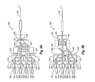
- FIGS. 3A , 3 B, 3 C, and 3 D are schematic views of third, fourth, fifth, and sixth example multi-laser TOSAs, respectively;
- FIGS. 4A , 4 B, and 4 C is a schematic view of seventh, eighth, and ninth example multi-laser TOSAs, respectively.
- FIG. 5 is a schematic view of a tenth example multi-laser TOSA.
- Example embodiments of the present invention relate to multi-laser transmitter optical subassemblies (TOSAs) for optoelectronic modules.
- TOSAs multi-laser transmitter optical subassemblies
- At least some example multi-laser TOSAs disclosed herein exhibit a relatively low size, cost, and optical loss, thus enabling relatively improved overall performance of the optoelectronic modules into which the TOSAs are integrated.
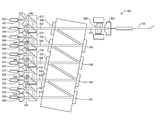
- FIG. 1 discloses an example optoelectronic module 100 for use in transmitting and receiving optical signals in connection with a host device (not shown).
- the module 100 is one environment in which example embodiments of the invention can be practiced.
- the module 100 includes various components, including a bottom housing 102 configured to mate with a top housing (not shown), a receive port 104 and a transmit port 106 defined in the bottom housing 102 , a printed circuit board (PCB) 108 positioned within the bottom housing 102 , a receiver optical subassembly (ROSA) 110 , and a TOSA 112 .
- An edge connector 114 is located on an end of the PCB 108 to enable the module 100 to electrically interface with a host device (not shown). As such, the PCB 108 facilitates electrical communication between the ROSA 110 /TOSA 112 and the host device.
- the module 100 can be configured for optical signal transmission and reception at a variety of data rates including, but not limited to, 40 Gb/s, 100 Gb/s, or higher. Furthermore, the module 100 can be configured for optical signal transmission and reception at various distinct wavelengths using wavelength division multiplexing (WDM) in which multiple optical signals having distinct wavelengths are multiplexed onto a single optical fiber. For example, the module 100 can be configured to operate using one of various WDM schemes, such as Coarse WDM (CWDM), Dense WDM (DWDM), or Light WDM (LWDM). Further, the module 100 can be configured to support various communication protocols including, but not limited to, Fibre Channel and High Speed Ethernet.
- WDM wavelength division multiplexing
- CWDM Coarse WDM
- DWDM Dense WDM
- LWDM Light WDM
- the module 100 can be configured to support various communication protocols including, but not limited to, Fibre Channel and High Speed Ethernet.
- example module 100 is configured to have a form factor that is substantially compliant with the QSFP MSA
- the module 100 can alternatively be configured in a variety of different form factors that are substantially compliant with other MSAs including, but not limited to, the CFP MSA.
- the ROSA 110 houses an optical receiver such as a photodiode (not shown) that is electrically coupled to an electrical interface 116 .
- the TOSA 112 houses multiple optical transmitters such as lasers (not shown) that are electrically coupled to the other electrical interface 118 .
- the optical receiver is configured to convert optical signals received through the receive port 104 into corresponding electrical signals that are relayed to the PCB 108 .
- the optical transmitter is configured to convert electrical signals received through the PCB 108 from a host device (not shown) into corresponding optical signals that are transmitted through the transmit port 106 .
- the ROSA 110 serves as an optical-electronic transducer and the TOSA 112 serves as an electronic-optical transducer.
- the optical ports 104 and 106 are configured to optically connect the optical receiver and the optical transceiver, respectively, with optical fibers and corresponding optical fiber connectors such as LC or SC connectors (not shown) that are connected to the optical ports.
- the TOSA 200 can be employed in a WDM environment in order to increase the data throughput on a single optical fiber 120 .
- the TOSA 200 includes first and second lasers 202 and 204 configured to generate first and second optical signals 206 and 208 , respectively.
- the first and second lasers 202 and 204 may be distributed feedback lasers (DFBs), for example.
- the first optical signal 206 may have a first distinct wavelength and the second optical signal 208 may have a second distinct wavelength. It is understood, however, that the first and second optical signals 206 and 208 may alternatively have the same wavelength.
- the TOSA 200 also includes a polarization beam combiner (PBC) 210 , a half waveplate 212 positioned between the first laser 202 and the PBC 210 , and a focusing lens 214 .
- PBC polarization beam combiner
- the half waveplate 212 is configured to rotate the polarization of the first optical signal 206 to be substantially orthogonal to the polarization of the second optical signal 208 .
- the PBC 210 is then configured to combine the first and second optical signals 206 and 208 and transmit the combined first and second optical signals 216 through the focusing lens 214 and into the optical fiber 120 .
- the TOSA 200 may also include first and second collimating lenses 218 and 220 positioned between the first and second lasers 202 and 204 , respectively, and the PBC 210 .
- the TOSA 200 may also include an isolator 222 positioned between the PBC 210 and the focusing lens 214 to reduce or prevent back reflection from reaching either of the lasers 202 or 204 . Since the first and second optical signals 206 and 208 in the combined optical signal 216 do not have the same linear polarization state, the isolator 222 may be a polarization insensitive isolator.
- the TOSA 200 ′ can be employed in a WDM environment in order to increase the data throughput on the optical fiber 120 .
- the TOSA 200 ′ is identical to the TOSA 200 of FIG. 2A , except that the isolator 222 is replaced with an isolator 224 .
- the isolator 224 is a polarizer garnet polarizer (PGP) isolator.
- PGP garnet polarizer
- the first polarizer (P) of the PGP isolator is configured such that the polarization axis is about 45 degrees off of the horizontal or vertical plane resulting in each channel having an inherently balanced about 3 dB loss.
- the isolator 224 is generally less expensive than the isolator 222 , the isolator 222 generally exhibits lower levels of optical loss.
- the TOSA 300 can be employed in a WDM environment in order to increase the data throughput on the optical fiber 120 .
- the TOSA 300 includes first, second, third, and fourth lasers 302 - 308 configured to generate first, second, third, and fourth optical signals 310 - 316 , respectively.
- the optical signals 310 - 316 may have first, second, third, and fourth distinct wavelengths, respectively. Alternatively, one or more of the optical signals 310 - 316 may have the same wavelength.
- the TOSA 300 also includes first and second PBCs 318 and 320 , first and second half waveplate 322 and 324 , and a focusing lens 326 .
- the first half waveplate 322 is positioned between the first laser 302 and the PBC 318 .
- the second half waveplate 324 is positioned between the fourth laser 308 and the PBC 320 .
- the half waveplates 322 and 324 are configured to rotate the polarizations of the first and fourth optical signals 310 and 316 to be substantially orthogonal to the polarizations of the second and third optical signals 312 and 314 .
- the PBC 318 is then configured to combine the first and second optical signals 310 and 312 and transmit the combined first and second optical signals 328 toward the focusing lens 326 .
- the PBC 320 is then configured to combine the third and fourth optical signals 314 and 316 and transmit the combined third and fourth optical signals 330 toward the focusing lens 326 .
- the TOSA 300 may also include first and second collimating lenses 332 and 334 positioned between the lasers 302 and 304 , respectively, and the PBC 318 , as well as third and fourth collimating lenses 336 and 338 positioned between the lasers 306 and 308 , respectively, and the PBC 320 .
- the TOSA 300 may also include an isolator 340 positioned between the PBCs 318 and 320 and the focusing lens 326 to reduce or prevent back reflection from reaching any of the lasers 302 - 308 .
- the isolator 340 is a PGP isolator.
- the TOSA 300 may also include a third PBC 342 positioned between the isolator 340 and the focusing lens 326 , as well as a third half waveplate 344 positioned between the isolator 340 and the third PBC 342 .
- the third half waveplate 344 is configured to rotate the polarization of the combined third and fourth optical signals 330
- the third PBC 342 is configured to combine the combined first and second optical signals 328 and the combined third and fourth optical signals 330 and transmit the combined first, second, third, and fourth optical signals 346 through the focusing lens 326 and into the optical fiber 120 .
- the TOSA 300 ′ can be employed in a WDM environment in order to increase the data throughput on the optical fiber 120 .
- the TOSA 300 ′ is identical to the TOSA 300 of FIG. 3A , except that the third PBC 342 is omitted, a minor 348 and a filter 350 are added, and the isolator 340 is replaced with an isolator 352 .
- the isolator 352 is a polarization insensitive isolator.
- the optical signals 310 - 316 of the TOSA 300 ′ of FIG. 3B may have first, second, third, and fourth distinct wavelengths, respectively, or, alternatively, the optical signals 310 and 312 may have a first distinct wavelength and the optical signals 314 and 316 may have a second distinct wavelength.
- the mirror 348 is configured to reflect the combined third and fourth optical signals 330 toward the filter 350
- the filter 350 is configured to both transmit the combined first and second optical signals 328 and reflect the combined third and fourth optical signal 330 such that the combined first, second, third, and fourth optical signals 346 can pass through the isolator 352 , through the focusing lens 326 , and into the optical fiber 120 .
- the TOSA 300 ′′ can be employed in a WDM environment in order to increase the data throughput on the optical fiber 120 .
- the TOSA 300 ′′ is identical to the TOSA 300 of FIG. 3A , except that the isolator 340 and the half waveplate 344 are removed and an optical component 354 is added.
- the optical component 354 can be a polarizer with an about 45 degree polarization axis.
- the optical component 354 can be a half waveplate with an optical axis that is oriented about 22.5 degrees or about 67.5 degrees relative to the horizontal or vertical plane.
- the TOSA 300 ′′' can be employed in a WDM environment in order to increase the data throughput on the optical fiber 120 .
- the TOSA 300 ′′' is identical to the TOSA 300 ′′ of FIG. 3C , except that the isolator 352 has been added between the third PBC 342 and the focusing lens 326 .
- the TOSA 400 can be employed in a WDM environment in order to increase the data throughput on the optical fiber 120 .
- the TOSA 400 includes first, second, third, and fourth lasers 402 - 408 configured to generate first, second, third, and fourth optical signals 410 - 416 , respectively.
- the optical signals 410 - 416 may have first, second, third, and fourth distinct wavelengths, respectively. Alternatively, one or more of the optical signals 410 - 416 may have the same wavelength.
- the TOSA 400 also includes first and second PBCs 418 and 420 , first and second half waveplates 422 and 424 , and a focusing lens 426 .
- the first half waveplate 422 is positioned between the first and second lasers 402 and 404 and the PBC 418 .
- the second half waveplate 424 is positioned between the first and second PBCs 418 and 420 .
- the half waveplate 422 is configured to rotate the polarizations of the first and second optical signals 410 and 412 to be substantially orthogonal to the polarizations of the third and fourth optical signals 414 and 416 .
- the PBC 418 is then configured to combine the first and third optical signals 410 and 414 and transmit the combined first and third optical signals 428 toward the second PBC 420 .
- the PBC 418 is also configured to combine the second and fourth optical signals 412 and 416 and transmit the combined second and fourth optical signals 430 toward the second PBC 420 .
- the half waveplate 424 is next configured to rotate the polarizations of the combined second and fourth optical signals 430 .
- the PBC 420 is then configured to combine the combined first and third optical signals 428 and the combined second and fourth optical signal 430 and transmit the combined first, second, third, and fourth optical signals 432 through the focusing lens 426 and into an optical fiber 120 .
- the TOSA 400 may also include first, second, third, and fourth collimating lenses 434 - 440 positioned between the lasers 402 - 408 , respectively, and the PBC 418 .
- the TOSA 400 may also include an isolator 442 positioned between the PBCs 418 and 420 and the focusing lens 426 to reduce or prevent back reflection from reaching any of the lasers 402 - 408 .
- the isolator 442 is a PGP isolator.
- the TOSA 400 ′ can be employed in a WDM environment in order to increase the data throughput on the optical fiber 120 .
- the TOSA 400 ′ is identical to the TOSA 400 of FIG. 4A , except that the isolator 442 and the half waveplate 424 are removed and an optical component 444 is added.
- the optical component 444 can be a polarizer with an about 45 degree polarization axis.
- the optical component 444 can be a half waveplate with an optical axis that is oriented about 22.5 degrees or about 67.5 degrees relative to the horizontal or vertical plane.
- the TOSA 400 ′′ can be employed in a WDM environment in order to increase the data throughput on the optical fiber 120 .
- the TOSA 400 ′′ is identical to the TOSA 400 ′ of FIG. 3C , except that an isolator 446 has been added between the second PBC 420 and the focusing lens 426 .
- the isolator 446 is a polarization insensitive isolator.
- the TOSA 500 can be employed in a WDM environment in order to increase the data throughput on the optical fiber 120 .
- the TOSA 500 also includes N lasers 502 - 520 configured to generate N optical signals 522 - 540 , respectively.
- the TOSA 500 also includes N collimating lenses 542 - 560 , N/2 half waveplates 562 - 570 , N/2 PBCs 572 - 580 , (N ⁇ 1)/2 minors 582 - 588 , (N ⁇ 1)/2 filters 590 - 596 , an isolator 598 , and a focusing lens 600 .
- the N optical signals 522 - 540 may have N distinct wavelengths, respectively.
- any two of the N optical signals 522 - 540 that share the same PBC may have the same wavelength.
- optical signals 522 and 524 may have a first distinct wavelength
- optical signals 526 and 528 may have a second distinct wavelength
- optical signal 530 and 532 may have a third distinct wavelength, and so forth.
- the half waveplates 562 - 570 are positioned between the odd-positioned additional lasers (namely, the first lasers 502 , the third laser 506 , the fifth laser 510 , the seventh laser 514 , and the ninth laser 518 ) and the PBCs 572 - 80 , respectively. Since the lasers 502 - 520 generally have a fixed polarization, during operation of the TOSA 500 the half waveplates 562 - 570 are configured to rotate the polarizations of the optical signals 522 , 526 , 530 , 534 , and 538 to be substantially orthogonal to the polarizations of the optical signals 524 , 528 , 532 , 536 , and 540 , respectively.
- the PBCs 572 - 580 are then configured to combine the optical signals 522 and 524 , 526 and 528 , 530 and 532 , 534 and 536 , and 538 and 540 , respectively.
- the mirrors 582 - 588 and the filters 590 - 596 then cooperate to combine the combined optical signals 602 - 610 into a combined optical signal 612 that includes all of the optical signals 522 - 540 .
- the combined optical signal 612 then passed through the isolator 598 , which is a polarization insensitive isolator, through the focusing lens 600 , and into the optical fiber 120 .
- the number N of lasers in the tenth example multi-laser TOSA 500 is equal to ten, it is understood that the TOSA 500 could be modified to have less than ten lasers or greater than ten lasers. Further, the relative numbers of collimating lenses, half waveplates, PBCs, mirrors, and filters are generally accurate where N is an even integer that is greater than or equal to two. It is understood, however, that the TOSA 500 may alternatively include an odd number of lasers.
- each of the example multi-laser TOSAs disclosed herein enables the combination of multiple optical signals with relatively low optical loss.
- the size and cost of the example multi-laser TOSAs disclosed herein are also relatively low compared to prior art multi-laser TOSAs.
- One reason for the relatively low size and cost of the example multi-laser TOSAs disclosed herein is that fewer and generally less expensive components are used in the example multi-laser TOSAs disclosed herein. For example, many prior art multi-laser TOSAs require N ⁇ 1 filters and N ⁇ 1 minors, where N is the number of lasers in the TOSA.
- the use of the PBCs completely eliminates the need for filters and minors in the example multi-laser TOSAs 200 , 200 ′, 300 , 300 ′′, 300 ′′′, 400 , 400 ′, and 400 ′′ and reduces the need by half for filters and minors in the example multi-laser TOSAs 300 ′ and 500 .
Abstract
Description
- Optoelectronic modules, such as optoelectronic transceiver or transponder modules, are increasingly used in electronic and optoelectronic communication. Some modules can be plugged into a variety of host networking equipment. Modules typically communicate with a printed circuit board of a host device by transmitting electrical signals to the printed circuit board and receiving electrical signals from the printed circuit board. These electrical signals can then be transmitted by the module outside the host device as optical signals.
- Multi-source agreements (MSAs), such as the C Form-factor Pluggable (CFP) MSA and the Quad Small Form-factor Pluggable (QSFP) MSA, specify, among other things, housing dimensions for modules. Conformity with an MSA allows a module to be plugged into host equipment designed in compliance with the MSA.
- Optical signals are typically generated within a transmitter optical subassembly (TOSA) of a module using a laser, such as a vertical cavity surface emitting laser (VCSEL) or a distributed feedback (DFB) laser. As data rates in modules increase, two or more lasers are often included in a single TOSA. However, as MSAs specify increasingly smaller module housing dimensions, there is less available space for multi-laser TOSAs within the module housing. In addition, multi-laser TOSAs are often relatively expensive and often suffer from relatively high optical loss.
- In general, example embodiments of the invention relate to multi-laser transmitter optical subassemblies (TOSAs) for optoelectronic modules. At least some example multi-laser TOSAs disclosed herein exhibit a relatively low size, cost, and optical loss, thus enabling relatively improved overall performance of the optoelectronic modules into which the TOSAs are integrated.
- In one example embodiment, a multi-laser TOSA includes first and second lasers configured to generate first and second optical signals, respectively, a polarization beam combiner (PBC), first and second collimating lenses positioned between the first and second lasers, respectively, and the PBC, a half waveplate positioned between the first laser and the PBC, and a focusing lens. The half waveplate is configured to rotate the polarization of the first optical signal. The PBC is configured to combine the first and second optical signals and transmit the combined first and second optical signals toward the focusing lens.
- In another example embodiment, an optoelectronic transceiver module includes a printed circuit board, a receiver optical subassembly (ROSA) in electrical communication with the printed circuit board, and a multi-laser TOSA in electrical communication with the printed circuit board. The multi-laser TOSA includes first and second lasers configured to generate first and second optical signals, respectively, a PBC, first and second collimating lenses positioned between the first and second lasers, respectively, and the PBC, a half waveplate positioned between the first laser and the PBC, and a focusing lens. The half waveplate is configured to rotate the polarization of the first optical signal. The PBC is configured to combine the first and second optical signals and transmit the combined first and second optical signals through the isolator toward the focusing lens.
- In yet another example embodiment, a multi-laser TOSA includes first, second, third, and fourth lasers configured to generate first, second, third, and fourth optical signals, respectively, a first PBC, first, second, third, and fourth collimating lenses positioned between the first, second, third, and fourth lasers, respectively, and the first PBC, a first half waveplate positioned between the first and second collimating lenses and the first PBC, a focusing lens, and a second PBC positioned between the first PBC and the focusing lens. The first half waveplate is configured to rotate the polarization of the first and second optical signals. The first PBC is configured to combine the first and third optical signals. The first PBC is also configured to combine the second and fourth optical signals. The second half waveplate is configured to rotate the polarization of the combined second and fourth optical signals. The second PBC is configured to combine the combined first and third optical signals and the combined second and fourth optical signals and transmit the combined first, second, third, and fourth optical signals toward the focusing lens.
- This Summary is provided to introduce a selection of concepts in a simplified form that are further described below in the Detailed Description. This Summary is not intended to identify key features or essential characteristics of the claimed subject matter, nor is it intended to be used as an aid in determining the scope of the claimed subject matter.
- Additional features will be set forth in the description which follows, and in part will be obvious from the description, or may be learned by the practice of the teachings herein. Features of the invention may be realized and obtained by means of the instruments and combinations particularly pointed out in the appended claims. Features of the present invention will become more fully apparent from the following description and appended claims, or may be learned by the practice of the invention as set forth hereinafter.
- To further clarify certain aspects of the present invention, a more particular description of the invention will be rendered by reference to example embodiments thereof which are disclosed in the appended drawings. It is appreciated that these drawings depict only example embodiments of the invention and are therefore not to be considered limiting of its scope. Aspects of the invention will be described and explained with additional specificity and detail through the use of the accompanying drawings in which:
-
FIG. 1 is a perspective view of an example optoelectronic module and associated transmitter optical subassembly (TOSA); -
FIGS. 2A and 2B are schematic views of first and second example multi-laser TOSAs, respectively; -
FIGS. 3A , 3B, 3C, and 3D are schematic views of third, fourth, fifth, and sixth example multi-laser TOSAs, respectively; -
FIGS. 4A , 4B, and 4C is a schematic view of seventh, eighth, and ninth example multi-laser TOSAs, respectively; and -
FIG. 5 is a schematic view of a tenth example multi-laser TOSA. - Example embodiments of the present invention relate to multi-laser transmitter optical subassemblies (TOSAs) for optoelectronic modules. At least some example multi-laser TOSAs disclosed herein exhibit a relatively low size, cost, and optical loss, thus enabling relatively improved overall performance of the optoelectronic modules into which the TOSAs are integrated.
- Reference will now be made to the drawings to describe various aspects of example embodiments of the invention. It is to be understood that the drawings are diagrammatic and schematic representations of such example embodiments, and are not limiting of the present invention, nor are they necessarily drawn to scale.
- Reference is first made to
FIG. 1 which discloses an exampleoptoelectronic module 100 for use in transmitting and receiving optical signals in connection with a host device (not shown). Themodule 100 is one environment in which example embodiments of the invention can be practiced. As disclosed inFIG. 1 , themodule 100 includes various components, including abottom housing 102 configured to mate with a top housing (not shown), areceive port 104 and atransmit port 106 defined in thebottom housing 102, a printed circuit board (PCB) 108 positioned within thebottom housing 102, a receiver optical subassembly (ROSA) 110, and a TOSA 112. Anedge connector 114 is located on an end of thePCB 108 to enable themodule 100 to electrically interface with a host device (not shown). As such, the PCB 108 facilitates electrical communication between the ROSA 110/TOSA 112 and the host device. - The
module 100 can be configured for optical signal transmission and reception at a variety of data rates including, but not limited to, 40 Gb/s, 100 Gb/s, or higher. Furthermore, themodule 100 can be configured for optical signal transmission and reception at various distinct wavelengths using wavelength division multiplexing (WDM) in which multiple optical signals having distinct wavelengths are multiplexed onto a single optical fiber. For example, themodule 100 can be configured to operate using one of various WDM schemes, such as Coarse WDM (CWDM), Dense WDM (DWDM), or Light WDM (LWDM). Further, themodule 100 can be configured to support various communication protocols including, but not limited to, Fibre Channel and High Speed Ethernet. In addition, although theexample module 100 is configured to have a form factor that is substantially compliant with the QSFP MSA, themodule 100 can alternatively be configured in a variety of different form factors that are substantially compliant with other MSAs including, but not limited to, the CFP MSA. - With continued reference to
FIG. 1 , the ROSA 110 houses an optical receiver such as a photodiode (not shown) that is electrically coupled to anelectrical interface 116. The TOSA 112 houses multiple optical transmitters such as lasers (not shown) that are electrically coupled to the otherelectrical interface 118. The optical receiver is configured to convert optical signals received through thereceive port 104 into corresponding electrical signals that are relayed to thePCB 108. The optical transmitter is configured to convert electrical signals received through thePCB 108 from a host device (not shown) into corresponding optical signals that are transmitted through thetransmit port 106. Accordingly, theROSA 110 serves as an optical-electronic transducer and theTOSA 112 serves as an electronic-optical transducer. Theoptical ports - Having described a specific environment with respect to
FIG. 1 , it will be understood that this specific environment is only one of countless architectures in which example embodiments of the present invention may be employed. The scope of the present invention is not intended to be limited to any particular environment. - With reference now to
FIG. 2A , aspects of a firstexample multi-laser TOSA 200 are disclosed. TheTOSA 200 can be employed in a WDM environment in order to increase the data throughput on a singleoptical fiber 120. - As disclosed in
FIG. 2A , theTOSA 200 includes first andsecond lasers optical signals second lasers optical signal 206 may have a first distinct wavelength and the secondoptical signal 208 may have a second distinct wavelength. It is understood, however, that the first and secondoptical signals TOSA 200 also includes a polarization beam combiner (PBC) 210, ahalf waveplate 212 positioned between thefirst laser 202 and thePBC 210, and a focusinglens 214. - Since the first and
second lasers TOSA 200 thehalf waveplate 212 is configured to rotate the polarization of the firstoptical signal 206 to be substantially orthogonal to the polarization of the secondoptical signal 208. ThePBC 210 is then configured to combine the first and secondoptical signals optical signals 216 through the focusinglens 214 and into theoptical fiber 120. - As disclosed in
FIG. 2A , theTOSA 200 may also include first and secondcollimating lenses second lasers PBC 210. TheTOSA 200 may also include anisolator 222 positioned between thePBC 210 and the focusinglens 214 to reduce or prevent back reflection from reaching either of thelasers optical signals optical signal 216 do not have the same linear polarization state, theisolator 222 may be a polarization insensitive isolator. - With reference now to
FIG. 2B , aspects of a secondexample multi-laser TOSA 200′ are disclosed. TheTOSA 200′ can be employed in a WDM environment in order to increase the data throughput on theoptical fiber 120. - As disclosed in
FIG. 2B , theTOSA 200′ is identical to theTOSA 200 ofFIG. 2A , except that theisolator 222 is replaced with anisolator 224. Theisolator 224 is a polarizer garnet polarizer (PGP) isolator. In at least some example embodiments, the first polarizer (P) of the PGP isolator is configured such that the polarization axis is about 45 degrees off of the horizontal or vertical plane resulting in each channel having an inherently balanced about 3 dB loss. Although theisolator 224 is generally less expensive than theisolator 222, theisolator 222 generally exhibits lower levels of optical loss. - With reference now to
FIG. 3A , aspects of a thirdexample multi-laser TOSA 300 are disclosed. TheTOSA 300 can be employed in a WDM environment in order to increase the data throughput on theoptical fiber 120. - As disclosed in
FIG. 3A , theTOSA 300 includes first, second, third, and fourth lasers 302-308 configured to generate first, second, third, and fourth optical signals 310-316, respectively. The optical signals 310-316 may have first, second, third, and fourth distinct wavelengths, respectively. Alternatively, one or more of the optical signals 310-316 may have the same wavelength. TheTOSA 300 also includes first and second PBCs 318 and 320, first andsecond half waveplate lens 326. Thefirst half waveplate 322 is positioned between thefirst laser 302 and thePBC 318. Thesecond half waveplate 324 is positioned between thefourth laser 308 and thePBC 320. - As the lasers 302-308 generally have a fixed polarization, during operation of the
TOSA 300 the half waveplates 322 and 324 are configured to rotate the polarizations of the first and fourthoptical signals optical signals PBC 318 is then configured to combine the first and secondoptical signals optical signals 328 toward the focusinglens 326. Simultaneously, thePBC 320 is then configured to combine the third and fourthoptical signals optical signals 330 toward the focusinglens 326. - As disclosed in
FIG. 3A , theTOSA 300 may also include first and secondcollimating lenses lasers PBC 318, as well as third and fourthcollimating lenses lasers PBC 320. TheTOSA 300 may also include an isolator 340 positioned between thePBCs lens 326 to reduce or prevent back reflection from reaching any of the lasers 302-308. The isolator 340 is a PGP isolator. - As disclosed in
FIG. 3A , theTOSA 300 may also include a third PBC 342 positioned between the isolator 340 and the focusinglens 326, as well as athird half waveplate 344 positioned between the isolator 340 and the third PBC 342. During operation of theTOSA 300, thethird half waveplate 344 is configured to rotate the polarization of the combined third and fourthoptical signals 330, and the third PBC 342 is configured to combine the combined first and secondoptical signals 328 and the combined third and fourthoptical signals 330 and transmit the combined first, second, third, and fourthoptical signals 346 through the focusinglens 326 and into theoptical fiber 120. - With reference now to
FIG. 3B , aspects of a fourthexample multi-laser TOSA 300′ are disclosed. TheTOSA 300′ can be employed in a WDM environment in order to increase the data throughput on theoptical fiber 120. - As disclosed in
FIG. 3B , theTOSA 300′ is identical to theTOSA 300 ofFIG. 3A , except that the third PBC 342 is omitted, a minor 348 and a filter 350 are added, and the isolator 340 is replaced with anisolator 352. Theisolator 352 is a polarization insensitive isolator. In addition, another difference from theTOSA 300 ofFIG. 3A is that the optical signals 310-316 of theTOSA 300′ ofFIG. 3B may have first, second, third, and fourth distinct wavelengths, respectively, or, alternatively, theoptical signals optical signals - During operation of the
TOSA 300′, themirror 348 is configured to reflect the combined third and fourthoptical signals 330 toward the filter 350, the filter 350 is configured to both transmit the combined first and secondoptical signals 328 and reflect the combined third and fourthoptical signal 330 such that the combined first, second, third, and fourthoptical signals 346 can pass through theisolator 352, through the focusinglens 326, and into theoptical fiber 120. - With reference now to
FIG. 3C , aspects of a fifthexample multi-laser TOSA 300″ are disclosed. TheTOSA 300″ can be employed in a WDM environment in order to increase the data throughput on theoptical fiber 120. - As disclosed in
FIG. 3C , theTOSA 300″ is identical to theTOSA 300 ofFIG. 3A , except that the isolator 340 and thehalf waveplate 344 are removed and anoptical component 354 is added. Theoptical component 354 can be a polarizer with an about 45 degree polarization axis. Alternatively, theoptical component 354 can be a half waveplate with an optical axis that is oriented about 22.5 degrees or about 67.5 degrees relative to the horizontal or vertical plane. - With reference now to
FIG. 3D , aspects of a sixthexample multi-laser TOSA 300″' are disclosed. TheTOSA 300″' can be employed in a WDM environment in order to increase the data throughput on theoptical fiber 120. - As disclosed in
FIG. 3D , theTOSA 300″' is identical to theTOSA 300″ ofFIG. 3C , except that theisolator 352 has been added between the third PBC 342 and the focusinglens 326. - With reference now to
FIG. 4A , aspects of a seventhexample multi-laser TOSA 400 are disclosed. TheTOSA 400 can be employed in a WDM environment in order to increase the data throughput on theoptical fiber 120. - As disclosed in
FIG. 4A , theTOSA 400 includes first, second, third, and fourth lasers 402-408 configured to generate first, second, third, and fourth optical signals 410-416, respectively. The optical signals 410-416 may have first, second, third, and fourth distinct wavelengths, respectively. Alternatively, one or more of the optical signals 410-416 may have the same wavelength. TheTOSA 400 also includes first and second PBCs 418 and 420, first and second half waveplates 422 and 424, and a focusinglens 426. Thefirst half waveplate 422 is positioned between the first andsecond lasers PBC 418. Thesecond half waveplate 424 is positioned between the first and second PBCs 418 and 420. - As the lasers 402-408 generally have a fixed polarization, during operation of the
TOSA 400 thehalf waveplate 422 is configured to rotate the polarizations of the first and secondoptical signals optical signals PBC 418 is then configured to combine the first and thirdoptical signals optical signals 428 toward thesecond PBC 420. Simultaneously, thePBC 418 is also configured to combine the second and fourthoptical signals optical signals 430 toward thesecond PBC 420. Thehalf waveplate 424 is next configured to rotate the polarizations of the combined second and fourth optical signals 430. ThePBC 420 is then configured to combine the combined first and thirdoptical signals 428 and the combined second and fourthoptical signal 430 and transmit the combined first, second, third, and fourthoptical signals 432 through the focusinglens 426 and into anoptical fiber 120. - As disclosed in
FIG. 4A , theTOSA 400 may also include first, second, third, and fourth collimating lenses 434-440 positioned between the lasers 402-408, respectively, and thePBC 418. TheTOSA 400 may also include anisolator 442 positioned between thePBCs lens 426 to reduce or prevent back reflection from reaching any of the lasers 402-408. Theisolator 442 is a PGP isolator. - With reference now to
FIG. 4B , aspects of an eighthexample multi-laser TOSA 400′ are disclosed. TheTOSA 400′ can be employed in a WDM environment in order to increase the data throughput on theoptical fiber 120. - As disclosed in
FIG. 4B , theTOSA 400′ is identical to theTOSA 400 ofFIG. 4A , except that theisolator 442 and thehalf waveplate 424 are removed and anoptical component 444 is added. Theoptical component 444 can be a polarizer with an about 45 degree polarization axis. Alternatively, theoptical component 444 can be a half waveplate with an optical axis that is oriented about 22.5 degrees or about 67.5 degrees relative to the horizontal or vertical plane. - 10. Ninth Example Multi-Laser TOSA
- With reference now to
FIG. 4C , aspects of a ninthexample multi-laser TOSA 400″ are disclosed. TheTOSA 400″ can be employed in a WDM environment in order to increase the data throughput on theoptical fiber 120. - As disclosed in
FIG. 4C , theTOSA 400″ is identical to theTOSA 400′ ofFIG. 3C , except that anisolator 446 has been added between thesecond PBC 420 and the focusinglens 426. Theisolator 446 is a polarization insensitive isolator. - With reference now to
FIG. 5 , aspects of a tenthexample multi-laser TOSA 500 are disclosed. TheTOSA 500 can be employed in a WDM environment in order to increase the data throughput on theoptical fiber 120. - As disclosed in
FIG. 5 , theTOSA 500 also includes N lasers 502-520 configured to generate N optical signals 522-540, respectively. TheTOSA 500 also includes N collimating lenses 542-560, N/2 half waveplates 562-570, N/2 PBCs 572-580, (N−1)/2 minors 582-588, (N−1)/2 filters 590-596, anisolator 598, and a focusinglens 600. The N optical signals 522-540 may have N distinct wavelengths, respectively. Alternatively, any two of the N optical signals 522-540 that share the same PBC may have the same wavelength. For example,optical signals optical signals optical signal - The half waveplates 562-570 are positioned between the odd-positioned additional lasers (namely, the
first lasers 502, thethird laser 506, thefifth laser 510, theseventh laser 514, and the ninth laser 518) and the PBCs 572-80, respectively. Since the lasers 502-520 generally have a fixed polarization, during operation of theTOSA 500 the half waveplates 562-570 are configured to rotate the polarizations of theoptical signals optical signals optical signals optical signal 612 that includes all of the optical signals 522-540. The combinedoptical signal 612 then passed through theisolator 598, which is a polarization insensitive isolator, through the focusinglens 600, and into theoptical fiber 120. - Although the number N of lasers in the tenth
example multi-laser TOSA 500 is equal to ten, it is understood that theTOSA 500 could be modified to have less than ten lasers or greater than ten lasers. Further, the relative numbers of collimating lenses, half waveplates, PBCs, mirrors, and filters are generally accurate where N is an even integer that is greater than or equal to two. It is understood, however, that theTOSA 500 may alternatively include an odd number of lasers. - The use of PBCs in each of the example multi-laser TOSAs disclosed herein enables the combination of multiple optical signals with relatively low optical loss. The size and cost of the example multi-laser TOSAs disclosed herein are also relatively low compared to prior art multi-laser TOSAs. One reason for the relatively low size and cost of the example multi-laser TOSAs disclosed herein is that fewer and generally less expensive components are used in the example multi-laser TOSAs disclosed herein. For example, many prior art multi-laser TOSAs require N−1 filters and N−1 minors, where N is the number of lasers in the TOSA. However, in the example multi-laser TOSAs disclosed herein, the use of the PBCs completely eliminates the need for filters and minors in the
example multi-laser TOSAs example multi-laser TOSAs 300′ and 500. - The use of PBCs in each of the example multi-laser TOSAs disclosed herein thus enables the example multi-laser TOSAs disclosed herein to exhibit a relatively low size, cost, and optical loss. Consequently, optoelectronic modules into which the TOSAs are integrated also exhibit relatively improved overall performance.
- The example embodiments disclosed herein may be embodied in other specific forms. The example embodiments disclosed herein are to be considered in all respects only as illustrative and not restrictive.
Claims (20)
Priority Applications (5)
| Application Number | Priority Date | Filing Date | Title |
|---|---|---|---|
| US13/011,770 US8625989B2 (en) | 2011-01-21 | 2011-01-21 | Multi-laser transmitter optical subassemblies for optoelectronic modules |
| EP12736177.2A EP2666045A4 (en) | 2011-01-21 | 2012-01-20 | Multi-laser transmitter optical subassemblies for optoelectronic modules |
| JP2013550639A JP5723028B2 (en) | 2011-01-21 | 2012-01-20 | Multi-laser transmitter optical subassembly and photoelectric transceiver module |
| PCT/US2012/022095 WO2012100209A2 (en) | 2011-01-21 | 2012-01-20 | Multi-laser transmitter optical subassemblies for optoelectronic modules |
| CN201280003497.1A CN103261935B (en) | 2011-01-21 | 2012-01-20 | Multi-laser transmitter optical subassemblies for optoelectronic modules |
Applications Claiming Priority (1)
| Application Number | Priority Date | Filing Date | Title |
|---|---|---|---|
| US13/011,770 US8625989B2 (en) | 2011-01-21 | 2011-01-21 | Multi-laser transmitter optical subassemblies for optoelectronic modules |
Publications (2)
| Publication Number | Publication Date |
|---|---|
| US20120189306A1 true US20120189306A1 (en) | 2012-07-26 |
| US8625989B2 US8625989B2 (en) | 2014-01-07 |
Family
ID=46516414
Family Applications (1)
| Application Number | Title | Priority Date | Filing Date |
|---|---|---|---|
| US13/011,770 Active 2032-02-01 US8625989B2 (en) | 2011-01-21 | 2011-01-21 | Multi-laser transmitter optical subassemblies for optoelectronic modules |
Country Status (5)
| Country | Link |
|---|---|
| US (1) | US8625989B2 (en) |
| EP (1) | EP2666045A4 (en) |
| JP (1) | JP5723028B2 (en) |
| CN (1) | CN103261935B (en) |
| WO (1) | WO2012100209A2 (en) |
Cited By (31)
| Publication number | Priority date | Publication date | Assignee | Title |
|---|---|---|---|---|
| US20120257902A1 (en) * | 2011-04-06 | 2012-10-11 | Futurewei Technologies, Inc. | Device and Method for Optical Beam Combination |
| WO2014030566A1 (en) * | 2012-08-23 | 2014-02-27 | 株式会社村田製作所 | Receptacle and optical transmission module |
| CN103765271A (en) * | 2013-07-29 | 2014-04-30 | 索尔思光电(成都)有限公司 | Multi-path optical transceiver and method for correcting elements thereof |
| JP2014518402A (en) * | 2011-07-14 | 2014-07-28 | 華為技術有限公司 | Optical signal multiplexing method and optical multiplexing apparatus |
| US20140321856A1 (en) * | 2012-10-26 | 2014-10-30 | Sumitomo Electric Industries, Ltd. | Wavelength multiplexed transmitter optical module |
| US20150037038A1 (en) * | 2013-08-05 | 2015-02-05 | Hitachi Metals, Ltd. | Optical Module |
| JP2015108646A (en) * | 2013-12-03 | 2015-06-11 | 住友電気工業株式会社 | Optical receiver module |
| US20150333833A1 (en) * | 2014-05-13 | 2015-11-19 | Sumitomo Electric Industries, Ltd. | Method to produce optical module having multiple signal lanes and optical module |
| US9215032B2 (en) * | 2013-02-27 | 2015-12-15 | Source Photonics (Chengdu) Company Limited | Multi-channel optical transmitter assembly and methods of making and using the same |
| US20160028489A1 (en) * | 2014-05-13 | 2016-01-28 | Sumitomo Electric Industries, Ltd. | Optical transmitter module having multiple signal lanes |
| US9350454B2 (en) * | 2011-01-21 | 2016-05-24 | Finisar Corporation | Multi-laser transmitter optical subassembly |
| US20160170146A1 (en) * | 2014-12-11 | 2016-06-16 | Sumitomo Electric Industries, Ltd. | Transmitting optical module implementing optical waveguide device |
| US9519151B2 (en) | 2013-12-24 | 2016-12-13 | Huawei Technologies Co., Ltd. | Optical multiplexer and transmitter optical subassembly |
| EP2997405A4 (en) * | 2013-05-14 | 2017-01-18 | Applied Optoelectronics, Inc. | Compact multi-channel optical transceiver module |
| US20170038541A1 (en) * | 2015-08-03 | 2017-02-09 | Sumitomo Electric Industries, Ltd. | Method of producing optical module and optical module |
| US20170048015A1 (en) * | 2015-08-12 | 2017-02-16 | Finisar Corporation | Swdm osas |
| US9628192B2 (en) | 2014-10-30 | 2017-04-18 | Huawei Technologies Co., Ltd. | Optical transmitter, wavelength alignment method, and passive optical network system |
| CN107111079A (en) * | 2014-10-31 | 2017-08-29 | 住友电气工业株式会社 | Luminescence component and multichannel luminescence component |
| EP3063574A4 (en) * | 2013-10-31 | 2017-10-11 | Hewlett-Packard Enterprise Development LP | Multiplexed optoelectronic engines |
| US20170336581A1 (en) * | 2014-10-28 | 2017-11-23 | Sumitomo Electric Industries, Ltd. | Optical module implementing with optical source, optical modulator, and wavelength detector, and a method to assemble the same |
| US9847840B2 (en) | 2013-03-15 | 2017-12-19 | Finisar Corporation | Multi-channel transceiver with laser array and photonic integrated circuit |
| US10018790B1 (en) * | 2017-09-13 | 2018-07-10 | Shimadzu Corporation | Combined-wave (multiplexing) laser beam source |
| WO2019089987A1 (en) * | 2017-11-01 | 2019-05-09 | O-Net Communications (Usa) Inc. | Optical packaging and designs for optical transceivers |
| WO2020029389A1 (en) * | 2018-08-10 | 2020-02-13 | 武汉联特科技有限公司 | Dual light-emitting and dual light-receiving module |
| US10615883B1 (en) * | 2018-10-25 | 2020-04-07 | Elite Advanced Laser Corporation | Wavelength division multiplexing module |
| US10725253B2 (en) * | 2017-12-19 | 2020-07-28 | Lumentum Japan, Inc. | Optical multiplexer/demultiplexer, optical subassembly, and optical module |
| US11054591B2 (en) * | 2019-07-19 | 2021-07-06 | Hangzhou Mo-Link Technology Co. Ltd | Single-fiber bidirectional multimode WDM optical-to-electrical converter and fabrication method thereof |
| KR20220039506A (en) * | 2020-09-21 | 2022-03-29 | 한국전자통신연구원 | Stacked optical communication module and manufacturing method thereof |
| US20220295023A1 (en) * | 2021-03-12 | 2022-09-15 | Osram Opto Semiconductors Gmbh | Optoelectronic light source and data glasses |
| WO2023069618A1 (en) * | 2021-10-20 | 2023-04-27 | Daylight Solutions, Inc. | High power laser assembly with beam combining, multiple levels and fiber coupling |
| US11750293B1 (en) * | 2022-04-21 | 2023-09-05 | Shunyun Technology (Zhong Shan) Limited | Butterfly-type packaged optical transceiver with multiple transmission and reception channels |
Families Citing this family (20)
| Publication number | Priority date | Publication date | Assignee | Title |
|---|---|---|---|---|
| US8995845B2 (en) * | 2012-01-09 | 2015-03-31 | Finisar Corporation | Multi-laser transmitter optical subassembly for optoelectronic modules |
| EP2708926A1 (en) * | 2012-09-13 | 2014-03-19 | u2t Photonics AG | Optical device |
| JP6446955B2 (en) | 2013-10-09 | 2019-01-09 | 住友電気工業株式会社 | Optical transmission module |
| CN104753599B (en) * | 2013-12-30 | 2018-07-13 | 青岛海信宽带多媒体技术有限公司 | A kind of optical module |
| MX362849B (en) * | 2014-02-06 | 2019-02-19 | Nokia Technologies Oy | RECEPTION and GENERATION OF LIGHT. |
| TWM484713U (en) * | 2014-03-10 | 2014-08-21 | Luxnet Corp | Replaceable type light-emitting module and optical transceiver equipped with replaceable type light-emitting module |
| JP6459296B2 (en) * | 2014-08-20 | 2019-01-30 | 住友電気工業株式会社 | Light emitting module and multi-channel light emitting module |
| JP2016134535A (en) * | 2015-01-20 | 2016-07-25 | 住友電気工業株式会社 | Optical module and manufacturing method of the same |
| CN104579537A (en) * | 2014-12-25 | 2015-04-29 | 武汉电信器件有限公司 | CWDM system adopting VCSEL multi-wavelength multiplex structure |
| CN105988222A (en) * | 2015-02-16 | 2016-10-05 | 青岛海信宽带多媒体技术有限公司 | Combiner |
| JP2016197634A (en) * | 2015-04-02 | 2016-11-24 | 日立金属株式会社 | Optical module |
| CN106154444B (en) | 2015-04-28 | 2018-12-28 | 华为技术有限公司 | Optical transceiver and optic communication product |
| CN106405755B (en) * | 2016-11-30 | 2018-11-06 | 武汉光迅科技股份有限公司 | A kind of transceiving device of high-speed multiple channel |
| JP6861062B2 (en) * | 2017-03-22 | 2021-04-21 | 日本ルメンタム株式会社 | Submounts, optical transmission modules, optical modules, optical transmission devices, and their control methods |
| CN107121739B (en) * | 2017-06-23 | 2018-10-30 | 江苏奥雷光电有限公司 | A kind of structure for realizing four road optical transports |
| US11152758B2 (en) * | 2018-09-06 | 2021-10-19 | Nichia Corporation | Light emitting device |
| US10795170B2 (en) | 2018-11-16 | 2020-10-06 | Ii-Vi Delaware Inc. | Multi-channel optical multiplexer or demultiplexer |
| TWI723938B (en) * | 2019-09-12 | 2021-04-01 | 英錡科技股份有限公司 | Laser projecting device and light-combining lens |
| CN111399242A (en) * | 2020-03-27 | 2020-07-10 | 武汉光迅科技股份有限公司 | Four-channel light beam multiplexing system |
| CN112198592B (en) * | 2020-09-03 | 2023-09-05 | 武汉光迅科技股份有限公司 | Optical system |
Citations (10)
| Publication number | Priority date | Publication date | Assignee | Title |
|---|---|---|---|---|
| US4566761A (en) * | 1984-09-13 | 1986-01-28 | Gte Laboratories Incorporated | Birefringent optical wavelength multiplexer/demultiplexer |
| US6134358A (en) * | 1998-08-27 | 2000-10-17 | Chorum Technologies Inc. | N x N switch array with reduced components |
| US6208442B1 (en) * | 1998-03-26 | 2001-03-27 | Chorum Technologies, Inc. | Programmable optical multiplexer |
| US6236480B1 (en) * | 1998-05-01 | 2001-05-22 | Dogan A. Atlas | System and method for reducing Raman cross-talk in a DWDM transport system |
| US6552833B2 (en) * | 1997-04-15 | 2003-04-22 | Macro-Vision Communications, Inc. | Programmable optical add/drop multiplexer |
| US20030133180A1 (en) * | 2001-12-26 | 2003-07-17 | Wuhan Research I.O.P. And Telecom. | Hybrid component and method for combining two pumping lights and depolarizing them simultaneously and optical amplifier therefor |
| US20030194237A1 (en) * | 1999-06-23 | 2003-10-16 | Jds Uniphase Corporation | Micro-optic delay element for use in a time-division multiplexed system |
| US20050254022A1 (en) * | 2004-05-14 | 2005-11-17 | Ki-Hyung Kang | Two-panel type projection system and projection method thereof |
| US20070207670A1 (en) * | 2006-02-13 | 2007-09-06 | Finisar Corporation | Optical transceiver pcb mounting system having emi containment features |
| US20110150477A1 (en) * | 2009-12-18 | 2011-06-23 | Winzer Peter J | Receiver Algorithms for Coherent Detection of Polarization-Multiplexed Optical Signals |
Family Cites Families (11)
| Publication number | Priority date | Publication date | Assignee | Title |
|---|---|---|---|---|
| US6282025B1 (en) | 1999-08-02 | 2001-08-28 | New Focus, Inc. | Optical polarization beam combiner/splitter |
| US6870976B2 (en) * | 2001-03-13 | 2005-03-22 | Opnext, Inc. | Filter based multiplexer/demultiplexer component |
| JP2003198031A (en) * | 2001-12-26 | 2003-07-11 | Sumitomo Electric Ind Ltd | Light-emitting module and optical amplifier |
| US7043101B1 (en) | 2002-07-13 | 2006-05-09 | Finisar Corporation | Integrated optical pump module |
| US7359641B2 (en) * | 2003-07-28 | 2008-04-15 | Emcore Corporation | Modular optical transceiver |
| JP2007079074A (en) * | 2005-09-14 | 2007-03-29 | Seikoh Giken Co Ltd | Optical isolator |
| US7680417B2 (en) | 2005-12-28 | 2010-03-16 | Intel Corporation | Bi-directional parallel optical link |
| JP2007286481A (en) * | 2006-04-19 | 2007-11-01 | Jtekt Corp | Dividing and multiplexing unit, and semiconductor laser converging device |
| US20100061730A1 (en) * | 2008-09-05 | 2010-03-11 | Sumitomo Electric Industries, Ltd. | Optical transmitting or receiving unit integrating a plurality of optical devices each having a specific wavelength different from each other |
| JP2010211164A (en) * | 2009-03-12 | 2010-09-24 | Opnext Japan Inc | Optical transmission module |
| WO2010134986A2 (en) | 2009-05-20 | 2010-11-25 | Neophotonics Corporation | 40,50 and 100 gb/s optical transceivers/transponders in 300pin and cfp msa modules |
-
2011
- 2011-01-21 US US13/011,770 patent/US8625989B2/en active Active
-
2012
- 2012-01-20 WO PCT/US2012/022095 patent/WO2012100209A2/en active Application Filing
- 2012-01-20 CN CN201280003497.1A patent/CN103261935B/en not_active Expired - Fee Related
- 2012-01-20 EP EP12736177.2A patent/EP2666045A4/en not_active Withdrawn
- 2012-01-20 JP JP2013550639A patent/JP5723028B2/en active Active
Patent Citations (11)
| Publication number | Priority date | Publication date | Assignee | Title |
|---|---|---|---|---|
| US4566761A (en) * | 1984-09-13 | 1986-01-28 | Gte Laboratories Incorporated | Birefringent optical wavelength multiplexer/demultiplexer |
| US6552833B2 (en) * | 1997-04-15 | 2003-04-22 | Macro-Vision Communications, Inc. | Programmable optical add/drop multiplexer |
| US6208442B1 (en) * | 1998-03-26 | 2001-03-27 | Chorum Technologies, Inc. | Programmable optical multiplexer |
| US6236480B1 (en) * | 1998-05-01 | 2001-05-22 | Dogan A. Atlas | System and method for reducing Raman cross-talk in a DWDM transport system |
| US6134358A (en) * | 1998-08-27 | 2000-10-17 | Chorum Technologies Inc. | N x N switch array with reduced components |
| US6337934B1 (en) * | 1998-08-27 | 2002-01-08 | Chorum Technologies, Inc. | NxN switch array with polarization displacer |
| US20030194237A1 (en) * | 1999-06-23 | 2003-10-16 | Jds Uniphase Corporation | Micro-optic delay element for use in a time-division multiplexed system |
| US20030133180A1 (en) * | 2001-12-26 | 2003-07-17 | Wuhan Research I.O.P. And Telecom. | Hybrid component and method for combining two pumping lights and depolarizing them simultaneously and optical amplifier therefor |
| US20050254022A1 (en) * | 2004-05-14 | 2005-11-17 | Ki-Hyung Kang | Two-panel type projection system and projection method thereof |
| US20070207670A1 (en) * | 2006-02-13 | 2007-09-06 | Finisar Corporation | Optical transceiver pcb mounting system having emi containment features |
| US20110150477A1 (en) * | 2009-12-18 | 2011-06-23 | Winzer Peter J | Receiver Algorithms for Coherent Detection of Polarization-Multiplexed Optical Signals |
Cited By (56)
| Publication number | Priority date | Publication date | Assignee | Title |
|---|---|---|---|---|
| US9350454B2 (en) * | 2011-01-21 | 2016-05-24 | Finisar Corporation | Multi-laser transmitter optical subassembly |
| US20120257902A1 (en) * | 2011-04-06 | 2012-10-11 | Futurewei Technologies, Inc. | Device and Method for Optical Beam Combination |
| US9250355B2 (en) * | 2011-04-06 | 2016-02-02 | Futurwei Technologies, Inc. | Device and method for optical beam combination |
| US9759867B2 (en) * | 2011-04-06 | 2017-09-12 | Futurewei Technologies, Inc. | Device and method for optical beam combination |
| US20160147018A1 (en) * | 2011-04-06 | 2016-05-26 | Futurewei Technologies, Inc. | Device and Method for Optical Beam Combination |
| JP2014518402A (en) * | 2011-07-14 | 2014-07-28 | 華為技術有限公司 | Optical signal multiplexing method and optical multiplexing apparatus |
| US9294217B2 (en) | 2011-07-14 | 2016-03-22 | Huawei Technologies Co., Ltd. | Optical signal multiplexing method and optical multiplexer |
| WO2014030566A1 (en) * | 2012-08-23 | 2014-02-27 | 株式会社村田製作所 | Receptacle and optical transmission module |
| US20140321856A1 (en) * | 2012-10-26 | 2014-10-30 | Sumitomo Electric Industries, Ltd. | Wavelength multiplexed transmitter optical module |
| CN110095879A (en) * | 2013-02-27 | 2019-08-06 | 索尔思光电(成都)有限公司 | Multichannel light emitting devices and production and preparation method thereof |
| US9215032B2 (en) * | 2013-02-27 | 2015-12-15 | Source Photonics (Chengdu) Company Limited | Multi-channel optical transmitter assembly and methods of making and using the same |
| US9720179B2 (en) | 2013-03-15 | 2017-08-01 | Source Photonics, Inc. | Multichannel optical transmitter and method of aligning components in the same |
| US9847840B2 (en) | 2013-03-15 | 2017-12-19 | Finisar Corporation | Multi-channel transceiver with laser array and photonic integrated circuit |
| EP2997405A4 (en) * | 2013-05-14 | 2017-01-18 | Applied Optoelectronics, Inc. | Compact multi-channel optical transceiver module |
| WO2015013853A1 (en) * | 2013-07-29 | 2015-02-05 | Source Photonics (Chengdu) Co., Ltd. | Multichannel optical transmitter and method of aligning components in the same |
| US9829638B2 (en) | 2013-07-29 | 2017-11-28 | Source Photonics, Inc. | Multichannel optical transmitter and method of aligning components in the same |
| CN103765271A (en) * | 2013-07-29 | 2014-04-30 | 索尔思光电(成都)有限公司 | Multi-path optical transceiver and method for correcting elements thereof |
| US9143261B2 (en) * | 2013-08-05 | 2015-09-22 | Hitachi Metals, Ltd. | Optical module |
| US20150037038A1 (en) * | 2013-08-05 | 2015-02-05 | Hitachi Metals, Ltd. | Optical Module |
| US10007065B2 (en) | 2013-10-31 | 2018-06-26 | Hewlett Packard Enterprise Development Lp | Multiplexed optoelectronic engines |
| EP3063574A4 (en) * | 2013-10-31 | 2017-10-11 | Hewlett-Packard Enterprise Development LP | Multiplexed optoelectronic engines |
| JP2015108646A (en) * | 2013-12-03 | 2015-06-11 | 住友電気工業株式会社 | Optical receiver module |
| US9519151B2 (en) | 2013-12-24 | 2016-12-13 | Huawei Technologies Co., Ltd. | Optical multiplexer and transmitter optical subassembly |
| US9780882B2 (en) * | 2014-05-13 | 2017-10-03 | Sumitomo Electric Industries, Ltd. | Optical transmitter module having multiple signal lanes |
| US9490900B2 (en) * | 2014-05-13 | 2016-11-08 | Sumitomo Electric Industries, Ltd. | Method to produce optical module having multiple signal lanes and optical module |
| US20150333833A1 (en) * | 2014-05-13 | 2015-11-19 | Sumitomo Electric Industries, Ltd. | Method to produce optical module having multiple signal lanes and optical module |
| CN105093436A (en) * | 2014-05-13 | 2015-11-25 | 住友电气工业株式会社 | Method to produce optical module having multiple signal lanes and optical module |
| US20160028489A1 (en) * | 2014-05-13 | 2016-01-28 | Sumitomo Electric Industries, Ltd. | Optical transmitter module having multiple signal lanes |
| US10218149B2 (en) | 2014-10-28 | 2019-02-26 | Sumitomo Electric Industries, Ltd. | Optical module implementing with optical source, optical modulator, and wavelength detector, and a method to assemble the same |
| US10203458B2 (en) * | 2014-10-28 | 2019-02-12 | Sumitomo Electric Industries, Ltd. | Optical module implementing with optical source, optical modulator, and wavelength detector, and a method to assemble the same |
| US20170336581A1 (en) * | 2014-10-28 | 2017-11-23 | Sumitomo Electric Industries, Ltd. | Optical module implementing with optical source, optical modulator, and wavelength detector, and a method to assemble the same |
| US10326253B2 (en) | 2014-10-28 | 2019-06-18 | Sumitomo Electric Industries, Ltd. | Optical module implementing with optical source, optical modulator, and wavelength detector, and a method to assemble the same |
| US10256601B2 (en) | 2014-10-28 | 2019-04-09 | Sumitomo Electric Industries, Ltd. | Optical module implementing with optical source, optical modulator, and wavelength detector, and a method to assemble the same |
| US9628192B2 (en) | 2014-10-30 | 2017-04-18 | Huawei Technologies Co., Ltd. | Optical transmitter, wavelength alignment method, and passive optical network system |
| CN107111079A (en) * | 2014-10-31 | 2017-08-29 | 住友电气工业株式会社 | Luminescence component and multichannel luminescence component |
| US20160170146A1 (en) * | 2014-12-11 | 2016-06-16 | Sumitomo Electric Industries, Ltd. | Transmitting optical module implementing optical waveguide device |
| US10162134B2 (en) * | 2014-12-11 | 2018-12-25 | Sumitomo Electric Industries, Ltd. | Transmitting optical module implementing optical waveguide device |
| US20170038541A1 (en) * | 2015-08-03 | 2017-02-09 | Sumitomo Electric Industries, Ltd. | Method of producing optical module and optical module |
| US9989755B2 (en) * | 2015-08-03 | 2018-06-05 | Sumitomo Electric Industries, Ltd. | Method of producing optical module and optical module |
| US20180183540A1 (en) * | 2015-08-12 | 2018-06-28 | Finisar Corporation | Swdm osas |
| US20170048015A1 (en) * | 2015-08-12 | 2017-02-16 | Finisar Corporation | Swdm osas |
| US10142046B2 (en) * | 2015-08-12 | 2018-11-27 | Finisar Corporation | SWDM OSAs |
| US9794017B2 (en) * | 2015-08-12 | 2017-10-17 | Finisar Corporation | SWDM OSAs |
| US10018790B1 (en) * | 2017-09-13 | 2018-07-10 | Shimadzu Corporation | Combined-wave (multiplexing) laser beam source |
| CN111684739A (en) * | 2017-11-01 | 2020-09-18 | 昂纳信息技术(美国)有限公司 | Optical structure and packaging structure of optical transceiver module and operation method |
| WO2019089987A1 (en) * | 2017-11-01 | 2019-05-09 | O-Net Communications (Usa) Inc. | Optical packaging and designs for optical transceivers |
| US10725253B2 (en) * | 2017-12-19 | 2020-07-28 | Lumentum Japan, Inc. | Optical multiplexer/demultiplexer, optical subassembly, and optical module |
| WO2020029389A1 (en) * | 2018-08-10 | 2020-02-13 | 武汉联特科技有限公司 | Dual light-emitting and dual light-receiving module |
| US10615883B1 (en) * | 2018-10-25 | 2020-04-07 | Elite Advanced Laser Corporation | Wavelength division multiplexing module |
| US11054591B2 (en) * | 2019-07-19 | 2021-07-06 | Hangzhou Mo-Link Technology Co. Ltd | Single-fiber bidirectional multimode WDM optical-to-electrical converter and fabrication method thereof |
| KR20220039506A (en) * | 2020-09-21 | 2022-03-29 | 한국전자통신연구원 | Stacked optical communication module and manufacturing method thereof |
| KR102605669B1 (en) * | 2020-09-21 | 2023-11-27 | 한국전자통신연구원 | Stacked optical communication module and manufacturing method thereof |
| US20220295023A1 (en) * | 2021-03-12 | 2022-09-15 | Osram Opto Semiconductors Gmbh | Optoelectronic light source and data glasses |
| US11490058B2 (en) * | 2021-03-12 | 2022-11-01 | Osram Opto Semiconductors Gmbh | Optoelectronic light source and data glasses |
| WO2023069618A1 (en) * | 2021-10-20 | 2023-04-27 | Daylight Solutions, Inc. | High power laser assembly with beam combining, multiple levels and fiber coupling |
| US11750293B1 (en) * | 2022-04-21 | 2023-09-05 | Shunyun Technology (Zhong Shan) Limited | Butterfly-type packaged optical transceiver with multiple transmission and reception channels |
Also Published As
| Publication number | Publication date |
|---|---|
| WO2012100209A2 (en) | 2012-07-26 |
| US8625989B2 (en) | 2014-01-07 |
| JP5723028B2 (en) | 2015-05-27 |
| EP2666045A4 (en) | 2018-01-17 |
| CN103261935B (en) | 2015-04-29 |
| EP2666045A2 (en) | 2013-11-27 |
| CN103261935A (en) | 2013-08-21 |
| WO2012100209A3 (en) | 2012-10-04 |
| JP2014503857A (en) | 2014-02-13 |
Similar Documents
| Publication | Publication Date | Title |
|---|---|---|
| US8625989B2 (en) | Multi-laser transmitter optical subassemblies for optoelectronic modules | |
| US9350454B2 (en) | Multi-laser transmitter optical subassembly | |
| US20120189323A1 (en) | Multi-laser transmitter optical subassembly | |
| US9891395B2 (en) | Optical transmitter or transceiver including optical multiplexer with input and output ports on a single side | |
| US8160451B2 (en) | Optical network unit transceiver module with arrayed I/O video contacts | |
| US8995845B2 (en) | Multi-laser transmitter optical subassembly for optoelectronic modules | |
| CN110582712B (en) | Fiber optic module with integrated lens | |
| US9915560B2 (en) | Receiver optical subassembly (ROSA) housing with sidewall receptacle to provide electrical isolation between an adjacent transmitter optical subassembly (TOSA) in a transceiver housing | |
| CN109154703B (en) | Coaxial Transmitter Optical Subassembly (TOSA) with fiber coupling socket | |
| CN109964158B (en) | Optical component assembly with vertical mounting structure for multi-angle optical path alignment and optical subassembly using same | |
| US20180284366A1 (en) | Multi-channel transmitter optical subassembly (tosa) with an optical coupling receptacle providing an off-center fiber | |
| US10018787B1 (en) | Multi-channel optical wavelength division multiplexing/demultiplexing (WDM) assembly and methods | |
| US9866329B2 (en) | Optical transmitter or transceiver including transmitter optical subassembly (TOSA) modules directly aligned to optical multiplexer inputs | |
| US9923635B2 (en) | Optical transmitter or transceiver including reversed planar lightwave circuit (PLC) splitter for optical multiplexing | |
| US10180545B2 (en) | Alignment correction for optical isolator in a coaxial transmitter optical subassembly (TOSA) | |
| CN111025498A (en) | Printed circuit board assembly with integrated mounting structure for aligning and coupling optical sub-assembly modules | |
| US9995880B1 (en) | Wavelength division multiplexing and demultiplexing in optical communications modules, and methods | |
| US20160269808A1 (en) | Hybrid free space multiplexer for multichannel transmitter optical subassembly | |
| US9274294B2 (en) | Optical communication module and method for producing the same | |
| CN112444926B (en) | Light turning mirror with tilted output interface to increase coupling efficiency and multi-channel optical sub-assembly using the same | |
| US20170063465A1 (en) | Techniques for reducing the footprint of a multi-channel transmitter optical subassembly (tosa) within an optical transceiver housing | |
| US9531476B2 (en) | Optical communication module |
Legal Events
| Date | Code | Title | Description |
|---|---|---|---|
| AS | Assignment |
Owner name: FINISAR CORPORATION, CALIFORNIA Free format text: ASSIGNMENT OF ASSIGNORS INTEREST;ASSIGNORS:DU, TENGDA;HUEBNER, BERND;REEL/FRAME:025694/0598 Effective date: 20101124 |
|
| STCF | Information on status: patent grant |
Free format text: PATENTED CASE |
|
| FPAY | Fee payment |
Year of fee payment: 4 |
|
| AS | Assignment |
Owner name: BANK OF AMERICA, N.A., AS ADMINISTRATIVE AGENT, NO Free format text: NOTICE OF GRANT OF SECURITY INTEREST IN PATENTS;ASSIGNORS:II-VI INCORPORATED;MARLOW INDUSTRIES, INC.;EPIWORKS, INC.;AND OTHERS;REEL/FRAME:050484/0204 Effective date: 20190924 Owner name: BANK OF AMERICA, N.A., AS ADMINISTRATIVE AGENT, NORTH CAROLINA Free format text: NOTICE OF GRANT OF SECURITY INTEREST IN PATENTS;ASSIGNORS:II-VI INCORPORATED;MARLOW INDUSTRIES, INC.;EPIWORKS, INC.;AND OTHERS;REEL/FRAME:050484/0204 Effective date: 20190924 |
|
| AS | Assignment |
Owner name: II-VI DELAWARE, INC., DELAWARE Free format text: ASSIGNMENT OF ASSIGNORS INTEREST;ASSIGNOR:FINISAR CORPORATION;REEL/FRAME:052286/0001 Effective date: 20190924 |
|
| MAFP | Maintenance fee payment |
Free format text: PAYMENT OF MAINTENANCE FEE, 8TH YEAR, LARGE ENTITY (ORIGINAL EVENT CODE: M1552); ENTITY STATUS OF PATENT OWNER: LARGE ENTITY Year of fee payment: 8 |
|
| AS | Assignment |
Owner name: JPMORGAN CHASE BANK, N.A., AS COLLATERAL AGENT, NEW YORK Free format text: SECURITY INTEREST;ASSIGNORS:II-VI INCORPORATED;II-VI DELAWARE, INC.;M CUBED TECHNOLOGIES, INC.;AND OTHERS;REEL/FRAME:060562/0254 Effective date: 20220701 |
|
| AS | Assignment |
Owner name: PHOTOP TECHNOLOGIES, INC., CALIFORNIA Free format text: PATENT RELEASE AND REASSIGNMENT;ASSIGNOR:BANK OF AMERICA, N.A., AS ADMINISTRATIVE AGENT;REEL/FRAME:060574/0001 Effective date: 20220701 Owner name: II-VI OPTOELECTRONIC DEVICES, INC., NEW JERSEY Free format text: PATENT RELEASE AND REASSIGNMENT;ASSIGNOR:BANK OF AMERICA, N.A., AS ADMINISTRATIVE AGENT;REEL/FRAME:060574/0001 Effective date: 20220701 Owner name: II-VI DELAWARE, INC., PENNSYLVANIA Free format text: PATENT RELEASE AND REASSIGNMENT;ASSIGNOR:BANK OF AMERICA, N.A., AS ADMINISTRATIVE AGENT;REEL/FRAME:060574/0001 Effective date: 20220701 Owner name: II-VI PHOTONICS (US), INC., MASSACHUSETTS Free format text: PATENT RELEASE AND REASSIGNMENT;ASSIGNOR:BANK OF AMERICA, N.A., AS ADMINISTRATIVE AGENT;REEL/FRAME:060574/0001 Effective date: 20220701 Owner name: M CUBED TECHNOLOGIES, INC., CONNECTICUT Free format text: PATENT RELEASE AND REASSIGNMENT;ASSIGNOR:BANK OF AMERICA, N.A., AS ADMINISTRATIVE AGENT;REEL/FRAME:060574/0001 Effective date: 20220701 Owner name: II-VI OPTICAL SYSTEMS, INC., CALIFORNIA Free format text: PATENT RELEASE AND REASSIGNMENT;ASSIGNOR:BANK OF AMERICA, N.A., AS ADMINISTRATIVE AGENT;REEL/FRAME:060574/0001 Effective date: 20220701 Owner name: FINISAR CORPORATION, CALIFORNIA Free format text: PATENT RELEASE AND REASSIGNMENT;ASSIGNOR:BANK OF AMERICA, N.A., AS ADMINISTRATIVE AGENT;REEL/FRAME:060574/0001 Effective date: 20220701 Owner name: OPTIUM CORPORATION, CALIFORNIA Free format text: PATENT RELEASE AND REASSIGNMENT;ASSIGNOR:BANK OF AMERICA, N.A., AS ADMINISTRATIVE AGENT;REEL/FRAME:060574/0001 Effective date: 20220701 Owner name: COADNA PHOTONICS, INC., PENNSYLVANIA Free format text: PATENT RELEASE AND REASSIGNMENT;ASSIGNOR:BANK OF AMERICA, N.A., AS ADMINISTRATIVE AGENT;REEL/FRAME:060574/0001 Effective date: 20220701 Owner name: KAILIGHT PHOTONICS, INC., CALIFORNIA Free format text: PATENT RELEASE AND REASSIGNMENT;ASSIGNOR:BANK OF AMERICA, N.A., AS ADMINISTRATIVE AGENT;REEL/FRAME:060574/0001 Effective date: 20220701 Owner name: LIGHTSMYTH TECHNOLOGIES, INC., OREGON Free format text: PATENT RELEASE AND REASSIGNMENT;ASSIGNOR:BANK OF AMERICA, N.A., AS ADMINISTRATIVE AGENT;REEL/FRAME:060574/0001 Effective date: 20220701 Owner name: EPIWORKS, INC., ILLINOIS Free format text: PATENT RELEASE AND REASSIGNMENT;ASSIGNOR:BANK OF AMERICA, N.A., AS ADMINISTRATIVE AGENT;REEL/FRAME:060574/0001 Effective date: 20220701 Owner name: MARLOW INDUSTRIES, INC., TEXAS Free format text: PATENT RELEASE AND REASSIGNMENT;ASSIGNOR:BANK OF AMERICA, N.A., AS ADMINISTRATIVE AGENT;REEL/FRAME:060574/0001 Effective date: 20220701 Owner name: II-VI INCORPORATED, PENNSYLVANIA Free format text: PATENT RELEASE AND REASSIGNMENT;ASSIGNOR:BANK OF AMERICA, N.A., AS ADMINISTRATIVE AGENT;REEL/FRAME:060574/0001 Effective date: 20220701 |