US20120249293A1 - Recognition system and recognition method - Google Patents
Recognition system and recognition method Download PDFInfo
- Publication number
- US20120249293A1 US20120249293A1 US13/239,855 US201113239855A US2012249293A1 US 20120249293 A1 US20120249293 A1 US 20120249293A1 US 201113239855 A US201113239855 A US 201113239855A US 2012249293 A1 US2012249293 A1 US 2012249293A1
- Authority
- US
- United States
- Prior art keywords
- recognition result
- sensing signal
- recognition
- sensor
- user
- Prior art date
- Legal status (The legal status is an assumption and is not a legal conclusion. Google has not performed a legal analysis and makes no representation as to the accuracy of the status listed.)
- Granted
Links
Images


Classifications
-
- G—PHYSICS
- G06—COMPUTING; CALCULATING OR COUNTING
- G06F—ELECTRIC DIGITAL DATA PROCESSING
- G06F21/00—Security arrangements for protecting computers, components thereof, programs or data against unauthorised activity
- G06F21/30—Authentication, i.e. establishing the identity or authorisation of security principals
- G06F21/31—User authentication
- G06F21/32—User authentication using biometric data, e.g. fingerprints, iris scans or voiceprints
-
- G—PHYSICS
- G06—COMPUTING; CALCULATING OR COUNTING
- G06V—IMAGE OR VIDEO RECOGNITION OR UNDERSTANDING
- G06V40/00—Recognition of biometric, human-related or animal-related patterns in image or video data
- G06V40/10—Human or animal bodies, e.g. vehicle occupants or pedestrians; Body parts, e.g. hands
- G06V40/16—Human faces, e.g. facial parts, sketches or expressions
- G06V40/174—Facial expression recognition
- G06V40/176—Dynamic expression
-
- G—PHYSICS
- G07—CHECKING-DEVICES
- G07C—TIME OR ATTENDANCE REGISTERS; REGISTERING OR INDICATING THE WORKING OF MACHINES; GENERATING RANDOM NUMBERS; VOTING OR LOTTERY APPARATUS; ARRANGEMENTS, SYSTEMS OR APPARATUS FOR CHECKING NOT PROVIDED FOR ELSEWHERE
- G07C9/00—Individual registration on entry or exit
- G07C9/30—Individual registration on entry or exit not involving the use of a pass
- G07C9/32—Individual registration on entry or exit not involving the use of a pass in combination with an identity check
- G07C9/37—Individual registration on entry or exit not involving the use of a pass in combination with an identity check using biometric data, e.g. fingerprints, iris scans or voice recognition
-
- G—PHYSICS
- G06—COMPUTING; CALCULATING OR COUNTING
- G06F—ELECTRIC DIGITAL DATA PROCESSING
- G06F1/00—Details not covered by groups G06F3/00 - G06F13/00 and G06F21/00
- G06F1/26—Power supply means, e.g. regulation thereof
- G06F1/32—Means for saving power
- G06F1/3203—Power management, i.e. event-based initiation of a power-saving mode
- G06F1/3206—Monitoring of events, devices or parameters that trigger a change in power modality
- G06F1/3231—Monitoring the presence, absence or movement of users
-
- G—PHYSICS
- G06—COMPUTING; CALCULATING OR COUNTING
- G06F—ELECTRIC DIGITAL DATA PROCESSING
- G06F3/00—Input arrangements for transferring data to be processed into a form capable of being handled by the computer; Output arrangements for transferring data from processing unit to output unit, e.g. interface arrangements
- G06F3/01—Input arrangements or combined input and output arrangements for interaction between user and computer
- G06F3/017—Gesture based interaction, e.g. based on a set of recognized hand gestures
-
- G—PHYSICS
- G06—COMPUTING; CALCULATING OR COUNTING
- G06V—IMAGE OR VIDEO RECOGNITION OR UNDERSTANDING
- G06V40/00—Recognition of biometric, human-related or animal-related patterns in image or video data
- G06V40/10—Human or animal bodies, e.g. vehicle occupants or pedestrians; Body parts, e.g. hands
- G06V40/16—Human faces, e.g. facial parts, sketches or expressions
- G06V40/161—Detection; Localisation; Normalisation
- G06V40/165—Detection; Localisation; Normalisation using facial parts and geometric relationships
-
- G—PHYSICS
- G06—COMPUTING; CALCULATING OR COUNTING
- G06V—IMAGE OR VIDEO RECOGNITION OR UNDERSTANDING
- G06V40/00—Recognition of biometric, human-related or animal-related patterns in image or video data
- G06V40/10—Human or animal bodies, e.g. vehicle occupants or pedestrians; Body parts, e.g. hands
- G06V40/16—Human faces, e.g. facial parts, sketches or expressions
- G06V40/168—Feature extraction; Face representation
-
- G—PHYSICS
- G06—COMPUTING; CALCULATING OR COUNTING
- G06V—IMAGE OR VIDEO RECOGNITION OR UNDERSTANDING
- G06V40/00—Recognition of biometric, human-related or animal-related patterns in image or video data
- G06V40/10—Human or animal bodies, e.g. vehicle occupants or pedestrians; Body parts, e.g. hands
- G06V40/16—Human faces, e.g. facial parts, sketches or expressions
- G06V40/174—Facial expression recognition
- G06V40/175—Static expression
Definitions
- the present invention relates to a recognition system and a recognition method, and more particularly to a recognition system and a recognition method capable of recognizing an operation of a user.
- the biological feature recognition system is capable of sampling features of a user such as fingerprints, irises, facial patterns or voice prints, and performing analysis and comparison, so as to judge a practical identity of the user.
- the biological feature recognition system can be used for access control and security, medical care, or robots.
- various personal and automatic services are performed, so as to save the labor cost.
- the recognition system comprises a sensor module, a processing device, a playing device, and a data storage device.
- the sensor module is used for generating a first sensing signal according to an operation of a user.
- the data storage device storage has a plurality of objects.
- the processing device compares the first sensing signal with the plurality of objects to generate a recognition result in response to the first sensing signal.
- the playing device is used for playing the recognition result.
- the sensor module is used for, after the recognition result is played, recognizing a response of the user to generate a second sensing signal, and feeding the second sensing signal back to the processing device.
- the processing device judges whether the recognition result is acceptable or correct according to the second sensing signal.
- the sensor module has a primary sensor device and a secondary sensor device.
- the primary sensor device is used for recognizing the operation of the user and generating the first sensing signal
- the secondary sensor device is used for recognizing the response of the user and generating the second sensing signal.
- the disclosure further provides a recognition method, which comprises: providing a sensor module, a processing device, and a playing device; acquiring a plurality of objects in a data storage device; generating, by the sensor module, a first sensing signal according to an operation of a user; comparing, by the processing device, a plurality of objects and the first sensing signal, so as to generate a recognition result in response to the first sensing signal; playing, by the playing device, the recognition result; recognizing, by the sensor module, a response of the user to generate a second sensing signal, and feeding the second sensing signal back to the processing device; and judging whether the recognition result is acceptable according to the second sensing signal.
- FIG. 1 is a system block diagram of a recognition system according to a first embodiment
- FIG. 2 is a system block diagram of a recognition system according to a second embodiment
- FIG. 3 is a first flow chart of a recognition method
- FIG. 4 is a second flow chart of a recognition method
- FIG. 5 is a third flow chart of a recognition method.
- FIG. 6 is a fourth flow chart of a recognition method.
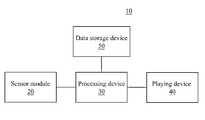
- FIG. 1 is a system block diagram of a recognition system.
- the recognition system 10 comprises a sensor module 20 , a processing device 30 , a playing device 40 , and a data storage device 50 .
- the sensor module 20 is used for generating a first sensing signal according to an operation of a user.
- the operation of the user is a body or facial action, for example, the user approaches the sensor module 20 with the face or the user utters voice to the sensor module 20 .
- the first sensing signal is an electronic signal, and the electronic signal represents a feature of the operation of user, for example, the bright and dark changes of the facial contour of the user or the amplitude of the voice signal.
- the processing device 30 is electrically connected to the sensor module 20 , and is used for receiving the first sensing signal.
- the processing device 30 generates a recognition result in response to the first sensing signal.
- the processing device 30 analyzes the first sensing signal to obtain a plurality of feature values. Subsequently, the feature values are then compared with a preset value to obtain the recognition result.
- the recognition result may represent an identity of the user (a name or a code of the user), or information (race or gender) represented by the user.
- the playing device 40 is electrically connected to the processing device 30 , and may receive the recognition result. After receiving the recognition result, the playing device 40 plays the recognition result, so that the user may know the result right away. In addition, the playing device 40 may also prompt a response that the user can make to the recognition result after knowing the recognition result. For example, the playing device 40 may prompt that the user nods the head when thinking that the recognition result is correct and shakes the head when thinking that the recognition result is fault.
- the data storage device 50 may be a medium capable of storing digital data, such as a non-volatile memory, a hard disk, or a disk array.
- the data storage device 50 stores a plurality of objects, and the objects may correspond to image features or voice features of the user.
- the processing device 30 compares the first sensing signal with the plurality of objects, so as to generate a recognition result.
- the sensor module 20 After the recognition result is played, the sensor module 20 is used for recognizing a response of the user. The sensor module 20 further generates a second sensing signal according to the response of the user. The second sensing signal is fed back to the processing device 30 , so the processing device 30 judges whether the recognition result is correct or acceptable according to the second sensing signal. That is to say, if the sensor module 20 recognizes that the second sensing signal satisfies a first preset feature (for example, nodding the head), it is judged that the recognition result is correct. When the sensor module 20 recognizes that the second sensing signal satisfies a second preset feature (for example, shaking the head), it is judged that the recognition result is fault. The processing device updates the data storage device according to the judged recognition result. Therefore, the recognition system 10 can correct a future judgment result according to whether the judgment result is correct or fault, so as to increase the judgment accuracy.
- a first preset feature for example, nodding the head
- a second preset feature for example, shaking the
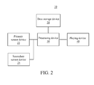
- FIG. 2 is a detailed block diagram of a recognition system according to the present invention.
- the recognition system 10 comprises a primary sensor device 22 , a secondary sensor device 24 , a processing device 30 , a playing device 40 , and a data storage device 50 .
- the sensor module 20 comprises the primary sensor device 22 and the secondary sensor device 24 , which are respectively used for recognizing the operation and response of the user.
- the primary sensor device 22 is used for recognizing an operation of a user and generating a first sensing signal.
- the secondary sensor device 24 is used for recognizing a response of the user and generating a second sensing signal after the recognition result is played.
- the primary sensor device 22 is an image sensor or a voice sensor device.
- the image sensor is used for generating an image signal.
- the image sensor may be a charge-coupled device (CCD) or a Complementary Metal Oxide Semiconductor (CMOS).
- CMOS Complementary Metal Oxide Semiconductor
- the image sensor can convert an optical signal into an electric signal for ease of storage, transmission, or operation.
- the voice sensor is used for generating a voice signal.
- the voice sensor may be a microphone, and the voice sensor can convert a sound wave signal into an electric signal for ease of storage, transmission, or operation.
- the objects stored in the data storage device 50 represent image features.
- the processing device 30 compares the image signal generated by the primary sensor device 22 with the plurality of objects in the data storage device 50 , and selects one in the plurality of objects most similar to the image signal as the recognition result.
- the processing device 30 may perform difference calculation on the color value, gradient value or image frequency feature of the image signal and the plurality of objects in the data storage device 50 .
- the object with the minimum difference may be regarded as the most similar object.
- the playing device 40 is a display screen.
- the display screen may be, but not limited to, a Liquid Crystal Display (LCD), an Organic Light Emitting Diode (OLED), or an e-paper.
- the display screen is used for displaying the recognition result, for example, displaying the name of or the number represented by the user.
- the objects stored in the data storage device 50 represent voice features.
- the processing device 30 compares a voice signal and the plurality of objects in the data storage device 50 , and in the plurality of objects, selects one most similar to the voice signal as the recognition result.
- the processing device 30 may perform difference calculation on the sound waves or the frequency features of the voice signal and the plurality of objects in the data storage device 50 .
- the object with the minimum difference is regarded as the most similar object.
- the playing device 40 is a loudspeaker.
- the loudspeaker is used for emitting a voice, so as to play the recognition result, for example, read the name or number of the user.
- the secondary sensor device 24 may be a touch sensor or a non-touch sensor.
- the touch sensor may comprise a mouse, a keyboard, or a touch screen, so as to be touched by the user and recognize an operation of a user.
- the user may input with the secondary sensor device 24 to represent whether the recognition result is correct or fault. For example, the user may input “Y” with the keyboard, so as to represent the correct recognition result, and input “N” to represent the fault recognition result.
- the non-touch sensor may be a sound sensor, an image sensor, or a brain wave sensor, so the user responds to the recognition result without touching the secondary sensor device.
- the image sensor device may detect the body action and facial expression of the user
- the sound sensor may detect the sound uttered by the user
- the brain wave sensor may detect the brain wave of the user, so as to judge whether the recognition result is correct.
- the image sensor may detect the behavior of the user, the user draws a circle with the hand, representing the correct recognition result, and the user draws a cross with the hand, representing the fault recognition result.
- the secondary sensor device 24 may also be a physiological signal sensor.
- the secondary sensor device 24 may detect the physiological response that the user is unable to control voluntarily, comprising changes such as heartbeats, breath, blood pressure, and brain waves. Compared to the voluntarily controlled responses such as gestures and voices, the physiological signal is more difficult to pretend. Therefore, the cheating of the user may be prevented.
- the processing device 30 may select, in the plurality of objects, several objects having the similarity reaching a threshold value, and calculates a first confidence value according to the similarity. For example, the processing device 30 may select Objects A, B, and C, the first confidence value of Object A is “70”, the first confidence value of Object B is “20”, and the first confidence value of Object C is “10”.
- the sensor device 20 (or the secondary sensor device 24 ) further respectively generates a second confidence value according to responses of the user to Objects A, B, and C.
- the second confidence value of Object A is “50”
- the second confidence value of Object B is “10”
- the second confidence value of Object C is “5”.
- the processing device 30 further generates the recognition result corresponding to the first confidence value and the second confidence value.
- the processing device 30 may have the first confidence value and the second confidence value multiplied or added to obtain an integrated value.
- the processing device 30 judges whether the displayed Objects A, B, and C are correct recognition results according to the integrated values.
- the processing device 30 may set a critical value. When the integrated value reaches the critical value, it is judged that the recognition result is correct. Therefore, the possibility that the user increases the second confidence value on purpose to confuse the recognition system 10 to generate an fault recognition result is avoided.
- the recognition system of the present invention is described in FIGS. 1 and 2 .
- FIGS. 3 to 6 the recognition method of the present invention is described, and the recognition method may be implemented by the recognition system in FIGS. 1 and 2 .
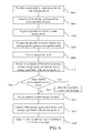
- FIG. 3 is a first flow chart of a recognition method according to an embodiment of the present invention.
- Step S 101 a sensor module 20 , a processing device 30 , and a playing device 40 are provided.
- the sensor module 20 may include a primary sensor device 22 and a secondary sensor device 24 .
- Step S 103 the sensor module 20 may generate a first sensing signal.
- the sensor module 20 transmits the first sensing signal to the processing device 30 .
- Step S 105 a plurality of objects in the data storage device 50 are acquired.
- the objects represent image features or voice features.
- Step S 106 the processing device 30 compares the plurality of objects to generate a recognition result in response to the first sensing signal.
- the processing device 30 may analyze the first sensing signal to obtain a plurality of feature values, and generates the recognition result by using the feature values.
- Step S 107 the playing device 40 plays the recognition result. Therefore, the user may judge whether the recognition result corresponding to the first sensing signal is correct according to the picture displayed or the sound emitted by the playing device 40 .
- Step S 109 when the user sees the picture displayed or hears the sound emitted by the playing device 40 , the sensor module 20 may recognizes a response of the user, so as to generate a second sensing signal. The sensor module 20 feeds the second sensing signal back to the processing device.
- Step S 111 the processing device 30 judges whether the recognition result is correct according to the second sensing signal, that is, according to the response of the user.
- FIG. 4 is a second flow chart of a recognition method according to the present invention. Steps S 201 to S 206 are same as Steps S 101 to S 106 .
- Step 207 the processing device 30 may select, in a plurality of objects, several object having the similarity reaching a threshold value, and calculate a first confidence value according to the similarity.
- Steps S 208 and S 209 are same as Steps S 107 and S 109 .
- Step S 210 the processing device 30 generates a second confidence value according to the second sensing signal generated through the response of the user.
- Step S 211 the processing device 30 generates an integrated value corresponding to the first confidence value and the second confidence value, and judges the recognition result according to the integrated value.
- FIG. 5 is a third flow chart of a recognition method according to the present invention.
- Steps S 301 , S 303 , S 305 , and S 307 are same as Steps S 201 , S 203 , S 205 , and S 206 .
- Step S 309 a reliable area of the first sensing signal is selected.
- a first sensing signal for example, a human face is first displayed on the screen.
- the human face may present a phenomenon of partially too bright or partially too dark due to influences of the environment light rays.
- the user may select a part with normal exposure on the screen, so as to increase the probability of correct recognition.
- Step S 311 the processing device 30 compares the selected reliable area with the plurality of objects, so as to generate a recognition result.
- Steps S 313 , S 315 , S 317 and Steps S 208 , S 209 , and S 211 are the same.
- FIG. 6 is a flow chart of a recognition method according to a fourth embodiment of the present invention.
- Steps S 401 to S 411 are same as Steps S 201 to S 211 .
- Step S 413 the processing device 30 judges whether the recognition result is correct according to the second sensing signal obtained in Step S 411 . If the judgment result is correct, Step S 414 is performed; and if the judgment result is fault, Step S 415 is performed.
- Step S 414 the recognition result being judged correct is stored in the data storage device 50 , so as to increase the recognition accuracy.
- Step S 415 as the recognition result is judged fault, the processing device 30 further generates another recognition result.
- the other recognition result is one or more objects most similar to the first sensing signal in the plurality of objects in the data storage device other than the recognition result being judged fault.
- Step S 417 the sensor module 20 recognizes a response of the user, so as to generate a third sensing signal.
- the third sensing signal is fed back to the processing device.
- Step S 419 the processing device 30 judges whether the other recognition result is correct according to the third sensing signal.
- Step 419 if it is judged that the other recognition result is correct, the processing device 30 synchronously determines whether the similarity between the other recognition result and the first sensing signal is higher than a threshold value. When the judgments above are both correct, it is considered that the final recognition result is correct.
- the recognition result may be first played to the user, so the user can know the recognition result in advance.
- the recognition system can detect the response of the user to the recognition result, so as to determine whether the recognition result is correct. Therefore, the recognition system of the present invention is able to effectively increase the detection accuracy.
Abstract
Description
- This non-provisional application claims priority under 35 U.S.C. §119(a) on Patent Application No. 100111140 filed in Taiwan, R.O.C. on Mar. 30, 2011, the entire contents of which are hereby incorporated by reference.
- 1. Field of Invention
- The present invention relates to a recognition system and a recognition method, and more particularly to a recognition system and a recognition method capable of recognizing an operation of a user.
- 2. Related Art
- With the ongoing development of the digital technologies, a biological feature recognition system is currently widely applied. For example, the biological feature recognition system is capable of sampling features of a user such as fingerprints, irises, facial patterns or voice prints, and performing analysis and comparison, so as to judge a practical identity of the user.
- The biological feature recognition system can be used for access control and security, medical care, or robots. In combination with the identity recognition of the user, various personal and automatic services are performed, so as to save the labor cost.
- The recognition system comprises a sensor module, a processing device, a playing device, and a data storage device.
- The sensor module is used for generating a first sensing signal according to an operation of a user. The data storage device storage has a plurality of objects. The processing device compares the first sensing signal with the plurality of objects to generate a recognition result in response to the first sensing signal. The playing device is used for playing the recognition result. The sensor module is used for, after the recognition result is played, recognizing a response of the user to generate a second sensing signal, and feeding the second sensing signal back to the processing device. The processing device judges whether the recognition result is acceptable or correct according to the second sensing signal.
- The sensor module has a primary sensor device and a secondary sensor device. The primary sensor device is used for recognizing the operation of the user and generating the first sensing signal, and the secondary sensor device is used for recognizing the response of the user and generating the second sensing signal.
- The disclosure further provides a recognition method, which comprises: providing a sensor module, a processing device, and a playing device; acquiring a plurality of objects in a data storage device; generating, by the sensor module, a first sensing signal according to an operation of a user; comparing, by the processing device, a plurality of objects and the first sensing signal, so as to generate a recognition result in response to the first sensing signal; playing, by the playing device, the recognition result; recognizing, by the sensor module, a response of the user to generate a second sensing signal, and feeding the second sensing signal back to the processing device; and judging whether the recognition result is acceptable according to the second sensing signal.
- The disclosure will become more fully understood from the detailed description given herein below for illustration only, and thus are not limitative of the present invention, and wherein:
-
FIG. 1 is a system block diagram of a recognition system according to a first embodiment; -
FIG. 2 is a system block diagram of a recognition system according to a second embodiment; -
FIG. 3 is a first flow chart of a recognition method; -
FIG. 4 is a second flow chart of a recognition method; -
FIG. 5 is a third flow chart of a recognition method; and -
FIG. 6 is a fourth flow chart of a recognition method. -
FIG. 1 is a system block diagram of a recognition system. Therecognition system 10 comprises asensor module 20, aprocessing device 30, aplaying device 40, and adata storage device 50. - The
sensor module 20 is used for generating a first sensing signal according to an operation of a user. The operation of the user is a body or facial action, for example, the user approaches thesensor module 20 with the face or the user utters voice to thesensor module 20. The first sensing signal is an electronic signal, and the electronic signal represents a feature of the operation of user, for example, the bright and dark changes of the facial contour of the user or the amplitude of the voice signal. - The
processing device 30 is electrically connected to thesensor module 20, and is used for receiving the first sensing signal. Theprocessing device 30 generates a recognition result in response to the first sensing signal. Theprocessing device 30 analyzes the first sensing signal to obtain a plurality of feature values. Subsequently, the feature values are then compared with a preset value to obtain the recognition result. The recognition result may represent an identity of the user (a name or a code of the user), or information (race or gender) represented by the user. - The
playing device 40 is electrically connected to theprocessing device 30, and may receive the recognition result. After receiving the recognition result, theplaying device 40 plays the recognition result, so that the user may know the result right away. In addition, theplaying device 40 may also prompt a response that the user can make to the recognition result after knowing the recognition result. For example, theplaying device 40 may prompt that the user nods the head when thinking that the recognition result is correct and shakes the head when thinking that the recognition result is fault. - The
data storage device 50 may be a medium capable of storing digital data, such as a non-volatile memory, a hard disk, or a disk array. Thedata storage device 50 stores a plurality of objects, and the objects may correspond to image features or voice features of the user. Theprocessing device 30 compares the first sensing signal with the plurality of objects, so as to generate a recognition result. - After the recognition result is played, the
sensor module 20 is used for recognizing a response of the user. Thesensor module 20 further generates a second sensing signal according to the response of the user. The second sensing signal is fed back to theprocessing device 30, so theprocessing device 30 judges whether the recognition result is correct or acceptable according to the second sensing signal. That is to say, if thesensor module 20 recognizes that the second sensing signal satisfies a first preset feature (for example, nodding the head), it is judged that the recognition result is correct. When thesensor module 20 recognizes that the second sensing signal satisfies a second preset feature (for example, shaking the head), it is judged that the recognition result is fault. The processing device updates the data storage device according to the judged recognition result. Therefore, therecognition system 10 can correct a future judgment result according to whether the judgment result is correct or fault, so as to increase the judgment accuracy. -
FIG. 2 is a detailed block diagram of a recognition system according to the present invention. Therecognition system 10 comprises aprimary sensor device 22, asecondary sensor device 24, aprocessing device 30, aplaying device 40, and adata storage device 50. - In this embodiment, the
sensor module 20 comprises theprimary sensor device 22 and thesecondary sensor device 24, which are respectively used for recognizing the operation and response of the user. Theprimary sensor device 22 is used for recognizing an operation of a user and generating a first sensing signal. Thesecondary sensor device 24 is used for recognizing a response of the user and generating a second sensing signal after the recognition result is played. - The
primary sensor device 22 is an image sensor or a voice sensor device. The image sensor is used for generating an image signal. The image sensor may be a charge-coupled device (CCD) or a Complementary Metal Oxide Semiconductor (CMOS). The image sensor can convert an optical signal into an electric signal for ease of storage, transmission, or operation. The voice sensor is used for generating a voice signal. The voice sensor may be a microphone, and the voice sensor can convert a sound wave signal into an electric signal for ease of storage, transmission, or operation. - When the
primary sensor device 22 is an image sensor, the objects stored in thedata storage device 50 represent image features. Theprocessing device 30 compares the image signal generated by theprimary sensor device 22 with the plurality of objects in thedata storage device 50, and selects one in the plurality of objects most similar to the image signal as the recognition result. Theprocessing device 30 may perform difference calculation on the color value, gradient value or image frequency feature of the image signal and the plurality of objects in thedata storage device 50. The object with the minimum difference may be regarded as the most similar object. - At this time, the playing
device 40 is a display screen. The display screen may be, but not limited to, a Liquid Crystal Display (LCD), an Organic Light Emitting Diode (OLED), or an e-paper. The display screen is used for displaying the recognition result, for example, displaying the name of or the number represented by the user. - When the
primary sensor device 22 is a voice sensor, the objects stored in thedata storage device 50 represent voice features. Theprocessing device 30 compares a voice signal and the plurality of objects in thedata storage device 50, and in the plurality of objects, selects one most similar to the voice signal as the recognition result. Theprocessing device 30 may perform difference calculation on the sound waves or the frequency features of the voice signal and the plurality of objects in thedata storage device 50. The object with the minimum difference is regarded as the most similar object. - In this embodiment, the playing
device 40 is a loudspeaker. The loudspeaker is used for emitting a voice, so as to play the recognition result, for example, read the name or number of the user. - The
secondary sensor device 24 may be a touch sensor or a non-touch sensor. The touch sensor may comprise a mouse, a keyboard, or a touch screen, so as to be touched by the user and recognize an operation of a user. After seeing the display or hearing the played recognition result, the user may input with thesecondary sensor device 24 to represent whether the recognition result is correct or fault. For example, the user may input “Y” with the keyboard, so as to represent the correct recognition result, and input “N” to represent the fault recognition result. - Furthermore, the non-touch sensor may be a sound sensor, an image sensor, or a brain wave sensor, so the user responds to the recognition result without touching the secondary sensor device. The image sensor device may detect the body action and facial expression of the user, the sound sensor may detect the sound uttered by the user, and the brain wave sensor may detect the brain wave of the user, so as to judge whether the recognition result is correct. For example, the image sensor may detect the behavior of the user, the user draws a circle with the hand, representing the correct recognition result, and the user draws a cross with the hand, representing the fault recognition result.
- In addition, the
secondary sensor device 24 may also be a physiological signal sensor. Thesecondary sensor device 24 may detect the physiological response that the user is unable to control voluntarily, comprising changes such as heartbeats, breath, blood pressure, and brain waves. Compared to the voluntarily controlled responses such as gestures and voices, the physiological signal is more difficult to pretend. Therefore, the cheating of the user may be prevented. - In addition to the embodiment, the
processing device 30 may select, in the plurality of objects, several objects having the similarity reaching a threshold value, and calculates a first confidence value according to the similarity. For example, theprocessing device 30 may select Objects A, B, and C, the first confidence value of Object A is “70”, the first confidence value of Object B is “20”, and the first confidence value of Object C is “10”. - The sensor device 20 (or the secondary sensor device 24) further respectively generates a second confidence value according to responses of the user to Objects A, B, and C. For example, the second confidence value of Object A is “50”, the second confidence value of Object B is “10”, and the second confidence value of Object C is “5”.
- Subsequently, the
processing device 30 further generates the recognition result corresponding to the first confidence value and the second confidence value. In this embodiment, theprocessing device 30 may have the first confidence value and the second confidence value multiplied or added to obtain an integrated value. Theprocessing device 30 judges whether the displayed Objects A, B, and C are correct recognition results according to the integrated values. - In order to further increase the reliability in use, the
processing device 30 may set a critical value. When the integrated value reaches the critical value, it is judged that the recognition result is correct. Therefore, the possibility that the user increases the second confidence value on purpose to confuse therecognition system 10 to generate an fault recognition result is avoided. - The recognition system of the present invention is described in
FIGS. 1 and 2 . InFIGS. 3 to 6 , the recognition method of the present invention is described, and the recognition method may be implemented by the recognition system inFIGS. 1 and 2 . -
FIG. 3 is a first flow chart of a recognition method according to an embodiment of the present invention. - In Step S101, a
sensor module 20, aprocessing device 30, and aplaying device 40 are provided. Thesensor module 20 may include aprimary sensor device 22 and asecondary sensor device 24. - In Step S103, according to an operation of a user, the
sensor module 20 may generate a first sensing signal. Thesensor module 20 transmits the first sensing signal to theprocessing device 30. - In Step S105, a plurality of objects in the
data storage device 50 are acquired. The objects represent image features or voice features. - In Step S106, the
processing device 30 compares the plurality of objects to generate a recognition result in response to the first sensing signal. Theprocessing device 30 may analyze the first sensing signal to obtain a plurality of feature values, and generates the recognition result by using the feature values. - In Step S107, the playing
device 40 plays the recognition result. Therefore, the user may judge whether the recognition result corresponding to the first sensing signal is correct according to the picture displayed or the sound emitted by the playingdevice 40. - In Step S109, when the user sees the picture displayed or hears the sound emitted by the playing
device 40, thesensor module 20 may recognizes a response of the user, so as to generate a second sensing signal. Thesensor module 20 feeds the second sensing signal back to the processing device. - In Step S111, the
processing device 30 judges whether the recognition result is correct according to the second sensing signal, that is, according to the response of the user. -
FIG. 4 is a second flow chart of a recognition method according to the present invention. Steps S201 to S206 are same as Steps S101 to S106. - In Step 207, the
processing device 30 may select, in a plurality of objects, several object having the similarity reaching a threshold value, and calculate a first confidence value according to the similarity. Steps S208 and S209 are same as Steps S107 and S109. - In Step S210, the
processing device 30 generates a second confidence value according to the second sensing signal generated through the response of the user. - In Step S211, the
processing device 30 generates an integrated value corresponding to the first confidence value and the second confidence value, and judges the recognition result according to the integrated value. -
FIG. 5 is a third flow chart of a recognition method according to the present invention. - Steps S301, S303, S305, and S307 are same as Steps S201, S203, S205, and S206.
- In Step S309, a reliable area of the first sensing signal is selected. For example, before Step 309, a first sensing signal, for example, a human face is first displayed on the screen. The human face may present a phenomenon of partially too bright or partially too dark due to influences of the environment light rays. The user may select a part with normal exposure on the screen, so as to increase the probability of correct recognition.
- In Step S311, the
processing device 30 compares the selected reliable area with the plurality of objects, so as to generate a recognition result. - Steps S313, S315, S317 and Steps S208, S209, and S211 are the same.
-
FIG. 6 is a flow chart of a recognition method according to a fourth embodiment of the present invention. - Steps S401 to S411 are same as Steps S201 to S211.
- In Step S413, the
processing device 30 judges whether the recognition result is correct according to the second sensing signal obtained in Step S411. If the judgment result is correct, Step S414 is performed; and if the judgment result is fault, Step S415 is performed. - In Step S414, the recognition result being judged correct is stored in the
data storage device 50, so as to increase the recognition accuracy. - In Step S415, as the recognition result is judged fault, the
processing device 30 further generates another recognition result. The other recognition result is one or more objects most similar to the first sensing signal in the plurality of objects in the data storage device other than the recognition result being judged fault. - In Step S417, the
sensor module 20 recognizes a response of the user, so as to generate a third sensing signal. The third sensing signal is fed back to the processing device. - In Step S419, the
processing device 30 judges whether the other recognition result is correct according to the third sensing signal. In Step 419, if it is judged that the other recognition result is correct, theprocessing device 30 synchronously determines whether the similarity between the other recognition result and the first sensing signal is higher than a threshold value. When the judgments above are both correct, it is considered that the final recognition result is correct. - Through the recognition system and the recognition method, the recognition result may be first played to the user, so the user can know the recognition result in advance. In addition, the recognition system can detect the response of the user to the recognition result, so as to determine whether the recognition result is correct. Therefore, the recognition system of the present invention is able to effectively increase the detection accuracy.
- The present invention may be embodied in other specific forms without departing from its spirit or essential characteristics. The described embodiments are to be considered in all respects only as illustrative and not restrictive. The scope of the invention is, therefore, indicated by the appended claims rather than by the foregoing description. All changes which come within the meaning and range of equivalency of the claims are to be embraced within their scope.
Claims (18)
Applications Claiming Priority (3)
| Application Number | Priority Date | Filing Date | Title |
|---|---|---|---|
| TW100111140 | 2011-03-30 | ||
| TW100111140A TWI476704B (en) | 2011-03-30 | 2011-03-30 | Recognizing devices and methods |
| TW100111140A | 2011-03-30 |
Publications (2)
| Publication Number | Publication Date |
|---|---|
| US20120249293A1 true US20120249293A1 (en) | 2012-10-04 |
| US8810362B2 US8810362B2 (en) | 2014-08-19 |
Family
ID=46926448
Family Applications (1)
| Application Number | Title | Priority Date | Filing Date |
|---|---|---|---|
| US13/239,855 Active 2032-03-29 US8810362B2 (en) | 2011-03-30 | 2011-09-22 | Recognition system and recognition method |
Country Status (2)
| Country | Link |
|---|---|
| US (1) | US8810362B2 (en) |
| TW (1) | TWI476704B (en) |
Cited By (2)
| Publication number | Priority date | Publication date | Assignee | Title |
|---|---|---|---|---|
| US20180335409A1 (en) * | 2017-05-17 | 2018-11-22 | Delta Electronics, Inc. | Testing system and method for air sensing device |
| WO2019059581A1 (en) * | 2017-09-21 | 2019-03-28 | 삼성전자 주식회사 | Electronic device for processing user speech and control method for electronic device |
Families Citing this family (4)
| Publication number | Priority date | Publication date | Assignee | Title |
|---|---|---|---|---|
| TWI490792B (en) * | 2012-10-22 | 2015-07-01 | Pixart Imaging Inc | User recognition and confirmation device and method, and central control system for vehicles using the same |
| TW201419036A (en) | 2012-11-06 | 2014-05-16 | Pixart Imaging Inc | Sensor array and method of controlling sensing device and related electronic apparatus |
| CN104881656B (en) * | 2015-06-04 | 2018-05-04 | 江西合力泰科技有限公司 | A kind of pressurizer for fingerprint recognition module |
| TWI717425B (en) * | 2016-12-01 | 2021-02-01 | 易思醫創有限公司 | Physiological sensor system for distinguishing personal characteristic |
Citations (6)
| Publication number | Priority date | Publication date | Assignee | Title |
|---|---|---|---|---|
| US5844824A (en) * | 1995-10-02 | 1998-12-01 | Xybernaut Corporation | Hands-free, portable computer and system |
| US6480825B1 (en) * | 1997-01-31 | 2002-11-12 | T-Netix, Inc. | System and method for detecting a recorded voice |
| US20090034805A1 (en) * | 2006-05-10 | 2009-02-05 | Aol Llc | Using Relevance Feedback In Face Recognition |
| US20090055193A1 (en) * | 2007-02-22 | 2009-02-26 | Pudding Holdings Israel Ltd. | Method, apparatus and computer code for selectively providing access to a service in accordance with spoken content received from a user |
| US20090238419A1 (en) * | 2007-03-05 | 2009-09-24 | Fotonation Ireland Limited | Face recognition training method and apparatus |
| US7826464B2 (en) * | 2007-01-10 | 2010-11-02 | Mikhail Fedorov | Communication system |
Family Cites Families (7)
| Publication number | Priority date | Publication date | Assignee | Title |
|---|---|---|---|---|
| GB2372131A (en) | 2001-02-10 | 2002-08-14 | Hewlett Packard Co | Face recognition and information system |
| US6920236B2 (en) | 2001-03-26 | 2005-07-19 | Mikos, Ltd. | Dual band biometric identification system |
| US7737861B2 (en) * | 2001-06-19 | 2010-06-15 | Paxflow Holdings Pte Ltd. | Location, communication and tracking systems |
| SG123618A1 (en) | 2004-12-15 | 2006-07-26 | Chee Khin George Loo | A method and system for verifying the identity of a user |
| US8918162B2 (en) * | 2007-04-17 | 2014-12-23 | Francine J. Prokoski | System and method for using three dimensional infrared imaging to provide psychological profiles of individuals |
| US7894639B2 (en) * | 2008-01-03 | 2011-02-22 | International Business Machines Corporation | Digital life recorder implementing enhanced facial recognition subsystem for acquiring a face glossary data |
| TWM394539U (en) * | 2010-08-11 | 2010-12-11 | Taiwan Shinkong Security Co Ltd | Security apparatus controlled by waving hands |
-
2011
- 2011-03-30 TW TW100111140A patent/TWI476704B/en active
- 2011-09-22 US US13/239,855 patent/US8810362B2/en active Active
Patent Citations (7)
| Publication number | Priority date | Publication date | Assignee | Title |
|---|---|---|---|---|
| US5844824A (en) * | 1995-10-02 | 1998-12-01 | Xybernaut Corporation | Hands-free, portable computer and system |
| US6480825B1 (en) * | 1997-01-31 | 2002-11-12 | T-Netix, Inc. | System and method for detecting a recorded voice |
| US20090034805A1 (en) * | 2006-05-10 | 2009-02-05 | Aol Llc | Using Relevance Feedback In Face Recognition |
| US7826464B2 (en) * | 2007-01-10 | 2010-11-02 | Mikhail Fedorov | Communication system |
| US20090055193A1 (en) * | 2007-02-22 | 2009-02-26 | Pudding Holdings Israel Ltd. | Method, apparatus and computer code for selectively providing access to a service in accordance with spoken content received from a user |
| US20090238419A1 (en) * | 2007-03-05 | 2009-09-24 | Fotonation Ireland Limited | Face recognition training method and apparatus |
| US8363951B2 (en) * | 2007-03-05 | 2013-01-29 | DigitalOptics Corporation Europe Limited | Face recognition training method and apparatus |
Cited By (3)
| Publication number | Priority date | Publication date | Assignee | Title |
|---|---|---|---|---|
| US20180335409A1 (en) * | 2017-05-17 | 2018-11-22 | Delta Electronics, Inc. | Testing system and method for air sensing device |
| US10598645B2 (en) * | 2017-05-17 | 2020-03-24 | Delta Electronics, Inc. | Testing system and method for air sensing device |
| WO2019059581A1 (en) * | 2017-09-21 | 2019-03-28 | 삼성전자 주식회사 | Electronic device for processing user speech and control method for electronic device |
Also Published As
| Publication number | Publication date |
|---|---|
| TWI476704B (en) | 2015-03-11 |
| TW201239780A (en) | 2012-10-01 |
| US8810362B2 (en) | 2014-08-19 |
Similar Documents
| Publication | Publication Date | Title |
|---|---|---|
| Fenu et al. | A multi-biometric system for continuous student authentication in e-learning platforms | |
| US11580203B2 (en) | Method and apparatus for authenticating a user of a computing device | |
| US8810362B2 (en) | Recognition system and recognition method | |
| JP4407714B2 (en) | Biometric authentication device and biometric authentication method | |
| KR100947990B1 (en) | Gaze Tracking Apparatus and Method using Difference Image Entropy | |
| US11210376B2 (en) | Systems and methods for biometric user authentication | |
| CN105631406B (en) | Image recognition processing method and device | |
| WO2019210796A1 (en) | Speech recognition method and apparatus, storage medium, and electronic device | |
| US20160103487A1 (en) | Brain computer interface (bci) system based on gathered temporal and spatial patterns of biophysical signals | |
| CN110287918B (en) | Living body identification method and related product | |
| KR101288447B1 (en) | Gaze tracking apparatus, display apparatus and method therof | |
| JP7131761B2 (en) | Method and apparatus for birefringence-based biometric authentication | |
| KR20190113252A (en) | Method for eye-tracking and terminal for executing the same | |
| KR20210060246A (en) | The arraprus for obtaining biometiric data and method thereof | |
| US11636188B2 (en) | Combining biometrics, hidden knowledge and intent to authenticate | |
| US20200178840A1 (en) | Method and device for marking adventitious sounds | |
| KR102526951B1 (en) | Method and apparatus for measuring biometric information in electronic device | |
| JP7021488B2 (en) | Information processing equipment and programs | |
| TWI730589B (en) | Optical living body feature detection method and biological feature acquisition device and information processing device using the same | |
| CN115736939A (en) | Atrial fibrillation disease probability generation method and device, electronic equipment and storage medium | |
| JP4872767B2 (en) | Biometric authentication device and biometric authentication method | |
| KR20230154380A (en) | System and method for providing heath-care services fitting to emotion states of users by behavioral and speaking patterns-based emotion recognition results | |
| JP5233152B2 (en) | Biometric authentication device and biometric authentication method | |
| CN113764099A (en) | Psychological state analysis method, device, equipment and medium based on artificial intelligence | |
| KR20180075221A (en) | Electric apparatus and operation method thereof |
Legal Events
| Date | Code | Title | Description |
|---|---|---|---|
| AS | Assignment |
Owner name: PIXART IMAGING INC., TAIWAN Free format text: ASSIGNMENT OF ASSIGNORS INTEREST;ASSIGNORS:CHEN, YU-HAN;KAO, MING-TSAN;LU, CHIH-HUNG;REEL/FRAME:026947/0963 Effective date: 20110901 |
|
| STCF | Information on status: patent grant |
Free format text: PATENTED CASE |
|
| FEPP | Fee payment procedure |
Free format text: ENTITY STATUS SET TO UNDISCOUNTED (ORIGINAL EVENT CODE: BIG.) |
|
| MAFP | Maintenance fee payment |
Free format text: PAYMENT OF MAINTENANCE FEE, 4TH YEAR, LARGE ENTITY (ORIGINAL EVENT CODE: M1551) Year of fee payment: 4 |
|
| MAFP | Maintenance fee payment |
Free format text: PAYMENT OF MAINTENANCE FEE, 8TH YEAR, LARGE ENTITY (ORIGINAL EVENT CODE: M1552); ENTITY STATUS OF PATENT OWNER: LARGE ENTITY Year of fee payment: 8 |