US20120249305A1 - Wireless tag processor - Google Patents
Wireless tag processor Download PDFInfo
- Publication number
- US20120249305A1 US20120249305A1 US13/274,919 US201113274919A US2012249305A1 US 20120249305 A1 US20120249305 A1 US 20120249305A1 US 201113274919 A US201113274919 A US 201113274919A US 2012249305 A1 US2012249305 A1 US 2012249305A1
- Authority
- US
- United States
- Prior art keywords
- transmitting parts
- information
- radio waves
- reader
- tags
- Prior art date
- Legal status (The legal status is an assumption and is not a legal conclusion. Google has not performed a legal analysis and makes no representation as to the accuracy of the status listed.)
- Granted
Links
Images


Classifications
-
- G—PHYSICS
- G06—COMPUTING; CALCULATING OR COUNTING
- G06K—GRAPHICAL DATA READING; PRESENTATION OF DATA; RECORD CARRIERS; HANDLING RECORD CARRIERS
- G06K17/00—Methods or arrangements for effecting co-operative working between equipments covered by two or more of main groups G06K1/00 - G06K15/00, e.g. automatic card files incorporating conveying and reading operations
- G06K17/0022—Methods or arrangements for effecting co-operative working between equipments covered by two or more of main groups G06K1/00 - G06K15/00, e.g. automatic card files incorporating conveying and reading operations arrangements or provisious for transferring data to distant stations, e.g. from a sensing device
- G06K17/0025—Methods or arrangements for effecting co-operative working between equipments covered by two or more of main groups G06K1/00 - G06K15/00, e.g. automatic card files incorporating conveying and reading operations arrangements or provisious for transferring data to distant stations, e.g. from a sensing device the arrangement consisting of a wireless interrogation device in combination with a device for optically marking the record carrier
Definitions
- the present invention relates to a wireless tag processor.
- a wireless tag processor including a radio wave transmitting unit that has plural rows of transmitting part groups each having plural transmitting parts that transmit radio waves, the transmitting parts being aligned along a first direction, and the groups being provided in a second direction crossing the first direction, and that transmits radio waves to a wireless tag provided on a medium; and a control section that makes radio waves be transmitted from plural transmitting parts that is arranged staggered, among two rows of the transmitting parts included in the transmitting part groups that are adjacent to each other in the second direction crossing the first direction, and then, makes radio waves be transmitted from other transmitting parts included in the two rows of transmitting parts.
- FIG. 1 is a schematic configuration view showing a processing system in the present exemplary embodiment
- FIGS. 2A and 2B are views showing a sheet after image formation is made by an image forming apparatus
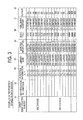
- FIG. 3 is a view showing examples of information stored in a data server
- FIG. 4 is a view for explaining a reader/writer apparatus
- FIG. 5 is a view for explaining the reader/writer apparatus
- FIG. 6 is a perspective view showing a first suppression unit along with sheets
- FIG. 7 is a plan view showing the first suppression unit along with sheets
- FIG. 8 is a perspective view showing the first suppression unit and a second suppression unit along with a belt member
- FIGS. 9A and 9B are views showing the first suppression unit or the like in an enlarged manner
- FIG. 10 is a flowchart showing the operation of the reader/writer apparatus
- FIGS. 11A to 11C are views for explaining reading processing of identification information, and writing processing of detailed information
- FIGS. 12A and 12B are views for explaining a comparative example of reading processing and writing processing
- FIG. 13 is a view for explaining a comparative example of reading processing and writing processing
- FIGS. 14A to 14D are a view for explaining a comparative example of reading processing and writing processing
- FIGS. 15A to 15C are views showing the processing when a reader/writer section fails
- FIG. 16A to 16C are views showing the processing when a reader/writer section fails.
- FIG. 17 is a flowchart for explaining the processing executed when a reader/writer section fails.
- FIG. 1 is a schematic configuration view showing a processing system in the present exemplary embodiment.
- this system is provided with an image forming apparatus 1 that forms an image on a sheet S in which plural wireless tags T (hereinafter referred to as “tags T”) are embedded, a reader/writer apparatus 2 that writes information in the tags T embedded in the sheet S or reads information from the tags T, and a data server 3 that stores the information written in the tags T and the information read from the tags T.
- this system is provided with a controller 4 that has a display panel 4 a that displays information, and receives age formation conditions in the image forming apparatus 1 , various conditions in the reader/writer apparatus 2 , the information written in the tags T, and the like.
- the controller 4 in the present exemplary embodiment is constituted by a personal computer (PC).
- an image is formed on the surface of a sheet S delivered from a factory or the like by the image forming apparatus 1 .
- the reader/writer apparatus 2 as an example of a wireless tag processor reads unique identification information (also referred to as identification number or a unique number (UID)) (hereinafter referred to as “identification information” in the present specification) that each tag T has, from each of the plural tags T embedded on the sheet S, and writes information to each tag T.
- the sheet S is delivered to a user or the like.
- the image forming apparatus 1 and the reader/writer apparatus 2 are separate apparatuses, but may be integrally formed.
- FIGS. 2A and 2B show the sheet S after image formation is made by the image forming apparatus 1 .
- a sheet S as an example of a medium is constituted by a base body B formed in a rectangular shape, and plural labels L 1 to L 8 (hereinafter referred to as “labels L”) that are provided so as to be detachable from the base body B.
- An adhesive is applied to the back of each of the plural labels L 1 to L 8 , and individual labels L is detached from the base body B, and is attached to, for example, a book (books), a DVD (Digital Versatile Disc), or a CD (Compact Disc).
- the individual labels L in the present exemplary embodiment are arranged in four rows in the longitudinal direction of the sheet S and in two rows in the lateral direction of the sheet S. Additionally, the individual labels L are arranged in the shape of a grid in 4 rows ⁇ 2 columns.
- the sheet S is transported along the lateral direction thereof in the image forming apparatus 1 and the reader/writer apparatus 2 .
- the sheet S which is formed in a rectangular shape and has a long side and a short side, is transported in a state where the long side becomes a leading edge.
- the number of sheets S that may be transported per unit time may be increased.
- the labels L in relation to the transporting direction of the sheet S, in the sheet S in the present exemplary embodiment, four labels L 5 to L 8 are provided downstream in the sheet transporting direction and four labels L 1 to L 4 are provided upstream in the sheet transporting direction.
- tags T 1 to T 8 are embedded in the labels L, respectively.
- a tag T 1 is embedded in the label L 1 .
- the tag T 1 in the present exemplary embodiment includes an antenna coil Ta, a capacitor for constituting a resonant circuit, and an IC chip Tc for storing information, as fundamental circuit elements.
- the capacitor may be incorporated into the antenna coil Ta, and may be built in the IC chip Tc.
- tags that are used as previously may be used as the tags T, and are not particularly limited.
- the tags T may be referred to as RFID tags, IC tags, non-contact data carriers, wireless IC tags, non-contact ICs, non-contact IC labels, non-contact IC tags, or the like.
- so-called passive tags that do not have a cell and develop electricity by radio waves from reader/writer sections that will be described later are used. It is noted that the tags are not limited to the passive tags, and so-called active tags equipped with a cell may also be used.
- the labels L are attached to books to be lent out in a library
- a bar code, and bar code information are printed using numerals on the surface of individual labels L.
- a sheet identification bar code BK for identifying a sheet S from other sheets is printed at one side portion in the lateral direction of the sheet S.
- the application of the tags T is not limited to the library only.
- the tags may be attached to rental DVDs, rental videos, or the like in rental shops. Additionally, in various factories, various stores, or the like the tags may be used for production management, stock management, or the like.
- the image forming apparatus 1 performs image formation on the surface of a sheet 5 , on the basis of information stored in the data server 3 .
- FIG. 3 shows examples of the information stored in the data server 3 .
- a library name 34 used as a collection location of books bar code information 35 , a book title 36 , a publishing company 37 , an author 38 , and the like are stored in a mutually associated state in the data server 3 .
- positional information (X, Y) 33 showing the forming position of each image is stored in the data server 3 .
- individual pieces of positional information 33 are also associated with the library name 34 , the bar code information 35 , the book title 36 , the publishing company 37 , the author 38 , and the like.
- identification information read from individual tags T in the reader/writer apparatus 2 is stored in the data server 3 (refer to reference numeral 32 ). In addition, this identification information is also stored so as to be associated with the library name 34 , the bar code information 35 , and the like.
- positional relationship between individual positions specified by the positional information 33 corresponds to (coincide with) the positional relationship between the individual labels L (individual tags T) arranged at the sheet S.
- positional information (X 1 , Y 1 ) corresponds to a label L 1
- positional information (X 1 , Y 2 ) corresponds to a label L 2
- positional information (X 1 , Y 3 ) corresponds to a label L 3
- positional information (X 1 , Y 4 ) corresponds to a label L 4 .
- positional information (X 2 , Y 1 ) corresponds to a label L 5
- positional information (X 2 , Y 2 ) corresponds to label L 6
- positional information (X 2 , Y 3 ) corresponds to label L 7
- positional information (X 2 , Y 4 ) corresponds to a label L 8 .
- the image forming apparatus 1 when the positional information 33 is (X 1 , Y 1 ), the image forming apparatus 1 performs image formation on the label L 1 , and for example, when the positional information 33 is (X 2 , Y 3 ), the image forming apparatus 1 performs image formation on the label L 7 .
- this positional information 33 may be automatically allocated by the data server 3 , for example, when information on the library name 34 or the like is stored in the data server 3 . Additionally, the positional information may be allocated by the controller 4 .
- sheet identification numbers for identifying a sheet S from other sheets S are stored in the data server 3 (refer to reference numeral 31 ).
- one sheet identification number is generated for eight pieces of information so as to correspond to the number (8) of labels L provided at one sheet S.
- this sheet identification number may be automatically allocated by the data server 3 , for example, when the library name 34 or the like is stored in the data server 3 . Additionally, the sheet identification number may be allocated by the controller 4 .
- the image forming apparatus 1 acquires one sheet's worth of information from the data server 3 .
- an image to be formed on the sheet S is generated on the basis of this information. More specifically, first, the image forming apparatus 1 generates a bar code on the basis of the bar code information 35 , generates an image in which the bar code, the bar code information 35 visualized as a number, and the library name as a character string are arranged in a preset relation, and arranges this image at a position corresponding to the positional information 33 . Then, the image forming apparatus 1 performs this processing for eight cases, and generates an overall image. Additionally, the image forming apparatus 1 generates a sheet identification bar code BK on the basis of the sheet identification number 31 , and generates an image obtained by combining the sheet identification bar code BK with the overall image.
- the image forming apparatus 1 forms the combined image on a sheet S positioned in a preset place.
- a character string “AA library” is printed on the label L 1 of the sheet S.
- a “bar code” and bar code information “123456789-1” visualized as a number are printed on the label L 1 .
- the sheet identification bar code BK in which a sheet identification number “200707010001” (refer to FIG. 3 ) is bar-coded is printed at the right end (one end in the sheet transporting direction) of the sheet S (refer to FIG. 2A ).
- the image forming apparatus 1 in the present exemplary embodiment adopts a so-called electrophotographic system, and forms electrostatic latent images based on image data for individual colors, for example, on photoreceptor drums provided corresponding to the individual colors, using exposure devices which are not shown. Thereafter, the image forming apparatus develops the electrostatic latent images, using individual color toners, and transfers toner images formed by this development onto a sheet S. Then, the toner images are fixed on the sheet S. Thereby, the sheet S on which information is printed is generated.
- a so-called ink jet system, a system using thermal paper, or the like may also be adopted in the image forming apparatus 1 .
- identification information is read from the individual tags Tin the reader/writer apparatus 2 . Additionally, information on the library name 34 , the bar code information 35 , the book title 36 , the publishing company 37 , and the author 38 is written in the individual tags T. In addition, in the present specification, the information written in the individual tags T is referred to as “detailed information” hereinbelow.
- FIGS. 4 and 5 are views for explaining the reader/writer apparatus 2 .
- the reader/writer apparatus 2 in the present exemplary embodiment includes an apparatus body portion 40 , and an opening and closing plate 41 that is provided at an upper part of the apparatus body portion 40 and is openably and closably attached to the apparatus body portion 40 . Additionally, the reader/writer apparatus 2 is provided with a stacking part 50 on which plural sheets S are stacked, and a pair of delivery rolls 51 that feeds out the sheets S one by one toward the inside of the apparatus body portion 40 from the stacked plural sheets S stacked on the stacking part 50 .
- the reader/writer apparatus 2 includes a pair of feed rolls 52 that further transports a sheet S fed-out by the delivery rolls 51 toward the downstream in the transporting direction, a first belt unit 53 and a second belt unit 54 that further transport the sheet S transported from the feed rolls 52 toward the downstream in the transporting direction, and an accommodating part 57 that stacks and accommodates the sheets S transported by the first belt unit 53 and the second belt unit 54 .
- the reader/writer apparatus 2 in the present exemplary embodiment has plural reader/writer sections 61 to 68 (only 61 and 68 are shown in the drawing) that read information from the tags T embedded in the sheet S, and writes information in the tags T.
- the reader/writer apparatus 2 includes a first suppression unit 71 and a second suppression unit 72 that suppress interference of radio waves transmitted from the reader/writer sections 61 to 68 .
- the reader/writer apparatus 2 is provided with a first sensor S 1 , a second sensor S 2 , third to sixth sensors S 3 to S 6 , and a seventh sensor S 7 that are provided along the transporting path of the sheet S, and performs predetermined output when the sheet S passes.
- the first sensor S 1 is arranged closer to the downstream in the sheet transporting direction than the feed rolls 52 , and is arranged closer to the upstream in the sheet transporting direction than the reading position by a bar code reader Br that will be described below.
- the second sensor S 2 is arranged closer to the downstream in the sheet transporting direction than the reading position by the code reader Br, and is arranged closer to the upstream in the sheet transporting direction than the second belt unit 54 .
- the third to sixth sensors S 3 to S 6 is arranged closer to the downstream in the sheet transporting direction than the second sensor S 2 , and is arranged closer to the upstream in the sheet transporting direction than the seventh sensor S 7 .
- the seventh sensor S 7 is arranged closer to the downstream in the sheet transporting direction than a nip portion N that will be described below.
- a bar code reader Br that reads the sheet identification bar code BK formed on the sheet S is provided closer to the downstream in the sheet transporting direction than a detection region by the first sensor S 1 in the reader/writer apparatus 2 .
- the reader/writer apparatus 2 includes a control section 91 that controls the respective sections (the respective apparatuses), and a transceiver section 92 that exchanges information among the data server 3 , the controller 4 , and the like.
- the first belt unit 53 that functions as a portion of transporting unit includes a belt member 53 a that is formed in an endless shape, first to fourth stretching rolls 53 b , 53 c , 53 d , and 53 e that stretch the belt member 53 a from the inside, and a tension roll 53 f that presses the belt member 53 a from the outside and imparts tension to the belt member 53 a .
- the first to fourth stretching rolls 53 b , 53 c , 53 d , and 53 e are arranged in a mutually separated state, and these four stretching rolls are provided so as to be arranged at individual apexes in a rectangle shape (oblong shape).
- the first stretching roll 53 b is arranged on the upstream in the sheet transporting direction and on the sheet transporting path side
- the second stretching roll 53 c is arranged on the upstream in the sheet transporting direction, and on a side separated from the sheet transporting path.
- the third stretching roll 53 d is arranged on the downstream in the sheet transporting direction and on the side separated from the sheet transporting path
- the fourth stretching roll 53 e is arranged on the downstream in the sheet transporting direction and on the sheet transporting path side.
- the second belt unit 54 is arranged above the first belt unit 53 (facing position). Additionally, the second belt unit 54 is arranged so as to be pressed against the first belt unit 53 , and forms a nip portion N (refer to FIG. 5 ) where a sheet S is transported while being pinched between the first belt unit 53 and the second belt unit 54 from above and below.
- the second belt unit 54 includes a belt member 54 a that is formed in an endless shape, and first to fourth stretching rolls 54 b , 54 c , 54 d , and 54 e that stretch the belt member 54 a from the inside.
- the belt member 54 a and the above belt member 53 a in the present exemplary embodiment are formed from a material (for example, a rubber member) that does not shield radio waves transmitted from antennas 61 a to 68 a that will be described below.
- the first to fourth stretching rolls 54 b , 54 c , 54 d , and 54 e are arranged in a mutually separated state, and these four stretching rolls are provided so as to be arranged at individual apexes in a rectangle shape (oblong shape).
- the space where the second suppression unit 72 is accommodated is formed inside the belt member 54 a .
- the nip portion N is formed as a flat portion in the belt member 53 a and a flat portion in the belt member 54 a come into contact with each other. For this reason, the transporting path in the nip portion N becomes flat.
- the second belt unit 54 and the second suppression unit 72 are movably provided so as to separate from the first belt unit 53 and the first suppression unit 71 , in conjunction with (accompanied with) the opening and closing of the opening and closing plate 41 . For this reason, the opening of the sheet transporting path is allowed, and when jamming or the like of a sheet S occurs in the sheet transporting path, the jammed sheet S may be simply and easily removed.
- FIG. 6 is a perspective view showing the first suppression unit 71 along with a sheet S
- FIG. 7 is a plan view showing the first suppression unit 71 with the sheet S.
- the first suppression unit 71 in the present exemplary embodiment includes an opening on a side where the sheet S is transported, and is formed in the shape of a box (a rectangular parallelepiped). Additionally, the first suppression unit 71 is arranged on one side of the transporting path of the sheet S.
- the first suppression unit 71 includes a first side wall 71 a formed along the transporting direction of the sheet S, a second side wall 71 b arranged at the facing position of this first side wall 71 a , a third side wall 71 c formed in a direction orthogonal to the transporting direction of the sheet S, and a fourth side wall 71 d formed similarly in the direction orthogonal to the transporting direction of the sheet S, and a bottom portion 71 e.
- the first suppression unit 71 includes a first partition member 71 k that partitions an internal space into two in the sheet transporting direction, and a second partition member 71 f , a third partition member 71 g , and a fourth partition member 71 h that partition the internal space into four in a direction orthogonal to the sheet transporting direction.
- the first suppression unit 71 in the present exemplary embodiment is brought into a state where closed spaces H 1 to H 8 closed except for the opening provided on the transporting path side of the sheet S are provided in the shape of a grid.
- the closed spaces H 1 to H 8 in the present exemplary embodiment are respectively arranged so as to face the individual tags T provided on the sheet S, when a transported sheet S is arranged (stopped) at a facing position of the first suppression unit 71 .
- the reader/writer sections 61 to 68 that write information in the tags T or read information from the tags T are provided in the closed spaces H 1 to H 8 , respectively.
- the individual reader/writer sections 61 to 68 in the present exemplary embodiment include antennas 61 a to 68 a as an example of transmitting parts, a demodulation circuit (not shown) that demodulates signals received in the antennas, a modulation circuit that modulates information to be transmitted and outputs the information to the antennas, and a control part that controls the demodulation circuit and the modulation circuit.
- the antennas 61 a to 68 a in the present exemplary embodiment are provided so as to correspond to (coincide with) the arrangement relationship of the individual tags T embedded in the sheet S, and an arrangement aspect becomes grid-like. Additionally, the antennas 61 a to 68 a in the present exemplary embodiment are respectively arranged in relation corresponding to (coinciding with) the positional (arrangement) relation of individual positions specified by the positional information 33 .
- the present exemplary embodiment is configured such that an antenna group (an example of a transmitting part group) is formed as four antennas that are arranged along one direction orthogonal to the transporting direction of the sheet 5 , and plural rows (two rows in the present exemplary embodiment) of antenna groups that are provided in a direction (a direction orthogonal to the one direction or the transporting direction of the sheet S) crossing the one direction.
- an antenna group an example of a transmitting part group
- plural rows two rows in the present exemplary embodiment
- the antennas 61 a to 68 a in the present exemplary embodiment are respectively arranged such that information may be written in the individual tags T 1 to T 8 in parallel (simultaneously) and such that information may be read from the individual tags T 1 to T 8 in parallel (simultaneously).
- the expression “in parallel (simultaneously)” is used in order to describe the arrangement aspect of the antennas 61 a to 68 a , and actual writing and reading may be performed in aspects other than “in parallel”, for example, by operating the antennas 61 a to 68 a non-simultaneously to perform writing of information in the individual tags T.
- the information read by the reader/writer section 61 is set so as to be associated with detailed information associated with the positional information (X 1 , Y 1 ) and be stored in the data server 3 .
- the information read by the reader/writer section 62 is associated with detailed information associated with the positional information (X 1 , Y 2 ), and is stored in the data server 3 .
- the information read by the reader/writer section 63 is associated with detailed information associated with the positional information (X 1 , Y 3 ) and is stored in the data server 3
- the information read by the reader/writer section 64 is associated with detailed information associated with the positional information (X 1 , Y 4 ) and is stored in the data server 3 .
- the information read by the reader/writer section 65 is associated with detailed information associated with the positional information (X 2 , Y 1 ) and is stored in the data server 3
- the information read by the reader/writer section 66 is associated with detailed information associated with the positional information (X 2 , Y 2 ) and is stored in the data server 3
- the information read by the reader/writer section 67 is associated with detailed information associated with the positional information (X 2 , Y 3 ) and is stored in the data server 3
- the information read by the reader/writer section 68 is associated with detailed information associated with the positional information (X 2 , Y 4 ) and is stored in the data server 3 .
- the read identification information is associated with the detailed information associated with the positional information (X 1 , Y 1 ) and is stored in the data server 3 .
- the read identification information is associated with the detailed information associated with the positional information (X 2 , Y 3 ) and is stored in the data server 3 .
- the detailed information associated with the positional information (X 1 , Y 1 ) is set so as to be output to the reader/writer section 61
- the detailed information associated with the positional information (X 1 , Y 2 ) is set so as to be output to the reader/writer section 62
- the detailed information associated with the positional information (X 1 , Y 3 ) is output to the reader/writer section 63
- the detailed information associated with the positional information (X 1 , Y 4 ) is output to the reader/writer section 64 .
- the detailed information associated with the positional information (X 2 , Y 1 ) is output to the reader/writer section 65 , and the detailed information associated with the positional information (X 2 , Y 2 ) is output to the reader/writer section 66 .
- the detailed information associated with the positional information (X 2 , Y 3 ) is output to the reader/writer section 67 , and the detailed information associated with the positional information (X 2 , Y 4 ) is output to the reader/writer section 68 .
- materials used for the first suppression unit 71 and the second suppression unit 72 include stainless steel, brass, aluminum, copper, gold, and the like. Additionally, the first suppression unit 71 and the second suppression unit 72 may be provided by forming a principal part from a resin material, and attaching a material formed in the shape of a plate or a foil to the surface or the like of the principal part. In such a configuration, the first suppression unit 71 and the second suppression unit 72 become lighter.
- each of the closed spaces H 1 to H 8 in plan view becomes a rectangular shape.
- the shape of each of the closed spaces H 1 to H 8 in the opening becomes a rectangular shape.
- each of the closed spaces H 1 to H 8 is formed such that the shape thereof in the opening becomes a shape that extends in the sheet transporting direction. More specifically, each of the closed spaces H 1 to H 8 is formed such that the length A thereof in a direction along the sheet transporting direction is greater than the length B thereof in a direction orthogonal to the sheet transporting direction (refer to FIG. 6 ).
- the sheet S is stopped at the facing position of the first suppression unit 71 .
- the sheet S may deviate in the sheet transporting direction and may be stopped.
- writing and reading is performed by the reader/writer sections 61 to 68 .
- each of the closed spaces H 1 to H 8 in the present exemplary embodiment may have a rectangular parallelepiped shape, shapes, such as a cup shape, a dome shape, a pyramid, and a triangular pyramid, may be adopted. When these shapes are adopted, as being separated from the opening, the external diameter becomes smaller. Therefore, the apparatus may be miniaturized.
- a detection region S 2 k by the second sensor S 2 and detection regions S 3 k to S 6 k by the third to sixth sensors S 3 to S 6 are shown together.
- the third to sixth sensors S 3 to S 6 are arranged at predetermined intervals in the direction orthogonal to the sheet transporting direction, and detection results thereof are used to determine whether or not a sheet S is skewed or the like.
- the second sensor S 2 is arranged on the upstream side of the first suppression unit 71 , and the sheet S is arranged at the facing position of the first suppression unit 71 on the basis of a detection result of the second sensor 52 .
- the sheet S with A4 size is detected by the second sensor S 2 (the detection region is S 2 k )
- driving of the first belt unit 53 is stopped after a predetermined time has elapsed, and the sheet S with the A4 size is arranged at the facing position of the first suppression unit 71 .
- the sheet S is arranged such that the individual tags T on the sheet S face the closed spaces H 1 to H 8 , respectively.
- FIG. 8 is a perspective view showing the first suppression unit 71 and the second suppression unit 72 along with the belt member 53 a .
- the second suppression unit 72 is configured similarly to the first suppression unit 71 except that the reader/writer sections 61 to 68 are not provided inside the second suppression unit 72 , and the height dimension T (length in the direction orthogonal to the sheet transporting direction) is smaller than the height dimension S in the first suppression unit 71 .
- the second suppression unit 72 configured in this way is arranged so as to face the opening of the first suppression unit 71 . Additionally, the second suppression unit 72 is arranged such that the closed spaces H 1 to H 8 (not shown) of the second suppression unit 72 , and the closed spaces H 1 to H 8 of the first suppression unit 71 face each other.
- the first partition member 71 k , the second partition member 71 f , the third partition member 71 g , and the fourth partition member 71 h (refer to FIG. 6 ) in the first suppression unit 71 , and a first partition member 72 k (refer to FIG. 9A ), a second partition member (not shown), a third partition member (not shown), and a fourth partition member (not shown) in the second suppression unit 72 have a mutually facing relation.
- the belt member 53 a (the belt member 54 a is also the same) in the present exemplary embodiment is formed such that the width dimension W 2 thereof is smaller than the length L of the sheet S in the longitudinal direction, and so as to overlap a portion of the sheet S.
- the width dimension W 2 of the belt member 53 a is set to a value such that the belt member 53 a may pass between the detection region S 4 k (refer to FIG. 7 ) and a detection region S 5 k . This suppresses that detection of the sheet S by the third to sixth sensors S 3 to S 6 is hindered by the belt member 53 a.
- FIGS. 9A and 9B show the first suppression unit 71 or the like in an enlarged manner.
- the individual antennas 61 a to 68 a (the antenna 64 a and the antenna 68 a are shown in this drawing) in the present exemplary embodiment are brought into a state where the antennas are arranged closer to the bottom portion 71 e side than the end (upper end) of the first suppression unit 71 on the opening side.
- the individual antennas 61 a to 68 a are brought into a state where the antennas are arranged inside the individual closed spaces H 1 to H 8 (the closed spaces H 4 and H 8 are shown in this drawing). More specifically, the individual antennas 61 a to 68 a are provided on the side farther from the sheet transporting path than the opening. More specifically, the first partition member 71 k that shields radio waves transmitted from the antenna 64 a or the like is provided between the antenna 64 a and the antenna 68 a.
- the individual antennas 61 a to 68 a may be arranged so as to be aligned at the end in the first suppression unit 71 .
- radio waves transmitted from the individual antennas 61 a to 68 a may be apt to interfere with each other, and information may not be read from the tags T 1 to T 8 .
- FIG. 9A when the individual antennas 61 a to 68 a are arranged closer to the bottom portion 71 e side than the end of the first suppression unit 71 on the opening side, the interference of radio waves does not occur easily.
- the interference of radio waves may not occur closer to the first suppression unit 71 side only than the belt members 53 a and 54 a , but may occur at the facing position of the first suppression unit 71 .
- the second suppression unit 72 is provided at the facing position of the first suppression unit 71 . This suppresses the interference of radio waves also at the facing position of the first suppression unit 71 , and compared to a configuration in which the second suppression unit 72 is not provided, reading and writing of information from the tags T are reliably performed.
- FIG. 10 is a flowchart showing the operation of the reader/writer apparatus 2 .
- the control section 91 that has detected that a start button (not shown) is pressed first makes a drive motor (not shown) be rotationally driven, thereby making the delivery rolls 51 , the feed rolls 52 , and the fourth stretching rolls 53 e rotationally driven to start transporting of sheets S stacked on a stacking part 50 (Step 101 ).
- the control section 91 is realized by a CPU (Central Processing Unit), a ROM (Read Only Memory) (not shown) in which programs for control and the like are stored, and a RAM (Random Access Memory) (not shown) that is a working memory of the CPU.
- a CPU Central Processing Unit
- ROM Read Only Memory
- RAM Random Access Memory
- the control section 91 makes the bar code reader Br read a sheet identification bar code BK printed on the sheet S, and acquires a sheet identification number (Step 102 ).
- the control section 91 recognizes the transporting state of the sheet S, and determines whether or not there is an abnormality in the transporting of the sheet S (Step 103 ). Specifically, the control section 91 determines whether or not there is an abnormality in the transporting of the sheet S, such as skewing (inclination of the sheet S with respect to the transporting direction), on the basis of detection results by the third to sixth sensors S 3 to S 6 .
- Step 103 When it is determined in Step 103 that there is an abnormality in the transporting, the control section 91 stops the rotational driving of the drive motor, and stops the transporting of the sheet S (Step 111 ). In addition, the information relating to the stop of the transporting of the sheet S is output to the controller 4 , the controller 4 performs error display on a display panel 4 a (Step 112 ), and the processing is ended.
- a display panel may be provided at the reader/writer apparatus 2 , and the error display may be displayed on this display panel.
- Step 104 the control section 91 stops the rotational driving of the drive motor, and stops the transporting of the sheet S.
- this stop processing is executed after a predetermined time has elapsed, after a sheet S is detected by the second sensor S 2 .
- the sheet S is stopped in a predetermined place between the first suppression unit 71 and the second suppression unit 72 .
- the sheet S is stopped such that the individual tags T 1 to T 8 are arranged at the facing positions of the closed spaces H 1 to H 8 , respectively.
- control section 91 reads identification information from the tags T 1 to T 8 embedded on the individual labels L 1 to L 8 via the reader/writer sections 61 to 68 (Step 105 ). Thereafter, the control section 91 outputs individual identification information items read in Step 105 to the data server 3 via the transceiver section 92 (refer to FIG. 4 ) (Step 106 ). Thereby, the identification information is stored in the data server 3 .
- the read identification information is associated with the detailed information associated with the positional information (X 1 , Y 1 ) and is stored in the data server 3 .
- the read identification information is associated with the detailed information associated with the positional information (X 2 , Y 3 ) and is stored in the data server 3 .
- the control section 91 performs the following operation in parallel with the operation of the above Steps 104 to 106 .
- the control section 91 transmits the sheet identification number acquired in Step 102 to the data server 3 via the transceiver section 92 (Step 109 ).
- the control section 91 transmits the sheet identification number acquired in Step 102 to the data server 3 via the transceiver section 92 (Step 109 ).
- detailed information for eight cases according to the sheet identification number is transmitted from the data server 3 , and this transmitted detailed information is received in the transceiver section 92 (Step 110 ).
- the detailed information for eight cases received in the transceiver section 92 is output to the individual reader/writer sections 61 to 68 .
- detailed information such as the library name 34 , the bar code information 35 , the book title 36 , and the like that are associated with the positional information (X 1 , Y 1 ) is output to the reader/writer section 61
- detailed information such as the library name 34 , the bar code information 35 , the book title 36 , and the like that are associated with positional information (X 2 , Y 3 ) is output to the reader/writer section 67 .
- the individual reader/writer sections 61 to 68 execute writing of the received detailed information to the individual tags T 1 to T 8 embedded on the individual labels L 1 to L 8 (Step 107 ). Thereafter, the control section 91 resumes the rotation of the drive motor to resume transporting of a sheet S, discharges the sheet S to the outside of the apparatus (Step 108 ), and ends the processing.
- Step 108 After the processing of Step 108 is completed, a state where detailed information is written in the individual tags T is invited. Additionally, the detailed information, and the identification information on the tags T in which this detailed information is written are associated with each other and stored in the data server 3 . For this reason, if the individual labels L are attached to books to be lent out, and information within the data server 3 is transferred to a management terminal in the library or the like, a management system using an RFID may be built. As a result, compared to processing by related-art bar codes or the like, various kinds of processing, such as lending processing, return processing, and the like may be smoothly performed.
- the example in which the information of the data server 3 is transferred to the management terminal is described in the present exemplary embodiment, a configuration in which access is made to the data server 3 from a terminal in a library may also be adopted. Additionally, the data server 3 itself may also be transferred to a library.
- Step 105 reading processing of identification information to be executed in the above Step 105 and writing processing of detailed information to be executed in Step 107 will be described in more detail.
- FIGS. 11A to 11C are views for explaining the reading processing of identification information, and the writing processing of detailed information.
- a sheet S is transported toward the first suppression unit 71 . Thereafter, as shown in FIG. 9B and as described above, transporting of the sheet S is stopped so that the individual tags T 1 to T 8 provided on the sheet S and the individual reader/writer sections 61 to 68 provided in the first suppression unit 71 face each other.
- FIG. 11B in order to make the drawing more visible, illustration of the tags T 1 to T 8 provided on the sheet S is omitted.
- four reader/writer sections 62 , 64 , 65 , and 67 arranged staggered (alternately arranged) among the eight reader/writer sections 61 to 68 that are arranged in the shape of a grid of 4 rows and 2 columns are first operated, identification information is read from four tags T 2 , T 4 , T 5 , and T 7 that are arranged staggered, and then, detailed information is written in the four tags T 2 , T 4 , T 5 , and T 7 .
- the reader/writer sections 62 , 64 , 65 , and 67 are operated so that antennas from which radio waves are transmitted are not adjacent to each other in a direction orthogonal to the transporting direction of the sheet S and so that the antennas from which radio waves are transmitted are not adjacent to each other in the transporting direction of the sheet S.
- the four reader/writer sections 61 , 63 , 66 , and 68 that are arranged staggered among the eight reader/writer sections 61 to 68 are operated, and identification information are read from the four individual tags T 1 , T 3 , T 6 , and T 8 .
- identification information are read from the four individual tags T 1 , T 3 , T 6 , and T 8 .
- detailed information is written in the four tags T 1 , T 3 , T 6 , and T 8 .
- the reader/writer sections are operated so that antennas from which radio waves are transmitted are not adjacent to each other in the direction orthogonal to the transporting direction of the sheet S and so that the antennas from which radio waves are transmitted are not adjacent to each other in the transporting direction of the sheet S.
- the first suppression unit 71 or the like is provided in the configuration in the present exemplary embodiment, there is a possibility that, depending on the intensity of radio waves, a gap between the first suppression unit 71 and the second suppression unit 72 , or the like, radio waves transmitted from each of the antennas 61 a to 68 a may interfere with each other, identification information may not be read from the tags T 1 to T 8 , and detailed information may not be written in the tags T 1 to T 8 .
- the eight reader/writer sections 61 to 68 are not simultaneously operated, but the four reader/writer sections 62 , 64 , 65 , and 67 that are similarly arranged staggered (alternately arranged) are first operated, and then, the four reader/writer sections 61 , 63 , 66 , and 68 that are similarly arranged staggered are operated.
- the eight reader/writer sections 61 to 68 are simultaneously operated to perform reading and writing, radio waves from two reader/writer sections that are adjacent to each other in the column direction or in the row direction, among the eight reader/writer sections 61 to 68 that are arranged in the shape of a grid are apt to interfere with each other.
- the reader/writer sections that are arranged staggered are operated as in the present exemplary embodiment, the spacing between the reader/writer sections that transmits radio waves becomes wide, and the interference of radio waves does not easily occur.
- the number of transmissions of radio waves is controlled, and decline of productivity is also suppressed.
- the processing of operating the four reader/writer sections that are arranged staggered may also be performed.
- the interference of radio waves may not occur depending on the output intensity of radio waves or the like, but the eight reader/writer sections 61 to 68 may be simultaneously operated. In such a case, if the processing using the four reader/writer sections uniformly is performed, productivity will be declined. For this reason, as described above, when the eight reader/writer sections 61 to 68 may not be simultaneously operated to perform reading and writing, the processing of operating the four reader/writer sections that is arranged staggered may also be performed.
- a technique of determining whether or not reading is performed normally and a technique of determining whether writing is performed normally will be described below.
- the operating time of the four reader/writer sections 62 , 64 , 65 , and 67 during which writing is performed for the first time may be made short, and the overall productivity is improved.
- the operating time of the four reader/writer sections 62 , 64 , 65 , and 67 when the four pieces of information included in a group with a smaller amount of information is written becomes the time required to write detailed information with a fourth smaller amount of information.
- a case where detailed information with a second larger amount of information may be written in the four reader/writer sections 62 , 64 , 65 , and 67 that performs writing for the first time may occur.
- the operating time of the reader/writer sections 62 , 64 , 65 , and 67 becomes the time required to write detailed information this larger amount of information, and the operating time of the reader/writer sections 62 , 64 , 65 , and 67 becomes longer compared to a case where the detailed information with the fourth smaller amount of detailed information is written. In this case, overall productivity declines.
- the processing of dividing eight detailed information into two groups is performed by the data server 3 , for example.
- the case where four pieces of detailed information included in a group with a smaller amount of information is written earlier than four pieces of detailed information included in a group with a larger amount of information is illustrated above, the four pieces of detailed information included in the group with a smaller amount of information may also be written later than the four pieces of detailed information included in the group with a larger amount of information.
- the reader/writer sections 61 to 68 are arranged in 4 rows and 2 columns
- the reader/writer sections may also be arranged, for example, in 2 rows and 4 columns, 2 rows and 2 columns, 4 rows and 4 columns, or the like. Even in such cases, the processing of all the tags T is allowed by operating the reader/writer sections arranged staggered as described above in 2 steps.
- FIG. 12A to FIG. 14D are views for explaining a comparative example of reading processing and writing processing.
- FIG. 12A a configuration in which four reader/writer sections 61 to 64 are provided in parallel in the direction orthogonal to the transporting direction of the sheet S may be adopted.
- reading processing and writing processing may be performed, for example, by operating the four reader/writer sections 61 to 64 one by one.
- a transported sheet S is first stopped such that the reader/writer sections 61 to 64 , and tags T 5 to T 8 of the sheet S face each other.
- the reader/writer sections 61 to 64 are sequentially operated, and reading processing and writing processing are performed in order on the individual tags T 5 to T 8 .
- transporting of the sheet S is performed again (refer to reference numeral 14 A of FIG. 14B , the transported sheet S is stopped such that the reader/writer sections 61 to 64 , and tags T 1 to T 4 of the sheet S face each other.
- the reader/writer sections 61 to 64 are sequentially operated, and reading processing and writing processing are performed in order on the individual tags T 1 to T 4 .
- the operation of the reader/writer sections 61 to 68 may be needed only 2 times (the reading processing is performed 2 times and the writing processing is performed 2 times). Additionally, in the processing in the present exemplary embodiment, the processing by the reader/writer sections 61 , 63 , 66 , and 68 is performed without transporting the sheet S after the processing by the reader/writer sections 62 , 64 , 65 , and 67 is completed. For this reason, compared to the comparative example shown in FIG. 12A , the reading processing and the writing processing are performed in a short time in the configuration in the present exemplary embodiment.
- writing processing or the like on the eight tags T of the tags T 1 to T 8 is performed without performing transporting of a sheet S on the way. For this reason, in the configuration of the present exemplary embodiment, compared to the comparative example, the number of times the transporting system is driven is reduced, and the lifespan of the apparatus is extended.
- the four reader/writer sections 61 to 64 are operated one by one as above.
- two reader/writer sections may also be simultaneously operated every other reader/writer section. Specifically, as shown in FIG. 14C , the reader/writer section 61 and the reader/writer section 63 are first operated, and then, the reader/writer section 62 and the reader/writer section 64 are operated. Thereby, reading of identification information from the tags T 5 to T 8 and writing of the detailed information to the tags T 5 to T 8 are performed. Next, as shown by reference numeral 14 B, transporting of the sheet S is performed.
- the reader/writer section 61 and the reader/writer section 63 are operated, and then, the reader/writer section 62 and the reader/writer section 64 are operated. Thereby, reading of identification information from the tags T 1 to T 4 and writing of the detailed information to the tags T 1 to T 4 are performed.
- the number of operations of the reader/writer sections 61 to 64 becomes decreases compared to the comparative example in which the reader/writer sections 61 to 64 are operated one by one. However, compared to the configuration of the present exemplary embodiment, the number of operations of the reader/writer sections 61 to 64 increases.
- FIG. 12B a configuration in which the eight reader/writer sections 61 to 68 are provided may be adopted. That is, similarly to the present exemplary embodiment, a configuration in which the eight reader/writer sections 61 to 68 are provided may be adopted. Reading processing and writing processing for the tags T 1 to T 8 may be performed by operating the reader/writer sections 61 to 68 one by one similarly to the comparative example described above.
- the eight reader/writer sections 61 to 68 are provided corresponding to the eight tags T 1 to T 8 . Therefore, processing on the eight tags T 1 to T 8 may be performed without performing transporting of a sheet S.
- two reader/writer sections may also be simultaneously operated every other reader/writer section. Specifically, the reader/writer section 61 and the reader/writer section 63 are first operated, and then, the reader/writer section 62 and the reader/writer section 64 are operated. Thereby, processing for the tags T 1 to T 4 is performed. Thereafter, the reader/writer section 65 and the reader/writer section 67 are operated, and then, the reader/writer section 66 and the reader/writer section 68 are operated. Thereby, processing for the tags T 5 to T 8 is performed.
- the comparative example shown in FIG. 13 has a configuration in which four reader/writer sections of the eight reader/writer sections 61 to 68 are omitted, and the four reader/writer sections 62 , 64 , 65 , and 67 that are arranged staggered are provided.
- a transported sheet S is stopped such that the tag T 6 and the reader/writer section 62 face each other, and the tag T 8 and the reader/writer section 64 face each other.
- the reader/writer section 62 and the reader/writer section 64 are operated. Thereby, processing for the tags T 6 and T 8 is performed.
- the reader/writer sections 65 and 67 are operated. Thereby, processing for the tags T 1 and T 3 is performed.
- the four reader/writer sections 62 , 64 , 65 , and 67 are arranged staggered. Therefore, the interference of radio waves does not easily occur.
- FIG. 14D it is necessary to perform the reading processing and the writing processing 3 times, and to perform transporting of the sheet S two times.
- any of the eight reader/writer sections 61 to 68 provided may fail. In such a case, the following processing is performed in the present exemplary embodiment.
- FIG. 15A to FIG. 16C are views showing the processing when a reader/writer section fails.
- FIGS. 15A to 15C show the example of processing when the reader/writer section 61 fails
- FIGS. 16A to 16C show an example of processing when the reader/writer section 67 fails.
- a sheet S is transported from the upstream toward the reader/writer sections 61 to 68 .
- transporting of the sheet S is stopped such that the reader/writer sections 61 to 68 and the tags T 1 to T 8 face each other.
- the reader/writer sections 62 to 68 excluding the reader/writer section 61 operate (refer to thick broken lines in the drawing). Specifically, four reader/writer sections of the reader/writer sections 62 , 64 , 65 , and 67 operate, and then, three reader/writer sections of the reader/writer sections 63 , 66 , and 68 operate.
- the identification information read by the reader/writer section 65 is associated with the detailed information associated with the positional information (X 1 , Y 1 ) (refer to FIG. 3 ), and is stored in the data server 3 . Additionally, the detailed information associated with the positional information (X 1 , Y 1 ) is output to the reader/writer section 65 .
- FIG. 16A when the reader/writer section 67 fails and reading processing and writing processing for the tag T 7 may not be performed, as shown in FIGS. 16B and 16C , a sheet S is transported to the upstream and the tag T 7 and the reader/writer section 63 are made to face each other. Next, the reader/writer section 63 operates, and reading processing and writing processing for the tag T 7 are performed. As a result, even if the reader/writer section 67 fails, processing for the tag T 7 is performed.
- the identification information read by the reader/writer section 63 is associated with the detailed information associated with the positional information (X 2 , Y 3 ) (refer to FIG. 3 ), and is stored in the data server 3 . Additionally, the detailed information associated with the positional information (X 2 , Y 3 ) is output to the reader/writer section 63 .
- FIG. 17 is a flowchart for explaining the processing executed when a reader/writer section fails.
- a sheet S transported from the upstream is stopped in a predetermined place such that the reader/writer sections 61 to 68 , and the tags T 1 to T 8 of the sheet S face each other.
- reading of identification information from the tags T 1 to T 8 and writing of detailed information to the tags T 1 to T 8 are performed (Step 201 ).
- the reader/writer sections 62 , 64 , 65 , and 67 first operate, and then, the reader/writer sections 61 , 63 , 66 , and 68 operate.
- the control section 91 determines whether or not the reading of the identification information from the tags T 1 to T 8 and the writing of the detailed information to the tags T 1 to T 8 have been performed normally (Step 202 ).
- whether or not the reading of the identification information is performed is determined, for example depending on whether or not the amount of information acquired is larger than a predetermined amount of information.
- the identification information has a fixed amount of information. It may be considered that the identification information may not be acquired when the amount of information acquired is smaller than a predetermined amount of information.
- whether or not the writing of the detailed information is performed may be determined depending on whether or not information is read from the tags T 1 to T 8 and the read information coincides with the information when the writing processing to the tags T 1 to T 8 is performed.
- Step 202 when it is determined in Step 202 that the reading of the identification information and the writing of the detailed information has been performed normally, the processing is ended as is (Step 203 ).
- Step 204 when it is not determined that the reading of the identification information and the writing of the detailed information has been performed in Step 202 , it is determined whether or not the number of abnormal parts is one (Step 204 ).
- the display panel 4 a When an abnormal part is not determined to be one (i.e., when there are plural abnormal parts), the display panel 4 a (refer to FIG. 1 ) performs error display, and the processing is ended as it is (Step 205 ).
- the reader/writer apparatus 2 may be provided with a display panel, and error display may be performed in the reader/writer apparatus 2 .
- Step 206 it is determined whether or not an abnormality has occurred in the tags T 5 to T 8 (Step 206 ). Additionally, it is determined whether or not an abnormality has occurred in the four tags T 5 to T 8 provided on the downstream in the transporting direction of the sheets S.
- the control section 91 that functions as a portion of a moving unit transports (moves) a sheet S to the upstream in the transporting direction (Step 207 ), and causes the tags T 5 to T 8 to face the reader/writer sections 61 to 64 .
- a gap is formed between the sheet S transported to the upstream, and another sheet S which stands by on the upstream side of this sheet S, so that the sheet S transported to the upstream and the other sheets S does not interfere with each other.
- Step 208 when it is not determined that an abnormality has occurred in any of the four tags T 5 to T 8 , that is, when an abnormality has occurred in the four tags T 1 to T 4 provided on the upstream in the transporting direction of the sheets S, a sheet S is transported to the downstream side in the transporting direction (Step 208 ), and the tags T 1 to T 4 are made to face the reader/writer sections 65 to 68 . Thereafter, reading of identification information from a tag T that an abnormality has occurred in, and writing of detailed information to this tag T are performed (Step 209 ). Next, it is determined again whether or not the reading processing and the writing processing have been performed normally (Step 210 ).
- Step 210 whether or not the reading of the identification information has been performed normally may be determined, for example depending on whether or not the amount of information acquired is larger than a predetermined amount of information, similarly to the above. Additionally, whether or not the writing of the detailed information has been performed may be determined depending on whether or not the information read from the tags T coincides with the information when writing to the tags T is performed, similarly to the above. Then, when it is determined in Step 210 that the reading processing and the writing processing have been performed, the control section 91 that also functions as a portion of the display units displays a message indicating that the processing capacity of the apparatus declines, on the display panel 4 a (Step 211 ), and ends the processing.
- Step 210 when it is determined that reading processing and writing processing have been completed in Step 210 , a message indicating that the processing capacity of the apparatus declines is displayed. In addition, a message indicating that a portion of the apparatus fails may also be displayed. Additionally, information on the failure of the apparatus is displayed in Step 211 .
- Step 212 information about the failure of a tag T is displayed (Step 212 ). More specifically, for example, a message indicating that a defect occurs on the sheet S is displayed on the display panel 4 a , and a message indicating that second reading processing and writing processing are necessary using a new sheet S is displayed. This is because a failure occurs not on the reader/writer sections 61 to 68 side but on the tags T side when it is determined even in Step 210 that the reading processing and the writing processing may not be performed. In addition, for example, a message indicating that seven tags T of the eight tags T 1 to T 8 are normal and the seven tags T may be available may be displayed on the display panel 4 a.
Abstract
Description
- This application is based on and claims priority under 35 USC 119 from Japanese Patent Application No. 2011-073050 filed Mar. 29, 2011.
- The present invention relates to a wireless tag processor.
- According to an aspect of the invention, there is provided a wireless tag processor including a radio wave transmitting unit that has plural rows of transmitting part groups each having plural transmitting parts that transmit radio waves, the transmitting parts being aligned along a first direction, and the groups being provided in a second direction crossing the first direction, and that transmits radio waves to a wireless tag provided on a medium; and a control section that makes radio waves be transmitted from plural transmitting parts that is arranged staggered, among two rows of the transmitting parts included in the transmitting part groups that are adjacent to each other in the second direction crossing the first direction, and then, makes radio waves be transmitted from other transmitting parts included in the two rows of transmitting parts.
- Exemplary embodiments of the present invention will be described in detail based on the following figures, wherein:
-
FIG. 1 is a schematic configuration view showing a processing system in the present exemplary embodiment; -
FIGS. 2A and 2B are views showing a sheet after image formation is made by an image forming apparatus; -
FIG. 3 is a view showing examples of information stored in a data server; -
FIG. 4 is a view for explaining a reader/writer apparatus; -
FIG. 5 is a view for explaining the reader/writer apparatus; -
FIG. 6 is a perspective view showing a first suppression unit along with sheets; -
FIG. 7 is a plan view showing the first suppression unit along with sheets; -
FIG. 8 is a perspective view showing the first suppression unit and a second suppression unit along with a belt member; -
FIGS. 9A and 9B are views showing the first suppression unit or the like in an enlarged manner; -
FIG. 10 is a flowchart showing the operation of the reader/writer apparatus; -
FIGS. 11A to 11C are views for explaining reading processing of identification information, and writing processing of detailed information; -
FIGS. 12A and 12B are views for explaining a comparative example of reading processing and writing processing; -
FIG. 13 is a view for explaining a comparative example of reading processing and writing processing; -
FIGS. 14A to 14D are a view for explaining a comparative example of reading processing and writing processing; -
FIGS. 15A to 15C are views showing the processing when a reader/writer section fails; -
FIG. 16A to 16C are views showing the processing when a reader/writer section fails; and -
FIG. 17 is a flowchart for explaining the processing executed when a reader/writer section fails. - Hereinafter, an exemplary embodiment of the invention will be described with reference to the accompanying drawings.
-
FIG. 1 is a schematic configuration view showing a processing system in the present exemplary embodiment. - As shown in this drawing, this system is provided with an
image forming apparatus 1 that forms an image on a sheet S in which plural wireless tags T (hereinafter referred to as “tags T”) are embedded, a reader/writer apparatus 2 that writes information in the tags T embedded in the sheet S or reads information from the tags T, and adata server 3 that stores the information written in the tags T and the information read from the tags T. Additionally, this system is provided with acontroller 4 that has adisplay panel 4 a that displays information, and receives age formation conditions in theimage forming apparatus 1, various conditions in the reader/writer apparatus 2, the information written in the tags T, and the like. In addition, thecontroller 4 in the present exemplary embodiment is constituted by a personal computer (PC). - In this system, first, an image is formed on the surface of a sheet S delivered from a factory or the like by the
image forming apparatus 1. Next, the reader/writer apparatus 2 as an example of a wireless tag processor reads unique identification information (also referred to as identification number or a unique number (UID)) (hereinafter referred to as “identification information” in the present specification) that each tag T has, from each of the plural tags T embedded on the sheet S, and writes information to each tag T. Thereafter, the sheet S is delivered to a user or the like. In addition, as for the configuration of this system, theimage forming apparatus 1 and the reader/writer apparatus 2 are separate apparatuses, but may be integrally formed. -
FIGS. 2A and 2B show the sheet S after image formation is made by theimage forming apparatus 1. - As shown in
FIG. 2A , a sheet S as an example of a medium is constituted by a base body B formed in a rectangular shape, and plural labels L1 to L8 (hereinafter referred to as “labels L”) that are provided so as to be detachable from the base body B. An adhesive is applied to the back of each of the plural labels L1 to L8, and individual labels L is detached from the base body B, and is attached to, for example, a book (books), a DVD (Digital Versatile Disc), or a CD (Compact Disc). Additionally, the individual labels L in the present exemplary embodiment are arranged in four rows in the longitudinal direction of the sheet S and in two rows in the lateral direction of the sheet S. Additionally, the individual labels L are arranged in the shape of a grid in 4 rows×2 columns. - In addition, in the present exemplary embodiment, the sheet S is transported along the lateral direction thereof in the
image forming apparatus 1 and the reader/writer apparatus 2. Additionally, the sheet S, which is formed in a rectangular shape and has a long side and a short side, is transported in a state where the long side becomes a leading edge. In this case, compared to a form in which the sheet S is transported with the short side as a leading edge, the number of sheets S that may be transported per unit time may be increased. Here, to describe the labels L in relation to the transporting direction of the sheet S, in the sheet S in the present exemplary embodiment, four labels L5 to L8 are provided downstream in the sheet transporting direction and four labels L1 to L4 are provided upstream in the sheet transporting direction. - Additionally, in the present exemplary embodiment, tags T1 to T8 are embedded in the labels L, respectively. To describe a label L1 as an example, as shown in
FIG. 2B , a tag T1 is embedded in the label L1. In addition, the tag T1 in the present exemplary embodiment includes an antenna coil Ta, a capacitor for constituting a resonant circuit, and an IC chip Tc for storing information, as fundamental circuit elements. In addition, the capacitor may be incorporated into the antenna coil Ta, and may be built in the IC chip Tc. - In addition, tags that are used as previously may be used as the tags T, and are not particularly limited. In addition, otherwise, the tags T may be referred to as RFID tags, IC tags, non-contact data carriers, wireless IC tags, non-contact ICs, non-contact IC labels, non-contact IC tags, or the like. Additionally, as the tags T in the present exemplary embodiment, so-called passive tags that do not have a cell and develop electricity by radio waves from reader/writer sections that will be described later are used. It is noted that the tags are not limited to the passive tags, and so-called active tags equipped with a cell may also be used.
- Here, when formation of an image in the
image forming apparatus 1 is completed, a state shown inFIG. 2A is entered. In addition, in the present exemplary embodiment, a case where the labels L are attached to books to be lent out in a library will be described as an example. When formation of an image in theimage forming apparatus 1 is completed, for example, those showing a library name that becomes the collection location of a book, a bar code, and bar code information are printed using numerals on the surface of individual labels L. Additionally, a sheet identification bar code BK for identifying a sheet S from other sheets is printed at one side portion in the lateral direction of the sheet S. In addition, the application of the tags T is not limited to the library only. For example, the tags may be attached to rental DVDs, rental videos, or the like in rental shops. Additionally, in various factories, various stores, or the like the tags may be used for production management, stock management, or the like. - Here, the
image forming apparatus 1 performs image formation on the surface of a sheet 5, on the basis of information stored in thedata server 3. Here,FIG. 3 shows examples of the information stored in thedata server 3. As shown in this drawing, for example, alibrary name 34 used as a collection location of books,bar code information 35, abook title 36, a publishingcompany 37, anauthor 38, and the like are stored in a mutually associated state in thedata server 3. Moreover, when an image is formed in theimage forming apparatus 1, positional information (X, Y) 33 showing the forming position of each image is stored in thedata server 3. In addition, individual pieces ofpositional information 33 are also associated with thelibrary name 34, thebar code information 35, thebook title 36, the publishingcompany 37, theauthor 38, and the like. Additionally, identification information read from individual tags T in the reader/writer apparatus 2 is stored in the data server 3 (refer to reference numeral 32). In addition, this identification information is also stored so as to be associated with thelibrary name 34, thebar code information 35, and the like. - Here, the positional relationship between individual positions specified by the
positional information 33 corresponds to (coincide with) the positional relationship between the individual labels L (individual tags T) arranged at the sheet S. Specifically, positional information (X1, Y1) corresponds to a label L1, positional information (X1, Y2) corresponds to a label L2, positional information (X1, Y3) corresponds to a label L3, and positional information (X1, Y4) corresponds to a label L4. Moreover, positional information (X2, Y1) corresponds to a label L5, positional information (X2, Y2) corresponds to label L6, positional information (X2, Y3) corresponds to label L7, and positional information (X2, Y4) corresponds to a label L8. - For example, when the
positional information 33 is (X1, Y1), theimage forming apparatus 1 performs image formation on the label L1, and for example, when thepositional information 33 is (X2, Y3), theimage forming apparatus 1 performs image formation on the label L7. In addition, thispositional information 33 may be automatically allocated by thedata server 3, for example, when information on thelibrary name 34 or the like is stored in thedata server 3. Additionally, the positional information may be allocated by thecontroller 4. - Additionally, sheet identification numbers for identifying a sheet S from other sheets S are stored in the data server 3 (refer to reference numeral 31). In the present exemplary embodiment, one sheet identification number is generated for eight pieces of information so as to correspond to the number (8) of labels L provided at one sheet S. In addition, this sheet identification number may be automatically allocated by the
data server 3, for example, when thelibrary name 34 or the like is stored in thedata server 3. Additionally, the sheet identification number may be allocated by thecontroller 4. - Here, the operation of the
image forming apparatus 1 will be described. - When image formation is performed on a sheet S, the
image forming apparatus 1 acquires one sheet's worth of information from thedata server 3. Next, an image to be formed on the sheet S is generated on the basis of this information. More specifically, first, theimage forming apparatus 1 generates a bar code on the basis of thebar code information 35, generates an image in which the bar code, thebar code information 35 visualized as a number, and the library name as a character string are arranged in a preset relation, and arranges this image at a position corresponding to thepositional information 33. Then, theimage forming apparatus 1 performs this processing for eight cases, and generates an overall image. Additionally, theimage forming apparatus 1 generates a sheet identification bar code BK on the basis of thesheet identification number 31, and generates an image obtained by combining the sheet identification bar code BK with the overall image. - Then, the
image forming apparatus 1 forms the combined image on a sheet S positioned in a preset place. As a result, for example, a character string “AA library” is printed on the label L1 of the sheet S. Additionally, as shown inFIG. 2A , a “bar code” and bar code information “123456789-1” visualized as a number are printed on the label L1. Additionally, the sheet identification bar code BK in which a sheet identification number “200707010001” (refer toFIG. 3 ) is bar-coded is printed at the right end (one end in the sheet transporting direction) of the sheet S (refer toFIG. 2A ). - In addition, the
image forming apparatus 1 in the present exemplary embodiment adopts a so-called electrophotographic system, and forms electrostatic latent images based on image data for individual colors, for example, on photoreceptor drums provided corresponding to the individual colors, using exposure devices which are not shown. Thereafter, the image forming apparatus develops the electrostatic latent images, using individual color toners, and transfers toner images formed by this development onto a sheet S. Then, the toner images are fixed on the sheet S. Thereby, the sheet S on which information is printed is generated. In addition, a so-called ink jet system, a system using thermal paper, or the like may also be adopted in theimage forming apparatus 1. - Next, in the present exemplary embodiment, identification information is read from the individual tags Tin the reader/
writer apparatus 2. Additionally, information on thelibrary name 34, thebar code information 35, thebook title 36, the publishingcompany 37, and theauthor 38 is written in the individual tags T. In addition, in the present specification, the information written in the individual tags T is referred to as “detailed information” hereinbelow. -
FIGS. 4 and 5 are views for explaining the reader/writer apparatus 2. - As shown in
FIG. 4 , the reader/writer apparatus 2 in the present exemplary embodiment includes anapparatus body portion 40, and an opening and closingplate 41 that is provided at an upper part of theapparatus body portion 40 and is openably and closably attached to theapparatus body portion 40. Additionally, the reader/writer apparatus 2 is provided with a stackingpart 50 on which plural sheets S are stacked, and a pair of delivery rolls 51 that feeds out the sheets S one by one toward the inside of theapparatus body portion 40 from the stacked plural sheets S stacked on the stackingpart 50. - Additionally, the reader/
writer apparatus 2 includes a pair of feed rolls 52 that further transports a sheet S fed-out by the delivery rolls 51 toward the downstream in the transporting direction, afirst belt unit 53 and asecond belt unit 54 that further transport the sheet S transported from the feed rolls 52 toward the downstream in the transporting direction, and anaccommodating part 57 that stacks and accommodates the sheets S transported by thefirst belt unit 53 and thesecond belt unit 54. Moreover, the reader/writer apparatus 2 in the present exemplary embodiment has plural reader/writer sections 61 to 68 (only 61 and 68 are shown in the drawing) that read information from the tags T embedded in the sheet S, and writes information in the tags T. - Additionally, the reader/
writer apparatus 2 includes afirst suppression unit 71 and asecond suppression unit 72 that suppress interference of radio waves transmitted from the reader/writer sections 61 to 68. Moreover, the reader/writer apparatus 2 is provided with a first sensor S1, a second sensor S2, third to sixth sensors S3 to S6, and a seventh sensor S7 that are provided along the transporting path of the sheet S, and performs predetermined output when the sheet S passes. - Here, the first sensor S1 is arranged closer to the downstream in the sheet transporting direction than the feed rolls 52, and is arranged closer to the upstream in the sheet transporting direction than the reading position by a bar code reader Br that will be described below. Additionally, the second sensor S2 is arranged closer to the downstream in the sheet transporting direction than the reading position by the code reader Br, and is arranged closer to the upstream in the sheet transporting direction than the
second belt unit 54. The third to sixth sensors S3 to S6 is arranged closer to the downstream in the sheet transporting direction than the second sensor S2, and is arranged closer to the upstream in the sheet transporting direction than the seventh sensor S7. The seventh sensor S7 is arranged closer to the downstream in the sheet transporting direction than a nip portion N that will be described below. - Moreover, a bar code reader Br that reads the sheet identification bar code BK formed on the sheet S is provided closer to the downstream in the sheet transporting direction than a detection region by the first sensor S1 in the reader/
writer apparatus 2. Additionally, the reader/writer apparatus 2 includes acontrol section 91 that controls the respective sections (the respective apparatuses), and atransceiver section 92 that exchanges information among thedata server 3, thecontroller 4, and the like. - Here, the
first belt unit 53 that functions as a portion of transporting unit includes abelt member 53 a that is formed in an endless shape, first to fourth stretching rolls 53 b, 53 c, 53 d, and 53 e that stretch thebelt member 53 a from the inside, and atension roll 53 f that presses thebelt member 53 a from the outside and imparts tension to thebelt member 53 a. In the present exemplary embodiment, the first to fourth stretching rolls 53 b, 53 c, 53 d, and 53 e are arranged in a mutually separated state, and these four stretching rolls are provided so as to be arranged at individual apexes in a rectangle shape (oblong shape). - More specifically, the
first stretching roll 53 b is arranged on the upstream in the sheet transporting direction and on the sheet transporting path side, and thesecond stretching roll 53 c is arranged on the upstream in the sheet transporting direction, and on a side separated from the sheet transporting path. Additionally, thethird stretching roll 53 d is arranged on the downstream in the sheet transporting direction and on the side separated from the sheet transporting path, and thefourth stretching roll 53 e is arranged on the downstream in the sheet transporting direction and on the sheet transporting path side. In the present exemplary embodiment, as a result of arranging the individual stretching rolls 53 b, 53 c, 53 d, and 53 e in this way, the space where thefirst suppression unit 71 is accommodated is formed inside thebelt member 53 a. - The
second belt unit 54 is arranged above the first belt unit 53 (facing position). Additionally, thesecond belt unit 54 is arranged so as to be pressed against thefirst belt unit 53, and forms a nip portion N (refer toFIG. 5 ) where a sheet S is transported while being pinched between thefirst belt unit 53 and thesecond belt unit 54 from above and below. Here, thesecond belt unit 54 includes abelt member 54 a that is formed in an endless shape, and first to fourth stretching rolls 54 b, 54 c, 54 d, and 54 e that stretch thebelt member 54 a from the inside. In addition, thebelt member 54 a and theabove belt member 53 a in the present exemplary embodiment are formed from a material (for example, a rubber member) that does not shield radio waves transmitted fromantennas 61 a to 68 a that will be described below. - Also in the
second belt unit 54, the first to fourth stretching rolls 54 b, 54 c, 54 d, and 54 e are arranged in a mutually separated state, and these four stretching rolls are provided so as to be arranged at individual apexes in a rectangle shape (oblong shape). For this reason, also in thesecond belt unit 54, the space where thesecond suppression unit 72 is accommodated is formed inside thebelt member 54 a. Additionally, the nip portion N is formed as a flat portion in thebelt member 53 a and a flat portion in thebelt member 54 a come into contact with each other. For this reason, the transporting path in the nip portion N becomes flat. - Moreover, as shown in
FIG. 5 , thesecond belt unit 54 and thesecond suppression unit 72 are movably provided so as to separate from thefirst belt unit 53 and thefirst suppression unit 71, in conjunction with (accompanied with) the opening and closing of the opening and closingplate 41. For this reason, the opening of the sheet transporting path is allowed, and when jamming or the like of a sheet S occurs in the sheet transporting path, the jammed sheet S may be simply and easily removed. - Here, the
first suppression unit 71 will be described with reference toFIGS. 6 and 7 . In addition,FIG. 6 is a perspective view showing thefirst suppression unit 71 along with a sheet S, andFIG. 7 is a plan view showing thefirst suppression unit 71 with the sheet S. - As shown in
FIG. 6 , thefirst suppression unit 71 in the present exemplary embodiment includes an opening on a side where the sheet S is transported, and is formed in the shape of a box (a rectangular parallelepiped). Additionally, thefirst suppression unit 71 is arranged on one side of the transporting path of the sheet S. Moreover, thefirst suppression unit 71 includes afirst side wall 71 a formed along the transporting direction of the sheet S, asecond side wall 71 b arranged at the facing position of thisfirst side wall 71 a, athird side wall 71 c formed in a direction orthogonal to the transporting direction of the sheet S, and afourth side wall 71 d formed similarly in the direction orthogonal to the transporting direction of the sheet S, and abottom portion 71 e. - Moreover, the
first suppression unit 71 includes afirst partition member 71 k that partitions an internal space into two in the sheet transporting direction, and asecond partition member 71 f, athird partition member 71 g, and afourth partition member 71 h that partition the internal space into four in a direction orthogonal to the sheet transporting direction. As a result, thefirst suppression unit 71 in the present exemplary embodiment is brought into a state where closed spaces H1 to H8 closed except for the opening provided on the transporting path side of the sheet S are provided in the shape of a grid. - In addition, the closed spaces H1 to H8 in the present exemplary embodiment are respectively arranged so as to face the individual tags T provided on the sheet S, when a transported sheet S is arranged (stopped) at a facing position of the
first suppression unit 71. Additionally, in the present exemplary embodiment, the reader/writer sections 61 to 68 that write information in the tags T or read information from the tags T are provided in the closed spaces H1 to H8, respectively. - Here, those that are used as previously may be used for the reader/
writer sections 61 to 68 as an example of a radio wave transmitting unit, and the reader/writer sections are not particularly limited. The individual reader/writer sections 61 to 68 in the present exemplary embodiment includeantennas 61 a to 68 a as an example of transmitting parts, a demodulation circuit (not shown) that demodulates signals received in the antennas, a modulation circuit that modulates information to be transmitted and outputs the information to the antennas, and a control part that controls the demodulation circuit and the modulation circuit. - In addition, the
antennas 61 a to 68 a in the present exemplary embodiment are provided so as to correspond to (coincide with) the arrangement relationship of the individual tags T embedded in the sheet S, and an arrangement aspect becomes grid-like. Additionally, theantennas 61 a to 68 a in the present exemplary embodiment are respectively arranged in relation corresponding to (coinciding with) the positional (arrangement) relation of individual positions specified by thepositional information 33. More specifically, the present exemplary embodiment is configured such that an antenna group (an example of a transmitting part group) is formed as four antennas that are arranged along one direction orthogonal to the transporting direction of the sheet 5, and plural rows (two rows in the present exemplary embodiment) of antenna groups that are provided in a direction (a direction orthogonal to the one direction or the transporting direction of the sheet S) crossing the one direction. - Moreover, the
antennas 61 a to 68 a in the present exemplary embodiment are respectively arranged such that information may be written in the individual tags T1 to T8 in parallel (simultaneously) and such that information may be read from the individual tags T1 to T8 in parallel (simultaneously). In addition, the expression “in parallel (simultaneously)” is used in order to describe the arrangement aspect of theantennas 61 a to 68 a, and actual writing and reading may be performed in aspects other than “in parallel”, for example, by operating theantennas 61 a to 68 a non-simultaneously to perform writing of information in the individual tags T. - Additionally, in the present exemplary embodiment, the information read by the reader/
writer section 61 is set so as to be associated with detailed information associated with the positional information (X1, Y1) and be stored in thedata server 3. Additionally, the information read by the reader/writer section 62 is associated with detailed information associated with the positional information (X1, Y2), and is stored in thedata server 3. Similarly, the information read by the reader/writer section 63 is associated with detailed information associated with the positional information (X1, Y3) and is stored in thedata server 3, and the information read by the reader/writer section 64 is associated with detailed information associated with the positional information (X1, Y4) and is stored in thedata server 3. - Additionally, the information read by the reader/
writer section 65 is associated with detailed information associated with the positional information (X2, Y1) and is stored in thedata server 3, and the information read by the reader/writer section 66 is associated with detailed information associated with the positional information (X2, Y2) and is stored in thedata server 3. Additionally, the information read by the reader/writer section 67 is associated with detailed information associated with the positional information (X2, Y3) and is stored in thedata server 3, and the information read by the reader/writer section 68 is associated with detailed information associated with the positional information (X2, Y4) and is stored in thedata server 3. - More specifically, for example, when identification information is read from the tags T by the reader/
writer section 61, the read identification information is associated with the detailed information associated with the positional information (X1, Y1) and is stored in thedata server 3. Additionally, for example, when identification information is read from the tags T by the reader/writer section 67, the read identification information is associated with the detailed information associated with the positional information (X2, Y3) and is stored in thedata server 3. - Moreover, in the present exemplary embodiment, the detailed information associated with the positional information (X1, Y1) is set so as to be output to the reader/
writer section 61, and the detailed information associated with the positional information (X1, Y2) is set so as to be output to the reader/writer section 62. Additionally, the detailed information associated with the positional information (X1, Y3) is output to the reader/writer section 63, and the detailed information associated with the positional information (X1, Y4) is output to the reader/writer section 64. Additionally, the detailed information associated with the positional information (X2, Y1) is output to the reader/writer section 65, and the detailed information associated with the positional information (X2, Y2) is output to the reader/writer section 66. Moreover, the detailed information associated with the positional information (X2, Y3) is output to the reader/writer section 67, and the detailed information associated with the positional information (X2, Y4) is output to the reader/writer section 68. - For this reason, for example, detailed information (refer to
FIG. 3 ), such as thelibrary name 34, thebar code information 35, thebook title 36, and the like that are associated with the positional information (X1, Y1) is output to the reader/writer section 61, and for example, detailed information, such as thelibrary name 34, thebar code information 35, thebook title 36, and the like that are associated with positional information (X2, Y3) are output to the reader/writer section 67. - Here, materials used for the
first suppression unit 71 and thesecond suppression unit 72 include stainless steel, brass, aluminum, copper, gold, and the like. Additionally, thefirst suppression unit 71 and thesecond suppression unit 72 may be provided by forming a principal part from a resin material, and attaching a material formed in the shape of a plate or a foil to the surface or the like of the principal part. In such a configuration, thefirst suppression unit 71 and thesecond suppression unit 72 become lighter. - Additionally, in the present exemplary embodiment, the shape of each of the closed spaces H1 to H8 in plan view becomes a rectangular shape. In other words, the shape of each of the closed spaces H1 to H8 in the opening becomes a rectangular shape. More specifically, each of the closed spaces H1 to H8 is formed such that the shape thereof in the opening becomes a shape that extends in the sheet transporting direction. More specifically, each of the closed spaces H1 to H8 is formed such that the length A thereof in a direction along the sheet transporting direction is greater than the length B thereof in a direction orthogonal to the sheet transporting direction (refer to
FIG. 6 ). - Although the details will be described below, in the present exemplary embodiment, the sheet S is stopped at the facing position of the
first suppression unit 71. In this case, the sheet S may deviate in the sheet transporting direction and may be stopped. By adopting a shape like the present exemplary embodiment, even if the sheet S deviates and is stopped, writing and reading is performed by the reader/writer sections 61 to 68. - In addition, although the example in which the opening is formed in a rectangular shape is described in the present exemplary embodiment, the opening may be formed in a cylindrical shape or an elliptical shape. In addition, when the opening is formed in the elliptical shape, it is desirable to arrange a major axis so as to run along the transporting direction of the sheet S. Moreover, each of the closed spaces H1 to H8 in the present exemplary embodiment may have a rectangular parallelepiped shape, shapes, such as a cup shape, a dome shape, a pyramid, and a triangular pyramid, may be adopted. When these shapes are adopted, as being separated from the opening, the external diameter becomes smaller. Therefore, the apparatus may be miniaturized.
- In addition, in
FIG. 6 , a detection region S2 k by the second sensor S2 and detection regions S3 k to S6 k by the third to sixth sensors S3 to S6 are shown together. The third to sixth sensors S3 to S6 are arranged at predetermined intervals in the direction orthogonal to the sheet transporting direction, and detection results thereof are used to determine whether or not a sheet S is skewed or the like. Additionally, the second sensor S2 is arranged on the upstream side of thefirst suppression unit 71, and the sheet S is arranged at the facing position of thefirst suppression unit 71 on the basis of a detection result of thesecond sensor 52. - Here, for example, as shown in
FIG. 7 , when a sheet S with A4 size is detected by the second sensor S2 (the detection region is S2 k), driving of the first belt unit 53 (drive motor that is not shown) is stopped after a predetermined time has elapsed, and the sheet S with the A4 size is arranged at the facing position of thefirst suppression unit 71. More specifically, the sheet S is arranged such that the individual tags T on the sheet S face the closed spaces H1 to H8, respectively. -
FIG. 8 is a perspective view showing thefirst suppression unit 71 and thesecond suppression unit 72 along with thebelt member 53 a. In addition, illustration of thebelt member 54 a is omitted in this drawing. Thesecond suppression unit 72 is configured similarly to thefirst suppression unit 71 except that the reader/writer sections 61 to 68 are not provided inside thesecond suppression unit 72, and the height dimension T (length in the direction orthogonal to the sheet transporting direction) is smaller than the height dimension S in thefirst suppression unit 71. Thesecond suppression unit 72 configured in this way is arranged so as to face the opening of thefirst suppression unit 71. Additionally, thesecond suppression unit 72 is arranged such that the closed spaces H1 to H8 (not shown) of thesecond suppression unit 72, and the closed spaces H1 to H8 of thefirst suppression unit 71 face each other. - As a result, in the present exemplary embodiment, the
first partition member 71 k, thesecond partition member 71 f, thethird partition member 71 g, and thefourth partition member 71 h (refer toFIG. 6 ) in thefirst suppression unit 71, and afirst partition member 72 k (refer toFIG. 9A ), a second partition member (not shown), a third partition member (not shown), and a fourth partition member (not shown) in thesecond suppression unit 72 have a mutually facing relation. - Additionally, as shown in
FIG. 8 , thebelt member 53 a (thebelt member 54 a is also the same) in the present exemplary embodiment is formed such that the width dimension W2 thereof is smaller than the length L of the sheet S in the longitudinal direction, and so as to overlap a portion of the sheet S. By narrowing the width of thebelt member 53 a in this way, the weight saving and miniaturization of the overall apparatus are achieved. Moreover, the width dimension W2 of thebelt member 53 a is set to a value such that thebelt member 53 a may pass between the detection region S4 k (refer toFIG. 7 ) and a detection region S5 k. This suppresses that detection of the sheet S by the third to sixth sensors S3 to S6 is hindered by thebelt member 53 a. - Here,
FIGS. 9A and 9B show thefirst suppression unit 71 or the like in an enlarged manner. - As shown in
FIG. 9A , theindividual antennas 61 a to 68 a (theantenna 64 a and theantenna 68 a are shown in this drawing) in the present exemplary embodiment are brought into a state where the antennas are arranged closer to thebottom portion 71 e side than the end (upper end) of thefirst suppression unit 71 on the opening side. In other words, theindividual antennas 61 a to 68 a are brought into a state where the antennas are arranged inside the individual closed spaces H1 to H8 (the closed spaces H4 and H8 are shown in this drawing). More specifically, theindividual antennas 61 a to 68 a are provided on the side farther from the sheet transporting path than the opening. More specifically, thefirst partition member 71 k that shields radio waves transmitted from theantenna 64 a or the like is provided between theantenna 64 a and theantenna 68 a. - In addition, as shown in
FIG. 9B , theindividual antennas 61 a to 68 a may be arranged so as to be aligned at the end in thefirst suppression unit 71. In this case, however, there is a possibility that radio waves transmitted from theindividual antennas 61 a to 68 a may be apt to interfere with each other, and information may not be read from the tags T1 to T8. Here, as shown inFIG. 9A , when theindividual antennas 61 a to 68 a are arranged closer to thebottom portion 71 e side than the end of thefirst suppression unit 71 on the opening side, the interference of radio waves does not occur easily. - In addition, the interference of radio waves may not occur closer to the
first suppression unit 71 side only than thebelt members first suppression unit 71. For this reason, in the present exemplary embodiment, thesecond suppression unit 72 is provided at the facing position of thefirst suppression unit 71. This suppresses the interference of radio waves also at the facing position of thefirst suppression unit 71, and compared to a configuration in which thesecond suppression unit 72 is not provided, reading and writing of information from the tags T are reliably performed. - Here, the operation of the reader/
writer apparatus 2 will be described. - Here,
FIG. 10 is a flowchart showing the operation of the reader/writer apparatus 2. - The
control section 91 that has detected that a start button (not shown) is pressed first makes a drive motor (not shown) be rotationally driven, thereby making the delivery rolls 51, the feed rolls 52, and the fourth stretching rolls 53 e rotationally driven to start transporting of sheets S stacked on a stacking part 50 (Step 101). In addition, thecontrol section 91 is realized by a CPU (Central Processing Unit), a ROM (Read Only Memory) (not shown) in which programs for control and the like are stored, and a RAM (Random Access Memory) (not shown) that is a working memory of the CPU. - Next, when a sheet S is detected by the first sensor S1, the
control section 91 makes the bar code reader Br read a sheet identification bar code BK printed on the sheet S, and acquires a sheet identification number (Step 102). Next, thecontrol section 91 recognizes the transporting state of the sheet S, and determines whether or not there is an abnormality in the transporting of the sheet S (Step 103). Specifically, thecontrol section 91 determines whether or not there is an abnormality in the transporting of the sheet S, such as skewing (inclination of the sheet S with respect to the transporting direction), on the basis of detection results by the third to sixth sensors S3 to S6. - When it is determined in
Step 103 that there is an abnormality in the transporting, thecontrol section 91 stops the rotational driving of the drive motor, and stops the transporting of the sheet S (Step 111). In addition, the information relating to the stop of the transporting of the sheet S is output to thecontroller 4, thecontroller 4 performs error display on adisplay panel 4 a (Step 112), and the processing is ended. In addition, a display panel may be provided at the reader/writer apparatus 2, and the error display may be displayed on this display panel. - On the other hand, when it is not determined in
Step 103 that there is abnormality in the transporting, thecontrol section 91 stops the rotational driving of the drive motor, and stops the transporting of the sheet S (Step 104). In addition, this stop processing is executed after a predetermined time has elapsed, after a sheet S is detected by the second sensor S2. As a result, the sheet S is stopped in a predetermined place between thefirst suppression unit 71 and thesecond suppression unit 72. Specifically, the sheet S is stopped such that the individual tags T1 to T8 are arranged at the facing positions of the closed spaces H1 to H8, respectively. - Next, the
control section 91 reads identification information from the tags T1 to T8 embedded on the individual labels L1 to L8 via the reader/writer sections 61 to 68 (Step 105). Thereafter, thecontrol section 91 outputs individual identification information items read inStep 105 to thedata server 3 via the transceiver section 92 (refer toFIG. 4 ) (Step 106). Thereby, the identification information is stored in thedata server 3. - In addition, as described above, for example, when identification information is read from the tags T by the reader/
writer section 61, the read identification information is associated with the detailed information associated with the positional information (X1, Y1) and is stored in thedata server 3. Additionally, for example, when identification information is read from the tags T by the reader/writer section 67, the read identification information is associated with the detailed information associated with the positional information (X2, Y3) and is stored in thedata server 3. - Additionally, when it is not determined that there is an abnormality in the transporting in
Step 103, thecontrol section 91 performs the following operation in parallel with the operation of theabove Steps 104 to 106. First, thecontrol section 91 transmits the sheet identification number acquired inStep 102 to thedata server 3 via the transceiver section 92 (Step 109). Thereby, detailed information for eight cases according to the sheet identification number is transmitted from thedata server 3, and this transmitted detailed information is received in the transceiver section 92 (Step 110). - Thereafter, the detailed information for eight cases received in the
transceiver section 92 is output to the individual reader/writer sections 61 to 68. Specifically, for example, detailed information, such as thelibrary name 34, thebar code information 35, thebook title 36, and the like that are associated with the positional information (X1, Y1) is output to the reader/writer section 61, and for example, detailed information, such as thelibrary name 34, thebar code information 35, thebook title 36, and the like that are associated with positional information (X2, Y3) is output to the reader/writer section 67. - Next, the individual reader/
writer sections 61 to 68 execute writing of the received detailed information to the individual tags T1 to T8 embedded on the individual labels L1 to L8 (Step 107). Thereafter, thecontrol section 91 resumes the rotation of the drive motor to resume transporting of a sheet S, discharges the sheet S to the outside of the apparatus (Step 108), and ends the processing. - In the present exemplary embodiment, after the processing of
Step 108 is completed, a state where detailed information is written in the individual tags T is invited. Additionally, the detailed information, and the identification information on the tags T in which this detailed information is written are associated with each other and stored in thedata server 3. For this reason, if the individual labels L are attached to books to be lent out, and information within thedata server 3 is transferred to a management terminal in the library or the like, a management system using an RFID may be built. As a result, compared to processing by related-art bar codes or the like, various kinds of processing, such as lending processing, return processing, and the like may be smoothly performed. In addition, although the example in which the information of thedata server 3 is transferred to the management terminal is described in the present exemplary embodiment, a configuration in which access is made to thedata server 3 from a terminal in a library may also be adopted. Additionally, thedata server 3 itself may also be transferred to a library. - Here, reading processing of identification information to be executed in the
above Step 105 and writing processing of detailed information to be executed inStep 107 will be described in more detail. -
FIGS. 11A to 11C are views for explaining the reading processing of identification information, and the writing processing of detailed information. In the present exemplary embodiment, as described above and as shown inFIG. 11A , a sheet S is transported toward thefirst suppression unit 71. Thereafter, as shown inFIG. 9B and as described above, transporting of the sheet S is stopped so that the individual tags T1 to T8 provided on the sheet S and the individual reader/writer sections 61 to 68 provided in thefirst suppression unit 71 face each other. In addition, inFIG. 11B , in order to make the drawing more visible, illustration of the tags T1 to T8 provided on the sheet S is omitted. - Thereafter, in the present exemplary embodiment, as shown by thick broken lines in
FIG. 11B , four reader/writer sections writer sections 61 to 68 that are provided are operated, and identification information is first read from tags T2, T4, T5, and T7. Next, the four reader/writer sections - Additionally, in the present exemplary embodiment, four reader/
writer sections writer sections 61 to 68 that are arranged in the shape of a grid of 4 rows and 2 columns are first operated, identification information is read from four tags T2, T4, T5, and T7 that are arranged staggered, and then, detailed information is written in the four tags T2, T4, T5, and T7. Additionally, in the present exemplary embodiment, the reader/writer sections - Thereafter, in the present exemplary embodiment, as shown by thick broken lines in
FIG. 11C , four reader/writer sections writer sections writer sections writer sections writer sections 61 to 68 are operated, and identification information are read from the four individual tags T1, T3, T6, and T8. Next, detailed information is written in the four tags T1, T3, T6, and T8. More specifically, even in this case, the reader/writer sections are operated so that antennas from which radio waves are transmitted are not adjacent to each other in the direction orthogonal to the transporting direction of the sheet S and so that the antennas from which radio waves are transmitted are not adjacent to each other in the transporting direction of the sheet S. - Here, although the
first suppression unit 71 or the like is provided in the configuration in the present exemplary embodiment, there is a possibility that, depending on the intensity of radio waves, a gap between thefirst suppression unit 71 and thesecond suppression unit 72, or the like, radio waves transmitted from each of theantennas 61 a to 68 a may interfere with each other, identification information may not be read from the tags T1 to T8, and detailed information may not be written in the tags T1 to T8. For this reason, in the present exemplary embodiment, the eight reader/writer sections 61 to 68 are not simultaneously operated, but the four reader/writer sections writer sections - Here, for example, when the eight reader/
writer sections 61 to 68 are simultaneously operated to perform reading and writing, radio waves from two reader/writer sections that are adjacent to each other in the column direction or in the row direction, among the eight reader/writer sections 61 to 68 that are arranged in the shape of a grid are apt to interfere with each other. When the reader/writer sections that are arranged staggered are operated as in the present exemplary embodiment, the spacing between the reader/writer sections that transmits radio waves becomes wide, and the interference of radio waves does not easily occur. Additionally, in the configuration in the present exemplary embodiment, as will be described below, the number of transmissions of radio waves is controlled, and decline of productivity is also suppressed. - In addition, only when the eight reader/
writer sections 61 to 68 may not be simultaneously operated to perform reading and writing, as described above, the processing of operating the four reader/writer sections that are arranged staggered may also be performed. The interference of radio waves may not occur depending on the output intensity of radio waves or the like, but the eight reader/writer sections 61 to 68 may be simultaneously operated. In such a case, if the processing using the four reader/writer sections uniformly is performed, productivity will be declined. For this reason, as described above, when the eight reader/writer sections 61 to 68 may not be simultaneously operated to perform reading and writing, the processing of operating the four reader/writer sections that is arranged staggered may also be performed. In addition, a technique of determining whether or not reading is performed normally and a technique of determining whether writing is performed normally will be described below. - Additionally, the processing of dividing eight pieces of detailed information written in the individual tags T1 to T8 into two groups on the basis of the magnitude of the amount of information, first operating the four reader/
writer sections writer sections writer sections - Additionally, in this case, the operating time of the four reader/
writer sections writer sections writer sections writer sections - In addition, the processing of dividing eight detailed information into two groups is performed by the
data server 3, for example. Additionally, although the case where four pieces of detailed information included in a group with a smaller amount of information is written earlier than four pieces of detailed information included in a group with a larger amount of information is illustrated above, the four pieces of detailed information included in the group with a smaller amount of information may also be written later than the four pieces of detailed information included in the group with a larger amount of information. - Additionally, although the case where the reader/
writer sections 61 to 68 are arranged in 4 rows and 2 columns is described above, the reader/writer sections may also be arranged, for example, in 2 rows and 4 columns, 2 rows and 2 columns, 4 rows and 4 columns, or the like. Even in such cases, the processing of all the tags T is allowed by operating the reader/writer sections arranged staggered as described above in 2 steps. -
FIG. 12A toFIG. 14D are views for explaining a comparative example of reading processing and writing processing. - For example, as shown in
FIG. 12A , a configuration in which four reader/writer sections 61 to 64 are provided in parallel in the direction orthogonal to the transporting direction of the sheet S may be adopted. For example, reading processing and writing processing may be performed, for example, by operating the four reader/writer sections 61 to 64 one by one. - To describe specifically, first, a transported sheet S is first stopped such that the reader/
writer sections 61 to 64, and tags T5 to T8 of the sheet S face each other. Thereafter, as shown inFIG. 14B , the reader/writer sections 61 to 64 are sequentially operated, and reading processing and writing processing are performed in order on the individual tags T5 to T8. Next, transporting of the sheet S is performed again (refer to reference numeral 14A ofFIG. 14B , the transported sheet S is stopped such that the reader/writer sections 61 to 64, and tags T1 to T4 of the sheet S face each other. Thereafter, as shown inFIG. 14B , the reader/writer sections 61 to 64 are sequentially operated, and reading processing and writing processing are performed in order on the individual tags T1 to T4. - In the comparative example shown in
FIGS. 12A and 14B , in order to operate the reader/writer sections 61 to 64 one by one, the interference of radio waves is reliably prevented. On the other hand, it will be necessary to operate the reader/writer sections 61 to 64 a total of 8 times (the reading processing are performed 8 times and the writing processing are performed 8 times). Additionally, in this comparative example, transporting of the sheet S is required once as shown using thereference numeral 14A. - On the other hand, in the processing in the present exemplary embodiment, as shown in
FIG. 14A and as described above, the operation of the reader/writer sections 61 to 68 may be needed only 2 times (the reading processing is performed 2 times and the writing processing is performed 2 times). Additionally, in the processing in the present exemplary embodiment, the processing by the reader/writer sections writer sections FIG. 12A , the reading processing and the writing processing are performed in a short time in the configuration in the present exemplary embodiment. Additionally, in the processing in the present exemplary embodiment, writing processing or the like on the eight tags T of the tags T1 to T8 is performed without performing transporting of a sheet S on the way. For this reason, in the configuration of the present exemplary embodiment, compared to the comparative example, the number of times the transporting system is driven is reduced, and the lifespan of the apparatus is extended. - In addition, in the comparative example shown in
FIG. 12A , the four reader/writer sections 61 to 64 are operated one by one as above. However, in addition to such an aspect, for example, as shown inFIG. 14C , two reader/writer sections may also be simultaneously operated every other reader/writer section. Specifically, as shown inFIG. 14C , the reader/writer section 61 and the reader/writer section 63 are first operated, and then, the reader/writer section 62 and the reader/writer section 64 are operated. Thereby, reading of identification information from the tags T5 to T8 and writing of the detailed information to the tags T5 to T8 are performed. Next, as shown byreference numeral 14B, transporting of the sheet S is performed. - Thereafter, similarly to the above, the reader/
writer section 61 and the reader/writer section 63 are operated, and then, the reader/writer section 62 and the reader/writer section 64 are operated. Thereby, reading of identification information from the tags T1 to T4 and writing of the detailed information to the tags T1 to T4 are performed. In the processing in this comparative example, the number of operations of the reader/writer sections 61 to 64 becomes decreases compared to the comparative example in which the reader/writer sections 61 to 64 are operated one by one. However, compared to the configuration of the present exemplary embodiment, the number of operations of the reader/writer sections 61 to 64 increases. - Another comparative example will now be described. As shown in
FIG. 12B , a configuration in which the eight reader/writer sections 61 to 68 are provided may be adopted. That is, similarly to the present exemplary embodiment, a configuration in which the eight reader/writer sections 61 to 68 are provided may be adopted. Reading processing and writing processing for the tags T1 to T8 may be performed by operating the reader/writer sections 61 to 68 one by one similarly to the comparative example described above. Here, in this comparative example, the eight reader/writer sections 61 to 68 are provided corresponding to the eight tags T1 to T8. Therefore, processing on the eight tags T1 to T8 may be performed without performing transporting of a sheet S. However, it is necessary to operate the reader/writer sections 61 to 64 a total of 8 times (reading is performed 8 times and writing is performed 8 times) similarly to the above. - Additionally, in the comparative example shown in
FIG. 12B , similarly to the above, two reader/writer sections may also be simultaneously operated every other reader/writer section. Specifically, the reader/writer section 61 and the reader/writer section 63 are first operated, and then, the reader/writer section 62 and the reader/writer section 64 are operated. Thereby, processing for the tags T1 to T4 is performed. Thereafter, the reader/writer section 65 and the reader/writer section 67 are operated, and then, the reader/writer section 66 and the reader/writer section 68 are operated. Thereby, processing for the tags T5 to T8 is performed. Here, in this comparative example, it is necessary to operate the reader/writer sections 61 to 68 a total of 4 times (the reading is performed 4 times and the writing is performed 4 times). - Another comparative example will be further described.
- The comparative example shown in
FIG. 13 has a configuration in which four reader/writer sections of the eight reader/writer sections 61 to 68 are omitted, and the four reader/writer sections writer section 62 face each other, and the tag T8 and the reader/writer section 64 face each other. Thereafter, as shown inFIG. 14D , the reader/writer section 62 and the reader/writer section 64 are operated. Thereby, processing for the tags T6 and T8 is performed. - Next, as shown by
reference numeral 14C ofFIG. 14D , transporting of a sheet S is performed, and the sheet S is stopped such that the reader/writer sections writer sections reference numeral 14D, transporting of the sheet S is performed again, and the sheet S is stopped such that the reader/writer sections - Next, the reader/
writer sections writer sections FIG. 14D , it is necessary to perform the reading processing and thewriting processing 3 times, and to perform transporting of the sheet S two times. - Meanwhile, any of the eight reader/
writer sections 61 to 68 provided may fail. In such a case, the following processing is performed in the present exemplary embodiment. -
FIG. 15A toFIG. 16C are views showing the processing when a reader/writer section fails. In addition,FIGS. 15A to 15C show the example of processing when the reader/writer section 61 fails, andFIGS. 16A to 16C show an example of processing when the reader/writer section 67 fails. - In the present exemplary embodiment, as described above and as shown in
FIG. 15A , a sheet S is transported from the upstream toward the reader/writer sections 61 to 68. Then, as shown inFIG. 15B , transporting of the sheet S is stopped such that the reader/writer sections 61 to 68 and the tags T1 to T8 face each other. Thereafter, the reader/writer sections 62 to 68 excluding the reader/writer section 61 operate (refer to thick broken lines in the drawing). Specifically, four reader/writer sections of the reader/writer sections writer sections - In this example, since the reader/
writer section 61 does not operate, processing for the tag T1 may not be performed. In such a case, in the present exemplary embodiment, as shown inFIG. 15C , a sheet S is transported to the downstream, and the tag T1 and the reader/writer section 65 are made to face each other. Next, the reader/writer section 65 operates, and reading processing and writing processing for the tag T1 are performed. As a result, in the present exemplary embodiment, even if the reader/writer section 61 fails, processing for the tag T1 is performed. In addition, when the processing for the tag T1 is performed by the reader/writer section 65 in this way, the identification information read by the reader/writer section 65 is associated with the detailed information associated with the positional information (X1, Y1) (refer toFIG. 3 ), and is stored in thedata server 3. Additionally, the detailed information associated with the positional information (X1, Y1) is output to the reader/writer section 65. - Additionally, as shown in
FIG. 16A , when the reader/writer section 67 fails and reading processing and writing processing for the tag T7 may not be performed, as shown inFIGS. 16B and 16C , a sheet S is transported to the upstream and the tag T7 and the reader/writer section 63 are made to face each other. Next, the reader/writer section 63 operates, and reading processing and writing processing for the tag T7 are performed. As a result, even if the reader/writer section 67 fails, processing for the tag T7 is performed. In addition, in this case, the identification information read by the reader/writer section 63 is associated with the detailed information associated with the positional information (X2, Y3) (refer toFIG. 3 ), and is stored in thedata server 3. Additionally, the detailed information associated with the positional information (X2, Y3) is output to the reader/writer section 63. -
FIG. 17 is a flowchart for explaining the processing executed when a reader/writer section fails. - First, in the present exemplary embodiment, as described above, a sheet S transported from the upstream is stopped in a predetermined place such that the reader/
writer sections 61 to 68, and the tags T1 to T8 of the sheet S face each other. Next, reading of identification information from the tags T1 to T8 and writing of detailed information to the tags T1 to T8 are performed (Step 201). In addition, at the time of the reading processing and the writing processing, as described above, the reader/writer sections writer sections - Next, the
control section 91 as an example of a determination unit determines whether or not the reading of the identification information from the tags T1 to T8 and the writing of the detailed information to the tags T1 to T8 have been performed normally (Step 202). Here, whether or not the reading of the identification information is performed is determined, for example depending on whether or not the amount of information acquired is larger than a predetermined amount of information. Here, the identification information has a fixed amount of information. It may be considered that the identification information may not be acquired when the amount of information acquired is smaller than a predetermined amount of information. Additionally, whether or not the writing of the detailed information is performed may be determined depending on whether or not information is read from the tags T1 to T8 and the read information coincides with the information when the writing processing to the tags T1 to T8 is performed. - Here, when it is determined in Step 202 that the reading of the identification information and the writing of the detailed information has been performed normally, the processing is ended as is (Step 203). On the other hand, when it is not determined that the reading of the identification information and the writing of the detailed information has been performed in Step 202, it is determined whether or not the number of abnormal parts is one (Step 204). When an abnormal part is not determined to be one (i.e., when there are plural abnormal parts), the
display panel 4 a (refer toFIG. 1 ) performs error display, and the processing is ended as it is (Step 205). In addition, although the case where display is performed by thedisplay panel 4 a is illustrated in the present exemplary embodiment, the reader/writer apparatus 2 may be provided with a display panel, and error display may be performed in the reader/writer apparatus 2. - On the other hand, when the number of abnormal parts is one, it is determined whether or not an abnormality has occurred in the tags T5 to T8 (Step 206). Additionally, it is determined whether or not an abnormality has occurred in the four tags T5 to T8 provided on the downstream in the transporting direction of the sheets S. When it is determined that an abnormality has occurred in any of the four tags T5 to T8, the
control section 91 that functions as a portion of a moving unit transports (moves) a sheet S to the upstream in the transporting direction (Step 207), and causes the tags T5 to T8 to face the reader/writer sections 61 to 64. In addition, in the present exemplary embodiment, a gap is formed between the sheet S transported to the upstream, and another sheet S which stands by on the upstream side of this sheet S, so that the sheet S transported to the upstream and the other sheets S does not interfere with each other. - On the other hand, when it is not determined that an abnormality has occurred in any of the four tags T5 to T8, that is, when an abnormality has occurred in the four tags T1 to T4 provided on the upstream in the transporting direction of the sheets S, a sheet S is transported to the downstream side in the transporting direction (Step 208), and the tags T1 to T4 are made to face the reader/
writer sections 65 to 68. Thereafter, reading of identification information from a tag T that an abnormality has occurred in, and writing of detailed information to this tag T are performed (Step 209). Next, it is determined again whether or not the reading processing and the writing processing have been performed normally (Step 210). - In addition, whether or not the reading of the identification information has been performed normally may be determined, for example depending on whether or not the amount of information acquired is larger than a predetermined amount of information, similarly to the above. Additionally, whether or not the writing of the detailed information has been performed may be determined depending on whether or not the information read from the tags T coincides with the information when writing to the tags T is performed, similarly to the above. Then, when it is determined in
Step 210 that the reading processing and the writing processing have been performed, thecontrol section 91 that also functions as a portion of the display units displays a message indicating that the processing capacity of the apparatus declines, on thedisplay panel 4 a (Step 211), and ends the processing. - When reading processing or the like can be performed in a reader/writer section different from a reader/writer section that has performed first processing, the possibility that the reader/writer sections that have performed the first processing may fail becomes high. For this reason, in the present exemplary embodiment, when it is determined that reading processing and writing processing have been completed in
Step 210, a message indicating that the processing capacity of the apparatus declines is displayed. In addition, a message indicating that a portion of the apparatus fails may also be displayed. Additionally, information on the failure of the apparatus is displayed inStep 211. - On the other hand, when it is not determined in
Step 210 that the reading processing and the writing processing have been performed, information about the failure of a tag T is displayed (Step 212). More specifically, for example, a message indicating that a defect occurs on the sheet S is displayed on thedisplay panel 4 a, and a message indicating that second reading processing and writing processing are necessary using a new sheet S is displayed. This is because a failure occurs not on the reader/writer sections 61 to 68 side but on the tags T side when it is determined even inStep 210 that the reading processing and the writing processing may not be performed. In addition, for example, a message indicating that seven tags T of the eight tags T1 to T8 are normal and the seven tags T may be available may be displayed on thedisplay panel 4 a. - The foregoing description of the exemplary embodiments of the present invention is provided for the purposes of illustration and description. It is not intended to be exhaustive or to limit the invention to the precise forms disclosed. Obviously, many modifications and variations will be apparent to practitioners skilled in the art. The embodiments were chosen and described in order to best explain the principles of the invention and its practical applications, thereby enabling others skilled in the art to understand the invention for various embodiments and with the various modifications as are suited to the particular use contemplated. It is intended that the scope of the invention be defined by the following claims and their equivalents.
Claims (18)
Applications Claiming Priority (2)
| Application Number | Priority Date | Filing Date | Title |
|---|---|---|---|
| JP2011073050A JP5664405B2 (en) | 2011-03-29 | 2011-03-29 | Wireless tag processing device |
| JP2011-073050 | 2011-03-29 |
Publications (2)
| Publication Number | Publication Date |
|---|---|
| US20120249305A1 true US20120249305A1 (en) | 2012-10-04 |
| US8925819B2 US8925819B2 (en) | 2015-01-06 |
Family
ID=46926457
Family Applications (1)
| Application Number | Title | Priority Date | Filing Date |
|---|---|---|---|
| US13/274,919 Expired - Fee Related US8925819B2 (en) | 2011-03-29 | 2011-10-17 | Wireless tag processor |
Country Status (3)
| Country | Link |
|---|---|
| US (1) | US8925819B2 (en) |
| JP (1) | JP5664405B2 (en) |
| CN (1) | CN102737266A (en) |
Cited By (5)
| Publication number | Priority date | Publication date | Assignee | Title |
|---|---|---|---|---|
| US20160182741A1 (en) * | 2014-12-17 | 2016-06-23 | Fuji Xerox Co., Ltd. | System, method, and non-transitory computer readable medium |
| EP3104300A4 (en) * | 2014-03-31 | 2017-12-27 | Sato Holdings Kabushiki Kaisha | Ic tag issuing device and shield plate |
| US10217035B2 (en) | 2014-03-31 | 2019-02-26 | Sato Holdings Kabushiki Kaisha | IC tag issuing apparatus |
| US10242238B2 (en) | 2014-03-31 | 2019-03-26 | Sato Holdings Kabushiki Kaisha | IC tag issuing apparatus |
| EP2951755B1 (en) * | 2013-01-31 | 2019-07-31 | Bundesdruckerei GmbH | Document buffer |
Families Citing this family (5)
| Publication number | Priority date | Publication date | Assignee | Title |
|---|---|---|---|---|
| JP6406243B2 (en) * | 2013-03-01 | 2018-10-17 | 日本電気株式会社 | Article management system, article management method, and article management program |
| JP6250319B2 (en) * | 2013-07-12 | 2017-12-20 | サトーホールディングス株式会社 | RFID communication apparatus and communication method |
| JP6211945B2 (en) * | 2014-01-30 | 2017-10-11 | サトーホールディングス株式会社 | Antenna assembly and antenna plate |
| JP6242248B2 (en) * | 2014-03-07 | 2017-12-06 | サトーホールディングス株式会社 | RFID tag writing device |
| JP6577619B2 (en) * | 2018-03-14 | 2019-09-18 | サトーホールディングス株式会社 | IC tag issuing device and shield plate |
Citations (3)
| Publication number | Priority date | Publication date | Assignee | Title |
|---|---|---|---|---|
| US20090051497A1 (en) * | 2006-03-09 | 2009-02-26 | Matsushita Electric Industrial Co., Ltd. | Wireless ic tag, document medium, and information processor |
| US20090072952A1 (en) * | 2007-09-13 | 2009-03-19 | Fuji Xerox Co., Ltd. | Wireless tag processing apparatus, processing system and wirless tag processing method |
| US20090079543A1 (en) * | 2007-09-25 | 2009-03-26 | Aruze Corp. | Wireless ic tag reader |
Family Cites Families (7)
| Publication number | Priority date | Publication date | Assignee | Title |
|---|---|---|---|---|
| JP2005157645A (en) * | 2003-11-25 | 2005-06-16 | Toshiba Tec Corp | Reading device and antenna drive method for the reading device |
| JP4753591B2 (en) * | 2004-04-26 | 2011-08-24 | 日立マクセル株式会社 | Reader / writer device and information recognition system |
| JP4259477B2 (en) * | 2005-02-09 | 2009-04-30 | 日本電気株式会社 | RF tag reading system, RF tag reader / writer control device, and interference avoidance method used therefor |
| JP2007316987A (en) | 2006-05-26 | 2007-12-06 | Toshiba Corp | Communication medium processing apparatus and method |
| JP2008021070A (en) | 2006-07-12 | 2008-01-31 | Seiko Epson Corp | Information writer, and control method and program thereof |
| JP2009134415A (en) * | 2007-11-29 | 2009-06-18 | Toppan Printing Co Ltd | Non-contact ic card inspection system and non-contact ic card inspection method |
| JP2011059240A (en) * | 2009-09-08 | 2011-03-24 | Kyocera Mita Corp | Image forming apparatus |
-
2011
- 2011-03-29 JP JP2011073050A patent/JP5664405B2/en active Active
- 2011-10-17 US US13/274,919 patent/US8925819B2/en not_active Expired - Fee Related
- 2011-12-08 CN CN2011104065567A patent/CN102737266A/en active Pending
Patent Citations (3)
| Publication number | Priority date | Publication date | Assignee | Title |
|---|---|---|---|---|
| US20090051497A1 (en) * | 2006-03-09 | 2009-02-26 | Matsushita Electric Industrial Co., Ltd. | Wireless ic tag, document medium, and information processor |
| US20090072952A1 (en) * | 2007-09-13 | 2009-03-19 | Fuji Xerox Co., Ltd. | Wireless tag processing apparatus, processing system and wirless tag processing method |
| US20090079543A1 (en) * | 2007-09-25 | 2009-03-26 | Aruze Corp. | Wireless ic tag reader |
Cited By (9)
| Publication number | Priority date | Publication date | Assignee | Title |
|---|---|---|---|---|
| EP2951755B1 (en) * | 2013-01-31 | 2019-07-31 | Bundesdruckerei GmbH | Document buffer |
| DE102013100981B4 (en) * | 2013-01-31 | 2021-03-11 | Bundesdruckerei Gmbh | Document buffer |
| EP3104300A4 (en) * | 2014-03-31 | 2017-12-27 | Sato Holdings Kabushiki Kaisha | Ic tag issuing device and shield plate |
| US10217035B2 (en) | 2014-03-31 | 2019-02-26 | Sato Holdings Kabushiki Kaisha | IC tag issuing apparatus |
| US10242238B2 (en) | 2014-03-31 | 2019-03-26 | Sato Holdings Kabushiki Kaisha | IC tag issuing apparatus |
| US10255542B2 (en) | 2014-03-31 | 2019-04-09 | Sato Holdings Kabushiki Kaisha | IC tag issuing apparatus and shield plate |
| US20160182741A1 (en) * | 2014-12-17 | 2016-06-23 | Fuji Xerox Co., Ltd. | System, method, and non-transitory computer readable medium |
| CN106203545A (en) * | 2014-12-17 | 2016-12-07 | 富士施乐株式会社 | System and method |
| US9531894B2 (en) * | 2014-12-17 | 2016-12-27 | Fuji Xerox Co., Ltd. | System, method, and non-transitory computer readable medium |
Also Published As
| Publication number | Publication date |
|---|---|
| JP2012208674A (en) | 2012-10-25 |
| US8925819B2 (en) | 2015-01-06 |
| JP5664405B2 (en) | 2015-02-04 |
| CN102737266A (en) | 2012-10-17 |
Similar Documents
| Publication | Publication Date | Title |
|---|---|---|
| US8925819B2 (en) | Wireless tag processor | |
| JP4492656B2 (en) | Wireless tag processing apparatus and processing system | |
| US8100328B2 (en) | Apparatus and method for data processing for IC tags and image forming device with the apparatus | |
| US10242238B2 (en) | IC tag issuing apparatus | |
| JP6132800B2 (en) | IC tag issuing device | |
| JP2009070185A (en) | Radio tag processor | |
| JP5104148B2 (en) | Wireless tag processing device | |
| US10255542B2 (en) | IC tag issuing apparatus and shield plate | |
| JP6124830B2 (en) | IC tag issuing device and IC tag issuing method | |
| US8413981B2 (en) | Sheet bundle with storage tags, method of manufacturing the same, and sheet transport mechanism in image forming apparatus | |
| JP6577619B2 (en) | IC tag issuing device and shield plate | |
| US20230075859A1 (en) | Stack-of-sheets package | |
| JP6231930B2 (en) | IC tag issuing device | |
| JP5153528B2 (en) | Single sheet supply mechanism | |
| JP7075920B2 (en) | IC tag issuing method and IC tag issuing device | |
| US20220092372A1 (en) | Image forming device and warning method | |
| JP6462031B2 (en) | IC tag issuing method and IC tag issuing device | |
| JP6258752B2 (en) | IC tag issuing device | |
| JP2009070187A (en) | Wireless tag processor | |
| JP4577110B2 (en) | Printing apparatus and printing management method | |
| JP2006260026A (en) | Arrangement method of non-contact wireless recognition device to sheet |
Legal Events
| Date | Code | Title | Description |
|---|---|---|---|
| AS | Assignment |
Owner name: FUJI XEROX CO., LTD., JAPAN Free format text: ASSIGNMENT OF ASSIGNORS INTEREST;ASSIGNORS:SHIDARA, KENICHI;MIZUMURA, MASAHIKO;YAMADA, MIYUKI;REEL/FRAME:027092/0555 Effective date: 20111007 |
|
| FEPP | Fee payment procedure |
Free format text: PAYOR NUMBER ASSIGNED (ORIGINAL EVENT CODE: ASPN); ENTITY STATUS OF PATENT OWNER: LARGE ENTITY |
|
| STCF | Information on status: patent grant |
Free format text: PATENTED CASE |
|
| MAFP | Maintenance fee payment |
Free format text: PAYMENT OF MAINTENANCE FEE, 4TH YEAR, LARGE ENTITY (ORIGINAL EVENT CODE: M1551) Year of fee payment: 4 |
|
| AS | Assignment |
Owner name: FUJIFILM BUSINESS INNOVATION CORP., JAPAN Free format text: CHANGE OF NAME;ASSIGNOR:FUJI XEROX CO., LTD.;REEL/FRAME:058287/0056 Effective date: 20210401 |
|
| FEPP | Fee payment procedure |
Free format text: MAINTENANCE FEE REMINDER MAILED (ORIGINAL EVENT CODE: REM.); ENTITY STATUS OF PATENT OWNER: LARGE ENTITY |
|
| LAPS | Lapse for failure to pay maintenance fees |
Free format text: PATENT EXPIRED FOR FAILURE TO PAY MAINTENANCE FEES (ORIGINAL EVENT CODE: EXP.); ENTITY STATUS OF PATENT OWNER: LARGE ENTITY |
|
| STCH | Information on status: patent discontinuation |
Free format text: PATENT EXPIRED DUE TO NONPAYMENT OF MAINTENANCE FEES UNDER 37 CFR 1.362 |
|
| FP | Lapsed due to failure to pay maintenance fee |
Effective date: 20230106 |