US20150346309A1 - System calibration in an mr system - Google Patents
System calibration in an mr system Download PDFInfo
- Publication number
- US20150346309A1 US20150346309A1 US14/729,538 US201514729538A US2015346309A1 US 20150346309 A1 US20150346309 A1 US 20150346309A1 US 201514729538 A US201514729538 A US 201514729538A US 2015346309 A1 US2015346309 A1 US 2015346309A1
- Authority
- US
- United States
- Prior art keywords
- calibration
- system control
- computer
- scanner
- control computer
- Prior art date
- Legal status (The legal status is an assumption and is not a legal conclusion. Google has not performed a legal analysis and makes no representation as to the accuracy of the status listed.)
- Granted
Links
- 238000002360 preparation method Methods 0.000 claims abstract description 44
- 238000005259 measurement Methods 0.000 claims abstract description 31
- 238000000034 method Methods 0.000 claims abstract description 23
- 238000012360 testing method Methods 0.000 claims description 25
- 230000010287 polarization Effects 0.000 claims description 15
- 230000001447 compensatory effect Effects 0.000 claims 1
- 238000004891 communication Methods 0.000 description 12
- 230000001934 delay Effects 0.000 description 7
- 230000005540 biological transmission Effects 0.000 description 6
- 238000005457 optimization Methods 0.000 description 3
- 230000006978 adaptation Effects 0.000 description 2
- 238000010586 diagram Methods 0.000 description 2
- 238000003384 imaging method Methods 0.000 description 2
- 230000005415 magnetization Effects 0.000 description 2
- 238000012986 modification Methods 0.000 description 2
- 230000004048 modification Effects 0.000 description 2
- 230000001419 dependent effect Effects 0.000 description 1
- 230000000694 effects Effects 0.000 description 1
- 238000011156 evaluation Methods 0.000 description 1
- 230000003993 interaction Effects 0.000 description 1
- 238000000926 separation method Methods 0.000 description 1
- XLYOFNOQVPJJNP-UHFFFAOYSA-N water Substances O XLYOFNOQVPJJNP-UHFFFAOYSA-N 0.000 description 1
Images

Classifications
-
- G—PHYSICS
- G01—MEASURING; TESTING
- G01R—MEASURING ELECTRIC VARIABLES; MEASURING MAGNETIC VARIABLES
- G01R33/00—Arrangements or instruments for measuring magnetic variables
- G01R33/20—Arrangements or instruments for measuring magnetic variables involving magnetic resonance
- G01R33/44—Arrangements or instruments for measuring magnetic variables involving magnetic resonance using nuclear magnetic resonance [NMR]
- G01R33/48—NMR imaging systems
- G01R33/58—Calibration of imaging systems, e.g. using test probes, Phantoms; Calibration objects or fiducial markers such as active or passive RF coils surrounding an MR active material
- G01R33/583—Calibration of signal excitation or detection systems, e.g. for optimal RF excitation power or frequency
-
- G—PHYSICS
- G01—MEASURING; TESTING
- G01R—MEASURING ELECTRIC VARIABLES; MEASURING MAGNETIC VARIABLES
- G01R33/00—Arrangements or instruments for measuring magnetic variables
- G01R33/20—Arrangements or instruments for measuring magnetic variables involving magnetic resonance
- G01R33/44—Arrangements or instruments for measuring magnetic variables involving magnetic resonance using nuclear magnetic resonance [NMR]
- G01R33/48—NMR imaging systems
- G01R33/54—Signal processing systems, e.g. using pulse sequences ; Generation or control of pulse sequences; Operator console
- G01R33/543—Control of the operation of the MR system, e.g. setting of acquisition parameters prior to or during MR data acquisition, dynamic shimming, use of one or more scout images for scan plane prescription
-
- G—PHYSICS
- G01—MEASURING; TESTING
- G01R—MEASURING ELECTRIC VARIABLES; MEASURING MAGNETIC VARIABLES
- G01R33/00—Arrangements or instruments for measuring magnetic variables
- G01R33/20—Arrangements or instruments for measuring magnetic variables involving magnetic resonance
- G01R33/28—Details of apparatus provided for in groups G01R33/44 - G01R33/64
- G01R33/38—Systems for generation, homogenisation or stabilisation of the main or gradient magnetic field
- G01R33/387—Compensation of inhomogeneities
- G01R33/3875—Compensation of inhomogeneities using correction coil assemblies, e.g. active shimming
-
- G—PHYSICS
- G01—MEASURING; TESTING
- G01R—MEASURING ELECTRIC VARIABLES; MEASURING MAGNETIC VARIABLES
- G01R33/00—Arrangements or instruments for measuring magnetic variables
- G01R33/20—Arrangements or instruments for measuring magnetic variables involving magnetic resonance
- G01R33/44—Arrangements or instruments for measuring magnetic variables involving magnetic resonance using nuclear magnetic resonance [NMR]
- G01R33/48—NMR imaging systems
- G01R33/54—Signal processing systems, e.g. using pulse sequences ; Generation or control of pulse sequences; Operator console
- G01R33/546—Interface between the MR system and the user, e.g. for controlling the operation of the MR system or for the design of pulse sequences
Definitions
- the MR signals In MR systems, in order to acquire an MR image, the MR signals must be acquired using system parameters such as the resonance frequency, transmitter reference amplitude, or the polarization field B 0 , have to be adjusted to the test subject in order to be able to obtain meaningful MR images of the test subject.
- system parameters such as the resonance frequency, transmitter reference amplitude, or the polarization field B 0 , have to be adjusted to the test subject in order to be able to obtain meaningful MR images of the test subject.
- a stand-alone calibration step is carried out in each case. This usually involves a specific stand-alone MR measurement and an evaluation provided therefor.
- the time schedule can be set and carried out in the sub-microsecond range.
- each MR measurement is prepared in a computer, the “host-computer”, and after an unknown and varying time delay, the MR measurement is initiated by the system control computer after the computer has informed the system control computer that and how the measurements are intended to be carried out.
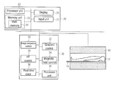
- FIG. 1 shows the procedure for such a calibration measurement in the prior art.
- a preparation step is carried out on a computer 100 of the MR system, which is operated by a user of the MR system in order to control the MR system.
- the determination of an MR center frequency for adjusting the MR system to a test subject is prepared.
- the maximum of the frequency or the resonance frequency of water, known as the Larmor frequency for the test subject in the MR system is determined. Knowledge of the exact frequency is important, for example, when determining the frequency of an RF pulse that is radiated by the MR system onto the test subject.
- This preliminary or preparation step S 1 includes, inter alia, loading program files into the main memory of the computer, allocating storage space in the program memory, etc.
- step S 1 a After preparing for this calibration step by running the program file that is intended to carry out the frequency calibration, there is a time delay, shown in step S 1 a , before the computer 100 commands the system control computer 200 to carry out the calibration of the frequency. Communication between the computer 100 and the system control computer 200 is necessary for this before the frequency calibration can finally be carried out in step S 2 .
- There is a further time delay S 2 a which is needed to transmit the information to the system control computer and to prepare the measurement itself on the system control computer, until the measurement can finally be initiated in step S 2 .
- step S 2 b the computer is informed in step S 2 that the frequency calibration has been completed.
- the preparation includes loading the respective program sections into the main memory, etc.
- step S 4 there are again time delays for the required communication and preparation, shown by step S 3 b and step S 4 a.
- the computer is again informed of the end of this calibration step and, before a polarization field B 0 can be adjusted to the test subject step S 5 , there are again time delays S 4 b and S 5 a.
- a method for carrying out calibration measurements in an MR system, wherein the calibration measurements are carried out to acquire an MR image of a test subject.
- the MR system has a computer to operate the MR system through a user, and a system control computer, which is designed to control a plurality of system components in the MR system.
- a preparation step is carried out on the computer to prepare a first calibration step, in which the system control computer calibrates a first parameter of a system component to the test subject.
- a second calibration step is prepared, in which a second parameter of a system component is adjusted to a test subject by the system control computer.
- the first calibration step is carried out by the system control computer and the second calibration step is carried out by the system control computer, the preparation step on the computer to prepare a first and second calibration step being completed before one of the calibration steps is initiated by the system control computer.
- the preparation step may be, inter alia, the loading of a program file containing executable commands into a main memory of the computer, the system control computer being prompted to carry out the first calibration step by the commands stored in the program file.
- the preparation step comprises the loading of a second program file containing executable commands into the main memory of the computer, the system control computer being prompted to carry out the second calibration step by the second program file.
- the preparation step may include allocating storage space in the main memory of the computer for the first and second program file and informing the system control computer that the first and the second calibration steps are to be carried out.
- the preparation step may further include placing a receive chain in a receiving unit of the MR system and the setting of possible commands that are issued to a couch control in order to move a couch on which the test subject is arranged.
- the first calibration step may be, for example, an adjustment to a center frequency of an RF transmission unit for radiating the RF pulse into the test subject.
- the second calibration step may include an adjustment of a voltage, the transmitter voltage, with which the RF transmission unit generates the RF pulse that is radiated into the test subject.
- the first calibration step is repeated by the system control computer after the third calibration step, in a fourth calibration step. That is, after the adjustment of the polarization field in the third calibration step, the resonance frequency is again adjusted to the potentially changed polarization field B 0 .
- the preparation step on the computer the preparation of the first to fourth calibration steps is now carried out in a single preparation step, before one of the calibration steps is initiated by the system control computer.
- the first calibration step involving the adjustment of the center frequency may comprise a first partial step with a first fairly rough determination of the center frequency, which is followed by the second calibration step comprising the adjustment of the transmitter voltage. After this adjustment of the transmitter voltage, a second partial step of the first calibration step may ensue, in which there is a more precise determination of the center frequency, which is more precise that the first fairly rough determination.
- the preparation step encompasses in this example the preparation of the first and second partial step and the preparation is completed before one of the calibration steps is initiated by the system control computer.
- all the calibration steps that are necessary before carrying out an MR measurement to acquire an MR image are prepared in a single preparation step, such that all the calibration steps can be carried out after this without the computer having to be involved in the meantime before the end of the calibration step.
- the unplannable time delays that occur for the communication between the computer and system control computer are still only minimal, and all the calibration steps can be carried out one after another with precise time-planning.
- the system control computer can adjust, inter alia, the following system components and parameters: an RF control unit, which radiates the RF pulse into the test subject with a voltage to be adjusted, wherein the RF pulse has a center frequency that is to be adjusted; furthermore, a magnetic field control is provided as a component that minimizes the changes in the polarization field B 0 due to the test subject with the aid of shim coils, for example.
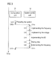
- FIG. 3 shows a time schedule for optimized execution of calibration measurements according to one aspect of the invention.
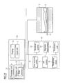
- FIG. 2 shows a black diagram of an MR system with which, as will be explained in detail, calibration measurements can be carried out in a time-optimized manner.
- the MR system has a scanner with a magnet 10 for generating a polarization field B 0 , an examination subject 12 arranged on a bed 11 being moved into the MR scanner or into the magnet 10 in order to acquire data for MR images of a partial area of the examination subject 12 .
- the MR system has a computer 20 , with which an operator can operate and control the MR system.
- the computer 20 has an input unit (interface) 21 , via which the operator can make inputs, such as, for example, the selection of imaging sequences or the positioning of slices.
- a processor 22 is provided for control of the computer.
- a magnetic field control 34 is responsible for the homogeneity of the polarization field B 0 and in this magnetic field control shim currents are calculated in shim coils, which are not shown, and applied, with the magnetic fields generated by the shim coils compensating for magnetic field inhomogeneities in the polarization field B 0 .
- a processor unit 35 controls the procedure in the system control computer 30 .
- the system control computer further has a real-time clock 36 , with which the exact sequence of the RF pulses and magnetic field gradients can be established with microsecond precision, and which can be used by the processor unit 35 to control the various units 31 - 34 .
- the MR system shown in FIG. 2 has further components are not included in FIG. 2 for clarity, and that are not significant for understanding the invention.
- the MR system has gradient coils to generate the magnetic field gradients and likewise RF coils to transmit the RF pulses and also to detect the MR signals.
- the functional units shown in FIG. 2 do not have to be implemented with the separation into different units that is shown. Some of the functional units may be combined in one unit.
- the units shown in FIG. 2 can be implemented using hardware, software or a combination of hardware and software.
- a step S 50 the preparations for the individual calibration steps then ensue again on the computer, the adaptation of the transmitter voltage and the adaptation of the B 0 field being achieved as in FIG. 3 and being denoted by the same reference signs as with S 43 or S 44 .
- a fairly coarse frequency determination can be carried out after the time intervals S 50 a and S 50 b for the transmission of information to the system control computer in step S 51 , followed in step S 52 by a more precise frequency determination, in which the center frequency is determined more precisely than in step S 51 .
- the waiting time after the adjustment of the B 0 field is again similar to step S 45 and corresponds to this step in this respect, whilst in step S 53 a further adjustment of the center frequency ensures after the adjustment of the B 0 field. Since the frequency determination in step S 52 and S 51 is more precise altogether than in the comparable step S 42 , it is possible that the frequency determination in step S 53 may not necessarily correspond to the frequency determination in step S 46 .
- steps S 54 a and S 54 b the method is terminated by informing the computer that the calibration steps have been completed.
Abstract
Description
- 1. Field of the Invention
- The present invention concerns a method for carrying out calibration measurements in an MR system, as well as an MR system for implementing such a method.
- 2. Description of the Prior Art
- In MR systems, in order to acquire an MR image, the MR signals must be acquired using system parameters such as the resonance frequency, transmitter reference amplitude, or the polarization field B0, have to be adjusted to the test subject in order to be able to obtain meaningful MR images of the test subject. In order to determine the parameters for these system components, a stand-alone calibration step is carried out in each case. This usually involves a specific stand-alone MR measurement and an evaluation provided therefor. Within such an MR measurement, which is carried out in a system control computer, the time schedule can be set and carried out in the sub-microsecond range. This is relevant, for example, when the calibration step is formed by multiple sub-steps that are dependent on one another and, for example, executed in repeated iterations that require a specific time delay between them. Each MR measurement is prepared in a computer, the “host-computer”, and after an unknown and varying time delay, the MR measurement is initiated by the system control computer after the computer has informed the system control computer that and how the measurements are intended to be carried out.
-
FIG. 1 shows the procedure for such a calibration measurement in the prior art. In a step S1, a preparation step is carried out on acomputer 100 of the MR system, which is operated by a user of the MR system in order to control the MR system. In this step, the determination of an MR center frequency for adjusting the MR system to a test subject is prepared. When adjusting the center frequency, the maximum of the frequency or the resonance frequency of water, known as the Larmor frequency for the test subject in the MR system is determined. Knowledge of the exact frequency is important, for example, when determining the frequency of an RF pulse that is radiated by the MR system onto the test subject. This preliminary or preparation step S1 includes, inter alia, loading program files into the main memory of the computer, allocating storage space in the program memory, etc. After preparing for this calibration step by running the program file that is intended to carry out the frequency calibration, there is a time delay, shown in step S1 a, before thecomputer 100 commands thesystem control computer 200 to carry out the calibration of the frequency. Communication between thecomputer 100 and thesystem control computer 200 is necessary for this before the frequency calibration can finally be carried out in step S2. There is a further time delay S2 a, which is needed to transmit the information to the system control computer and to prepare the measurement itself on the system control computer, until the measurement can finally be initiated in step S2. In step S2 b the computer is informed in step S2 that the frequency calibration has been completed. Before thecomputer 100 can carry out the preparation for a further calibration step to adjust the transmitter voltage in step S3, there is a further time delay, labelled as step S3 a. As in step S1, the preparation includes loading the respective program sections into the main memory, etc. Before this calibration of the voltage can be carried out in step S4, there are again time delays for the required communication and preparation, shown by step S3 b and step S4 a. The computer is again informed of the end of this calibration step and, before a polarization field B0 can be adjusted to the test subject step S5, there are again time delays S4 b and S5 a. After the preparation for this adjustment has been completed in step S5, there are time delays S5 b and S6 a, before the B0 field can be adjusted to the test subject in step S6, for example, by switching the currents in shim coils provided for this purpose, which compensate for any magnetic field inhomogeneities so that the polarization field B0 is as homogeneous as possible across the measurement field. After completion of step S6, the time delays S6 b and S7 a are required for communication between thecomputer 100 and thesystem control computer 200. Until the currents in the shim coils have finally stabilized to homogenize the polarization field B0, there is a waiting time in step S7. Following this, after a time delay S8 a in step S8, a further frequency calibration can be prepared, which can again be initiated by the system control computer in step S9 after the time delays S8 b and S9, the time delay in steps S8 b and S9 b again being due to communication betweenunits - The individual preparation phases and time delays that result inter alia from communication between the two units extend the overall time required for the calibration measurements.
- An object of the present invention is to provide a method for carrying out calibration measurements that is accelerated compared to known methods.
- According to a first aspect of the invention, a method is provided for carrying out calibration measurements in an MR system, wherein the calibration measurements are carried out to acquire an MR image of a test subject. The MR system has a computer to operate the MR system through a user, and a system control computer, which is designed to control a plurality of system components in the MR system. According to one step in the method, a preparation step is carried out on the computer to prepare a first calibration step, in which the system control computer calibrates a first parameter of a system component to the test subject. Furthermore, in the preparation step, a second calibration step is prepared, in which a second parameter of a system component is adjusted to a test subject by the system control computer. Finally the first calibration step is carried out by the system control computer and the second calibration step is carried out by the system control computer, the preparation step on the computer to prepare a first and second calibration step being completed before one of the calibration steps is initiated by the system control computer.
- This means that the individual calibration steps are prepared in a single preparation step. This leads to a saving of time since, inter alia, less communication is necessary between the computer and the system control computer. Furthermore, the procedure is easier to plan since less communication is necessary between the computer and the system control computer. The duration of this communication cannot be determined beforehand. Since overall there are fewer steps that have an indefinite duration, the adjustment steps are easier to predict.
- The preparation step may be, inter alia, the loading of a program file containing executable commands into a main memory of the computer, the system control computer being prompted to carry out the first calibration step by the commands stored in the program file. Similarly, the preparation step comprises the loading of a second program file containing executable commands into the main memory of the computer, the system control computer being prompted to carry out the second calibration step by the second program file. Furthermore, the preparation step may include allocating storage space in the main memory of the computer for the first and second program file and informing the system control computer that the first and the second calibration steps are to be carried out. The preparation step may further include placing a receive chain in a receiving unit of the MR system and the setting of possible commands that are issued to a couch control in order to move a couch on which the test subject is arranged.
- The first calibration step may be, for example, an adjustment to a center frequency of an RF transmission unit for radiating the RF pulse into the test subject. The second calibration step may include an adjustment of a voltage, the transmitter voltage, with which the RF transmission unit generates the RF pulse that is radiated into the test subject. By having a calibrated frequency for the RF pulse, it is ensured that the RF pulse radiated is resonant with the magnetization in the test subject and it is established by means of the adjustment of the transmitter voltage, as to which tilt angle is achieved with which voltage amplitude during magnetization in the test subject. In addition, a third calibration step may be carried out by the system control computer, in which the polarization field B0 is adjusted to the test subject such that a change in the polarization field B0 caused by the test subject is minimized. The preparation step carried out in the computer may also include this third calibration step, the preparation step being completed before one of the three calibration steps is initiated by the system control computer.
- The calibration steps are preferably carried out in numerical order, that is, the first calibration step before the second and the second calibration step before the third calibration step. This sequence is sensible, as it is first necessary to check what the resonance frequency is before the transmitter voltage is adjusted. The B0 field optimization can then be carried out.
- It is further possible for the first calibration step to be repeated by the system control computer after the third calibration step, in a fourth calibration step. That is, after the adjustment of the polarization field in the third calibration step, the resonance frequency is again adjusted to the potentially changed polarization field B0. In the preparation step on the computer, the preparation of the first to fourth calibration steps is now carried out in a single preparation step, before one of the calibration steps is initiated by the system control computer.
- As a result of the fact that less time needs to be expended on the calibration, various calibrations can also be combined or entangled with one another. For example, the first calibration step involving the adjustment of the center frequency may comprise a first partial step with a first fairly rough determination of the center frequency, which is followed by the second calibration step comprising the adjustment of the transmitter voltage. After this adjustment of the transmitter voltage, a second partial step of the first calibration step may ensue, in which there is a more precise determination of the center frequency, which is more precise that the first fairly rough determination. The preparation step encompasses in this example the preparation of the first and second partial step and the preparation is completed before one of the calibration steps is initiated by the system control computer.
- Preferably, all the calibration steps that are necessary before carrying out an MR measurement to acquire an MR image are prepared in a single preparation step, such that all the calibration steps can be carried out after this without the computer having to be involved in the meantime before the end of the calibration step.
- The invention further concerns an MR system designed for this purpose, having a system control computer that is designed to control multiple system components of the MR system, and which is designed to adjust a first parameter of a system component of the MR system to the test subject in a first calibration step, with the system control computer adjusting a second parameter of a system component to the test subject in a second calibration step. The computer, with which an operator or user operates the MR system, is designed in this case such that the preparation step for the calibration steps is carried out in the computer before the system control computer initiates one of the calibration steps. The system control computer preferably has a real-time clock, with which the procedure is clocked in most of the system components. As a result thereof, it becomes possible to plan the execution of the calibration measurement precisely in the microsecond range. The unplannable time delays that occur for the communication between the computer and system control computer are still only minimal, and all the calibration steps can be carried out one after another with precise time-planning. The system control computer can adjust, inter alia, the following system components and parameters: an RF control unit, which radiates the RF pulse into the test subject with a voltage to be adjusted, wherein the RF pulse has a center frequency that is to be adjusted; furthermore, a magnetic field control is provided as a component that minimizes the changes in the polarization field B0 due to the test subject with the aid of shim coils, for example.
-
FIG. 1 is a flowchart for carrying out calibration measurements, as known in the prior art. -
FIG. 2 is a block diagram of an MR system with which the execution of calibration measurements according to the invention is optimized. -
FIG. 3 shows a time schedule for optimized execution of calibration measurements according to one aspect of the invention. -
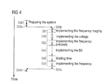
FIG. 4 shows a further flowchart for carrying out calibration measurements according to a further aspect of the invention. -
FIG. 2 shows a black diagram of an MR system with which, as will be explained in detail, calibration measurements can be carried out in a time-optimized manner. The MR system has a scanner with amagnet 10 for generating a polarization field B0, an examination subject 12 arranged on abed 11 being moved into the MR scanner or into themagnet 10 in order to acquire data for MR images of a partial area of theexamination subject 12. The MR system has acomputer 20, with which an operator can operate and control the MR system. Thecomputer 20 has an input unit (interface) 21, via which the operator can make inputs, such as, for example, the selection of imaging sequences or the positioning of slices. Aprocessor 22 is provided for control of the computer. In amemory unit 23 there are, together with pre-stored imaging sequences, program files, which initiate calibration steps in asystem control computer 30 when they are carried out in theprocessor 22. Thememory unit 23 has amain memory 24, which is used by theprocessor unit 22 when in operation to process programs. On adisplay 25, MR images can be displayed, and/or the operator can be informed about operating parameters or operating conditions in the MR system. Thecomputer 20 can also be described as the host computer for the MR system. The MR system further has asystem control computer 30, with which some system components of the MR system are controlled. The system control computer has anRF control 31, in which the generation of the RF pulses that are radiated into the test subject is controlled. The RF control comprises, for example, an RF transmission unit, which is not shown, and an RF generator for generating RF pulses, which is not shown. In addition to theRF control 31, agradient control 32 is provided for the control of the magnetic field gradients that are used for the spatial encoding of the MR signals that have been detected. Animage sequence control 33 controls the sequence of the RF pulses radiated and magnetic field gradients, and thus controls inter alia theRF control 31 and thegradient control 32. Amagnetic field control 34 is responsible for the homogeneity of the polarization field B0 and in this magnetic field control shim currents are calculated in shim coils, which are not shown, and applied, with the magnetic fields generated by the shim coils compensating for magnetic field inhomogeneities in the polarization field B0. Aprocessor unit 35 controls the procedure in thesystem control computer 30. The system control computer further has a real-time clock 36, with which the exact sequence of the RF pulses and magnetic field gradients can be established with microsecond precision, and which can be used by theprocessor unit 35 to control the various units 31-34. - It is known to those skilled in the art how MR signals are generated in different ways by radiating RF pulses and applying magnetic field gradients, how the MR signals are detected, and how MR images are calculated therefrom, so this need not be described in greater detail herein. The MR system shown in
FIG. 2 has further components are not included inFIG. 2 for clarity, and that are not significant for understanding the invention. For example, in themagnet 10, the MR system has gradient coils to generate the magnetic field gradients and likewise RF coils to transmit the RF pulses and also to detect the MR signals. The functional units shown inFIG. 2 do not have to be implemented with the separation into different units that is shown. Some of the functional units may be combined in one unit. Furthermore, the units shown inFIG. 2 can be implemented using hardware, software or a combination of hardware and software. - As explained below, the
computer 20 and thesystem control computer 30 in particular are programmed in order to achieve an optimized execution of calibration measurements before the start of the measurements to acquire MR images. In particular, the preparation of the calibration steps in the computer is carried out in one single preparation step. -
FIG. 3 shows the interaction between thecomputer 20 and thesystem control computer 30. In a step S40, a preparation step is carried out in thecomputer 20. All the calibration steps that are to be carried out later by the system control computer are prepared in this preparation step, for example, allocating storage space in the main memory, loading into the main memory the relevant program files that are necessary to carry out the individual calibration steps, informing the individual system components that a measurement will be initiated soon, etc. In steps S40 a and S41 a, after the end of the preparation step, information is transmitted to system control computer which it needs to carry out all the calibration steps that are necessary before capturing MR data for the MR image. In step S42, the frequency calibration is then carried out, in which a center frequency of the transmission unit is adjusted to the Larmor frequency of the test subject. In step S43 there then ensues the calibration of the voltage, in which the transmitter voltage in theRF control 31 is adjusted to the parameters of the current measurement. In particular a check is carried out here to determine what transmitter voltage is required. In step S44, the B0 field optimization is then carried out by, for example, measuring the inhomogeneities and by determining the currents that are required in the shim coils to compensate for these inhomogeneities. In step S45 there is a predetermined time delay until said B0 field optimization has become established, that is, until the currents in the shim coils have stabilized and are generating a constant balanced magnetic field. After the end of S45, in step S46 there then follows calibration to the center frequency. Since the calibration of the magnetic field in step S45 has a direct impact on the Larmor frequency, the frequency of the transmission pulse that is generated by theRF control 31 is optimized once again in a step S46. Information is subsequently transmitted to the computer in step S47 and S47 b to the effect that the calibration measurements have been completed in full. - If the course of the procedure in
FIG. 3 is compared with that inFIG. 1 , it is evident that it was possible to reduce the time required for the overall time schedule. In particular, far fewer steps are necessary for the communication between the computer and the system control computer. Furthermore, it is possible to set the time schedule precisely in the system control computer since the timing of the individual calibration steps in thesystem control computer 30 can be defined very precisely in the microsecond range. In the embodiment shown inFIG. 3 , any imponderables, such as the unpredictable duration of communication with a computer, are avoided after the start of the calibration steps. It merely remains necessary to wait for the exact time required, for the waiting time in step S45, for example, so that unnecessary waiting times are minimized and a procedure that runs with maximum precision can be guaranteed. - As is shown in
FIG. 4 , it is consequently also possible to interleave the individual calibration steps with one another. For example, it may be advisable to determine the frequencies only coarsely before carrying out the transmitter voltage calibration and to carry out a better, fine calibration of the resonance frequency on the basis of a transmitter voltage calibration that is determined after that. In a step S50, the preparations for the individual calibration steps then ensue again on the computer, the adaptation of the transmitter voltage and the adaptation of the B0 field being achieved as inFIG. 3 and being denoted by the same reference signs as with S43 or S44. Instead of a precise frequency determination, a fairly coarse frequency determination can be carried out after the time intervals S50 a and S50 b for the transmission of information to the system control computer in step S51, followed in step S52 by a more precise frequency determination, in which the center frequency is determined more precisely than in step S51. The waiting time after the adjustment of the B0 field is again similar to step S45 and corresponds to this step in this respect, whilst in step S53 a further adjustment of the center frequency ensures after the adjustment of the B0 field. Since the frequency determination in step S52 and S51 is more precise altogether than in the comparable step S42, it is possible that the frequency determination in step S53 may not necessarily correspond to the frequency determination in step S46. In steps S54 a and S54 b, the method is terminated by informing the computer that the calibration steps have been completed. - In summary, a simpler, time-saving calibration measurement is possible since the unpredictable time intervals that occur in particular during communication between the computer and the system control computer are minimized and now continue to occur only at the start and end of the calibration steps.
- Although modifications and changes may be suggested by those skilled in the art, it is the intention of the inventor to embody within the patent warranted hereon all changes and modifications as reasonably and properly come within the scope of his contribution to the art.
Claims (11)
Applications Claiming Priority (3)
| Application Number | Priority Date | Filing Date | Title |
|---|---|---|---|
| DE102014210417 | 2014-06-03 | ||
| DE102014210417.3A DE102014210417B4 (en) | 2014-06-03 | 2014-06-03 | Improved system adjustment in a MR system |
| DE102014210417.3 | 2014-06-03 |
Publications (2)
| Publication Number | Publication Date |
|---|---|
| US20150346309A1 true US20150346309A1 (en) | 2015-12-03 |
| US10151821B2 US10151821B2 (en) | 2018-12-11 |
Family
ID=54481334
Family Applications (1)
| Application Number | Title | Priority Date | Filing Date |
|---|---|---|---|
| US14/729,538 Active 2037-05-21 US10151821B2 (en) | 2014-06-03 | 2015-06-03 | System calibration in an MR system |
Country Status (2)
| Country | Link |
|---|---|
| US (1) | US10151821B2 (en) |
| DE (1) | DE102014210417B4 (en) |
Cited By (4)
| Publication number | Priority date | Publication date | Assignee | Title |
|---|---|---|---|---|
| US20140347052A1 (en) * | 2012-10-26 | 2014-11-27 | Kabushiki Kaisha Toshiba | Magnetic resonance imaging apparatus and frequency shift measuring method |
| US9606205B1 (en) * | 2016-01-04 | 2017-03-28 | Hitachi, Ltd. | Magnetic resonance imaging apparatus, RF shimming method, and magnetic resonance imaging method |
| US10690742B2 (en) * | 2018-03-29 | 2020-06-23 | General Electric Company | Method and apparatus for calibrating center frequency of MR and MRI system |
| US10705172B2 (en) | 2016-02-24 | 2020-07-07 | Siemens Healthcare Gmbh | Magnetic resonance apparatus and method for dynamic adjustment thereof with multiple adjustment parameters |
Citations (8)
| Publication number | Priority date | Publication date | Assignee | Title |
|---|---|---|---|---|
| US20040246004A1 (en) * | 2003-03-28 | 2004-12-09 | Suss Microtec Test Systems Gmbh | Calibration method for carrying out multiport measurements on semiconductor wafers |
| US7019535B2 (en) * | 2002-09-16 | 2006-03-28 | Agilent Technologies, Inc. | Method and system for calibrating a measurement device path and for measuring a device under test in the calibrated measurement device path |
| US20070041511A1 (en) * | 2005-01-27 | 2007-02-22 | Kan Tan | Apparatus and method for processing a signal under test for measuring the impedance of a device under test |
| US20070276614A1 (en) * | 2006-05-25 | 2007-11-29 | Kan Tan | De-embed method for multiple probes coupled to a device under test |
| US20080004819A1 (en) * | 2004-05-14 | 2008-01-03 | Matsushita Electric Industrial Co., Ltd. | Method and Apparatus for Measuring Electric Circuit Parameters |
| US20170060150A1 (en) * | 2015-08-26 | 2017-03-02 | Google Inc. | Thermostat with multiple sensing systems integrated therein |
| US20180036740A1 (en) * | 2016-08-08 | 2018-02-08 | Bradley Nelson | Ion plasma disintegrator |
| US20180059176A1 (en) * | 2016-08-26 | 2018-03-01 | Delta Design, Inc. | Offline vision assist method and apparatus for integrated circuit device vision alignment |
Family Cites Families (1)
| Publication number | Priority date | Publication date | Assignee | Title |
|---|---|---|---|---|
| US9041396B2 (en) | 2012-01-23 | 2015-05-26 | Siemens Aktiengesellschaft | Dynamic B0 field detection by magnetic resonance navigators, and correction for multichannel reception and/or transmission RF coil configurations |
-
2014
- 2014-06-03 DE DE102014210417.3A patent/DE102014210417B4/en active Active
-
2015
- 2015-06-03 US US14/729,538 patent/US10151821B2/en active Active
Patent Citations (8)
| Publication number | Priority date | Publication date | Assignee | Title |
|---|---|---|---|---|
| US7019535B2 (en) * | 2002-09-16 | 2006-03-28 | Agilent Technologies, Inc. | Method and system for calibrating a measurement device path and for measuring a device under test in the calibrated measurement device path |
| US20040246004A1 (en) * | 2003-03-28 | 2004-12-09 | Suss Microtec Test Systems Gmbh | Calibration method for carrying out multiport measurements on semiconductor wafers |
| US20080004819A1 (en) * | 2004-05-14 | 2008-01-03 | Matsushita Electric Industrial Co., Ltd. | Method and Apparatus for Measuring Electric Circuit Parameters |
| US20070041511A1 (en) * | 2005-01-27 | 2007-02-22 | Kan Tan | Apparatus and method for processing a signal under test for measuring the impedance of a device under test |
| US20070276614A1 (en) * | 2006-05-25 | 2007-11-29 | Kan Tan | De-embed method for multiple probes coupled to a device under test |
| US20170060150A1 (en) * | 2015-08-26 | 2017-03-02 | Google Inc. | Thermostat with multiple sensing systems integrated therein |
| US20180036740A1 (en) * | 2016-08-08 | 2018-02-08 | Bradley Nelson | Ion plasma disintegrator |
| US20180059176A1 (en) * | 2016-08-26 | 2018-03-01 | Delta Design, Inc. | Offline vision assist method and apparatus for integrated circuit device vision alignment |
Cited By (5)
| Publication number | Priority date | Publication date | Assignee | Title |
|---|---|---|---|---|
| US20140347052A1 (en) * | 2012-10-26 | 2014-11-27 | Kabushiki Kaisha Toshiba | Magnetic resonance imaging apparatus and frequency shift measuring method |
| US9869742B2 (en) * | 2012-10-26 | 2018-01-16 | Toshiba Medical Systems Corporation | Magnetic resonance imaging apparatus and frequency shift measuring method |
| US9606205B1 (en) * | 2016-01-04 | 2017-03-28 | Hitachi, Ltd. | Magnetic resonance imaging apparatus, RF shimming method, and magnetic resonance imaging method |
| US10705172B2 (en) | 2016-02-24 | 2020-07-07 | Siemens Healthcare Gmbh | Magnetic resonance apparatus and method for dynamic adjustment thereof with multiple adjustment parameters |
| US10690742B2 (en) * | 2018-03-29 | 2020-06-23 | General Electric Company | Method and apparatus for calibrating center frequency of MR and MRI system |
Also Published As
| Publication number | Publication date |
|---|---|
| DE102014210417B4 (en) | 2018-03-22 |
| DE102014210417A1 (en) | 2015-12-03 |
| US10151821B2 (en) | 2018-12-11 |
Similar Documents
| Publication | Publication Date | Title |
|---|---|---|
| US10241175B2 (en) | Medical imaging apparatus having multiple subsystems, and operating method therefor | |
| US10101425B2 (en) | Medical imaging apparatus having multiple subsystems, and operating method therefor | |
| US20050189940A1 (en) | Magnetic resonance system and operating method for RF pulse optimization | |
| US10191131B2 (en) | Medical imaging apparatus having multiple subsystems, and operating method therefor | |
| JP6320357B2 (en) | Operation of a medical imaging inspection device including multiple subsystems | |
| US10151821B2 (en) | System calibration in an MR system | |
| US9846213B2 (en) | Optimization of the noise development of a 3D gradient echo sequence in a magnetic resonance system | |
| US10162033B2 (en) | Magnetic resonance imaging method and apparatus | |
| KR101718105B1 (en) | Controlling a magnetic resonance system | |
| US10185007B2 (en) | Noise reduction during selective MR excitation | |
| US10473743B2 (en) | Method and magnetic resonance apparatus for determining a scan sequence based on a representation of a pulse response in k-space of the gradient system | |
| US10156622B2 (en) | Method and apparatus for sectional optimization of radial MR pulse sequences | |
| US10288709B2 (en) | Medical imaging examination apparatus having multiple sub-systems and method for the operation thereof | |
| US20180031652A1 (en) | Magnetic resonance imaging apparatus and method with slice-specific adjustment of radio frequency pulses to current ambient conditions | |
| US10061001B2 (en) | Method and medical imaging apparatus of determining time windows in a scan sequence | |
| US10267885B2 (en) | Method and apparatus for magnetic resonance imaging | |
| US10527697B2 (en) | Method and imaging apparatus for optimizing a signal-to-noise ratio of a magnetic resonance image | |
| US9500733B2 (en) | Method and apparatus for obtaining main magnetic field information and radio pulse related information in a magnetic resonance imaging system with different flip angles | |
| US20150219733A1 (en) | RF Pulse Alignment | |
| US10281546B2 (en) | Method and apparatus for optimizing a magnetic resonance control sequence | |
| US10823811B2 (en) | Method and magnetic resonance apparatus for calibrating a control sequence for examination of an object | |
| US20150268318A1 (en) | Method and magnetic resonance system for fat saturation | |
| US20170153308A1 (en) | Method and apparatus for magnetic resonance imaging | |
| KR20130111445A (en) | Control of a magnetic resonance system | |
| US20220381864A1 (en) | Breathing and motion monitoring method for mri system, mri system and method, and storage medium |
Legal Events
| Date | Code | Title | Description |
|---|---|---|---|
| AS | Assignment |
Owner name: SIEMENS AKTIENGESELLSCHAFT, GERMANY Free format text: ASSIGNMENT OF ASSIGNORS INTEREST;ASSIGNORS:CAMPAGNA, SWEN;WULLENWEBER, MICHAEL;SIGNING DATES FROM 20150907 TO 20150917;REEL/FRAME:036746/0924 |
|
| STCF | Information on status: patent grant |
Free format text: PATENTED CASE |
|
| AS | Assignment |
Owner name: SIEMENS HEALTHCARE GMBH, GERMANY Free format text: ASSIGNMENT OF ASSIGNORS INTEREST;ASSIGNOR:SIEMENS AKTIENGESELLSCHAFT;REEL/FRAME:049155/0949 Effective date: 20190424 |
|
| MAFP | Maintenance fee payment |
Free format text: PAYMENT OF MAINTENANCE FEE, 4TH YEAR, LARGE ENTITY (ORIGINAL EVENT CODE: M1551); ENTITY STATUS OF PATENT OWNER: LARGE ENTITY Year of fee payment: 4 |
|
| AS | Assignment |
Owner name: SIEMENS HEALTHINEERS AG, GERMANY Free format text: ASSIGNMENT OF ASSIGNORS INTEREST;ASSIGNOR:SIEMENS HEALTHCARE GMBH;REEL/FRAME:066088/0256 Effective date: 20231219 |