US2430640A - Induction heating system with alternately energized coaxial conductors - Google Patents
Induction heating system with alternately energized coaxial conductors Download PDFInfo
- Publication number
- US2430640A US2430640A US596829A US59682945A US2430640A US 2430640 A US2430640 A US 2430640A US 596829 A US596829 A US 596829A US 59682945 A US59682945 A US 59682945A US 2430640 A US2430640 A US 2430640A
- Authority
- US
- United States
- Prior art keywords
- current
- coils
- circuits
- conductor
- valves
- Prior art date
- Legal status (The legal status is an assumption and is not a legal conclusion. Google has not performed a legal analysis and makes no representation as to the accuracy of the status listed.)
- Expired - Lifetime
Links
Images

Classifications
-
- H—ELECTRICITY
- H02—GENERATION; CONVERSION OR DISTRIBUTION OF ELECTRIC POWER
- H02M—APPARATUS FOR CONVERSION BETWEEN AC AND AC, BETWEEN AC AND DC, OR BETWEEN DC AND DC, AND FOR USE WITH MAINS OR SIMILAR POWER SUPPLY SYSTEMS; CONVERSION OF DC OR AC INPUT POWER INTO SURGE OUTPUT POWER; CONTROL OR REGULATION THEREOF
- H02M5/00—Conversion of ac power input into ac power output, e.g. for change of voltage, for change of frequency, for change of number of phases
- H02M5/005—Conversion of ac power input into ac power output, e.g. for change of voltage, for change of frequency, for change of number of phases using discharge tubes
Definitions
- This invention relates in general to improvements in electric heating systems, and more particularly to means for supplying heating current to an electrically conductive object by induction through a converting system comprising a plurality of alternately operating circuits.
- Induction heating systems supplied from a source of direc current or of low frequency alternating current often utilize a converting system in which current is transmitted through a plurality of alternately operating circuits as a result of the control of the flow of current by
- the circuits may be severally connected to different sections of the heating inductor which are bridged by a capacitor for supplying the magnetizing component of the inductor exciting current and also the commutating current for the valves.
- the coupling of the valve circuits with each other and with any circuit to which the commutating capacitor may be connected should be as close as possible to unity. Stated otherwise, the leakage reactance of each circuit with respect to the others shouldbe as low as practicable.
- the commutating capacitor being connected with an induced coil of the inductor operating at a relatively low voltage.
- the inducing coils then carry only the load component of the inductor current and may therefore have a relatively small cross section.
- the leakage reactances of the coils are made relatively low by arranging these different coils to be coextensive in their length. Further reduction of the leakage reactances may be obtained by building the alternately operating inducing coils from coaxial conductors and also by forming the induced coil of ahollow conductor surrounding the coaxial inducing coils. The induced coil then also shields the high voltage inducing coils and prevents accidental contact of the operator therewith.
- Another object of the present invention is to provide a heating system to which current is supplied through a plurality of inductor coils and in which the coupling between the different inductor coils is close to unity.
- Another object of the present invention is to.
- Another object of the present invention is to provide a heating system in which the load component of the exciting current is conductively supplied to an inducing coil and the magnetizing and commutating current components are supplied by a capacitor inductively connected with the inducing coil.
- Coils i2, I! are adapted to be placed in inductive relation with an electrically conductive object to be heated by induction of heating currents therein such as a mass of metal contained within a crucible i6.
- onverter ll may be of any known typecomprising a pair of alternately operating output circuits including electric valves for converting currents from circuit l4 into current impulses and comprises a transformer I! having a primary winding l8 divided into a plurality of phase portions severally connected with the different conductors of circuit M.
- the secondary winding IQ of transformer i1 is divided into a plurality of phase portions defining a neutral point and so arranged as to preclude dissymmetrical magnetization of the core upon flow of unidirectional currents in sequence through the different winding portions.
- Each terminal of winding i9 is connected with coils
- the different terminals of winding I! are connected with circuit 2
- the valves are preferably of the discontinuously controllable mercury vapor type of size and design appropriate for the operation thereof in connection with inductors i2, i3.
- the anodes 21 of valves 25 may be assembled with the associated cathodes in separate casings, or the different anodes may be arranged in a common casing provided with a common cathode 28.
- Each anode 21 of valves 26 may likewise be assembled with the associated cathode in a separate casing, or the anodes may be arranged in a common casing provided with a common cathode 30.
- the cathodes are provided with the usual means (not shown) for initiating and maintaining the emission of electrons thereat,
- valves 25, 26 may be controlled by means of suitable control electrodes 3
- , 32 may be energized from circuits 2 22 through a phase shifting circuit comprising a capacitor 33 and a resistor 34 associated with a transformer 36 and current limiting resistors 31, 38.
- the grid circuits may also include sources of negative unidirectional potential conventionally represented as batteries 39, 4D.
- 2, i3 are in inductive relation with a secondary coil 4
- each valve is rendered conductive by the associated grid before the flow of current through the other valve has ceased.
- Two valves are thus momentarily caused to operate in parallel while the total current intensity throughthe' valves is prevented from varying rapidly by reactor 23.
- Capacitor 42 then supplies to circuits 2
- circuits 2 i, 22 are supplied with current of constant frequency and substantially uniform intensity, This current flows in coils
- Capacitor 42 is inductively coupled with circuits 2
- the commutating current should be supplied to circuits 2 I, 22 from capacitor 42 through connections having a low resistance and a low inductive reactance.
- should therefore be made close to unity, which means that the leakage reactance of each coil with respect to the others should be made as low as practicable. While the coils have been shown axially juxtaposed in Fig. 1 to clarify the drawing, they should be at least coextensive in length to meet the bove mentioned conditions.
- coil I2 consists of a helically wound elongated conductor and coil H of a hollow conductor surrounding conductor i2 coaxially therewith and separated therefrom by suitable insulation 43.
- consists of a hollow conductor surrounding conductor i3 coaxially therewith and separated therefrom by suitable insulation 44.
- may be provided with means for causing a flow of cooling fluid such as water or oil therethrough and around conductor ii.
- may be provided with a suitable nipple 45 to be connected with a source of cooling fluid and insulation 44 is so shaped as to define passages for the flow of cooling fluid.
- insulation 44 may consist of a series of spacers permitting direct contact between the cooling fluid and conductors l3, 4
- must be sealed by an insulating washer 46 or equivalent means.
- the different conductors are provided with suitable terminals for the connection thereof with the circuits of the system.
- the three coils have the same number of turns so that the voltage impressed on capacitor 42 is equal to one-half the voltage between the non-common conductors of circuits 2
- the coils may be so arranged as to present the conductor cross section shown in Fig. 8.
- is a tube of sufficient diameter'to contain side by side a plurality of pairs of coaxially disposed conductors which are connected in series to form coils I 2 and ii.
- Conductor i3 is then coated with a continuous layer of insulation 41 for the reason that the dverent ad iacent sections of conductor ll are at diiferent potentials. Cooling'fluid may be caused to flow in the spaces between conductor 4i and insulation 41.
- conductors II, II or conductor I may be interrupted at least at one intermediate point of the coil to define a plurality of sections which are connected in parallel.
- Fig. 4 shows conductor 4i interrupted at least at onepoint to form a plurality of sections. The sections are connected electrically in parallel by means of a pair of longitudinal conductors 48, 49 which are connected to the ends of the sections.
- Conductors I, 49 may consist of pipe sections connected of fluid through the diiierent sections of conductor 4
- conductors i2, i3 consist of a plurality of pairs of coaxially disposed inner and outer conductor sections, each pair being wound to form a single flat or helical turn or! a coil comprising a plurality of adjacent turns.
- Coil li likewise consists of a plurality of hollow conductor sections severally surrounding the pairs of conductor sections of coils i2, i3.
- the sections of conductor I may be connected in series, in series parallel or in parallel. As shown in Fig. 5, pipes 48, 49 connect the sections 01' conductor 4
- coil ii is wound inside of the coil formed by the coaxial combinationof conductors i2, I! so that both coils are coextensive in length and have a low leakage reactance.
- the conductor of coils i2, I are wound in interleaved layers about coil 4i and all three coils are coextensive in length and have a low leakage reactance.
- the cooling of the conductors of the embodiments illustrated in Figs. 7 and 8 may be eflected in any known manner.
- inductors illustrated in Figs. 3 to '7 are shown as cylindrical coils, it will be apparent that inductors embodying the features of such coils may be made of any shape required for the proper induction of heating current within th object to be heated, and may even consist of straight conductor sections in some instances.
- the heating system diagrammatically illustrated in Fig. 2 differs mainly from a system illustrated in Fig. 1 in that separate pairs of alternately operating circuits are associated with each phase portion of winding I 9 and connected between the terminals of winding is and the anodes of the associated valves.
- Each pair of circuits comprises a pair of inductor coils. the diflerent inductor coils being inductively related with coil 4i byarranging the conductors of the diiferent coils as shown in Fig. 8, for example.
- a current converting system comprising a pair of circuits for converting current from said source into current impulses alternately supplied to said circuits, and an inductor for inducing heating current in said object comprising a pair of coaxially disposed conductors severally connected with said circuits to alternately receive exciting current therefrom.
- a sourceof electric current for heating an electrically conductive object by induction of current therein comprising. a sourceof electric current for heating an electrically conductive object by induction of current therein, thecombination of a current converting system comprising a pair of circuits for converting current from said source into current impulses alternately supplied to said circuits, and an inductor for inducing heating current in said object comprising a conductor connected with one of said circuits and wound as a coil and a second conductor connected with the other of said circuits and wound as a second coil substantially coextensive with the first said coil.
- a current converting'system comprising a pair of circuits for converting current from said source into current impulses alternately supplied to said circuits, and an inductor for inducing heating current in said object comprising a pair of coils severally connected with said circuits to alternately receive exciting current therefrom, a winding in inductive relation with said coils, and a capacitor connected with said winding for supplying the magnetizing component of said exciting current.
- a current converting system comprising a pair of circuits for converting current from said source, into current impulses alternately supplied to said circuits, and an inductor for inducing heating current in said object comprising a pair of substantially coextensive coils severally connected with said circuits to alternately receive exciting current therefrom, a winding substantially coextensive with said coils in inductive relation thereto, and a capacitor connected with said winding for supplying the magnetizing component of said exciting current.
- a current converting system comprising a pair of circuits for converting current from said source into current impulses alternately supplied to said circuits, and an inductor for inducing heating current in said object comprising a pair of coaxially disposed conductors severally connected with said circuits to alternately receive exciting current therefrom, a third conductor coaxially disposed with respect to said pair of conductors, and a capacitor connected with said third conductor for supplying the magnetizing component of said exciting current.
- a current converting system comprising a pair of electric valves connected with said source for converting current from said source into current impulses, an inductor for inducing heating current in said object comprising a pair of coils severally connected with said valves to receive exciting current therefrom, a winding in inductive relation with said coils, and a capacitor connected with said winding for supplying the magnetizing component of said exciting current and for supplying commutating current to said valves.
- a current converting system comprising a pair of electric valves connected with said source for converting current from said source into current impulses, an inductor for inducing heating current in said object comprising a pair of substantially coextensive coils severally connected with said valves to alternately receive exciting current therefrom, a winding substantially coextensive with said coils in inductive relation thereto, and a capacitor connected with said winding for supplying the magnetizing component of said exciting current and for supplying commutating current to said valves.
- a current converting system comprising a pair of electric valves connected with said source for converting current from said source into current impulses, an inductor ior inducing heating current in said object comprising a pair of coaxially disposed conductors severally connected with said valves to alternately receive exciting current therefrom, a third conductor coaxiaily disposed with respect to said pair oi conductors, and a capacitor connected with said third conductor for supplying the magnetizing component of said exciting current and for supplying commutating current to said valves.
- a. current converting system comprising a pair 01' electric valves connected with said source for converting current from said source into current impulses, an inductor for inducing heating current in said object comprising a pair of coils severally connected with said valves to receive exciting current therefrom, a winding in inductive relation with said coils, a capacitor connected wth said winding for supplying the magnetizing component of said exciting current and for supplying commutating current to said valves, and means for controlling the conductivity of said valves comprising control electrodes of said valves and connections between said control electrodes and said winding.
Description
Nov. 11, 1947. JOHNSQN 2,430,640
INDUCTION HEATING SYSTEM WITH ALTERNATELY ENERGIZED COAXIAL CONDUCTORS Filed May 31, 1945 2 Sheets-Sheet l imam, 2:. QQWQM NOV 11, 1947. JOHNSON 2,430,646
INDUCTION HEATING SYSTEM WITH ALTERNATELY ENERGIZED COAXIAL CONDUCTORS Filed May 31, 1945 2 Sheets-Sheet 2 means of electric valves.
Patented Nov. 11, 1947 INDUCTION HEATING SYSTEM WITH ALTERNATELY ENERGIZED COAXIAL CONDUCTORS Lauren L. Johnson, La Grange, 11]., asslgnor to Allis-Chalmers Manufacturing Company, Milwaukee, Wis., a corporation of Delaware Application May 31, 1945, Serial No. 596,829
9 Claims.
This invention relates in general to improvements in electric heating systems, and more particularly to means for supplying heating current to an electrically conductive object by induction through a converting system comprising a plurality of alternately operating circuits.
Induction heating systems supplied from a source of direc current or of low frequency alternating current often utilize a converting system in which current is transmitted through a plurality of alternately operating circuits as a result of the control of the flow of current by The circuits may be severally connected to different sections of the heating inductor which are bridged by a capacitor for supplying the magnetizing component of the inductor exciting current and also the commutating current for the valves. In such systems it is generally desirable from the point of view of economy to cause the converter to supply current at a voltage of the order of magnitude of at least 1000 volts, while the cost of capacitors per rated kv.-a. is lowest for voltages of the order of magnitude of a few hundred volts. In addition, to facilitate commutation between the valves of the converter, the coupling of the valve circuits with each other and with any circuit to which the commutating capacitor may be connected should be as close as possible to unity. Stated otherwise, the leakage reactance of each circuit with respect to the others shouldbe as low as practicable.
It is therefore advantageous to energize the alternating operating circuits of the converter at relatively high voltage and to connect them with separate inducing coils of the heating inductor, the commutating capacitor being connected with an induced coil of the inductor operating at a relatively low voltage. The inducing coils then carry only the load component of the inductor current and may therefore have a relatively small cross section. The leakage reactances of the coils are made relatively low by arranging these different coils to be coextensive in their length. Further reduction of the leakage reactances may be obtained by building the alternately operating inducing coils from coaxial conductors and also by forming the induced coil of ahollow conductor surrounding the coaxial inducing coils. The induced coil then also shields the high voltage inducing coils and prevents accidental contact of the operator therewith.
It is therefore an object of the present invention to provide a heating system in which the 'loadcomponent of the exciting current is supplied to an inductor at one voltage and the magnetiz- 1 ing component is supplied at another voltage.
Another object of the present invention is to provide a heating system to which current is supplied through a plurality of inductor coils and in which the coupling between the different inductor coils is close to unity.
Another object of the present invention is to.
provide a heating system in which a high voltage inductor coil is shielded by a low voltage coil in inductive relation therewith.
Another object of the present invention is to provide a heating system in which the load component of the exciting current is conductively supplied to an inducing coil and the magnetizing and commutating current components are supplied by a capacitor inductively connected with the inducing coil.
Objects and advantages other than those above set forth will be apparent from the following different embodiments of inductors comprising generator (not shown) operating at a relatively low frequency. Coils i2, I! are adapted to be placed in inductive relation with an electrically conductive object to be heated by induction of heating currents therein such as a mass of metal contained within a crucible i6.
onverter ll may be of any known typecomprising a pair of alternately operating output circuits including electric valves for converting currents from circuit l4 into current impulses and comprises a transformer I! having a primary winding l8 divided into a plurality of phase portions severally connected with the different conductors of circuit M. The secondary winding IQ of transformer i1 is divided into a plurality of phase portions defining a neutral point and so arranged as to preclude dissymmetrical magnetization of the core upon flow of unidirectional currents in sequence through the different winding portions.
Each terminal of winding i9 is connected with coils |2, |3 through a pair of alternately operating circuits 2|, 22 having a common conductor connected with the neutral point of winding is through an inductive reactor 23. The different terminals of winding I! are connected with circuit 2| through a plurality of electric valves 25 and with circuit 22 through a second plurality of electric valves 26. The valves are preferably of the discontinuously controllable mercury vapor type of size and design appropriate for the operation thereof in connection with inductors i2, i3. The anodes 21 of valves 25 may be assembled with the associated cathodes in separate casings, or the different anodes may be arranged in a common casing provided with a common cathode 28. Each anode 21 of valves 26 may likewise be assembled with the associated cathode in a separate casing, or the anodes may be arranged in a common casing provided with a common cathode 30. The cathodes are provided with the usual means (not shown) for initiating and maintaining the emission of electrons thereat,
The conductivity of valves 25, 26 may be controlled by means of suitable control electrodes 3|, 32 which may be grids when the continuously emissive type of cathode is provided. Grids 3|, 32 may be energized from circuits 2 22 through a phase shifting circuit comprising a capacitor 33 and a resistor 34 associated with a transformer 36 and current limiting resistors 31, 38. The grid circuits may also include sources of negative unidirectional potential conventionally represented as batteries 39, 4D. Coils |2, i3 are in inductive relation with a secondary coil 4| connected with a capacitor 42.
The system being connected as illustrated in Fig. 1, batteries 39, 40 maintain valves 25, 26 nonconductive even when circuit [4 is energized. The action of batteries 39, 40 may be momentarily overcome and at the same time oscillations may be caused to appear in circuits 2|, 22 in any known manner to place the system in normal operation. In the course of such normal operation, the different phase portions of winding I9 supply current in sequence to circuits 2|, 22 through valves 25, 26. While a particular phase portion of winding i9 is carrying current, the valves connected therewith are rendered alternately conductive and nonconductive by the alternating potential component impressed on the grids thereof from transformer 36. The flow of current from transformer I9 is thereby caused to alternate between the path comprising one of valves 25, circuit 2| and coil 2 and the path comprising one of valves 26, circuit 22 and coil i3.
As a result of the connection of transformer 26 with circuits 2|, 22 through a phase shifting circuit, each valve is rendered conductive by the associated grid before the flow of current through the other valve has ceased. Two valves are thus momentarily caused to operate in parallel while the total current intensity throughthe' valves is prevented from varying rapidly by reactor 23. Capacitor 42 then supplies to circuits 2|, 22 a commutating current component which causes the current in the outgoing valve to'drop momentarily to zero, so that the outgoing valve'may be rendered nonconductive by the action of the potential impressed on the grid thereof.
The same operation is repeated sequentially with respect to the different phase portions of winding 9 during each cycle of the voltage of circuit M to cause circuits 2 i, 22 to be supplied with current of constant frequency and substantially uniform intensity, This current flows in coils |2, I3 and induces heating current in the charge contained within crucible IE or in any other electrically conductive object inductively associated with the coils. Capacitor 42 is inductively coupled with circuits 2|, 22 through coils |2, I3 and 4| to impart to circuit 2 i, 22 a capacitive character. The capacitor thus supplies the magnetizing component of the inductor current, and circuits 2|, 22 only supply the load component utilized for the production of heat in the charge, which load component is relatively small compared to the magnetizing component,
To facilitate the commutation process, the commutating current should be supplied to circuits 2 I, 22 from capacitor 42 through connections having a low resistance and a low inductive reactance. The coupling between coils |2, |3, 4| should therefore be made close to unity, which means that the leakage reactance of each coil with respect to the others should be made as low as practicable. While the coils have been shown axially juxtaposed in Fig. 1 to clarify the drawing, they should be at least coextensive in length to meet the bove mentioned conditions.
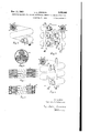
In the embodiment of inductor shown in Fig. 3, coil I2 consists of a helically wound elongated conductor and coil H of a hollow conductor surrounding conductor i2 coaxially therewith and separated therefrom by suitable insulation 43. Coil 4| consists of a hollow conductor surrounding conductor i3 coaxially therewith and separated therefrom by suitable insulation 44. Conductor 4| may be provided with means for causing a flow of cooling fluid such as water or oil therethrough and around conductor ii. For this purpose, conductor 4| may be provided with a suitable nipple 45 to be connected with a source of cooling fluid and insulation 44 is so shaped as to define passages for the flow of cooling fluid.
If the fluid is not substantially conducting, insulation 44 may consist of a series of spacers permitting direct contact between the cooling fluid and conductors l3, 4|. Each end of conductor 4| must be sealed by an insulating washer 46 or equivalent means. The different conductors are provided with suitable terminals for the connection thereof with the circuits of the system. As a result of the coaxial arrangement of coils |2, |3, 4|, the three coils are coextensive in all directions and the inductive relation thereof is assured while their leakage reactances are a minimum.
In the inductor illustrated in Fig. 3, the three coils have the same number of turns so that the voltage impressed on capacitor 42 is equal to one-half the voltage between the non-common conductors of circuits 2|, 22. To further decrease the voltage of the capacitor the coils may be so arranged as to present the conductor cross section shown in Fig. 8. In the latter figure conductor 4| is a tube of sufficient diameter'to contain side by side a plurality of pairs of coaxially disposed conductors which are connected in series to form coils I 2 and ii. Conductor i3 is then coated with a continuous layer of insulation 41 for the reason that the diilerent ad iacent sections of conductor ll are at diiferent potentials. Cooling'fluid may be caused to flow in the spaces between conductor 4i and insulation 41. s
As an alternative arrangement either conductors II, II or conductor I may be interrupted at least at one intermediate point of the coil to define a plurality of sections which are connected in parallel. Fig. 4 shows conductor 4i interrupted at least at onepoint to form a plurality of sections. The sections are connected electrically in parallel by means of a pair of longitudinal conductors 48, 49 which are connected to the ends of the sections. Conductors I, 49 may consist of pipe sections connected of fluid through the diiierent sections of conductor 4| in parallel.
In the embodiment illustrated in Fig. 5v conductors i2, i3 consist of a plurality of pairs of coaxially disposed inner and outer conductor sections, each pair being wound to form a single flat or helical turn or! a coil comprising a plurality of adjacent turns. Coil li likewise consists of a plurality of hollow conductor sections severally surrounding the pairs of conductor sections of coils i2, i3. Adjacent sections of coils l2, it are interconnected by means of Jumpers I, each inner conductor of each section being preferably connected in series with the outer conductors of the adjacent sections and each outer conductor of each section being connected in series with the inner conductors of the adjacent sections so as to equalize the leakage reactances of coils i2, i3. All the inner coil sections may also be connected in series, the outer coil sections then being likewise connected in series. The sections of conductor I may be connected in series, in series parallel or in parallel. As shown in Fig. 5, pipes 48, 49 connect the sections 01' conductor 4| electrically in parallel and conduct cooling fluid to the different sections also in parallel. I
In the embodiment illustrated in Fig. 6, coil ii is wound inside of the coil formed by the coaxial combinationof conductors i2, I! so that both coils are coextensive in length and have a low leakage reactance.
In the embodiment illustrated in Fig. 7, the conductor of coils i2, I: are wound in interleaved layers about coil 4i and all three coils are coextensive in length and have a low leakage reactance. The cooling of the conductors of the embodiments illustrated in Figs. 7 and 8 may be eflected in any known manner.
Although all the inductors illustrated in Figs. 3 to '7 are shown as cylindrical coils, it will be apparent that inductors embodying the features of such coils may be made of any shape required for the proper induction of heating current within th object to be heated, and may even consist of straight conductor sections in some instances.
The heating system diagrammatically illustrated in Fig. 2 differs mainly from a system illustrated in Fig. 1 in that separate pairs of alternately operating circuits are associated with each phase portion of winding I 9 and connected between the terminals of winding is and the anodes of the associated valves. Each pair of circuits comprises a pair of inductor coils. the diflerent inductor coils being inductively related with coil 4i byarranging the conductors of the diiferent coils as shown in Fig. 8, for example.
Cathodes It, 3| are directly interconnected so that the grid circuits require only a single-source of unidirectional potential component represented as a battery 62. The operation of the system illustrated in Fig. 2 is. entirelysimilar to that o! the system illustrated in Fig. 1. z
Although but a few embodiments'of the present invention have been illustrated and described,
Johnson, 8. N. 596,830, filed May 31, 1945.
It is claimed and desired to Patent:
1. In a system comprising a source of electric current for heating an electrically conductive object by induction of current therein, the combination of a current converting system comprising a pair of circuits for converting current from said source into current impulses alternately supplied to said circuits, and an inductor for inducing heating current in said object comprising a pair of coaxially disposed conductors severally connected with said circuits to alternately receive exciting current therefrom.
2. Ina system comprising. a sourceof electric current for heating an electrically conductive object by induction of current therein, thecombination of a current converting system comprising a pair of circuits for converting current from said source into current impulses alternately supplied to said circuits, and an inductor for inducing heating current in said object comprising a conductor connected with one of said circuits and wound as a coil and a second conductor connected with the other of said circuits and wound as a second coil substantially coextensive with the first said coil. 1
3. In a system comprising a source-of electric current for heating an electrically conductive object by induction of current therein, the combination of a current converting'system comprising a pair of circuits for converting current from said source into current impulses alternately supplied to said circuits, and an inductor for inducing heating current in said object comprising a pair of coils severally connected with said circuits to alternately receive exciting current therefrom, a winding in inductive relation with said coils, and a capacitor connected with said winding for supplying the magnetizing component of said exciting current.
4. In a system comprising a source of electric current for heating an electrically conductive object by induction of current therein, the combination of a current converting system comprising a pair of circuits for converting current from said source, into current impulses alternately supplied to said circuits, and an inductor for inducing heating current in said object comprising a pair of substantially coextensive coils severally connected with said circuits to alternately receive exciting current therefrom, a winding substantially coextensive with said coils in inductive relation thereto, and a capacitor connected with said winding for supplying the magnetizing component of said exciting current.
5. In a system comprising a source of electric secure by Letters current for heating an electrically conductive obiect by induction of current therein, the combination of a current converting system comprising a pair of circuits for converting current from said source into current impulses alternately supplied to said circuits, and an inductor for inducing heating current in said object comprising a pair of coaxially disposed conductors severally connected with said circuits to alternately receive exciting current therefrom, a third conductor coaxially disposed with respect to said pair of conductors, and a capacitor connected with said third conductor for supplying the magnetizing component of said exciting current.
6. In a system comprising a source of electric current for heating an electrically conductive object by induction of current therein, the combination of a current converting system comprising a pair of electric valves connected with said source for converting current from said source into current impulses, an inductor for inducing heating current in said object comprising a pair of coils severally connected with said valves to receive exciting current therefrom, a winding in inductive relation with said coils, and a capacitor connected with said winding for supplying the magnetizing component of said exciting current and for supplying commutating current to said valves.
7. In a system comprising a source of electric current for heating an electrically conductive object by induction of current therein, the combination of a current converting system comprising a pair of electric valves connected with said source for converting current from said source into current impulses, an inductor for inducing heating current in said object comprising a pair of substantially coextensive coils severally connected with said valves to alternately receive exciting current therefrom, a winding substantially coextensive with said coils in inductive relation thereto, and a capacitor connected with said winding for supplying the magnetizing component of said exciting current and for supplying commutating current to said valves.
8. In a system comprising a source of electric current for heating an electrically conductive ob- Ject by induction of current therein, the combination of a current converting system comprising a pair of electric valves connected with said source for converting current from said source into current impulses, an inductor ior inducing heating current in said object comprising a pair of coaxially disposed conductors severally connected with said valves to alternately receive exciting current therefrom, a third conductor coaxiaily disposed with respect to said pair oi conductors, and a capacitor connected with said third conductor for supplying the magnetizing component of said exciting current and for supplying commutating current to said valves.
9. In a system comprising a source of electric current for heating an electrically conductive object by induction of current therein, the combination of a. current converting system comprising a pair 01' electric valves connected with said source for converting current from said source into current impulses, an inductor for inducing heating current in said object comprising a pair of coils severally connected with said valves to receive exciting current therefrom, a winding in inductive relation with said coils, a capacitor connected wth said winding for supplying the magnetizing component of said exciting current and for supplying commutating current to said valves, and means for controlling the conductivity of said valves comprising control electrodes of said valves and connections between said control electrodes and said winding.
LAUREN L. JOHNSON.
REFERENCES CITED The following references are 01' record in the file of this patent:
UNITED STATES PATENTS Number Name Date 133,099 Hay Nov. 19, 1872 7 496,208 Procunier Apr. 25, 1893 1,378,187 Northrup May 17, 1921 1,631,667 Beckmann June 7, 1927 1,744,983 Northrup Jan. 28, 1930 1,795,136 Northrup Mar. 3, 1931 1,822,539 Northrup Sept. 8, 1931 1,833,617 Northrup Nov. 24, 1931 1,844,501 Davis Feb. 9, 1932 2,181,899 Kennedy Dec. 5, 1939 2,382,435 Mauu et a1 Aug. 14, 1945 FOREIGN PATENTS Number Country Date 510,005 Great Britain July 17, 1939
Priority Applications (1)
| Application Number | Priority Date | Filing Date | Title |
|---|---|---|---|
| US596829A US2430640A (en) | 1945-05-31 | 1945-05-31 | Induction heating system with alternately energized coaxial conductors |
Applications Claiming Priority (1)
| Application Number | Priority Date | Filing Date | Title |
|---|---|---|---|
| US596829A US2430640A (en) | 1945-05-31 | 1945-05-31 | Induction heating system with alternately energized coaxial conductors |
Publications (1)
| Publication Number | Publication Date |
|---|---|
| US2430640A true US2430640A (en) | 1947-11-11 |
Family
ID=24388882
Family Applications (1)
| Application Number | Title | Priority Date | Filing Date |
|---|---|---|---|
| US596829A Expired - Lifetime US2430640A (en) | 1945-05-31 | 1945-05-31 | Induction heating system with alternately energized coaxial conductors |
Country Status (1)
| Country | Link |
|---|---|
| US (1) | US2430640A (en) |
Cited By (13)
| Publication number | Priority date | Publication date | Assignee | Title |
|---|---|---|---|---|
| US2528414A (en) * | 1948-02-03 | 1950-10-31 | Bell Telephone Labor Inc | Electrical winding |
| US2540744A (en) * | 1948-10-01 | 1951-02-06 | Lindberg Eng Co | Induction furnace |
| US2568003A (en) * | 1948-03-06 | 1951-09-18 | Bbc Brown Boveri & Cie | Switch choke coil |
| US2599182A (en) * | 1949-06-21 | 1952-06-03 | Atomic Energy Commission | Pulse type transformer |
| US2600519A (en) * | 1948-06-22 | 1952-06-17 | Welding Research Inc | Sequence control circuit and timer |
| US2757739A (en) * | 1952-01-07 | 1956-08-07 | Parelex Corp | Heating apparatus |
| US3005965A (en) * | 1956-02-08 | 1961-10-24 | Urho L Wertanen | Electrical impedance devices |
| US3059083A (en) * | 1958-11-27 | 1962-10-16 | Siemens Ag | Induction heating apparatus |
| US3239784A (en) * | 1961-01-23 | 1966-03-08 | Schwartz Charles Aaron | Coil structure for a welding transformer |
| US3319037A (en) * | 1961-10-27 | 1967-05-09 | North American Aviation Inc | Induction heating means |
| US4315124A (en) * | 1977-11-16 | 1982-02-09 | Asea Aktiebolag | Heating modules for billets in inductive heating furnaces |
| US5301096A (en) * | 1991-09-27 | 1994-04-05 | Electric Power Research Institute | Submersible contactless power delivery system |
| US5341083A (en) * | 1991-09-27 | 1994-08-23 | Electric Power Research Institute, Inc. | Contactless battery charging system |
Citations (12)
| Publication number | Priority date | Publication date | Assignee | Title |
|---|---|---|---|---|
| US133099A (en) * | 1872-11-19 | Improvement in the reduction of ores | ||
| US496208A (en) * | 1893-04-25 | Process of and apparatus for iempering or hardening steel wire | ||
| US1378187A (en) * | 1918-10-09 | 1921-05-17 | Ajax Electrothermic Corp | Focus inductor-furnace |
| US1631667A (en) * | 1926-08-19 | 1927-06-07 | Gen Electric | Electric-furnace system |
| US1744983A (en) * | 1928-08-02 | 1930-01-28 | Ajax Electrothermic Corp | Inductor furnace |
| US1795136A (en) * | 1927-09-08 | 1931-03-03 | Ajax Electrothermic Corp | Electric induction furnace |
| US1822539A (en) * | 1929-03-09 | 1931-09-08 | Ajax Electrothermic Corp | Induction electric furnace |
| US1833617A (en) * | 1927-02-25 | 1931-11-24 | Ajax Electrothermic Corp | Apparatus for correcting power factors |
| US1844501A (en) * | 1927-07-15 | 1932-02-09 | Westinghouse Electric & Mfg Co | Coupling transformer |
| GB510005A (en) * | 1936-12-19 | 1939-07-17 | Asea Ab | Improvements in or relating to means for operating electric induction furnaces from static current converters |
| US2181899A (en) * | 1939-01-26 | 1939-12-05 | Ajax Electrothermic Corp | Transformer |
| US2382435A (en) * | 1943-04-10 | 1945-08-14 | Julius W Mann | Variable grid circuit |
-
1945
- 1945-05-31 US US596829A patent/US2430640A/en not_active Expired - Lifetime
Patent Citations (12)
| Publication number | Priority date | Publication date | Assignee | Title |
|---|---|---|---|---|
| US133099A (en) * | 1872-11-19 | Improvement in the reduction of ores | ||
| US496208A (en) * | 1893-04-25 | Process of and apparatus for iempering or hardening steel wire | ||
| US1378187A (en) * | 1918-10-09 | 1921-05-17 | Ajax Electrothermic Corp | Focus inductor-furnace |
| US1631667A (en) * | 1926-08-19 | 1927-06-07 | Gen Electric | Electric-furnace system |
| US1833617A (en) * | 1927-02-25 | 1931-11-24 | Ajax Electrothermic Corp | Apparatus for correcting power factors |
| US1844501A (en) * | 1927-07-15 | 1932-02-09 | Westinghouse Electric & Mfg Co | Coupling transformer |
| US1795136A (en) * | 1927-09-08 | 1931-03-03 | Ajax Electrothermic Corp | Electric induction furnace |
| US1744983A (en) * | 1928-08-02 | 1930-01-28 | Ajax Electrothermic Corp | Inductor furnace |
| US1822539A (en) * | 1929-03-09 | 1931-09-08 | Ajax Electrothermic Corp | Induction electric furnace |
| GB510005A (en) * | 1936-12-19 | 1939-07-17 | Asea Ab | Improvements in or relating to means for operating electric induction furnaces from static current converters |
| US2181899A (en) * | 1939-01-26 | 1939-12-05 | Ajax Electrothermic Corp | Transformer |
| US2382435A (en) * | 1943-04-10 | 1945-08-14 | Julius W Mann | Variable grid circuit |
Cited By (13)
| Publication number | Priority date | Publication date | Assignee | Title |
|---|---|---|---|---|
| US2528414A (en) * | 1948-02-03 | 1950-10-31 | Bell Telephone Labor Inc | Electrical winding |
| US2568003A (en) * | 1948-03-06 | 1951-09-18 | Bbc Brown Boveri & Cie | Switch choke coil |
| US2600519A (en) * | 1948-06-22 | 1952-06-17 | Welding Research Inc | Sequence control circuit and timer |
| US2540744A (en) * | 1948-10-01 | 1951-02-06 | Lindberg Eng Co | Induction furnace |
| US2599182A (en) * | 1949-06-21 | 1952-06-03 | Atomic Energy Commission | Pulse type transformer |
| US2757739A (en) * | 1952-01-07 | 1956-08-07 | Parelex Corp | Heating apparatus |
| US3005965A (en) * | 1956-02-08 | 1961-10-24 | Urho L Wertanen | Electrical impedance devices |
| US3059083A (en) * | 1958-11-27 | 1962-10-16 | Siemens Ag | Induction heating apparatus |
| US3239784A (en) * | 1961-01-23 | 1966-03-08 | Schwartz Charles Aaron | Coil structure for a welding transformer |
| US3319037A (en) * | 1961-10-27 | 1967-05-09 | North American Aviation Inc | Induction heating means |
| US4315124A (en) * | 1977-11-16 | 1982-02-09 | Asea Aktiebolag | Heating modules for billets in inductive heating furnaces |
| US5301096A (en) * | 1991-09-27 | 1994-04-05 | Electric Power Research Institute | Submersible contactless power delivery system |
| US5341083A (en) * | 1991-09-27 | 1994-08-23 | Electric Power Research Institute, Inc. | Contactless battery charging system |
Similar Documents
| Publication | Publication Date | Title |
|---|---|---|
| US2430640A (en) | Induction heating system with alternately energized coaxial conductors | |
| US2462651A (en) | Electric induction apparatus | |
| US3396342A (en) | Power supply circuit for continuous wave magnetron operated by pulsed direct current | |
| US2965799A (en) | Fluorescent lamp ballast | |
| US2655623A (en) | Electrical transformer | |
| US2600057A (en) | High-voltage multiple core transformer | |
| US2856499A (en) | Reactors for high frequency current | |
| US20210046836A1 (en) | Inductive charging device | |
| US2355560A (en) | Electrical coupling device | |
| US3195088A (en) | High current winding for electrical inductive apparatus | |
| US2140707A (en) | High frequency X-ray apparatus | |
| US2214871A (en) | Voltage generating apparatus | |
| US2045034A (en) | Device for heating incandescible cathodes | |
| US3371245A (en) | Discharge lamp circuit having series condenser and shunt switch for discharging condenser through lamp | |
| US2856575A (en) | High voltage direct current generators | |
| US2076368A (en) | High frequency power supply system | |
| US2266714A (en) | Electric valve control circuits | |
| US1839038A (en) | Transformer | |
| US2094820A (en) | Electric valve converting system | |
| US1999736A (en) | Discharge device stabilizer system | |
| US2659035A (en) | Apparatus for operating gaseous discharge tube devices | |
| SU540513A1 (en) | Power supply system for feeding electrical installations with regulated current | |
| US2120002A (en) | Rectifier and capactior charger | |
| US2242946A (en) | Electric discharge apparatus | |
| US3395335A (en) | Transformer having plural part primary and secondary windings |