US3382575A - Method of making electrical contacts from strip stock - Google Patents
Method of making electrical contacts from strip stock Download PDFInfo
- Publication number
- US3382575A US3382575A US460693A US46069365A US3382575A US 3382575 A US3382575 A US 3382575A US 460693 A US460693 A US 460693A US 46069365 A US46069365 A US 46069365A US 3382575 A US3382575 A US 3382575A
- Authority
- US
- United States
- Prior art keywords
- strip
- contact
- contact points
- station
- electrical contacts
- Prior art date
- Legal status (The legal status is an assumption and is not a legal conclusion. Google has not performed a legal analysis and makes no representation as to the accuracy of the status listed.)
- Expired - Lifetime
Links
- 238000004519 manufacturing process Methods 0.000 title description 10
- 239000000463 material Substances 0.000 description 19
- 238000003466 welding Methods 0.000 description 13
- 238000005520 cutting process Methods 0.000 description 12
- 239000002184 metal Substances 0.000 description 6
- 229910052751 metal Inorganic materials 0.000 description 6
- 238000000034 method Methods 0.000 description 6
- 238000005260 corrosion Methods 0.000 description 3
- 230000007797 corrosion Effects 0.000 description 3
- 230000013011 mating Effects 0.000 description 3
- PCHJSUWPFVWCPO-UHFFFAOYSA-N gold Chemical compound [Au] PCHJSUWPFVWCPO-UHFFFAOYSA-N 0.000 description 2
- 229910052737 gold Inorganic materials 0.000 description 2
- 239000010931 gold Substances 0.000 description 2
- 239000010970 precious metal Substances 0.000 description 2
- 229910000906 Bronze Inorganic materials 0.000 description 1
- OAICVXFJPJFONN-UHFFFAOYSA-N Phosphorus Chemical compound [P] OAICVXFJPJFONN-UHFFFAOYSA-N 0.000 description 1
- 229910045601 alloy Inorganic materials 0.000 description 1
- 239000000956 alloy Substances 0.000 description 1
- 239000010953 base metal Substances 0.000 description 1
- 239000010974 bronze Substances 0.000 description 1
- KUNSUQLRTQLHQQ-UHFFFAOYSA-N copper tin Chemical compound [Cu].[Sn] KUNSUQLRTQLHQQ-UHFFFAOYSA-N 0.000 description 1
- 230000000994 depressogenic effect Effects 0.000 description 1
- 238000006073 displacement reaction Methods 0.000 description 1
- 230000001747 exhibiting effect Effects 0.000 description 1
- 239000012530 fluid Substances 0.000 description 1
- 238000003780 insertion Methods 0.000 description 1
- 230000037431 insertion Effects 0.000 description 1
- 239000011810 insulating material Substances 0.000 description 1
- 238000012986 modification Methods 0.000 description 1
- 230000004048 modification Effects 0.000 description 1
- 229910000510 noble metal Inorganic materials 0.000 description 1
- 229910052709 silver Inorganic materials 0.000 description 1
- 239000004332 silver Substances 0.000 description 1
- 238000004804 winding Methods 0.000 description 1
Images
Classifications
-
- H—ELECTRICITY
- H01—ELECTRIC ELEMENTS
- H01R—ELECTRICALLY-CONDUCTIVE CONNECTIONS; STRUCTURAL ASSOCIATIONS OF A PLURALITY OF MUTUALLY-INSULATED ELECTRICAL CONNECTING ELEMENTS; COUPLING DEVICES; CURRENT COLLECTORS
- H01R43/00—Apparatus or processes specially adapted for manufacturing, assembling, maintaining, or repairing of line connectors or current collectors or for joining electric conductors
- H01R43/02—Apparatus or processes specially adapted for manufacturing, assembling, maintaining, or repairing of line connectors or current collectors or for joining electric conductors for soldered or welded connections
-
- Y—GENERAL TAGGING OF NEW TECHNOLOGICAL DEVELOPMENTS; GENERAL TAGGING OF CROSS-SECTIONAL TECHNOLOGIES SPANNING OVER SEVERAL SECTIONS OF THE IPC; TECHNICAL SUBJECTS COVERED BY FORMER USPC CROSS-REFERENCE ART COLLECTIONS [XRACs] AND DIGESTS
- Y10—TECHNICAL SUBJECTS COVERED BY FORMER USPC
- Y10T—TECHNICAL SUBJECTS COVERED BY FORMER US CLASSIFICATION
- Y10T29/00—Metal working
- Y10T29/49—Method of mechanical manufacture
- Y10T29/49002—Electrical device making
- Y10T29/49117—Conductor or circuit manufacturing
- Y10T29/49204—Contact or terminal manufacturing
- Y10T29/49208—Contact or terminal manufacturing by assembling plural parts
- Y10T29/4921—Contact or terminal manufacturing by assembling plural parts with bonding
- Y10T29/49211—Contact or terminal manufacturing by assembling plural parts with bonding of fused material
- Y10T29/49213—Metal
-
- Y—GENERAL TAGGING OF NEW TECHNOLOGICAL DEVELOPMENTS; GENERAL TAGGING OF CROSS-SECTIONAL TECHNOLOGIES SPANNING OVER SEVERAL SECTIONS OF THE IPC; TECHNICAL SUBJECTS COVERED BY FORMER USPC CROSS-REFERENCE ART COLLECTIONS [XRACs] AND DIGESTS
- Y10—TECHNICAL SUBJECTS COVERED BY FORMER USPC
- Y10T—TECHNICAL SUBJECTS COVERED BY FORMER US CLASSIFICATION
- Y10T29/00—Metal working
- Y10T29/49—Method of mechanical manufacture
- Y10T29/49789—Obtaining plural product pieces from unitary workpiece
- Y10T29/49798—Dividing sequentially from leading end, e.g., by cutting or breaking
-
- Y—GENERAL TAGGING OF NEW TECHNOLOGICAL DEVELOPMENTS; GENERAL TAGGING OF CROSS-SECTIONAL TECHNOLOGIES SPANNING OVER SEVERAL SECTIONS OF THE IPC; TECHNICAL SUBJECTS COVERED BY FORMER USPC CROSS-REFERENCE ART COLLECTIONS [XRACs] AND DIGESTS
- Y10—TECHNICAL SUBJECTS COVERED BY FORMER USPC
- Y10T—TECHNICAL SUBJECTS COVERED BY FORMER US CLASSIFICATION
- Y10T29/00—Metal working
- Y10T29/51—Plural diverse manufacturing apparatus including means for metal shaping or assembling
- Y10T29/5136—Separate tool stations for selective or successive operation on work
- Y10T29/5137—Separate tool stations for selective or successive operation on work including assembling or disassembling station
- Y10T29/5143—Separate tool stations for selective or successive operation on work including assembling or disassembling station and means to machine product
- Y10T29/5145—Separate tool stations for selective or successive operation on work including assembling or disassembling station and means to machine product to sever product to length
-
- Y—GENERAL TAGGING OF NEW TECHNOLOGICAL DEVELOPMENTS; GENERAL TAGGING OF CROSS-SECTIONAL TECHNOLOGIES SPANNING OVER SEVERAL SECTIONS OF THE IPC; TECHNICAL SUBJECTS COVERED BY FORMER USPC CROSS-REFERENCE ART COLLECTIONS [XRACs] AND DIGESTS
- Y10—TECHNICAL SUBJECTS COVERED BY FORMER USPC
- Y10T—TECHNICAL SUBJECTS COVERED BY FORMER US CLASSIFICATION
- Y10T29/00—Metal working
- Y10T29/51—Plural diverse manufacturing apparatus including means for metal shaping or assembling
- Y10T29/5197—Multiple stations working strip material
Definitions
- This invention relates to the making of electrical contacts and more particularly to the making of electrical contacts comprised of a contact body having multiple contact points positioned thereon.
- a known form of contact for use in such application comprises a body member and a single point of contact material positioned thereon for providing connection with a mating piece. A plurality of these contacts are generally arranged to form a connector.
- a plurality of contacts might be arranged in a block of insulating material that is adapted for accepting and releasing an associated array of mating terminals on a printed circuit board.
- the contact points must be capable of enduring repeated sliding connections which accompany the insertion and withdrawal of the mating terminals of the printed circuit board from the block. In providing these characteristics, it has been found advantageous to utilize a contact comprised of a contact body having two or more contact points.
- Single point contacts of the type referred to have previously been manufactured by applying a discrete amount of contact point material, such as gold or other metal, at single preselected, spaced areas along a continuous metal strip. The contacts are subsequently thechanically formed from the strip. Apparatus for making this type of contact is disclosed in US. Patent 3,114,828, which is assigned to the assignee of this invention.
- the need for a contact having two or more contact points introduces manufacturing requirements not previously encountered in making the single contact point form of contact.
- the multiple contact points of a contact should be aligned accurately relative to each other and should be applied at the same position on individual contacts.
- Another object of this invention is to provide an apparatus for making contacts having two or more contact points.
- a contact configuration having two or more contact points and which is particularly adapted for use with printed circuit boards employs a bifurcated contact body having contact points applied to the individual tines.
- a further object of the invention is to provide a method for making a contact of this type.
- Still another object of this invention is to provide a method for making a contact of this type at a relatively small cost.
- a method for making, from continuous metal strip intermittently movable in a given longitudinal direction, electrical contacts having a contact body of a first metal and multiple contact points of a second metal formed thereon comprises advancing the strip from a supply station to a first position at a contact point attaching station where means is provided for attaching contact points.
- a first contact point is attached to the strip at this station and relative transverse movement is sequentially effected between the attaching means and the strip.
- a second contact point is attached to the strip, this second contact point being spaced from the first point by a distance corresponding to the transverse movement.
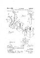
- FIG. 1 is a perspective view of an electrical contact that may be made in accordance with this invention
- FIG. 2 is a diagrammatic representation, in perspective, of a simplified form of apparatus that may be utilized in carrying out this invention
- FIG. 3 is a simplified sectional view of the apparatus taken along the line 3a3a of FIG. 2;
- FIG. 3b is a view illustrating the apparatus of FIG. 3a in a second position
- FIG. 4 is a sectional view taken along the line 4-4 of I FIG. 2;
- FIG. 5 is a sectional view taken along the line 5-5 of FIG. 2.
- FIG. 1 a bifurcated electrical contact, indicated generally as 10.
- the contact includes a contact body 12 of some suitable material, such as tinned phosphor bronze which is formed to provide positioning means 14, a proximal portion 16, and a distal portion 18.
- Proximal portion 16 is bifurcated for a substantial part of its length to provide tines 20 and 22 which have located thereon, in a prescribed position, contact points 24 and 26, respectively.
- the contact points are formed from a corrosion resistant material such as gold, silver, or an alloy thereof.
- Positioning means 14 which may be formed substantially intermediate the proximal and distal portions, provides for the proper orientation of contact 10 when inserted in a connector block. Distal portion 18, under ordinary circumstances, would project from the connector block so that an electrical connection might be made thereto.
- a connector of this type is highly reliable and exhibits extremely good life characteristics due to the plurality of independently actuable tines and the corrosion resistant contact points formed thereon. As may be seen from FIG. 1, should one of the tines be inadvertently bent or otherwise deformed, the other tine would still be capable of functioning to provide good electrical connection.
- Apparatus for makin such a contact is diagrammatically shown in FIG. 2 and comprises generally, a supply 28 of contact body material, shown to be an elongated strip 32, a supply 30 of contact point material 46 and presence of the contact points; and mechanical forming means are provided at station D for cutting, forming, and, if desired, bifurcating the contact.
- the supply 28 of contact body material comprises a spool 34, having the strip 32 wound thereon.
- the spool is rotatable by a motor 36 which is adapted to intermittently move the strip 32 in a longitudinal direction through the various Work stations A through D in accordance with a predetermined timed sequence from timing means, not shown.
- means 38 which is provided for attaching contact points 24 and 26 to strip 32, includes a reciprocable welder 40 and cutters 42 and 44.
- Contact point material 46 is fed from a spool of supply 30, by means not shown, through an upper welding electrode 47 which may form one terminal of an output winding on a welding transformer, not shown.
- This electrode may be coupled to the transformer either through a ground circuit comprising the frame of the machine on which it is mounted or it can be connected by a cable to the transformer, as desired.
- a lower electrode 48 suitably insulated from the frame, is connected to another terminal of the welding transformer and is comprised, in this instance, of a slide 59 mounted for transverse movement in a slideway 52 of a base block 54.
- Strip guide means 55 is formed in slide 50 and may comprise a longitudinally extending slot 56 which snugly engages the strip 32 for assuring accurate positioning when transverse movement is eifected.
- the apparatus at station A will perform as follows:
- the strip 32 of contact body material is fed to station A from the supply 28 and is positioned under electrode 47 of reciprocable welder 40 at a first contact point attaching station (see FIG. 3a).
- Actuating means not shown, causes electrode 47 to descend, and to make electrical contact with lower electrode 48 via the material 46 and the strip 32.
- the contact point material 46 is thereby spot welded to the strip 32.
- cutters 42 and 44 are actuated and approach and cut off the material 46. These cutters are adapted for cutting the stock in a manner for leaving welded to the strip 32 a body 57 (FIG. 3a), having a predetermined amount of roughly cylindrically shaped contact point material. After cutting, the welder 40 is automatically raised to an inoperative position.
- the slide 50 of lower electrode 48, with strip 32 constrained therein, is then moved transversely, by means which will be described hereinafter, to a second contact point attaching position (see FIG. 3b).
- the above-described welding and cutting cycle is repeated at the second position.
- a body 58 (FIG. 3b) of contact point material is attached to the strip 32 during this latter cycle.
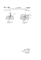
- FIG. 3a and FIG. 3] An exemplary means for effecting the desired relative transverse movement between the strip 32 and the welding apparatus 40 is illustrated in FIG. 3a and FIG. 3]).
- a connecting link 59 which is suitably fastened at one end to the slide 50, is connected at an opposite end to a rocker arm 60.
- the arm 60 is pivotally mounted on a stub shaft 61 and a free end thereof is provided with a cam follower 62.
- the cam follower is in operative engagement with a face cam 63 which is mounted on a cam drive shaft 64.
- the face cam 63 includes first and second dwell contours 65 and 66, respectively, and drive contours 67 and 68, respectively, for causing transverse movement of the slide 50.
- the motor 36 Upon completion of the welding and cutting at station A, the motor 36 is actuated and indexes the strip 32 longitudinally to station B, the distance moved being substantially equal to the length of the contact being made or a multiple thereof.
- station E means indicated generally as 70 (FIG. 4) is provided for contouring the bodies 57 and 58 to form the contact points 22 and 24.
- the means 70 comprises a peener 72 having dimples 74 in a face 76 thereof and it is actuated in proper timed sequence by means, not shown, but which may include a cam-lever arrangement such as is shown and described in previously mentioned U.S. Patent No. 3,114,828.
- the peener 72 descends to the strip 32 and the dimples 74 form the contact points.
- the shape of the dimples 74 determines the final configuration of the contact points and in this instance they will be hemispherical. However, other configurations, such as cylindrical and conical can also be formed.
- the motor 36 is again actuated and the strip 32 is advanced to the sensing station C whereat is provided means, indicated generally as 78, for sensing the presence or absence of the contact points.
- This sensing means is adapted to stop the machine when the absence of contact points is detected.
- the means 78 may comprise a micro-switch 80 having at detecting blade 82 projecting therefrom.
- the blade is actuable by means which may include a spring loaded depending rod 83 supported from upper die block 84, which, in turn, is mounted on a forming press.
- the strip is fed to stationD where mechanical forming operations including cutting, forming, and bifurcation take place.
- mechanical forming operations including cutting, forming, and bifurcation take place.
- These operations are performed by a cutting, forming, and bifurcating means 86 (FIG. 5) which comprises a stationary lower die block 88 and and upper, movable die block 84.
- Upper die block 84 is formed to provide contact point receiving recesses 90 and a bifurcating tongue 92.
- the recesses 90 are somewhat larger than the contact points to prevent them from being deformed during the cutting-forming operation.
- Lower die block 88 is adapted to receive the strip 32, as in a slot 94, and is also provided with a bifurcating tongue receiving slot 96. This slot 96 may extend entirely through the die and thus provide egress means for the scrap material removed during the bifurcation operation.
- the contact points are mounted at predetermined positions on a contact body member and are formed from a material differing from the material of the contact body. Individual handling of the contacts and multiple welder applications are avoided thereby providing increased accuracy and reduced cost of production.
- the means described above for elfecting the transverse movement is exemplary and other arrangements may 'be provided.
- the cam and rocker arm assembly could be replaced with a horizontally disposed fluid motor whose shaft could connect to link 59.
- the motor could,
- a method of making tined electrical contacts having a contoured precious metal contact point on each tine thereof from substantially a continuous metal strip intermittently movable in a given longitudinal direction comprising the steps of: advancing said strip in said longitudinal direction from a supply station to a first position at a contact point attaching station; attaching a first contact point to said strip at said attaching station; moving strip transversely of said longitudinal direction from said first position to a second position and attaching a second contact point to said strip; returning said strip to said first position; advancing said strip in said given longitudinal direction to a contact point contouring station; contouring said points while at said contouring station; advancing said strip in said given longitudinal direction to a contact point sensing station; sensing said points while at said sensing station; advancing said strip in said given longitudinal direction to a cutting and forming station; and cutting and forming said strip while at said cutting and forming station to provide an electrical contact having tines with a precious metal contact point formed on each tine.
Description
METHOD OF MAKING ELECTRICAL CONTACTS FROM STRIP STOCK Filed June 2, 1965 2 Sheets-Sheet 1 /e if Z6 I 22 INVENTOR. 7 WELDER 4 filo/ms f. Gmwva:
ATTOQNEY y 1968 T. E. GANNOE 3,382,575
METHOD OF MAKING ELECTRICAL CONTACTS FROM STRIP STOCK Filed June 2, 1965 2 Sheets-Sheet 2 INVENTOR. 77mm 5 .5. 64mm:
BY flTTOQ/VEY United States Patent 3,382,575 METHOD OF MAKING ELECTRICAL CONTACTS FROM STRIP STOCK Thomas Earl Gannoe, Warren, Pa., assignor to Sylvania Electric Products Inc., a corporation of Delaware Filed June 2, 1965, Ser. No. 460,693 1 Claim. (Cl. 29-630) ABSTRACT OF THE DISCLOSURE A method and apparatus for applying laterally spaced, noble metal contact points on continuous base metal strip material by effecting relative lateral movement between the strip and the contact point applying means at the point applying station.
This invention relates to the making of electrical contacts and more particularly to the making of electrical contacts comprised of a contact body having multiple contact points positioned thereon.
There is a need for a reliable, long-life electrical contact in complex electrical apparatus, such as computers and the like wherein contacts are utilized in large numbers. A known form of contact for use in such application comprises a body member and a single point of contact material positioned thereon for providing connection with a mating piece. A plurality of these contacts are generally arranged to form a connector.
In an illustrative example, a plurality of contacts might be arranged in a block of insulating material that is adapted for accepting and releasing an associated array of mating terminals on a printed circuit board. In addition to exhibiting a desired low electrical resistivity and corrosion resistance, the contact points must be capable of enduring repeated sliding connections which accompany the insertion and withdrawal of the mating terminals of the printed circuit board from the block. In providing these characteristics, it has been found advantageous to utilize a contact comprised of a contact body having two or more contact points.
Single point contacts of the type referred to have previously been manufactured by applying a discrete amount of contact point material, such as gold or other metal, at single preselected, spaced areas along a continuous metal strip. The contacts are subsequently thechanically formed from the strip. Apparatus for making this type of contact is disclosed in US. Patent 3,114,828, which is assigned to the assignee of this invention.
The need for a contact having two or more contact points introduces manufacturing requirements not previously encountered in making the single contact point form of contact. For example, the multiple contact points of a contact should be aligned accurately relative to each other and should be applied at the same position on individual contacts. In addition, it is desirable to accomplish this contact making with a minimum of complexity in order to reduce attending manufacturing costs.
It is, therefore, an object of this invention to enhance the manufacturing techniques for electrical contacts.
It is another object of this invention to provide a method of making an electrical contact having two or more contact points.
Another object of this invention is to provide an apparatus for making contacts having two or more contact points.
A contact configuration having two or more contact points and which is particularly adapted for use with printed circuit boards employs a bifurcated contact body having contact points applied to the individual tines.
A further object of the invention is to provide a method for making a contact of this type.
'ice
Still another object of this invention is to provide a method for making a contact of this type at a relatively small cost.
These and other objects are achieved, in one aspect of the invention, by a method for making, from continuous metal strip intermittently movable in a given longitudinal direction, electrical contacts having a contact body of a first metal and multiple contact points of a second metal formed thereon. The method comprises advancing the strip from a supply station to a first position at a contact point attaching station where means is provided for attaching contact points. A first contact point is attached to the strip at this station and relative transverse movement is sequentially effected between the attaching means and the strip. A second contact point is attached to the strip, this second contact point being spaced from the first point by a distance corresponding to the transverse movement.
For a better understanding of the present invention, together with other and further objects, advantages and capabilities thereof, reference is made to the following disclosure and appended claims in connection with the accompanying drawings in which:
FIG. 1 is a perspective view of an electrical contact that may be made in accordance with this invention;
FIG. 2 is a diagrammatic representation, in perspective, of a simplified form of apparatus that may be utilized in carrying out this invention;
FIG. 3 is a simplified sectional view of the apparatus taken along the line 3a3a of FIG. 2;
FIG. 3b is a view illustrating the apparatus of FIG. 3a in a second position;
FIG. 4 is a sectional view taken along the line 4-4 of I FIG. 2; and
FIG. 5 is a sectional view taken along the line 5-5 of FIG. 2.
Referring now to the drawings with greater particularity, in FIG. 1 is shown a bifurcated electrical contact, indicated generally as 10. The contact includes a contact body 12 of some suitable material, such as tinned phosphor bronze which is formed to provide positioning means 14, a proximal portion 16, and a distal portion 18. Proximal portion 16 is bifurcated for a substantial part of its length to provide tines 20 and 22 which have located thereon, in a prescribed position, contact points 24 and 26, respectively. The contact points are formed from a corrosion resistant material such as gold, silver, or an alloy thereof.
Positioning means 14, which may be formed substantially intermediate the proximal and distal portions, provides for the proper orientation of contact 10 when inserted in a connector block. Distal portion 18, under ordinary circumstances, would project from the connector block so that an electrical connection might be made thereto.
A connector of this type is highly reliable and exhibits extremely good life characteristics due to the plurality of independently actuable tines and the corrosion resistant contact points formed thereon. As may be seen from FIG. 1, should one of the tines be inadvertently bent or otherwise deformed, the other tine would still be capable of functioning to provide good electrical connection.
Apparatus for makin such a contact is diagrammatically shown in FIG. 2 and comprises generally, a supply 28 of contact body material, shown to be an elongated strip 32, a supply 30 of contact point material 46 and presence of the contact points; and mechanical forming means are provided at station D for cutting, forming, and, if desired, bifurcating the contact.
In greater detail, the supply 28 of contact body material comprises a spool 34, having the strip 32 wound thereon. The spool is rotatable by a motor 36 which is adapted to intermittently move the strip 32 in a longitudinal direction through the various Work stations A through D in accordance with a predetermined timed sequence from timing means, not shown.
At station A, means 38, which is provided for attaching contact points 24 and 26 to strip 32, includes a reciprocable welder 40 and cutters 42 and 44. Contact point material 46 is fed from a spool of supply 30, by means not shown, through an upper welding electrode 47 which may form one terminal of an output winding on a welding transformer, not shown. This electrode may be coupled to the transformer either through a ground circuit comprising the frame of the machine on which it is mounted or it can be connected by a cable to the transformer, as desired. A lower electrode 48, suitably insulated from the frame, is connected to another terminal of the welding transformer and is comprised, in this instance, of a slide 59 mounted for transverse movement in a slideway 52 of a base block 54. Strip guide means 55 is formed in slide 50 and may comprise a longitudinally extending slot 56 which snugly engages the strip 32 for assuring accurate positioning when transverse movement is eifected.
In operation, the apparatus at station A will perform as follows:
The strip 32 of contact body material is fed to station A from the supply 28 and is positioned under electrode 47 of reciprocable welder 40 at a first contact point attaching station (see FIG. 3a). Actuating means, not shown, causes electrode 47 to descend, and to make electrical contact with lower electrode 48 via the material 46 and the strip 32. The contact point material 46 is thereby spot welded to the strip 32. At the termination of welding current flow, cutters 42 and 44 are actuated and approach and cut off the material 46. These cutters are adapted for cutting the stock in a manner for leaving welded to the strip 32 a body 57 (FIG. 3a), having a predetermined amount of roughly cylindrically shaped contact point material. After cutting, the welder 40 is automatically raised to an inoperative position. The slide 50 of lower electrode 48, with strip 32 constrained therein, is then moved transversely, by means which will be described hereinafter, to a second contact point attaching position (see FIG. 3b). The above-described welding and cutting cycle is repeated at the second position. A body 58 (FIG. 3b) of contact point material is attached to the strip 32 during this latter cycle. The slide 50 is then returned to its initial position and the strip 32 is moved longitudinally to station B. Actuating means for performing the welding and cutting operations described are disclosed in greater detail in the above-mentioned U.S. Patent No. 3,114,828.
An exemplary means for effecting the desired relative transverse movement between the strip 32 and the welding apparatus 40 is illustrated in FIG. 3a and FIG. 3]). A connecting link 59, which is suitably fastened at one end to the slide 50, is connected at an opposite end to a rocker arm 60. The arm 60 is pivotally mounted on a stub shaft 61 and a free end thereof is provided with a cam follower 62. The cam follower is in operative engagement with a face cam 63 which is mounted on a cam drive shaft 64. The face cam 63 includes first and second dwell contours 65 and 66, respectively, and drive contours 67 and 68, respectively, for causing transverse movement of the slide 50.
As the cam 63 rotates counterclockwise, and during the interval of first contour cam dwell, the aforementioned welding and cutting operations form the body 57 (FIG. 3a). A transverse movement of slide 50 and strip 32 is then effected during the interval of cam drive contour 67. When a second dwell period corresponding to cam dwell contour 66 sequentially occurs, the material for a second contact point is welded to the strip 32 and cut to form the body 58 (FIG. 3b). Transverse movement returning the slide 50 to its initial position is subsequently effected by the cam drive contour 68.
It is to be noted that this description of the attachment of two contact points is by way of example only since, if it be desired to attach additional contact points, the cam 63 may be suitably modified to include additional dwell and drive contours.
Upon completion of the welding and cutting at station A, the motor 36 is actuated and indexes the strip 32 longitudinally to station B, the distance moved being substantially equal to the length of the contact being made or a multiple thereof. At station E means indicated generally as 70 (FIG. 4) is provided for contouring the bodies 57 and 58 to form the contact points 22 and 24. The means 70 comprises a peener 72 having dimples 74 in a face 76 thereof and it is actuated in proper timed sequence by means, not shown, but which may include a cam-lever arrangement such as is shown and described in previously mentioned U.S. Patent No. 3,114,828. During the cont-ouring cycle the peener 72 descends to the strip 32 and the dimples 74 form the contact points. The shape of the dimples 74 determines the final configuration of the contact points and in this instance they will be hemispherical. However, other configurations, such as cylindrical and conical can also be formed.
After completion of the contouring cycle the motor 36 is again actuated and the strip 32 is advanced to the sensing station C whereat is provided means, indicated generally as 78, for sensing the presence or absence of the contact points. This sensing means is adapted to stop the machine when the absence of contact points is detected. The means 78 may comprise a micro-switch 80 having at detecting blade 82 projecting therefrom. The blade is actuable by means which may include a spring loaded depending rod 83 supported from upper die block 84, which, in turn, is mounted on a forming press.
In operation, and in the presence of contact points, the end of blade 82 will strike the contact points when actuated by the depending rod on a downstroke of the press and will move an amount insufficient for operating switch 80. However, if there are no contact points present, the blade 82 will be depressed downward for a distance sufiicient to operate the switch, indicate a fault, and stop the machine.
Having had the presence of the contact points sensed, the strip is fed to stationD where mechanical forming operations including cutting, forming, and bifurcation take place. These operations are performed by a cutting, forming, and bifurcating means 86 (FIG. 5) which comprises a stationary lower die block 88 and and upper, movable die block 84. Upper die block 84 is formed to provide contact point receiving recesses 90 and a bifurcating tongue 92. The recesses 90 are somewhat larger than the contact points to prevent them from being deformed during the cutting-forming operation.
Lower die block 88 is adapted to receive the strip 32, as in a slot 94, and is also provided with a bifurcating tongue receiving slot 96. This slot 96 may extend entirely through the die and thus provide egress means for the scrap material removed during the bifurcation operation.
It is to be noted that once the machine is in operation the welding, contouring, sensing, and forming are all performed substantially simultaneously on different contacts during stationary periods of the longitudinal strip movement. To insure accurate placement of the contact points, it is, of course, possible to time the contouring operation to occur during the transverse movement of the slide 50 so that any vibrations set up by the hammering action entailed therewith will not interfere with the welding sequence.
Although the relative motion of strip 32 and the welding apparatus have been described to 'be transverse to the longitudinal axis of the strip 32, the relative motion of these elements along a line forming an angle greater than but less than 180 with respect to the longitudinal axis of the strip 32 is encompassed within the scope of the present invention.
There has thus been provided by this invention new and novel means for automatically attaching multiple contact points to an electrical contact. In a particular form of contact, the contact points are mounted at predetermined positions on a contact body member and are formed from a material differing from the material of the contact body. Individual handling of the contacts and multiple welder applications are avoided thereby providing increased accuracy and reduced cost of production.
Various changes may be made in the fabricating means described above without departing from the invention.
For example, the means described above for elfecting the transverse movement is exemplary and other arrangements may 'be provided. The cam and rocker arm assembly could be replaced with a horizontally disposed fluid motor whose shaft could connect to link 59. The motor could,
of course, be timed in any desired manner to eifect sequential displacement of the slide 50 and the strip 32 constrained therein.
In addition, it should also be pointed out that another obvious expedient would be to maintain the strip 32 stationary and mount the Welding apparatus upon a slide which could be actuated by any one of the means described above.
While there have been shown and described what are at present considered the preferred embodiments of the invention, it will be obvious to those skilled in the art that various changes and modifications may be made therein without departing from the scope of the invention as defined by the appended claim.
fit
What is claimed is:
1. A method of making tined electrical contacts having a contoured precious metal contact point on each tine thereof from substantially a continuous metal strip intermittently movable in a given longitudinal direction, comprising the steps of: advancing said strip in said longitudinal direction from a supply station to a first position at a contact point attaching station; attaching a first contact point to said strip at said attaching station; moving strip transversely of said longitudinal direction from said first position to a second position and attaching a second contact point to said strip; returning said strip to said first position; advancing said strip in said given longitudinal direction to a contact point contouring station; contouring said points while at said contouring station; advancing said strip in said given longitudinal direction to a contact point sensing station; sensing said points while at said sensing station; advancing said strip in said given longitudinal direction to a cutting and forming station; and cutting and forming said strip while at said cutting and forming station to provide an electrical contact having tines with a precious metal contact point formed on each tine.
References Cited UNITED STATES PATENTS 3,165,818 1/1965 Soffa et al 2l9-85 X 3,186,446 1/1965 Hunt -93 3,229,357 1/1966 Burstin 29-630 3,244,344 4/1966 Folk 228-15 X FOREIGN PATENTS 799,336 12/ 1956 Great Britain.
JOHN F. CAMPBELL, Primary Examiner.
R. W. CHURCH, Assistant Examiner.
Priority Applications (2)
| Application Number | Priority Date | Filing Date | Title |
|---|---|---|---|
| US460693A US3382575A (en) | 1965-06-02 | 1965-06-02 | Method of making electrical contacts from strip stock |
| US712433A US3509307A (en) | 1965-06-02 | 1968-03-12 | Apparatus for making electrical contacts from strip stock |
Applications Claiming Priority (1)
| Application Number | Priority Date | Filing Date | Title |
|---|---|---|---|
| US460693A US3382575A (en) | 1965-06-02 | 1965-06-02 | Method of making electrical contacts from strip stock |
Publications (1)
| Publication Number | Publication Date |
|---|---|
| US3382575A true US3382575A (en) | 1968-05-14 |
Family
ID=23829697
Family Applications (1)
| Application Number | Title | Priority Date | Filing Date |
|---|---|---|---|
| US460693A Expired - Lifetime US3382575A (en) | 1965-06-02 | 1965-06-02 | Method of making electrical contacts from strip stock |
Country Status (1)
| Country | Link |
|---|---|
| US (1) | US3382575A (en) |
Cited By (16)
| Publication number | Priority date | Publication date | Assignee | Title |
|---|---|---|---|---|
| US3485994A (en) * | 1966-10-12 | 1969-12-23 | Western Electric Co | Apparatus for resistance welding spaced contact elements onto a strip of material |
| US3575570A (en) * | 1968-12-06 | 1971-04-20 | Western Electric Co | Apparatus for fabricating a contact on an electrically conducting member |
| US3803711A (en) * | 1971-02-04 | 1974-04-16 | Texas Instruments Inc | Electrical contact and method of fabrication |
| US3894334A (en) * | 1973-05-31 | 1975-07-15 | Int Standard Electric Corp | Method of manufacturing contact springs |
| US3976240A (en) * | 1973-10-09 | 1976-08-24 | E. I. Du Pont De Nemours And Company | Apparatus for applying contacts |
| JPS51156458U (en) * | 1976-05-27 | 1976-12-13 | ||
| US4089106A (en) * | 1973-05-25 | 1978-05-16 | North American Specialties Corp. | Method for producing electrical contacts |
| US4925522A (en) * | 1989-08-21 | 1990-05-15 | Gte Products Corporation | Printed circuit assembly with contact dot |
| US5163850A (en) * | 1991-04-18 | 1992-11-17 | Polaroid Corporation | Electrostatic discharge protection devices for semiconductor chip packages |
| US5189275A (en) * | 1989-08-21 | 1993-02-23 | Gte Products Corporation | Printed circuit assembly with contact dot |
| US6152790A (en) * | 1999-10-21 | 2000-11-28 | Hewlett-Packard Company | Bifurcated contact with a connecting member that can add redundant contact points to single point connectors |
| US6183316B1 (en) * | 1999-10-21 | 2001-02-06 | Hewlett-Packard Company | Connector with redundant contact points |
| US6309262B1 (en) * | 1999-10-21 | 2001-10-30 | Hewlett-Packard Company | Bifurcated contact with a connecting member at the tip of the contact that provides redundant contact points |
| US6860766B2 (en) * | 2002-03-08 | 2005-03-01 | Cinch Connectors, Inc. | Electrical connector |
| US20070045874A1 (en) * | 1999-07-30 | 2007-03-01 | Formfactor, Inc. | Lithographic Type Microelectronic Spring Structures with Improved Contours |
| US20150364891A1 (en) * | 2013-02-22 | 2015-12-17 | Furukawa Electric Co., Ltd. | Terminal Manufacturing Apparatus and Welding Apparatus |
Citations (5)
| Publication number | Priority date | Publication date | Assignee | Title |
|---|---|---|---|---|
| GB799336A (en) * | 1955-12-14 | 1958-08-06 | Crompton Parkinson Ltd | Improvements relating to the electric arc welding of studs and similar bodies |
| US3165818A (en) * | 1960-10-18 | 1965-01-19 | Kulicke & Soffa Mfg Co | Method for mounting and bonding semiconductor wafers |
| US3186446A (en) * | 1961-05-09 | 1965-06-01 | Sylvania Electric Prod | Apparatus for attaching filamentary material |
| US3229357A (en) * | 1961-07-05 | 1966-01-18 | Schlatter Ag | Process and apparatus for manufacturing contact blades |
| US3244344A (en) * | 1963-12-30 | 1966-04-05 | Motorola Inc | Cutting and forming mechanism for bonders |
-
1965
- 1965-06-02 US US460693A patent/US3382575A/en not_active Expired - Lifetime
Patent Citations (5)
| Publication number | Priority date | Publication date | Assignee | Title |
|---|---|---|---|---|
| GB799336A (en) * | 1955-12-14 | 1958-08-06 | Crompton Parkinson Ltd | Improvements relating to the electric arc welding of studs and similar bodies |
| US3165818A (en) * | 1960-10-18 | 1965-01-19 | Kulicke & Soffa Mfg Co | Method for mounting and bonding semiconductor wafers |
| US3186446A (en) * | 1961-05-09 | 1965-06-01 | Sylvania Electric Prod | Apparatus for attaching filamentary material |
| US3229357A (en) * | 1961-07-05 | 1966-01-18 | Schlatter Ag | Process and apparatus for manufacturing contact blades |
| US3244344A (en) * | 1963-12-30 | 1966-04-05 | Motorola Inc | Cutting and forming mechanism for bonders |
Cited By (18)
| Publication number | Priority date | Publication date | Assignee | Title |
|---|---|---|---|---|
| US3485994A (en) * | 1966-10-12 | 1969-12-23 | Western Electric Co | Apparatus for resistance welding spaced contact elements onto a strip of material |
| US3575570A (en) * | 1968-12-06 | 1971-04-20 | Western Electric Co | Apparatus for fabricating a contact on an electrically conducting member |
| US3803711A (en) * | 1971-02-04 | 1974-04-16 | Texas Instruments Inc | Electrical contact and method of fabrication |
| US4089106A (en) * | 1973-05-25 | 1978-05-16 | North American Specialties Corp. | Method for producing electrical contacts |
| US3894334A (en) * | 1973-05-31 | 1975-07-15 | Int Standard Electric Corp | Method of manufacturing contact springs |
| US3976240A (en) * | 1973-10-09 | 1976-08-24 | E. I. Du Pont De Nemours And Company | Apparatus for applying contacts |
| JPS51156458U (en) * | 1976-05-27 | 1976-12-13 | ||
| US5189275A (en) * | 1989-08-21 | 1993-02-23 | Gte Products Corporation | Printed circuit assembly with contact dot |
| US4925522A (en) * | 1989-08-21 | 1990-05-15 | Gte Products Corporation | Printed circuit assembly with contact dot |
| US5163850A (en) * | 1991-04-18 | 1992-11-17 | Polaroid Corporation | Electrostatic discharge protection devices for semiconductor chip packages |
| US20070045874A1 (en) * | 1999-07-30 | 2007-03-01 | Formfactor, Inc. | Lithographic Type Microelectronic Spring Structures with Improved Contours |
| US7524194B2 (en) * | 1999-07-30 | 2009-04-28 | Formfactor, Inc. | Lithographic type microelectronic spring structures with improved contours |
| US6152790A (en) * | 1999-10-21 | 2000-11-28 | Hewlett-Packard Company | Bifurcated contact with a connecting member that can add redundant contact points to single point connectors |
| US6183316B1 (en) * | 1999-10-21 | 2001-02-06 | Hewlett-Packard Company | Connector with redundant contact points |
| US6309262B1 (en) * | 1999-10-21 | 2001-10-30 | Hewlett-Packard Company | Bifurcated contact with a connecting member at the tip of the contact that provides redundant contact points |
| US6860766B2 (en) * | 2002-03-08 | 2005-03-01 | Cinch Connectors, Inc. | Electrical connector |
| US20150364891A1 (en) * | 2013-02-22 | 2015-12-17 | Furukawa Electric Co., Ltd. | Terminal Manufacturing Apparatus and Welding Apparatus |
| US9985405B2 (en) * | 2013-02-22 | 2018-05-29 | Furukawa Automotive Systems Inc. | Terminal manufacturing apparatus and welding apparatus |
Similar Documents
| Publication | Publication Date | Title |
|---|---|---|
| US3382575A (en) | Method of making electrical contacts from strip stock | |
| US2977672A (en) | Method of making bonded wire circuit | |
| EP0872920A2 (en) | Continuous electronic stamping with offset carrier | |
| US3268851A (en) | Switch contact | |
| CN107611644A (en) | Spring contact and the socket for having used spring contact | |
| US4074424A (en) | Crimping and wire lead insertion machine | |
| US3509307A (en) | Apparatus for making electrical contacts from strip stock | |
| US4164065A (en) | Crimping and wire lead insertion machine having improved insertion means | |
| US4534603A (en) | Assembly of a contact spring and wire wrap terminal | |
| US3594889A (en) | Terminal-inserting machines having improved inside former | |
| US3510831A (en) | Solder well terminal with fine wire retaining prongs | |
| US3481018A (en) | Electrical connector crimping apparatus | |
| US3995365A (en) | Method of forming electrical contacts | |
| US3857154A (en) | Apparatus for positioning an end of a bendable wire-like article at a predetermined location on another article | |
| JPS5838897B2 (en) | Manufacturing method of lead wire frame for switchgear device | |
| US3386153A (en) | Method and apparatus for forming an insulated electrical connection | |
| US4099043A (en) | Progressive die welding of electrical contacts | |
| US2852755A (en) | Electric terminal | |
| CN111531100B (en) | Novel three-punch type cold heading rivet contact processing method | |
| US3727175A (en) | Fork-shaped contact spring to produce a separable electric connection | |
| US4575607A (en) | Rotary welding of electrical contacts in a progressive die | |
| JP4101861B2 (en) | Terminal for fusing | |
| US3974954A (en) | Apparatus for making tined electrical contacts | |
| US3967370A (en) | Method of manufacturing a multicontact switch | |
| US6725537B2 (en) | Method of connecting circuit element |