US3395073A - Suction roll assembly - Google Patents
Suction roll assembly Download PDFInfo
- Publication number
- US3395073A US3395073A US479160A US47916065A US3395073A US 3395073 A US3395073 A US 3395073A US 479160 A US479160 A US 479160A US 47916065 A US47916065 A US 47916065A US 3395073 A US3395073 A US 3395073A
- Authority
- US
- United States
- Prior art keywords
- shell
- suction
- roll
- journal
- sealing means
- Prior art date
- Legal status (The legal status is an assumption and is not a legal conclusion. Google has not performed a legal analysis and makes no representation as to the accuracy of the status listed.)
- Expired - Lifetime
Links
Images
Classifications
-
- D—TEXTILES; PAPER
- D21—PAPER-MAKING; PRODUCTION OF CELLULOSE
- D21F—PAPER-MAKING MACHINES; METHODS OF PRODUCING PAPER THEREON
- D21F3/00—Press section of machines for making continuous webs of paper
- D21F3/02—Wet presses
- D21F3/10—Suction rolls, e.g. couch rolls
Definitions
- This invention relates to suction roll apparatus of the type used in the manufacture of fibrous sheet material such as paper.
- the invention is directed to improvements in the manner of assembling various elements of the apparatus to provide improved and efficient operation.
- Suction roll apparatus requires a rotatable perforate roll or shell over which the sheet material is advanced and simultaneously therewith fluids are removed from the material by means of a stationary suction compartment located within the roll or shell to which a vacuum is applied.
- Longitudinal and transverse seals are provided for the suction compartment for the purpose of establishing a vacuum zone within the shell directly beneath the advancing material.
- the transverse seals are made adjustable relative to the longitudinal seals which are in a fixed position.
- the prior art arrangements for adjusting the transverse seals utilizes mechanical elements located within the suction compartment in the path of the extracted fluid and are subjected to inefficient operation by the accumulation of deposits thereon.
- One object of this invention therefore is to provide an arrangement for adjusting the transverse seals which over comes this problem and permits substantially continuous operation of the suction roll apparatus.
- Another object of the invention then is to improve this feature of the apparatus by providing an improved suction box and mounting arrangement which insures effective and free rotation of the shell.
- FIGURES 1a and 1b are views generally in longitudinal section of the suction roll apparatus.
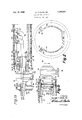
- FIGURE 2 is a transverse section view of the suction roll apparatus with parts removed for the purpose of clarity.
- a hollow cylinder having apertures 12 formed therein over substantially its entire surface to provide a suction roll for the removal of fluid from paper, felt, etc. when it is advanced over the outer surface of the roll as is customary in the paper, textile and similar industries.
- One end of the shell 10 is provided with an adaptor 14 which has a central flange 16, an outer journal 18 and an inner journal 20.
- the other end of the shell is provided with a generally similar adaptor 22 having a central flange 24, an outer journal 26 and an inner journal 28.
- the flange 16 is removably secured to one end of the roll 10 by bolt connections, as shown, and the flange 24 may be fixedly secured to the other end of the roll 10.
- the outer journals 18 and 26 are mounted respectively in fixed bearing structure indicated as 28 and 30.
- An arrangement for applying suction to the cylinder or roll 10 comprises a boxlike structure which is mounted in fixed position within the cylinder or roll 10 and is generally U-shaped in transverse cross section, as shown in FIGURE 2.
- the boxlike structure has a closed end wall 42 shown in FIGURE 1b and similar upstanding side walls 4444 as shown in FIGURE 2 which are interconnected by a base 46.
- the upstanding side walls 44-44 terminate in parallel upper edges 48-48 which provide spaces with the inner wall of the cylinder or roll 10.
- the upper edges 4848 will receive longitudinal seals which will determine the width of the suction zone as will be later described.
- the boxlike structure 40 has an apertured end wall 50 spaced from the opposing end wall 42 and the end walls 42 and 50 are provided respectively with inwardly extending flanges 52 and '54 which form supporting structure for the transverse seals as will also be described.
- a conduit 56 has a flanged end 58 which is fixedly secured to the apertured end wall 50 and extends through the journal 18 to be in communication at its outer end with a suction chamber 60.
- the outer end of the conduit 56 is closed by cap 62 and apertures 64 are provided in the conduit 56.
- the vacuum may be applied by means of connection 66.
- a longitudinal sealing strip assembly is provided at the upper edge 48 of each of the side walls 44-44.
- These assemblies as shown in FIGURE 2 are formed as a channel Within which is secured a packing or sealing strip of suitable material such as rubber or other pliant material.
- the material chosen should have a low coefficient of friction in order to minimize wear on the inner surface of the cylinder or roll 10 since, as shown in FIGURE 2, the sealing assemblies shown at S080 are maintained in contact with the cylinder inner surface.
- transverse sealing assemblies are formed by arcuate channel members 9090 which may be constructed generally like the sealing assemblies 80-80. Although not shown it will be understood that the transverse sealing assemblies will be sufficiently long to abut the longitudinal sealing assemblies 8080 in order to provide the sealed suction zone therewith.
- transverse sealing assemblies are accomplished in a manner which minimizes the problems and yet permits the adjustments to be made at least as elfectively as by the prior art.
- fluid actuators for each transverse assembly are similar and comprise, as shown in FIGURE 1, a cylinder 100 having a piston 102 therein which is movable within its cylinder by pressure fluid supplied to either end of the cylinders by pairs of lines 104 and 106 from a source located exteriorly of the roll but not shown.
- the lines 104 and 106 for each cylinder may extend conveniently, as shown, through the suction conduit 56 in sealed relation with its end plate 62.
- the cylinders 100100 are supported by transverse ribs 108 which extend between the inner faces of side walls 44-44 of the boxlike structure 40.
- Upper horizontal plates 110-110 are provided on the suction box as shown in FIGURES 1a and 1b to provide surfaces on which the transverse sealing assemblies 90-90 repose and are movable therealong to adjust the width of the sealing zone formed with the longitudinal sealing assemblies 80.
- Sets of linkages 112-112 interconnect the assemblies -90 with the pistons 102-102 and as shown, each linkage is formed of a lower and upper shaft arrangement which permits the cylinders -100 to be compactly arranged in the space between the inner extensions 52 and 54 and provides for horizontal adjustment of the assemblies 90 along the horizontal plates 110.
- Apparatus for extracting fluid from fibrous sheet material which comprises,
- outer heating means located exteriorly of each end of the shell for receiving respectively said first and said second outer journals
- suction box having a first cylindrical flange extension at one end concentric with and spaced from said first outer journal and a second cylindrical flange extension at its other end concentric with and spaced from said second outer journal,
- (k) means for moving the transverse sealing means relative to the longitudinal sealing means to adjust the length of the sealed area comprising a fluid actuated first piston and connections with the first transverse sealing means and a fluid actuated second piston and connections with the second transverse sealing means.
- Apparatus for extracting fluid from fibrous sheet material which comprises,
- outer bearing means located exteriorly of each end of the shell for receiving respectively said first and said second outer journals
- suction box having a first cylindrical flange extension at one end concentric with and spaced from said first outer journal and a second cylindrical flange extension at its other end concentric with and spaced from said second outer journal,
- (k) means for moving the transverse sealing means relative to the longitudinal sealing means to adjust the length of the sealed area comprising pistoncylinder means having a first linkage for moving the first transverse sealing means longitudinally and a second linkage for moving the second transverse sealing means longitudinally and,
- Apparatus for extracting fluid from fibrous sheet material which comprises,
- outer bearing means located exteriorly of each end of the shell for receiving respectively said first and said second outer journals
- suction box having a first cylindrical flange extension at one end concentric with and spaced from said first outer journal and a second cylindrical flange extension at its other end concentric with and spaced from said second outer journal,
- (k) means for moving the transverse sealing means relative to the longitudinal sealing means which comprises a pair of cylinders aligned in tandem substantially in the plane of the longitudinal edges of the suction box each having a fluid actuated piston therein with one piston having connections with said first transverse sealing means and the other having a connection with said second transverse sealing means.
Description
y W68 w. P. DAVIS. SR
SUCTION ROLL ASSEMBLY Filed Aug. 12, 1965 I N v INVENTOR.
WILLM P DAVIS, SR.
A TTORNV United States Patent O 3,395,073 SUCTION ROLL ASSEMBLY William P. Davis, Sr., 320 E. Lancaster Ave., Downingtowu, Pa. 19335 Filed Aug. 12, 1965, Ser. No. 479,160 3 Claims. (Cl. 162-369) ABSTRACT OF THE DISCLOSURE An apparatus for extracting fluid from a fibrous web including a horizontal perforated shell, first and second adapters providing first and second adapters on each side of the shell, a sealed suction box within the shell and a source of vacuum connected to the suction box.
This invention relates to suction roll apparatus of the type used in the manufacture of fibrous sheet material such as paper. In particular, the invention is directed to improvements in the manner of assembling various elements of the apparatus to provide improved and efficient operation.
Suction roll apparatus requires a rotatable perforate roll or shell over which the sheet material is advanced and simultaneously therewith fluids are removed from the material by means of a stationary suction compartment located within the roll or shell to which a vacuum is applied. Longitudinal and transverse seals are provided for the suction compartment for the purpose of establishing a vacuum zone within the shell directly beneath the advancing material. In order to take care of variations in the widths of the sheet material the transverse seals are made adjustable relative to the longitudinal seals which are in a fixed position.
The prior art arrangements for adjusting the transverse seals utilizes mechanical elements located within the suction compartment in the path of the extracted fluid and are subjected to inefficient operation by the accumulation of deposits thereon.
One object of this invention therefore is to provide an arrangement for adjusting the transverse seals which over comes this problem and permits substantially continuous operation of the suction roll apparatus.
Since the shell or suction roll rotates relative to the suction equipment, a problem is presented in mounting such equipment to permit free rotation of the shell and to prevent frictional contact between the shell and the suction equipment, particularly the suction box structure forming the suction compartment.
Another object of the invention then is to improve this feature of the apparatus by providing an improved suction box and mounting arrangement which insures effective and free rotation of the shell.
Other objects and advantages of the invention will be apparent from a better understanding of the invention which may be had from the following detailed description of the accompanying drawing wherein:
FIGURES 1a and 1b are views generally in longitudinal section of the suction roll apparatus.
FIGURE 2 is a transverse section view of the suction roll apparatus with parts removed for the purpose of clarity.
At is indicated a hollow cylinder having apertures 12 formed therein over substantially its entire surface to provide a suction roll for the removal of fluid from paper, felt, etc. when it is advanced over the outer surface of the roll as is customary in the paper, textile and similar industries. One end of the shell 10 is provided with an adaptor 14 which has a central flange 16, an outer journal 18 and an inner journal 20. The other end of the shell is provided with a generally similar adaptor 22 having a central flange 24, an outer journal 26 and an inner journal 28. The flange 16 is removably secured to one end of the roll 10 by bolt connections, as shown, and the flange 24 may be fixedly secured to the other end of the roll 10. The outer journals 18 and 26 are mounted respectively in fixed bearing structure indicated as 28 and 30. Since the one flange 16 is removably secured to the roll 10, access is provided to the interior of the roll and this flange is also provided with one or more openings 32 permitting access to the interior of the roll Without removing the flange 16. The above described structure permits rotation of the roll 10 through a shaft 34 extending from the journal 26.
An arrangement for applying suction to the cylinder or roll 10 comprises a boxlike structure which is mounted in fixed position within the cylinder or roll 10 and is generally U-shaped in transverse cross section, as shown in FIGURE 2. The boxlike structure has a closed end wall 42 shown in FIGURE 1b and similar upstanding side walls 4444 as shown in FIGURE 2 which are interconnected by a base 46. The upstanding side walls 44-44 terminate in parallel upper edges 48-48 which provide spaces with the inner wall of the cylinder or roll 10. The upper edges 4848 will receive longitudinal seals which will determine the width of the suction zone as will be later described.
The boxlike structure 40 has an apertured end wall 50 spaced from the opposing end wall 42 and the end walls 42 and 50 are provided respectively with inwardly extending flanges 52 and '54 which form supporting structure for the transverse seals as will also be described. A conduit 56 has a flanged end 58 which is fixedly secured to the apertured end wall 50 and extends through the journal 18 to be in communication at its outer end with a suction chamber 60. For this purpose the outer end of the conduit 56 is closed by cap 62 and apertures 64 are provided in the conduit 56. The vacuum may be applied by means of connection 66.
From the above description it should be apparent that the cylinder or roll 10 and adapters 14 and 22 rotate while the structure which forms the vacuum system is fixed. In order to provide more efficient rotation, inner sets of roller bearings and 72 are provided as shown. An inner raceway is formed for the bearings 70 by the inner journal 20 and an outer raceway is provided by a cylindrical extension 74 on the boxlike structure 40. In a similar manner the inner raceway for bearings 72 is formed by journal 28 and the outer raceway by cylindrical extension 76 on the boxlike structure 40. Thus, the boxlike structure 40 is supported on the inner journals 20 and 28 of the respective adapters 14 and 22. Suitable lubricant seals are shown in association with the bearings 70 and 72 but are not further identified since bearing seals are a common expedient for bearings.
The above described structure will be disposed in a generally horizontal position on supports 7878 and the paper, felt or other material will be in contact over an area of the cylinder or roll surface as the material advances t'herealong. In order to effectively remove liquid therefrom provision is made for applying suction to this area of the cylinder or roll. For this purpose, a longitudinal sealing strip assembly is provided at the upper edge 48 of each of the side walls 44-44. These assemblies as shown in FIGURE 2 are formed as a channel Within which is secured a packing or sealing strip of suitable material such as rubber or other pliant material. The material chosen should have a low coefficient of friction in order to minimize wear on the inner surface of the cylinder or roll 10 since, as shown in FIGURE 2, the sealing assemblies shown at S080 are maintained in contact with the cylinder inner surface.
As shown in FIGURE 1, similar transverse sealing assemblies are formed by arcuate channel members 9090 which may be constructed generally like the sealing assemblies 80-80. Although not shown it will be understood that the transverse sealing assemblies will be sufficiently long to abut the longitudinal sealing assemblies 8080 in order to provide the sealed suction zone therewith.
Problems have existed in this art in the adjusting of the transverse sealing assemblies to adapt the suction zone to the width of the paper, felt or other material which is being advanced over the rolls. This has been accomplished heretofore by mechanical equipment involving axial shafts connecting arms, gearing, etc. such, for example, as the equipment shown in Patent 1,800,149. The mechanical equipment is located in the path of any pliant and loose material which may fall into the cylinder to adversely affect the operation of the equipment. Additionally, the faulty equipment presents an expensive and time consuming maintenance problem.
By the present invention, adjustment of the transverse sealing assemblies is accomplished in a manner which minimizes the problems and yet permits the adjustments to be made at least as elfectively as by the prior art. This is accomplished by the provision of fluid actuators for each transverse assembly. These are similar and comprise, as shown in FIGURE 1, a cylinder 100 having a piston 102 therein which is movable within its cylinder by pressure fluid supplied to either end of the cylinders by pairs of lines 104 and 106 from a source located exteriorly of the roll but not shown. The lines 104 and 106 for each cylinder may extend conveniently, as shown, through the suction conduit 56 in sealed relation with its end plate 62. The cylinders 100100 are supported by transverse ribs 108 which extend between the inner faces of side walls 44-44 of the boxlike structure 40.
Upper horizontal plates 110-110 are provided on the suction box as shown in FIGURES 1a and 1b to provide surfaces on which the transverse sealing assemblies 90-90 repose and are movable therealong to adjust the width of the sealing zone formed with the longitudinal sealing assemblies 80. Sets of linkages 112-112 interconnect the assemblies -90 with the pistons 102-102 and as shown, each linkage is formed of a lower and upper shaft arrangement which permits the cylinders -100 to be compactly arranged in the space between the inner extensions 52 and 54 and provides for horizontal adjustment of the assemblies 90 along the horizontal plates 110.
While a preferred embodiment of the invention is shown in the drawings, it should be understood that the invention may be varied from the showing without departing from the spirit or scope of the invention which is to be limited only by the appended claims.
I claim:
1. Apparatus for extracting fluid from fibrous sheet material which comprises,
(a) a horizontally disposed cylindrical shell having perforations communicating through substantially its entire surface,
(b) a first adapter having an outwardly extending flange secured to the shell adjacent one end and providing a first inner journal and a first outer journal,
(c) a second adapter having an outwardly extending flange secured to the shell adjacent its other end and providing a second inner journal and a second outer journal,
(d) outer heating means located exteriorly of each end of the shell for receiving respectively said first and said second outer journals,
(e) a suction box within said shell having opposed vertical end walls and longitudinal side wall structure,
(f) said suction box having a first cylindrical flange extension at one end concentric with and spaced from said first outer journal and a second cylindrical flange extension at its other end concentric with and spaced from said second outer journal,
(g) inner bearing means between each flange extension and each. outer journal supporting the suction box and permitting free rotation of the shell and adapters relative thereto on the outer and inner bearing means,
(h) means for applying suction to sheet material as it is advanced over the shell which comprises an axial passageway in one of the adapters communicating with an exterior vacuum source and the interior of the shell,
(i) an opening on the suction box located directly beneath the sheet material forming longitudinal edges having fixed longitudinal sealing means extending therealong in contact with the inner surface of the shell,
(j) a first transverse sealing means supported by one of said cylindrical extensions and a second transverse sealing means supported by the other of said cylindrical extensions and positioned to provide a sealed area with the longitudinal sealing means, and
(k) means for moving the transverse sealing means relative to the longitudinal sealing means to adjust the length of the sealed area comprising a fluid actuated first piston and connections with the first transverse sealing means and a fluid actuated second piston and connections with the second transverse sealing means.
2, Apparatus for extracting fluid from fibrous sheet material which comprises,
(a) a horizontally disposed cylindrical shell having perforations communicating through substantially its entire surface,
(b) a first adapter having an outwardly extending flange secured to the shell adjacent one end and providing a first inner journal and a first outer journal,
(c) a second adapter having an outwardly extending flange secured to the shell adjacent its other end and providing a second inner journal and a second outer journal,
(d) outer bearing means located exteriorly of each end of the shell for receiving respectively said first and said second outer journals,
(e) a suction box within said shell having opposed vertical end walls and longitudinal side wall structure,
(f) said suction box having a first cylindrical flange extension at one end concentric with and spaced from said first outer journal and a second cylindrical flange extension at its other end concentric with and spaced from said second outer journal,
(g) inner bearing means between each flange extension and each outer journal supporting the suction box and permitting free rotation of the shell and adapters relative thereto on the outer and inner bearing means,
(h) means for applying suction to sheet material as it is advanced over the shell which comprises an axial passageway in one of the adapters communicating with an exterior vacuum and the interior of the shell,
(i) an opening on the suction box located directly beneath the sheet material forming longitudinal edges having fixed longitudinal sealing means extending therealong in contact with the inner surface of the shell,
(j) a first transverse sealing means supported by one of said cylindrical extensions and a second transverse sealing means supported by the other of said cylindrical extensions and positioned to provide a sealed area with the longitudinal sealing means,
(k) means for moving the transverse sealing means relative to the longitudinal sealing means to adjust the length of the sealed area comprising pistoncylinder means having a first linkage for moving the first transverse sealing means longitudinally and a second linkage for moving the second transverse sealing means longitudinally and,
(l) a fluid source exteriorly of the apparatus having fluid connections to the cylinder means extending through the axial passageway of the one adapter for operating the piston-cylinder to vary the width of the sealed area.
3. Apparatus for extracting fluid from fibrous sheet material which comprises,
(a) a horizontally disposed cylindrical shell having perforations communicating through substantially its entire surface,
(b) a first adapter having an outwardly extending flange secured to the shell adjacent one end and providing a first inner journal and a first outer journal,
(c) a second adapter having an outwardly extending flange secured to the shell adjacent its other end and providing a second inner journal and a second outer journal,
(d) outer bearing means located exteriorly of each end of the shell for receiving respectively said first and said second outer journals,
(e) a suction box within said shell having opposed vertical end walls and longitudinal side wall structure,
(f) said suction box having a first cylindrical flange extension at one end concentric with and spaced from said first outer journal and a second cylindrical flange extension at its other end concentric with and spaced from said second outer journal,
(g) inner bearing means between each flange extension and each outer journal supporting the suction box and permitting free rotation of the shell and adapters relative thereto on the outer and inner bearing means,
(h) means for applying suction to sheet material as it is advanced over the shell which comprises an axial passageway in one of the adapters communicating with an exterior vacuum source and the interior of the shell,
(i) an opening on the suction box located directly beneath the sheet material forming longitudinal edges having fixed longitudinal sealing means extending therealong in contact with the inner surface of the shell,
(j) a first transverse sealing means supported by one of said cylindrical extensions and a second transverse sealing means supported by the other of said cylindrical extensions and positioned to provide a sealed area with the longitudinal sealing means, and,
(k) means for moving the transverse sealing means relative to the longitudinal sealing means which comprises a pair of cylinders aligned in tandem substantially in the plane of the longitudinal edges of the suction box each having a fluid actuated piston therein with one piston having connections with said first transverse sealing means and the other having a connection with said second transverse sealing means.
References Cited UNITED STATES PATENTS 2,714,342 8/1955 Beachler 162370 3,171,776 3/1965 Hart et a1 162-469 1,800,149 4/1931 Miller et al. 2,338,465 1/ 1944 Street. 2,969,837 1/1961 Reynar. 3,019,479 2/1962 Erickson et al.
DONALL H. SYLVESTER, Primary Examiner.
ALBERT C. HODGSON, Assistant Examiner,
Priority Applications (1)
| Application Number | Priority Date | Filing Date | Title |
|---|---|---|---|
| US479160A US3395073A (en) | 1965-08-12 | 1965-08-12 | Suction roll assembly |
Applications Claiming Priority (1)
| Application Number | Priority Date | Filing Date | Title |
|---|---|---|---|
| US479160A US3395073A (en) | 1965-08-12 | 1965-08-12 | Suction roll assembly |
Publications (1)
| Publication Number | Publication Date |
|---|---|
| US3395073A true US3395073A (en) | 1968-07-30 |
Family
ID=23902892
Family Applications (1)
| Application Number | Title | Priority Date | Filing Date |
|---|---|---|---|
| US479160A Expired - Lifetime US3395073A (en) | 1965-08-12 | 1965-08-12 | Suction roll assembly |
Country Status (1)
| Country | Link |
|---|---|
| US (1) | US3395073A (en) |
Cited By (16)
| Publication number | Priority date | Publication date | Assignee | Title |
|---|---|---|---|---|
| US4905379A (en) * | 1987-02-13 | 1990-03-06 | Beloit Corporation | Intermediate vacuum roll for dryer |
| US4934067A (en) * | 1987-02-13 | 1990-06-19 | Beloit Corporation | Apparatus for drying a web |
| US5065529A (en) * | 1987-02-13 | 1991-11-19 | Beloit Corporation | Apparatus for drying a web |
| US5144758A (en) * | 1987-02-13 | 1992-09-08 | Borgeir Skaugen | Apparatus for drying a web |
| US5249372A (en) * | 1987-02-13 | 1993-10-05 | Beloit Technologies, Inc. | Apparatus for drying a web |
| US5279049A (en) * | 1987-02-13 | 1994-01-18 | Beloit Technologies, Inc. | Process for the restrained drying of a paper web |
| US5294514A (en) * | 1992-03-27 | 1994-03-15 | Eastman Kodak Company | Vacuum roll separation system for photographic paper |
| US5404653A (en) * | 1987-02-13 | 1995-04-11 | Beloit Technologies, Inc. | Apparatus for drying a web |
| US5507104A (en) * | 1987-02-13 | 1996-04-16 | Beloit Technologies, Inc. | Web drying apparatus |
| US5542193A (en) * | 1992-04-24 | 1996-08-06 | Beloit Technologies, Inc. | Dryer group for curl control |
| US5884415A (en) * | 1992-04-24 | 1999-03-23 | Beloit Technologies, Inc. | Paper making machine providing curl control |
| US6049999A (en) * | 1987-02-13 | 2000-04-18 | Beloit Technologies, Inc. | Machine and process for the restrained drying of a paper web |
| DE10258289A1 (en) * | 2002-12-13 | 2004-07-29 | Voith Paper Patent Gmbh | adjusting |
| WO2011027031A1 (en) * | 2009-09-03 | 2011-03-10 | Metso Paper, Inc. | Roll shell and roll |
| CN102995480A (en) * | 2012-11-29 | 2013-03-27 | 无锡市洪成造纸机械有限公司 | Improved vacuum box structure of vacuum suction shifting roller |
| DE202024100389U1 (en) | 2023-02-14 | 2024-02-06 | Valmet Technologies Oy | Control device for the suction roll of a fiber web machine |
Citations (6)
| Publication number | Priority date | Publication date | Assignee | Title |
|---|---|---|---|---|
| US1800149A (en) * | 1928-11-16 | 1931-04-07 | Downingtown Mfg Co | Pneumatic suction box for suction rolls |
| US2338465A (en) * | 1938-05-19 | 1944-01-04 | Downingtown Mfg Co | Suction roll |
| US2714342A (en) * | 1950-11-02 | 1955-08-02 | Beloit Iron Works | Suction roll |
| US2969837A (en) * | 1958-06-10 | 1961-01-31 | Layton Greenfield Inc | Suction roll construction |
| US3019479A (en) * | 1957-03-21 | 1962-02-06 | Schubert | Press deckle assembly |
| US3171776A (en) * | 1962-12-12 | 1965-03-02 | Beloit Corp | Bearing extraction device for a suction press roll |
-
1965
- 1965-08-12 US US479160A patent/US3395073A/en not_active Expired - Lifetime
Patent Citations (6)
| Publication number | Priority date | Publication date | Assignee | Title |
|---|---|---|---|---|
| US1800149A (en) * | 1928-11-16 | 1931-04-07 | Downingtown Mfg Co | Pneumatic suction box for suction rolls |
| US2338465A (en) * | 1938-05-19 | 1944-01-04 | Downingtown Mfg Co | Suction roll |
| US2714342A (en) * | 1950-11-02 | 1955-08-02 | Beloit Iron Works | Suction roll |
| US3019479A (en) * | 1957-03-21 | 1962-02-06 | Schubert | Press deckle assembly |
| US2969837A (en) * | 1958-06-10 | 1961-01-31 | Layton Greenfield Inc | Suction roll construction |
| US3171776A (en) * | 1962-12-12 | 1965-03-02 | Beloit Corp | Bearing extraction device for a suction press roll |
Cited By (20)
| Publication number | Priority date | Publication date | Assignee | Title |
|---|---|---|---|---|
| US6049999A (en) * | 1987-02-13 | 2000-04-18 | Beloit Technologies, Inc. | Machine and process for the restrained drying of a paper web |
| US5832625A (en) * | 1987-02-13 | 1998-11-10 | Beloit Technologies, Inc. | Apparatus for drying a web |
| US5065529A (en) * | 1987-02-13 | 1991-11-19 | Beloit Corporation | Apparatus for drying a web |
| US5144758A (en) * | 1987-02-13 | 1992-09-08 | Borgeir Skaugen | Apparatus for drying a web |
| US5249372A (en) * | 1987-02-13 | 1993-10-05 | Beloit Technologies, Inc. | Apparatus for drying a web |
| US5279049A (en) * | 1987-02-13 | 1994-01-18 | Beloit Technologies, Inc. | Process for the restrained drying of a paper web |
| US5404653A (en) * | 1987-02-13 | 1995-04-11 | Beloit Technologies, Inc. | Apparatus for drying a web |
| US5507104A (en) * | 1987-02-13 | 1996-04-16 | Beloit Technologies, Inc. | Web drying apparatus |
| US4905379A (en) * | 1987-02-13 | 1990-03-06 | Beloit Corporation | Intermediate vacuum roll for dryer |
| US4934067A (en) * | 1987-02-13 | 1990-06-19 | Beloit Corporation | Apparatus for drying a web |
| US5636448A (en) * | 1987-02-13 | 1997-06-10 | Beloit Technologies, Inc. | Web drying apparatus |
| US5628124A (en) * | 1987-02-13 | 1997-05-13 | Beloit Technologies, Inc. | Apparatus for drying a web |
| US5368978A (en) * | 1992-03-27 | 1994-11-29 | Eastman Kodak Company | Delamination systems for photographic print materials |
| US5294514A (en) * | 1992-03-27 | 1994-03-15 | Eastman Kodak Company | Vacuum roll separation system for photographic paper |
| US5884415A (en) * | 1992-04-24 | 1999-03-23 | Beloit Technologies, Inc. | Paper making machine providing curl control |
| US5542193A (en) * | 1992-04-24 | 1996-08-06 | Beloit Technologies, Inc. | Dryer group for curl control |
| DE10258289A1 (en) * | 2002-12-13 | 2004-07-29 | Voith Paper Patent Gmbh | adjusting |
| WO2011027031A1 (en) * | 2009-09-03 | 2011-03-10 | Metso Paper, Inc. | Roll shell and roll |
| CN102995480A (en) * | 2012-11-29 | 2013-03-27 | 无锡市洪成造纸机械有限公司 | Improved vacuum box structure of vacuum suction shifting roller |
| DE202024100389U1 (en) | 2023-02-14 | 2024-02-06 | Valmet Technologies Oy | Control device for the suction roll of a fiber web machine |
Similar Documents
| Publication | Publication Date | Title |
|---|---|---|
| US3395073A (en) | Suction roll assembly | |
| US3974026A (en) | Belt press with rotatable cylinder and adjustable pressure member | |
| US3638292A (en) | Roll for applying uniform pressure | |
| DE3832324C2 (en) | ||
| ES8501032A1 (en) | Dryer felt run | |
| EP0428470B1 (en) | Felt turning roll | |
| US2312519A (en) | Balanced seal for suction rolls | |
| US1834852A (en) | Paper making machinery | |
| US2578551A (en) | Suction roll seal assembly | |
| GB2163187A (en) | Dryer section drive arrangement for papermaking machines | |
| US1595240A (en) | Vacuum seal, method and apparatus | |
| US2199455A (en) | Suction roll | |
| US1782215A (en) | Apparatus for producing felted fibrous board | |
| DE3734524C2 (en) | ||
| US2709398A (en) | Suction transfer assembly with deckle edge control | |
| GB2124670A (en) | Dryer section drive arrangement for papermaking machines | |
| US3036385A (en) | Tube type dryer | |
| US2115725A (en) | Rotary printing machine | |
| US1600509A (en) | Paper-machine press | |
| US3954557A (en) | Perforated compactor bar | |
| US1091941A (en) | Rotary suction-roll or vacuum couch-roll for use in paper-making machines. | |
| EP0147352B1 (en) | Extended nip press | |
| US3325351A (en) | Water-extracting device in felt and press section for paper machines | |
| US2561282A (en) | Shielding shoe for filters | |
| CA1240357A (en) | Self-adjusting minimum clearance bearing |