US341237A - Bicycle - Google Patents
Bicycle Download PDFInfo
- Publication number
- US341237A US341237A US341237DA US341237A US 341237 A US341237 A US 341237A US 341237D A US341237D A US 341237DA US 341237 A US341237 A US 341237A
- Authority
- US
- United States
- Prior art keywords
- wheel
- hub
- wheels
- axle
- speed
- Prior art date
- Legal status (The legal status is an assumption and is not a legal conclusion. Google has not performed a legal analysis and makes no representation as to the accuracy of the status listed.)
- Expired - Lifetime
Links
- 238000010276 construction Methods 0.000 description 4
- 206010022114 Injury Diseases 0.000 description 2
- 210000000614 Ribs Anatomy 0.000 description 2
- 230000001174 ascending Effects 0.000 description 2
- 230000003247 decreasing Effects 0.000 description 2
Images
Classifications
-
- B—PERFORMING OPERATIONS; TRANSPORTING
- B62—LAND VEHICLES FOR TRAVELLING OTHERWISE THAN ON RAILS
- B62M—RIDER PROPULSION OF WHEELED VEHICLES OR SLEDGES; POWERED PROPULSION OF SLEDGES OR SINGLE-TRACK CYCLES; TRANSMISSIONS SPECIALLY ADAPTED FOR SUCH VEHICLES
- B62M25/00—Actuators for gearing speed-change mechanisms specially adapted for cycles
- B62M25/08—Actuators for gearing speed-change mechanisms specially adapted for cycles with electrical or fluid transmitting systems
Definitions
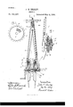
- FIG. 1 is a front elevation showing my improvements properly combined.
- Fig. ⁇ 2 shows, considerably enlarged, those parts of 1 which are embraced by line a; x.
- Fig. 3 is an inner face view of the sprocket-wheel 7, and isintended to illustrate the movable part of the ⁇ cluteh which I- make use of,'as hereinafter fully described.
- My improvements relate to bicycles as now colnmonly constructed, my immediate object being to connect with such bicycles certain combinations of mechanisms by means of which greater speed may be attained on level ground, when desired, also greater leverage may be obtained for climbing ⁇ steep grades, these mechanisms being under the complete control ofthe rider and adapted to be used or not, as he may elect.
- Fig. 1 represents the so-called fork7 of a bicycle-frame, having secured to its upper portion a steering head and handles, all of the usual construction. Pivoted in the depending free endsfof said fork are journal-bearings 3, in which the axial shaft l rotates, said shaft being provided with cranks and pedals, the latter not being shown here.
- wheels 7 and 8 are similar sprocket-wheels, 910, connected with those first referred to by endless chains 11 12.
- wheel 9 is secured by spline or set-screw to axle 4, and wheel l() is secured to the hub 5, which is looselyiitted on said axle.
- XVheel 9 is small and corresponds in size with the inner wheel, S, on stud 6.
- the hub-wheel 10 is preferably of the same diameter as the wheel 7.
- This system of chains and sprocketwheels necessitates a quicker movement of the feet to keep up the speed, but also materially reduces the weight of pressure that must be exerted by therider in ascending steep grades, the quick motion of the feet and legs hobos unobjectionable,for the reason that it is kept u p but a Vfew minutes at a time.
- Rod 19 passes downward within the arm of the fork, being thus protected from injury, and also concealed from view.
- the opposite system (of sprocket wheels and chains) is the I5 same in principle as that just described, and
- lever 22 is raised to disengage wheels 9 and 10, and lever 20 is forced downward to operate the connecting-clutch of wheels 7 and 4o S.
- levers 22 and 2O may be respectively opened Vand closed to return to the medium of leverage.
- lever 22 is raised and lever 21 forced downward, thus throwing into working engagement the speed- 4 multiplying train, as shown at the right-hand side of Fig. 1. W'hen moving rapidly downgrade, all three of the clutches may be thrown out of engagement, in which case the cranks and axle are at rest until one of the clutches 5 is again brought into use.
- claim-4 In combination with the fork, axle, and hub of a bicycle, mechanism for increasing the speed, consisting of a train of sprocket wheels 6 and chains arranged and connected as described, and clutch mechanism, substantially as described, for operating the same, mechanism for decreasing the speed, consisting of a train of sprocket wheels and chains arranged 6 and connected as described, and clutch mechanism, substantially as described, for operating the same, and independent clutch mechanism, substantially as shown and described, by means of which the crank-aXle and hub 7 maybe connected at will to produce an intermediate or normal speed.
- a hub rotatably fixed on said axle, a disk securely fixed to said hub, as described, 7 a elutclrdisk of the form described, rotatably located on said aXle adjacent to said hub-disk, and clutch mechanism, substantially as herein described, for connecting and disconnecting said hub-disk and clutch-disk, for the object S specified.
Description
(No Model.)
BICYCLE.
Patented May 4, 1886.
IlNrTED STATES PATENT OFFICE.
JO'HhT I'I. HEALEY, OF VOLUNTOIVN, CONNECTICUT.
BICYCLE.
QBPEFICATION forming part of Letters Patent No. 341,237, dated May 4,1886.
Appliration iiled January 1l, 1886. Serial No. 1SS.19I.
To @ZZ whom it may concern.-
Be it known that I, JOHN H. HEALEY, a citizen of the United States, residing at Voluntown, in the county of New London and State of Connecticut, have invented certain new and useful Improvements in Bicycles, which improvements are fully set forth and described inthe following specification, reference being had to the accompanying drawings, in which- Figure 1 is a front elevation showing my improvements properly combined. In said figure I have shown only such portions of a bicycle of ordinary construction as are necessary to explain said improvements, and have cut away the wheelvhuos to expose my newlyadded niechanism. Fig. `2 shows, considerably enlarged, those parts of 1 which are embraced by line a; x. Fig. 3 is an inner face view of the sprocket-wheel 7, and isintended to illustrate the movable part of the`cluteh which I- make use of,'as hereinafter fully described.
My improvements relate to bicycles as now colnmonly constructed, my immediate object being to connect with such bicycles certain combinations of mechanisms by means of which greater speed may be attained on level ground, when desired, also greater leverage may be obtained for climbing` steep grades, these mechanisms being under the complete control ofthe rider and adapted to be used or not, as he may elect.
It has been my purpose to so shape and combine the elements which I have added that they may be attached to bicycles of the common type now in use without causing any radical changes to be made in such bicycles, the greatest change being in the shape of the hub of the driving-wheel. This hub [have so shaped that it may partially inclose and protect the several parts of my newdevice.
-teferring to the drawings, Fig. 1 represents the so-called fork7 of a bicycle-frame, having secured to its upper portion a steering head and handles, all of the usual construction. Pivoted in the depending free endsfof said fork are journal-bearings 3, in which the axial shaft l rotates, said shaft being provided with cranks and pedals, the latter not being shown here.
(No model.)
The devices by means of which I attain at will a slow or rapid motion are located one on each side of thehub 5 of thedriving-wheel, and as such devices are substantially alike I will describe but one in detail. Y
Secured iixedlyin fork I, above the journalbearing 3, is a stud, 6, on which are rotatably located two sprocket-wheels, 7 and 8, of dit'- ferent diameters. Immediately below wheels 7 and 8 are similar sprocket-wheels, 910, connected with those first referred to by endless chains 11 12.
Referring to the lnechanism at the lefthand side ot' Fig. 1, wheel 9 is secured by spline or set-screw to axle 4, and wheel l() is secured to the hub 5, which is looselyiitted on said axle.
XVheel 9 is small and corresponds in size with the inner wheel, S, on stud 6.
The hub-wheel 10 is preferably of the same diameter as the wheel 7.
Assuming that the chains 1 l 12 are properly connected, as shown, it will now be understood that if the upper sprocket-wheels, 7 8, be connected t-o each other rotary movement of axle 4t will impart a very much slower movement io the hub 5 and its wheel than if said hub were connected directly with said aXle and simply operated by the cranks, as heretofore. This system of chains and sprocketwheels necessitates a quicker movement of the feet to keep up the speed, but also materially reduces the weight of pressure that must be exerted by therider in ascending steep grades, the quick motion of the feet and legs heilig unobjectionable,for the reason that it is kept u p but a Vfew minutes at a time.
To provide a simple but strong clutch by which to connect the upper sprocket-wheels, when desired, I have formed the confronting side of wheel 8 with radial V-shaped grooves 13, and have located in wheel 7 a stud, 14, oval or angular in ciosssection, to prevent its rotating, and on the end which confront-s the grooves 13 have formed a segmental head, 15, having radial ribs adapted to interlock with said grooves to cause wheels 7 and 8 to rotate together.
It will now be evident that a means must be provided whereby the clutch described may be thrown in and out of engagement by the rider. This I accomplish by .securing to the inner side of fork I a spring, 1G, whose free end carries a plate or washer, 17, located adjacent to the outer face of wheel 7, as shown, the spring acting ordinarily to hold the plate 5 away from said wheel. This plate is forced inward, preferably by a wedge, 18, attached to rod 19, reaching upward to the head of the machine, being connected there with a lever, 20, secured to said head and adapted to be io moved downward to actuate the wedge 1S.
is operated in the same manner; but the positions of the large and small wheels relative to the other mechanism is transposed, so that the lower large wheel is fast on the axle 4 and the 2o small wheel secured to the hub 5. By this arrangement rotary motion imparted to axle 4 is increased in hub 5 according to the relative diameters of the sprocket-wheels forming the train. The normal or medium of speed is at- 25 tained by connecting wheels 9 and 10', which is done by means ofia clutch, 23, and operating wedge or cam 24, indentical with those above described; but it should be understood that when so used both of the upper clutches 3o are thrown out of engagement. Thus it will be seen that the rider has under his immediate control three lever-handles, as follows: 20, for operating the power mechanism for use on steep. grades; 2l, for speed on level ground, and 22, for the medium or normal speed.
vVhen it becomes necessary to ascend a steep grade, lever 22 is raised to disengage wheels 9 and 10, and lever 20 is forced downward to operate the connecting-clutch of wheels 7 and 4o S. After having passed the upgrade levers 22 and 2O may be respectively opened Vand closed to return to the medium of leverage. When unusually great speed is desired, lever 22 is raised and lever 21 forced downward, thus throwing into working engagement the speed- 4 multiplying train, as shown at the right-hand side of Fig. 1. W'hen moving rapidly downgrade, all three of the clutches may be thrown out of engagement, in which case the cranks and axle are at rest until one of the clutches 5 is again brought into use.
The cost of making and applying my improvements is small when compared with the great range of speed and power thereby secured. 5
Having thus described my invention, I
claim-4 1. In combination with the fork, axle, and hub of a bicycle, mechanism for increasing the speed, consisting of a train of sprocket wheels 6 and chains arranged and connected as described, and clutch mechanism, substantially as described, for operating the same, mechanism for decreasing the speed, consisting of a train of sprocket wheels and chains arranged 6 and connected as described, and clutch mechanism, substantially as described, for operating the same, and independent clutch mechanism, substantially as shown and described, by means of which the crank-aXle and hub 7 maybe connected at will to produce an intermediate or normal speed.
2. In combination with the fork and axle of a bicycle, a hub rotatably fixed on said axle, a disk securely fixed to said hub, as described, 7 a elutclrdisk of the form described, rotatably located on said aXle adjacent to said hub-disk, and clutch mechanism, substantially as herein described, for connecting and disconnecting said hub-disk and clutch-disk, for the object S specified.
.JOHN H. HEALEY.
Vitiiesses:
FRANK H. ALLEN, TYLER J. HOWARD.
Publications (1)
| Publication Number | Publication Date |
|---|---|
| US341237A true US341237A (en) | 1886-05-04 |
Family
ID=2410320
Family Applications (1)
| Application Number | Title | Priority Date | Filing Date |
|---|---|---|---|
| US341237D Expired - Lifetime US341237A (en) | Bicycle |
Country Status (1)
| Country | Link |
|---|---|
| US (1) | US341237A (en) |
Cited By (65)
| Publication number | Priority date | Publication date | Assignee | Title |
|---|---|---|---|---|
| US3917311A (en) * | 1973-02-05 | 1975-11-04 | Sadae Wada | Invalid carriage |
| US4451064A (en) * | 1982-07-12 | 1984-05-29 | Perkins Robert D | Tricycle |
| US20020040787A1 (en) * | 1998-12-07 | 2002-04-11 | Cook Robert Lance | Forming a wellbore casing while simultaneously drilling a wellbore |
| US6470966B2 (en) | 1998-12-07 | 2002-10-29 | Robert Lance Cook | Apparatus for forming wellbore casing |
| US6557640B1 (en) | 1998-12-07 | 2003-05-06 | Shell Oil Company | Lubrication and self-cleaning system for expansion mandrel |
| US20030094277A1 (en) * | 1998-12-07 | 2003-05-22 | Shell Oil Co. | Expansion cone for radially expanding tubular members |
| US6568471B1 (en) | 1999-02-26 | 2003-05-27 | Shell Oil Company | Liner hanger |
| US6575240B1 (en) | 1998-12-07 | 2003-06-10 | Shell Oil Company | System and method for driving pipe |
| US6575250B1 (en) | 1999-11-15 | 2003-06-10 | Shell Oil Company | Expanding a tubular element in a wellbore |
| US20030107217A1 (en) * | 1999-10-12 | 2003-06-12 | Shell Oil Co. | Sealant for expandable connection |
| US20030116325A1 (en) * | 2000-07-28 | 2003-06-26 | Cook Robert Lance | Liner hanger with standoffs |
| US20030121558A1 (en) * | 1998-11-16 | 2003-07-03 | Cook Robert Lance | Radial expansion of tubular members |
| US6604763B1 (en) | 1998-12-07 | 2003-08-12 | Shell Oil Company | Expandable connector |
| US6634431B2 (en) | 1998-11-16 | 2003-10-21 | Robert Lance Cook | Isolation of subterranean zones |
| US6640903B1 (en) | 1998-12-07 | 2003-11-04 | Shell Oil Company | Forming a wellbore casing while simultaneously drilling a wellbore |
| US20030233524A1 (en) * | 2002-06-12 | 2003-12-18 | Poisner David I. | Protected configuration space in a protected environment |
| US20040045718A1 (en) * | 2000-09-18 | 2004-03-11 | Brisco David Paul | Liner hanger with sliding sleeve valve |
| US6712154B2 (en) | 1998-11-16 | 2004-03-30 | Enventure Global Technology | Isolation of subterranean zones |
| US20040069499A1 (en) * | 2000-10-02 | 2004-04-15 | Cook Robert Lance | Mono-diameter wellbore casing |
| US6745845B2 (en) | 1998-11-16 | 2004-06-08 | Shell Oil Company | Isolation of subterranean zones |
| US20040112589A1 (en) * | 2000-10-02 | 2004-06-17 | Cook Robert Lance | Mono-diameter wellbore casing |
| US20040118574A1 (en) * | 1998-12-07 | 2004-06-24 | Cook Robert Lance | Mono-diameter wellbore casing |
| US20040123983A1 (en) * | 1998-11-16 | 2004-07-01 | Enventure Global Technology L.L.C. | Isolation of subterranean zones |
| US20040222335A1 (en) * | 2001-04-30 | 2004-11-11 | Panek Robert Joseph | Medical waste disposal system |
| US6823937B1 (en) | 1998-12-07 | 2004-11-30 | Shell Oil Company | Wellhead |
| US20050098323A1 (en) * | 1999-03-11 | 2005-05-12 | Shell Oil Co. | Forming a wellbore casing while simultaneously drilling a wellbore |
| US6892819B2 (en) | 1998-12-07 | 2005-05-17 | Shell Oil Company | Forming a wellbore casing while simultaneously drilling a wellbore |
| US20050144777A1 (en) * | 2003-06-13 | 2005-07-07 | Cook Robert L. | Method and apparatus for forming a mono-diameter wellbore casing |
| US6968618B2 (en) | 1999-04-26 | 2005-11-29 | Shell Oil Company | Expandable connector |
| US7048067B1 (en) | 1999-11-01 | 2006-05-23 | Shell Oil Company | Wellbore casing repair |
| US20060137877A1 (en) * | 2002-09-20 | 2006-06-29 | Watson Brock W | Cutter for wellbore casing |
| US7168496B2 (en) | 2001-07-06 | 2007-01-30 | Eventure Global Technology | Liner hanger |
| US7195064B2 (en) | 1998-12-07 | 2007-03-27 | Enventure Global Technology | Mono-diameter wellbore casing |
| US20070069490A1 (en) * | 2005-09-23 | 2007-03-29 | John Japuntich | Sharps container configured for cart mounting |
| US20070131431A1 (en) * | 2002-09-20 | 2007-06-14 | Mark Shuster | Self-Lubricating expansion mandrel for expandable tubular |
| US7231985B2 (en) | 1998-11-16 | 2007-06-19 | Shell Oil Company | Radial expansion of tubular members |
| US7234531B2 (en) | 1999-12-03 | 2007-06-26 | Enventure Global Technology, Llc | Mono-diameter wellbore casing |
| US7258168B2 (en) | 2001-07-27 | 2007-08-21 | Enventure Global Technology L.L.C. | Liner hanger with slip joint sealing members and method of use |
| US7290616B2 (en) | 2001-07-06 | 2007-11-06 | Enventure Global Technology, L.L.C. | Liner hanger |
| US7290605B2 (en) | 2001-12-27 | 2007-11-06 | Enventure Global Technology | Seal receptacle using expandable liner hanger |
| US7325602B2 (en) | 2000-10-02 | 2008-02-05 | Shell Oil Company | Method and apparatus for forming a mono-diameter wellbore casing |
| US7350563B2 (en) | 1999-07-09 | 2008-04-01 | Enventure Global Technology, L.L.C. | System for lining a wellbore casing |
| US7360591B2 (en) | 2002-05-29 | 2008-04-22 | Enventure Global Technology, Llc | System for radially expanding a tubular member |
| US7363984B2 (en) | 1998-12-07 | 2008-04-29 | Enventure Global Technology, Llc | System for radially expanding a tubular member |
| US7377326B2 (en) | 2002-08-23 | 2008-05-27 | Enventure Global Technology, L.L.C. | Magnetic impulse applied sleeve method of forming a wellbore casing |
| US7383889B2 (en) | 2001-11-12 | 2008-06-10 | Enventure Global Technology, Llc | Mono diameter wellbore casing |
| US7398832B2 (en) | 2002-06-10 | 2008-07-15 | Enventure Global Technology, Llc | Mono-diameter wellbore casing |
| US7404444B2 (en) | 2002-09-20 | 2008-07-29 | Enventure Global Technology | Protective sleeve for expandable tubulars |
| US7410000B2 (en) | 2001-01-17 | 2008-08-12 | Enventure Global Technology, Llc. | Mono-diameter wellbore casing |
| US7416027B2 (en) | 2001-09-07 | 2008-08-26 | Enventure Global Technology, Llc | Adjustable expansion cone assembly |
| US7424918B2 (en) | 2002-08-23 | 2008-09-16 | Enventure Global Technology, L.L.C. | Interposed joint sealing layer method of forming a wellbore casing |
| US7438133B2 (en) | 2003-02-26 | 2008-10-21 | Enventure Global Technology, Llc | Apparatus and method for radially expanding and plastically deforming a tubular member |
| US7503393B2 (en) | 2003-01-27 | 2009-03-17 | Enventure Global Technology, Inc. | Lubrication system for radially expanding tubular members |
| US7513313B2 (en) | 2002-09-20 | 2009-04-07 | Enventure Global Technology, Llc | Bottom plug for forming a mono diameter wellbore casing |
| US7516790B2 (en) | 1999-12-03 | 2009-04-14 | Enventure Global Technology, Llc | Mono-diameter wellbore casing |
| US7552776B2 (en) | 1998-12-07 | 2009-06-30 | Enventure Global Technology, Llc | Anchor hangers |
| US7603758B2 (en) | 1998-12-07 | 2009-10-20 | Shell Oil Company | Method of coupling a tubular member |
| US7712522B2 (en) | 2003-09-05 | 2010-05-11 | Enventure Global Technology, Llc | Expansion cone and system |
| US7740076B2 (en) | 2002-04-12 | 2010-06-22 | Enventure Global Technology, L.L.C. | Protective sleeve for threaded connections for expandable liner hanger |
| US7739917B2 (en) | 2002-09-20 | 2010-06-22 | Enventure Global Technology, Llc | Pipe formability evaluation for expandable tubulars |
| US7775290B2 (en) | 2003-04-17 | 2010-08-17 | Enventure Global Technology, Llc | Apparatus for radially expanding and plastically deforming a tubular member |
| US7793721B2 (en) | 2003-03-11 | 2010-09-14 | Eventure Global Technology, Llc | Apparatus for radially expanding and plastically deforming a tubular member |
| US7819185B2 (en) | 2004-08-13 | 2010-10-26 | Enventure Global Technology, Llc | Expandable tubular |
| US7886831B2 (en) | 2003-01-22 | 2011-02-15 | Enventure Global Technology, L.L.C. | Apparatus for radially expanding and plastically deforming a tubular member |
| US7918284B2 (en) | 2002-04-15 | 2011-04-05 | Enventure Global Technology, L.L.C. | Protective sleeve for threaded connections for expandable liner hanger |
-
0
- US US341237D patent/US341237A/en not_active Expired - Lifetime
Cited By (134)
| Publication number | Priority date | Publication date | Assignee | Title |
|---|---|---|---|---|
| US3917311A (en) * | 1973-02-05 | 1975-11-04 | Sadae Wada | Invalid carriage |
| US4451064A (en) * | 1982-07-12 | 1984-05-29 | Perkins Robert D | Tricycle |
| US7168499B2 (en) | 1998-11-16 | 2007-01-30 | Shell Oil Company | Radial expansion of tubular members |
| US7357190B2 (en) | 1998-11-16 | 2008-04-15 | Shell Oil Company | Radial expansion of tubular members |
| US7275601B2 (en) | 1998-11-16 | 2007-10-02 | Shell Oil Company | Radial expansion of tubular members |
| US7270188B2 (en) | 1998-11-16 | 2007-09-18 | Shell Oil Company | Radial expansion of tubular members |
| US7246667B2 (en) | 1998-11-16 | 2007-07-24 | Shell Oil Company | Radial expansion of tubular members |
| US7231985B2 (en) | 1998-11-16 | 2007-06-19 | Shell Oil Company | Radial expansion of tubular members |
| US20030121558A1 (en) * | 1998-11-16 | 2003-07-03 | Cook Robert Lance | Radial expansion of tubular members |
| US7299881B2 (en) | 1998-11-16 | 2007-11-27 | Shell Oil Company | Radial expansion of tubular members |
| US7121352B2 (en) | 1998-11-16 | 2006-10-17 | Enventure Global Technology | Isolation of subterranean zones |
| US7108072B2 (en) | 1998-11-16 | 2006-09-19 | Shell Oil Company | Lubrication and self-cleaning system for expansion mandrel |
| US20040123983A1 (en) * | 1998-11-16 | 2004-07-01 | Enventure Global Technology L.L.C. | Isolation of subterranean zones |
| US6745845B2 (en) | 1998-11-16 | 2004-06-08 | Shell Oil Company | Isolation of subterranean zones |
| US6712154B2 (en) | 1998-11-16 | 2004-03-30 | Enventure Global Technology | Isolation of subterranean zones |
| US6634431B2 (en) | 1998-11-16 | 2003-10-21 | Robert Lance Cook | Isolation of subterranean zones |
| US7147053B2 (en) | 1998-12-07 | 2006-12-12 | Shell Oil Company | Wellhead |
| US7011161B2 (en) | 1998-12-07 | 2006-03-14 | Shell Oil Company | Structural support |
| US6604763B1 (en) | 1998-12-07 | 2003-08-12 | Shell Oil Company | Expandable connector |
| US7195061B2 (en) | 1998-12-07 | 2007-03-27 | Shell Oil Company | Apparatus for expanding a tubular member |
| US6631760B2 (en) | 1998-12-07 | 2003-10-14 | Shell Oil Company | Tie back liner for a well system |
| US7195064B2 (en) | 1998-12-07 | 2007-03-27 | Enventure Global Technology | Mono-diameter wellbore casing |
| US7665532B2 (en) | 1998-12-07 | 2010-02-23 | Shell Oil Company | Pipeline |
| US6640903B1 (en) | 1998-12-07 | 2003-11-04 | Shell Oil Company | Forming a wellbore casing while simultaneously drilling a wellbore |
| US7603758B2 (en) | 1998-12-07 | 2009-10-20 | Shell Oil Company | Method of coupling a tubular member |
| US7185710B2 (en) | 1998-12-07 | 2007-03-06 | Enventure Global Technology | Mono-diameter wellbore casing |
| US20040045616A1 (en) * | 1998-12-07 | 2004-03-11 | Shell Oil Co. | Tubular liner for wellbore casing |
| US7174964B2 (en) | 1998-12-07 | 2007-02-13 | Shell Oil Company | Wellhead with radially expanded tubulars |
| US7216701B2 (en) | 1998-12-07 | 2007-05-15 | Shell Oil Company | Apparatus for expanding a tubular member |
| US7552776B2 (en) | 1998-12-07 | 2009-06-30 | Enventure Global Technology, Llc | Anchor hangers |
| US6561227B2 (en) | 1998-12-07 | 2003-05-13 | Shell Oil Company | Wellbore casing |
| US6725919B2 (en) | 1998-12-07 | 2004-04-27 | Shell Oil Company | Forming a wellbore casing while simultaneously drilling a wellbore |
| US6739392B2 (en) | 1998-12-07 | 2004-05-25 | Shell Oil Company | Forming a wellbore casing while simultaneously drilling a wellbore |
| US6575240B1 (en) | 1998-12-07 | 2003-06-10 | Shell Oil Company | System and method for driving pipe |
| US7434618B2 (en) | 1998-12-07 | 2008-10-14 | Shell Oil Company | Apparatus for expanding a tubular member |
| US20040118574A1 (en) * | 1998-12-07 | 2004-06-24 | Cook Robert Lance | Mono-diameter wellbore casing |
| US20030098162A1 (en) * | 1998-12-07 | 2003-05-29 | Shell Oil Company | Method of inserting a tubular member into a wellbore |
| US6758278B2 (en) | 1998-12-07 | 2004-07-06 | Shell Oil Company | Forming a wellbore casing while simultaneously drilling a wellbore |
| US7419009B2 (en) | 1998-12-07 | 2008-09-02 | Shell Oil Company | Apparatus for radially expanding and plastically deforming a tubular member |
| US6823937B1 (en) | 1998-12-07 | 2004-11-30 | Shell Oil Company | Wellhead |
| US7240728B2 (en) | 1998-12-07 | 2007-07-10 | Shell Oil Company | Expandable tubulars with a radial passage and wall portions with different wall thicknesses |
| US20030094279A1 (en) * | 1998-12-07 | 2003-05-22 | Shell Oil Co. | Method of selecting tubular members |
| US6892819B2 (en) | 1998-12-07 | 2005-05-17 | Shell Oil Company | Forming a wellbore casing while simultaneously drilling a wellbore |
| US7363984B2 (en) | 1998-12-07 | 2008-04-29 | Enventure Global Technology, Llc | System for radially expanding a tubular member |
| US7240729B2 (en) | 1998-12-07 | 2007-07-10 | Shell Oil Company | Apparatus for expanding a tubular member |
| US20020040787A1 (en) * | 1998-12-07 | 2002-04-11 | Cook Robert Lance | Forming a wellbore casing while simultaneously drilling a wellbore |
| US7357188B1 (en) | 1998-12-07 | 2008-04-15 | Shell Oil Company | Mono-diameter wellbore casing |
| US7198100B2 (en) | 1998-12-07 | 2007-04-03 | Shell Oil Company | Apparatus for expanding a tubular member |
| US7021390B2 (en) | 1998-12-07 | 2006-04-04 | Shell Oil Company | Tubular liner for wellbore casing |
| US7036582B2 (en) | 1998-12-07 | 2006-05-02 | Shell Oil Company | Expansion cone for radially expanding tubular members |
| US7159665B2 (en) | 1998-12-07 | 2007-01-09 | Shell Oil Company | Wellbore casing |
| US7044218B2 (en) | 1998-12-07 | 2006-05-16 | Shell Oil Company | Apparatus for radially expanding tubular members |
| US6557640B1 (en) | 1998-12-07 | 2003-05-06 | Shell Oil Company | Lubrication and self-cleaning system for expansion mandrel |
| US7048062B2 (en) | 1998-12-07 | 2006-05-23 | Shell Oil Company | Method of selecting tubular members |
| US7350564B2 (en) | 1998-12-07 | 2008-04-01 | Enventure Global Technology, L.L.C. | Mono-diameter wellbore casing |
| US20030094277A1 (en) * | 1998-12-07 | 2003-05-22 | Shell Oil Co. | Expansion cone for radially expanding tubular members |
| US7121337B2 (en) | 1998-12-07 | 2006-10-17 | Shell Oil Company | Apparatus for expanding a tubular member |
| US6470966B2 (en) | 1998-12-07 | 2002-10-29 | Robert Lance Cook | Apparatus for forming wellbore casing |
| US7077211B2 (en) | 1998-12-07 | 2006-07-18 | Shell Oil Company | Method of creating a casing in a borehole |
| US7077213B2 (en) | 1998-12-07 | 2006-07-18 | Shell Oil Company | Expansion cone for radially expanding tubular members |
| US20020189816A1 (en) * | 1998-12-07 | 2002-12-19 | Shell Oil Co. | Wellbore casing |
| US6497289B1 (en) | 1998-12-07 | 2002-12-24 | Robert Lance Cook | Method of creating a casing in a borehole |
| US20030094278A1 (en) * | 1998-12-07 | 2003-05-22 | Shell Oil Co. | Expansion cone for radially expanding tubular members |
| US7108061B2 (en) | 1998-12-07 | 2006-09-19 | Shell Oil Company | Expander for a tapered liner with a shoe |
| US7159667B2 (en) | 1999-02-25 | 2007-01-09 | Shell Oil Company | Method of coupling a tubular member to a preexisting structure |
| US6966370B2 (en) | 1999-02-26 | 2005-11-22 | Shell Oil Company | Apparatus for actuating an annular piston |
| US6857473B2 (en) | 1999-02-26 | 2005-02-22 | Shell Oil Company | Method of coupling a tubular member to a preexisting structure |
| US7044221B2 (en) | 1999-02-26 | 2006-05-16 | Shell Oil Company | Apparatus for coupling a tubular member to a preexisting structure |
| US7063142B2 (en) | 1999-02-26 | 2006-06-20 | Shell Oil Company | Method of applying an axial force to an expansion cone |
| US7040396B2 (en) | 1999-02-26 | 2006-05-09 | Shell Oil Company | Apparatus for releasably coupling two elements |
| US6568471B1 (en) | 1999-02-26 | 2003-05-27 | Shell Oil Company | Liner hanger |
| US6631759B2 (en) | 1999-02-26 | 2003-10-14 | Shell Oil Company | Apparatus for radially expanding a tubular member |
| US6631769B2 (en) | 1999-02-26 | 2003-10-14 | Shell Oil Company | Method of operating an apparatus for radially expanding a tubular member |
| US6684947B2 (en) | 1999-02-26 | 2004-02-03 | Shell Oil Company | Apparatus for radially expanding a tubular member |
| US6705395B2 (en) | 1999-02-26 | 2004-03-16 | Shell Oil Company | Wellbore casing |
| US7556092B2 (en) | 1999-02-26 | 2009-07-07 | Enventure Global Technology, Llc | Flow control system for an apparatus for radially expanding tubular members |
| US7438132B2 (en) | 1999-03-11 | 2008-10-21 | Shell Oil Company | Concentric pipes expanded at the pipe ends and method of forming |
| US7055608B2 (en) | 1999-03-11 | 2006-06-06 | Shell Oil Company | Forming a wellbore casing while simultaneously drilling a wellbore |
| US20050098323A1 (en) * | 1999-03-11 | 2005-05-12 | Shell Oil Co. | Forming a wellbore casing while simultaneously drilling a wellbore |
| US6968618B2 (en) | 1999-04-26 | 2005-11-29 | Shell Oil Company | Expandable connector |
| US7350563B2 (en) | 1999-07-09 | 2008-04-01 | Enventure Global Technology, L.L.C. | System for lining a wellbore casing |
| US20030107217A1 (en) * | 1999-10-12 | 2003-06-12 | Shell Oil Co. | Sealant for expandable connection |
| US7048067B1 (en) | 1999-11-01 | 2006-05-23 | Shell Oil Company | Wellbore casing repair |
| US6575250B1 (en) | 1999-11-15 | 2003-06-10 | Shell Oil Company | Expanding a tubular element in a wellbore |
| US7234531B2 (en) | 1999-12-03 | 2007-06-26 | Enventure Global Technology, Llc | Mono-diameter wellbore casing |
| US7516790B2 (en) | 1999-12-03 | 2009-04-14 | Enventure Global Technology, Llc | Mono-diameter wellbore casing |
| US7100684B2 (en) | 2000-07-28 | 2006-09-05 | Enventure Global Technology | Liner hanger with standoffs |
| US20030116325A1 (en) * | 2000-07-28 | 2003-06-26 | Cook Robert Lance | Liner hanger with standoffs |
| US7172021B2 (en) | 2000-09-18 | 2007-02-06 | Shell Oil Company | Liner hanger with sliding sleeve valve |
| US20040045718A1 (en) * | 2000-09-18 | 2004-03-11 | Brisco David Paul | Liner hanger with sliding sleeve valve |
| US6976541B2 (en) | 2000-09-18 | 2005-12-20 | Shell Oil Company | Liner hanger with sliding sleeve valve |
| US7146702B2 (en) | 2000-10-02 | 2006-12-12 | Shell Oil Company | Method and apparatus for forming a mono-diameter wellbore casing |
| US7100685B2 (en) | 2000-10-02 | 2006-09-05 | Enventure Global Technology | Mono-diameter wellbore casing |
| US7172024B2 (en) | 2000-10-02 | 2007-02-06 | Shell Oil Company | Mono-diameter wellbore casing |
| US20040069499A1 (en) * | 2000-10-02 | 2004-04-15 | Cook Robert Lance | Mono-diameter wellbore casing |
| US20040112589A1 (en) * | 2000-10-02 | 2004-06-17 | Cook Robert Lance | Mono-diameter wellbore casing |
| US7325602B2 (en) | 2000-10-02 | 2008-02-05 | Shell Oil Company | Method and apparatus for forming a mono-diameter wellbore casing |
| US7204007B2 (en) | 2000-10-02 | 2007-04-17 | Shell Oil Company | Method and apparatus for forming a mono-diameter wellbore casing |
| US7201223B2 (en) | 2000-10-02 | 2007-04-10 | Shell Oil Company | Method and apparatus for forming a mono-diameter wellbore casing |
| US7172019B2 (en) | 2000-10-02 | 2007-02-06 | Shell Oil Company | Method and apparatus for forming a mono-diameter wellbore casing |
| US7363690B2 (en) | 2000-10-02 | 2008-04-29 | Shell Oil Company | Method and apparatus for forming a mono-diameter wellbore casing |
| US7363691B2 (en) | 2000-10-02 | 2008-04-29 | Shell Oil Company | Method and apparatus for forming a mono-diameter wellbore casing |
| US7410000B2 (en) | 2001-01-17 | 2008-08-12 | Enventure Global Technology, Llc. | Mono-diameter wellbore casing |
| US20040222335A1 (en) * | 2001-04-30 | 2004-11-11 | Panek Robert Joseph | Medical waste disposal system |
| US7290616B2 (en) | 2001-07-06 | 2007-11-06 | Enventure Global Technology, L.L.C. | Liner hanger |
| US7168496B2 (en) | 2001-07-06 | 2007-01-30 | Eventure Global Technology | Liner hanger |
| US7258168B2 (en) | 2001-07-27 | 2007-08-21 | Enventure Global Technology L.L.C. | Liner hanger with slip joint sealing members and method of use |
| US7416027B2 (en) | 2001-09-07 | 2008-08-26 | Enventure Global Technology, Llc | Adjustable expansion cone assembly |
| US7559365B2 (en) | 2001-11-12 | 2009-07-14 | Enventure Global Technology, Llc | Collapsible expansion cone |
| US7383889B2 (en) | 2001-11-12 | 2008-06-10 | Enventure Global Technology, Llc | Mono diameter wellbore casing |
| US7290605B2 (en) | 2001-12-27 | 2007-11-06 | Enventure Global Technology | Seal receptacle using expandable liner hanger |
| US7740076B2 (en) | 2002-04-12 | 2010-06-22 | Enventure Global Technology, L.L.C. | Protective sleeve for threaded connections for expandable liner hanger |
| US7918284B2 (en) | 2002-04-15 | 2011-04-05 | Enventure Global Technology, L.L.C. | Protective sleeve for threaded connections for expandable liner hanger |
| US7360591B2 (en) | 2002-05-29 | 2008-04-22 | Enventure Global Technology, Llc | System for radially expanding a tubular member |
| US7398832B2 (en) | 2002-06-10 | 2008-07-15 | Enventure Global Technology, Llc | Mono-diameter wellbore casing |
| US20030233524A1 (en) * | 2002-06-12 | 2003-12-18 | Poisner David I. | Protected configuration space in a protected environment |
| US7424918B2 (en) | 2002-08-23 | 2008-09-16 | Enventure Global Technology, L.L.C. | Interposed joint sealing layer method of forming a wellbore casing |
| US7377326B2 (en) | 2002-08-23 | 2008-05-27 | Enventure Global Technology, L.L.C. | Magnetic impulse applied sleeve method of forming a wellbore casing |
| US7571774B2 (en) | 2002-09-20 | 2009-08-11 | Eventure Global Technology | Self-lubricating expansion mandrel for expandable tubular |
| US7513313B2 (en) | 2002-09-20 | 2009-04-07 | Enventure Global Technology, Llc | Bottom plug for forming a mono diameter wellbore casing |
| US20060137877A1 (en) * | 2002-09-20 | 2006-06-29 | Watson Brock W | Cutter for wellbore casing |
| US20070131431A1 (en) * | 2002-09-20 | 2007-06-14 | Mark Shuster | Self-Lubricating expansion mandrel for expandable tubular |
| US7404444B2 (en) | 2002-09-20 | 2008-07-29 | Enventure Global Technology | Protective sleeve for expandable tubulars |
| US7739917B2 (en) | 2002-09-20 | 2010-06-22 | Enventure Global Technology, Llc | Pipe formability evaluation for expandable tubulars |
| US7886831B2 (en) | 2003-01-22 | 2011-02-15 | Enventure Global Technology, L.L.C. | Apparatus for radially expanding and plastically deforming a tubular member |
| US7503393B2 (en) | 2003-01-27 | 2009-03-17 | Enventure Global Technology, Inc. | Lubrication system for radially expanding tubular members |
| US7438133B2 (en) | 2003-02-26 | 2008-10-21 | Enventure Global Technology, Llc | Apparatus and method for radially expanding and plastically deforming a tubular member |
| US7793721B2 (en) | 2003-03-11 | 2010-09-14 | Eventure Global Technology, Llc | Apparatus for radially expanding and plastically deforming a tubular member |
| US7775290B2 (en) | 2003-04-17 | 2010-08-17 | Enventure Global Technology, Llc | Apparatus for radially expanding and plastically deforming a tubular member |
| US7308755B2 (en) | 2003-06-13 | 2007-12-18 | Shell Oil Company | Apparatus for forming a mono-diameter wellbore casing |
| US20050144777A1 (en) * | 2003-06-13 | 2005-07-07 | Cook Robert L. | Method and apparatus for forming a mono-diameter wellbore casing |
| US7712522B2 (en) | 2003-09-05 | 2010-05-11 | Enventure Global Technology, Llc | Expansion cone and system |
| US7819185B2 (en) | 2004-08-13 | 2010-10-26 | Enventure Global Technology, Llc | Expandable tubular |
| US20070069490A1 (en) * | 2005-09-23 | 2007-03-29 | John Japuntich | Sharps container configured for cart mounting |
Similar Documents
| Publication | Publication Date | Title |
|---|---|---|
| US341237A (en) | Bicycle | |
| US573230A (en) | Gearing for bicycles | |
| US587787A (en) | Adjustable speed-gearing for bicycles | |
| US486687A (en) | Bicycle | |
| US510227A (en) | Bicycle | |
| US556545A (en) | ljungstrom | |
| US721943A (en) | Power-transmitting gearing. | |
| US427110A (en) | Velocipede | |
| US627199A (en) | Bicycle | |
| US619551A (en) | Changeable-speed gearing | |
| US228908A (en) | Friedrich lang-maak and peter streiff | |
| US241395A (en) | Velocipede | |
| US227746A (en) | Velocipede | |
| US587069A (en) | Bicycle | |
| US480585A (en) | Unicycle | |
| US363360A (en) | Velocipede | |
| US510502A (en) | Warren h | |
| US546703A (en) | Driving-gear for bicycles | |
| US91169A (en) | Friedeich schmitt | |
| US473931A (en) | Bicycle | |
| US461699A (en) | Bicycle | |
| US334325A (en) | Bicycle | |
| US93915A (en) | Improvement in velocipedes | |
| US456631A (en) | Velocipede | |
| US612918A (en) | Venson strange |