US3717536A - Tube-making apparatus - Google Patents
Tube-making apparatus Download PDFInfo
- Publication number
- US3717536A US3717536A US00095816A US3717536DA US3717536A US 3717536 A US3717536 A US 3717536A US 00095816 A US00095816 A US 00095816A US 3717536D A US3717536D A US 3717536DA US 3717536 A US3717536 A US 3717536A
- Authority
- US
- United States
- Prior art keywords
- sheet material
- along
- path
- edge
- sheet
- Prior art date
- Legal status (The legal status is an assumption and is not a legal conclusion. Google has not performed a legal analysis and makes no representation as to the accuracy of the status listed.)
- Expired - Lifetime
Links
Images


Classifications
-
- D—TEXTILES; PAPER
- D06—TREATMENT OF TEXTILES OR THE LIKE; LAUNDERING; FLEXIBLE MATERIALS NOT OTHERWISE PROVIDED FOR
- D06H—MARKING, INSPECTING, SEAMING OR SEVERING TEXTILE MATERIALS
- D06H5/00—Seaming textile materials
-
- B—PERFORMING OPERATIONS; TRANSPORTING
- B29—WORKING OF PLASTICS; WORKING OF SUBSTANCES IN A PLASTIC STATE IN GENERAL
- B29C—SHAPING OR JOINING OF PLASTICS; SHAPING OF MATERIAL IN A PLASTIC STATE, NOT OTHERWISE PROVIDED FOR; AFTER-TREATMENT OF THE SHAPED PRODUCTS, e.g. REPAIRING
- B29C53/00—Shaping by bending, folding, twisting, straightening or flattening; Apparatus therefor
- B29C53/36—Bending and joining, e.g. for making hollow articles
- B29C53/38—Bending and joining, e.g. for making hollow articles by bending sheets or strips at right angles to the longitudinal axis of the article being formed and joining the edges
- B29C53/48—Bending and joining, e.g. for making hollow articles by bending sheets or strips at right angles to the longitudinal axis of the article being formed and joining the edges for articles of indefinite length, i.e. bending a strip progressively
-
- B—PERFORMING OPERATIONS; TRANSPORTING
- B29—WORKING OF PLASTICS; WORKING OF SUBSTANCES IN A PLASTIC STATE IN GENERAL
- B29C—SHAPING OR JOINING OF PLASTICS; SHAPING OF MATERIAL IN A PLASTIC STATE, NOT OTHERWISE PROVIDED FOR; AFTER-TREATMENT OF THE SHAPED PRODUCTS, e.g. REPAIRING
- B29C65/00—Joining or sealing of preformed parts, e.g. welding of plastics materials; Apparatus therefor
- B29C65/02—Joining or sealing of preformed parts, e.g. welding of plastics materials; Apparatus therefor by heating, with or without pressure
- B29C65/40—Applying molten plastics, e.g. hot melt
-
- B—PERFORMING OPERATIONS; TRANSPORTING
- B29—WORKING OF PLASTICS; WORKING OF SUBSTANCES IN A PLASTIC STATE IN GENERAL
- B29L—INDEXING SCHEME ASSOCIATED WITH SUBCLASS B29C, RELATING TO PARTICULAR ARTICLES
- B29L2031/00—Other particular articles
- B29L2031/726—Fabrics
-
- B—PERFORMING OPERATIONS; TRANSPORTING
- B31—MAKING ARTICLES OF PAPER, CARDBOARD OR MATERIAL WORKED IN A MANNER ANALOGOUS TO PAPER; WORKING PAPER, CARDBOARD OR MATERIAL WORKED IN A MANNER ANALOGOUS TO PAPER
- B31B—MAKING CONTAINERS OF PAPER, CARDBOARD OR MATERIAL WORKED IN A MANNER ANALOGOUS TO PAPER
- B31B2150/00—Flexible containers made from sheets or blanks, e.g. from flattened tubes
-
- B—PERFORMING OPERATIONS; TRANSPORTING
- B31—MAKING ARTICLES OF PAPER, CARDBOARD OR MATERIAL WORKED IN A MANNER ANALOGOUS TO PAPER; WORKING PAPER, CARDBOARD OR MATERIAL WORKED IN A MANNER ANALOGOUS TO PAPER
- B31B—MAKING CONTAINERS OF PAPER, CARDBOARD OR MATERIAL WORKED IN A MANNER ANALOGOUS TO PAPER
- B31B2160/00—Shape of flexible containers
- B31B2160/10—Shape of flexible containers rectangular and flat, i.e. without structural provision for thickness of contents
-
- B—PERFORMING OPERATIONS; TRANSPORTING
- B31—MAKING ARTICLES OF PAPER, CARDBOARD OR MATERIAL WORKED IN A MANNER ANALOGOUS TO PAPER; WORKING PAPER, CARDBOARD OR MATERIAL WORKED IN A MANNER ANALOGOUS TO PAPER
- B31B—MAKING CONTAINERS OF PAPER, CARDBOARD OR MATERIAL WORKED IN A MANNER ANALOGOUS TO PAPER
- B31B2170/00—Construction of flexible containers
-
- Y—GENERAL TAGGING OF NEW TECHNOLOGICAL DEVELOPMENTS; GENERAL TAGGING OF CROSS-SECTIONAL TECHNOLOGIES SPANNING OVER SEVERAL SECTIONS OF THE IPC; TECHNICAL SUBJECTS COVERED BY FORMER USPC CROSS-REFERENCE ART COLLECTIONS [XRACs] AND DIGESTS
- Y10—TECHNICAL SUBJECTS COVERED BY FORMER USPC
- Y10T—TECHNICAL SUBJECTS COVERED BY FORMER US CLASSIFICATION
- Y10T156/00—Adhesive bonding and miscellaneous chemical manufacture
- Y10T156/17—Surface bonding means and/or assemblymeans with work feeding or handling means
- Y10T156/1702—For plural parts or plural areas of single part
- Y10T156/1712—Indefinite or running length work
- Y10T156/1722—Means applying fluent adhesive or adhesive activator material between layers
Definitions
- the apparatus includes a movable carriage including a spindle on which a roll of the woven fabric is rotatably mounted.
- the fabric is unwound and passed over folding means which bring outer edges of the fabric into an overlapping position.
- An extruder applies a hot melt adhesive to the overlapping edges and then a series of chilled pressure rollers squeeze the overlapping edges together, cooling the adhesive and forming a seam. This fabricates a tube which is periodically severed into shorter lengths.
- Woven polymeric fabric is a strong, mildew-resistant material, and bags made of such fabric would be highly useful. However, this fabric is difficult to handle when making bags. For example, it is difficult to sew and requires large numbers of workers to produce a relatively small number of bags.
- the objective of our invention is to provide a method and apparatus which will automatically make from this fabric tubes that can be then readily made into bags. Our apparatus is highly efficient and reliable, as well as easy to maintain. The details of our method and apparatus are disclosed in the accompanying drawings and description.
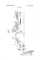
- FIG. 1 is a schematic view showing the overall arrangement of the principal components of our tubemaking apparatus.
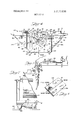
- FIG. 2 is a perspective view showing fabric being unwound and moved toward the folding means.
- FIG. 3 is a perspective view from in front of the folding means, looking from the roll of fabric toward the folding means and showing fabric moving around the elements of the folding means to form a tube.
- FIG. 4 is a front elevational view from behind the folding means, looking toward the roll of fabric and showing fabric moving around the elements of the folding means to form a tube.
- FIG. 5 is a side elevational view showing the tube moving over the extruder die which applies a hot melt adhesive to overlapping edges of the folded fabric.
- FIG. 6 is a perspective view showing a portion of the tube formed by our apparatus.
- FIG. 7 is an elevational view, with sections broken away, of the carriage which carries the roll of fabric.
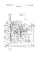
- FIG. 8 is a side elevational view of the drive system for our apparatus.
- FIG. 9 is a side elevational view of the drive system, with components deleted for clarity, showing the dancer roller in the raised position.
- FIG. 10 is a side elevational view of the drive system, with components deleted for clarity, showing the cutter in the down position severing the tube.
- FIG. 11 is a side elevational view, partially in section, showing the swatter arm which removes severed tubes from the conveyor.
- FIG. 12 is a plan view showing the conveyor which moves severed tubes from beneath the cutter.
- FIG. 1 The general arrangement of our tube-making apparatus 10 is schematically depicted in FIG. 1.
- the principal components of this apparatus are movable carriage 12 including spindle 13 on which roll 14 of fabric is rotatably mounted, folding means 16 between rollers 17 and 18, extruder including die 20 for applying a sealant such as a hot melt adhesive, a series of water-cooled chill rollers 21-23, primary drive rollers 24 and 25, dancer roller 26, idler roller 27, secondary drive rollers 28 and 29, cutter 30 and conveyor 32.
- a sealant such as a hot melt adhesive
- the fabric comprises woven, oriented, generally flat, warp and fill ribbon yarns made from polymeric materia1, preferably polypropylene.
- This fabric moves through apparatus 10 along the sinuous path indicated generally by arrows a, and as it moves around folding means 16 the fabric is folded so that the ends of the fill yarns along fabric edges 33 and 34 (FIGS. 2, 4 and 6) are brought into an overlapping position.
- Extruder die 20 applies a hot melt adhesive to overlapping edges 33 and 34 and chill rollers 21-23 next apply pressure to these overlapping edges to form the seam of a tube.
- FIG. 6 shows the folded, seamed material making up the tube.
- a heater 35 (FIGS. 2 and 5) may be provided to preheat the overlapping edges 33 and 34 prior to application of the adhesive.
- Primary drive rollers 24 and 25 and secondary drive rollers 28 and 29 move the seamed tube through apparatus 10 between cutter 30 and Teflon-covered platen roller 36 directly below blade 38 of cutter 30. Rollers 24 and 25 move continuously. Rollers 28 and 29 move intermittently. When secondary drive rollers 28 and 29 momentarily stop, cutter 30 lowers down on platen roller 36 to sever the tube into a predetermined length. With the cutting of the tube, a slack develops in the tube coming from primary drive rollers 24 and 25. This slack occurs because the tube is continuously advanced by rollers 24 and 25 while its forward portion is momentarily stopped and held by secondary drive rollers 28 and 29. Dancer roller 26 takes up this slack.
- a conventional Deitz scanner 40 including photocell 41 and light source 42, may be used to control the operation of rollers 28 and 29 and cutter 30 by reading registration marks printed on the fabric or, as we prefer, the operation of the rollers and cutter is controlled with or without the Deitz scanner by drive system 44 shown in FIGS. 8-10. This drive system 44 will be discussed later in detail.
- Conveyor 32 advances the severed tube to move between photocell 46 and light source 48 which straddle the tubes path.
- the severed tube interrupts the beam of light striking photocell 46 and this produces a signal which actuates swatter arm 50.
- Arm 50 pivots downwardly to free the tube from the grasp of conveyor 32, and the severed tube thus falls onto table 52. Periodically, the stack of severed tubes is removed from table 52 and further processed to make bags.
- carriage 12 is mounted to move to and fro generally transverse to the fabrics direction of travel.
- grooved casters 54 attached to base 56 of carriage 12 rests on tracks 58, and pneumatic piston 60 connected to the base of the carriage and a track serves to move the carriage.
- This piston 60 includes a pair of solenoids (not shown) which are actuated by a control circuit including photoelectric cell 62 and light source 63 which straddle the path of travel of the fabric.
- the fabric has essentially a constant width but it is not wrapped around spindle 13 uniformly.
- edge 33 is maintained at an essentially constant position relative to extruder die 20.
- the overlapping edges 33 and 34 are also maintained at a constant position relative to die 20. This insures that the adhesive is applied only along the overlapping edges 33 and 34, since the to and fro motion of carriage 12 always brings these edges into alignment with die 20.
- folding means 16 has three chief folding elements 66-68.
- the upper supports of these elements 66-68 include slots with bolts 69 passing through the slots and securing these elements to frame 11 of apparatus 10. This brings the three chief folding elements 66-68 into spaced relationship with each other. All are in different but proximate generally vertical planes, with element 67 between elements 66 and 68. By loosening the bolts and laterally sliding elements 66-68 into different positions, different widths of fabric can be folded.
- folding element 66 is the most intricate. It includes three sections 70, 80 and 90.
- Section 70 includes horizontal, slotted support 71 (FIG. 4) and tubular guide member 72 connected at its upper end 73 to support 71.
- Tubular guide member 72 lies in a generally vertical plane and is disposed at an angle of about 45 with respect to support 71.
- upper end 73 of member 72 is near fabric edge 33 and lower end 74 of member 72 is between fabric edge 33 and the central longitudinal axis of the fabric.
- Extending from end 74 is a generally horizontal stub 75 which lies along a line that is generally perpendicular to the longitudinal axis of the fabric.
- Brace 76 connects stub 75 to upper slotted support 71 and provides structural rigidity to section 70.
- Section 80 is virtually identical in construction to section 70, but is mounted on frame 11 of the apparatus so that sections 70 and 80 are in a leftand right-hand relationship, respectively, as viewed in FIG. 2.
- section 80 includes horizontal, slotted support 81 and tubular guide member 82 connected at its upper end 83 to slotted support 81.
- Tubular guide member 82 lies in a generally vertical plane and is disposed at an angle of about 45 with respect to support 81.
- upper end 83 of member 82 is near fabric edge 34
- lower end 84 of member 82 is between fabric edge 34 and the central longitudinal axis of the fabric.
- Extending from end 84 is a generally horizontal stub 85 which lies along a line that is generally perpendicular to the longitudinal axis of the fabric.
- Brace 86 connects stub 85 to upper slotted support 81 and provides structural rigidity to section 80.
- Sections 70 and 80 are in the same vertical plane and on the same side of the fabric. But, because they are arranged in a rightand left-hand relationship to each other, their respective guide members 72 and 82 slope toward each other so that their respective lower ends 74 and 84 are closer to each other than their respective upper ends 73 and 83.
- Section 90 is a tubular sleeve, also serving as a guide member, which is fitted over the opposing stubs 75 and 85.
- Section 90 is generally perpendicular to the fabric s longitudinal axis.
- FIG. 2 shows sections and 80 moved as close together as possible, with stubs and 85 almost touching while disposed within section 90 (FIG. 4). Since sections 70 and can be moved independently by loosening bolt 69 and moving these sections toward or away from each other, when these sections 70 and 80 are moved apart stubs 75 and slide within section and move away from each other.
- Folding element 67 includes horizontal, slotted support (FIG. 4) and tubular guide member 101 connected at its upper end 102 to support 100.
- Tubular guide member 101 lies in a generally vertical plane and is disposed at an angle of about 45 with respect to support 100.
- upper end 102 of member 101 is near fabric edge 33 and lower end 103 of member 101 is between fabric edge 33 and the central longitudinal axis of the fabric.
- integral with end 103 is vertical brace 104 which has an upper end 105 connected to support 100.
- Folding element 68 is somewhat similar in construction to folding element 67 but it is mounted on frame 11 so that element 68 and element 67 are in a leftand right-hand relationship, respectively, as viewed in FIG. 4.
- Element 68 includes an upper slotted support and tubular guide member 111. Instead of member 1 11 being connected directly to support 110, connecting rod 112, integral with upper end 113 of guide member 111, connects member 111 to support 110. Connecting rod 112 is generally horizontal and spaced from support 110 so that longitudinal edge 33 can move between this connecting rod and support 110. Integral with end 114 is vertical brace 115 which has an upper end 1 16 attached to support 1 10.
- folding elements 66-68 are attached to frame 11. Supports 71 and 81 of folding element 66 are attached to one side of frame 11, and supports 100 and 110 of folding elements 67 and 68 are attached to the opposite side of frame 11. This places the three folding elements 66-68 in three different, generally vertical planes, spaced apart but in close proximity to each other so that the fabric can wind about these elements as shown in FIGS. 2 through 5. As fabric moves along its predetermined path a, guide members 72 and 82 of folding element 66 are in advance of guide member 101 and guide member 111 of folding elements 67 and 68, respectively.
- folding elements 67 and 68 are arranged in a rightand lefthand relationship to each other, their respective guide members 101 and 111 slope toward each other so that their respective upper ends 102 and 113 crisscross. This crisscross brings longitudinal edges 33 and 34 into overlapping relationship as the fabric winds around elements 67 and 68.
- the fabric is manually fed around folding means 16. As best viewed in FIGS. 4 and 5, the leading edge of the fabric is drawn across roller 17, pulled downwardly until it reaches the lower portion of folding element 66, opposite member 90. Then the outer quarter-section 33a of the fabric adjacent edge 33 is tucked inwardly and wrapped around guide member 72, and the outer quarter-section 34a of the fabric adjacent edge 34 is tucked inwardly and wrapped around guide member 82. Next, the fabric is pulled over member 90 and drawn upwardly while wrapping outer quarter-section 33a around guide member 101 and wrapping outer quarter-section 34a around guide member 111. This brings edges 33 and 34 into overlapping relationship and as the fabric goes upwardly these overlapping edges straddle connecting rod 112.
- the fabric as it moves around folding means 16, first moves downwardly in a vertical direction with edges 33 and 34 being folded inwardly. As the fabric moves across folding element 66, it reverses its direction of travel and moves upwardly with quartersections 33a and 34a moving inwardly toward each other and the fabrics central longitudinal axis. Finally, as the fabric moves across folding elements 67 and 68, quarter-sections 33a and 34a change direction and move upwardly bringing edges 33 and 34 into overlapping, parallel positions. Thus the fabric is folded into tube form and the tube advances over roller 18 to the extruder.
- edge 33 of the tube is drawn over the top of extruder die 20 and edge 34 of the tube is drawn beneath the extruder die, locating the extruder die between overlapping edges 33 and 34.
- Adhesive is applied to edge 34 along a band corresponding essentially to the width of overlapping edge portions. As shown in FIG. 5, adhesive is applied to both edges 33 and 34. This, however, is optional.
- Chill rollers 21-23 immediately follow die 20 and they press the edges 33 and 34 together, insuring fixation of the adhesive to both edges.
- the adhesive on the edge surfaces flows through the openings in the weave and interlocks overlapping edges 33 and 34 together to form a seam.
- FIGS. 8-10 show dancer roller 26 mounted between the ends of two swinging arms. Only one arm 120 is shown in these figures. The other ends of these arms are pivotally mounted between a pair of stanchions. Stanchion 121 is shown wherein arm 120 is mounted at point 122. Also on arm 120 is a half-moon cam 123, secured to the arm so that as the arm swings up and down this cam 123 rotates clockwise and counterclockwise. The indent 123a of the cam strikes a limit switch 124 when the arm 120 is in an up position as shown in FIG. 9. In the down position of arm 120, the arm contacts limit switch 125. As will be discussed later, these switches 124 and 125 control the speed of drive motor 126.
- FIGS. 8 and show cutter 30 mounted on bar 127 which is pivotally mounted to frame 11a at point 128.
- Cam follower wheel 129 is also mounted to bar 127 between cutter 30 and point 128. This follower wheel 129 follows the cam edge of cam 130 secured to freewheeling shaft 132 mounted on frame 11a. As cam 130 revolves, cutter 30 is raised (FIG. 8) and lowered (FIG. 10).
- Cutter 30 includes heated blade 38 (preferably heated to about 950 F) whose leading edge 133a is angular and whose trailing edge 133b is vertical. This type of blade construction insures clean cutting of the tube.
- a Teflon-covered platen roller 36 Immediately below blade 38 is a Teflon-covered platen roller 36. Covering platen roller 36 with any suitable stick-resistant material prevents the severed tube from clinging to this roller 36.
- conveyor 32 includes two pairs of lateral conveyor belts and 142 which run along the length of the conveyor.
- the upper belts 140 are wound about rollers 144 and 146, and lower belts 142 are wound about rollers 148 and 150 (FIG. 11).
- a series of upper and lower conveyor belts extend about half the length of conveyor 32. These include upper belts 152 and 154 wound about rollers 156 and 158, and lower belts 160-162 wound about roller 148 and roller 164.
- Swatter arm 50 is pivotally attached to support member 166 and is actuated by solenoid (not shown). This solenoid is turned on when a severed tube moves between photocell 46 and light source 48 (FIG. 1). Swatter arm 50, which is between lateral conveyor belt 140, moves downwardly to strike the tube and direct it toward table 52.
- the drive system 44 shown in FIGS. 8 through 12 moves the tube through apparatus 10 continuously along the portion of path a prior to secondary drive rollers 28 and 29, and intermittently in a stop-start fashion subsequent to these secondary drive rollers.
- Primary drive rollers 24 and 25 are driven continuously but at a variable rate of speed through sprockets 1711-173 and chains 174 and 175.
- Motor 126 mounted to base frame 11b on the far side as viewed in FIG. 8, provides the motive force for primary drive rollers 24 and 25 and conveyor 32. It is a variable speed motor and includes a potentiometer control (not shown) including a resistor (not shown) which is switched into or out of circuit with the potentiometer to vary the speed. As will be explained in greater detail below, the actuation of switches 124 and 125 determines whether the resistor is in or out of circuit with the potentiometer.
- Sprocket 173 is connected to output shaft 180 of motor 126, and chain winds about this sprocket 173 and sprocket 172.
- Sprockets 172 and 171 are coupled to free-wheeling shaft 181 in stanchion 121.
- Sprocket 171 is a double sprocket, and chain 174 winds about one sprocket element of sprocket 171 and sprocket 170.
- output shaft 180 is transmitted to conveyor 32 through the other sprocket element of sprocket 171 and chain 182, and sprockets 183 and 184, attached, respectively, to the end rollers 158 and 164 (FIG. 12).
- Chain 182 winds about the other element of sprocket 171 and sprockets 183 and 184.
- Sprocket 185 provides tension for chain 182.
- Secondary drive rollers 28 and 29 are driven intermittently through sprockets -193, chains 194 and 195, slotted lever 196, arm 197, cam 130, sprockets 198 and 199, and chain 200.
- Constant speed motor 202 provides the motive force for secondary drive rollers 28 and 29.
- the drive for roller 29 is as follows: Sprocket 199 is connected to output shaft 203 of motor 202, and chain 200 winds around this sprocket 199 and sprocket 198.
- Cam 130 and sprocket 198 are secured to free-wheeling shaft 132.
- Ann 197 is pivotally attached to the face of cam 130 at one end and at its other end is secured to lever 196.
- Lever 196 includes slot 196a, and the lower end of arm 197 is bolted in position in the slot but can be moved within the slot to adjust the arc through which sprockets 190-193 move. Different lengths in the stroke of arm 197, as controlled by position of lower arm end, result in different lengths of severed tubes.
- Lever 196 is attached securely to free-wheeling shaft 193a of sprocket 193.
- This shaft 193a cyclically moves sprocket 193, clockwise and counter-clockwise, through an arc of about 60 asarm 197 pivots with the circular movement of cam 130.
- Chain 195 winds around sprocket 193 and sprocket 192, and chain 194 winds around sprocket 191 and sprocket 190.
- Sprocket 190 is attached to the shaft of roller 29 and sprockets 191 and 192 are attached to freewheeling shaft 191a in stanchion 121a.
- Roller 29 has clutch 210 (FIG. 12) at one end and brake 212 at the other end.
- Mounted on frame 110 are switches 214 and 216. Switch 214 controls clutch 210 and switch 216 controls brake 212, and cam 130 actuates these switches as cam edge periodically engages their contactors.
- constant speed motor 202 turns cam 130 which in turn raises and lowers cutter 30 and simultaneously drives the sprocket and chain assemblage turning the secondary drive rollers.
- arm 197 actuates lever 196 which in turn drives the train of sprockets 190193 and chains 194 and 195 clockwise and counter-clockwise through an are up to approximately 60.
- This turns shaft 29a of roller 29 (FIG. 12).
- the shaft 290 moves in a clockwise direction and then reverses itself and moves in a counter-clockwise direction.
- clutch 210 When shaft 29a is moving in a counter-clockwise direction (as viewed in FIG. 8), clutch 210 is actuated and the tube is advanced underneath raised cutter 30 and toward swatter arm 50.
- brake 212 When shaft 29a is moved in a clockwise direction brake 212 is actuated, holding the tube between the nip of secondary drive rollers 28 and 29. At this point cam 130 moves into a position such that a hot knife blade 133 lowers and abuts platen roller 36, severing the tube (FIG.
- Apparatus for making tubes from a roll of generally flat sheet material comprising means for unwinding the sheet material from the roll and for moving said unwound sheet material along a predetermined path,
- folding means including a. a first guide member at an angle of about 45 with respect to one longitudinal edge of the sheet material and having a first end near said one edge and a second end between said one edge and the central longitudinal axis of the sheet material;
- a second guide member at an angle of about 45 with respect to the other longitudinal edge of the sheet material and having a first end near said other edge and a second end between said other edge and the central longitudinal axis of the sheet material,
- first and second guide members being spaced apart but on the same side of the sheet material and sloping so that their second ends are further along the sheets path of travel than their first ends;
- a third guide member between and connected to the second ends of said first and second guide members and lying generally perpendicular to the central longitudinal axis of the sheet material;
- a fourth guide member at an angle of about 45 with respect to one longitudinal edge of the sheet material and having a first end near said one edge and a second end between said one edge and the central longitudinal axis of the sheet material;
- a fifth guide member at an angle of about 45 with respect to the other longitudinal edge of the sheet material and having a first end near said other edge and a second end between said other end and the central longitudinal axis of the sheet material,
- said fourth and fifth guide members being spaced apart, on the side of the sheet material opposite that of said first and second guide members and subsequent in the sheets path of travel to said first and second guide members, and sloping so that their first ends crisscross and are further along the sheets path of travel than their second ends,
- the sheet moving means includes first means which, along the forward portion of the path of the sheet material, move the sheet material continuously, and
- second means which, along the rearward portion of the path of the sheet material, move the sheet material intermittently.
- Apparatus for making tubes from a web of generally flat sheet material comprising means for moving the web of sheet material along a predetermined path,
- said folding means including a. a first guide member at an angle of about 45 with respect to one longitudinal edge of the sheet material having a first end near said one edge and a second end near the central longitudinal axis of the sheet material,
- a third guide member at an angle of about 45 with respect to said one edge of the sheet material having a first end near said one edge and a second end near the central longitudinal axis of the sheet material,
- said first and third guide members being spaced apart and on opposite sides of the sheet material and sloping opposite to each other,
- said apparatus additionally includes means for unwinding said roll
- the sheet moving means includes first means which, along the forward portion of the path of the sheet material, move the sheet material continuously, and
- second means which, along the rearward portion of the path of the sheet material, move the sheet material intermittently.
- an improved apparatus for making tubes from a roll of generally flat sheet material where unwound sheet material is folded so that its longitudinal edges overlap slightly and the sealing means apply at the overlapped edges a sealing material to form a seam along said edges the improvement comprising means for insuring that the overlapped edges are in alignment with the sealing means so that sealing material is applied at said overlapped edges, said means including means for unwinding the sheet material from the roll and for moving the unwound sheet material along a predetermined path past said sealing means, means for movably mounting the roll so that said roll can move to and fro generally transverse to the sheets direction of travel along said path, means connected to the movable mounting means for moving said roll to and fro, and means along said path which sense an edge of the unwound sheet material and, in response to a lateral change in position of the edge which would move overlapped edges out of alignment with the sealing means, which actuate the roll moving means to shift position of unwound sheet material so that the edge being sensed is returned to its original position bringing overlapped edges
Abstract
Disclosed is a method and apparatus for forming tubes from woven fabric, especially fabric made of polymeric ribbon yarns. The apparatus includes a movable carriage including a spindle on which a roll of the woven fabric is rotatably mounted. The fabric is unwound and passed over folding means which bring outer edges of the fabric into an overlapping position. An extruder applies a hot melt adhesive to the overlapping edges and then a series of chilled pressure rollers squeeze the overlapping edges together, cooling the adhesive and forming a seam. This fabricates a tube which is periodically severed into shorter lengths.
Description
United States Patent [191 McVay et al.
[ 51 Feb. 20, 1973 [54] TUBE-MAKING APPARATUS [75] lnventors: David Robert McVay, l-lazlehurst; Henry Louis Eickhoif, Dunwoody; Harry William Thatcher, Hazlehurst, all of Ga.
[52] US. Cl. ..156/463, 156/466, 156/547, 242/57.1, 93/8 R, 270/83 [51] Int. Cl. ..B29d 23/00 [58] Field of Search ..l56/199, 200, 202, 203, 204, 156/459, 461, 465, 466, 361, 463, 443, 448; 270/86, 93, 94; 93/8 R, 20; 242/723, 57.1
3,381,397 5/1968 Cohn et al. ..83/175 2,540,844 2/1951 Strauss ..270/93 2,660,219 11/1953 Haas et al ..l56/466 2,968,449 1/1961 Hajos ..242/57.1 3 ,222,005 12/ 1 965 Wendelken ..24 2/5 7 .1
Primary Examiner-Robert F. Burnett Assistant Examiner-R. .l. Roche Attorney-Arthur G. Gilkes, William T. McClain and John J. Connors 57 ABSTRACT Disclosed is a method and apparatus for forming tubes from woven fabric, especially fabric made of polymeric ribbon yarns. The apparatus includes a movable carriage including a spindle on which a roll of the woven fabric is rotatably mounted. The fabric is unwound and passed over folding means which bring outer edges of the fabric into an overlapping position. An extruder applies a hot melt adhesive to the overlapping edges and then a series of chilled pressure rollers squeeze the overlapping edges together, cooling the adhesive and forming a seam. This fabricates a tube which is periodically severed into shorter lengths.
10 Claims, 12 Drawing Figures PATENTEU 201973 SHEET 10? 6 INVENTORS. David Robert Mo l/ay Henry Louis E lck/mff Harry Will/am Thatcher ATTORNEY PATENTED FEB 2 01973 SHEET 2 u; 6
m r w w v. 7 n r 4 4 8 U PATENTED FEB 2 0 i973 SHEET 5 OF 6 PATENTEB FEBZOISH SHEE? 8 OF 6 TUBE-MAKING APPARATUS BACKGROUND Woven polymeric fabric is a strong, mildew-resistant material, and bags made of such fabric would be highly useful. However, this fabric is difficult to handle when making bags. For example, it is difficult to sew and requires large numbers of workers to produce a relatively small number of bags. The objective of our invention is to provide a method and apparatus which will automatically make from this fabric tubes that can be then readily made into bags. Our apparatus is highly efficient and reliable, as well as easy to maintain. The details of our method and apparatus are disclosed in the accompanying drawings and description.
DESCRIPTION OF DRAWINGS FIG. 1 is a schematic view showing the overall arrangement of the principal components of our tubemaking apparatus.
FIG. 2 is a perspective view showing fabric being unwound and moved toward the folding means.
FIG. 3 is a perspective view from in front of the folding means, looking from the roll of fabric toward the folding means and showing fabric moving around the elements of the folding means to form a tube.
FIG. 4 is a front elevational view from behind the folding means, looking toward the roll of fabric and showing fabric moving around the elements of the folding means to form a tube.
FIG. 5 is a side elevational view showing the tube moving over the extruder die which applies a hot melt adhesive to overlapping edges of the folded fabric.
FIG. 6 is a perspective view showing a portion of the tube formed by our apparatus.
FIG. 7 is an elevational view, with sections broken away, of the carriage which carries the roll of fabric.
FIG. 8 is a side elevational view of the drive system for our apparatus.
FIG. 9 is a side elevational view of the drive system, with components deleted for clarity, showing the dancer roller in the raised position.
FIG. 10 is a side elevational view of the drive system, with components deleted for clarity, showing the cutter in the down position severing the tube.
FIG. 11 is a side elevational view, partially in section, showing the swatter arm which removes severed tubes from the conveyor.
FIG. 12 is a plan view showing the conveyor which moves severed tubes from beneath the cutter.
PREFERRED EMBODIMENT In General The general arrangement of our tube-making apparatus 10 is schematically depicted in FIG. 1. The principal components of this apparatus are movable carriage 12 including spindle 13 on which roll 14 of fabric is rotatably mounted, folding means 16 between rollers 17 and 18, extruder including die 20 for applying a sealant such as a hot melt adhesive, a series of water-cooled chill rollers 21-23, primary drive rollers 24 and 25, dancer roller 26, idler roller 27, secondary drive rollers 28 and 29, cutter 30 and conveyor 32.
The fabric comprises woven, oriented, generally flat, warp and fill ribbon yarns made from polymeric materia1, preferably polypropylene. This fabric moves through apparatus 10 along the sinuous path indicated generally by arrows a, and as it moves around folding means 16 the fabric is folded so that the ends of the fill yarns along fabric edges 33 and 34 (FIGS. 2, 4 and 6) are brought into an overlapping position. Extruder die 20 applies a hot melt adhesive to overlapping edges 33 and 34 and chill rollers 21-23 next apply pressure to these overlapping edges to form the seam of a tube. FIG. 6 shows the folded, seamed material making up the tube. Optionally, a heater 35 (FIGS. 2 and 5) may be provided to preheat the overlapping edges 33 and 34 prior to application of the adhesive.
A conventional Deitz scanner 40, including photocell 41 and light source 42, may be used to control the operation of rollers 28 and 29 and cutter 30 by reading registration marks printed on the fabric or, as we prefer, the operation of the rollers and cutter is controlled with or without the Deitz scanner by drive system 44 shown in FIGS. 8-10. This drive system 44 will be discussed later in detail.
THE CARRIAGE To insure that the overlapping edges 33 and 34 are properly aligned with extruder die 20, carriage 12 is mounted to move to and fro generally transverse to the fabrics direction of travel. As best seen in FIGS. 2 and 7, grooved casters 54 attached to base 56 of carriage 12 rests on tracks 58, and pneumatic piston 60 connected to the base of the carriage and a track serves to move the carriage. This piston 60 includes a pair of solenoids (not shown) which are actuated by a control circuit including photoelectric cell 62 and light source 63 which straddle the path of travel of the fabric. When the beam of light striking photocell 62 is interrupted by fabric edge 33 (FIG. 3) as carriage 12 moves toward the left, as viewed in FIG. 3, a signal is generated which actuates one piston solenoid to move the carriage in the opposite direction, i.e., toward the right. When fabric edge 33 moves from between photocell 62 and light source 63, the beam of light once again strikes photocell 62. This generates a signal which actuates the other piston solenoid causing carriage 12 to return to the left. Thus carriage 12 continues to move to and fro as fabric is unwound from roll 14.
The fabric has essentially a constant width but it is not wrapped around spindle 13 uniformly. By sensing the lateral movement of fabric edge 33 and continually moving carriage 12 to and fro, edge 33 is maintained at an essentially constant position relative to extruder die 20. Thus, as the fabric moves around folding means 16, the overlapping edges 33 and 34 are also maintained at a constant position relative to die 20. This insures that the adhesive is applied only along the overlapping edges 33 and 34, since the to and fro motion of carriage 12 always brings these edges into alignment with die 20.
FOLDING MEANS As best shown in FIG. 2, folding means 16 has three chief folding elements 66-68. The upper supports of these elements 66-68 include slots with bolts 69 passing through the slots and securing these elements to frame 11 of apparatus 10. This brings the three chief folding elements 66-68 into spaced relationship with each other. All are in different but proximate generally vertical planes, with element 67 between elements 66 and 68. By loosening the bolts and laterally sliding elements 66-68 into different positions, different widths of fabric can be folded.
Of the three, folding element 66 is the most intricate. It includes three sections 70, 80 and 90. Section 70 includes horizontal, slotted support 71 (FIG. 4) and tubular guide member 72 connected at its upper end 73 to support 71. Tubular guide member 72 lies in a generally vertical plane and is disposed at an angle of about 45 with respect to support 71. As the fabric moves around member 72 (FIG. 4), upper end 73 of member 72 is near fabric edge 33 and lower end 74 of member 72 is between fabric edge 33 and the central longitudinal axis of the fabric. Extending from end 74 is a generally horizontal stub 75 which lies along a line that is generally perpendicular to the longitudinal axis of the fabric. Brace 76 connects stub 75 to upper slotted support 71 and provides structural rigidity to section 70.
Folding element 67 includes horizontal, slotted support (FIG. 4) and tubular guide member 101 connected at its upper end 102 to support 100. Tubular guide member 101 lies in a generally vertical plane and is disposed at an angle of about 45 with respect to support 100. As the fabric moves around member 101 (FIG. 4) upper end 102 of member 101 is near fabric edge 33 and lower end 103 of member 101 is between fabric edge 33 and the central longitudinal axis of the fabric. Integral with end 103 is vertical brace 104 which has an upper end 105 connected to support 100.
Folding element 68 is somewhat similar in construction to folding element 67 but it is mounted on frame 11 so that element 68 and element 67 are in a leftand right-hand relationship, respectively, as viewed in FIG. 4. Element 68 includes an upper slotted support and tubular guide member 111. Instead of member 1 11 being connected directly to support 110, connecting rod 112, integral with upper end 113 of guide member 111, connects member 111 to support 110. Connecting rod 112 is generally horizontal and spaced from support 110 so that longitudinal edge 33 can move between this connecting rod and support 110. Integral with end 114 is vertical brace 115 which has an upper end 1 16 attached to support 1 10.
As previously mentioned, all folding elements 66-68 are attached to frame 11. Supports 71 and 81 of folding element 66 are attached to one side of frame 11, and supports 100 and 110 of folding elements 67 and 68 are attached to the opposite side of frame 11. This places the three folding elements 66-68 in three different, generally vertical planes, spaced apart but in close proximity to each other so that the fabric can wind about these elements as shown in FIGS. 2 through 5. As fabric moves along its predetermined path a, guide members 72 and 82 of folding element 66 are in advance of guide member 101 and guide member 111 of folding elements 67 and 68, respectively. Because folding elements 67 and 68 are arranged in a rightand lefthand relationship to each other, their respective guide members 101 and 111 slope toward each other so that their respective upper ends 102 and 113 crisscross. This crisscross brings longitudinal edges 33 and 34 into overlapping relationship as the fabric winds around elements 67 and 68.
At start-up, the fabric is manually fed around folding means 16. As best viewed in FIGS. 4 and 5, the leading edge of the fabric is drawn across roller 17, pulled downwardly until it reaches the lower portion of folding element 66, opposite member 90. Then the outer quarter-section 33a of the fabric adjacent edge 33 is tucked inwardly and wrapped around guide member 72, and the outer quarter-section 34a of the fabric adjacent edge 34 is tucked inwardly and wrapped around guide member 82. Next, the fabric is pulled over member 90 and drawn upwardly while wrapping outer quarter-section 33a around guide member 101 and wrapping outer quarter-section 34a around guide member 111. This brings edges 33 and 34 into overlapping relationship and as the fabric goes upwardly these overlapping edges straddle connecting rod 112. Thus the fabric, as it moves around folding means 16, first moves downwardly in a vertical direction with edges 33 and 34 being folded inwardly. As the fabric moves across folding element 66, it reverses its direction of travel and moves upwardly with quartersections 33a and 34a moving inwardly toward each other and the fabrics central longitudinal axis. Finally, as the fabric moves across folding elements 67 and 68, quarter- sections 33a and 34a change direction and move upwardly bringing edges 33 and 34 into overlapping, parallel positions. Thus the fabric is folded into tube form and the tube advances over roller 18 to the extruder.
EXTRUDER In manually winding the fabric through apparatus 10, edge 33 of the tube is drawn over the top of extruder die 20 and edge 34 of the tube is drawn beneath the extruder die, locating the extruder die between overlapping edges 33 and 34. Adhesive is applied to edge 34 along a band corresponding essentially to the width of overlapping edge portions. As shown in FIG. 5, adhesive is applied to both edges 33 and 34. This, however, is optional. Chill rollers 21-23 immediately follow die 20 and they press the edges 33 and 34 together, insuring fixation of the adhesive to both edges. The adhesive on the edge surfaces flows through the openings in the weave and interlocks overlapping edges 33 and 34 together to form a seam.
DANCER ROLLER ASSEMBLY FIGS. 8-10 show dancer roller 26 mounted between the ends of two swinging arms. Only one arm 120 is shown in these figures. The other ends of these arms are pivotally mounted between a pair of stanchions. Stanchion 121 is shown wherein arm 120 is mounted at point 122. Also on arm 120 is a half-moon cam 123, secured to the arm so that as the arm swings up and down this cam 123 rotates clockwise and counterclockwise. The indent 123a of the cam strikes a limit switch 124 when the arm 120 is in an up position as shown in FIG. 9. In the down position of arm 120, the arm contacts limit switch 125. As will be discussed later, these switches 124 and 125 control the speed of drive motor 126.
CUTTER ASSEMBLY FIGS. 8 and show cutter 30 mounted on bar 127 which is pivotally mounted to frame 11a at point 128. Cam follower wheel 129 is also mounted to bar 127 between cutter 30 and point 128. This follower wheel 129 follows the cam edge of cam 130 secured to freewheeling shaft 132 mounted on frame 11a. As cam 130 revolves, cutter 30 is raised (FIG. 8) and lowered (FIG. 10).
CONVEYOR As best shown in FIGS. 11 and 12, conveyor 32 includes two pairs of lateral conveyor belts and 142 which run along the length of the conveyor. The upper belts 140 are wound about rollers 144 and 146, and lower belts 142 are wound about rollers 148 and 150 (FIG. 11). A series of upper and lower conveyor belts extend about half the length of conveyor 32. These include upper belts 152 and 154 wound about rollers 156 and 158, and lower belts 160-162 wound about roller 148 and roller 164. Swatter arm 50 is pivotally attached to support member 166 and is actuated by solenoid (not shown). This solenoid is turned on when a severed tube moves between photocell 46 and light source 48 (FIG. 1). Swatter arm 50, which is between lateral conveyor belt 140, moves downwardly to strike the tube and direct it toward table 52.
DRIVE SYSTEM The drive system 44 shown in FIGS. 8 through 12 moves the tube through apparatus 10 continuously along the portion of path a prior to secondary drive rollers 28 and 29, and intermittently in a stop-start fashion subsequent to these secondary drive rollers.
Drive for roller 25 and conveyor 32 is as follows: Sprocket 173 is connected to output shaft 180 of motor 126, and chain winds about this sprocket 173 and sprocket 172. Sprockets 172 and 171 are coupled to free-wheeling shaft 181 in stanchion 121. Sprocket 171 is a double sprocket, and chain 174 winds about one sprocket element of sprocket 171 and sprocket 170. Thus the rotational movement of the motors output shaft is transmitted through the sprocket and chain linkage to roller 25. The rotational movement of output shaft 180 is transmitted to conveyor 32 through the other sprocket element of sprocket 171 and chain 182, and sprockets 183 and 184, attached, respectively, to the end rollers 158 and 164 (FIG. 12). Chain 182 winds about the other element of sprocket 171 and sprockets 183 and 184. Sprocket 185 provides tension for chain 182.
The drive for roller 29 is as follows: Sprocket 199 is connected to output shaft 203 of motor 202, and chain 200 winds around this sprocket 199 and sprocket 198. Cam 130 and sprocket 198 are secured to free-wheeling shaft 132. Ann 197 is pivotally attached to the face of cam 130 at one end and at its other end is secured to lever 196. Lever 196 includes slot 196a, and the lower end of arm 197 is bolted in position in the slot but can be moved within the slot to adjust the arc through which sprockets 190-193 move. Different lengths in the stroke of arm 197, as controlled by position of lower arm end, result in different lengths of severed tubes. Lever 196 is attached securely to free-wheeling shaft 193a of sprocket 193. This shaft 193a cyclically moves sprocket 193, clockwise and counter-clockwise, through an arc of about 60 asarm 197 pivots with the circular movement of cam 130. Chain 195 winds around sprocket 193 and sprocket 192, and chain 194 winds around sprocket 191 and sprocket 190. Sprocket 190 is attached to the shaft of roller 29 and sprockets 191 and 192 are attached to freewheeling shaft 191a in stanchion 121a. Roller 29 has clutch 210 (FIG. 12) at one end and brake 212 at the other end. Mounted on frame 110 are switches 214 and 216. Switch 214 controls clutch 210 and switch 216 controls brake 212, and cam 130 actuates these switches as cam edge periodically engages their contactors.
In operation, as the seamed tube moves between primary drive rollers 24 and 25, winds about dancer and idler rollers 26 and 27, and moves into the nip of secondary drive rollers 28 and 29, constant speed motor 202 turns cam 130 which in turn raises and lowers cutter 30 and simultaneously drives the sprocket and chain assemblage turning the secondary drive rollers. Specifically, arm 197 actuates lever 196 which in turn drives the train of sprockets 190193 and chains 194 and 195 clockwise and counter-clockwise through an are up to approximately 60. This turns shaft 29a of roller 29 (FIG. 12). First, the shaft 290 moves in a clockwise direction and then reverses itself and moves in a counter-clockwise direction. When shaft 29a is moving in a counter-clockwise direction (as viewed in FIG. 8), clutch 210 is actuated and the tube is advanced underneath raised cutter 30 and toward swatter arm 50. When shaft 29a is moved in a clockwise direction brake 212 is actuated, holding the tube between the nip of secondary drive rollers 28 and 29. At this point cam 130 moves into a position such that a hot knife blade 133 lowers and abuts platen roller 36, severing the tube (FIG.
While secondary drive rollers 28 and 29 momentarily hold the tube stationary, primary drive rollers 24 and 25 continue feeding the tube. This causes a slack which dancer roller 26 takes up. If too great a slack develops in the tube, arm 120 swings down to contact switch 125. This switches the resistor into circuit with the potentiometer controlling the speed of motor 126. Motor 126 is slowed down and the rate at which the tube is fed by primary rollers 24 and 25 decreases. Thus the slack decreases, pulling the tube taut so dancer roller 26 moves up. Cam 123 on arm 120 begins to turn,-moving toward switch 124. When dancer roller 26 is carried upwardly beyond a predetermined point, this cam 123 strikes limit switch 124. This switches the resistor out of circuit with the potentiometer controlling motor 126, causing the speed of the motor to increase.
Thus slack again develops and dancer roller 26 moves downwardly. Cycling back and forth between lower and raised positions of dancer roller 26 takes up slack in the tube and leads to greater accuracy in the length of severed tubes.
Though our apparatus is described with specific reference to woven polymeric fabric, it could be used to make tubes from most generally flat sheet materials.
We claim: 1. Apparatus for making tubes from a roll of generally flat sheet material, comprising means for unwinding the sheet material from the roll and for moving said unwound sheet material along a predetermined path,
means for movably mounting the roll so that said roll can move to and fro generally transverse to the sheets direction of travel along said path,
means connected to the movable mounting means for moving said roll to and fro,
means along said path which sense an edge of the unwound sheet material and, in response to a lateral change in the position of the edge being sensed, actuate the roll moving means to return the edge to about its original position,
means along said path for folding said unwound sheet material so that its longitudinal edges overlap slightly, said folding means including a. a first guide member at an angle of about 45 with respect to one longitudinal edge of the sheet material and having a first end near said one edge and a second end between said one edge and the central longitudinal axis of the sheet material;
. a second guide member at an angle of about 45 with respect to the other longitudinal edge of the sheet material and having a first end near said other edge and a second end between said other edge and the central longitudinal axis of the sheet material,
said first and second guide members being spaced apart but on the same side of the sheet material and sloping so that their second ends are further along the sheets path of travel than their first ends;
c. a third guide member between and connected to the second ends of said first and second guide members and lying generally perpendicular to the central longitudinal axis of the sheet material;
. a fourth guide member at an angle of about 45 with respect to one longitudinal edge of the sheet material and having a first end near said one edge and a second end between said one edge and the central longitudinal axis of the sheet material; and
e. a fifth guide member at an angle of about 45 with respect to the other longitudinal edge of the sheet material and having a first end near said other edge and a second end between said other end and the central longitudinal axis of the sheet material,
said fourth and fifth guide members being spaced apart, on the side of the sheet material opposite that of said first and second guide members and subsequent in the sheets path of travel to said first and second guide members, and sloping so that their first ends crisscross and are further along the sheets path of travel than their second ends,
whereby said sheets direction of travel as it moves across said first and second guide members is changed to turn said edges inwardly to move toward the central longitudinal axis of the sheet material, and said sheets direction of travel as it moves across said third, fourth and fifth guide members is changed to bring the edges of the sheet into an overlapping position and to move said edges generally parallel to each other;
means along said path subsequent to the folding means for applying a sealing material to said overlapped edges and forming a seam along said overlapping edges, and
means along said path for cutting the folded and seamed sheet material along a line which is transverse to the sheets direction of travel along said path.
2. The apparatus of claim 1 wherein the sheet moving means includes first means which, along the forward portion of the path of the sheet material, move the sheet material continuously, and
second means which, along the rearward portion of the path of the sheet material, move the sheet material intermittently.
3. The apparatus of claim 2 wherein a slack in the sheet material is developed because of the continuous and intermittent motion of the sheet material, said apparatus additionally including means along said path which compensate for said slack.
4. The apparatus of claim 1 wherein said cutting means includes a heated knife blade.
5. Apparatus for making tubes from a web of generally flat sheet material, comprising means for moving the web of sheet material along a predetermined path,
means along said path for folding said sheet material so that its longitudinal edges overlap slightly, said folding means including a. a first guide member at an angle of about 45 with respect to one longitudinal edge of the sheet material having a first end near said one edge and a second end near the central longitudinal axis of the sheet material,
b. a second guide member connected to second end of said first guide member and lying generally perpendicular to the central longitudinal axis of the sheet material, and
c. a third guide member at an angle of about 45 with respect to said one edge of the sheet material having a first end near said one edge and a second end near the central longitudinal axis of the sheet material,
d. said first and third guide members being spaced apart and on opposite sides of the sheet material and sloping opposite to each other,
means along said path subsequent to the folding means for applyinga sealing material to said overlapped edges and ormmg-a seal along said over- 10 wound up as a roll, and said apparatus additionally includes means for unwinding said roll,
means for movably mounting said roll so that it can move to and fro generally transverse to the sheets direction of travel along said path,
means connected to said mounting means for moving said roll to and fro, and
means along said path which sense an edge of the unwound sheet material and, in response to the position of the edge being sensed, actuates the roll moving means.
7. The apparatus of claim 5 wherein the sheet moving means includes first means which, along the forward portion of the path of the sheet material, move the sheet material continuously, and
second means which, along the rearward portion of the path of the sheet material, move the sheet material intermittently.
8. The apparatus of claim 7 wherein a slack in the sheet material is developed because of the continuous and intermittent motion of the sheet material, said apparatus additionally including means along said path which compensate for said slack.
9. The apparatus of claim 5 wherein said cutting means includes a heated knife blade.
10. In an improved apparatus for making tubes from a roll of generally flat sheet material where unwound sheet material is folded so that its longitudinal edges overlap slightly and the sealing means apply at the overlapped edges a sealing material to form a seam along said edges, the improvement comprising means for insuring that the overlapped edges are in alignment with the sealing means so that sealing material is applied at said overlapped edges, said means including means for unwinding the sheet material from the roll and for moving the unwound sheet material along a predetermined path past said sealing means, means for movably mounting the roll so that said roll can move to and fro generally transverse to the sheets direction of travel along said path, means connected to the movable mounting means for moving said roll to and fro, and means along said path which sense an edge of the unwound sheet material and, in response to a lateral change in position of the edge which would move overlapped edges out of alignment with the sealing means, which actuate the roll moving means to shift position of unwound sheet material so that the edge being sensed is returned to its original position bringing overlapped edges into alignment with the sealing means.
Claims (9)
1. Apparatus for making tubes from a roll of generally flat sheet material, comprising means for unwinding the sheet material from the roll and for moving said unwound sheet material along a predetermined path, means for movably mounting the roll so that said roll can move to and fro generally transverse to the sheet''s direction of travel along said path, means connected to the movable mounting means for moving said roll to and fro, means along said path which sense an edge of the unwound sheet material and, in response to a lateral change in the position of the edge being sensed, actuate the roll moving means to return the edge to about its original position, means along said path for folding said unwound sheet material so that its longitudinal edges overlap slightly, said folding means including a. a first guide member at an angle of about 45* with respect to one longitudinal edge of the sheet material and having a first end near said one edge and a second end between said one edge and the central longitudinal axis of the sheet material; b. a second guide member at an angle of about 45* with respect to the other longitudinal edge of the sheet material and having a first end near said other edge and a second end between said other edge and the central longitudinal axis of the sheet material, said first and second guide members being spaced apart but on the same side of the sheet material and sloping so that their second ends are further along the sheet''s path of travel than their first ends; c. a third guide member between and connected to the second ends of said first and second guide members and lying generally perpendicular to the central longitudinal axis of the sheet material; d. a fourth guide member at an angle of about 45* with respect to one longitudinal edge of the sheet material and having a first end near said one edge and a second end between said one edge and the central longitudinal axis of the sheet material; and e. a fifth guide member at an angle of about 45* with respect to the other longitudinal edge of the sheet material and having a first end near said other edge and a second end between said other end and the central longitudinal axis of the sheet material, said fourth and fifth guide members being spaced apart, on the side of the sheet material opposite that of said first and second guide members and subsequent in the sheet''s path of travel to said first and second guide members, and sloping so that their first ends crisscross and are further along the sheet''s path of travel than their second ends, whereby said sheet''s direction of travel as it moves across said first and second guide members is changed to turn said edges inwardly to move toward the central Longitudinal axis of the sheet material, and said sheet''s direction of travel as it moves across said third, fourth and fifth guide members is changed to bring the edges of the sheet into an overlapping position and to move said edges generally parallel to each other; means along said path subsequent to the folding means for applying a sealing material to said overlapped edges and forming a seam along said overlapping edges, and means along said path for cutting the folded and seamed sheet material along a line which is transverse to the sheet''s direction of travel along said path.
2. The apparatus of claim 1 wherein the sheet moving means includes first means which, along the forward portion of the path of the sheet material, move the sheet material continuously, and second means which, along the rearward portion of the path of the sheet material, move the sheet material intermittently.
3. The apparatus of claim 2 wherein a slack in the sheet material is developed because of the continuous and intermittent motion of the sheet material, said apparatus additionally including means along said path which compensate for said slack.
4. The apparatus of claim 1 wherein said cutting means includes a heated knife blade.
5. Apparatus for making tubes from a web of generally flat sheet material, comprising means for moving the web of sheet material along a predetermined path, means along said path for folding said sheet material so that its longitudinal edges overlap slightly, said folding means including a. a first guide member at an angle of about 45* with respect to one longitudinal edge of the sheet material having a first end near said one edge and a second end near the central longitudinal axis of the sheet material, b. a second guide member connected to second end of said first guide member and lying generally perpendicular to the central longitudinal axis of the sheet material, and c. a third guide member at an angle of about 45* with respect to said one edge of the sheet material having a first end near said one edge and a second end near the central longitudinal axis of the sheet material, d. said first and third guide members being spaced apart and on opposite sides of the sheet material and sloping opposite to each other, means along said path subsequent to the folding means for applying a sealing material to said overlapped edges and forming a seal along said overlapping edges, and means along said path for cutting the folded and seamed sheet material along a line which is transverse to the sheet''s direction of travel along said path.
6. The apparatus of claim 2 wherein said web is wound up as a roll, and said apparatus additionally includes means for unwinding said roll, means for movably mounting said roll so that it can move to and fro generally transverse to the sheet''s direction of travel along said path, means connected to said mounting means for moving said roll to and fro, and means along said path which sense an edge of the unwound sheet material and, in response to the position of the edge being sensed, actuates the roll moving means.
7. The apparatus of claim 5 wherein the sheet moving means includes first means which, along the forward portion of the path of the sheet material, move the sheet material continuously, and second means which, along the rearward portion of the path of the sheet material, move the sheet material intermittently.
8. The apparatus of claim 7 wherein a slack in the sheet material is developed because of the continuous and intermittent motion of the sheet material, said apparatus additionally including means along said path which compensate for said slack.
9. The apparatus of claim 5 wherein said cutting means includes a heated knife blade.
Applications Claiming Priority (1)
| Application Number | Priority Date | Filing Date | Title |
|---|---|---|---|
| US9581670A | 1970-12-07 | 1970-12-07 |
Publications (1)
| Publication Number | Publication Date |
|---|---|
| US3717536A true US3717536A (en) | 1973-02-20 |
Family
ID=22253711
Family Applications (1)
| Application Number | Title | Priority Date | Filing Date |
|---|---|---|---|
| US00095816A Expired - Lifetime US3717536A (en) | 1970-12-07 | 1970-12-07 | Tube-making apparatus |
Country Status (1)
| Country | Link |
|---|---|
| US (1) | US3717536A (en) |
Cited By (8)
| Publication number | Priority date | Publication date | Assignee | Title |
|---|---|---|---|---|
| US4011708A (en) * | 1974-11-26 | 1977-03-15 | Packaging Industries, Inc. | Bag handling apparatus |
| US4124424A (en) * | 1976-12-08 | 1978-11-07 | Automated Components Inc. | Method and apparatus for maintaining fabric folds and shapes during manufacture of a fabric product |
| US4170504A (en) * | 1974-10-21 | 1979-10-09 | The Goodyear Tire & Rubber Company | Tire building accessory |
| FR2501108A1 (en) * | 1981-03-09 | 1982-09-10 | Riego Nuevas Tecnicas | PROCESS FOR MANUFACTURING PIPES FOR IRRIGATION AND OTHER USES |
| US4540392A (en) * | 1983-12-23 | 1985-09-10 | International Paper Company | Method and apparatus to seal coated paperboard materials |
| US20110005456A1 (en) * | 2008-03-12 | 2011-01-13 | Ideko, S. Coop. | Head for the automatic positioning of fibre blankets |
| EP2383379A1 (en) * | 2010-04-29 | 2011-11-02 | Pugi Group S.r.L. | Folding apparatus for textile machines |
| CN102802918A (en) * | 2009-08-07 | 2012-11-28 | 莫罗·文森索·博内利 | Method and apparatus for manufacturing a semifinished product for tubular labels |
Citations (9)
| Publication number | Priority date | Publication date | Assignee | Title |
|---|---|---|---|---|
| US2540844A (en) * | 1947-11-28 | 1951-02-06 | Allis Chalmers Mfg Co | Web folding machine |
| US2660219A (en) * | 1950-03-15 | 1953-11-24 | Interstate Folding Box Co | Heat-sealing machine |
| US2673495A (en) * | 1946-03-13 | 1954-03-30 | Continental Can Co | Method and apparatus for making bags |
| US2968449A (en) * | 1954-06-09 | 1961-01-17 | Premier Laundry Inc | Machine for rolling towels |
| US3082715A (en) * | 1960-03-15 | 1963-03-26 | Cocker Machine & Foundry Compa | Cloth folding and stitching device |
| US3222005A (en) * | 1963-12-13 | 1965-12-07 | Cutting Room Appliances Corp | Edge alignment device for cloth laying machines |
| US3345965A (en) * | 1965-04-01 | 1967-10-10 | Riegcl Textile Corp | Apparatus for producing prefolded diapers |
| US3381397A (en) * | 1965-11-19 | 1968-05-07 | Samcoe Holding Corp | Method and means for converting tubular knitted fabric to open width |
| US3557156A (en) * | 1968-02-05 | 1971-01-19 | Int Paper Co | Sectional drive apparatus for continuously feeding an elastic material |
-
1970
- 1970-12-07 US US00095816A patent/US3717536A/en not_active Expired - Lifetime
Patent Citations (9)
| Publication number | Priority date | Publication date | Assignee | Title |
|---|---|---|---|---|
| US2673495A (en) * | 1946-03-13 | 1954-03-30 | Continental Can Co | Method and apparatus for making bags |
| US2540844A (en) * | 1947-11-28 | 1951-02-06 | Allis Chalmers Mfg Co | Web folding machine |
| US2660219A (en) * | 1950-03-15 | 1953-11-24 | Interstate Folding Box Co | Heat-sealing machine |
| US2968449A (en) * | 1954-06-09 | 1961-01-17 | Premier Laundry Inc | Machine for rolling towels |
| US3082715A (en) * | 1960-03-15 | 1963-03-26 | Cocker Machine & Foundry Compa | Cloth folding and stitching device |
| US3222005A (en) * | 1963-12-13 | 1965-12-07 | Cutting Room Appliances Corp | Edge alignment device for cloth laying machines |
| US3345965A (en) * | 1965-04-01 | 1967-10-10 | Riegcl Textile Corp | Apparatus for producing prefolded diapers |
| US3381397A (en) * | 1965-11-19 | 1968-05-07 | Samcoe Holding Corp | Method and means for converting tubular knitted fabric to open width |
| US3557156A (en) * | 1968-02-05 | 1971-01-19 | Int Paper Co | Sectional drive apparatus for continuously feeding an elastic material |
Cited By (10)
| Publication number | Priority date | Publication date | Assignee | Title |
|---|---|---|---|---|
| US4170504A (en) * | 1974-10-21 | 1979-10-09 | The Goodyear Tire & Rubber Company | Tire building accessory |
| US4011708A (en) * | 1974-11-26 | 1977-03-15 | Packaging Industries, Inc. | Bag handling apparatus |
| US4124424A (en) * | 1976-12-08 | 1978-11-07 | Automated Components Inc. | Method and apparatus for maintaining fabric folds and shapes during manufacture of a fabric product |
| FR2501108A1 (en) * | 1981-03-09 | 1982-09-10 | Riego Nuevas Tecnicas | PROCESS FOR MANUFACTURING PIPES FOR IRRIGATION AND OTHER USES |
| US4540392A (en) * | 1983-12-23 | 1985-09-10 | International Paper Company | Method and apparatus to seal coated paperboard materials |
| US20110005456A1 (en) * | 2008-03-12 | 2011-01-13 | Ideko, S. Coop. | Head for the automatic positioning of fibre blankets |
| US8408266B2 (en) * | 2008-03-12 | 2013-04-02 | Ideko S. Coop. | Head for the automatic positioning of fibre blankets |
| CN102802918A (en) * | 2009-08-07 | 2012-11-28 | 莫罗·文森索·博内利 | Method and apparatus for manufacturing a semifinished product for tubular labels |
| EP2383379A1 (en) * | 2010-04-29 | 2011-11-02 | Pugi Group S.r.L. | Folding apparatus for textile machines |
| WO2011135500A1 (en) * | 2010-04-29 | 2011-11-03 | Pugi Group S.R.L. | Folding apparatus for textile machines. |
Similar Documents
| Publication | Publication Date | Title |
|---|---|---|
| US2897729A (en) | Apparatus for the manufacture of draw cord bags | |
| US2815620A (en) | Manufacture of packages with detachable registered printed appendages | |
| US4003298A (en) | Apparatus for driving moving webs in bag making machines | |
| US3257256A (en) | Device for welding and cutting thermoplastic webs | |
| US4333790A (en) | Rotary bag sealing and perforating machine | |
| US4489900A (en) | Apparatus for automatically cutting and winding sheet material | |
| EP0405595B1 (en) | A machine for continuous manufacturing of netting bags | |
| US20040128957A1 (en) | Automatic high speed wrapping machine | |
| US3650449A (en) | Intermittent feeding apparatus for a web of paper or plastics material | |
| US3717536A (en) | Tube-making apparatus | |
| US3722376A (en) | Bag machine | |
| GB1384570A (en) | Method and machine for making thermoplastic bags | |
| US3992981A (en) | Web stripping apparatus | |
| US3383268A (en) | Flaw detector | |
| US4954206A (en) | Welding apparatus for welding plastic web including tensioned strips of polytetrafluoroethylene | |
| US3853664A (en) | Bag making machine and method | |
| US4318340A (en) | Variable tape advance imprint marker | |
| US4313781A (en) | Method and apparatus for cutting and sealing thermoplastic material | |
| US4798576A (en) | Bag making machine | |
| US4065344A (en) | Bag forming method and apparatus | |
| US3650873A (en) | Bag making machine having heat sealer whose dwell time is adjustable | |
| US2465044A (en) | Apparatus for making bags | |
| US3713940A (en) | Method for securing handles to sheet material | |
| US3400033A (en) | Machine for internal applications and machining in an endless tubular article made up of a thermoplastic material or the like | |
| US3340776A (en) | Packaging machine |