US3741663A - Hole detector (for moving web) - Google Patents
Hole detector (for moving web) Download PDFInfo
- Publication number
- US3741663A US3741663A US00238291A US3741663DA US3741663A US 3741663 A US3741663 A US 3741663A US 00238291 A US00238291 A US 00238291A US 3741663D A US3741663D A US 3741663DA US 3741663 A US3741663 A US 3741663A
- Authority
- US
- United States
- Prior art keywords
- web
- trough
- light
- sensors
- hole
- Prior art date
- Legal status (The legal status is an assumption and is not a legal conclusion. Google has not performed a legal analysis and makes no representation as to the accuracy of the status listed.)
- Expired - Lifetime
Links
Images
Classifications
-
- G—PHYSICS
- G01—MEASURING; TESTING
- G01N—INVESTIGATING OR ANALYSING MATERIALS BY DETERMINING THEIR CHEMICAL OR PHYSICAL PROPERTIES
- G01N21/00—Investigating or analysing materials by the use of optical means, i.e. using sub-millimetre waves, infrared, visible or ultraviolet light
- G01N21/84—Systems specially adapted for particular applications
- G01N21/88—Investigating the presence of flaws or contamination
- G01N21/89—Investigating the presence of flaws or contamination in moving material, e.g. running paper or textiles
- G01N21/892—Investigating the presence of flaws or contamination in moving material, e.g. running paper or textiles characterised by the flaw, defect or object feature examined
- G01N21/894—Pinholes
Definitions
- ABSTRACT A hole detector for a moving web of translucent or opaque material capable of indicating the presence of lune 26, 1973 relatively small holes at high web speeds.
- An elongate light source and light sensing trough are spaced on opposite sides of the moving web and extend transversely across the portion of the web to be monitored.
- Light sensors are spaced along the bottom wall of the trough remote from the web for receiving direct light inputs through web holes passing over the open top of the trough.
- the light sensors are nonresponsive to spurious light inputs and each sensor responds negligibly, at most, to passage of a web hole over neighboring sensors, while permitting a space to be maintained between the web and the trough to prevent abrasion damage to the web being monitored despite normal flexing of the web.
- the trough depth substantially exceeds its width.
- the sidewalls of the trough diverge at a very shallow included angle from a bottom wall and terminate in shorter, parallel upper sidewalls.
- the sensors are separately compartmented within the trough, the walls of each compartment being substantially fully light absorptive.
- the trough has externally extending flanges at the top thereof for preventing light reflected from the undersurface of the web from reaching the sensors.
- the device is adapted to handle webs of decreased widths and includes devices for indicating the presence and locations of holes in the web.
- the present invention was developed in connection with hole detection in webs in the paper making industry, more particularly for detecting holes in paper of various types including so-called board and particularly for use within the paper or board machine producing the web.
- a number of special problems arise in connection with hole detection in paper webs. Among these are the fact that such webs are normally light or white in color and have a substantial capacity for reflecting light. Further, paper particularly of thinner grades, may have a relatively high translucency, or lighttransmitting capability, in unholed portions thereof. Further, paper and board machines are typically operated in areas having relating high ambient lighting to facilitate visual inspection of the paper as it moves through the paper machine and, to enable the usual manual threading of the machine and to enable machine adjustments and maintenance.
- Optical hole detectors have been known for a number of years, particularly those wherein a web to be monitored for holes is moved between a light source and a light sensor.
- many of these prior art devices are not fully satisfactory for use in hole detection in connection with paper or paper board webs, failing to satisfactorily meet problems such as those above stated.
- many of the prior art hole detection devices are of substantial structural complexity and have been found to be excessively costly, particularly in smaller or marginal mills wherein the purchase and installation cost may be prohibitive.
- many mills exist wherein hole detection is either omitted or carried out manually, by visual inspection, the latter being both unreliable and costly over a long period of time.
- the objects of this invention include provision of:
- a hole detector for a moving web which responds with substantial sensitivity to direct light inputs through holes in a web moving therepast but which is substantially unaffected by direct or reflected light inputs from other sources.
- An apparatus having a low optical noise level, i.e., being capable of detecting relatively small holes in relatively rapidly moving webs.
- An apparatus as aforesaid, particularly adapted to detection of holes in a paper, or paper board, web moving through a paper machine during the process of manufacture of such web.
- An apparatus as aforesaid, which is compact and capable of being interfitted between close spaced portions of a paper machine.
- An apparatus as aforesaid, which may be readily adjusted in position to meet requirements of a variety of web positions and angles and/or to facilitate maintenance thereof and of the paper machine as well as threading of the ladder.
- An apparatus capable of indicating with high reliability the part of the web in which a hole has occurred and wherein passage of a hole in the web therepast will actuate one sensor of the apparatus while having, at most, a negligible effect on others.
- An apparatus as aforesaid, readily adaptable to decreasing web widths without degradation of performance.
- An apparatus capable of indicating a hole condition in any of several ways to enable paper machine operators to note and/or eliminate damaged portions of the paper web.
- An apparatus as aforesaid, constructable and saleable at a low cost and which is of substantial structural simplicity and capable of operation over long periods of time without degradation of operation.
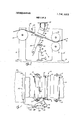
- FIG. 1 is a partially broken fragmentary view of a paper machine with the apparatus embodying the invention installed in operating position with respect to a moving web.
- FIG. 2 is a fragmentary side elevational view of the apparatus of FIG. 1.
- FIG. 3 is an enlarged, central cross sectional view of the trough of FIG. 2.
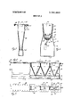
- FIG. 4 is a partially broken, fragmentary side elevational view, in reduced scale, of the trough of FIG. 3.
- FIG. 5 is a fragmentary partially broken top view of the trough of FIG. 4.
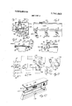
- FIG. 6 is an enlarged portion of the trough of FIG. 3 showing a light sensor in exploded relation to it.
- FIG. 7 is an enlarged, central cross sectional view of a marking device shown in FIG. 2.
- FIG. 8 is a fragmentary sectional view substantially as taken on the line VIII-VIII of FIG. 7.
- FIG. 9 is a partially broken, fragmentary end view of the trough of FIG. 3 with an edge light shield installed thereon.
- FIG. 10 is a fragmentary, side elevational view of the apparatus of FIG. 9.
- FIG. 11 is a schematic diagram of a portion of the electrical circuitry associated with the apparatus of FIG. 1.
- FIG. 12 is a'fragmentary, partially broken pictorial view of the trough of FIG. 2 disclosing a modified mounting therefor.
- a hole detector for a moving web of translucent or opaque material capable of indicating the presence of relatively small holes at high web speeds.
- An elongate light source and light sensing trough are spaced on opposite sides of a moving web and extend transversely across the portion of the web to be monitored.
- Light sensors are spaced along the bottom wall of the trough remote from the web for receiving direct light inputs through web holes passing over the open top of the trough.
- the light sensors are made nonresponsive to other potential light inputs and each sensor responds negligibly, at most, to passage of a web hole over neighboring sensors while permitting a space to be maintained between the web and the trough to prevent abrasion damage to the web being monitored despite normal flexing of the web.
- the trough depth substantially exceeds its width.
- the sidewalls of the trough diverge at a very shallow included angle from the bottom wall and terminate in shorter, parallel upper sidewalls.
- the sensors are separately compartmented within the trough, the walls of each compartment being substantially fully light absorptive.
- the trough has externally extending flanges at the top thereof for preventing light reflected from the undersurface of the web from reaching the sensors.
- the device is adapted to handle webs of decreased widths and includes devices for indicating the presence and locations of holes in the web.
- the apparatus embodying the invention is shown, for purposes of illustration, installed between roll supports 12 and 13 upstanding from the floor 14, in a conventional paper machine.
- the support 12 carries rolls l6 and 17 between the nip of which leftwardly passes a web 18 to be monitored for holes.
- the web 18 moves from the rolls l6 and 17 past the apparatus 10 and thence over a roll 21 carried by the support 13 toward the output end of the paper machine.
- the apparatus 10 was developed primarily for use in hole detection in rapidly moving paper or paper board webs and will be described herein in connection with such use, though it is contemplated that at least in certain instances the apparatus 10 is readily adapted to use with other types of moving webs for hole detection.
- the apparatus 10 may be used at a number of locations along the length of a paper machine, particularly following the fourdrinier section. A useful and convenient location for the apparatus 10 is, however, at the output of the drier section of the paper machine and ahead of the output section 22 of the machine.
- the output section 22 may, for example, consist of a reeling section for producing paper rolls, a sheet cutting section for producing stacks of sheets of predetermined size, a coater, etc. and a machine operator is normally stationed thereat.
- the apparatus 10 may also be used at locations remote from the paper machine, for example, in a separate coating or reeling machine.
- the apparatus 10 embodying the invention comprises a light source 23, a hole detector unit 24, and an output unit 26.
- the light source 23 and detector unit 24 are disposed on opposite sides of the web 18 and are aligned transversely thereof.
- the apparatus 10 is most conveniently installed with the light source 23 located above the web and the detector unit 24 located below the web, although the apparatus 10 will function with the units 23 and 24 in reverse location.
- the web 18 is sloped.
- the apparatus 10 is also usable with webs extending horizontally or vertically.
- the light source 23 here comprises a generally rectangular housing 28 which extends transversely across the web 18, preferably the full width thereof.
- the housing may be of any convenient construction, sheet metal being preferred and is preferably closed on all sides except the side 29 which faces the web and is normally spaced therefrom by a distance of several inches.
- the housing 28 contains a source of light (not shown) of any conventional nature, for example a spaced series of flood lamps.
- the light source is supplied electrical current normally from a conventional volt AC source (not shown) through the cable 31.
- the light source 23 may be supported above the web by any convenient means, here through adjustable length chains 32 dependent from a catwalk 33 of the paper machine.
- the apparatus 10 has a relatively low light input requirement. Thus, where relatively large holes, for example above an inch in diameter, are to be detected in a substantially opaque, low reflectivity web and a relatively high ambient light level is maintained in the region of the paper machine occupied by the apparatus 10, the light source 23 may be omitted.
- the hole detector unit 24 (FIGS. 2-6) comprises an elongate trough or light sensor housing 36.
- the trough 36 is described below in its upright position of FIGS. 2-5, though in use it may be oriented as desired.
- the trough 36 in length, extends the width of, and preferably beyond the edges of, the web 18 and, in depth, preferably extends per pendicularly away from the web.
- the top of the trough is preferably parallel to the web and close spaced therefrom, normally by a dimension in the range of one half to 2 inches, frequently about an inch.
- the spacing of the trough 36 from the web depends upon the normal deviation of the web from its mean path during operation of the machine, and is selected to prevent contact between the trough and web, to avoid damage to the relatively delicate surface of the web.
- the width of the trough is small compared to the depth thereof as hereinafter discussed.
- the trough 36 is of compact cross section to enable same to fit between close spaced adjacent web carrying units of the paper machine.
- the trough 36 (FIG. 3) comprises a pair of upstanding, spaced and parallel upper sidewalls 37.
- Coplanar flanges 39 extend outwardly from the upper edges of the upper sidewalls 37 and terminate at their outermost edge extremities in a roll, here provided by welding of suitable tubing 41 or the like thereto, to protect operating personnel moving therepast from injury by contact with such flanges 39.
- Integrally and downwardly extending from each of the upper sidewalls 37 are lower sidewalls 43 of depth substantially exceeding that of the upper sidewalls 37.
- the lower sidewalls 43 converge very gradually, here at approximately 12 included angle, to a connecting, preferably integral bottom wall 45.
- the upper sidewall 37 and lower sidewalls 43 are, respectively, 4 and 8 inches in depth, the upper sidewalls are spaced at approximately 3 inches and the width of the bottom wall 45 is approximately 1 k inches.
- the trough is deep relative to its width, tapers for most of its length and is of compact cross-section compared, for example, to the normal width of paper webs, e.g. 200 inches.
- Upstanding end walls 46 close the ends of the trough.
- the end walls 46 have outwardly extending flanges 48 and tubing elements 49 in the manner above described with respect to the sidewalls.
- a plurality of barriers 50 are evenly spaced along the length of the trough 36 and extend between, and preferably to the height of, the sidewalls.
- the barriers divide the trough into upwardly opening compartments 52.
- Each of the barriers 50 comprises a pair of downwardly diverging, frusto-triangular lower barrier walls 54 (FIGS. 4 and 5) which extend between the lower sidewalls 43 to the bottom wall 45 and an upstanding upper barrier wall 51 which is preferably an upward continuation of one of the sloped lower barrier walls 54.
- the length of the compartments 52 is determined by the number of sensing compartments 52 desired for a given width of web and a dimension in the range of 6 to 24 inches is contemplated, the length and the par ticular embodiment shown being approximately 9 inches.
- the upper and lower barrier walls 51 and 54 are fixed within the trough by any convenient means, here by integral flanges 56 secured, for example, by screws, riveting, welding, etc., to the widewalls of the trough.
- Each of the compartments 52 so formed is lighttight except for the open upper end thereof and for a central sensor mounting hole 57 (FIGS. 5 and 6) in the bottom wall 45.
- each compartment 52 are fully covered, e.g. coated or lined, with a suitable material which is highly light absorptive.
- a suitable material which is highly light absorptive.
- a layer of black felt 58 is cemented to and covers the walls 37, 43, 51 and 54 within each compartment.
- the light absorptive lining is omitted in FIGS. 4 and 5 from the rightwardmost compartment 52A only to illustrate more clearly the construction and interconnection of the sidewalls and barriers thereof.
- the compartment 52A would in use be lined in the manner above described with respect to the remaining ones of the compartments 52 shown.
- a suitable sensor mounting socket 60 (FIG. 6) is provided in the bottom of each compartment 52 and here comprises a socket member 61 which extends downwardly through the opening 57 in the bottom wall 45 and is fixed in place by a nut 62.
- the socket 60 receives a light sensor 64 with the light input surface thereof facing upwardly from the bottom of the compartment 52.
- the light sensor 64 is of the cadmium sulfide type, Model No. CL603 manufactured by Clairex Electronics, Inc. of New York, NY. and which provides a light to dark resistance ratio of l:l0,000.
- a cable housing 71 extends the length of the trough 36 for supporting and protecting the cable 67.
- the cable housing 71 is compact and in the particular embodiment shown comprises a bottom wall 72 and upstanding sidewalls 73 which terminate in upwardly flared edge portions 74.
- the edge portions overlap the lower trough sidewalls 43 and are preferably releasably secured thereto by screws 76'located between the compartments 52.
- the cable housing 71 may be of strictly rectangular cross-section, except for the flared edge portions 74,
- the cable housing has closed end walls 78 which overlap the trough end walls 46, one of such cable housing end walls 78 being pierced and having a fitting 79 for admitting the cable 67 therethrough.
- the upper end of the trough 36, and hence the upper ends of the compartments 52, are closed by a transparent plate 81, for example a sheet of rigid plastic, which extends across the tops of the upper barriers 51 and is supported upon the upper faces of the joined side and end flanges 39 and 48.
- the edges of the sheet 81 are removably secured to the flanges by spaced screws 82 to seal the compartments 52 against incursions of foreign material, particularly paper dust, which might impair the sensitivity of the sensor 64 and the light absorbency of the lining 58.
- the transparent plate 81 also serves to protect the interior of the trough from mechanical damage and incursions of water or other liquids (as when the apparatus 10 is used near the wet end of a paper machine or in a coating apparatus).
- a support device 86 (FIG. 2) supports the trough 36 above the floor 14, to allow movement of the trough 36 downwardly away from the web to facilitate threading of the web 18 through the paper machine as well as to allow access to the interior of the trough 36, for example for changing the sensors 64.
- the support device 86 here comprises a plurality of fluid operated jack 87 having upstanding reciprocable piston rods 88 spaced along the length of the trough. Each rod 88 terminates in a bracket 89 including a portion 91 fixed as by welding to the adjacent lower sidewall of the trough 36.
- the jacks 87 may be remotely operated through control of a fluid pressure supply (not shown) connected to a sup ply line 92.
- a light shield 96 (FIGS. 9 and 10) is appliable to the trough 36 when webs of width less than the length of such trough are to be monitored for holes so as to prevent against spurious light inputs to the endmost compartments of the trough.
- the light shield 96 is preferably formed of sheet metal and comprises a base 98 of substantially C-shaped cross-section which is snugly slidable over and along the upper end of the trough surrounding the flanges 39 and tubes 49 and overlying the transparent plate 81.
- the base 98 comprises a central platelike portion 99 which lies atop the transparent plate 81 and preferably contacts same with a nonabrasive surface (not shown) such as a felt pad.
- each interconnected flange 101 and flange extension 102 is separated from the remainder thereof by cuts 104 extending from the free edges of the respective flange extension 102, the intermediate portions 103 being formed to more snugly grip the tubing 104 and provide resistance to unintentional sliding displacement of the shield 96 along the length of the trough and thereby hold same in place on such trough.
- a shield flange Angled upwardly and outwardly from the inner edge of the central portion 99 is a shield flange which terminates at its upper end in a substantially horizontally inwardly extending top shield 107 integral therewith.
- the side edges 108 of the shield flange 106 diverge upwardly, the corresponding side edges of the top shield preferably extending substantially in parallellism therefrom and thereby overhanging the transparent plate 81 and flanges 39.
- the light shield 96 is normally placed on the trough so that the leftward (as seen in FIG.
- the inner faces (those defining the pocket 111) of the shield flange 106 and top shield 107 are preferably lined or coated with a light absorbing material such as black felt to prevent reflection of light striking same into the interior of the trough.
- the output unit 26 includes a plurality, preferably one per sensor, of amplifiers 116 which are adjustable for gain and operated from a conventional electrical source not shown.
- the amplifiers are located in a housing 117. If desired the housing 117 may be located remotely of the paper machine and hole detector unit 24. System operations have been conducted with amplifier housing 117 located as much as 25 feet away from the detector unit 24.
- the amplifiers 116 include means for providing operating current through the corresponding one of said photoresistors and for monitoring the resistance thereof to an output voltage which changes in relation to resistance change in the photoresistor and thereby in relation to the light input thereto.
- Output from each of the amplifiers 116 is applied through a line 119 (FIG. 11) to a corresponding one of a plurality of control circuits 120, one thereof being shown within the broken line box in FIG. 11.
- the control circuits 120 are preferably identical and only one such control circuit need be shown.
- the control circuit 120 includes a master relay 122 actuated by an output on line 119, indicating detection of a hole by the corresponding sensor 64.
- the minimum hole size required for actuation of the relay 122 is controlled by a conventional gain control (not shown) in the amplifier 116.
- the relay 122 has a normally open contact 123 connected to an operating potential supply line 124, connected to a suitable electrical power source (not shown).
- the contact 123 when closed connects the supply line 124 to an output line 126.
- One such output line 126 connects from each of the several circuits 120 to corresponding inputs of a logical OR function device 127.
- the OR gate 127 When actuated, the OR gate 127 provides an output on a line 128 to a generalized, or all system, detection indication device 130.
- the all system indicator 130 is a chart recorded which includes a solenoid 131 which mechanically drives, as indicated at 132, a stylus 133 across a chart 134 to record, for example over the period of one working shift, the totality of holes detected by the apparatus embodying the invention.
- Each control circuit further includes, connected in series between the relay contact 123 and the ground side 136 of the power supply (not shown) connected to the supply line 124, a series line comprising a holding relay 137 and a normally closed lamp de-energizing switch 138. Connected in series from the potential line 124 to the ground line 136 are a normally open contact 139 of holding relay 137 and a holding warning lamp 141.
- the lamps 141 associated with each of the sensors 64 are preferably supported by a lamp housing 143 (FIG. 1) adjacent the paper machine output device 22 and above the particular segment of the web 18 which traverses the compartment associated with the corresponding sensor 64 for warning operating personnel located at the paper machine output device 22 that a hole has been detected in a given part of the web and will soon arrive at the output device 22.
- the lamp deactuating switch 138 is preferably located on the front panel 144 of the circuit housing 117. In such instance the housing 117 is preferably located for convenient access by the operating personnel at the output station 22.
- each of the lamps 141 may be provided on the front panel 144 adjacent the switches 138 to assist operating personnel in deactuating the corresponding solenoid 137 after proper steps have been taken to eliminate, flag or identify the portion of the web bearing the hole.
- an instantaneous lamp 146 preferably mounted on the front panel 144 of circuitry housing 117 for providing, by a brief ignition of predetermined duration, a further indication of detection of a hole in the web.
- Corresponding lamps may be wired in parallel with the lamps 146 and located in the housing 143.
- the control circuit 120 further includes, connected between the relay contact 123 and ground 136, a series circuit comprising an electrical time delay device 148 of any convenient type and a delay solenoid 149.
- the delay solenoid 149 is of a conventional type which upon actuation maintains itself actuated for a short predetermined time after operating current is removed therefrom.
- the delay solenoid 149 is associated with a corresponding section of a multisection web marking device 151 (FIGS. 1, 2, 7 and 8).
- the web marking device 151 is located adjacent the web 18 and downstream of the detector unit 24.
- the web marker 151 is located closely adjacent the detector 24 and as a result, the delay device 148 may be omitted or have a very short duration.
- the web marker 151 is fixedly supported, preferably above the web, by any convenient means not shown for example including the catwalk 33 of FIG. 2.
- the marker 151 (FIGS. 7 and 8) comprises a generally downwardly opening housing 152 having a top wall 153, sidewalls 154 and 155 and end walls 156.
- the housing 152 preferably extends the full width of the web 18.
- the sidewalls and end walls of the housing extend downwardly to within a short distance, for example one half to two inches, from the web 18.
- the housing includes a shelf 156 on which is supported an ink or dye reservoir 159 fillable through a capped neck 160 which extends upwardly through the top wall 152 of the housing.
- Spaced supports 161 depend from the shelf 157 to a point near the web 18 and carry at the lower ends thereof, in pivotal relation thereto, the intermediate portions of levers 162.
- Each of the levers 162' carries at one end, here the upstream end thereof, a rotatable permeable roller 164.
- the rollers 164 are each preferably substantially aligned longitudinally of the web with a corresponding one of the sensors 64 and are, upon clockwise pivoting as seen in FIG. 7 of the corresponding lever 162, capable of contact with the upper surface of the web 18.
- the maximum clockwise pivotal movement of each lever 162 is limited by a stop screw 165 which threads downwardly through the shelf 157.
- a compression spring 166 contacts the upper face of lever 162 adjacent the leftward end thereof and bears on the underside of shelf 157 to resiliently maintain the roller 164 thereof raised out of contact with the web 18.
- the hole detector unit 24 is preferably moved away from the path of the web, here by lowering of jacks 86. Similarly, the light source 23 and web marker 151 may be raised away from the path of the web. Once the web has been threaded through the machine, the hole detector unit 24, light source 23 and marker 151 may be returned to their operative posi tions shown in FIG. 2.
- apparatus 10 embodying the invention may be acti- I vated. More particularly, the light source 23 and the circuitry of FIG. 11 are energized from any convenient source of electrical power (not shown). Thus, the apparatus is ready for detection of the holes in the web 18.
- the light shields 96 may be adjusted on the ends of the longitudinal trough flanges 39 for covering end portions of the trough interior not overlaid by the web 18, so that the generally V-shaped pockets 111 receive therewithin, and in spaced relation to the walls 106 and 107 thereof, the adjacent edges of the web 118.
- Each shield 96 blocks ambient direct light inputs from above the plane of the web, including light inputs from zones inboard, outboard, upstream and downstream thereof, from entering the interior of the trough.
- Light rays sloping from above the web .into the pocket 111 fail to reach the interior of the trough due to the angle of the wall 106 and the light absorbent lining of the pocket 111. Same applies to light reflected into the pocket 111 from the top of the web 118 near the edge thereof.
- Ambient light rays may enter the zone between the web 18 and the plate 81, if suitably angled, by passing beyond the upstream and downstream ends of the light shield wall 106. However, no significant portion of such light input reaches the sensors 64. More particularly, the angle of incidence of such light rays striking the top of the transparent plate 81 is so shallow that much of the light is reflected upwardly therefrom. Ahy remaining portion which passes through the transparent plate 81 strikes the upper sidewalls 37 and one of the upper barrier walls 51 and due to its angle of incidence would have to be reflected many times by the compartment walls before reaching a sensor. However, due to the highly light absorbtive lining of these walls, negligible light is reflected therefrom.
- Upwardly angled ambient light rays may be reflected from the bottom surface of the web 18 toward the top of the trough. Of these, light rays which proceed toward the web at a relatively large angle thereto (near normal thereto), are blocked by the relatively wide flanges 39 at the upper end of the trough and so do not reach the underface of the web.
- the amplifier 116 may incorporate, for example, a dc. differential amplifier circuitry with a preselected reference level input and a sensor level input, or an a.c. amplifier, the relay 122 being actuated by the amplified transient resulting from a web hole.
- a hole in passing over the trough provides a direct and substantially loss free path for light rays, through the web and into one of the compartments 52 located therebelow. Because of the upper barriers 51, and the light absorbent lighting of the compartments 52, little if any light from such a hole is applied to the sensors 64 of neighboring compartments. Because of the breadth of the light source above the web, a beam of light will pass therefrom through the hole in the web, the transparent plate 81 and into the corresponding compartment 52 located therebelow to strike the sensor 64 at the bottom thereof.
- the sensors 64 employed are sufficiently sensitive as to detect relatively small holes or even in high web transient rates and despite the narrowness above described of the trough, the sensors reacting virtually instantaneously, at least as compared to the transient time of the hole across the trough, to effect detection thereof. It will be noted that, as long as the hole in the web is over the open upper end of the trough, there is a direct line of sight path between such hole and a sensor.
- Closure of the switch 123 also activates the corresponding lamp 146 and, through holding relay 137 and contact 139, the corresponding memory lamp 141.
- operating personnel at the output station 22 of the machine are forewarned of the occurrence of a hole in the web, and of the transverse location of the hole in the web, by reason of ignition of the corresponding lamps 141 and 146 at the output station.
- the operating personnel can then take appropriate measures to flag or remove the holed portion of the web.
- opening of the switch 138 by such operating personnel restores the ignited memory lamp 141 to its off state.
- the aforementioned closure of the contact 123 also actuates through delay element 148, the delay relay 149 of the marker 151.
- the actuated delay relay 149 extends its plunger 167 for pivoting the corresponding marker roller 164 into contact with the web for applying to the web a readily visible dye or ink mark which sufficiently overlaps the hole longitudinally to provide a readily visible mark at the operating speed of the web.
- FIG. 12 discloses a modified mounting for the detector unit. Parts of the apparatus of FIG. 12 corresponding to similar parts of the apparatus 10 above described with respect to FIGS. 1 through 11 will carry the same reference numerals thereas with the suffix A added thereto.
- the trough 36A of FIG. 12 is provided with a generally C-shaped track 176 which extends substantially the length thereof and is fixed to the upper sidewall 37A thereof by any convenient means not shown.
- a preferably T-shaped guide 177 is disposed within the C-shaped track 176 and is fixedly mounted, as by attachment to fixed portions of the adjacent paper machine or the like by brackets 179.
- Antifriction means here indicated as rollers 181 are preferably interposed between the C-shaped track 176 and T- shaped guide 177 to provide for free sliding support of the trough 36A.
- the rollers 181 preferably are positively located within the upper and lower portions of the C-shaped track 176 for bearing upon the upper and lower edges of the T-shaped guide 177.
- a hole detector for a moving web having a light source on one side thereof comprising in combination:
- an elongate trough having a depth substantially exceeding its width, said trough being substantially V-shaped in cross-section and having opposed longitudinal sidewalls diverging at a narrow angle from a narrow longitudinal bottom wall and fixedly carrying a substantially transparent covering plate;
- each of said barrier wall pair defining a separated substantially pyramidal compartment opening at its larger end toward the plate, the opposed surfaces of the wall of each of said compartment being light absorptive and nonreflecting;
- a light sensor at the bottom wall ofeach compartment oriented for receiving direct light entering said compartment through said plate;
- indicating means responsive to actuation of said sensors by light for indicating the presence of a hole in said web.
- said indicating means includes a plurality of amplifiers connected to corresponding ones of said light sensors, a control circuit connected to the output of each amplifier and a plurality of output devices associated with each said control circuit for indicating the presence of a hole in a width segment of the web corresponding to an actuated one of said sensors,
- OR gate means having a plurality of inputs each connected to one of said control circuits and an output terminal, recorder means actuable by theoutput of said OR gate means for making a visual recording of the occurrence in time of holes in the moving web.
- control circuit includes an instantaneous lamp, means for actuating same for substantially the duration of passage of a hole in said web across said trough, a memory lamp, means for actuating said memory lamp in response to the passage of a hole in said web across said trough and for holding said memory lamp in an on condition thereafter and manually actuatable means for de-energizing said memory lamp.
- control circuit I includes an actuator responsive to energization of a corresponding sensor and capable of remaining actuated for a preselected time duration beginning in preselected time relation with the energization of said sensor, marking means opposed to the face of the web and extending thereacross, said marking means including a plurality of marking units which correspond in alignment along the web with ones of said sensors, each marking unit being capable of applying an elongated visible mark to the web in the transverse segment of the web corresponding to a hole sensed by the corresponding sensor and extending longitudinally of the web on both sides of said hole for visually indicating the presence of a hole in the web.
- said marking means includes a marking fluid reservoir supported in fixed relation to the trough and adjacent the web downstream of said trough, said marking units each comprising a fluid applicator pivotally mounted with respect to said reservoir and responsive to the corresponding actuator means for contacting the opposed face of the web, each said applicator being supplied marking fluid by means connected to said reservoir.
- said indicating means comprises a chart recorder arranged for recording over a period of time holes detected in the moving web, a plurality each of instantaneous warning lights, memory lights and web marking units, each of said lights and marking units being associated with at least one of said sensors, said marking devices each being lo cated adjacent the web and in longitudinally aligned relation with and downstream of their corresponding sensor, said lights being arranged in distributed relation across the web at a station along the web spaced from said trough and downstream thereof, said lights being aligned longitudinally of the web with their corresponding sensor whereby ignition of one of said lights indicates a hole in the corresponding segment of the web located adjacent thereto, and circuitry connecting said lights and marking devices and said recorder with said sensors.
- said shielding means comprises a flange extending around the periphery of said trough and at least extending the length of the sidewalls of said trough and located in contacting and underlying supporting relation with said plate, the width of the flanges being at least half the width of the trough for preventing spurious light inputs from below the trough from extending therepast and being reflected by the web into the trough in alignment with the light sensors.
- said shielding means includes a light shield at each end of said trough slidable along the length of said trough atop said plate, each said shield having substantially C-shaped portion for securing same for sliding motion along said plate and further having a first upwardly and outwardly angled wall and a second substantially horizontal and inwardly extending wall atop said first wall, said first and second walls of said light shields defining opposed pockets for receiving the edge portions of said web, each said edge' portion of said web being located in spaced relation to the adjacent first and second walls but overlapping both sidewalls so as to prevent spurious light inputs into said trough from the ends thereof by passage between said plate and said web.
- the shield means further includes substantially coplanar flanges surrounding said trough and lying at the free longitudinal edges of said sidewalls for snugly contacting said plate in underlying relation therewith, said flanges being provided with curved, thickened outer edge portions, the C-shaped portions of said light shields folding over the thickened flange outer edge portions, said C-shaped portions including spaced slots defining resilient fingers which grip said flange outer edges for preventing unintended shifting of said light shields longitudinally of said trough.
- said support means includes a base portion fixed with respect to the path of the web and a movable portion fixed to the trough for allowing shifting of said trough out of adjacency with said web to facilitate web threading and access to said sensors.
- said sidewalls of said trough comprise an angled bottom portion extending from said bottom wall and substantially parallel upper portions extending from said lower portions to adjacency with said plate, said angled lower portions being of height approximating twice that of said upper portions, said barrier walls each including substantially triangular shaped lower portions joined at the base edges thereof substantially in a plane passing through 13.
- the device of claim 1 including a plurality of conductors connected to the light sensors of each of said compartments and defining a cable extending adjacent and outside of the bottom wall of said trough and further including a hollow cable housing fixed to the sidewalls of said trough and in spaced surrounding relationship to the exterior face of the bottom wall of said trough for enclosing said cable, said cable exiting from one end of said cable enclosure.
Abstract
A hole detector for a moving web of translucent or opaque material capable of indicating the presence of relatively small holes at high web speeds. An elongate light source and light sensing trough are spaced on opposite sides of the moving web and extend transversely across the portion of the web to be monitored. Light sensors are spaced along the bottom wall of the trough remote from the web for receiving direct light inputs through web holes passing over the open top of the trough. The light sensors are nonresponsive to spurious light inputs and each sensor responds negligibly, at most, to passage of a web hole over neighboring sensors, while permitting a space to be maintained between the web and the trough to prevent abrasion damage to the web being monitored despite normal flexing of the web. The trough depth substantially exceeds its width. The sidewalls of the trough diverge at a very shallow included angle from a bottom wall and terminate in shorter, parallel upper sidewalls. The sensors are separately compartmented within the trough, the walls of each compartment being substantially fully light absorptive. The trough has externally extending flanges at the top thereof for preventing light reflected from the undersurface of the web from reaching the sensors. The device is adapted to handle webs of decreased widths and includes devices for indicating the presence and locations of holes in the web.
Description
llnited States atent [1 1 Nevins HOLE DETECTOR (FOR MOVING WEB) [75] Inventor: Michael J. Nevins, Delton, Mich.
[73} Assignee: Nevins Machinery Corporation,
Delton, Mich. 1
[22] Filed: Mar. 27, 1972 [21] Appl. N0.: 238,291
[52] US. Cl 356/200, 250/219 DF [51] int. Cl. G0ln 21/16, GOln 21/32 [58] Field of Search 356/199, 200; 250/219 DF [56] 7 References Cited UNITED STATES PATENTS 2,892,951 6/1959 Linderman 250/219 DF 2,939,016 5/1960 Cannon 250/219 DF 3,422,272 1/1969 Brosious et a1. 250/219 DF Primary Examiner-James W. Lawrence Assistant Examiner-T. N. Grigsby Attorney-Woodhams, Blanchard and Flynn [57] ABSTRACT A hole detector for a moving web of translucent or opaque material capable of indicating the presence of lune 26, 1973 relatively small holes at high web speeds. An elongate light source and light sensing trough are spaced on opposite sides of the moving web and extend transversely across the portion of the web to be monitored. Light sensors are spaced along the bottom wall of the trough remote from the web for receiving direct light inputs through web holes passing over the open top of the trough. The light sensors are nonresponsive to spurious light inputs and each sensor responds negligibly, at most, to passage of a web hole over neighboring sensors, while permitting a space to be maintained between the web and the trough to prevent abrasion damage to the web being monitored despite normal flexing of the web. The trough depth substantially exceeds its width. The sidewalls of the trough diverge at a very shallow included angle from a bottom wall and terminate in shorter, parallel upper sidewalls. The sensors are separately compartmented within the trough, the walls of each compartment being substantially fully light absorptive. The trough has externally extending flanges at the top thereof for preventing light reflected from the undersurface of the web from reaching the sensors. The device is adapted to handle webs of decreased widths and includes devices for indicating the presence and locations of holes in the web.
13 Claims, 12 Drawing Figures PAIENIEMuuzs nan suansor 3 HOLE DETECTOR (FOR MOVING WEB) FIELD OF THE INVENTION This invention relates to a hole detector for a moving web and more particularly relates to such apparatus particularly resistant to false alarms due to stray light inputs.
BACKGROUND OF THE INVENTION The present invention was developed in connection with hole detection in webs in the paper making industry, more particularly for detecting holes in paper of various types including so-called board and particularly for use within the paper or board machine producing the web. A number of special problems arise in connection with hole detection in paper webs. Among these are the fact that such webs are normally light or white in color and have a substantial capacity for reflecting light. Further, paper particularly of thinner grades, may have a relatively high translucency, or lighttransmitting capability, in unholed portions thereof. Further, paper and board machines are typically operated in areas having relating high ambient lighting to facilitate visual inspection of the paper as it moves through the paper machine and, to enable the usual manual threading of the machine and to enable machine adjustments and maintenance. Certain paper and board, e.g. coated stock, are relatively fragile or have readily marred surfaces which may be damaged by contact with foreign objects, particularly if the stock is in the form of a web moving-at high speed. Surface damage may render the paper unsaleable. Although it is with these and other special problems of paper production in mind that the present invention has been developed, adaptation of the present invention to hole detection in webs of other types is contemplated.
Optical hole detectors have been known for a number of years, particularly those wherein a web to be monitored for holes is moved between a light source and a light sensor. However, many of these prior art devices are not fully satisfactory for use in hole detection in connection with paper or paper board webs, failing to satisfactorily meet problems such as those above stated. In addition, many of the prior art hole detection devices are of substantial structural complexity and have been found to be excessively costly, particularly in smaller or marginal mills wherein the purchase and installation cost may be prohibitive. As a result, many mills exist wherein hole detection is either omitted or carried out manually, by visual inspection, the latter being both unreliable and costly over a long period of time.
Accordingly, the objects of this invention include provision of:
l. A hole detector for a moving web which responds with substantial sensitivity to direct light inputs through holes in a web moving therepast but which is substantially unaffected by direct or reflected light inputs from other sources.
2. An apparatus, as aforesaid, having a low optical noise level, i.e., being capable of detecting relatively small holes in relatively rapidly moving webs.
3. An apparatus, as aforesaid, particularly adapted to detection of holes in a paper, or paper board, web moving through a paper machine during the process of manufacture of such web.
4. An apparatus, as aforesaid, which is compact and capable of being interfitted between close spaced portions of a paper machine.
5. An apparatus, as aforesaid, which may be readily adjusted in position to meet requirements of a variety of web positions and angles and/or to facilitate maintenance thereof and of the paper machine as well as threading of the ladder.
6. An apparatus, as aforesaid, capable of indicating with high reliability the part of the web in which a hole has occurred and wherein passage of a hole in the web therepast will actuate one sensor of the apparatus while having, at most, a negligible effect on others.
7. An apparatus, as aforesaid, readily adaptable to decreasing web widths without degradation of performance.
8. An apparatus, as aforesaid, capable of indicating a hole condition in any of several ways to enable paper machine operators to note and/or eliminate damaged portions of the paper web.
9. An apparatus, as aforesaid, constructable and saleable at a low cost and which is of substantial structural simplicity and capable of operation over long periods of time without degradation of operation.
Other objects and purposes of this invention will be apparent to persons acquainted with apparatus of this general type upon reading the following specification and inspecting the accompanying drawings.
BRIEF DESCRIPTION OF THE DRAWINGS FIG. 1 is a partially broken fragmentary view of a paper machine with the apparatus embodying the invention installed in operating position with respect to a moving web.
FIG. 2 is a fragmentary side elevational view of the apparatus of FIG. 1.
FIG. 3 is an enlarged, central cross sectional view of the trough of FIG. 2.
FIG. 4 is a partially broken, fragmentary side elevational view, in reduced scale, of the trough of FIG. 3.
FIG. 5 is a fragmentary partially broken top view of the trough of FIG. 4.
FIG. 6 is an enlarged portion of the trough of FIG. 3 showing a light sensor in exploded relation to it.
FIG. 7 is an enlarged, central cross sectional view of a marking device shown in FIG. 2.
FIG. 8 is a fragmentary sectional view substantially as taken on the line VIII-VIII of FIG. 7.
FIG. 9 is a partially broken, fragmentary end view of the trough of FIG. 3 with an edge light shield installed thereon.
FIG. 10 is a fragmentary, side elevational view of the apparatus of FIG. 9.
FIG. 11 is a schematic diagram of a portion of the electrical circuitry associated with the apparatus of FIG. 1.
FIG. 12 is a'fragmentary, partially broken pictorial view of the trough of FIG. 2 disclosing a modified mounting therefor.
SUMMARY OF THE INVENTION The objects and purposes of the invention are met by providing a hole detector for a moving web of translucent or opaque material capable of indicating the presence of relatively small holes at high web speeds. An elongate light source and light sensing trough are spaced on opposite sides of a moving web and extend transversely across the portion of the web to be monitored. Light sensors are spaced along the bottom wall of the trough remote from the web for receiving direct light inputs through web holes passing over the open top of the trough. The light sensors are made nonresponsive to other potential light inputs and each sensor responds negligibly, at most, to passage of a web hole over neighboring sensors while permitting a space to be maintained between the web and the trough to prevent abrasion damage to the web being monitored despite normal flexing of the web. The trough depth substantially exceeds its width. The sidewalls of the trough diverge at a very shallow included angle from the bottom wall and terminate in shorter, parallel upper sidewalls. The sensors are separately compartmented within the trough, the walls of each compartment being substantially fully light absorptive. The trough has externally extending flanges at the top thereof for preventing light reflected from the undersurface of the web from reaching the sensors. The device is adapted to handle webs of decreased widths and includes devices for indicating the presence and locations of holes in the web.
DETAILED DESCRIPTION The apparatus (FIGS. 1 and 2) embodying the invention is shown, for purposes of illustration, installed between roll supports 12 and 13 upstanding from the floor 14, in a conventional paper machine. The support 12 carries rolls l6 and 17 between the nip of which leftwardly passes a web 18 to be monitored for holes. The web 18 moves from the rolls l6 and 17 past the apparatus 10 and thence over a roll 21 carried by the support 13 toward the output end of the paper machine.
The apparatus 10 was developed primarily for use in hole detection in rapidly moving paper or paper board webs and will be described herein in connection with such use, though it is contemplated that at least in certain instances the apparatus 10 is readily adapted to use with other types of moving webs for hole detection. The apparatus 10 may be used at a number of locations along the length of a paper machine, particularly following the fourdrinier section. A useful and convenient location for the apparatus 10 is, however, at the output of the drier section of the paper machine and ahead of the output section 22 of the machine. The output section 22 may, for example, consist of a reeling section for producing paper rolls, a sheet cutting section for producing stacks of sheets of predetermined size, a coater, etc. and a machine operator is normally stationed thereat. The apparatus 10 may also be used at locations remote from the paper machine, for example, in a separate coating or reeling machine.
In general, the apparatus 10 embodying the invention comprises a light source 23, a hole detector unit 24, and an output unit 26. The light source 23 and detector unit 24 are disposed on opposite sides of the web 18 and are aligned transversely thereof. Normally, the apparatus 10 is most conveniently installed with the light source 23 located above the web and the detector unit 24 located below the web, although the apparatus 10 will function with the units 23 and 24 in reverse location. As shown in FIG. 2, the web 18 is sloped. The apparatus 10 is also usable with webs extending horizontally or vertically.
The light source 23 here comprises a generally rectangular housing 28 which extends transversely across the web 18, preferably the full width thereof. The housing may be of any convenient construction, sheet metal being preferred and is preferably closed on all sides except the side 29 which faces the web and is normally spaced therefrom by a distance of several inches. The housing 28 contains a source of light (not shown) of any conventional nature, for example a spaced series of flood lamps. The light source is supplied electrical current normally from a conventional volt AC source (not shown) through the cable 31. The light source 23 may be supported above the web by any convenient means, here through adjustable length chains 32 dependent from a catwalk 33 of the paper machine. The apparatus 10 has a relatively low light input requirement. Thus, where relatively large holes, for example above an inch in diameter, are to be detected in a substantially opaque, low reflectivity web and a relatively high ambient light level is maintained in the region of the paper machine occupied by the apparatus 10, the light source 23 may be omitted.
The hole detector unit 24 (FIGS. 2-6) comprises an elongate trough or light sensor housing 36. For convenience in reference, the trough 36 is described below in its upright position of FIGS. 2-5, though in use it may be oriented as desired. The trough 36, in length, extends the width of, and preferably beyond the edges of, the web 18 and, in depth, preferably extends per pendicularly away from the web. The top of the trough is preferably parallel to the web and close spaced therefrom, normally by a dimension in the range of one half to 2 inches, frequently about an inch. The spacing of the trough 36 from the web depends upon the normal deviation of the web from its mean path during operation of the machine, and is selected to prevent contact between the trough and web, to avoid damage to the relatively delicate surface of the web.
The width of the trough is small compared to the depth thereof as hereinafter discussed. The trough 36 is of compact cross section to enable same to fit between close spaced adjacent web carrying units of the paper machine.
The trough 36 (FIG. 3) comprises a pair of upstanding, spaced and parallel upper sidewalls 37. Coplanar flanges 39 extend outwardly from the upper edges of the upper sidewalls 37 and terminate at their outermost edge extremities in a roll, here provided by welding of suitable tubing 41 or the like thereto, to protect operating personnel moving therepast from injury by contact with such flanges 39. Integrally and downwardly extending from each of the upper sidewalls 37 are lower sidewalls 43 of depth substantially exceeding that of the upper sidewalls 37. The lower sidewalls 43 converge very gradually, here at approximately 12 included angle, to a connecting, preferably integral bottom wall 45. The particularly favorite embodiment of the invention, the upper sidewall 37 and lower sidewalls 43 are, respectively, 4 and 8 inches in depth, the upper sidewalls are spaced at approximately 3 inches and the width of the bottom wall 45 is approximately 1 k inches. Thus, the trough is deep relative to its width, tapers for most of its length and is of compact cross-section compared, for example, to the normal width of paper webs, e.g. 200 inches.
Upstanding end walls 46 (FIG. 4) close the ends of the trough. The end walls 46 have outwardly extending flanges 48 and tubing elements 49 in the manner above described with respect to the sidewalls.
A plurality of barriers 50 are evenly spaced along the length of the trough 36 and extend between, and preferably to the height of, the sidewalls. The barriers divide the trough into upwardly opening compartments 52. Each of the barriers 50 comprises a pair of downwardly diverging, frusto-triangular lower barrier walls 54 (FIGS. 4 and 5) which extend between the lower sidewalls 43 to the bottom wall 45 and an upstanding upper barrier wall 51 which is preferably an upward continuation of one of the sloped lower barrier walls 54. The length of the compartments 52 is determined by the number of sensing compartments 52 desired for a given width of web and a dimension in the range of 6 to 24 inches is contemplated, the length and the par ticular embodiment shown being approximately 9 inches. The upper and lower barrier walls 51 and 54 are fixed within the trough by any convenient means, here by integral flanges 56 secured, for example, by screws, riveting, welding, etc., to the widewalls of the trough. Each of the compartments 52 so formed is lighttight except for the open upper end thereof and for a central sensor mounting hole 57 (FIGS. 5 and 6) in the bottom wall 45.
The walls of each compartment 52 are fully covered, e.g. coated or lined, with a suitable material which is highly light absorptive. For example, in the particular embodiment shown, a layer of black felt 58 is cemented to and covers the walls 37, 43, 51 and 54 within each compartment. The light absorptive lining is omitted in FIGS. 4 and 5 from the rightwardmost compartment 52A only to illustrate more clearly the construction and interconnection of the sidewalls and barriers thereof. The compartment 52A would in use be lined in the manner above described with respect to the remaining ones of the compartments 52 shown.
A suitable sensor mounting socket 60 (FIG. 6) is provided in the bottom of each compartment 52 and here comprises a socket member 61 which extends downwardly through the opening 57 in the bottom wall 45 and is fixed in place by a nut 62. The socket 60 receives a light sensor 64 with the light input surface thereof facing upwardly from the bottom of the compartment 52. In the particular embodiment shown, the light sensor 64 is of the cadmium sulfide type, Model No. CL603 manufactured by Clairex Electronics, Inc. of New York, NY. and which provides a light to dark resistance ratio of l:l0,000. Electrical connection is made to the socket 60 via conductors 66 of a harness or cable 67 which extends along the length of the trough 36 below the bottom wall 45 for providing independent electrical connection to the light sensors in the compartments 52 to thereby obtain independent electrical outputs corresponding to the amount of light falling on the upper face of such sensors.
A cable housing 71 (FIGS. 4 and 6) extends the length of the trough 36 for supporting and protecting the cable 67. The cable housing 71 is compact and in the particular embodiment shown comprises a bottom wall 72 and upstanding sidewalls 73 which terminate in upwardly flared edge portions 74. The edge portions overlap the lower trough sidewalls 43 and are preferably releasably secured thereto by screws 76'located between the compartments 52. Though shown here in a relatively enlarged form having upwardly converging and intermediate wall portions 77, it is contemplated that the cable housing 71 may be of strictly rectangular cross-section, except for the flared edge portions 74,
and may correspond in width and height to the width of the floor 45. The cable housing has closed end walls 78 which overlap the trough end walls 46, one of such cable housing end walls 78 being pierced and having a fitting 79 for admitting the cable 67 therethrough.
The upper end of the trough 36, and hence the upper ends of the compartments 52, are closed by a transparent plate 81, for example a sheet of rigid plastic, which extends across the tops of the upper barriers 51 and is supported upon the upper faces of the joined side and end flanges 39 and 48. The edges of the sheet 81 are removably secured to the flanges by spaced screws 82 to seal the compartments 52 against incursions of foreign material, particularly paper dust, which might impair the sensitivity of the sensor 64 and the light absorbency of the lining 58. The transparent plate 81 also serves to protect the interior of the trough from mechanical damage and incursions of water or other liquids (as when the apparatus 10 is used near the wet end of a paper machine or in a coating apparatus).
A support device 86 (FIG. 2) supports the trough 36 above the floor 14, to allow movement of the trough 36 downwardly away from the web to facilitate threading of the web 18 through the paper machine as well as to allow access to the interior of the trough 36, for example for changing the sensors 64. The support device 86 here comprises a plurality of fluid operated jack 87 having upstanding reciprocable piston rods 88 spaced along the length of the trough. Each rod 88 terminates in a bracket 89 including a portion 91 fixed as by welding to the adjacent lower sidewall of the trough 36. The jacks 87 may be remotely operated through control of a fluid pressure supply (not shown) connected to a sup ply line 92.
A light shield 96 (FIGS. 9 and 10) is appliable to the trough 36 when webs of width less than the length of such trough are to be monitored for holes so as to prevent against spurious light inputs to the endmost compartments of the trough. The light shield 96 is preferably formed of sheet metal and comprises a base 98 of substantially C-shaped cross-section which is snugly slidable over and along the upper end of the trough surrounding the flanges 39 and tubes 49 and overlying the transparent plate 81. Thus, the base 98 comprises a central platelike portion 99 which lies atop the transparent plate 81 and preferably contacts same with a nonabrasive surface (not shown) such as a felt pad. The side edges of the plate integrally connect with depending flanges 101 which in turn at their lower ends terminate in inwardly extending flange extensions 102. An intermediate portion 103 of each interconnected flange 101 and flange extension 102 is separated from the remainder thereof by cuts 104 extending from the free edges of the respective flange extension 102, the intermediate portions 103 being formed to more snugly grip the tubing 104 and provide resistance to unintentional sliding displacement of the shield 96 along the length of the trough and thereby hold same in place on such trough.
Angled upwardly and outwardly from the inner edge of the central portion 99 is a shield flange which terminates at its upper end in a substantially horizontally inwardly extending top shield 107 integral therewith. The side edges 108 of the shield flange 106 diverge upwardly, the corresponding side edges of the top shield preferably extending substantially in parallellism therefrom and thereby overhanging the transparent plate 81 and flanges 39. The light shield 96 is normally placed on the trough so that the leftward (as seen in FIG. 10) or outward end thereof covers the outer end of the end compartment 52 located thereunder to prevent entry of light thereinto and so that the web 18 lies in the pocket 111 formed by the shield flange 106 and top shield 107 for preventing direct light inputs from above and outboard of the edge of the web 18 from entering the trough 36. The inner faces (those defining the pocket 111) of the shield flange 106 and top shield 107 are preferably lined or coated with a light absorbing material such as black felt to prevent reflection of light striking same into the interior of the trough.
Referring to FIGS. 1 and [1, sensor output from the conductors 66 of cable 67 is applied to the output unit 26. The output unit 26 includes a plurality, preferably one per sensor, of amplifiers 116 which are adjustable for gain and operated from a conventional electrical source not shown. The amplifiers are located in a housing 117. If desired the housing 117 may be located remotely of the paper machine and hole detector unit 24. System operations have been conducted with amplifier housing 117 located as much as 25 feet away from the detector unit 24. Since in the particular embodiment shown the sensors 64 are photoresistive, the amplifiers 116 include means for providing operating current through the corresponding one of said photoresistors and for monitoring the resistance thereof to an output voltage which changes in relation to resistance change in the photoresistor and thereby in relation to the light input thereto. Output from each of the amplifiers 116 is applied through a line 119 (FIG. 11) to a corresponding one of a plurality of control circuits 120, one thereof being shown within the broken line box in FIG. 11. The control circuits 120 are preferably identical and only one such control circuit need be shown.
The control circuit 120 includes a master relay 122 actuated by an output on line 119, indicating detection of a hole by the corresponding sensor 64. The minimum hole size required for actuation of the relay 122 is controlled by a conventional gain control (not shown) in the amplifier 116. The relay 122 has a normally open contact 123 connected to an operating potential supply line 124, connected to a suitable electrical power source (not shown).
The contact 123 when closed connects the supply line 124 to an output line 126. One such output line 126 connects from each of the several circuits 120 to corresponding inputs of a logical OR function device 127. When actuated, the OR gate 127 provides an output on a line 128 to a generalized, or all system, detection indication device 130. In the preferred embodiment shown, the all system indicator 130 is a chart recorded which includes a solenoid 131 which mechanically drives, as indicated at 132, a stylus 133 across a chart 134 to record, for example over the period of one working shift, the totality of holes detected by the apparatus embodying the invention.
Each control circuit further includes, connected in series between the relay contact 123 and the ground side 136 of the power supply (not shown) connected to the supply line 124, a series line comprising a holding relay 137 and a normally closed lamp de-energizing switch 138. Connected in series from the potential line 124 to the ground line 136 are a normally open contact 139 of holding relay 137 and a holding warning lamp 141.
The lamps 141 associated with each of the sensors 64 are preferably supported by a lamp housing 143 (FIG. 1) adjacent the paper machine output device 22 and above the particular segment of the web 18 which traverses the compartment associated with the corresponding sensor 64 for warning operating personnel located at the paper machine output device 22 that a hole has been detected in a given part of the web and will soon arrive at the output device 22. The lamp deactuating switch 138 is preferably located on the front panel 144 of the circuit housing 117. In such instance the housing 117 is preferably located for convenient access by the operating personnel at the output station 22. Further holding or memory lamps (not shown), wired in parallel with each of the lamps 141 may be provided on the front panel 144 adjacent the switches 138 to assist operating personnel in deactuating the corresponding solenoid 137 after proper steps have been taken to eliminate, flag or identify the portion of the web bearing the hole.
Also connected in series between the contact 123 and ground 136 for each circuit is an instantaneous lamp 146 preferably mounted on the front panel 144 of circuitry housing 117 for providing, by a brief ignition of predetermined duration, a further indication of detection of a hole in the web. Corresponding lamps (not shown) may be wired in parallel with the lamps 146 and located in the housing 143.
The control circuit 120 further includes, connected between the relay contact 123 and ground 136, a series circuit comprising an electrical time delay device 148 of any convenient type and a delay solenoid 149. The delay solenoid 149 is of a conventional type which upon actuation maintains itself actuated for a short predetermined time after operating current is removed therefrom. The delay solenoid 149 is associated with a corresponding section of a multisection web marking device 151 (FIGS. 1, 2, 7 and 8).
The web marking device 151 is located adjacent the web 18 and downstream of the detector unit 24. In the particular embodiment shown in FIGS. 1 and 2, the web marker 151 is located closely adjacent the detector 24 and as a result, the delay device 148 may be omitted or have a very short duration. On the other hand, it may be desired to locate the marker 151 substantially further downstream of the detector unit 24, such as near the machine output station 22 in which case the delay device 148 may provide a substantial, and preferably adjustable, duration to correspond to the distance traveled by a hole in the web between the detector 24 and marker 151.
The marker 151 is actuated slightly before passage of a detected hole therepast and is deactuated sometime thereafter to provide a visible marking on the moving web which extends for a distance before and after the detected hole sufficient to enable machine operating personnel to readily visually spot the hole. The onset of the mark is determined by the delay 148 and the length of the mark is determined by the on time of the delay solenoid 149 as hereinafter indicated.
The web marker 151 is fixedly supported, preferably above the web, by any convenient means not shown for example including the catwalk 33 of FIG. 2.
The marker 151 (FIGS. 7 and 8) comprises a generally downwardly opening housing 152 having a top wall 153, sidewalls 154 and 155 and end walls 156. The housing 152 preferably extends the full width of the web 18. The sidewalls and end walls of the housing extend downwardly to within a short distance, for example one half to two inches, from the web 18. The housing includes a shelf 156 on which is supported an ink or dye reservoir 159 fillable through a capped neck 160 which extends upwardly through the top wall 152 of the housing. Spaced supports 161 depend from the shelf 157 to a point near the web 18 and carry at the lower ends thereof, in pivotal relation thereto, the intermediate portions of levers 162. Each of the levers 162' carries at one end, here the upstream end thereof, a rotatable permeable roller 164. The rollers 164 are each preferably substantially aligned longitudinally of the web with a corresponding one of the sensors 64 and are, upon clockwise pivoting as seen in FIG. 7 of the corresponding lever 162, capable of contact with the upper surface of the web 18. The maximum clockwise pivotal movement of each lever 162 is limited by a stop screw 165 which threads downwardly through the shelf 157. A compression spring 166 contacts the upper face of lever 162 adjacent the leftward end thereof and bears on the underside of shelf 157 to resiliently maintain the roller 164 thereof raised out of contact with the web 18. The delay solenoid 149, above described with respect to FIG. 11, fixedly depends from the shelf 157 and has a plunger 167 which is extensible upon operation of such solenoid 149 into contact with the rightward portion of the lever 162 to urge the roller 164 against the web 18. Flexible tubes 168 connect from the reservoir 159 to wicklike tips 169 fixed to the levers 162 and bearing on the rollers 164 for applying a film of a dye or other marking fluid to such rollers. Thus, actuation of the delay solenoid 149marks the web 18 in alignment with the actuated one of the detectors 64 and in overlapping relation with the hole causing such actuation. One such assembly of elements 161 through 169 is provided for each of the sensors 64 and in alignment therewith longitudinally of the web.
OPERATION For convenient threading of the web 18 through the paper machine, the hole detector unit 24 is preferably moved away from the path of the web, here by lowering of jacks 86. Similarly, the light source 23 and web marker 151 may be raised away from the path of the web. Once the web has been threaded through the machine, the hole detector unit 24, light source 23 and marker 151 may be returned to their operative posi tions shown in FIG. 2.
As the web 18 begins to run through the machine, the
apparatus 10 embodying the invention may be acti- I vated. More particularly, the light source 23 and the circuitry of FIG. 11 are energized from any convenient source of electrical power (not shown). Thus, the apparatus is ready for detection of the holes in the web 18.
The light shields 96 (FIGS. 9 and 10) may be adjusted on the ends of the longitudinal trough flanges 39 for covering end portions of the trough interior not overlaid by the web 18, so that the generally V-shaped pockets 111 receive therewithin, and in spaced relation to the walls 106 and 107 thereof, the adjacent edges of the web 118.
Each shield 96 blocks ambient direct light inputs from above the plane of the web, including light inputs from zones inboard, outboard, upstream and downstream thereof, from entering the interior of the trough. Light rays sloping from above the web .into the pocket 111 fail to reach the interior of the trough due to the angle of the wall 106 and the light absorbent lining of the pocket 111. Same applies to light reflected into the pocket 111 from the top of the web 118 near the edge thereof.
Ambient light rays may enter the zone between the web 18 and the plate 81, if suitably angled, by passing beyond the upstream and downstream ends of the light shield wall 106. However, no significant portion of such light input reaches the sensors 64. More particularly, the angle of incidence of such light rays striking the top of the transparent plate 81 is so shallow that much of the light is reflected upwardly therefrom. Ahy remaining portion which passes through the transparent plate 81 strikes the upper sidewalls 37 and one of the upper barrier walls 51 and due to its angle of incidence would have to be reflected many times by the compartment walls before reaching a sensor. However, due to the highly light absorbtive lining of these walls, negligible light is reflected therefrom.
Upwardly angled ambient light rays may be reflected from the bottom surface of the web 18 toward the top of the trough. Of these, light rays which proceed toward the web at a relatively large angle thereto (near normal thereto), are blocked by the relatively wide flanges 39 at the upper end of the trough and so do not reach the underface of the web.
The underface of the web is relatively close to the trough, as compared to the width of the flanges 39 and the depth of the trough. Also, the trough is relatively narrow. Thus, in the particular embodiment shown, upwardly directly ambient light rays reflected from the underface of the web toward the top of the trough (i.e., not blocked by the flanges 39, he at a relatively shallow angle, about 30 or less, to the face of the web. A portion of such light inputs will be reflected by the transparent plate 81 due to their shallow angle of incidence. The remaining portion must upon entering the trough strike the sidewalls and/or barriers thereof several times before reaching the bottom of the trough and hence, as a practical manner, are completely absorbed before reaching a sensor.
Thus, as a practical matter, any light inputs to the sensor 64 pass through the web 18. It is believed that it is for this reason that the device embodying the invention works well not only with opaque paper webs but also with paper webs which pass some light therethrough, though less than through a hole in the web.
Noting that light transmitted to a sensor 64, through an unholed portion of a semitranslucent web constitutes a steady background light level, and gives rise to a steady sensor background output level, use of a conventional amplifier which in effect ignores all or a portion of such background output level and amplifies exclusively or primarily the transient change in sensor output level resulting from a direct light input through a passing web hole, enhances the use of the apparatus 10 with webs of substantial translucency. Thus, the amplifier 116 may incorporate, for example, a dc. differential amplifier circuitry with a preselected reference level input and a sensor level input, or an a.c. amplifier, the relay 122 being actuated by the amplified transient resulting from a web hole.
When the web 18 passing over the detector unit 24 includes a hole therethrough, a hole in passing over the trough provides a direct and substantially loss free path for light rays, through the web and into one of the compartments 52 located therebelow. Because of the upper barriers 51, and the light absorbent lighting of the compartments 52, little if any light from such a hole is applied to the sensors 64 of neighboring compartments. Because of the breadth of the light source above the web, a beam of light will pass therefrom through the hole in the web, the transparent plate 81 and into the corresponding compartment 52 located therebelow to strike the sensor 64 at the bottom thereof. Normally only one of the sensors will react to passage of a hole across the trough, the only exception occurring in relatively rare instances where the hole passes virtually directly above one of the upper barrier walls 51 dividing two of the compartments. The sensors 64 employed are sufficiently sensitive as to detect relatively small holes or even in high web transient rates and despite the narrowness above described of the trough, the sensors reacting virtually instantaneously, at least as compared to the transient time of the hole across the trough, to effect detection thereof. It will be noted that, as long as the hole in the web is over the open upper end of the trough, there is a direct line of sight path between such hole and a sensor.
Upon activation of one of the sensors, for example the sensor indicated at 64 in FIG. 11, by a hole in the web so passing above the corresponding compartment of the trough, the relay 122 is actuated by the corresponding amplifier 116 to close the contact 123. The contact 123 remains closed substantially for the time duration of hole detection by the sensor 64 and such time may be increased by using a delay drop out relay at 122. As a result of closure of the contact 123, a signal is applied from the potential line 124 through the OR gate 127 to the chart recorder, activating the relay 131 and causing the stylus 133 to record a mark indicating a detection on the chart 134 so as to indicate the time of occurrence of the hole for future reference. The number of holesdetected in a time period may then be determined by counting the number of marks on the chart 134.
Closure of the switch 123 also activates the corresponding lamp 146 and, through holding relay 137 and contact 139, the corresponding memory lamp 141. Thus, operating personnel at the output station 22 of the machine are forewarned of the occurrence of a hole in the web, and of the transverse location of the hole in the web, by reason of ignition of the corresponding lamps 141 and 146 at the output station. The operating personnel can then take appropriate measures to flag or remove the holed portion of the web. Thereafter, opening of the switch 138 by such operating personnel restores the ignited memory lamp 141 to its off state.
The aforementioned closure of the contact 123 also actuates through delay element 148, the delay relay 149 of the marker 151. The actuated delay relay 149 extends its plunger 167 for pivoting the corresponding marker roller 164 into contact with the web for applying to the web a readily visible dye or ink mark which sufficiently overlaps the hole longitudinally to provide a readily visible mark at the operating speed of the web.
It will be noted that if several holes occur substantially at the same time in different sectors of the web, that the lamps 146 and 141 and the marker roller 164 corresponding to each thereof will be simultaneously actuated. Simultaneous occurrence of two holes in the same sector of the web cause no problem in that the corresponding lamps 146 and 141 and marker 164 will be actuated whether one or several holes occurrs at the same time in the same segment of the web and appropriate action can be taken by operating personnel whether one or several holes have occurred. Although several holes may occur in rapid succession in the same segment of the web, whereby the memory lamp 141 may not yet be extinguished before the occurrence of the second of such closely occurring holes, the presence of such second hole will be signaled by reignition of the corresponding instantaneous lamp 146 and, given sufficient hole spacing, by a further mark by the appropriate marking roller 164.
MODIFICATION FIG. 12 discloses a modified mounting for the detector unit. Parts of the apparatus of FIG. 12 corresponding to similar parts of the apparatus 10 above described with respect to FIGS. 1 through 11 will carry the same reference numerals thereas with the suffix A added thereto. Thus, the trough 36A of FIG. 12 is provided with a generally C-shaped track 176 which extends substantially the length thereof and is fixed to the upper sidewall 37A thereof by any convenient means not shown. A preferably T-shaped guide 177 is disposed within the C-shaped track 176 and is fixedly mounted, as by attachment to fixed portions of the adjacent paper machine or the like by brackets 179. Antifriction means, here indicated as rollers 181, are preferably interposed between the C-shaped track 176 and T- shaped guide 177 to provide for free sliding support of the trough 36A. The rollers 181 preferably are positively located within the upper and lower portions of the C-shaped track 176 for bearing upon the upper and lower edges of the T-shaped guide 177. By selecting the length of the guide 177 to exceed that of the trough 36A, the trough 36A can be moved transversely of the web to a position partially or completely out of the path of the web to improve access for threading of the web through the paper machine or the like and/or for maintenance of the detector unit.
Although particular preferred embodiments of the invention have been disclosed in detail for illustrative purposes, it will be recognized that variations or modifications of the disclosed apparatus, including the rearrangement of parts, lie within the scope of the present invention.
The embodiments of the invention in which an exclusive property or privilege is claimed are defined as follows:
1. A hole detector for a moving web having a light source on one side thereof, comprising in combination:
an elongate trough having a depth substantially exceeding its width, said trough being substantially V-shaped in cross-section and having opposed longitudinal sidewalls diverging at a narrow angle from a narrow longitudinal bottom wall and fixedly carrying a substantially transparent covering plate;
a plurality of pairs of substantially triangular barrier walls distributed along the length of the trough, the barrier walls of each said pair extending divergently from said bottom wall between and in contact with the sidewall, each of said barrier wall pair defining a separated substantially pyramidal compartment opening at its larger end toward the plate, the opposed surfaces of the wall of each of said compartment being light absorptive and nonreflecting; I
a light sensor at the bottom wall ofeach compartment oriented for receiving direct light entering said compartment through said plate;
support means locating said trough on the opposite side of said web and with said plate in close spaced, substantially parallel relation to said web, said trough extending transversely across said web so that light transmitted through a hole in said web and through said plate will strike one of said sensors;
shielding means on said trough adjacent said plate and cooperating with said web for preventing light inputs other than through web holes from entering said trough at an angle to strike said sensors;
indicating means responsive to actuation of said sensors by light for indicating the presence of a hole in said web.
2. The device of claim 1, in which said indicating means includes a plurality of amplifiers connected to corresponding ones of said light sensors, a control circuit connected to the output of each amplifier and a plurality of output devices associated with each said control circuit for indicating the presence of a hole in a width segment of the web corresponding to an actuated one of said sensors,
3. The device of claim 2, including OR gate means having a plurality of inputs each connected to one of said control circuits and an output terminal, recorder means actuable by theoutput of said OR gate means for making a visual recording of the occurrence in time of holes in the moving web.
4. The device of claim 2, in which said control circuit includes an instantaneous lamp, means for actuating same for substantially the duration of passage of a hole in said web across said trough, a memory lamp, means for actuating said memory lamp in response to the passage of a hole in said web across said trough and for holding said memory lamp in an on condition thereafter and manually actuatable means for de-energizing said memory lamp.
5. The device of claim 2, in which said control circuit I includes an actuator responsive to energization of a corresponding sensor and capable of remaining actuated for a preselected time duration beginning in preselected time relation with the energization of said sensor, marking means opposed to the face of the web and extending thereacross, said marking means including a plurality of marking units which correspond in alignment along the web with ones of said sensors, each marking unit being capable of applying an elongated visible mark to the web in the transverse segment of the web corresponding to a hole sensed by the corresponding sensor and extending longitudinally of the web on both sides of said hole for visually indicating the presence of a hole in the web.
6.The device according to claim 5, in which said marking means includes a marking fluid reservoir supported in fixed relation to the trough and adjacent the web downstream of said trough, said marking units each comprising a fluid applicator pivotally mounted with respect to said reservoir and responsive to the corresponding actuator means for contacting the opposed face of the web, each said applicator being supplied marking fluid by means connected to said reservoir.
7. The device of claim 1, in which said indicating means comprises a chart recorder arranged for recording over a period of time holes detected in the moving web, a plurality each of instantaneous warning lights, memory lights and web marking units, each of said lights and marking units being associated with at least one of said sensors, said marking devices each being lo cated adjacent the web and in longitudinally aligned relation with and downstream of their corresponding sensor, said lights being arranged in distributed relation across the web at a station along the web spaced from said trough and downstream thereof, said lights being aligned longitudinally of the web with their corresponding sensor whereby ignition of one of said lights indicates a hole in the corresponding segment of the web located adjacent thereto, and circuitry connecting said lights and marking devices and said recorder with said sensors.
8. The device of claim l, in which said shielding means comprises a flange extending around the periphery of said trough and at least extending the length of the sidewalls of said trough and located in contacting and underlying supporting relation with said plate, the width of the flanges being at least half the width of the trough for preventing spurious light inputs from below the trough from extending therepast and being reflected by the web into the trough in alignment with the light sensors.
9. The device of claim 1, in which said shielding means includes a light shield at each end of said trough slidable along the length of said trough atop said plate, each said shield having substantially C-shaped portion for securing same for sliding motion along said plate and further having a first upwardly and outwardly angled wall and a second substantially horizontal and inwardly extending wall atop said first wall, said first and second walls of said light shields defining opposed pockets for receiving the edge portions of said web, each said edge' portion of said web being located in spaced relation to the adjacent first and second walls but overlapping both sidewalls so as to prevent spurious light inputs into said trough from the ends thereof by passage between said plate and said web.
10. The device of claim 9, in which the shield means further includes substantially coplanar flanges surrounding said trough and lying at the free longitudinal edges of said sidewalls for snugly contacting said plate in underlying relation therewith, said flanges being provided with curved, thickened outer edge portions, the C-shaped portions of said light shields folding over the thickened flange outer edge portions, said C-shaped portions including spaced slots defining resilient fingers which grip said flange outer edges for preventing unintended shifting of said light shields longitudinally of said trough.
11. The device of claim 1, in which said support means includes a base portion fixed with respect to the path of the web and a movable portion fixed to the trough for allowing shifting of said trough out of adjacency with said web to facilitate web threading and access to said sensors.
12. The device of claim 1, in which said sidewalls of said trough comprise an angled bottom portion extending from said bottom wall and substantially parallel upper portions extending from said lower portions to adjacency with said plate, said angled lower portions being of height approximating twice that of said upper portions, said barrier walls each including substantially triangular shaped lower portions joined at the base edges thereof substantially in a plane passing through 13. The device of claim 1, including a plurality of conductors connected to the light sensors of each of said compartments and defining a cable extending adjacent and outside of the bottom wall of said trough and further including a hollow cable housing fixed to the sidewalls of said trough and in spaced surrounding relationship to the exterior face of the bottom wall of said trough for enclosing said cable, said cable exiting from one end of said cable enclosure.
Claims (13)
1. A hole detector for a moving web having a light source on one side thereof, comprising in combination: an elongate trough having a depth substantially exceeding its width, said trough being substantially V-shaped in crosssection and having opposed longitudinal sidewalls diverging at a narrow angle from a narrow longitudinal bottom wall and fixedly carrying a substantially transparent covering plate; a plurality of pairs of substantially triangular barrier walls distributed along the length of the trough, the barrier walls of each said pair extending divergently from said bottom wall between and in contact with the sidewall, each of said barrier wall pair defining a separated substantially pyramidal compartment opening at its larger end toward the plate, the opposed surfaces of the wall of each of said compartment being light absorptive and nonreflecting; a light sensor at the bottom wall of each compartment oriented for receiving direct light entering said compartment through said plate; support means locating said trough on the opposite side of said web and with said plate in close spaced, substantially parallel relation to said web, said trough extending transversely across said web so that light transmitted through a hole in said web and through said plate will strike one of said sensors; shielding means on said trough adjacent said plate and cooperating with said web for preventing light inputs other than through web holes from entering said trough at an angle to strike said sensors; indicating means responsive to actuation of said sensors by light for indicating the presence of a hole in said web.
2. The device of claim 1, in which said indicating means includes a plurality of amplifiers connected to corresponding ones of said light sensors, a Control circuit connected to the output of each amplifier and a plurality of output devices associated with each said control circuit for indicating the presence of a hole in a width segment of the web corresponding to an actuated one of said sensors.
3. The device of claim 2, including OR gate means having a plurality of inputs each connected to one of said control circuits and an output terminal, recorder means actuable by the output of said OR gate means for making a visual recording of the occurrence in time of holes in the moving web.
4. The device of claim 2, in which said control circuit includes an instantaneous lamp, means for actuating same for substantially the duration of passage of a hole in said web across said trough, a memory lamp, means for actuating said memory lamp in response to the passage of a hole in said web across said trough and for holding said memory lamp in an on condition thereafter and manually actuatable means for de-energizing said memory lamp.
5. The device of claim 2, in which said control circuit includes an actuator responsive to energization of a corresponding sensor and capable of remaining actuated for a preselected time duration beginning in preselected time relation with the energization of said sensor, marking means opposed to the face of the web and extending thereacross, said marking means including a plurality of marking units which correspond in alignment along the web with ones of said sensors, each marking unit being capable of applying an elongated visible mark to the web in the transverse segment of the web corresponding to a hole sensed by the corresponding sensor and extending longitudinally of the web on both sides of said hole for visually indicating the presence of a hole in the web.
6. The device according to claim 5, in which said marking means includes a marking fluid reservoir supported in fixed relation to the trough and adjacent the web downstream of said trough, said marking units each comprising a fluid applicator pivotally mounted with respect to said reservoir and responsive to the corresponding actuator means for contacting the opposed face of the web, each said applicator being supplied marking fluid by means connected to said reservoir.
7. The device of claim 1, in which said indicating means comprises a chart recorder arranged for recording over a period of time holes detected in the moving web, a plurality each of instantaneous warning lights, memory lights and web marking units, each of said lights and marking units being associated with at least one of said sensors, said marking devices each being located adjacent the web and in longitudinally aligned relation with and downstream of their corresponding sensor, said lights being arranged in distributed relation across the web at a station along the web spaced from said trough and downstream thereof, said lights being aligned longitudinally of the web with their corresponding sensor whereby ignition of one of said lights indicates a hole in the corresponding segment of the web located adjacent thereto, and circuitry connecting said lights and marking devices and said recorder with said sensors.
8. The device of claim 1, in which said shielding means comprises a flange extending around the periphery of said trough and at least extending the length of the sidewalls of said trough and located in contacting and underlying supporting relation with said plate, the width of the flanges being at least half the width of the trough for preventing spurious light inputs from below the trough from extending therepast and being reflected by the web into the trough in alignment with the light sensors.
9. The device of claim 1, in which said shielding means includes a light shield at each end of said trough slidable along the length of said trough atop said plate, each said shield having substantially C-shaped portion for securing same for sliding motion along said plate and further having a first upwardly and outwardly angled wall and a second substaNtially horizontal and inwardly extending wall atop said first wall, said first and second walls of said light shields defining opposed pockets for receiving the edge portions of said web, each said edge portion of said web being located in spaced relation to the adjacent first and second walls but overlapping both sidewalls so as to prevent spurious light inputs into said trough from the ends thereof by passage between said plate and said web.
10. The device of claim 9, in which the shield means further includes substantially coplanar flanges surrounding said trough and lying at the free longitudinal edges of said sidewalls for snugly contacting said plate in underlying relation therewith, said flanges being provided with curved, thickened outer edge portions, the C-shaped portions of said light shields folding over the thickened flange outer edge portions, said C-shaped portions including spaced slots defining resilient fingers which grip said flange outer edges for preventing unintended shifting of said light shields longitudinally of said trough.
11. The device of claim 1, in which said support means includes a base portion fixed with respect to the path of the web and a movable portion fixed to the trough for allowing shifting of said trough out of adjacency with said web to facilitate web threading and access to said sensors.
12. The device of claim 1, in which said sidewalls of said trough comprise an angled bottom portion extending from said bottom wall and substantially parallel upper portions extending from said lower portions to adjacency with said plate, said angled lower portions being of height approximating twice that of said upper portions, said barrier walls each including substantially triangular shaped lower portions joined at the base edges thereof substantially in a plane passing through the line of joining of the upper and lower sidewalls, said barrier walls each further including an upstanding substantially rectangular upper barrier wall portion extending integrally from the base edge of one of said triangular portions substantially to said plate, said upper barrier wall portion being equally angled with respect to both of the adjacent lower barrier wall portions. Said trough further having end walls shaped to conform to the cross-sectional configuration of said trough and having one lower barrier portion angling inboard therefrom toward said bottom wall.
13. The device of claim 1, including a plurality of conductors connected to the light sensors of each of said compartments and defining a cable extending adjacent and outside of the bottom wall of said trough and further including a hollow cable housing fixed to the sidewalls of said trough and in spaced surrounding relationship to the exterior face of the bottom wall of said trough for enclosing said cable, said cable exiting from one end of said cable enclosure.
Applications Claiming Priority (1)
| Application Number | Priority Date | Filing Date | Title |
|---|---|---|---|
| US23829172A | 1972-03-27 | 1972-03-27 |
Publications (1)
| Publication Number | Publication Date |
|---|---|
| US3741663A true US3741663A (en) | 1973-06-26 |
Family
ID=22897274
Family Applications (1)
| Application Number | Title | Priority Date | Filing Date |
|---|---|---|---|
| US00238291A Expired - Lifetime US3741663A (en) | 1972-03-27 | 1972-03-27 | Hole detector (for moving web) |
Country Status (1)
| Country | Link |
|---|---|
| US (1) | US3741663A (en) |
Cited By (7)
| Publication number | Priority date | Publication date | Assignee | Title |
|---|---|---|---|---|
| US3859538A (en) * | 1972-11-22 | 1975-01-07 | Stroemberg Oy Ab | Fault detector for paper webs |
| US4324136A (en) * | 1979-09-05 | 1982-04-13 | Aluminum Company Of America | Beta gauge mechanism |
| GB2170316A (en) * | 1985-01-25 | 1986-07-30 | Haigh Chadwick Ltd | Web monitoring arrangement |
| US5994712A (en) * | 1997-07-29 | 1999-11-30 | Mack; John Edward | Belt flaw detector |
| US6766977B2 (en) | 2001-02-27 | 2004-07-27 | Georgia-Pacific Corporation | Sheet material dispenser with perforation sensor and method |
| CN103726286A (en) * | 2014-01-03 | 2014-04-16 | 成都瑞克西自动化技术有限公司 | Ribbon specification replacement recognizing device |
| EP2799378A1 (en) * | 2011-12-27 | 2014-11-05 | Toray Industries, Inc. | Manufacturing device and manufacturing method for microporous plastic film roll |
Citations (3)
| Publication number | Priority date | Publication date | Assignee | Title |
|---|---|---|---|---|
| US2892951A (en) * | 1956-07-11 | 1959-06-30 | Linderman Engineering Company | Detecting apparatus |
| US2939016A (en) * | 1956-11-20 | 1960-05-31 | Ibm | Detecting apparatus |
| US3422272A (en) * | 1965-06-02 | 1969-01-14 | Daniel R Brosious | Pinhole detectors |
-
1972
- 1972-03-27 US US00238291A patent/US3741663A/en not_active Expired - Lifetime
Patent Citations (3)
| Publication number | Priority date | Publication date | Assignee | Title |
|---|---|---|---|---|
| US2892951A (en) * | 1956-07-11 | 1959-06-30 | Linderman Engineering Company | Detecting apparatus |
| US2939016A (en) * | 1956-11-20 | 1960-05-31 | Ibm | Detecting apparatus |
| US3422272A (en) * | 1965-06-02 | 1969-01-14 | Daniel R Brosious | Pinhole detectors |
Cited By (12)
| Publication number | Priority date | Publication date | Assignee | Title |
|---|---|---|---|---|
| US3859538A (en) * | 1972-11-22 | 1975-01-07 | Stroemberg Oy Ab | Fault detector for paper webs |
| US4324136A (en) * | 1979-09-05 | 1982-04-13 | Aluminum Company Of America | Beta gauge mechanism |
| GB2170316A (en) * | 1985-01-25 | 1986-07-30 | Haigh Chadwick Ltd | Web monitoring arrangement |
| US5994712A (en) * | 1997-07-29 | 1999-11-30 | Mack; John Edward | Belt flaw detector |
| US6766977B2 (en) | 2001-02-27 | 2004-07-27 | Georgia-Pacific Corporation | Sheet material dispenser with perforation sensor and method |
| US20040251375A1 (en) * | 2001-02-27 | 2004-12-16 | Georgia-Pacific Corporation | Sheet material dispenser with perforation sensor and method |
| US7191977B2 (en) | 2001-02-27 | 2007-03-20 | Georgia-Pacific Corporation | Sheet material dispenser with perforation sensor and method |
| US7832679B2 (en) | 2001-02-27 | 2010-11-16 | Georgia-Pacific Consumer Products Lp | Sheet material dispenser with perforation sensor and method |
| EP2799378A1 (en) * | 2011-12-27 | 2014-11-05 | Toray Industries, Inc. | Manufacturing device and manufacturing method for microporous plastic film roll |
| EP2799378A4 (en) * | 2011-12-27 | 2017-05-10 | Toray Industries, Inc. | Manufacturing device and manufacturing method for microporous plastic film roll |
| CN103726286A (en) * | 2014-01-03 | 2014-04-16 | 成都瑞克西自动化技术有限公司 | Ribbon specification replacement recognizing device |
| CN103726286B (en) * | 2014-01-03 | 2015-11-25 | 成都瑞克西自动化技术有限公司 | Ribbon specification changes recognition device |
Similar Documents
| Publication | Publication Date | Title |
|---|---|---|
| US4019066A (en) | Measuring the surface roughness of a moving sheet material | |
| US3856414A (en) | Apparatus for inspecting strip material | |
| US4837715A (en) | Method and apparatus for detecting the placement of components on absorbent articles | |
| US3741663A (en) | Hole detector (for moving web) | |
| RU2000103214A (en) | CIGARETTING MACHINE WITH STRIP CHECK | |
| US3023900A (en) | Apparatus for detecting imperfections in sheet material | |
| CA2817914C (en) | Method for drying a cellulose pulp web and a cellulose pulp dryer comprising an inspection device for inspecting the position of the web or the occurrence of web residue | |
| EP0396283A3 (en) | Thickness/density measuring apparatus | |
| US2773412A (en) | Electro-optical device for measuring thicknesses of coatings on materials | |
| MX170022B (en) | METHOD AND APPARATUS FOR INSPECTING A TRANSPARENT CONTAINER | |
| US4704603A (en) | Glue detection system | |
| GB1493843A (en) | Apparatus for monitoring a web of material for faults | |
| GB1341135A (en) | Apparatus for inspecting filamentary material | |
| JPS6145445Y2 (en) | ||
| US3345835A (en) | Retro-reflective stop motion system | |
| US3693021A (en) | Web inspection system using interlaced photocells | |
| JPH0237982B2 (en) | ||
| US3727817A (en) | Edge sensing apparatus | |
| US3115037A (en) | Pneumatic void detector | |
| US5015849A (en) | Index marking system | |
| JPH09269296A (en) | Coating defect inspecting device for sheet | |
| US3549858A (en) | Bench marks in sheet or web material | |
| US4386707A (en) | Laser beam imperfection detection for plastic film rolls | |
| US4274747A (en) | Method and device for inspecting a moving sheet material for streaklike defects | |
| JPS6127111B2 (en) |