US3772685A - Touch responsive electric switch and device for the use thereof - Google Patents
Touch responsive electric switch and device for the use thereof Download PDFInfo
- Publication number
- US3772685A US3772685A US00239117A US3772685DA US3772685A US 3772685 A US3772685 A US 3772685A US 00239117 A US00239117 A US 00239117A US 3772685D A US3772685D A US 3772685DA US 3772685 A US3772685 A US 3772685A
- Authority
- US
- United States
- Prior art keywords
- valve
- potential
- valves
- touched
- optical characteristics
- Prior art date
- Legal status (The legal status is an assumption and is not a legal conclusion. Google has not performed a legal analysis and makes no representation as to the accuracy of the status listed.)
- Expired - Lifetime
Links
- 239000004020 conductor Substances 0.000 claims abstract description 70
- 230000003287 optical effect Effects 0.000 claims abstract description 54
- 230000008859 change Effects 0.000 claims abstract description 33
- 239000004973 liquid crystal related substance Substances 0.000 claims abstract description 20
- 230000004044 response Effects 0.000 claims abstract description 20
- 210000002858 crystal cell Anatomy 0.000 claims abstract description 15
- 239000011159 matrix material Substances 0.000 claims abstract description 15
- 230000005284 excitation Effects 0.000 claims abstract description 10
- 210000004027 cell Anatomy 0.000 claims description 24
- 239000011810 insulating material Substances 0.000 claims description 7
- 239000002184 metal Substances 0.000 claims description 5
- 239000012780 transparent material Substances 0.000 claims description 5
- 239000000463 material Substances 0.000 claims description 4
- 230000006870 function Effects 0.000 description 7
- 238000012423 maintenance Methods 0.000 description 5
- 239000004988 Nematic liquid crystal Substances 0.000 description 3
- 238000010586 diagram Methods 0.000 description 3
- 239000011521 glass Substances 0.000 description 3
- 239000007787 solid Substances 0.000 description 3
- 230000008901 benefit Effects 0.000 description 2
- 239000000428 dust Substances 0.000 description 2
- 239000002245 particle Substances 0.000 description 2
- 239000004593 Epoxy Substances 0.000 description 1
- 230000002411 adverse Effects 0.000 description 1
- 230000008878 coupling Effects 0.000 description 1
- 238000010168 coupling process Methods 0.000 description 1
- 238000005859 coupling reaction Methods 0.000 description 1
- 239000013078 crystal Substances 0.000 description 1
- 238000001514 detection method Methods 0.000 description 1
- 230000006872 improvement Effects 0.000 description 1
- 230000002045 lasting effect Effects 0.000 description 1
- 238000004519 manufacturing process Methods 0.000 description 1
- 238000011084 recovery Methods 0.000 description 1
- 230000035945 sensitivity Effects 0.000 description 1
- 125000006850 spacer group Chemical group 0.000 description 1
- 230000000007 visual effect Effects 0.000 description 1
Images
Classifications
-
- G—PHYSICS
- G06—COMPUTING; CALCULATING OR COUNTING
- G06F—ELECTRIC DIGITAL DATA PROCESSING
- G06F3/00—Input arrangements for transferring data to be processed into a form capable of being handled by the computer; Output arrangements for transferring data from processing unit to output unit, e.g. interface arrangements
- G06F3/01—Input arrangements or combined input and output arrangements for interaction between user and computer
- G06F3/03—Arrangements for converting the position or the displacement of a member into a coded form
- G06F3/041—Digitisers, e.g. for touch screens or touch pads, characterised by the transducing means
- G06F3/042—Digitisers, e.g. for touch screens or touch pads, characterised by the transducing means by opto-electronic means
-
- B—PERFORMING OPERATIONS; TRANSPORTING
- B66—HOISTING; LIFTING; HAULING
- B66B—ELEVATORS; ESCALATORS OR MOVING WALKWAYS
- B66B1/00—Control systems of elevators in general
- B66B1/34—Details, e.g. call counting devices, data transmission from car to control system, devices giving information to the control system
- B66B1/46—Adaptations of switches or switchgear
- B66B1/461—Adaptations of switches or switchgear characterised by their shape or profile
- B66B1/463—Touch sensitive input devices
-
- G—PHYSICS
- G02—OPTICS
- G02F—OPTICAL DEVICES OR ARRANGEMENTS FOR THE CONTROL OF LIGHT BY MODIFICATION OF THE OPTICAL PROPERTIES OF THE MEDIA OF THE ELEMENTS INVOLVED THEREIN; NON-LINEAR OPTICS; FREQUENCY-CHANGING OF LIGHT; OPTICAL LOGIC ELEMENTS; OPTICAL ANALOGUE/DIGITAL CONVERTERS
- G02F1/00—Devices or arrangements for the control of the intensity, colour, phase, polarisation or direction of light arriving from an independent light source, e.g. switching, gating or modulating; Non-linear optics
- G02F1/01—Devices or arrangements for the control of the intensity, colour, phase, polarisation or direction of light arriving from an independent light source, e.g. switching, gating or modulating; Non-linear optics for the control of the intensity, phase, polarisation or colour
- G02F1/13—Devices or arrangements for the control of the intensity, colour, phase, polarisation or direction of light arriving from an independent light source, e.g. switching, gating or modulating; Non-linear optics for the control of the intensity, phase, polarisation or colour based on liquid crystals, e.g. single liquid crystal display cells
- G02F1/133—Constructional arrangements; Operation of liquid crystal cells; Circuit arrangements
- G02F1/1333—Constructional arrangements; Manufacturing methods
- G02F1/13338—Input devices, e.g. touch panels
-
- G—PHYSICS
- G06—COMPUTING; CALCULATING OR COUNTING
- G06F—ELECTRIC DIGITAL DATA PROCESSING
- G06F3/00—Input arrangements for transferring data to be processed into a form capable of being handled by the computer; Output arrangements for transferring data from processing unit to output unit, e.g. interface arrangements
- G06F3/01—Input arrangements or combined input and output arrangements for interaction between user and computer
- G06F3/02—Input arrangements using manually operated switches, e.g. using keyboards or dials
- G06F3/0202—Constructional details or processes of manufacture of the input device
-
- H—ELECTRICITY
- H01—ELECTRIC ELEMENTS
- H01R—ELECTRICALLY-CONDUCTIVE CONNECTIONS; STRUCTURAL ASSOCIATIONS OF A PLURALITY OF MUTUALLY-INSULATED ELECTRICAL CONNECTING ELEMENTS; COUPLING DEVICES; CURRENT COLLECTORS
- H01R43/00—Apparatus or processes specially adapted for manufacturing, assembling, maintaining, or repairing of line connectors or current collectors or for joining electric conductors
- H01R43/28—Apparatus or processes specially adapted for manufacturing, assembling, maintaining, or repairing of line connectors or current collectors or for joining electric conductors for wire processing before connecting to contact members, not provided for in groups H01R43/02 - H01R43/26
-
- H—ELECTRICITY
- H03—ELECTRONIC CIRCUITRY
- H03K—PULSE TECHNIQUE
- H03K17/00—Electronic switching or gating, i.e. not by contact-making and –breaking
- H03K17/94—Electronic switching or gating, i.e. not by contact-making and –breaking characterised by the way in which the control signals are generated
- H03K17/96—Touch switches
- H03K17/962—Capacitive touch switches
Definitions
- ABSTRACT A high impedance, low voltage, electro-optic light valve, such as, for example, a liquid crystal cell, has one terminal connected to a source of varying potential and the other terminal connected to an element adapted to be touched by a person or otherwise contacted by an impedance path to a potential which is highe or lower than the varying potential by an amount at least equal to the excitation potential of the valve.
- a circuit is completed through the valve, causing its optical characteristics to change.
- a touch (contact) responsive switch is provided by detecting the change in the optical characteristics of the valve and by generating some sort of output in response thereto.
- the switch may be utilized in devices such as a keyboard, a cable conductor identifier, or a touch response matrix board where an indication is required as to which of a plurality of elements has been touched or otherwise contacted.
- the elements to be touched are connected through a suitable coding means to a bank of valves.
- the outputs from the valve detectors indicate, in a suitable code, the element touched.
- Switches of this type being high impedance devices, require a minimum of power to operate and have inherently high noise resistance. Further, they may be fabricated completely from solid state devices, without moving parts to wear out, and are thus easy to package, of small size with a thin profile, adaptable for a wide variety of configurations, rugged, relatively maintenance free, and of extremely long life. They are thus inexpensive both to manufacture and maintain.
- the switch of this invention may be advantageously utilized for applications in which a mechanical switch is now employed.
- the switch of this invention would have a potentially longer life but would not have the disadvantage of being spuriously excited by dust or other particles as is the case with existing electronic photo-detector switches.
- an electronic keyboard utilizing the switches of this invention will also be presented.
- the switch of this invention may be utilized as part of devices for performing functions not heretofore available.
- large cables some of which may have several thousand conductors
- a tedious, time consuming, and extremely expensive ringing operation normally requiring two men, has been required to match the conductors.
- Color coding of the wire reduces the problem, but by no means eliminates it.
- a device has come on the market which permits one end of the cable to be attached to terminals and a numeric indication to be generated of the terminal to which the one end of the conductor is connected when the other end of the conductor is touched with a suitable tool.
- the switch of this invention permits the function to be performed with only one hand, the finger of the hand touching the conductor directly, and by use of relatively simple and inexpensive hardware.
- CRT cathode ray tube
- light pens have been utilized to perform this function.
- a special, relatively expensive CRT is required in addition to the requirement for the light pen itself.
- the light pen usually covers a relatively large area and is thus not adapted for providing extremely high resolution.
- this form of input is sometimes utilized by children in teaching machine applications.
- the relatively hard surface of the light pen could scratch or crack the face of the CRT if it is improperly operated by a young person. It would therefore be preferable if the operator could merely touch the desired spot on the screen with a soft finger or, in applications where high resolution is required, with the sharp tip of a conducting stylus.
- a device which can either be fitted to the face of a standard CRT to permit the above functions to be performed or can be used like a keyboard in conjunction with a cursor on the face of the screen to indicate a desired point.
- the device functions in place of a pressure responsive tactile board and may be employed in most applications where such boards are presently utilized. It should, however, be smaller, lighter, less subject to noise, longer lasting, require less maintenance, and require less power than a tactile board. Further, it can provide direct X-Y output readings without requiring the scanning of output lines.
- this invention provides an electronic switch consisting of a high impedance, low voltage, electrooptic light valve having terminals on opposite sides.
- a means is provided for applying a potential to one terminal of the valve, preferably an AC potential, while the other terminal is physically and electrically connected by a suitable means to an element adapted to be touched either directly or indirectly by a person.
- the switch could also be operated if the element is contacted by some other member which is connected through a high impedance to a potential higher or lower than that of the AC supply by an amount at least equal to the excitation potential of the valve.
- a circuit is completed through the valve, causing the optical characteristics of the valve to be changed.
- the final element of the switch is a means for detecting the change in the optical characteristics of the valve and of generating some sort of an output in response thereto.
- the light valve is a liquid crystal cell.
- a number of these cells may be utilized as part of a device for detecting the touching of one of a plurality of elements and for indicating the element touched.
- a means is provided for selectively connecting each of the elements to one side of at least one of the light valves with the AC potential being applied to the other side of each of the valves.
- a detecting means is provided for each of the valves and a means is provided which is responsive to the detecting means for generating an indication of the element touched.
- the element touched may be the key of a keyboard, the end of a cable conductor where the other end of the conductor is connected through suitable means to the device, a conductor in a matrix of conductors attached to the face of a CRT, a touch responsive matrix board, or the like.
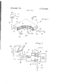
- FIG. 1 is a partially cut away perspective view of a switch incorporating the teachings of this invention.
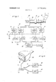
- FIG. 2 is a semi-schematic diagram of a keyboard utilizing switches of this invention.
- FIG. 3 is a semi-schematic diagram of a cable conductor identifying device utilizing switches of this invention.
- FIG. 4 is a semi-schematic diagram of a matrix plate or board utilizing the teachings of this invention shown for use in identifying points on a cathode ray tube.
- the switch for the preferred embodiment of the invention includes a nematic liquid crystal cell 10.
- Cells of this type are well known in the art and are normally employed for display purposes.
- Cell consists of a pair of plates 12 and 14 which are of glass or some other transparent insulating material. Plates 12 and 14 each has a layer of transparent conductive material, 16 and 18 respectively, deposited thereon.
- a layer of nematic liquid crystal material 20 is sandwiched between the plates and the entire unit is sealed by an epoxy or glass fillet 22.
- the plates may either be spaced by the fillet or by means of a polymeric or glass spacer from 6-25 microns thick.
- Transparent conductor 18 is electrically connected through a line 23 to a source of AC potential 24.
- Conductor layer 16 is electrically connected to a wire 26.
- wire 26 may be connected to additional electrical elements or may be terminated in a metal cap 28.
- a simple and inexpensive switch has thus been provided which may be operated in a response to human touch.
- the liquid crystal cell is itself such a high impedance element (in order of 10 meg ohms) that the impedance of the person, and any variations or changes therein, do not affect the operation of the switch.
- the switch still functions satisfactorily even when the person is separated from the floor by a chair and several layers of rubber mats.
- the switch cannot be spuriously excited by dust, dirt or any other particle passing in front of it or by contact with any ungrounded object.
- the device utilizing only small solid state components, may be constructed in a small rugged package and may be operated maintenance free for extremely long periods of time.
- output lines 26 from matrix 42 would depend on the output code being utilized. For example, if the American Standard Code for Information Interchange (ASCII) code is being utilized, seven output lines 26 would be utilized. Each line 26 is connected to one side of a liquid crystal cell 10 with the other side of the cell being connected through a common line 23 to AC source 24. A light emitting diode 32 and photo cell 34 are provided for each cell 10. Output lines 44 from photo cells 34 are connected through a suitable logic and control circuit 46 to an output device.
- ASCII American Standard Code for Information Interchange
- FIG. 3 illustrates another novel application for the switch of this invention.
- a cable 50 which may for example have over 5,000 wires in it, and may be of any desired length, has each of its conductors connected at one end to the terminals of one or more connector elements 52.
- Connector elements 52 are mated to corresponding connector elements 54, the terminals of which are connected through wires 56 to the inputs of an encoding matrix circuit 58.
- Circuit 58 converts the terminal number for each terminal of elements 52 and 54 into a coded representation (for example a binary code) of the terminal on encoder circuit output lines 26.
- a coded representation for example a binary code
- each line 26 is connected to one side of a liquid crystal cell 10 with the other side of the cells being connected through common line 23 to a source of AC potential 24. Any change in the optical characteristics of the cells 10 is detected by photo detector circuits 34 and transmitted through lines 44 to a display encoding circuit 60.
- Encoder 60 converts the binary code for the indicated terminal number of other terminal identifying characters into the code required to operate display device 62.
- Display device 62 may, for example, utilize Nixie tubes, light emitting diodes arrange in suitable matrices, or liquid crystal cells.
- each conductor of cable 50 would initially be connected at one end to a terminal of connector element 52.
- the elements 52 and 54 would then be mated.
- the operator then touches any conductor of the cable 50 at the free end.
- the touching of this conductor causes a circuit to be completed through encoder 58 and the cells 10 corresponding to the binary code for the terminal number of element 52 connected to the other end of the touched conductor.
- the optical state of cells 10 is picked up by detectors 34 and the resulting binary coded number is converted to, for example, a decimal display code in circuit 60.
- Display 62 then generates a decimal indication of the terminal number.
- the operator tags the touched conductor with the determined terminal number in any one of a variety of known ways. It is apparent that, utilizing the device of FIG. 3, the identifying of cable conductors can be easily and quickly accomplished by one relatively unskilled operator.
- FIG. 4 illustrates still another possible application for the switches of this invention.
- a plate 66 of a transparent insulating material is shown mounted to the face of a standard cathode ray tube (CRT) 68.
- CRT cathode ray tube
- Embedded in plate 66 and either flush with the surface thereof or projecting slightly therefrom is a matrix of wires 70.
- the wires 70 would each be relatively thin so as not to interfere with the visability of the display on the CRT.
- the density of wires 70 would depend on the resolution required from the device.
- Wires 70 are bundled into a cable leading from plate 66 into an X-Y encoder circuit 72.
- Encoder 72 generates an output on lines 74 representing, in a suitable code, the X coordinate of a wire 70 which is touched and an output on lines 76 representing, in encoded form, the Y coordinate of the touched wire.
- Lines 74 and 76 are connected to a bank of X liquid crystal switches 78 and a bank of Y liquid crystal switches 80 respectively.
- Each bank of liquid crystal switches generates outputs on lines 44 which may be utilized for any desired purpose.
- the lines 44 could indicate the coordinates of a multiple choice answer selected by the student, causing this answer to be recorded in the system and possibly causing a mark to appear on CRT 68 at the indicated spot to provide the student with feedback as to the answer he selected.
- the operator may touch the desired point on plate 66 with the tip of a sharply pointed conducting stylus.
- a potential problem with the device shown in FIG. 4 is that more than one of the wires 70 may be touched.
- additional circuitry may be included in encoder 72 to average the inputs when two or more simultaneous inputs are received.
- plate 66 While in FIG. 4 plate 66 is shown mounted directly on CRT 68, plate 66 and its associated circuitry may be housed as a stand-alone unit. With this arrangement, a visual indication would be provided on the CRT screen of the position of the finger or stylus on the plate 66. When the indicator shows that the finger or stylus was positioned at the desired point, a key (for example of the type shown in FIG. 2) is operated to cause the coordinates of the point to be stored in a suitable memory.
- the stand-alone unit of the type just described could also be used in numerous other applications where pressure sensitive boards are presently employed. In such applications, the device described herein would be potentially less expensive, smaller in size, less subject to spurious excitation, and have a potentially longer life. It is apparent that, while in FIG. 4 wires 70 have been arranged in plate 66 in a matrix grid, the wires could be arranged in other patterns if desired.
- a touch response switch and numerous applications thereof have thus been provided. While in the discussion so far, a wire 26 is either directly or indirectly touched by a person in order to operate the switch, it is apparent that the switch may be operated in response to the wires 26 being directly or indirectly contacted by an element providing a conductive path to ground or to a potential higher or lower than that of AC source 24 by an amount at least equal to the excitation potential of a liquid crystal cell 10.
- the switch might thus, for example, find application as part of a brushless commutator or in similar applications where detection of a high impedance connection between two conducting elements is required.
- an AC source 24 has been indicated above for the preferred embodiments of the invention, a varying DC potential might also be utilized in some applications.
- An electric switch comprising:
- a high impedance, low voltage electro-optic light valve having terminals on opposite sides thereof, said valve being adapted to have its optical characteristics changed when a potential exceeding a predetermined threshold potential is applied across the valve;
- said member being adapted to be touched in a manner to provide a high impedance path to a potential source which is higher or lower than the potential applied to said one terminal by an amount at least equal to the excitation potential of said valve, a circuit being completed through said valve when said member is touched causing the optical characteristics of said valve to change;
- said member is electrically connected to one of said layers of conductive material.
- a switch of the type described in claim 1 wherein said member is adapted to be touched by a person, said person serving as a high impedance path to ground.
- said suitable means includes coding means selectively connecting said first element to one or more of said valves.
- said detecting means includes a light source and a photo-detector device, said light source and photodetector device being positioned relative to each other so that said photo-detector device is energized by said light source when the optical characteristics of said valve are in one but not the other of the conditions they may be in.
- a device for detecting a person touching an element and for generating an electrical output in response thereto comprising:
- a high impedance, low voltage, electro-optic light valve having terminals on opposite sides thereof, said valve being adapted to have its optical characteristics changed when a potential exceeding a predetermined threshold potential is applied across the valve;
- a device for detecting the touching of one of a plurality of elements and for indicating the element touched comprising;
- each of said valves being adapted to have its optical characteristics changed when a potential exceeding a predetermined threshold potential is applied across the valve;
- each of said elements means for selectively connecting each of said elements to one side of at least one of said light valves, a varying potential being applied to the other side of each of said valves, and a circuit being completed through each valve to which a touched element is connected causing a change to occur in the optical characteristics of each such valve;
- a device of the type described in claim 12 wherein the means for selectively connecting includes coding means for converting a single input from the element touched into a plurality of outputs to said valves.
- said keys being caps of conductive material embedded in an insulating plate
- said coding means includes means for connecting each of said caps to a plurality of outputs to said valves, said outputs representing, in a selected code, the character designated by the key touched.
- said indication generating means includes means for converting the response to said detecting means into a display code of said terminal identifying characters, and means responsive to said converting means for displaying said identifying characters.
- a device of the type described in claim 18 wherein there are a plurality of said conductor tips positioned in a predetermined pattern on the face of said plate;
- said coding means includes means for generating an indication of the coordinates of each of said conductors.
- said detecting means includes a light source and a photo-detector device, said light source and photo-detector device being positioned relative to each other so that said photo-detector device is energized by said light source when the optical characteristics of said valve are in one but not the other of the conditions they may be in.
- An electronic keyboard comprising:
- each of said valves being adapted to have itsoptical characteristics changed when a potential exceeding a predetermined threshold potential is applied across the valve;
- each of said keys means .for connecting each of said keys to one side of a selected one or more of said light valves, the light valves to which each of said keys is connected representing, in a selected code, the character designated by the key;
- a device operative when a conductor of a cable is contacted at one end, for indicating which one of a plurality of terminals the other end of the cable conductor is connected to comprising:
- each of said valves being adapted to have its optical characteristics changed when a potential exceeding a predetermined threshold potential is applied across the valve; means for electrically connecting each of said terminals to one side of at least one of said light valves, an AC potential being applied to the other side of each said valves, and a circuit being completed through each valve to which a terminal is connected when the conductor connected to the terminal is contacted at said one end, causing the optical characteristics of each such valve to change;
- a device for generating an indication of the coordinates of a point which is contacted in a selected manner comprising: i
- a plate of insulating material having a plurality of conductors positioned therein with their tips either flush with or projecting slightly from the upper surface of said plate, said conductor tips being arranged in a predetermined pattern;
- each of said valves being adapted to have its optical characteristics changed when a potential exceeding a predetermined threshold potential is applied across the valve;
- each of said conductors means for connecting each of said conductors to one side of selected ones of at least one group of said light valves, the light valves to which each of said conductors is connected representing in a selected code the coordinates of the position of said conductor in the plate;
- CRT cathode ray tube
- An electric switch comprising:
- a high impedance, low voltage, electro-optic light valve having terminals on opposite sides thereof, said valve being adapted to have its optical characteristics changed when a potential exceeding a predetermined threshold potential is applied across the valve;
Abstract
A high impedance, low voltage, electro-optic light valve, such as, for example, a liquid crystal cell, has one terminal connected to a source of varying potential and the other terminal connected to an element adapted to be touched by a person or otherwise contacted by an impedance path to a potential which is highe or lower than the varying potential by an amount at least equal to the excitation potential of the valve. When the element is contacted, a circuit is completed through the valve, causing its optical characteristics to change. A touch (contact) responsive switch is provided by detecting the change in the optical characteristics of the valve and by generating some sort of output in response thereto. The switch may be utilized in devices such as a keyboard, a cable conductor identifier, or a touch response matrix board where an indication is required as to which of a plurality of elements has been touched or otherwise contacted. For such applications, the elements to be touched are connected through a suitable coding means to a bank of valves. The outputs from the valve detectors indicate, in a suitable code, the element touched. This invention relates to a low current electric switch which may be actuated in response to a person touching an element and to various devices, including an electronic keyboard, a cable conductor identifier, and a touch responsive matrix board, utilizing the switch.
Description
United Statr Masi [ TOUCH RESPONSIVE ELECTRIC SWITCH AND DEVICE FOR THE USE THEREOF [75] Inventor: James Vincent Masi, Monroe,
Conn.
[73] Assignee: BunkerRamo Corporation, Oak
Brook, Ill.
22 Filed: Mar. 29, 1972 21 Appl. No.: 239,117
[56] References Cited UNITED STATES PATENTS 5/1972 Garfein et al. 340/324 R 4/1964 Lieb 9/1965 Bray 340/365 C Primary Examiner-John W. Caldwell Assistant Examiner-Marshall M. Curtis Attorney-Frederick M. Arbuckle P140 PHO T0 T 06 75c TOR DE rc roR L/UU/O gu p CRYSTHL CRYSI'HL CELL CELL 1451 Nov. 13,1973
[57] ABSTRACT A high impedance, low voltage, electro-optic light valve, such as, for example, a liquid crystal cell, has one terminal connected to a source of varying potential and the other terminal connected to an element adapted to be touched by a person or otherwise contacted by an impedance path to a potential which is highe or lower than the varying potential by an amount at least equal to the excitation potential of the valve. When the element is contacted, a circuit is completed through the valve, causing its optical characteristics to change. A touch (contact) responsive switch is provided by detecting the change in the optical characteristics of the valve and by generating some sort of output in response thereto.
The switch may be utilized in devices such as a keyboard, a cable conductor identifier, or a touch response matrix board where an indication is required as to which of a plurality of elements has been touched or otherwise contacted. For such applications, the elements to be touched are connected through a suitable coding means to a bank of valves. The outputs from the valve detectors indicate, in a suitable code, the element touched.
30 Claims, 4 Drawing Figures PHOTO PHOTO DE ECTOR DETECTOR 44 D/SPLHY sumo/Ne; DISPZHY 6'0 C/RCU/ T new; saozeeec TOUCH RESPONSIVE ELECTRIC SWITCH AND DEVICE FOR THE USE THEREOF This invention relates to a low current electric switch which may be actuated in response to a person touching an element and to various devices, including an electronic keyboard, a cable conductor identifier, and a touch responsive matrix board, utilizing the switch.
BACKGROUND It has been known for many years that when a person touches a wire or similar electrically conductive element, the person may serve as a high impedance path to ground. However, the high impedance of the person results in extremely small currents flowing through circuits of which he is a part. Since suitable switching devices for detecting and utilizing such small currents are not readily available, there has heretofore been little exploitation of the human conduction phenomenon.
In recent years, however, high impedance, low voltage, electro-optic light valves, such as nematic liquid crystal cells, have become available. While these cells have heretofore been utilized primarily for display purposes, it will be apparent in the discussion to follow that valves or cells of this type may also be utilized in high impedance switches, permitting more extensive use of the human conductivity phenomenon. I
Switches of this type, being high impedance devices, require a minimum of power to operate and have inherently high noise resistance. Further, they may be fabricated completely from solid state devices, without moving parts to wear out, and are thus easy to package, of small size with a thin profile, adaptable for a wide variety of configurations, rugged, relatively maintenance free, and of extremely long life. They are thus inexpensive both to manufacture and maintain.
For the reasons indicated above, the switch of this invention may be advantageously utilized for applications in which a mechanical switch is now employed. In applications such as, for example, an elevator switch, the switch of this invention would have a potentially longer life but would not have the disadvantage of being spuriously excited by dust or other particles as is the case with existing electronic photo-detector switches. In the discussion to follow, an electronic keyboard utilizing the switches of this invention will also be presented.
In addition, the switch of this invention may be utilized as part of devices for performing functions not heretofore available. With large cables, some of which may have several thousand conductors, a problem exists when connecting the cable in identifying the conductor at one end which corresponds to a conductor at the other end. Heretofore, a tedious, time consuming, and extremely expensive ringing operation, normally requiring two men, has been required to match the conductors. Color coding of the wire reduces the problem, but by no means eliminates it. Recently, a device has come on the market which permits one end of the cable to be attached to terminals and a numeric indication to be generated of the terminal to which the one end of the conductor is connected when the other end of the conductor is touched with a suitable tool. This device, while a vast improvement over the prior art, still requires that the operator use two hands in the operation, and is relatively complicated and expensive. The switch of this invention permits the function to be performed with only one hand, the finger of the hand touching the conductor directly, and by use of relatively simple and inexpensive hardware.
A problem also exists in providing a user with the capability of marking on a cathode ray tube (CRT) or similar display a point which is to be identified, or at which a function is to be performed. Heretofore, light pens have been utilized to perform this function. However, to use a light pen, a special, relatively expensive CRT is required in addition to the requirement for the light pen itself. Further, the light pen usually covers a relatively large area and is thus not adapted for providing extremely high resolution. Finally, this form of input is sometimes utilized by children in teaching machine applications. The relatively hard surface of the light pen could scratch or crack the face of the CRT if it is improperly operated by a young person. It would therefore be preferable if the operator could merely touch the desired spot on the screen with a soft finger or, in applications where high resolution is required, with the sharp tip of a conducting stylus.
In the discussion to follow, a device will be described which can either be fitted to the face of a standard CRT to permit the above functions to be performed or can be used like a keyboard in conjunction with a cursor on the face of the screen to indicate a desired point. In the latter mode of operation, the device functions in place of a pressure responsive tactile board and may be employed in most applications where such boards are presently utilized. It should, however, be smaller, lighter, less subject to noise, longer lasting, require less maintenance, and require less power than a tactile board. Further, it can provide direct X-Y output readings without requiring the scanning of output lines.
SUMMARY OF THE INVENTION Briefly, this invention provides an electronic switch consisting of a high impedance, low voltage, electrooptic light valve having terminals on opposite sides. A means is provided for applying a potential to one terminal of the valve, preferably an AC potential, while the other terminal is physically and electrically connected by a suitable means to an element adapted to be touched either directly or indirectly by a person. The switch could also be operated if the element is contacted by some other member which is connected through a high impedance to a potential higher or lower than that of the AC supply by an amount at least equal to the excitation potential of the valve. When the element is touched or contacted, a circuit is completed through the valve, causing the optical characteristics of the valve to be changed. The final element of the switch is a means for detecting the change in the optical characteristics of the valve and of generating some sort of an output in response thereto.
For preferred embodiments of the invention, the light valve is a liquid crystal cell. A number of these cells may be utilized as part of a device for detecting the touching of one of a plurality of elements and for indicating the element touched. For these devices, a means is provided for selectively connecting each of the elements to one side of at least one of the light valves with the AC potential being applied to the other side of each of the valves. A detecting means is provided for each of the valves and a means is provided which is responsive to the detecting means for generating an indication of the element touched. The element touched may be the key of a keyboard, the end of a cable conductor where the other end of the conductor is connected through suitable means to the device, a conductor in a matrix of conductors attached to the face of a CRT, a touch responsive matrix board, or the like.
The foregoing and other objects, features and advantages of the invention will be apparent from the following more particular description of preferred embodiments of the invention as illustrated in the accompanying drawings.
BRIEF DESCRIPTION OF DRAWINGS FIG. 1 is a partially cut away perspective view of a switch incorporating the teachings of this invention.
FIG. 2 is a semi-schematic diagram of a keyboard utilizing switches of this invention.
FIG. 3 is a semi-schematic diagram of a cable conductor identifying device utilizing switches of this invention.
FIG. 4 is a semi-schematic diagram of a matrix plate or board utilizing the teachings of this invention shown for use in identifying points on a cathode ray tube.
DETAILED DESCRIPTION OF SWITCH From FIG. 1, it is seen that the switch for the preferred embodiment of the invention includes a nematic liquid crystal cell 10. Cells of this type are well known in the art and are normally employed for display purposes. Cell consists of a pair of plates 12 and 14 which are of glass or some other transparent insulating material. Plates 12 and 14 each has a layer of transparent conductive material, 16 and 18 respectively, deposited thereon. A layer of nematic liquid crystal material 20 is sandwiched between the plates and the entire unit is sealed by an epoxy or glass fillet 22. The plates may either be spaced by the fillet or by means of a polymeric or glass spacer from 6-25 microns thick. Transparent conductor 18 is electrically connected through a line 23 to a source of AC potential 24. Conductor layer 16 is electrically connected to a wire 26. Depending on the application, wire 26 may be connected to additional electrical elements or may be terminated in a metal cap 28.
In operation, when a persons finger 30 touches cap 28, the cap is capacitively coupled through the person to ground. The potential of conductive layer 16 is thus reduced to ground. Assuming that the potential of AC source 24 is greater than the excitation potential of cell 10, the liquid crystal material becomes turbulent with its molecules having dipole moments at various angles. This results in a dynamic scattering of light applied to the crystal giving the normally transparent material an opaque appearance. The change in the optical characteristics of the liquid crystal cell is detected by use of light source 32 and photo detector 34. As illustrated, photo cell 34 normally generates an output and has the output interrupted when the switch is operated. If an output is desired when the switch is operated, light source 32A (shown dotted) may be substituted for light source 32. The light from source 32A would normally pass through cell 10. However, when the cell is excited, the light is reflected by the opaque liquid crystal layer and is picked up by photo detector 34 generating the desired output. Light source 32 may be a light emitting diode to provide an all solid state switch unit.
A simple and inexpensive switch has thus been provided which may be operated in a response to human touch. The liquid crystal cell is itself such a high impedance element (in order of 10 meg ohms) that the impedance of the person, and any variations or changes therein, do not affect the operation of the switch. Experiments have indicated that the switch still functions satisfactorily even when the person is separated from the floor by a chair and several layers of rubber mats. However, in spite of its sensitivity, the switch cannot be spuriously excited by dust, dirt or any other particle passing in front of it or by contact with any ungrounded object. Further, the device, utilizing only small solid state components, may be constructed in a small rugged package and may be operated maintenance free for extremely long periods of time.
DESCRIPTION OF APPLICATIONS As indicated previously, the small size, low cost, high reliability, long life and lack of required maintenance for the switch of this invention would make it useful in many applications, such as elevator switches, where mechanical switches are now employed. Another advantage of these switches is that, because of the previously indicated high impedance of cell 10, additional elements may be inserted between the contact point (for example cap 28) and a cell 10 without adversely affecting the performance of the device. Thus, referring to FIG. 2 in which an electronic keyboard utilizing the switches of this invention is shown, it is seen that the keys 28 are metal caps or metal clad caps secured. in a suitable plate 38 of insulating material. Each cap 28 is connected through a wire 40 to a diode or other equivalent encoding matrix 42. The number of output lines 26 from matrix 42 would depend on the output code being utilized. For example, if the American Standard Code for Information Interchange (ASCII) code is being utilized, seven output lines 26 would be utilized. Each line 26 is connected to one side of a liquid crystal cell 10 with the other side of the cell being connected through a common line 23 to AC source 24. A light emitting diode 32 and photo cell 34 are provided for each cell 10. Output lines 44 from photo cells 34 are connected through a suitable logic and control circuit 46 to an output device.
In operation, each time a key 28 is touched, a circuit is completed through the appropriate line 40 and the diode matrix to a selected combination of the lines 26. This causes corresponding ones of the cells 10 to be operated resulting in outputs on the corresponding lines 44.
While the lack of feel with the keyboard of FIG. 2 and a possible speed problem resulting from the recovery time of the cells 10 may limit the usefullness of this device in applications such as typewriters, the small size and lack of maintenance of the switches might make them ideal for applications such as in small calculating machines.
FIG. 3 illustrates another novel application for the switch of this invention. In this FIG. a cable 50 which may for example have over 5,000 wires in it, and may be of any desired length, has each of its conductors connected at one end to the terminals of one or more connector elements 52. Connector elements 52 are mated to corresponding connector elements 54, the terminals of which are connected through wires 56 to the inputs of an encoding matrix circuit 58. Circuit 58 converts the terminal number for each terminal of elements 52 and 54 into a coded representation (for example a binary code) of the terminal on encoder circuit output lines 26. Thus, a cable having 1,000 conductors would require output lines 26 (assuming the use of binary code), while for a cable having 4,000 conductors, 12 lines 26 would be required. As with other applications, each line 26 is connected to one side of a liquid crystal cell 10 with the other side of the cells being connected through common line 23 to a source of AC potential 24. Any change in the optical characteristics of the cells 10 is detected by photo detector circuits 34 and transmitted through lines 44 to a display encoding circuit 60. Encoder 60 converts the binary code for the indicated terminal number of other terminal identifying characters into the code required to operate display device 62. Display device 62 may, for example, utilize Nixie tubes, light emitting diodes arrange in suitable matrices, or liquid crystal cells.
In operation, each conductor of cable 50 would initially be connected at one end to a terminal of connector element 52. The elements 52 and 54 would then be mated. The operator then touches any conductor of the cable 50 at the free end. The touching of this conductor causes a circuit to be completed through encoder 58 and the cells 10 corresponding to the binary code for the terminal number of element 52 connected to the other end of the touched conductor. The optical state of cells 10 is picked up by detectors 34 and the resulting binary coded number is converted to, for example, a decimal display code in circuit 60. Display 62 then generates a decimal indication of the terminal number. The operator then tags the touched conductor with the determined terminal number in any one of a variety of known ways. It is apparent that, utilizing the device of FIG. 3, the identifying of cable conductors can be easily and quickly accomplished by one relatively unskilled operator.
FIG. 4 illustrates still another possible application for the switches of this invention. In this FIG. a plate 66 of a transparent insulating material is shown mounted to the face of a standard cathode ray tube (CRT) 68. Embedded in plate 66 and either flush with the surface thereof or projecting slightly therefrom is a matrix of wires 70. The wires 70 would each be relatively thin so as not to interfere with the visability of the display on the CRT. The density of wires 70 would depend on the resolution required from the device. Wires 70 are bundled into a cable leading from plate 66 into an X-Y encoder circuit 72. Encoder 72 generates an output on lines 74 representing, in a suitable code, the X coordinate of a wire 70 which is touched and an output on lines 76 representing, in encoded form, the Y coordinate of the touched wire. Lines 74 and 76 are connected to a bank of X liquid crystal switches 78 and a bank of Y liquid crystal switches 80 respectively. Each bank of liquid crystal switches generates outputs on lines 44 which may be utilized for any desired purpose. For example, in a teaching machine application, the lines 44 could indicate the coordinates of a multiple choice answer selected by the student, causing this answer to be recorded in the system and possibly causing a mark to appear on CRT 68 at the indicated spot to provide the student with feedback as to the answer he selected. In applications where resolution finer than that obtainable with a finger is required, the operator may touch the desired point on plate 66 with the tip of a sharply pointed conducting stylus.
A potential problem with the device shown in FIG. 4 is that more than one of the wires 70 may be touched.
If the resolution of the wires is fine enough that this appears to be a potential problem, additional circuitry may be included in encoder 72 to average the inputs when two or more simultaneous inputs are received.
While in FIG. 4 plate 66 is shown mounted directly on CRT 68, plate 66 and its associated circuitry may be housed as a stand-alone unit. With this arrangement, a visual indication would be provided on the CRT screen of the position of the finger or stylus on the plate 66. When the indicator shows that the finger or stylus was positioned at the desired point, a key (for example of the type shown in FIG. 2) is operated to cause the coordinates of the point to be stored in a suitable memory. The stand-alone unit of the type just described could also be used in numerous other applications where pressure sensitive boards are presently employed. In such applications, the device described herein would be potentially less expensive, smaller in size, less subject to spurious excitation, and have a potentially longer life. It is apparent that, while in FIG. 4 wires 70 have been arranged in plate 66 in a matrix grid, the wires could be arranged in other patterns if desired.
A touch response switch and numerous applications thereof have thus been provided. While in the discussion so far, a wire 26 is either directly or indirectly touched by a person in order to operate the switch, it is apparent that the switch may be operated in response to the wires 26 being directly or indirectly contacted by an element providing a conductive path to ground or to a potential higher or lower than that of AC source 24 by an amount at least equal to the excitation potential of a liquid crystal cell 10. The switch might thus, for example, find application as part of a brushless commutator or in similar applications where detection of a high impedance connection between two conducting elements is required. Further, while an AC source 24 has been indicated above for the preferred embodiments of the invention, a varying DC potential might also be utilized in some applications. A fixed DC potential may be used where the switch is not applied as a touch responsive element and there is pure resistive coupling between the contacted element and ground. Thus, while the invention has been particularly shown and described above with reference to preferred embodiments thereof, it will be apparent to those skilled in the art that the foregoing and other changes in form and detail may be made therein without departing from the spirit and scope of the invention.
What is claimed is:
1. An electric switch comprising:
a high impedance, low voltage electro-optic light valve having terminals on opposite sides thereof, said valve being adapted to have its optical characteristics changed when a potential exceeding a predetermined threshold potential is applied across the valve;
means for applying a potential to one terminal of said valve;
an electrically conductive member which is normally open circuited;
means for electrically connecting the other terminal of said valve to said member;
said member being adapted to be touched in a manner to provide a high impedance path to a potential source which is higher or lower than the potential applied to said one terminal by an amount at least equal to the excitation potential of said valve, a circuit being completed through said valve when said member is touched causing the optical characteristics of said valve to change; and
means for detecting the change in the optical charcteristics of said valve, and for generating an electrical output in response thereto.
2. A switch of the type described in claim 1 wherein said light valve is a liquid crystal cell.
3. A switch of the type described in claim 2 wherein said cell includes a layer of liquid crystal material sandwiched between layers of conductive material; and
wherein said member is electrically connected to one of said layers of conductive material.
4. A switch of described type described in claim 1 wherein potential applied to said one terminal is varied in accordance with some pattern.
5. A switch of the type described in claim 4 wherein the potential applied to said one terminal is an AC potential.
6. A switch of the type described in claim 1 wherein said member is adapted to be touched by a person, said person serving as a high impedance path to ground.
7. A switch of the type described in claim 6 wherein said member is a metal cap connected through suitable means to said one terminal of the valve.
8. A switch of the type described in claim 7 wherein there are more than one of said valves; and
wherein said suitable means includes coding means selectively connecting said first element to one or more of said valves.
9. A switch of the type described in claim 1 wherein said detecting means includes a light source and a photo-detector device, said light source and photodetector device being positioned relative to each other so that said photo-detector device is energized by said light source when the optical characteristics of said valve are in one but not the other of the conditions they may be in.
10. A switch of the type described in claim 9 wherein said light source is a light emitting diode.
11. A device for detecting a person touching an element and for generating an electrical output in response thereto comprising:
a high impedance, low voltage, electro-optic light valve having terminals on opposite sides thereof, said valve being adapted to have its optical characteristics changed when a potential exceeding a predetermined threshold potential is applied across the valve;
means for applying a varying potential to one terminal of said valve;
means for physically and electrically connecting the other terminal of the valve to said element, a circuit being completed through said valve when said element is touched, causing the optical characteristics of said valve to change; and
means for detecting the change in the optical characteristics of said valve and for generating said electrical output in response thereto.
12. A device for detecting the touching of one of a plurality of elements and for indicating the element touched comprising;
a plurality of high impedance, low voltage, electrooptic light valves, each of said valves being adapted to have its optical characteristics changed when a potential exceeding a predetermined threshold potential is applied across the valve;
means for selectively connecting each of said elements to one side of at least one of said light valves, a varying potential being applied to the other side of each of said valves, and a circuit being completed through each valve to which a touched element is connected causing a change to occur in the optical characteristics of each such valve;
means for detecting the change in the optical characteristics of the valves; and
means responsive to said detecting means for generating an indication of the element touched.
13. A device of the type described in claim 12 wherein the means for selectively connecting includes coding means for converting a single input from the element touched into a plurality of outputs to said valves.
14. A device of the type described in claim 13 wherein said device is an electronic keyboard;
wherein said elements are the keys of said keyboard,
said keys being caps of conductive material embedded in an insulating plate;
and wherein said coding means includes means for connecting each of said caps to a plurality of outputs to said valves, said outputs representing, in a selected code, the character designated by the key touched.
15. A device of the type described in claim 13 wherein said element is a conductor of a cable, the end of the conductor opposite the end being touched being connected to a terminal which may be characterized by certain identifying characters;
and wherein the outputs from said coding means represent in a selected code the identifying characters of said terminal.
16. A device of the type described in claim 15 wherein said identifying characters are numbers and said selected code is a binary code.
17. A device of the type described in claim 15 wherein said indication generating means includes means for converting the response to said detecting means into a display code of said terminal identifying characters, and means responsive to said converting means for displaying said identifying characters.
18. A device of the type described in claim 13 wherein said element is the tip of a conductor which is either flush with or projecting slightly from the face of a plate of insulating material.
19. A device of the type described in claim 18 wherein there are a plurality of said conductor tips positioned in a predetermined pattern on the face of said plate;
and wherein said coding means includes means for generating an indication of the coordinates of each of said conductors.
20. A device of the type described in claim 19 wherein said plate is of a transparent material and is adapted to be positioned in front of the face of a cathode ray tube.
21. A device of the type described in claim 12 wherein said light valves are liquid crystal cells.
22. A device of the type described in claim 12 wherein said detecting means includes a light source and a photo-detector device, said light source and photo-detector device being positioned relative to each other so that said photo-detector device is energized by said light source when the optical characteristics of said valve are in one but not the other of the conditions they may be in.
23. A device of the type described in claim 22 wherein there is a light source and a photo-detector device for each of said valves.
24. An electronic keyboard comprising:
a plurality of character designating keys, each formed of a conductive material;
a plurality of high impedance, low voltage, electrooptic light valves, each of said valves being adapted to have itsoptical characteristics changed when a potential exceeding a predetermined threshold potential is applied across the valve;
means .for connecting each of said keys to one side of a selected one or more of said light valves, the light valves to which each of said keys is connected representing, in a selected code, the character designated by the key;
means for applying a varying potential to the other side of each of said light valves;
whereby when a key is touched, a high impedance path to ground is provided, completing a circuit through each valve to which the touched key is connected, causing the optical characteristics of each said valve to change;
means for detecting the change in optical characteristics of each of said valves; and
means responsive to said detecting means for generating coded outputs representing the designated character for each touched key. 25. A device operative when a conductor of a cable is contacted at one end, for indicating which one of a plurality of terminals the other end of the cable conductor is connected to comprising:
a plurality of high impedance, low voltage, electrooptic light valves, each of said valves being adapted to have its optical characteristics changed when a potential exceeding a predetermined threshold potential is applied across the valve; means for electrically connecting each of said terminals to one side of at least one of said light valves, an AC potential being applied to the other side of each said valves, and a circuit being completed through each valve to which a terminal is connected when the conductor connected to the terminal is contacted at said one end, causing the optical characteristics of each such valve to change;
means for detecting the change in optical characteristics of the valves; and
means responsive to said detecting means for indicating the terminal connected to the conductor which is contacted at said one end.
26. A device for generating an indication of the coordinates of a point which is contacted in a selected manner comprising: i
a plate of insulating material having a plurality of conductors positioned therein with their tips either flush with or projecting slightly from the upper surface of said plate, said conductor tips being arranged in a predetermined pattern;
a plurality of high impedance, low voltage, electrooptic light valves, each of said valves being adapted to have its optical characteristics changed when a potential exceeding a predetermined threshold potential is applied across the valve;
means for connecting each of said conductors to one side of selected ones of at least one group of said light valves, the light valves to which each of said conductors is connected representing in a selected code the coordinates of the position of said conductor in the plate;
means for applying a varying potential to the other side of each of said light valves;
whereby when a conductor is contacted, a circuit is completed through each valve to which the contacted conductor is connected, causing the optical characters of each said valve to change;
means for detecting the change in optical characters of each of said valves; and
means responsive to said detecting means for generating outputs in a selected code representing the coordinates of the contacted conductor.
27. A device of the type described in claim 26 wherein said point is contacted by being touched by a person.
28. A device of the type described in claim 26 wherein said predetermined pattern is a matrix grid.
29. A device of the type described in claim 27 wherein said insulating plate is of a transparent material and is adapted to be positioned in front of a cathode ray tube (CRT) to permit points on the CRT screen to be identified and an indication of the coordinates of the identified points to be generated.
30. An electric switch comprising:
A high impedance, low voltage, electro-optic light valve having terminals on opposite sides thereof, said valve being adapted to have its optical characteristics changed when a potential exceeding a predetermined threshold potential is applied across the valve;
an electrically conductive member adapted to be touched in a predetermined manner;
means for series connecting said member and valve;
means, including said series connecting means, normally operative for open circuiting said valve, said means being operative when said member is touched for completing a circuit through said valve with the potential thereacross exceeding said excitation potential, whereby the optical characteristics of said valve are changed; and
means for detecting the change in the optical characteristics of said valve, and for generating an electrical output in response thereto. =0
Claims (30)
1. An electric switch comprising: a high impedance, low voltage electro-optic light valve having terminals on opposite sides thereof, said valve being adapted to have its optical characteristics changed when a potential exceeding a predetermined threshold potential is applied across the valve; means for applying a potential to one terminal of said valve; an electrically conductive member which is normally open circuited; means for electrically connecting the other terminal of said valve to said member; said member being adapted to be touched in a manner to provide a high impedance path to a potential source which is higher or lower than the potential applied to said one terminal by an amount at least equal to the excitation potential of said valve, a circuit being completed through said valve when said member is touched causing the optical characteristics of said valve to change; and means for detecting the change in the optical charcteristics of said valve, and for generating an electrical output in response thereto.
2. A switch of the type described in claim 1 wherein said light valve is a liquid crystal cell.
3. A switch of the type described in claim 2 wherein said cell includes a layer of liquid crystal material sandwiched between layers of conductive material; and wherein said member is electrically connected to one of said layers of conductive material.
4. A switch of described type dexcribed in claim 1 wherein potential applied to said one terminal is varied in accordance with some pattern.
5. A switch of the type described in claim 4 wherein the potential applied to said one terminal is an AC potential.
6. A switch of the type described in claim 1 wherein said member is adapted to be touched by a person, said person serving as a high impedance path to ground.
7. A switch of the type described in claim 6 wherein said member is a metal cap connected through suitable means to said one terminal of the valve.
8. A switch of the type described in claim 7 wherein there are more than one of said valves; and wherein said suitable means includes coding means selectively connecting said first element to one or more of said valves.
9. A switch of the type described in claim 1 wherein said detecting means includes a light source and a photo-detector device, said light source and photo-detector device being positioned relative to each other so that said photo-detector device is energized by said light source when the optical characteristics of said valve are in one but not the other of the conditions they may be in.
10. A switch of the type described in claim 9 wherein said light source is a light emitting diode.
11. A device for detecting a person touching an element and for generating an electrical output in response thereto comprising: a high impedance, low voltage, electro-optic light valve having terminals on opposite sides thereof, said valve being adapted to have its optical characteristics changed when a potential exceeding a predetermined threshold potential is applied across the valve; means for applying a varying potential to one terminal of said valve; means for physically and electrically connecting the other terminal of the valve to said element, a circuit being completed through said valve when said element is touched, causing the optical characteristics of said valve to change; and means for detecting the change in the optical characteristics of said valve and for generating said electrical output in response thereto.
12. A device for detecting the touching of one of a plurality of elements and for indicating the element touched comprising; a plurality of high impedance, low voltage, electro-optic light valves, each of said valves being adapted to have its optical characteristics changed when a potential exceeding a predetermined threshold potential is applied across the valve; means for selectively connecting each of said elements to one side of at least one of said light valves, a varying potential being applied to the other side of each of said valves, and a circuit being completed through each valve to which a touched element is connected causing a change to occur in the optical characteristics of each such valve; means for detecting the change in the optical characteristics of the valves; and means responsive to said detecting means for generating an indication of the element touched.
13. A device of the type described in claim 12 wherein the means for selectively connecting includes coding means for converting a single input from the element touched into a plurality of outputs to said valves.
14. A device of the type described in claim 13 wherein said device is an electronic keyboard; wherein said elements are the keys of said keyboard, said keys being caps of conductive material embedded in an insulating plate; and wherein said coding means includes means for connecting each of said caps to a plurality of outputs to said valves, said outputs representing, in a selected code, the character designated by the key touched.
15. A device of the type described in claim 13 wherein said element is a conductor of a cable, the end of the conductor opposite the end being touched being connected to a terminal which may be characterized by certain identifying characters; and wherein the outputs from said coding means represent in a selected code the identifying characters of said terminal.
16. A device of the type described in claim 15 wherein said identifying characters are numbers and said selected code is a binary code.
17. A device of the type described in claim 15 wherein said indication generating means includes means for converting the response to said detecting means into a display code of said terminal identifying characters, and means responsive to said converting means for displaying said identifying characters.
18. A device of the type described in claim 13 wherein said element is the tip of a conductor which is either flush with or projecting slightly from the face of a plate of insulating material.
19. A device of the type described in claim 18 wherein there are a plurality of said conductor tips positioned in a predetermined pattern on thE face of said plate; and wherein said coding means includes means for generating an indication of the coordinates of each of said conductors.
20. A device of the type described in claim 19 wherein said plate is of a transparent material and is adapted to be positioned in front of the face of a cathode ray tube.
21. A device of the type described in claim 12 wherein said light valves are liquid crystal cells.
22. A device of the type described in claim 12 wherein said detecting means includes a light source and a photo-detector device, said light source and photo-detector device being positioned relative to each other so that said photo-detector device is energized by said light source when the optical characteristics of said valve are in one but not the other of the conditions they may be in.
23. A device of the type described in claim 22 wherein there is a light source and a photo-detector device for each of said valves.
24. An electronic keyboard comprising: a plurality of character designating keys, each formed of a conductive material; a plurality of high impedance, low voltage, electro-optic light valves, each of said valves being adapted to have its optical characteristics changed when a potential exceeding a predetermined threshold potential is applied across the valve; means for connecting each of said keys to one side of a selected one or more of said light valves, the light valves to which each of said keys is connected representing, in a selected code, the character designated by the key; means for applying a varying potential to the other side of each of said light valves; whereby when a key is touched, a high impedance path to ground is provided, completing a circuit through each valve to which the touched key is connected, causing the optical characteristics of each said valve to change; means for detecting the change in optical characteristics of each of said valves; and means responsive to said detecting means for generating coded outputs representing the designated character for each touched key.
25. A device operative when a conductor of a cable is contacted at one end, for indicating which one of a plurality of terminals the other end of the cable conductor is connected to comprising: a plurality of high impedance, low voltage, electro-optic light valves, each of said valves being adapted to have its optical characteristics changed when a potential exceeding a predetermined threshold potential is applied across the valve; means for electrically connecting each of said terminals to one side of at least one of said light valves, an AC potential being applied to the other side of each said valves, and a circuit being completed through each valve to which a terminal is connected when the conductor connected to the terminal is contacted at said one end, causing the optical characteristics of each such valve to change; means for detecting the change in optical characteristics of the valves; and means responsive to said detecting means for indicating the terminal connected to the conductor which is contacted at said one end.
26. A device for generating an indication of the coordinates of a point which is contacted in a selected manner comprising: a plate of insulating material having a plurality of conductors positioned therein with their tips either flush with or projecting slightly from the upper surface of said plate, said conductor tips being arranged in a predetermined pattern; a plurality of high impedance, low voltage, electro-optic light valves, each of said valves being adapted to have its optical characteristics changed when a potential exceeding a predetermined threshold potential is applied across the valve; means for connecting each of said conductors to one side of selected ones of at least one group of said light valves, the light valves to which each of said conductors is connected representing in a selected code the coordinates of the position of said condUctor in the plate; means for applying a varying potential to the other side of each of said light valves; whereby when a conductor is contacted, a circuit is completed through each valve to which the contacted conductor is connected, causing the optical characters of each said valve to change; means for detecting the change in optical characters of each of said valves; and means responsive to said detecting means for generating outputs in a selected code representing the coordinates of the contacted conductor.
27. A device of the type described in claim 26 wherein said point is contacted by being touched by a person.
28. A device of the type described in claim 26 wherein said predetermined pattern is a matrix grid.
29. A device of the type described in claim 27 wherein said insulating plate is of a transparent material and is adapted to be positioned in front of a cathode ray tube (CRT) to permit points on the CRT screen to be identified and an indication of the coordinates of the identified points to be generated.
30. An electric switch comprising: A high impedance, low voltage, electro-optic light valve having terminals on opposite sides thereof, said valve being adapted to have its optical characteristics changed when a potential exceeding a predetermined threshold potential is applied across the valve; an electrically conductive member adapted to be touched in a predetermined manner; means for series connecting said member and valve; means, including said series connecting means, normally operative for open circuiting said valve, said means being operative when said member is touched for completing a circuit through said valve with the potential thereacross exceeding said excitation potential, whereby the optical characteristics of said valve are changed; and means for detecting the change in the optical characteristics of said valve, and for generating an electrical output in response thereto.
Applications Claiming Priority (1)
| Application Number | Priority Date | Filing Date | Title |
|---|---|---|---|
| US23911772A | 1972-03-29 | 1972-03-29 |
Publications (1)
| Publication Number | Publication Date |
|---|---|
| US3772685A true US3772685A (en) | 1973-11-13 |
Family
ID=22900686
Family Applications (1)
| Application Number | Title | Priority Date | Filing Date |
|---|---|---|---|
| US00239117A Expired - Lifetime US3772685A (en) | 1972-03-29 | 1972-03-29 | Touch responsive electric switch and device for the use thereof |
Country Status (1)
| Country | Link |
|---|---|
| US (1) | US3772685A (en) |
Cited By (25)
| Publication number | Priority date | Publication date | Assignee | Title |
|---|---|---|---|---|
| US3846791A (en) * | 1972-10-02 | 1974-11-05 | R Foster | Solid state keyboard |
| US3879722A (en) * | 1973-12-10 | 1975-04-22 | Bell Telephone Labor Inc | Interactive input-output computer terminal with automatic relabeling of keyboard |
| US3902026A (en) * | 1974-01-18 | 1975-08-26 | Electronic Control Systems Inc | Method and apparatus for identifying wires |
| US3909113A (en) * | 1974-05-01 | 1975-09-30 | Us Navy | Optical coupler |
| US3974472A (en) * | 1974-04-04 | 1976-08-10 | General Motors Corporation | Domestic appliance control and display panel |
| US4017848A (en) * | 1975-05-19 | 1977-04-12 | Rockwell International Corporation | Transparent keyboard switch and array |
| US4024536A (en) * | 1974-09-20 | 1977-05-17 | Leif Georg Lennart Andersson | Method and a device for character presentation |
| US4078257A (en) * | 1976-08-23 | 1978-03-07 | Hewlett-Packard Company | Calculator apparatus with electronically alterable key symbols |
| US4092640A (en) * | 1975-09-27 | 1978-05-30 | Sharp Kabushiki Kaisha | Key input means having a switching element made of a light emitting diode |
| US4202607A (en) * | 1975-03-17 | 1980-05-13 | Sharp Kabushiki Kaisha | Mirror with information display |
| US4224615A (en) * | 1978-09-14 | 1980-09-23 | Texas Instruments Incorporated | Method of using a liquid crystal display device as a data input device |
| US4305007A (en) * | 1979-08-22 | 1981-12-08 | Gerald N. Stan | Electronic two directional control apparatus |
| USRE32040E (en) * | 1976-08-23 | 1985-11-26 | Calculator apparatus with electronically alterable key symbols | |
| US4581577A (en) * | 1982-12-15 | 1986-04-08 | Her Majesty The Queen In Right Of Canada, As Represented By The Minister Of National Defence Of Her Majesty's Canadian Government | Continuity detecting apparatus |
| US4611280A (en) * | 1984-03-12 | 1986-09-09 | At&T Bell Laboratories | Sorting method |
| US4761526A (en) * | 1986-05-12 | 1988-08-02 | Terumo Kabushiki Kaisha | Apparatus for reading displayed value of electronic clinical thermometer |
| US4839634A (en) * | 1986-12-01 | 1989-06-13 | More Edward S | Electro-optic slate for input/output of hand-entered textual and graphic information |
| US4893115A (en) * | 1985-11-12 | 1990-01-09 | John Fluke Mfg. Co., Inc. | Touch sensitive visual display system |
| US5194852A (en) * | 1986-12-01 | 1993-03-16 | More Edward S | Electro-optic slate for direct entry and display and/or storage of hand-entered textual and graphic information |
| US5398041A (en) * | 1970-12-28 | 1995-03-14 | Hyatt; Gilbert P. | Colored liquid crystal display having cooling |
| US5432526A (en) * | 1970-12-28 | 1995-07-11 | Hyatt; Gilbert P. | Liquid crystal display having conductive cooling |
| US6133906A (en) * | 1993-03-15 | 2000-10-17 | Microtouch Systems, Inc. | Display-integrated stylus detection system |
| US6765193B2 (en) * | 2001-08-21 | 2004-07-20 | National Science And Technology Development Agency | Optical touch switch structures |
| US9417754B2 (en) | 2011-08-05 | 2016-08-16 | P4tents1, LLC | User interface system, method, and computer program product |
| DE102018202668B4 (en) * | 2018-02-22 | 2021-03-04 | Audi Ag | Operating device and method for controlling at least one functional unit for a motor vehicle with an optical displacement of an operating symbol |
Citations (3)
| Publication number | Priority date | Publication date | Assignee | Title |
|---|---|---|---|---|
| US3130348A (en) * | 1960-09-09 | 1964-04-21 | Int Standard Electric Corp | Arrangement for producing a variable electroluminescent spot subject to position control |
| US3207905A (en) * | 1961-08-17 | 1965-09-21 | Gen Electric | Touch-sensitive optoelectonic circuits and indicators |
| US3667039A (en) * | 1970-06-17 | 1972-05-30 | Nasa | Electricity measurement devices employing liquid crystalline materials |
-
1972
- 1972-03-29 US US00239117A patent/US3772685A/en not_active Expired - Lifetime
Patent Citations (3)
| Publication number | Priority date | Publication date | Assignee | Title |
|---|---|---|---|---|
| US3130348A (en) * | 1960-09-09 | 1964-04-21 | Int Standard Electric Corp | Arrangement for producing a variable electroluminescent spot subject to position control |
| US3207905A (en) * | 1961-08-17 | 1965-09-21 | Gen Electric | Touch-sensitive optoelectonic circuits and indicators |
| US3667039A (en) * | 1970-06-17 | 1972-05-30 | Nasa | Electricity measurement devices employing liquid crystalline materials |
Cited By (80)
| Publication number | Priority date | Publication date | Assignee | Title |
|---|---|---|---|---|
| US5398041A (en) * | 1970-12-28 | 1995-03-14 | Hyatt; Gilbert P. | Colored liquid crystal display having cooling |
| US5432526A (en) * | 1970-12-28 | 1995-07-11 | Hyatt; Gilbert P. | Liquid crystal display having conductive cooling |
| US3846791A (en) * | 1972-10-02 | 1974-11-05 | R Foster | Solid state keyboard |
| US3879722A (en) * | 1973-12-10 | 1975-04-22 | Bell Telephone Labor Inc | Interactive input-output computer terminal with automatic relabeling of keyboard |
| US3902026A (en) * | 1974-01-18 | 1975-08-26 | Electronic Control Systems Inc | Method and apparatus for identifying wires |
| US3974472A (en) * | 1974-04-04 | 1976-08-10 | General Motors Corporation | Domestic appliance control and display panel |
| US3909113A (en) * | 1974-05-01 | 1975-09-30 | Us Navy | Optical coupler |
| US4024536A (en) * | 1974-09-20 | 1977-05-17 | Leif Georg Lennart Andersson | Method and a device for character presentation |
| US4202607A (en) * | 1975-03-17 | 1980-05-13 | Sharp Kabushiki Kaisha | Mirror with information display |
| US4017848A (en) * | 1975-05-19 | 1977-04-12 | Rockwell International Corporation | Transparent keyboard switch and array |
| US4092640A (en) * | 1975-09-27 | 1978-05-30 | Sharp Kabushiki Kaisha | Key input means having a switching element made of a light emitting diode |
| USRE32040E (en) * | 1976-08-23 | 1985-11-26 | Calculator apparatus with electronically alterable key symbols | |
| US4078257A (en) * | 1976-08-23 | 1978-03-07 | Hewlett-Packard Company | Calculator apparatus with electronically alterable key symbols |
| US4224615A (en) * | 1978-09-14 | 1980-09-23 | Texas Instruments Incorporated | Method of using a liquid crystal display device as a data input device |
| US4305007A (en) * | 1979-08-22 | 1981-12-08 | Gerald N. Stan | Electronic two directional control apparatus |
| US4581577A (en) * | 1982-12-15 | 1986-04-08 | Her Majesty The Queen In Right Of Canada, As Represented By The Minister Of National Defence Of Her Majesty's Canadian Government | Continuity detecting apparatus |
| US4611280A (en) * | 1984-03-12 | 1986-09-09 | At&T Bell Laboratories | Sorting method |
| US4893115A (en) * | 1985-11-12 | 1990-01-09 | John Fluke Mfg. Co., Inc. | Touch sensitive visual display system |
| US4761526A (en) * | 1986-05-12 | 1988-08-02 | Terumo Kabushiki Kaisha | Apparatus for reading displayed value of electronic clinical thermometer |
| US4839634A (en) * | 1986-12-01 | 1989-06-13 | More Edward S | Electro-optic slate for input/output of hand-entered textual and graphic information |
| US5194852A (en) * | 1986-12-01 | 1993-03-16 | More Edward S | Electro-optic slate for direct entry and display and/or storage of hand-entered textual and graphic information |
| US6133906A (en) * | 1993-03-15 | 2000-10-17 | Microtouch Systems, Inc. | Display-integrated stylus detection system |
| US6765193B2 (en) * | 2001-08-21 | 2004-07-20 | National Science And Technology Development Agency | Optical touch switch structures |
| US10222892B1 (en) | 2011-08-05 | 2019-03-05 | P4tents1, LLC | System, method, and computer program product for a multi-pressure selection touch screen |
| US10592039B1 (en) | 2011-08-05 | 2020-03-17 | P4tents1, LLC | Gesture-equipped touch screen system, method, and computer program product for displaying multiple active applications |
| US10013095B1 (en) | 2011-08-05 | 2018-07-03 | P4tents1, LLC | Multi-type gesture-equipped touch screen system, method, and computer program product |
| US10031607B1 (en) | 2011-08-05 | 2018-07-24 | P4tents1, LLC | System, method, and computer program product for a multi-pressure selection touch screen |
| US10120480B1 (en) | 2011-08-05 | 2018-11-06 | P4tents1, LLC | Application-specific pressure-sensitive touch screen system, method, and computer program product |
| US10133397B1 (en) | 2011-08-05 | 2018-11-20 | P4tents1, LLC | Tri-state gesture-equipped touch screen system, method, and computer program product |
| US10146353B1 (en) | 2011-08-05 | 2018-12-04 | P4tents1, LLC | Touch screen system, method, and computer program product |
| US10156921B1 (en) | 2011-08-05 | 2018-12-18 | P4tents1, LLC | Tri-state gesture-equipped touch screen system, method, and computer program product |
| US10162448B1 (en) | 2011-08-05 | 2018-12-25 | P4tents1, LLC | System, method, and computer program product for a pressure-sensitive touch screen for messages |
| US10203794B1 (en) | 2011-08-05 | 2019-02-12 | P4tents1, LLC | Pressure-sensitive home interface system, method, and computer program product |
| US10209807B1 (en) | 2011-08-05 | 2019-02-19 | P4tents1, LLC | Pressure sensitive touch screen system, method, and computer program product for hyperlinks |
| US10209806B1 (en) | 2011-08-05 | 2019-02-19 | P4tents1, LLC | Tri-state gesture-equipped touch screen system, method, and computer program product |
| US10209808B1 (en) | 2011-08-05 | 2019-02-19 | P4tents1, LLC | Pressure-based interface system, method, and computer program product with virtual display layers |
| US10209809B1 (en) | 2011-08-05 | 2019-02-19 | P4tents1, LLC | Pressure-sensitive touch screen system, method, and computer program product for objects |
| US10222894B1 (en) | 2011-08-05 | 2019-03-05 | P4tents1, LLC | System, method, and computer program product for a multi-pressure selection touch screen |
| US10222895B1 (en) | 2011-08-05 | 2019-03-05 | P4tents1, LLC | Pressure-based touch screen system, method, and computer program product with virtual display layers |
| US10222891B1 (en) | 2011-08-05 | 2019-03-05 | P4tents1, LLC | Setting interface system, method, and computer program product for a multi-pressure selection touch screen |
| US9417754B2 (en) | 2011-08-05 | 2016-08-16 | P4tents1, LLC | User interface system, method, and computer program product |
| US10222893B1 (en) | 2011-08-05 | 2019-03-05 | P4tents1, LLC | Pressure-based touch screen system, method, and computer program product with virtual display layers |
| US10275086B1 (en) | 2011-08-05 | 2019-04-30 | P4tents1, LLC | Gesture-equipped touch screen system, method, and computer program product |
| US10275087B1 (en) | 2011-08-05 | 2019-04-30 | P4tents1, LLC | Devices, methods, and graphical user interfaces for manipulating user interface objects with visual and/or haptic feedback |
| US10338736B1 (en) | 2011-08-05 | 2019-07-02 | P4tents1, LLC | Devices, methods, and graphical user interfaces for manipulating user interface objects with visual and/or haptic feedback |
| US10345961B1 (en) | 2011-08-05 | 2019-07-09 | P4tents1, LLC | Devices and methods for navigating between user interfaces |
| US10365758B1 (en) | 2011-08-05 | 2019-07-30 | P4tents1, LLC | Devices, methods, and graphical user interfaces for manipulating user interface objects with visual and/or haptic feedback |
| US10386960B1 (en) | 2011-08-05 | 2019-08-20 | P4tents1, LLC | Devices, methods, and graphical user interfaces for manipulating user interface objects with visual and/or haptic feedback |
| US10521047B1 (en) | 2011-08-05 | 2019-12-31 | P4tents1, LLC | Gesture-equipped touch screen system, method, and computer program product |
| US10534474B1 (en) | 2011-08-05 | 2020-01-14 | P4tents1, LLC | Gesture-equipped touch screen system, method, and computer program product |
| US10540039B1 (en) | 2011-08-05 | 2020-01-21 | P4tents1, LLC | Devices and methods for navigating between user interface |
| US10551966B1 (en) | 2011-08-05 | 2020-02-04 | P4tents1, LLC | Gesture-equipped touch screen system, method, and computer program product |
| US10013094B1 (en) | 2011-08-05 | 2018-07-03 | P4tents1, LLC | System, method, and computer program product for a multi-pressure selection touch screen |
| US10606396B1 (en) | 2011-08-05 | 2020-03-31 | P4tents1, LLC | Gesture-equipped touch screen methods for duration-based functions |
| US10642413B1 (en) | 2011-08-05 | 2020-05-05 | P4tents1, LLC | Gesture-equipped touch screen system, method, and computer program product |
| US10649580B1 (en) | 2011-08-05 | 2020-05-12 | P4tents1, LLC | Devices, methods, and graphical use interfaces for manipulating user interface objects with visual and/or haptic feedback |
| US10649578B1 (en) | 2011-08-05 | 2020-05-12 | P4tents1, LLC | Gesture-equipped touch screen system, method, and computer program product |
| US10649581B1 (en) | 2011-08-05 | 2020-05-12 | P4tents1, LLC | Devices, methods, and graphical user interfaces for manipulating user interface objects with visual and/or haptic feedback |
| US10649571B1 (en) | 2011-08-05 | 2020-05-12 | P4tents1, LLC | Devices, methods, and graphical user interfaces for manipulating user interface objects with visual and/or haptic feedback |
| US10649579B1 (en) | 2011-08-05 | 2020-05-12 | P4tents1, LLC | Devices, methods, and graphical user interfaces for manipulating user interface objects with visual and/or haptic feedback |
| US10656752B1 (en) | 2011-08-05 | 2020-05-19 | P4tents1, LLC | Gesture-equipped touch screen system, method, and computer program product |
| US10656755B1 (en) | 2011-08-05 | 2020-05-19 | P4tents1, LLC | Gesture-equipped touch screen system, method, and computer program product |
| US10656754B1 (en) | 2011-08-05 | 2020-05-19 | P4tents1, LLC | Devices and methods for navigating between user interfaces |
| US10656758B1 (en) | 2011-08-05 | 2020-05-19 | P4tents1, LLC | Gesture-equipped touch screen system, method, and computer program product |
| US10656757B1 (en) | 2011-08-05 | 2020-05-19 | P4tents1, LLC | Gesture-equipped touch screen system, method, and computer program product |
| US10656759B1 (en) | 2011-08-05 | 2020-05-19 | P4tents1, LLC | Devices, methods, and graphical user interfaces for manipulating user interface objects with visual and/or haptic feedback |
| US10656753B1 (en) | 2011-08-05 | 2020-05-19 | P4tents1, LLC | Gesture-equipped touch screen system, method, and computer program product |
| US10656756B1 (en) | 2011-08-05 | 2020-05-19 | P4tents1, LLC | Gesture-equipped touch screen system, method, and computer program product |
| US10664097B1 (en) | 2011-08-05 | 2020-05-26 | P4tents1, LLC | Devices, methods, and graphical user interfaces for manipulating user interface objects with visual and/or haptic feedback |
| US10671213B1 (en) | 2011-08-05 | 2020-06-02 | P4tents1, LLC | Devices, methods, and graphical user interfaces for manipulating user interface objects with visual and/or haptic feedback |
| US10671212B1 (en) | 2011-08-05 | 2020-06-02 | P4tents1, LLC | Gesture-equipped touch screen system, method, and computer program product |
| US10725581B1 (en) | 2011-08-05 | 2020-07-28 | P4tents1, LLC | Devices, methods and graphical user interfaces for manipulating user interface objects with visual and/or haptic feedback |
| US10782819B1 (en) | 2011-08-05 | 2020-09-22 | P4tents1, LLC | Gesture-equipped touch screen system, method, and computer program product |
| US10788931B1 (en) | 2011-08-05 | 2020-09-29 | P4tents1, LLC | Devices, methods, and graphical user interfaces for manipulating user interface objects with visual and/or haptic feedback |
| US10838542B1 (en) | 2011-08-05 | 2020-11-17 | P4tents1, LLC | Gesture-equipped touch screen system, method, and computer program product |
| US10936114B1 (en) | 2011-08-05 | 2021-03-02 | P4tents1, LLC | Gesture-equipped touch screen system, method, and computer program product |
| US11740727B1 (en) | 2011-08-05 | 2023-08-29 | P4Tents1 Llc | Devices, methods, and graphical user interfaces for manipulating user interface objects with visual and/or haptic feedback |
| US10996787B1 (en) | 2011-08-05 | 2021-05-04 | P4tents1, LLC | Gesture-equipped touch screen system, method, and computer program product |
| US11061503B1 (en) | 2011-08-05 | 2021-07-13 | P4tents1, LLC | Devices, methods, and graphical user interfaces for manipulating user interface objects with visual and/or haptic feedback |
| DE102018202668B4 (en) * | 2018-02-22 | 2021-03-04 | Audi Ag | Operating device and method for controlling at least one functional unit for a motor vehicle with an optical displacement of an operating symbol |
Similar Documents
| Publication | Publication Date | Title |
|---|---|---|
| US3772685A (en) | Touch responsive electric switch and device for the use thereof | |
| JP3079004B2 (en) | Simplified digital pad sensor | |
| US7952564B2 (en) | Multiple-touch sensor | |
| US4893115A (en) | Touch sensitive visual display system | |
| US3764813A (en) | Coordinate detection system | |
| US4567480A (en) | Touch-sensitive overlay | |
| US3971013A (en) | Touch keyboard | |
| US6504492B1 (en) | Input means for generating input signals to an electronic device | |
| JPH07319607A (en) | Touch pad with dual sensor | |
| US20110318985A1 (en) | Touch Sensor Fabric | |
| US6738048B1 (en) | Touch screen controller | |
| US20040239616A1 (en) | Methods and apparatus for receiving user input via time domain reflectometry | |
| US3696408A (en) | Keyboard encoder | |
| CN203444459U (en) | Novel multi-point resistive touch screen, detection circuit and switching device | |
| EP0189590B1 (en) | Input and display apparatus for a digitizing tablet | |
| US3932869A (en) | Tactile numeric display device | |
| CA1037876A (en) | Touch keyboard | |
| US4027306A (en) | Touch-responsive circuit and data input terminal using same | |
| TWI601171B (en) | Keyboard device | |
| KR101106278B1 (en) | Complex-type input device with touch sensing features | |
| CN203894703U (en) | Computer keyboard | |
| EP0193177A2 (en) | A touch input device | |
| CN208903223U (en) | A kind of light sensation keyboard | |
| JPS5816504B2 (en) | Pressure-sensitive handwritten figure input device | |
| JP2876825B2 (en) | Light tablet |
Legal Events
| Date | Code | Title | Description |
|---|---|---|---|
| AS | Assignment |
Owner name: ALLIED CORPORATION COLUMBIA ROAD AND PARK AVENUE, Free format text: ASSIGNMENT OF ASSIGNORS INTEREST.;ASSIGNOR:BUNKER RAMO CORPORATION A CORP. OF DE;REEL/FRAME:004149/0365 Effective date: 19820922 |