US3811141A - Boat hull and deck assembly - Google Patents
Boat hull and deck assembly Download PDFInfo
- Publication number
- US3811141A US3811141A US00232829A US23282972A US3811141A US 3811141 A US3811141 A US 3811141A US 00232829 A US00232829 A US 00232829A US 23282972 A US23282972 A US 23282972A US 3811141 A US3811141 A US 3811141A
- Authority
- US
- United States
- Prior art keywords
- tongue
- groove
- deck
- hull
- boat construction
- Prior art date
- Legal status (The legal status is an assumption and is not a legal conclusion. Google has not performed a legal analysis and makes no representation as to the accuracy of the status listed.)
- Expired - Lifetime
Links
Images


Classifications
-
- B—PERFORMING OPERATIONS; TRANSPORTING
- B29—WORKING OF PLASTICS; WORKING OF SUBSTANCES IN A PLASTIC STATE IN GENERAL
- B29C—SHAPING OR JOINING OF PLASTICS; SHAPING OF MATERIAL IN A PLASTIC STATE, NOT OTHERWISE PROVIDED FOR; AFTER-TREATMENT OF THE SHAPED PRODUCTS, e.g. REPAIRING
- B29C65/00—Joining or sealing of preformed parts, e.g. welding of plastics materials; Apparatus therefor
- B29C65/56—Joining or sealing of preformed parts, e.g. welding of plastics materials; Apparatus therefor using mechanical means or mechanical connections, e.g. form-fits
- B29C65/58—Snap connection
-
- B—PERFORMING OPERATIONS; TRANSPORTING
- B29—WORKING OF PLASTICS; WORKING OF SUBSTANCES IN A PLASTIC STATE IN GENERAL
- B29C—SHAPING OR JOINING OF PLASTICS; SHAPING OF MATERIAL IN A PLASTIC STATE, NOT OTHERWISE PROVIDED FOR; AFTER-TREATMENT OF THE SHAPED PRODUCTS, e.g. REPAIRING
- B29C66/00—General aspects of processes or apparatus for joining preformed parts
- B29C66/01—General aspects dealing with the joint area or with the area to be joined
- B29C66/05—Particular design of joint configurations
- B29C66/10—Particular design of joint configurations particular design of the joint cross-sections
- B29C66/12—Joint cross-sections combining only two joint-segments; Tongue and groove joints; Tenon and mortise joints; Stepped joint cross-sections
- B29C66/124—Tongue and groove joints
- B29C66/1242—Tongue and groove joints comprising interlocking undercuts
- B29C66/12421—Teardrop-like, waterdrop-like or mushroom-like interlocking undercuts
-
- B—PERFORMING OPERATIONS; TRANSPORTING
- B29—WORKING OF PLASTICS; WORKING OF SUBSTANCES IN A PLASTIC STATE IN GENERAL
- B29C—SHAPING OR JOINING OF PLASTICS; SHAPING OF MATERIAL IN A PLASTIC STATE, NOT OTHERWISE PROVIDED FOR; AFTER-TREATMENT OF THE SHAPED PRODUCTS, e.g. REPAIRING
- B29C66/00—General aspects of processes or apparatus for joining preformed parts
- B29C66/01—General aspects dealing with the joint area or with the area to be joined
- B29C66/05—Particular design of joint configurations
- B29C66/10—Particular design of joint configurations particular design of the joint cross-sections
- B29C66/12—Joint cross-sections combining only two joint-segments; Tongue and groove joints; Tenon and mortise joints; Stepped joint cross-sections
- B29C66/124—Tongue and groove joints
- B29C66/1242—Tongue and groove joints comprising interlocking undercuts
- B29C66/12423—Dovetailed interlocking undercuts
-
- B—PERFORMING OPERATIONS; TRANSPORTING
- B29—WORKING OF PLASTICS; WORKING OF SUBSTANCES IN A PLASTIC STATE IN GENERAL
- B29C—SHAPING OR JOINING OF PLASTICS; SHAPING OF MATERIAL IN A PLASTIC STATE, NOT OTHERWISE PROVIDED FOR; AFTER-TREATMENT OF THE SHAPED PRODUCTS, e.g. REPAIRING
- B29C66/00—General aspects of processes or apparatus for joining preformed parts
- B29C66/01—General aspects dealing with the joint area or with the area to be joined
- B29C66/05—Particular design of joint configurations
- B29C66/10—Particular design of joint configurations particular design of the joint cross-sections
- B29C66/12—Joint cross-sections combining only two joint-segments; Tongue and groove joints; Tenon and mortise joints; Stepped joint cross-sections
- B29C66/124—Tongue and groove joints
- B29C66/1244—Tongue and groove joints characterised by the male part, i.e. the part comprising the tongue
- B29C66/12449—Tongue and groove joints characterised by the male part, i.e. the part comprising the tongue being asymmetric
-
- B—PERFORMING OPERATIONS; TRANSPORTING
- B29—WORKING OF PLASTICS; WORKING OF SUBSTANCES IN A PLASTIC STATE IN GENERAL
- B29C—SHAPING OR JOINING OF PLASTICS; SHAPING OF MATERIAL IN A PLASTIC STATE, NOT OTHERWISE PROVIDED FOR; AFTER-TREATMENT OF THE SHAPED PRODUCTS, e.g. REPAIRING
- B29C66/00—General aspects of processes or apparatus for joining preformed parts
- B29C66/01—General aspects dealing with the joint area or with the area to be joined
- B29C66/05—Particular design of joint configurations
- B29C66/10—Particular design of joint configurations particular design of the joint cross-sections
- B29C66/12—Joint cross-sections combining only two joint-segments; Tongue and groove joints; Tenon and mortise joints; Stepped joint cross-sections
- B29C66/124—Tongue and groove joints
- B29C66/1246—Tongue and groove joints characterised by the female part, i.e. the part comprising the groove
- B29C66/12461—Tongue and groove joints characterised by the female part, i.e. the part comprising the groove being rounded, i.e. U-shaped or C-shaped
-
- B—PERFORMING OPERATIONS; TRANSPORTING
- B29—WORKING OF PLASTICS; WORKING OF SUBSTANCES IN A PLASTIC STATE IN GENERAL
- B29C—SHAPING OR JOINING OF PLASTICS; SHAPING OF MATERIAL IN A PLASTIC STATE, NOT OTHERWISE PROVIDED FOR; AFTER-TREATMENT OF THE SHAPED PRODUCTS, e.g. REPAIRING
- B29C66/00—General aspects of processes or apparatus for joining preformed parts
- B29C66/01—General aspects dealing with the joint area or with the area to be joined
- B29C66/05—Particular design of joint configurations
- B29C66/10—Particular design of joint configurations particular design of the joint cross-sections
- B29C66/12—Joint cross-sections combining only two joint-segments; Tongue and groove joints; Tenon and mortise joints; Stepped joint cross-sections
- B29C66/124—Tongue and groove joints
- B29C66/1246—Tongue and groove joints characterised by the female part, i.e. the part comprising the groove
- B29C66/12463—Tongue and groove joints characterised by the female part, i.e. the part comprising the groove being tapered
-
- B—PERFORMING OPERATIONS; TRANSPORTING
- B29—WORKING OF PLASTICS; WORKING OF SUBSTANCES IN A PLASTIC STATE IN GENERAL
- B29C—SHAPING OR JOINING OF PLASTICS; SHAPING OF MATERIAL IN A PLASTIC STATE, NOT OTHERWISE PROVIDED FOR; AFTER-TREATMENT OF THE SHAPED PRODUCTS, e.g. REPAIRING
- B29C66/00—General aspects of processes or apparatus for joining preformed parts
- B29C66/50—General aspects of joining tubular articles; General aspects of joining long products, i.e. bars or profiled elements; General aspects of joining single elements to tubular articles, hollow articles or bars; General aspects of joining several hollow-preforms to form hollow or tubular articles
- B29C66/51—Joining tubular articles, profiled elements or bars; Joining single elements to tubular articles, hollow articles or bars; Joining several hollow-preforms to form hollow or tubular articles
- B29C66/54—Joining several hollow-preforms, e.g. half-shells, to form hollow articles, e.g. for making balls, containers; Joining several hollow-preforms, e.g. half-cylinders, to form tubular articles
- B29C66/542—Joining several hollow-preforms, e.g. half-shells, to form hollow articles, e.g. for making balls, containers; Joining several hollow-preforms, e.g. half-cylinders, to form tubular articles joining hollow covers or hollow bottoms to open ends of container bodies
-
- B—PERFORMING OPERATIONS; TRANSPORTING
- B29—WORKING OF PLASTICS; WORKING OF SUBSTANCES IN A PLASTIC STATE IN GENERAL
- B29C—SHAPING OR JOINING OF PLASTICS; SHAPING OF MATERIAL IN A PLASTIC STATE, NOT OTHERWISE PROVIDED FOR; AFTER-TREATMENT OF THE SHAPED PRODUCTS, e.g. REPAIRING
- B29C66/00—General aspects of processes or apparatus for joining preformed parts
- B29C66/70—General aspects of processes or apparatus for joining preformed parts characterised by the composition, physical properties or the structure of the material of the parts to be joined; Joining with non-plastics material
- B29C66/72—General aspects of processes or apparatus for joining preformed parts characterised by the composition, physical properties or the structure of the material of the parts to be joined; Joining with non-plastics material characterised by the structure of the material of the parts to be joined
- B29C66/721—Fibre-reinforced materials
- B29C66/7212—Fibre-reinforced materials characterised by the composition of the fibres
-
- B—PERFORMING OPERATIONS; TRANSPORTING
- B29—WORKING OF PLASTICS; WORKING OF SUBSTANCES IN A PLASTIC STATE IN GENERAL
- B29C—SHAPING OR JOINING OF PLASTICS; SHAPING OF MATERIAL IN A PLASTIC STATE, NOT OTHERWISE PROVIDED FOR; AFTER-TREATMENT OF THE SHAPED PRODUCTS, e.g. REPAIRING
- B29C66/00—General aspects of processes or apparatus for joining preformed parts
- B29C66/70—General aspects of processes or apparatus for joining preformed parts characterised by the composition, physical properties or the structure of the material of the parts to be joined; Joining with non-plastics material
- B29C66/72—General aspects of processes or apparatus for joining preformed parts characterised by the composition, physical properties or the structure of the material of the parts to be joined; Joining with non-plastics material characterised by the structure of the material of the parts to be joined
- B29C66/723—General aspects of processes or apparatus for joining preformed parts characterised by the composition, physical properties or the structure of the material of the parts to be joined; Joining with non-plastics material characterised by the structure of the material of the parts to be joined being multi-layered
-
- B—PERFORMING OPERATIONS; TRANSPORTING
- B63—SHIPS OR OTHER WATERBORNE VESSELS; RELATED EQUIPMENT
- B63B—SHIPS OR OTHER WATERBORNE VESSELS; EQUIPMENT FOR SHIPPING
- B63B5/00—Hulls characterised by their construction of non-metallic material
- B63B5/24—Hulls characterised by their construction of non-metallic material made predominantly of plastics
-
- B—PERFORMING OPERATIONS; TRANSPORTING
- B29—WORKING OF PLASTICS; WORKING OF SUBSTANCES IN A PLASTIC STATE IN GENERAL
- B29L—INDEXING SCHEME ASSOCIATED WITH SUBCLASS B29C, RELATING TO PARTICULAR ARTICLES
- B29L2009/00—Layered products
-
- B—PERFORMING OPERATIONS; TRANSPORTING
- B29—WORKING OF PLASTICS; WORKING OF SUBSTANCES IN A PLASTIC STATE IN GENERAL
- B29L—INDEXING SCHEME ASSOCIATED WITH SUBCLASS B29C, RELATING TO PARTICULAR ARTICLES
- B29L2031/00—Other particular articles
- B29L2031/30—Vehicles, e.g. ships or aircraft, or body parts thereof
- B29L2031/3044—Bumpers
-
- B—PERFORMING OPERATIONS; TRANSPORTING
- B29—WORKING OF PLASTICS; WORKING OF SUBSTANCES IN A PLASTIC STATE IN GENERAL
- B29L—INDEXING SCHEME ASSOCIATED WITH SUBCLASS B29C, RELATING TO PARTICULAR ARTICLES
- B29L2031/00—Other particular articles
- B29L2031/30—Vehicles, e.g. ships or aircraft, or body parts thereof
- B29L2031/3067—Ships
-
- Y—GENERAL TAGGING OF NEW TECHNOLOGICAL DEVELOPMENTS; GENERAL TAGGING OF CROSS-SECTIONAL TECHNOLOGIES SPANNING OVER SEVERAL SECTIONS OF THE IPC; TECHNICAL SUBJECTS COVERED BY FORMER USPC CROSS-REFERENCE ART COLLECTIONS [XRACs] AND DIGESTS
- Y02—TECHNOLOGIES OR APPLICATIONS FOR MITIGATION OR ADAPTATION AGAINST CLIMATE CHANGE
- Y02T—CLIMATE CHANGE MITIGATION TECHNOLOGIES RELATED TO TRANSPORTATION
- Y02T70/00—Maritime or waterways transport
- Y02T70/10—Measures concerning design or construction of watercraft hulls
Definitions
- the units have thin UNITED STATES PATENTS fiberglass plastic type spaced parallel walls connected 3,531,809 10/1970 around the peripheries thereof by configurations 3,634,898 1/1972 which form the inter-fitting joint or seam so that the 3.625.808 /l Martin insert layer between the walls is never exposed and 3,364.64! Brenneman... water tight units are provided 3,291,088 12/1966 Klose 3,51 1,005 5/1970 MacMaster 52/595 X 11 Claims, 16 Drawing Figures 5 I 6 I "viii i ifiiji i 'fii 3N PATENTEBMAYZi I974 I 3 811 I41 sum 1 or 7 PATENTEDMAYZ] 1914 SHEEI 6 [IF 7 I Fig.13
- the present invention now provides waterproof reinforcing tongue and groove joint seams between the deck and hull components of boats and is especially useful when these components are composed of molded fiberglass type plastic hollow shells filled with a foam inter-layer.
- the peripheries of hollow molded fiberglass deck and hull units are shaped to form inter-fitting and preferably interlocking configurations which will cooperate to provide when bonded together a water-tight seam which reinforces the edge or corner between the deck and hull without adding to the weight thereof.
- the deck and hull components can be molded to desired shapes and contours including configurations for reinforcing struts, center board receiving slots, and the like.
- the joint connections of this invention will accommodate deformations of the deck and hull components which can be appreciable in long and narrow boat bodies such as in catamarans.
- the interfitting joint or seam-forming configuration may be press fit together so that any glue or cement therebetween will be squeezed or pre-stressed and gluing clamps are not needed.
- the foam inter-layer of the hollow deckand hull components may be resilient adjacent these configurations.
- a further object of this invention is to provide fiberglass boats composed of foam filled hollow hull and deck shells having inter-fitting peripheral configurations that are snapped together to provide a reinforcing water-tight seam.
- a further object of the invention is to provide improved lightweight molded plastic boat constructions with edge configurations adapted to be snapped together to form rigidifying seams.
- Another object of the invention is to provide a corner seam uniting the hull and deck of molded plastic boat components composed of shaped inter-fitting edge configurations on the components which when nested and bonded together provide a reinforced stifi connection without the use of other components.
- a further object of the invention is to provide hollow molded plastic deck and bull components for boats which are filled with a plastic foam inter-layer and having interfitting peripheral edges easily bonded together to form water-tight reinforcing seams for the boat.
- FIG. 10 is a view similar to FIGS. I through 9 butv showing a construction according to this invention for a boat having a center board slot;
- FIGS. 11, 11a and 12 are views similar to FIGS. 1 through 10 but showing foot tread platforms on the deck;
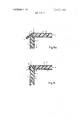
- FIGS. l3, 14, 14a and 15 are views similar to FIGS. 1 through 12 but showing additional modifications according to this invention.
- the body or hull 1 is a molded plastic unit of fiberglass or the like fiber-reinforced plastic and has an outer wall 4, a hard foam inter-layer and an inner wall 6.
- the walls 4 and 6 may be quite thin and the body or hull unit can be molded in half sections composed of the inner and outer layer or shell parts with the hardenable plastic foam interlayer 5 placed therebetween or injected under pressure and then hardened in place.
- the deck 2 is a component of the same type as the hull 1 including a thin outer wall 4', a hard foam interlayer 5' and a thin inner wall 6'.
- hull I and deck 2 are of very light and relatively thin construction, it is important that the two components be united by a rigid, strong, water-tight connection or seam that does not require additional fittings and which can be bonded together without difficulty, producing an integrated unitary boat body.
- connection joint or seam 3 is provided by forming a wedge-shaped tongue or upper edge 7 on the hull l with a relatively small angle of inclination.
- the outer layer 4 of the hull 1 is connected or merged with the inner layer 6 through the wedge-shaped wall section 7 which may converge to a pointed apex or terminate in a flat upper plane surface as shown.
- the deck 2 is provided with a bulged periphery or circumferential marginal portion which has a wedge-shaped groove 8 in the lower face thereof corresponding in shape to the wedge edge 7 of the boat hull and large enough to receive this edge 7.
- the outer layer 4 of the deck 2 is curved to form a circumferential outer edge 9 whereupon the outer layer 4' extends upwardly to form the outer wedge wall, then merges at the bottom of the groove 8 into the inner layer 6' of the deck which then extends downwardly to an inner edge 10, thereby defining the wedge-shaped groove 8.
- the inner edge 10 then extends upwardly and merges into the inner layer 6 of the deck 2.
- the interiors between the outer layer 4 of the deck and the inner layer 6' of the deck are filled with hard foam 5' which, of course, is sealed completely in the deck unit.
- the wedge-shaped edge 7 of the boat hull into the groove 8 of the deck 2 it is preferably coated with a hardenable plastic, glue or other adhesive and the two parts are then pressed together. Due to the wedge inclination of the walls, a firm bonding will result and any deviations from an accurate fitting shape will be corrected by the resiliency of the adjacent parts which is accommodated by having the foam interlayers 5 or 5 around the margins at least being somewhat resilient and flexible.
- the upper horizontal part of the edge 7 on the boat hull l is provided with a groove in the top end. thereof in the range where the inner-layer 6 merges with the outer layer 4 of the hull 1.
- the edge 7 of the hull l and the groove 8 of the deck have a circular, instead of a wedge-shaped configuration, and the inner edge 10 of the groove 8 will snap over the rounded bulge of the edge 7 as the parts are pressed together.
- the snap fit may be tight enough so that glue or other adhesive need not be used.
- a circumferential seal 11 in the form of a soft rubber strip, plastic or the like may be placed in the groove and surround the bulbous portion of the edge 7 as shown, thereby providing a cushion between the deck and hull.
- a reinforcement insert 12 composed of glass fibers, a fibrous mat, a metal rail, or the like can be embedded in the foam 5 just inwardly from the outer edge of the deck 5.
- FIG. 3a In the arrangement of FIG. 3a an inversion of the joint or seam is illustrated with the groove 8 formed in the boat body edge 7 and the circular bulge formed on the deck.
- the upper edge 7 of the boat body has a hook-like locking configuration l3 and the deck outer edge 9 has a corresponding profile so that the boat body edge 7 is hooked into the groove 8 of the deck.
- the undercut or hook-like projection 13 of the nested configurations may be designed so that a little resiliency of the components will permit the parts to be snapped together in locked relationship.
- an arrowhead projection 7 is formed on the hull and is received in a correspondingly-shaped recess 8 in the deck, thereby providing two hook-like locks 13, one on the outside and one on the inside.
- the inter-fitting edge and recess are provided with a series of barb-like projections 13 and recesses along the sides thereof.
- the contour of the recess 8 and the projection 7 is similar to the wedge arrangement of FIG. 1 with the barb and barb recesses being formed in the parts.
- an M-shaped edge .7 is provided seating in a corresponding contour 8 with the barb and groove arrangement 13 being provided to lock the two parts together.
- sealing bands can be interposed between the inter-mated parts.
- the hull 1 of the boat is reinforced with a central supporting rib 14 which is also connected with the deck 2 for a better stiffening of both the deck and hull.
- the rib 14 has an edge 7 similar to that shown in FIG. 6 and provided with the barbs, while the central portion of the bottom layer 4 of the deck has a mating groove 8 receiving the edge.
- the groove 8 is bounded by edges 15.
- the interlocking barb and groove or toothed arrangement provided by the edges and grooves of the FIG. 8 embodiment can be reinforced with glue or the mere elastic fit of the mating parts can be relied on to form the assembly.
- the joint configuration between the center rib 14 and the deck 2 is generally wedge-shaped.
- the boat hull is illustrated as having a center board slot 16 bounded by two walls 17.
- the edges 7 of these walls 17 have wedge surfaces or undercut surfaces as desired, fitting in mating grooves 8 in the deck 2 which has a slot that also registers with the slot 16.
- the periphery of the deck 2 can be provided with a tread portion 18 designed at an inclination of 45 with respect to the deck plane, and this can be provided in the region between the mast and rudder of the deck of a sailboat.
- the tread may extend over the deck surface as shown at 18' in FIG. 11, and a further tread surface 18" may also be provided on the inner periphery of the deck.
- the tread surfaces 18 and 18" strengthen the deck peripheries and further strengthening can be obtained by a laminate l9 embedded in the tread 18 or 19' embedded in the foam as shown in FIG. 11a.
- the upper edge of the hull l terminates in end edges 7 of the inner layer 6 and outer layer 4, and the foam interior 5 is exposed.
- the free end edges of the layers 4 and 6 are deformed or flattened outwardly from the foam layer 5. This flattening can be done by heating a boat hull composed of thermoplastic material around the peripheral edges thereof, or these outturned shapes can be made during initial production of the hull.
- the groove 8 in the bottom face of the deck 2 is correspondingly undercut to receive the outturned beads or flanges 7.
- the foam inner layer 5 may engage the bottom of the recess 8 and will be sufficiently resilient to permit the mating of the parts. Cement may be used to form a water-tight joint.
- the inner periphery of the deck 2 may have a downturned flange to rigidify the deck.
- the mating configuration of the edge 7 and recess 8 is sloped back from the periphery of the hull as shown, eliminating any ledge around the periphery of the hull which might offer resistance to water flow.
- the sloping contour could be initially molded into the deck and hull components or could be formed afterwards.
- connection joint or seam in deck and hull constructions composed of two fiberglass walls with an interspace therebetween filled with foam plastic.
- the peripheries of the walls lap over each other and are sealed with cement or the like.
- the four layers of walls are bent to conform into mating relationship as illustrated, and in the FIG. 15 embodiment the upper edges of the walls 4 and 6 of the hull 1 can' be exposed and seated in the recess 8 provided in the inner wall 6' of the deck.
- the bonded together configurations of the layers greatly stiffen the periphery of the deck.
- a shoulder 21 provides an added support for the deck.
- this invention provides tongue and groove joint or seam constructions for uniting deck and hull components of fiberglass boats and is especially useful where these components are composed of thin outer shells encasing a lightweight filling such as plastic foam, fiberglass or the like.
- a boat construction comprising a premolded spaced dual wall plastic hull, filled with rigid plastic foam, a pre-molded spaced, dual wall deck filled with rigid plastic foam the edges of said hull and deck being formed with interfitting and interlocking tongue and grooves interlocked with each other, said foam extending into and filling said tongue, said dual wall enveloping said groove and being filled with said foam around said groove to provide a reinforced wall structure around said groove.
- tongue and groove configurations include a tongue with a hook-like edge and a groove with a hook recess cooperating to interlock the tongue and groove together.
Abstract
Plastic boat hulls are connected to their decks through nested inter-fitting tongue and groove joint configurations which are bonded together by fusing, adhesives, or the like. The hull and deck are hollow molded plastic units filled with plastic foam. The units have thin fiberglass plastic type spaced parallel walls connected around the peripheries thereof by configurations which form the inter-fitting joint or seam so that the insert layer between the walls is never exposed and water-tight units are provided.
Description
United States Patent 1191 Stoeberl May 21, 1974 [5 BOAT HULL AND DECK ASSEMBLY 3,524,290 8/1970 Sarvay 52/396 x 3 O l 72 P 4 [76] Inventor: 3,232,220 4/1369 Eggslaett-Bachhamv Germany 3,701,214 10/1972 Sakamoto 46/26 Filed: Mar. 8, 1972 3,346,775 10/1967 Chrlstiansen 46/25 PP 232,329 Primary Examiner-George E. A. Halvosa Assistant Examiner-Edward Kazenske [30] Foreign Application priority Data Attorney, Agent, or Firm-Hill, Gross, Simpson, Van
Mar, 9, 1971 Germany 2111257 Same, Steadmam Chara & slmpso [52] US. .Cl. 9/6, 114/88 [57] ABSTRACT [51 Int. Cl B63!) 5/24 Plastic boat hulls am Connected to their decks throu h I l g [58] of Search H4/88 29/4531 nested inter-fitting tongue and groove joint configura- 52/595 46/25 26 tions which are bonded together by fusing, adhesives, or the like. The hull and deck are hollow molded plas- [56] References C'ted tic units filled with plastic foam. The units have thin UNITED STATES PATENTS fiberglass plastic type spaced parallel walls connected 3,531,809 10/1970 around the peripheries thereof by configurations 3,634,898 1/1972 which form the inter-fitting joint or seam so that the 3.625.808 /l Martin insert layer between the walls is never exposed and 3,364.64! Brenneman... water tight units are provided 3,291,088 12/1966 Klose 3,51 1,005 5/1970 MacMaster 52/595 X 11 Claims, 16 Drawing Figures 5 I 6 I "viii i ifiiji i 'fii 3N PATENTEBMAYZi I974 I 3 811 I41 sum 1 or 7 PATENTEDMAYZ] 1914 SHEEI 6 [IF 7 I Fig.13
s, Sq
Fig.1
BOAT HULL AND DECK ASSEMBLY BACKGROUND OF THE INVENTION between the hull and deck.
2. Description of the Prior Art Heretofore hull and deck sections of boats were joined with fasteners, added corner and edge members and the like, all of which added to the weight of the boat, increased its cost, and provided constructions which were not water-tight and would break and tear apart under deck loads. When the deck and hull components were composed of molded plastic layers with a hard foam inter-layer, the ends of the three layers were exposed and defeated attempts to satisfactorily cement the components together, due among other things to bulging of the layers under load which would break the bond and expose the interiors of the shells to water. The addition of longitudinal stringers and the like for reinforcing the area of connection or seam proved unsatisfactory because of the added expense and weight, which is a great disadvantage in racing sailboats.
SUMMARY OF THE INVENTION The present invention now provides waterproof reinforcing tongue and groove joint seams between the deck and hull components of boats and is especially useful when these components are composed of molded fiberglass type plastic hollow shells filled with a foam inter-layer.
According to this invention the peripheries of hollow molded fiberglass deck and hull units are shaped to form inter-fitting and preferably interlocking configurations which will cooperate to provide when bonded together a water-tight seam which reinforces the edge or corner between the deck and hull without adding to the weight thereof. The deck and hull components can be molded to desired shapes and contours including configurations for reinforcing struts, center board receiving slots, and the like.
The joint connections of this invention will accommodate deformations of the deck and hull components which can be appreciable in long and narrow boat bodies such as in catamarans. The interfitting joint or seam-forming configuration may be press fit together so that any glue or cement therebetween will be squeezed or pre-stressed and gluing clamps are not needed. In order to provide for the snap fitting of the peripheral edge configurations to form the seam, the foam inter-layer of the hollow deckand hull components may be resilient adjacent these configurations.
It is then an object of this invention to provide hull and deck components of boats with inter-fitting peripheral edges forming a reinforcing joint seam uniting the hull and deck.
A further object of this invention is to provide fiberglass boats composed of foam filled hollow hull and deck shells having inter-fitting peripheral configurations that are snapped together to provide a reinforcing water-tight seam.
A further object of the invention is to provide improved lightweight molded plastic boat constructions with edge configurations adapted to be snapped together to form rigidifying seams.
Another object of the invention is to provide a corner seam uniting the hull and deck of molded plastic boat components composed of shaped inter-fitting edge configurations on the components which when nested and bonded together provide a reinforced stifi connection without the use of other components.
A further object of the invention is to provide hollow molded plastic deck and bull components for boats which are filled with a plastic foam inter-layer and having interfitting peripheral edges easily bonded together to form water-tight reinforcing seams for the boat.
Other and further objects of this invention will be apparent to those skilled in this art from the following detailed description of the annexed sheets of drawings which show a number of preferred embodiments of the invention:
BRIEF DESCRIPTION OF THE DRAWINGS FIG. 10 is a view similar to FIGS. I through 9 butv showing a construction according to this invention for a boat having a center board slot;
FIGS. 11, 11a and 12 are views similar to FIGS. 1 through 10 but showing foot tread platforms on the deck;
FIGS. l3, 14, 14a and 15 are views similar to FIGS. 1 through 12 but showing additional modifications according to this invention.
DESCRIPTION OF THE PREFERRED EMBODIMENTS The reference numerals on the drawings have been used to identify the following components and features:
1 Boat body or hull 2 Deck 3 Connection joint or seam 4,4 Outer layer 5,5 Hard foam interlayer 6,6 Inner layer 7 Edge of the boat body or hull 8 Groove 9 Outer edge 10 Inner edge ll Seal or bond 12 Reinforcing insert 13 Undercut Central longitudinal supporting rib l5 Edges of the groove 16 Centerboard box slot 17 Ccntcrboard box wall I8,l8'.l8" Treads 19,19 Reinforcement laminate 20 Flange 21 Shoulder In FIG. 1 the boat body or hull 1 has a generally U- shaped cross-section as is customary on long racing boats. The hollow interior of the boat body 1 is covered by a deck 2 secured to the hull by a peripheral seam or 'oint 3. J The body or hull 1 is a molded plastic unit of fiberglass or the like fiber-reinforced plastic and has an outer wall 4, a hard foam inter-layer and an inner wall 6. The walls 4 and 6 may be quite thin and the body or hull unit can be molded in half sections composed of the inner and outer layer or shell parts with the hardenable plastic foam interlayer 5 placed therebetween or injected under pressure and then hardened in place.
The deck 2 is a component of the same type as the hull 1 including a thin outer wall 4', a hard foam interlayer 5' and a thin inner wall 6'.
Since the hull I and deck 2 are of very light and relatively thin construction, it is important that the two components be united by a rigid, strong, water-tight connection or seam that does not require additional fittings and which can be bonded together without difficulty, producing an integrated unitary boat body.
As shown in FIG. 2, the connection joint or seam 3 is provided by forming a wedge-shaped tongue or upper edge 7 on the hull l with a relatively small angle of inclination. As shown, the outer layer 4 of the hull 1 is connected or merged with the inner layer 6 through the wedge-shaped wall section 7 which may converge to a pointed apex or terminate in a flat upper plane surface as shown. The deck 2 is provided with a bulged periphery or circumferential marginal portion which has a wedge-shaped groove 8 in the lower face thereof corresponding in shape to the wedge edge 7 of the boat hull and large enough to receive this edge 7. Thus, the outer layer 4 of the deck 2 is curved to form a circumferential outer edge 9 whereupon the outer layer 4' extends upwardly to form the outer wedge wall, then merges at the bottom of the groove 8 into the inner layer 6' of the deck which then extends downwardly to an inner edge 10, thereby defining the wedge-shaped groove 8. The inner edge 10 then extends upwardly and merges into the inner layer 6 of the deck 2. The interiors between the outer layer 4 of the deck and the inner layer 6' of the deck are filled with hard foam 5' which, of course, is sealed completely in the deck unit.
For uniting the wedge-shaped edge 7 of the boat hull into the groove 8 of the deck 2, it is preferably coated with a hardenable plastic, glue or other adhesive and the two parts are then pressed together. Due to the wedge inclination of the walls, a firm bonding will result and any deviations from an accurate fitting shape will be corrected by the resiliency of the adjacent parts which is accommodated by having the foam interlayers 5 or 5 around the margins at least being somewhat resilient and flexible.
In the embodiment of FIG. 3, the upper horizontal part of the edge 7 on the boat hull l is provided with a groove in the top end. thereof in the range where the inner-layer 6 merges with the outer layer 4 of the hull 1. Also, in FIG. 3 the edge 7 of the hull l and the groove 8 of the deck have a circular, instead of a wedge-shaped configuration, and the inner edge 10 of the groove 8 will snap over the rounded bulge of the edge 7 as the parts are pressed together. The snap fit may be tight enough so that glue or other adhesive need not be used. To improve the water-tightness of the seal between the snapped-together parts, a circumferential seal 11 in the form of a soft rubber strip, plastic or the like may be placed in the groove and surround the bulbous portion of the edge 7 as shown, thereby providing a cushion between the deck and hull. As also shown in FIG. 3, a reinforcement insert 12 composed of glass fibers, a fibrous mat, a metal rail, or the like can be embedded in the foam 5 just inwardly from the outer edge of the deck 5.
In the arrangement of FIG. 3a an inversion of the joint or seam is illustrated with the groove 8 formed in the boat body edge 7 and the circular bulge formed on the deck.
In the embodiment of FIG. 4, the upper edge 7 of the boat body has a hook-like locking configuration l3 and the deck outer edge 9 has a corresponding profile so that the boat body edge 7 is hooked into the groove 8 of the deck. The undercut or hook-like projection 13 of the nested configurations may be designed so that a little resiliency of the components will permit the parts to be snapped together in locked relationship.
In the FIG. 5 embodiment, an arrowhead projection 7 is formed on the hull and is received in a correspondingly-shaped recess 8 in the deck, thereby providing two hook-like locks 13, one on the outside and one on the inside.
In the FIG. 6 embodiment, the inter-fitting edge and recess are provided with a series of barb-like projections 13 and recesses along the sides thereof. The contour of the recess 8 and the projection 7 is similar to the wedge arrangement of FIG. 1 with the barb and barb recesses being formed in the parts.
In the FIG. 7 embodiment, an M-shaped edge .7 is provided seating in a corresponding contour 8 with the barb and groove arrangement 13 being provided to lock the two parts together. In addition, sealing bands can be interposed between the inter-mated parts.
As shown in FIGS. 8 and 9, the hull 1 of the boat is reinforced with a central supporting rib 14 which is also connected with the deck 2 for a better stiffening of both the deck and hull. As shown in FIG. 8, the rib 14 has an edge 7 similar to that shown in FIG. 6 and provided with the barbs, while the central portion of the bottom layer 4 of the deck has a mating groove 8 receiving the edge. The groove 8 is bounded by edges 15. The interlocking barb and groove or toothed arrangement provided by the edges and grooves of the FIG. 8 embodiment can be reinforced with glue or the mere elastic fit of the mating parts can be relied on to form the assembly.
In the FIG. 9 embodiment the joint configuration between the center rib 14 and the deck 2 is generally wedge-shaped.
In FIG. 10, the boat hull is illustrated as having a center board slot 16 bounded by two walls 17. The edges 7 of these walls 17 have wedge surfaces or undercut surfaces as desired, fitting in mating grooves 8 in the deck 2 which has a slot that also registers with the slot 16.
In FIG. 11 and 11a, the periphery of the deck 2 can be provided with a tread portion 18 designed at an inclination of 45 with respect to the deck plane, and this can be provided in the region between the mast and rudder of the deck of a sailboat. The tread may extend over the deck surface as shown at 18' in FIG. 11, and a further tread surface 18" may also be provided on the inner periphery of the deck. The tread surfaces 18 and 18" strengthen the deck peripheries and further strengthening can be obtained by a laminate l9 embedded in the tread 18 or 19' embedded in the foam as shown in FIG. 11a.
In the FIG. 11a embodiment, the upper edge of the hull l terminates in end edges 7 of the inner layer 6 and outer layer 4, and the foam interior 5 is exposed. The free end edges of the layers 4 and 6 are deformed or flattened outwardly from the foam layer 5. This flattening can be done by heating a boat hull composed of thermoplastic material around the peripheral edges thereof, or these outturned shapes can be made during initial production of the hull. The groove 8 in the bottom face of the deck 2 is correspondingly undercut to receive the outturned beads or flanges 7. During assembly the foam inner layer 5 may engage the bottom of the recess 8 and will be sufficiently resilient to permit the mating of the parts. Cement may be used to form a water-tight joint.
As also shown in FIG. Ila, the inner periphery of the deck 2 may have a downturned flange to rigidify the deck.
In the FIG. 12 embodiment, the mating configuration of the edge 7 and recess 8 is sloped back from the periphery of the hull as shown, eliminating any ledge around the periphery of the hull which might offer resistance to water flow. The sloping contour could be initially molded into the deck and hull components or could be formed afterwards.
In FIGS. 13 through 15, various additional configurations are provided to form the connection joint or seam in deck and hull constructions composed of two fiberglass walls with an interspace therebetween filled with foam plastic. The peripheries of the walls lap over each other and are sealed with cement or the like. The four layers of walls are bent to conform into mating relationship as illustrated, and in the FIG. 15 embodiment the upper edges of the walls 4 and 6 of the hull 1 can' be exposed and seated in the recess 8 provided in the inner wall 6' of the deck.
In the embodiments of FIGS. l3, l4 and 14a, the bonded together configurations of the layers greatly stiffen the periphery of the deck. In the FIG. 14 arrangement, a shoulder 21 provides an added support for the deck.
From the above descriptions it will, therefore, be understood that this invention provides tongue and groove joint or seam constructions for uniting deck and hull components of fiberglass boats and is especially useful where these components are composed of thin outer shells encasing a lightweight filling such as plastic foam, fiberglass or the like.
I claim as my invention:
1. A boat construction comprising a premolded spaced dual wall plastic hull, filled with rigid plastic foam, a pre-molded spaced, dual wall deck filled with rigid plastic foam the edges of said hull and deck being formed with interfitting and interlocking tongue and grooves interlocked with each other, said foam extending into and filling said tongue, said dual wall enveloping said groove and being filled with said foam around said groove to provide a reinforced wall structure around said groove.
2. The boat construction of claim 1 wherein the tongue and groove are wedge-shaped.
3. The boat construction of claim 1 wherein the tongue and groove are snap-fitted together.
4. The boat construction of claim 1 including an elastic sealing band between the tongue and groove.
5. The boat construction of claim 1 wherein the hull has a centerboard slot defined by side walls, the deck overlies the side walls and has a registering slot therethrough and the deck adjacent the registering slot together with the side walls having interfitting tongue and groove configurations.
6. The boat construction of claim 1 wherein the tongue and groove configuration is a cylindrical bulge on one of the components and a cylindrical recess in the other component.
7. The boat construction of claim 1 wherein the tongue and groove configurations include a tongue with a hook-like edge and a groove with a hook recess cooperating to interlock the tongue and groove together.
8. The boat construction of claim 1 wherein the tongue and groove are arrowhead-shaped.
9. The boat construction of claim 1 wherein the tongue and groove have complementary barbs and recesses along the sides thereof to interlock together.
10. The boat construction of claim 1 wherein the hull has a wedge-shape tongue around the periphery thereof and the deck has a mating wedge-shape recess receiving said tongue.
11. The boat construction of claim 1 wherein the hull has a tongue around the periphery thereof with a series of barb-like projections and the deck has a groove re ceiving said tongue and having barb recesses receiving said projections.
Claims (11)
1. A boat construction comprising a premolded spaced dual wall plastic hull, filled with rigid plastic foam, a pre-molded spaced, dual wall deck filled with rigid plastic foam the edges of said hull and deck being formed with interfitting and interlocking tongue and grooves interlocked with each other, said foam extending into and filling said tongue, said dual wall enveloping said groove and being filled with said foam around said groove to provide a reinforced wall structure around said groove.
2. The boat construction of claim 1 wherein the tongue and groove are wedge-shaped.
3. The boat construction of claim 1 wherein the tongue and groove are snap-fitted together.
4. The boat construction of claim 1 including an elastic sealing band between the tongue and groove.
5. The boat construction of claim 1 wherein the hull has a centerboard slot defined by side walls, the deck overlies the side walls and has a registering slot therethrough and the deck adjacent the registering slot together with the side walls having interfitting tongue and groove configurations.
6. The boat construction of claim 1 wherein the tongue and groove configuration is a cylindrical bulge on one of the components and a cylindrical recess in the other component.
7. The boat construction of claim 1 wherein the tongue and groove configurations include a tongue with a hook-like edge and a groove with a hook recess cooperating to interlock the tongue and groove together.
8. The boat construction of claim 1 wherein the tongue and groove are arrowhead-shaped.
9. The boat construction of claim 1 wherein the tongue and groove have complementary barbs and recesses along the sides thereof to interlock together.
10. The boat construction of claim 1 wherein the hull has a wedge-shape tongue around the periphery thereof and the deck has a mating wedge-shape recess receiving said tongue.
11. The boat construction of claim 1 wherein the hull has a tongue around the periphery thereof with a series of barb-like projections and the deck has a groove receiving said tongue and having barb recesses receiving said projections.
Applications Claiming Priority (1)
| Application Number | Priority Date | Filing Date | Title |
|---|---|---|---|
| DE2111257A DE2111257B2 (en) | 1971-03-09 | 1971-03-09 | Tongue and groove connection between the deck and the hull shell of a plastic hull |
Publications (1)
| Publication Number | Publication Date |
|---|---|
| US3811141A true US3811141A (en) | 1974-05-21 |
Family
ID=5800969
Family Applications (1)
| Application Number | Title | Priority Date | Filing Date |
|---|---|---|---|
| US00232829A Expired - Lifetime US3811141A (en) | 1971-03-09 | 1972-03-08 | Boat hull and deck assembly |
Country Status (6)
| Country | Link |
|---|---|
| US (1) | US3811141A (en) |
| AT (1) | AT323592B (en) |
| CH (1) | CH550683A (en) |
| DE (1) | DE2111257B2 (en) |
| FR (1) | FR2129549A5 (en) |
| GB (1) | GB1383237A (en) |
Cited By (32)
| Publication number | Priority date | Publication date | Assignee | Title |
|---|---|---|---|---|
| US4021874A (en) * | 1973-04-18 | 1977-05-10 | Coast Catamaran Corporation | Boat hull |
| US4094027A (en) * | 1977-05-09 | 1978-06-13 | Vernon Eugene G | Interlocking two piece hull for a catamaran |
| US4158082A (en) * | 1977-07-27 | 1979-06-12 | Bruce Belousofsky | Laminated ferro-cement structures and method of fabrication |
| US4418634A (en) * | 1981-10-23 | 1983-12-06 | Gerbus Leo H | Marine float |
| US4458623A (en) * | 1982-05-07 | 1984-07-10 | Skandinaviska Aluminium Profiler A.B. | Boat hull |
| US4552085A (en) * | 1983-01-24 | 1985-11-12 | Theodor Eder | Planking assembly and method of making same |
| US4559891A (en) * | 1982-07-26 | 1985-12-24 | Shorter Jr Myron L | Pontoon |
| US5377613A (en) * | 1993-06-29 | 1995-01-03 | The Untied States Of America As Represented By The Secretary Of The Navy | Submersible boat |
| US5556498A (en) * | 1994-12-19 | 1996-09-17 | Roamer Corporation | Method of manufacturing a recreational vehicle cabin |
| US5738747A (en) * | 1994-12-19 | 1998-04-14 | Roamer Corporation | Method of manufacturing a recreational vehicle cabin |
| US5743203A (en) * | 1996-04-03 | 1998-04-28 | Outboard Marine Corporation | Boat hull and deck assembly |
| US6170425B1 (en) | 1999-07-14 | 2001-01-09 | Hitech Ultralight Catamaran, Ltd. | Boat hull construction and method of making the same |
| US6213042B1 (en) | 1999-03-01 | 2001-04-10 | Barry E. Delfosse | Small waterplane area multihull (SWAMH) vessel with submerged turbine drive |
| EP1157922A2 (en) * | 2000-05-24 | 2001-11-28 | Jean Michel Martinez | Method for binding elements of a GRP hull |
| US6394014B1 (en) | 2000-09-12 | 2002-05-28 | William L. Waldock | Marine vessel and method of manufacturing |
| US6470817B2 (en) | 1999-03-01 | 2002-10-29 | Barry E. Delfosse | Small waterplane area multihull (SWAMH) vessel |
| US20040005825A1 (en) * | 2001-01-10 | 2004-01-08 | Hasted Ronald Francis | Board-like sportscraft |
| US20050006823A1 (en) * | 2003-07-09 | 2005-01-13 | Michael Merrick | Systems and methods for fabricating composite fiberglass laminate articles |
| US20060032422A1 (en) * | 2004-07-16 | 2006-02-16 | Mcdermott John M | Buoyant storage vessel |
| US20060162279A1 (en) * | 2002-11-30 | 2006-07-27 | Det Norske Veritas | Vessel structures and structures in marine vessels |
| EP1779991A1 (en) * | 2005-10-28 | 2007-05-02 | Dow Corning Corporation | Sealing for an automotive lamp |
| US20070110976A1 (en) * | 2005-06-09 | 2007-05-17 | Pastore Christopher M | Vandalism-resistant insulating panel for building exteriors and building having vandalism-resistant thermally insulative walls |
| WO2009145689A1 (en) * | 2008-05-26 | 2009-12-03 | Försvarets Materielverk | Boat hull comprising two composite materials |
| EP2199064A1 (en) * | 2007-09-11 | 2010-06-23 | Toray Industries, Inc. | Composite shaped article and process for manufacturing the same |
| US20110300766A1 (en) * | 2009-02-17 | 2011-12-08 | Lawrence Carbary | Silicone Gel Seal And Method For Its Preparation And Use |
| WO2012149626A1 (en) * | 2010-09-23 | 2012-11-08 | Roberts Wallace | Modular boat hull holds and method of making boat hulls using same |
| CN102963493A (en) * | 2012-12-07 | 2013-03-13 | 山东大学 | Composite plastic boat body and compression molding method thereof |
| CN104283168A (en) * | 2014-10-31 | 2015-01-14 | 向荣集团有限公司 | Efficient waterproof assembly for bus |
| US20190120270A1 (en) * | 2016-06-15 | 2019-04-25 | Bayerische Motoren Werke Aktiengesellschaft | Method for Connecting Two Components, and Component Arrangement |
| US10513313B1 (en) * | 2018-12-12 | 2019-12-24 | Douglas R. Hunter | Foam core barge and method of assembly |
| WO2020225382A1 (en) * | 2019-05-07 | 2020-11-12 | Robert Zimmermann | Floating carrier device |
| WO2021071569A1 (en) * | 2019-06-05 | 2021-04-15 | Ohare Christopher Francis | Method and apparatus for improved handling and attachment of living sessile organisms to substrate and habitat enhancement |
Families Citing this family (3)
| Publication number | Priority date | Publication date | Assignee | Title |
|---|---|---|---|---|
| FR2509685A2 (en) * | 1976-08-17 | 1983-01-21 | Sodistra | Boat for navigating rivers - has hull bottom and side panels of cellular plastics material coated with stratified plastics |
| DE3839805A1 (en) * | 1988-11-25 | 1990-05-31 | Gerhard Rambacher | Surfboard |
| RU2738944C2 (en) * | 2019-02-27 | 2020-12-18 | Александр Александрович Тараненко | Method of t-like connection of three-layer ship structures from polymer composite material and obtained by this method connection unit |
Citations (11)
| Publication number | Priority date | Publication date | Assignee | Title |
|---|---|---|---|---|
| US3291088A (en) * | 1965-10-24 | 1966-12-13 | Klose Hans-Peter | Multi-purpose boat |
| US3346775A (en) * | 1965-06-19 | 1967-10-10 | Interlego Ag | Components for making structures comprising electrical circuits |
| US3364641A (en) * | 1966-10-12 | 1968-01-23 | John H. Brenneman | Floating spline seat |
| US3435470A (en) * | 1967-08-07 | 1969-04-01 | Leo M Krenzler | Foam-filled boat hull |
| US3511005A (en) * | 1968-01-22 | 1970-05-12 | Gordon Macmaster | Building construction |
| US3524290A (en) * | 1968-06-18 | 1970-08-18 | Standard Products Co | Receiver for spline-type gaskets |
| US3531809A (en) * | 1968-10-11 | 1970-10-06 | Larson Ind Inc | Plastic boat construction |
| US3625808A (en) * | 1969-09-29 | 1971-12-07 | Martin Fireproofing Corp | Composite concrete and cement-wood fiber plank |
| US3634898A (en) * | 1970-04-23 | 1972-01-18 | Larson Ind Inc | Plastic boat construction |
| US3635280A (en) * | 1969-11-07 | 1972-01-18 | John T Parsons | Self-aligned multipart combustible casting pattern and method of making same |
| US3701214A (en) * | 1970-12-22 | 1972-10-31 | Kyoikushuppan Co Ltd | Flexible, soft, foam resin assembling pieces |
-
1971
- 1971-03-09 DE DE2111257A patent/DE2111257B2/en not_active Withdrawn
-
1972
- 1972-02-29 GB GB934172A patent/GB1383237A/en not_active Expired
- 1972-03-02 CH CH302872A patent/CH550683A/en not_active IP Right Cessation
- 1972-03-07 AT AT188972A patent/AT323592B/en not_active IP Right Cessation
- 1972-03-08 US US00232829A patent/US3811141A/en not_active Expired - Lifetime
- 1972-03-09 FR FR7208215A patent/FR2129549A5/fr not_active Expired
Patent Citations (11)
| Publication number | Priority date | Publication date | Assignee | Title |
|---|---|---|---|---|
| US3346775A (en) * | 1965-06-19 | 1967-10-10 | Interlego Ag | Components for making structures comprising electrical circuits |
| US3291088A (en) * | 1965-10-24 | 1966-12-13 | Klose Hans-Peter | Multi-purpose boat |
| US3364641A (en) * | 1966-10-12 | 1968-01-23 | John H. Brenneman | Floating spline seat |
| US3435470A (en) * | 1967-08-07 | 1969-04-01 | Leo M Krenzler | Foam-filled boat hull |
| US3511005A (en) * | 1968-01-22 | 1970-05-12 | Gordon Macmaster | Building construction |
| US3524290A (en) * | 1968-06-18 | 1970-08-18 | Standard Products Co | Receiver for spline-type gaskets |
| US3531809A (en) * | 1968-10-11 | 1970-10-06 | Larson Ind Inc | Plastic boat construction |
| US3625808A (en) * | 1969-09-29 | 1971-12-07 | Martin Fireproofing Corp | Composite concrete and cement-wood fiber plank |
| US3635280A (en) * | 1969-11-07 | 1972-01-18 | John T Parsons | Self-aligned multipart combustible casting pattern and method of making same |
| US3634898A (en) * | 1970-04-23 | 1972-01-18 | Larson Ind Inc | Plastic boat construction |
| US3701214A (en) * | 1970-12-22 | 1972-10-31 | Kyoikushuppan Co Ltd | Flexible, soft, foam resin assembling pieces |
Cited By (45)
| Publication number | Priority date | Publication date | Assignee | Title |
|---|---|---|---|---|
| US4021874A (en) * | 1973-04-18 | 1977-05-10 | Coast Catamaran Corporation | Boat hull |
| US4094027A (en) * | 1977-05-09 | 1978-06-13 | Vernon Eugene G | Interlocking two piece hull for a catamaran |
| US4158082A (en) * | 1977-07-27 | 1979-06-12 | Bruce Belousofsky | Laminated ferro-cement structures and method of fabrication |
| US4418634A (en) * | 1981-10-23 | 1983-12-06 | Gerbus Leo H | Marine float |
| US4458623A (en) * | 1982-05-07 | 1984-07-10 | Skandinaviska Aluminium Profiler A.B. | Boat hull |
| US4559891A (en) * | 1982-07-26 | 1985-12-24 | Shorter Jr Myron L | Pontoon |
| US4552085A (en) * | 1983-01-24 | 1985-11-12 | Theodor Eder | Planking assembly and method of making same |
| USRE36093E (en) * | 1993-06-29 | 1999-02-16 | The United States Of America As Represented By The Secretary Of The Navy | Submersible boat |
| US5377613A (en) * | 1993-06-29 | 1995-01-03 | The Untied States Of America As Represented By The Secretary Of The Navy | Submersible boat |
| US5556498A (en) * | 1994-12-19 | 1996-09-17 | Roamer Corporation | Method of manufacturing a recreational vehicle cabin |
| US5738747A (en) * | 1994-12-19 | 1998-04-14 | Roamer Corporation | Method of manufacturing a recreational vehicle cabin |
| US5743203A (en) * | 1996-04-03 | 1998-04-28 | Outboard Marine Corporation | Boat hull and deck assembly |
| US6213042B1 (en) | 1999-03-01 | 2001-04-10 | Barry E. Delfosse | Small waterplane area multihull (SWAMH) vessel with submerged turbine drive |
| US6470817B2 (en) | 1999-03-01 | 2002-10-29 | Barry E. Delfosse | Small waterplane area multihull (SWAMH) vessel |
| US6170425B1 (en) | 1999-07-14 | 2001-01-09 | Hitech Ultralight Catamaran, Ltd. | Boat hull construction and method of making the same |
| EP1157922A2 (en) * | 2000-05-24 | 2001-11-28 | Jean Michel Martinez | Method for binding elements of a GRP hull |
| EP1157922A3 (en) * | 2000-05-24 | 2001-12-19 | Jean Michel Martinez | Method for binding elements of a GRP hull |
| US6394014B1 (en) | 2000-09-12 | 2002-05-28 | William L. Waldock | Marine vessel and method of manufacturing |
| US20040005825A1 (en) * | 2001-01-10 | 2004-01-08 | Hasted Ronald Francis | Board-like sportscraft |
| US20060162279A1 (en) * | 2002-11-30 | 2006-07-27 | Det Norske Veritas | Vessel structures and structures in marine vessels |
| US7112299B2 (en) | 2003-07-09 | 2006-09-26 | Michael Merrick | Systems and methods for fabricating composite fiberglass laminate articles |
| US20050006823A1 (en) * | 2003-07-09 | 2005-01-13 | Michael Merrick | Systems and methods for fabricating composite fiberglass laminate articles |
| US8017054B1 (en) | 2003-07-09 | 2011-09-13 | Michael Merrick | Systems and methods for fabricating composite fiberglass laminate articles |
| US20060032422A1 (en) * | 2004-07-16 | 2006-02-16 | Mcdermott John M | Buoyant storage vessel |
| US20070110976A1 (en) * | 2005-06-09 | 2007-05-17 | Pastore Christopher M | Vandalism-resistant insulating panel for building exteriors and building having vandalism-resistant thermally insulative walls |
| US7521114B2 (en) * | 2005-06-09 | 2009-04-21 | Philadelphia University | Vandalism-resistant insulating panel for building exteriors and building having vandalism-resistant thermally insulative walls |
| US20090194231A1 (en) * | 2005-06-09 | 2009-08-06 | Philadelphia University | Vandalism-resistant insulating panels for building exteriors and building having vandalism-resistant thermally insulative walls |
| US8287671B2 (en) | 2005-06-09 | 2012-10-16 | Philadelphia University | Vandalism-resistant insulating panels for building exteriors and building having vandalism-resistant thermally insulative walls |
| EP1779991A1 (en) * | 2005-10-28 | 2007-05-02 | Dow Corning Corporation | Sealing for an automotive lamp |
| US8173238B2 (en) | 2007-09-11 | 2012-05-08 | Toray Industries, Inc. | Composite shaped article and process for manufacturing the same |
| EP2199064A1 (en) * | 2007-09-11 | 2010-06-23 | Toray Industries, Inc. | Composite shaped article and process for manufacturing the same |
| US20110008566A1 (en) * | 2007-09-11 | 2011-01-13 | Toray Industries ,Inc. | Composite shaped article and process for manufacturing the same |
| EP2199064A4 (en) * | 2007-09-11 | 2011-03-23 | Toray Industries | Composite shaped article and process for manufacturing the same |
| WO2009145689A1 (en) * | 2008-05-26 | 2009-12-03 | Försvarets Materielverk | Boat hull comprising two composite materials |
| US20110300766A1 (en) * | 2009-02-17 | 2011-12-08 | Lawrence Carbary | Silicone Gel Seal And Method For Its Preparation And Use |
| WO2012149626A1 (en) * | 2010-09-23 | 2012-11-08 | Roberts Wallace | Modular boat hull holds and method of making boat hulls using same |
| US8931752B2 (en) * | 2010-09-23 | 2015-01-13 | Wallace Martin ROBERTS | Modular boat hull molds and method of making boat hulls using same |
| CN102963493A (en) * | 2012-12-07 | 2013-03-13 | 山东大学 | Composite plastic boat body and compression molding method thereof |
| CN102963493B (en) * | 2012-12-07 | 2015-07-08 | 山东大学 | Composite plastic boat body and compression molding method thereof |
| CN104283168A (en) * | 2014-10-31 | 2015-01-14 | 向荣集团有限公司 | Efficient waterproof assembly for bus |
| US20190120270A1 (en) * | 2016-06-15 | 2019-04-25 | Bayerische Motoren Werke Aktiengesellschaft | Method for Connecting Two Components, and Component Arrangement |
| US11009057B2 (en) * | 2016-06-15 | 2021-05-18 | Bayerische Motoren Werke Aktiengesellschaft | Method for connecting two components, and component arrangement |
| US10513313B1 (en) * | 2018-12-12 | 2019-12-24 | Douglas R. Hunter | Foam core barge and method of assembly |
| WO2020225382A1 (en) * | 2019-05-07 | 2020-11-12 | Robert Zimmermann | Floating carrier device |
| WO2021071569A1 (en) * | 2019-06-05 | 2021-04-15 | Ohare Christopher Francis | Method and apparatus for improved handling and attachment of living sessile organisms to substrate and habitat enhancement |
Also Published As
| Publication number | Publication date |
|---|---|
| AT323592B (en) | 1975-07-25 |
| DE2111257A1 (en) | 1972-09-14 |
| DE2111257B2 (en) | 1974-02-07 |
| CH550683A (en) | 1974-06-28 |
| FR2129549A5 (en) | 1972-10-27 |
| GB1383237A (en) | 1975-02-05 |
Similar Documents
| Publication | Publication Date | Title |
|---|---|---|
| US3811141A (en) | Boat hull and deck assembly | |
| US3840926A (en) | Boat hull | |
| US3435470A (en) | Foam-filled boat hull | |
| US4457249A (en) | Method of fabricating an integral shell formed body and the body formed thereby | |
| US8403593B2 (en) | Rig mat system using panels of composite material | |
| JPS6356862B2 (en) | ||
| AU640190B2 (en) | Inflatable boat and deck therefore | |
| US4142265A (en) | Plastics boat hull | |
| US3640798A (en) | Composite structural core assembly | |
| CA1205331A (en) | Planking assembly and method of making same | |
| US4405669A (en) | Laminate reinforcement for fibre-reinforced synthetic resins | |
| US3372408A (en) | Sectional boat structure | |
| US2721341A (en) | Dual-welt plastic ship | |
| US3599257A (en) | Canoe and method of construction thereof | |
| US3329174A (en) | Lined hollow wood body | |
| US2905579A (en) | Shell construction and method of making the same | |
| US3126557A (en) | Boat construction | |
| EP0048055A2 (en) | Laminate reinforcement for fibre-reinforced synthetic resins | |
| US5634425A (en) | Boat hull including moulded shell structure | |
| US2269685A (en) | Diaphragm | |
| JP2006089013A (en) | Deflection prevention material, its manufacturing method and frp structure using the deflection prevention material | |
| US20100297897A1 (en) | inflatable liferaft | |
| US4131962A (en) | Ribbed inner shell for a hull of a catamaran | |
| US3220027A (en) | Boat hull constructions | |
| JPH0215637Y2 (en) |