US397975A - Apparatus - Google Patents
Apparatus Download PDFInfo
- Publication number
- US397975A US397975A US397975DA US397975A US 397975 A US397975 A US 397975A US 397975D A US397975D A US 397975DA US 397975 A US397975 A US 397975A
- Authority
- US
- United States
- Prior art keywords
- circuit
- magnet
- strip
- stamps
- opening
- Prior art date
- Legal status (The legal status is an assumption and is not a legal conclusion. Google has not performed a legal analysis and makes no representation as to the accuracy of the status listed.)
- Expired - Lifetime
Links
- 210000003371 Toes Anatomy 0.000 description 12
- 230000035611 feeding Effects 0.000 description 12
- PXHVJJICTQNCMI-UHFFFAOYSA-N nickel Chemical compound [Ni] PXHVJJICTQNCMI-UHFFFAOYSA-N 0.000 description 8
- 239000011435 rock Substances 0.000 description 8
- 230000000994 depressed Effects 0.000 description 4
- 229910052759 nickel Inorganic materials 0.000 description 4
- 240000001439 Opuntia Species 0.000 description 2
- 101700058227 POLI Proteins 0.000 description 2
- 238000009825 accumulation Methods 0.000 description 2
- 238000010276 construction Methods 0.000 description 2
- 238000010586 diagram Methods 0.000 description 2
- 230000000694 effects Effects 0.000 description 2
- 238000003780 insertion Methods 0.000 description 2
- 239000011810 insulating material Substances 0.000 description 2
- 230000001788 irregular Effects 0.000 description 2
- 230000000284 resting Effects 0.000 description 2
Images


Classifications
-
- G—PHYSICS
- G07—CHECKING-DEVICES
- G07F—COIN-FREED OR LIKE APPARATUS
- G07F5/00—Coin-actuated mechanisms; Interlocks
- G07F5/10—Coin-actuated mechanisms; Interlocks actuated electrically by the coin, e.g. by a single coin
Definitions
- This invention relates to that class of auto matic vending apparatus in which the deposit ofa coin of the proper denomination in the apparatus sets in motion suitable mechanism for automatically ejecting or delivering the goods in position to be taken by the purchaser, thus avoiding the necessity of the services of a. salesman.
- the apparatus constituting the invention is especially design ed for the automatic vending of postage-stamps, railway-tickets, accidentinsurance policies, and similar things which are or may be prepared and put up in the form of long strips and wound 11130113 reel or spool.
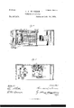
- FIG. 1 is a side elevation ofv the working parts of the apparatus, one side of the casing being removed.
- Fig. 2 is a sectional elevation' of the same.
- Fig. 3 is a side elevation, partly in section, showing the side of the apparatus opposite that shown in Fig. 1.
- Fig. 4 is a horizontal section taken on substantially the line 4: of Fig. 9. view taken on substantially the line 5 of the same figure.
- Fig. '6 is an enlarged view of a part of Fig. i. Fig.
- FIG. 7 is a cross-section of the parts shown in Fig. 6, taken on the line 7 of E be located beneath the hoodand the opening said figure.
- Figs. 8 to 11 illustrate details which will be hereinafter referred to, Fig. 8 being a view of the circuit-closer for closing the circuit through the releasing-magnet; Fig. 9, a view of the feeding-magnet; Fig. 10, a view of the circuit-breaker for breaking the circuit through the stop-magnet, and Fig. 11
- FIG. 12 is a diagram illustrating the Fig. 5 is a similar Serial No. 280,107. (No model.)
- the postage-stamps,tickets, or other articles A which are to be vended, are prepared in the form of a long strip, and are wound upon a spool, B, mounted to turn freely upon a spindle, 50, supported upon the framework.
- the strip A will hereinafter be referred to as comprising postage-stamps.
- the stamps A are led from the spool B, and after passing above a support, 49, are led between a pair of feeding-rolls, i8 i7, and are projected through an opening, it, in the front of the apparatus.
- the feed roll 48 is positively driven to advance the proper n umber of stamps through the opening lii in a manner which will be hereinafter explained, and in order to secure a more positive feed of the stamps it is provided with one or more series of points, 9, which give it a more positive feeding action.
- the companion roll 47 revolves by frictional contact, and is pressed against the roll 48 by means of springs 10, which bear upon its journals.
- a cutting-blade 45, WlllGllTlS provided with a suitable handle, 44, projecting at the side of. the apparatus, and
- the blade 45 is normally held in its raised position, so as not to obstruct the opening 46, by means of a spring, 39.
- the opening 46 will preferably be covered by a downwardly-opening hood, 43, which will conceal the opening and the cutting-blade, and there will also, preferably,
- This opening communicates with an inclined chute, 40, which extends to the rear part of the apparatus and terminates in position to discharge the coins into a hopper, 51, ar-
- the bottom portion of the inner end of the chute it) is composed of a tilting table, 38, over which the coinsmust pass as they arrive at the end of the chute, and from which they are discharged into the hopper.
- the table 38 is supported upon an arm, 37, extending from a rock-shaft, 334.3, which is n'ovidt-u'l with an arm, 35, carrying a weight, 34, which is so adjusted as to just counterbalance the weigl-it of the table 38 and hold itin its raised position, but which will not be sufficient to prevent the tilting of the table by the weight of the coin passing over it.
- the shaft 36 also carries a U-shaped 2o circuit-closer,33, (see Fig.
- the magnet C is provided with an armature, 32, which is pivoted as indicated at 31, and is provided with a suitable 5 retractile, 30.
- the armature 32 is connected to a vertical rod, 29, which is pivoted to the armature, so as to have a slight rocking movement between stops 2, and is acted on by a spring, 12, so as to be normally pressed in- 0 ward against its inner stop.
- the rod 29 is provided with an inward lateral projection, :29, which is acted on by av back-stop, 25, to. limit. the upward movement.
- a toe 3 which is so an- 15' rangedthat as the rod is drawn downward by the movement of the armature 32 it will engage with a. toe, i, projecting from a rockshaft, 28, having an arm, 27, to which is secured.
- the bins 5 are provided at their-up.
- stamps isprovidedqwit'h the usual transverse rows of perforations, 1i, marking the lines of. division between the several stamps, and the stripcomprises other artic1essuch as tickets or insurance; policies instead of. stamps-then the individual. ticket-s or'poli; cies will be separated by rows of si1nilarrperforations.
- each of the springs is fixed upon but insulated from a crossbar, 113, while the opposite end is free to be movedxup and down by the action of the pins 5.
- the two outer springs of the seriesv are connected. at their fixed ends by wires 17 with the contact-points '7, or. with the circuit (i upon opposite sides of the contact-points 7
- the intermediate springs, 15, are also electrically connected at their fixed ends in pairs, indicated. Located above the free ends of the springs 15 are insulated con tact-plates 18, which.
- the springs 15 form av series of circuit-closers which areincluded in the circuit 6 to 17, and so arranged that when all of the springs are raised by the pins 5 the circuit will be closed, and that whenever any one of the pins, 5 is allowed to. fall so as to disconnect its sprin from the contact-plate 1.8 the circuit 6 to l I will be broken.
- the contactqioints 8, before referred to, are includediin a.
- branch circuit, 19, whichconnects with one of the outside sprin gs 15- and with the circuit 6 betweenv the rel'eas.- ing-nragnets and the battery, as: indicated at a in Fig. 12, and includes an electroanagnet, E, termed, for convenience, the li'eedin g-lnagnet.
- The. armature 52. ot' the magnet Eis. provided with an: arm, 54-, which carries a. spring-pressed pawl, 53, which engages: witha ratchet, 55', fixed upon. the shaft'of the feedrolllS in such manner that as the armature is vibrated-by the energizing'of the magnet the roll 458 will be operated to advance the strip of stamps.
- the circuit. 1 9, which includes the m agnet is; provided with an automatic circuit closer andnhreaker, 56, (see Fi g. 9,);which is supported upon the bracketed which supports themag net,,and is operated through an adjustable p;oint,57, carried by the armature in theusnasl manner, to break. the circuit as soon as. the magnet; is: energized an d has attracted its armature, and to close the circuit and re energize the. magnet as soon as the arnlatureis Per? tracted, the retraction of the armature being accomplished by means of a retractile, 58.
- the armature 52 will also, preferably, be provided with a striker, 59, which as the armature is vibrated will strike upon a gong, 60, and thus give notice that the apparatus is being operated.
- the shaft of the roll 48 is provided with one or more arms, 20, which, as the shaft is revolved, come into engagement with the pivoted lug 21, carried upon the side of the bar 29, in such manner as to rock the bar outward and carry the toe 3 out of engagement with the toe at, thereby allowing the plate 26 to rock downward away from the heads of the bins 5.
- the gate 61 is acted upon by a stud, 62, extending from the end of a lever, 63, the opposite end of which is arranged to be engaged by a catch, 64, carried by the armature (35 of an electro-magnet, G, which I call the stop-magnet. ranged that so long as the catch 64. remains in engagement with the lever 63 the gate 61 will be elevated so as to leave the opening all unobstructed, and that whenever the catch Ul is disengaged from. the lever the latter will be rocked by its own weight so as to allow the gate 61 to fall and close the opening 41.
- a circuit-closer (38, (see Fig. 10,) which is operated by the lever i in such manner as to close the circuit through the branch 67 so long as the lever is held by the catch 64 and to break the circuit through the branch 67 as soon as the lever is allowed to rock upon being released from the catch (54:.
- the chute i0 is provided upon its top and bottom with a large number of perforations, 23, into which the end of a wire, it one should be introduced into the chute, will enter, so as to prevent the wire from reaching the table 38.
- the apparatus when in use will of course be inelosed in a suitable cabinet or casing, H, one sideof which will be in theform of a door, which can be removed or swung to one side
- the parts are so arto gain access to the interior and to permit of the removal and replacing of the spool B when it is necessary to supply the same with stamps, and also for the removal of the accumulation of coins from time to time.
- tus, ot" a t'ceding mechanism for advancing a strip comprising the articles to be vended, a feeding-magnet for controlling said 'l'eeding mechanism, an electric circuit including said feeding-magnet, a circuit-closer for said circuit arranged to be operated by the deposit of a coin, and a chute for receiving a coin and directing it to said circnit-closer, suliistantially as described.
- The. combination in a vending apparatus, ot' a feeding mechanism for advancing a strip cmnprising the articles to be vended, a
Description
(Nb Model.) A 6 Sheets-Sheet 1.
c. F. DE REDON. VENDING APPARATUS. No. 397,975. A Patented Feb. 19, 1889.
6 I 'Q' a 64 6 Sheets-Sheet 2.
(No Model.)
0. F. DE REDON.
VENDING APPARATUS.
Patented Feb. 19, 1889.
jzijiewi NA PETERS, Pholo-Lflhngmpher, Washington 1L C.
. (NoModeL) I 6 Sheets-Sheet 3.
C. F. DE REDON.
VENDING APPARATUS.
No. 397,975.; Patented Feb-19, 1889.
. M, WJMQW W. PETERS Phnlu-Lilhngmphar. Washington. D. C.
No Model.) 6 Sheets-Sheet 4.
O. F. DE REDON.
A VENDING APPARATUS.
No. 397,975. I Patented Feb. 19, 1889.
(No Model.) 6 Sheets-Sheet 5.
0. F. DE REDON. VENDING APPARATUS. No. 397,975. Patented Feb. 19, 1889.
6 Sheets-Sheet 6.
(No Model.)
0. F. DE'REDON.
VENDING APPARATUS.
Patented Feb. 19, 1889.
H4 PETERS Photn-lilhngmplwn washin mn. u. L
UNITED STATES PATENT OFF-ion.
CONSTANT F. DE REDON, OF XE\V YORK, l Y., ASSIGNOR TO FRANCIS L.
\VELLM AN,,OF SAME PLACE.
VENDING APPARATUS.
SPECIFICATION forming part of Letters Patent'No. 397,975, dated February 19,1889.
Application filed July 16, 1888.
fully described. and represented in the following specification and the accompanying drawings, forming a part of the same.
This invention relates to that class of auto matic vending apparatus in which the deposit ofa coin of the proper denomination in the apparatus sets in motion suitable mechanism for automatically ejecting or delivering the goods in position to be taken by the purchaser, thus avoiding the necessity of the services of a. salesman.
The apparatus constituting the invention is especially design ed for the automatic vending of postage-stamps, railway-tickets, accidentinsurance policies, and similar things which are or may be prepared and put up in the form of long strips and wound 11130113 reel or spool.
A full understanding of the invention can onlybe given by an illustration and a detailed description of an apparatus embodying the same. All preliminary description will therefore be omitted and a full description given, reference being had to the accompanying drawings,- in which Figure 1 is a side elevation ofv the working parts of the apparatus, one side of the casing being removed. Fig. 2 is a sectional elevation' of the same. Fig. 3 is a side elevation, partly in section, showing the side of the apparatus opposite that shown in Fig. 1. Fig. 4 is a horizontal section taken on substantially the line 4: of Fig. 9. view taken on substantially the line 5 of the same figure. Fig. '6 is an enlarged view of a part of Fig. i. Fig. 7 is a cross-section of the parts shown in Fig. 6, taken on the line 7 of E be located beneath the hoodand the opening said figure. Figs. 8 to 11 illustrate details which will be hereinafter referred to, Fig. 8 being a view of the circuit-closer for closing the circuit through the releasing-magnet; Fig. 9, a view of the feeding-magnet; Fig. 10, a view of the circuit-breaker for breaking the circuit through the stop-magnet, and Fig. 11
a section of the spool upon which the strip is wound. Fig. 12 is a diagram illustrating the Fig. 5 is a similar Serial No. 280,107. (No model.)
electrical connections for operating the apparatus.
Referring to said drawings, it is to be understood that the postage-stamps,tickets, or other articles A, which are to be vended, are prepared in the form of a long strip, and are wound upon a spool, B, mounted to turn freely upon a spindle, 50, supported upon the framework.
As the apparatus as herein illustrated is especially constructed for vending postage stamps, the strip A will hereinafter be referred to as comprising postage-stamps. The stamps A are led from the spool B, and after passing above a support, 49, are led between a pair of feeding-rolls, i8 i7, and are projected through an opening, it, in the front of the apparatus. The feed roll 48 is positively driven to advance the proper n umber of stamps through the opening lii in a manner which will be hereinafter explained, and in order to secure a more positive feed of the stamps it is provided with one or more series of points, 9, which give it a more positive feeding action. The companion roll 47 revolves by frictional contact, and is pressed against the roll 48 by means of springs 10, which bear upon its journals.
Located upon the front of the apparatus and pivoted in suitable position to move across the opening i6 is a cutting-blade, 45, WlllGllTlS provided with a suitable handle, 44, projecting at the side of. the apparatus, and
"by which the blade can be depressed so as to sever the stamps from the strip A as they are projected through the openin The blade 45 is normally held in its raised position, so as not to obstruct the opening 46, by means of a spring, 39. The opening 46 will preferably be covered by a downwardly-opening hood, 43, which will conceal the opening and the cutting-blade, and there will also, preferably,
of just sufficient size to receive a coin of the 1 proper denomination,which in the case shown.
is supposed to be a nickel five-cent piece. This opening communicates with an inclined chute, 40, which extends to the rear part of the apparatus and terminates in position to discharge the coins into a hopper, 51, ar-
ranged for their reception. The bottom portion of the inner end of the chute it) is composed of a tilting table, 38, over which the coinsmust pass as they arrive at the end of the chute, and from which they are discharged into the hopper. The table 38 is supported upon an arm, 37, extending from a rock-shaft, 334.3, which is n'ovidt-u'l with an arm, 35, carrying a weight, 34, which is so adjusted as to just counterbalance the weigl-it of the table 38 and hold itin its raised position, but which will not be sufficient to prevent the tilting of the table by the weight of the coin passing over it. The shaft 36 also carries a U-shaped 2o circuit-closer,33, (see Fig. 8,)v the two armsof. whiclnwhen the table 38 is in its raised posttion, make contact with two contact-points, 8:, but which, when the table 38- is depressed by the passage over it of: a coin, are rocked by z 5 the movement of the shaft 36, so as to make contact with two contact-points, 7, located upon the opposite side of the circuit-closer. The contact-points 7 are included in an; electric circuit, (3, which includes a suitable bat- 3o tery, as indicated at D, and an electro-magnet,
( which Iterm, for convenience, the releasing-magnet. The magnet C is provided with an armature, 32, which is pivoted as indicated at 31, and is provided with a suitable 5 retractile, 30. The armature 32 is connected to a vertical rod, 29, which is pivoted to the armature, so as to have a slight rocking movement between stops 2, and is acted on by a spring, 12, so as to be normally pressed in- 0 ward against its inner stop. The rod 29 is provided with an inward lateral projection, :29, which is acted on by av back-stop, 25, to. limit. the upward movement. of the rod, andv is provided with a toe, 3, which is so an- 15' rangedthat as the rod is drawn downward by the movement of the armature 32 it will engage with a. toe, i, projecting from a rockshaft, 28, having an arm, 27, to which is secured. a. platc, 26, having a number of slits, through which pass a. series of pins, 5, which play loosely. in openings in transversebars and normally rest upon the upper surface of the stamps as they pass forward over thes-upr port 4.9. The bins 5 are provided at their-up.
per ends with heads which. engage with the plate 26 as the latter is moved upward by the rocking ot the shaft 28, and thus cause all of thepins to be simultaneously elevated slightly from the stamps. The strip A of. 64; stamps isprovidedqwit'h the usual transverse rows of perforations, 1i, marking the lines of. division between the several stamps, and the stripcomprises other artic1essuch as tickets or insurance; policies instead of. stamps-then the individual. ticket-s or'poli; cies will be separated by rows of si1nilarrperforations. The pins 5, which form av trans.-
verse row extending partly or wholly across the strip, are arranged at irregular distances from each other, as shown in Figs. 6 and 7, so that as the strip is advanced by the feed-rolls 47 48, and as each transverse row of perforations arrives beneath the ends of the pins, some one or more of the pins will be sure to be in position to enter and fall through some one or more of the perforations in the row. The purpose of this will appear when the operation of the apparatus is explained. Located above the heads of the pins 5, in position to be engaged by the heads of the pins when the latter are raised by the upward movement oi" the plate 26, are a series of springs, 15. One end of each of the springs is fixed upon but insulated from a crossbar, 113, while the opposite end is free to be movedxup and down by the action of the pins 5. The two outer springs of the seriesv are connected. at their fixed ends by wires 17 with the contact-points '7, or. with the circuit (i upon opposite sides of the contact-points 7 The intermediate springs, 15, are also electrically connected at their fixed ends in pairs, indicated. Located above the free ends of the springs 15 are insulated con tact-plates 18, which. are so arranged that when the springs are all raised-by the action of the pins 5 they connect the free ends of the SlJl'lllg'S in pal s, as also indicated, and thus form a continuous electrical connection through the entire series of springs. From this it will be seen that the springs 15 form av series of circuit-closers which areincluded in the circuit 6 to 17, and so arranged that when all of the springs are raised by the pins 5 the circuit will be closed, and that whenever any one of the pins, 5 is allowed to. fall so as to disconnect its sprin from the contact-plate 1.8 the circuit 6 to l I will be broken. The contactqioints 8, before referred to, are includediin a. branch circuit, 19, whichconnects with one of the outside sprin gs 15- and with the circuit 6 betweenv the rel'eas.- ing-nragnets and the battery, as: indicated at a in Fig. 12, and includes an electroanagnet, E, termed, for convenience, the li'eedin g-lnagnet. The. armature 52. ot' the magnet Eis. provided with an: arm, 54-, which carries a. spring-pressed pawl, 53, which engages: witha ratchet, 55', fixed upon. the shaft'of the feedrolllS in such manner that as the armature is vibrated-by the energizing'of the magnet the roll 458 will be operated to advance the strip of stamps.
To effect. the rapid energizing andv de-encrgizing of the magnet E to operate the feed:- roll, the circuit. 1 9, which includes the m agnet, is; provided with an automatic circuit closer andnhreaker, 56, (see Fi g. 9,);which is supported upon the bracketed which supports themag net,,and is operated through an adjustable p;oint,57, carried by the armature in theusnasl manner, to break. the circuit as soon as. the magnet; is: energized an d has attracted its armature, and to close the circuit and re energize the. magnet as soon as the arnlatureis Per? tracted, the retraction of the armature being accomplished by means of a retractile, 58.
The remaining features in the construction and organization of the apparatus will be described in connection with an explanation of its operation, which is asfollows: The spool B having been supplied with stamps or other articles which are to be vended by the apparatus in the form of a continuous strip, A, the strip will be led from the spool above the support 49 and between the feed-rolls 47 48 and its end advanced just to the opening 46. The apparatus will then be ready for operation. \Vhen a purchaser desires to make a purchase, he will drop the proper coin-a nickel five-cent piece, for examplethrough the opening 41. The coin' dropped through the opening will pass downward 'in the inclined chute 40 and onto the tilting table 38. The sides of the chute 40 are (see Fig. l) contracted immediately above the table 38 to such an extent that the coin will be momentarily arrested directly above the table, so as to rest thereon. The weight of the coin resting upon the table will tilt it downward, thereby releasing the coin from the contracted sides of the chute and allowing it to drop into the hopper 51. Asthe table is tilted downward, the circuitcloser will be rocked into contact with the two contact-points 7, thereby closing the cir cuit 6 through the releasing-magnet C. This will energize the magnet O and cause it to attract its armature 32, thereby drawing downward the bar 29 and causing the toe 3 to engage with the toe 4, so as to rock the shaft 28 and raise the plateQG. As the plate 26 is raised, the sides of the slits in the plate will engage with the heads of the pins 5 and raise all of the pins out of con-tact with the strip A, and .at the same time press the heads of the pins against the springs 15, so'as to raise the free ends of the latter and cause them to make contact with the plates 18. This will close the circuit 6 to 17 through the magnet C. As soon as the coin passes from the table 38 t e weight 3-l will restore the table to its norma position, thereby rocking the circuit-closer 33 away from the contact-points 7 and into contact with the points 8. The magnet 0 having, however, been energized, so as to raise the springs 15 and close the circuit through the branch 17, the circuit 6 to 17 throughthe magnet C will remain energized after the circuitcloser 33 has been rocked away from the con- 'is attracted it will, through the point'57 and circuit-breaker 56, break the circuit through the branch 19, and thus release the armature and retract the pawl 53. armature 52 will operate to again close the circuit through the branch 19 and re-energize the magnet, and so the operation will be repeated and the strip of stamps will continue to be advanced. The armature 52 will also, preferably, be provided with a striker, 59, which as the armature is vibrated will strike upon a gong, 60, and thus give notice that the apparatus is being operated. The shaft of the roll 48 is provided with one or more arms, 20, which, as the shaft is revolved, come into engagement with the pivoted lug 21, carried upon the side of the bar 29, in such manner as to rock the bar outward and carry the toe 3 out of engagement with the toe at, thereby allowing the plate 26 to rock downward away from the heads of the bins 5. This will not, however, take place until after the strip of stamps has been advanced by a partial revolution of the roll l8, so that the pinswhen released by the plate 26 will rest upon and be supported by the strip, so as to still maintain the springs 15 in contact with the plates 18, and thus maintain the circuit through the magnets (1 E closed. The magnet Ewill then continue to operate the pawl 53 and feedrolls 48 4:7 to advance the strip A until one of the transverse rows of perforations 1.4: arrives beneath the ends of thepins. As soon as this takes place one or more of thepins 5 will come into register with one or more of the perforations, and will drop through said perforations, thereby allowing one or more of the springs 15 to fall away from the plate or plates 18, (see Fig. 7,) and thus break the circuits 6 to 17 and 6 to 17 to 19 through the magnets C E. This will atonce tie-energize the magnets, so as to arrest the feed-rolls and allow the bar 29 to be restored to its normal position by its retractile 30.. The parts will be so adjusted that when the strip of stamps is thus arrested by the falling of one or more of the pins 5. through one or. more ofv the perforations between the stamps the next line of perfontions, or some previous line of perforations, will be directly beneath the edge of the out ting-blade l5. As soon, therefore, as the feedrolls are arrested, notice of which will be given to the purchaser by the stopping of the ringing of the gong, the purchaser has only to depress the cutting-blade 45, which will sever the stampswhich have been projected through the opening46, and the stamps thus severed will fall upon the ledge 42, from which they can be taken, and so the operation will the apparatusafter the stamps with whichit is supplied have become exhausted or nearly exhausted, it is desirable to provide means by which the opening 41 will be automatically closed as soon as the supply of stamps has become nearly or quite exhausted. For this The releasing of the sibling gate, (.il, which is arranged to close the opening i1, so as to prevent the insertion of a coin after the stamps have been nearly or quite exhausted. The gate 61 is acted upon by a stud, 62, extending from the end of a lever, 63, the opposite end of which is arranged to be engaged by a catch, 64, carried by the armature (35 of an electro-magnet, G, which I call the stop-magnet. ranged that so long as the catch 64. remains in engagement with the lever 63 the gate 61 will be elevated so as to leave the opening all unobstructed, and that whenever the catch Ul is disengaged from. the lever the latter will be rocked by its own weight so as to allow the gate 61 to fall and close the opening 41. The spoollhupon which the strip A is wound, is made of insulating material, and is provided at its end with a metallic disk, 22, (see Fig. 11,) which in Contact with the spindle 50, upon which the spool is mounted. The disk 22 is provided with a spring, 24, which extends along the spool and the end of which extends within a metallic ring, 66, which is insulated from the spindle 50. The ring 66 and spring 2i form a circuit-closer, which is included in a branch, 67, of the circuit 6, and which also includes the magnet G. hen the strip is wound upon the spool B, the spring 24: will. be pressed inward close to the spool, so that its end will be held out of contact with the ring 66, and the circuit through the branch 67 will therefore be broken. As soon, how ever, as the strip is nearly or quite unwound from the spool the spring 24 will be released and will spring away from the spool, so that its end will come into contact with the ring (56, and thus close the circuit through the branch 67. This will at once energize the magnet G, which will attract its armature ,65 and release the lever 63, thereby allowing the gate U1 to fall and close the opening 4:]. In order to break the circuit through the branch [57 as soon the gate 61. has been allowed to fall, and thus prevent the running down of the battery, the circuit 67 is provided with. a circuit-closer, (38, (see Fig. 10,) which is operated by the lever i in such manner as to close the circuit through the branch 67 so long as the lever is held by the catch 64 and to break the circuit through the branch 67 as soon as the lever is allowed to rock upon being released from the catch (54:.
In order to prevent the apparatus from being set in operation by means; of a wire inserted through the opening 4-1, andthus causing stamps to be fed out through the opening it when no coin has been deposited, the chute i0 is provided upon its top and bottom with a large number of perforations, 23, into which the end of a wire, it one should be introduced into the chute, will enter, so as to prevent the wire from reaching the table 38.
The apparatus when in use will of course be inelosed in a suitable cabinet or casing, H, one sideof which will be in theform of a door, which can be removed or swung to one side The parts are so arto gain access to the interior and to permit of the removal and replacing of the spool B when it is necessary to supply the same with stamps, and also for the removal of the accumulation of coins from time to time.
hat I claim is'- 1. The combination, in a vending apparatus, of a feeding mechanism for advancing a strip comprising the articles to be vended, a
posit of a coin to control the releasing-mag net, substantially as described.
3. The combination, in a vending appara tus, of a feeding mechanism for advancing a strip con'iprising the articles to be vended, a pin arranged to enter an openingin the strip, a releasing-magi] et for withdrawing the pin, a feeding-magnet for operating the feeding mechanism, and an electric circuit controlled by the deposit of a coin to energize said m agnets, substantially as described.
4. The combination, in a vending appara.
tus, ot" a t'ceding mechanism for advancing a strip comprising the articles to be vended, a feeding-magnet for controlling said 'l'eeding mechanism, an electric circuit including said feeding-magnet, a circuit-closer for said circuit arranged to be operated by the deposit of a coin, and a chute for receiving a coin and directing it to said circnit-closer, suliistantially as described.
5. The combination, in a vemling appaia tns, 0t av pin arranged to enter an opening in astrip comprising the articles to be vended, a releasing-magnet for withdrawing said-pin, an electric circuit including said magnet, and a circuit-closer for said circuit operated by the deposit of a coin, substantially as described.
n. The. combination, in a vending apparatus, ot' a feeding mechanism for advancing a strip cmnprising the articles to be vended, a
pin arranged to enter an opening in the strip, a releasing-magnet for withdrawing the pin, a feeding-magnet for operating the feeding mechanism, and a circuit-closer operated by the deposit of a coin to control said magnets, substantially as described.
7. The combination, with the case having the opening 41, of the gate 61, for closing the opening, the magnet G, for controlling the:
position of the gate, and a circuit-closer controlled by the strip comprising the articles to be vended tooperate the magnet. and close the opening when the strip is nearly or quite exhausted, substantially as described.
8 The combination, with the case having ll'S the opening 41, of the gate 01, for closing the opening, the magnet G, for controlling the position of the gate, the spool B, having the spring 24, the ring 66, co-operating with the spring to form a circuit-closer, and an electric circuit including the spring, ring, and magnet, substantially as described.
9. The combination, with the pins 5, adapted to pass through openings in the strip comprising the articles to be ven ded, of the springs 15, arranged to be engaged by said pins and forming a number of circuit-closers in an electric circuit, substantially as described.
10. The combination, with feed-rolls 4:7 48, of the blade 45, the feeding-magnet for operating the rolls, the chute 40 and tilting table 38, and the circuit-closer 33, operated by said table to energize the foeding-magn et, substantially as described.
11. The combination, with the feed-rolls for advancing the strip comprising the articles to be vended, of the pins 5, arranged to pass through perforations in said strip, the springs 15, acted on by said pins and forming circuitclosers, the plate 26 and magnet C, for simultaneously raising all of the pins, the magnet E, for operating the feedrrolls, electric circuits including the magnet C, the magnet C and springs 15, and the springs 15 and magnet E, and the circuit-closer 33, normally closing the circuit through the magnet E and springs 15, and operated by the deposit of a coin to temporarily close the circuit through the magnet O, substantially as described.
12. The combination, with the springs 15, of the pins 5, the feed-rolls 47 48, the magnet O, for raising the pins, the magnet E, for oplIGSSQS.
DE REDON.
CONSTANT F. Witnesses:
'I. H. PALMER, GEORGE H. Bo'rrs.
Publications (1)
| Publication Number | Publication Date |
|---|---|
| US397975A true US397975A (en) | 1889-02-19 |
Family
ID=2466939
Family Applications (1)
| Application Number | Title | Priority Date | Filing Date |
|---|---|---|---|
| US397975D Expired - Lifetime US397975A (en) | Apparatus |
Country Status (1)
| Country | Link |
|---|---|
| US (1) | US397975A (en) |
Cited By (2)
| Publication number | Priority date | Publication date | Assignee | Title |
|---|---|---|---|---|
| US2581323A (en) * | 1945-12-15 | 1952-01-01 | Commercial Controls Corp | Stamp vending machine |
| US5732980A (en) * | 1995-07-05 | 1998-03-31 | Moore Business Forms, Inc. | Copyproof document |
-
0
- US US397975D patent/US397975A/en not_active Expired - Lifetime
Cited By (3)
| Publication number | Priority date | Publication date | Assignee | Title |
|---|---|---|---|---|
| US2581323A (en) * | 1945-12-15 | 1952-01-01 | Commercial Controls Corp | Stamp vending machine |
| US5732980A (en) * | 1995-07-05 | 1998-03-31 | Moore Business Forms, Inc. | Copyproof document |
| US6000727A (en) * | 1995-07-05 | 1999-12-14 | Moore Business Forms, Inc. | Method and apparatus for creating secure documents |
Similar Documents
| Publication | Publication Date | Title |
|---|---|---|
| US1981783A (en) | Dispensing and distributing apparatus for packaged and the like goods | |
| US2956660A (en) | Can vending machine | |
| US397975A (en) | Apparatus | |
| US1985518A (en) | Ice vending machine | |
| US1280669A (en) | Vending-machine. | |
| US513845A (en) | valentine | |
| US1946371A (en) | Stamp vending machine | |
| US1839480A (en) | Vending machine | |
| US2204853A (en) | Coin or token handling apparatus | |
| US2256282A (en) | Dispensing apparatus | |
| US2686583A (en) | Phonograph record vending machine | |
| US402374A (en) | Vending apparatus | |
| US1229054A (en) | Newspaper-vending machine. | |
| US529655A (en) | lamplough | |
| US2904216A (en) | Newspaper vending machine | |
| US601852A (en) | gallwey | |
| US408932A (en) | Automatic cigar-selling machine | |
| US959063A (en) | Vending-machine. | |
| US716505A (en) | Coin-controlled apparatus. | |
| US884802A (en) | Stamp or ticket vending machine. | |
| US1172138A (en) | Vending-machine. | |
| US693157A (en) | Coin-controlled mechanism. | |
| US602185A (en) | Vending-machine | |
| US601189A (en) | The morris peters co | |
| US530148A (en) | Vending apparatus |