US4036295A - Method and apparatus for connecting flowlines to underwater installations - Google Patents
Method and apparatus for connecting flowlines to underwater installations Download PDFInfo
- Publication number
- US4036295A US4036295A US05/679,226 US67922676A US4036295A US 4036295 A US4036295 A US 4036295A US 67922676 A US67922676 A US 67922676A US 4036295 A US4036295 A US 4036295A
- Authority
- US
- United States
- Prior art keywords
- swivel
- flowline
- connector
- underwater installation
- flow
- Prior art date
- Legal status (The legal status is an assumption and is not a legal conclusion. Google has not performed a legal analysis and makes no representation as to the accuracy of the status listed.)
- Expired - Lifetime
Links
Images


Classifications
-
- E—FIXED CONSTRUCTIONS
- E21—EARTH DRILLING; MINING
- E21B—EARTH DRILLING, e.g. DEEP DRILLING; OBTAINING OIL, GAS, WATER, SOLUBLE OR MELTABLE MATERIALS OR A SLURRY OF MINERALS FROM WELLS
- E21B43/00—Methods or apparatus for obtaining oil, gas, water, soluble or meltable materials or a slurry of minerals from wells
- E21B43/01—Methods or apparatus for obtaining oil, gas, water, soluble or meltable materials or a slurry of minerals from wells specially adapted for obtaining from underwater installations
- E21B43/013—Connecting a production flow line to an underwater well head
Definitions
- the fixed horizontal disposition of the connector requires that the adjacent end portion of the flowline also be horizontal after the flowline has been laid out, so that the end portion of the flowline requires mechanical support to protect both the connector and the flowline.
- One object of the invention is to devise a method and apparatus for remote connection of flowlines to underwater installations, wherein completion of the connecting operation is accomplished by laying out of the flowline along the bottom of the body of water, without requiring that any part of the connector be brought to a predetermined position as a result of laying out the flowline.
- Another object is to provide such a method and apparatus which allows the flowline to be disconnected and recovered without disturbing the installation to which it was connected.
- a further object is to provide an underwater wellhead installation wherein the flowline can be recovered without disturbing the christmas tree, and the tree assembly can be recovered without disturbing the flowline and its connector.
- Yet another object is to devise a method and apparatus for remote connection of a flowline to a wellhead including a christmas tree and a flowloop without requiring that the flowloop be flexed to accomplish connection of the flowline.
- a still further object is to devise a method and apparatus for remote connection of a flowline to an underwater installation without the use of a connector which includes a part which must be shifted axially of the flowline to complete the connection with such shifting causing a recess which might interfere with travel of pump-down tools through the connection.
- Another object is to provide a method and apparatus for remote connection of a flowline to an underwater installation wherein completion of the operation involves laying of the flowline along the bottom of the body of water, but which does not depend upon the point of connection to the installation being a predetermined distance above the adjacent bottom.
- the invention is applicable to underwater installations of the type equipped with a permanent guide base on which components of the installation, such as the christmas tree assembly of a subsea wellhead, are to be landed.
- the method is carried out by landing on the permanent guide base both a flow unit (such as a christmas tree) including a connector with which the flowline is to communicate and a swivel assembly including a swivel having a flow passage which is coaxial with the axis of rotation of the swivel, one end of the flowline having been connected to the swivel and communicating with the flow passage of the swivel, the swivel assembly also including conduit means which can be connected by remote operation to the connector of the flow unit.
- a flow unit such as a christmas tree
- a swivel assembly including a swivel having a flow passage which is coaxial with the axis of rotation of the swivel, one end of the flowline having been connected to the swivel and communicating
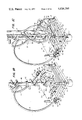
- FIGS. 1-1E are semi-diagrammatic perspective views illustrating an underwater wellhead assembly constructed according to one apparatus embodiment and assembled according to one method embodiment of the invention, the figures being sequential, progressing from illustration of the permanent base, in FIG. 1, to illustration of the completed assembly, in FIG. 1E;
- FIG. 2 is a fragmentary view, partly in vertical cross-section and partly in side elevation, illustrating the relationship between the flowline base assembly and the christmas tree assembly of the installation of FIG. 1E, before the flowlines have been connected to the flowloops of the christmas tree assembly;
- FIG. 3 is a longitudinal sectional view of the swivel employed in the apparatus of FIGS. 1-2;
- FIGS. 4-4D are semi-diagrammatic perspective views illustrating an underwater wellhead assembly constructed and assembled according to another embodiment of the invention, the figures being sequential, progressing from landing of the flowline base, in FIG. 1, to the completed assembly, in FIG. 4D;
- FIG. 5 is a perspective view of an assembled underwater wellhead assembly according to a further embodiment of the invention.
- FIG. 6 is a fragmentary longitudinal sectional view illustrating details of a stinger type connection for the swivel employed in the apparatus of FIG. 5.
- FIGS. 1-3 illustrate the invention as applied to connection of flowlines 1 and 2, FIG. 1E, to the flowloops 3 and 4, respectively, in a dual string production wellhead assembly which is installed at the bottom of the sea or other body of water, at depth too great for diver assistance, by operations carried out remotely from an operational base, typically an offshore drilling vessel (not shown) with the aid of guide means such as the four guide lines 5, FIG. 1, which extend downwardly from the operational base to the wellhead installation.
- Suitable guide means, and the manner in which they are used, are disclosed for example in U.S. Pat. No. 2,808,229, issued Oct. 1, 1967, to Bauer et al. As seen in FIG.
- the installation typically comprises a production body 6 installed conventionally on outer casing 7 and presenting a transverse annular outer locking groove 8 for attachment of the christmas tree as later described.
- a conventional permanent guide base is secured to the outer casing below body 6.
- Guide base 9 is in the nature of a heavy, rigid frame which extends horizontally, is of rectangular shape and is centered with respect to body 6.
- Four upright locator posts 10-10c are included, each located at a different one of the corners of the frame of base 9 and each connected conventionally to a different one of the four guide lines 5.
- the flowline base assembly 12 comprises a main frame 13 which is similar in plan to guide base 9 but slightly smaller, as shown, each corner of the main frame being equipped with a rigidly secured upright guide and locator tube 14, the tubes 14 being positioned to cooperate with locator posts.
- each tube 14 is placed about a different one of the four guide lines 5 and the flowline base assembly is lowered along the guide lines, using conventional handling tools, until the tubes 14 engage respectively over the locator posts 10 and the flowline base assembly is fully landed on the permanent guide base.
- the flowline base assembly has a circular opening 15 dimensioned to accommodate the upper end of the outer casing 7.
- the main frame 13 of flowline base assembly 12 comprises a lower structure 16 which is complete and rigid throughout the entire rectangular plan area of the flowline base assembly, and an upper structure 17 which defines an upwardly opening, horizontally extending recess 19 of generally squared U shape, the two arms of the U of recess 19 extending each on a different side of opening 15.
- Assembly 12 also comprises a secondary frame 20 which corresponds in plan shape to that of the recess 19 and is disposed therein. Recess 19 opens outwardly through one side of upper structure 17, as shown.
- the length of the legs of the U of secondary frame 20 is less than that of the legs of the U of recess 19 so that, when the outer edge of the U of the secondary frame is aligned above the corresponding side edge of lower structure 16, there are substantial spaces between the ends of the legs of frame 20 and the ends of the legs of recess 19.
- Secondary frame 20 is mounted on main frame 13 in such fashion that the secondary frame can be shifted rectilinearly in both directions parallel to the legs of the U of recess 19, between a first position (FIGS.
- lower structure 16 of main frame 13 comprises a plurality of parallel horizontal beams 25 located beneath the area occupied by the secondary frame, beams 25 being equipped with corrosion resistant upper surface members 26, FIG. 2, and the secondary frame being seated directly on members 26 and thus supported by beams 25.
- the structural members defining sides 27 of the legs of the U of recess 19 carry corrosion resistant surface members which are disposed in free sliding engagement with like surface members on the structural members which define the sides 28 of the legs of the secondary frame 20.
- Power devices 29 Housed within upper structure 17 of main frame 13, and rigidly mounted on frame 13, are two rectilinear power devices 29 of any conventional type suitable for moving secondary frame 20 between its two extreme positions in response to control actions taken at the operational base at the water surface.
- Power devices 29 can be fluid pressure operated, e.g., hydraulically operated, piston-and-cylinder devices, with the cylinders 30 mounted on main frame 13 each in a location at the end of and aligned with a different one of the legs of the U of recess 19, the piston rods 31 extending toward the respective ends of the legs of secondary frame 20 with the free ends of the piston rods being pivotally connected to the ends of the legs of the secondary frame.
- Power devices 29 are so constructed and arranged that, upon remote operation of the power devices to extend piston rods 31, secondary frame 20 is shifted outwardly and located precisely at its predetermined first position, with locator posts 24 then occupying predetermined positions relative to the locator posts of permanent guide base 9.
- Tree frame 34 is a unitary rigid structure of a plan shape to overlie one half of permanent guide base 9, yet rigidly support the remotely operated connector 36 which constitutes the bottom of tree assembly 33.
- frame 34 has a straight outer side 37 extending between locator tubes 38 and 38a which are built into the frame at respective locations proper to coact with the two guide lines 5 connected to locator posts 10 and 10a of the permanent guide base.
- the retrievable guide unit 35 is of generally U-shaped plan configuration and is a rigid structure including members 39, forming the legs of the U of the guide unit, and member 40, which forms the base of the U.
- Guide and locator tubes 41 and 41a are mounted rigidly on unit 35, each at a different end of member 40, and are so positioned as to cooperate respectively with guide posts 10b and 10c and the guide lines 5 connected to those guide posts.
- the free ends of members 39 overlap frame 34 and are releasably but rigidly secured thereto in any conventional fashion.
- frame 34 can be equipped with two upright posts 42, FIG.
- the connector 36 can then be locked up by remote operation to secure the tree to body 6, and guide unit 35 can then be disconnected from frame 34 by applying an upward strain with suitable handling tools, the guide unit 35 being withdrawn to the surface, leaving secondary frame 20 of flowline base assembly 12 completely exposed for further operations carried out from above.
- frame 34 has two aligned side portions 45 which each extend radially relative to connector 36.
- frame 34 includes a horizontally offset portion 46 which projects outwardly from the side of the frame defined by portions 45, so that the frame can define a circular opening accommodating portion 36a of the connector.
- Connector 36 can be of the type disclosed in U.S. Pat. No. 3,228,715, issued Jan. 11, 1966, to Neilon et al. and is rigidly secured to frame 34.
- the dimension of frame 34 along the side defined by portions 45 is greater than the corresponding width of the permanent guide base 9. Accordingly, portions 47, FIG. 1B, of frame 34 extend beyond the guide base.
- Flowloops 3 and 4 each have one end connected to the diverter spool 48 of the christmas tree, as indicated at 3a and 4a respectively, and extend arcuately in such fashion that the other ends 3b and 4b of the flowloops are located each above a different one of the overhanging portions 47 of frame 34 and extend horizontally toward the location of secondary frame 20.
- Flowloop end portions 3b and 4b are mutually parallel and each end portion is connected to the female unit 49 of a different one of two remotely operated connectors 50 which are rigidly mounted on frame 34, as by brackets 51.
- Connector units 49 are so arranged that the cavities they define constitute horizontal extensions of the repective flowloop ends, the central axes of the connector units 49 lying in the same horizontal plane.
- Connectors 50 can be miniaturized versions of that disclosed in U.S. Pat. No. 3,228,715.
- Assembly 55 comprises a swivel frame 56, a swivel 57 and the male units 58 of connectors 50, connector units 58 being in the nature of stingers rigidly supported on frame 56, as by brackets 59.
- Frame 56 is in the form of a flat, rigid main structure 60 having straight side edge portions 61 respectively opposed to side portions 45 of frame 34, a notch 62 being provided to accommodate the offset portion 46 of frame 34.
- Releasably attached to frame 56, in the manner hereinbefore described with reference to guide unit 35, is a retrievable guide unit 63, FIG.
- locator tubes 64 and 64a which are so arranged as to cooperate with locator posts 10b and 10c of permanent guide base 9 and with guide lines 5 connected to those posts.
- locator and connector members 65 FIG. 2 are rigidly secured to structure 60 of frame 56 and are so located that, when locator tubes 64, 64a engage over posts 10b and 10c, respectively, each of the members 65 engages over a different one of the locator posts 24 on secondary frame 20 of the flowline base assembly.
- swivel 57 comprises a rotary block 66, FIG.
- rotary block 66 has an axial bore 73 of a diameter somewhat larger than the outer diameter of flowlines 1 and 2, bore 73 being provided with transverse annular grooves 74 which accommodate O-rings 75, or other suitable seals.
- each bore 73 opens into a bore 76 which in turn joins a bore 77, the latter opening outwardly through wall 78 of notch 79.
- Each bore 77 extends at an acute angle x to the axis of block 66.
- End plate 80 has a flat circular main body 82, a centrally disposed right cylindrical tubular extension 83, and a tubular hub 84 which is coaxial with extension 83 and located on the side of body 82 opposite the extension.
- An axial bore 85 extends centrally through extension 83, body 82 and hub 84. Through extension 83 and a portion of main body 82, bore 85 has a diameter equal to the diameter of bore portions 76 and 77 and flowlines 1 and 2.
- the diameter of bore 85 is enlarged to accomodate one end portion of tube 86 which is identical to flowlines 1 and 2, tube 86 being inserted into hub 84 and secured by weld 87.
- End plate 80 is secured to bracket 71, as by cap screws 88.
- Tubes 86 entend horizontally and are curved through 90°, as seen in FIG. 1C, so that the ends 87 thereof opposite the swivel lie in a common plane, are mutually parallel, and open toward the tree 34 after assembly 55 has been landed. Ends 87 are each connected to a different one of the male connector units 58.
- the positions of brackets 59 are such that, when the swivel assembly has been landed, with connector members 65 locked to locator posts 24, each unit 58 is aligned coaxially with a different one of the female connector units 49. As seen in FIG.
- stingers 58 project beyond side portions 61 of frame structure 60, and female connector units 49 similarly project beyond side portions 45 of tree frame 34 so that, when power devices 29 are operated to move secondary frame 20 toward tree frame 34, stingers 58 are inserted positively and fully into connector units 49. the connectors 50 then being locked by remote control. Connectors 50 can be unlocked by remote operation so that secondary frame 20 can be moved back to the right (as viewed in FIG. 2) to withdraw stingers 58 preparatory to independent recovery of either christmas tree assembly 32 or swivel assembly 55.
- Connector members 65 and locator posts 24 coact not only for accurate location of swivel frame 56 on secondary frame 20 but also as releasable lock means to secure the swivel assembly to the secondary frame.
- each post 24 can be provided with a transverse locking groove to cooperate with spring urged shearable latch members carried by connector members 65, in the manner disclosed in U.S. Pat. No. 3,268,239.
- a counterbore 94 is provided through wall 78 to accommodate the end portions of the respective flowlines, the flowline ends being rigidly secured to swivel block 66 by welds 95.
- the flowline end portions are coaxial with the respective bore portions 77 so as to extend initially outwardly and away from the swivel block as the acute angle x.
- flowlines 1 and 2 then curve arcuately away from the swivel and then extend along a line transverse to the axis of rotation of the swivel so that, within a distance of a few feet from the swivel, the flowlines extend side-by-side in mutually parallel, closely spaced relation.
- the flowlines are mechanically joined by a straight cross-brace 96, FIG. 1C, and parallel longitudinal stiffening braces 97 are also provided, each extending from a different end of cross-brace 96 to swivel block 66. Braces 96 and 97 are welded in place.
- the swivel assembly 55 is made up on the operational base at the water surface, including installation of block 66 to which flowlines 1 and 2 have been attached. As seen in FIG. 1C, landing of the swivel assembly is accomplished with secondary frame 20 in its outer-most position and with flowlines 1 and 2 extending upwardly to the operational base. When the swivel assembly is first landed, piston rods 31 are extended and stingers 58 are therefore spaced from female connector units 49. The next step of the method is to operate power devices 29 to shift secondary frame 20 inwardly, causing stingers 58 to be inserted in connector units 49, connectors 50 then being locked remotely, the flowline base assembly and the swivel assembly now being in the positions seen in FIG. 1D.
- flowlines 1 and 2 are connected respectively to flowloops 3 and 4 via swivel block 66, tubes 86, and connectors 50 and that such connection has been accomplished without requiring flexing of the flowloops and without creating any internal recesses which might interfere with travel of pump-down tools along the flow paths.
- swivel block 66 tubes 86, and connectors 50
- FIG. 3 it will be understood that, for each flowline, a part of the flow path, established by tube 86 and bore 85, is coaxial with the axis of rotation of swivel 57, and that the swivel is completely free to turn without having any affect on the ability of the flow paths to conduct fluid between the well and the flowlines.
- the final step of the method is to lay the flowlines 1 and 2 out along the bottom of the body of water, this being accomplished, e.g., by moving a lay barge (not shown) away from the operational base while paying out the flowlines.
- swivel block 66 rotates about the axis determined by bearings 69 and 70, such rotation being caused by movement of the flowlines and continuing until the flowlines are at rest on the bottom of the body of water and the portions of the flowlines adjacent the wellhead assembly have assumed a natural catenary determined inherently by the characteristics of the flowlines, the elevation of swivel 57 above the bottom, and the configuration of the bottom adjacent the installation.
- FIGS. 4-4D illustrate the invention as applied to an underwater well installation of the type in which the dual string wellhead is not adapted for pump-down tools.
- the permanent guide base 109 is identical to guide base 9, FIG. 1 and is installed conventionally.
- Flowline base assembly 112 includes a main frame 113 and a simple rectangular secondary frame 120 shiftable on the main frame within a rectangular recess 119 wholly at one side of the surface casing, power devices (not shown) being provided, for shifting secondary frame 120, as hereinbefore described with reference to power devices 29 of the embodiment of FIGS. 1-3.
- Both main frame 113 and secondary frame 120 are provided with outwardly opening notches 113a and 120a, respectively, to provide increased clearance for flowlines 101, 102.
- Secondary frame 120 is equipped with only two locator posts 124.
- the christmas tree assembly 132 includes simple flow branches 103 and 104, each terminating in the female connector unit 149 of a different one of two connectors 150, units 149 being rigidly mounted on the main body 134a of tree frame 134.
- the tree frame includes two arms 135 each carrying a diffferent one of locator tubes 141 and 141a, it thus being unnecessary in this embodiment to employ the retrievable two-arm guide unit of the flowline base assembly of FIGS. 1-3.
- the swivel assembly 155 comprises a swivel 157, a retrievable guide unit (not shown) carrying locator tubes to cooperate with guideposts 110b and 110c, stingers 158, and tubes 186 interconnecting the swivel and the stingers.
- Swivel assembly 155 carries dependent connectors 165, equivalent to connectors 65, FIG. 2, for cooperating with locator posts 124 to secure the swivel assembly to secondary frame 120.
- Swivel block 166 turns freely about its axis and defines flow ducts coaxial with its axis of rotation. Flowlines 101 and 102 are connected at right angles to the swivel block, the flow ducts in the block turning at right angles since passage of pump-down tools is not required. Installation is generally as described with reference to the embodiment of FIGS. 1-3.
- the swivel assembly 255 includes two pivot blocks 249 arranged each at different end of the swivel 257 and each constructed to receive a stinger 258, FIG. 6, arranged for rectilinear movement in a stinger block 300.
- Stinger blocks 300 are rigidly mounted on christmas tree frame 234 and are spaced apart in coaxial alignment.
- Pivot blocks 249 are rigidly secured to a carried member 249a located on the side of the blocks nearer the flow unit assembly 232.
- Each block 249 is secured rigidly to one of two dependent locator tubes 265, tubes 265 being spaced apart by a distance such that, when the swivel assembly is lowered down the usual guide means (not shown) connected to the locator posts 210-210c, FIG. 5, each tube 265 telescopes downwardly over a different one of the two locator posts 224 carried by flowline base assembly 212, and pivot blocks 249 of the swivel assembly are thus accurately positioned relative to the stinger blocks 300.
- Stingers 258 are disposed as pistons in the respective blocks 300 so that, once the swivel assembly has been landed, stingers 258 can be hydraulically actuated simultaneously to their engaged positions, seen in FIG. 6, in the respective pivot blocks 249.
- Each stinger 258, as seen in FIG. 6, comprises a right cylindrical body 301 having an integral portion 302 of enlarged diameter intermediate portion 303 cooperating as a piston with cylinder portion 304 of block 300.
- the effective length of cylinder portion 304 is defined by a transverse annular inwardly projecting shoulder 305 of block 300, on the one hand, and a sleeve 306, on the other hand, sleeve 306 being inserted in the outer end of the bore of block 300 and secured by threads, as shown.
- Ports 307 are provided at the respective ends of cylinder portion 304 for connection to conduits (not shown) for the supply and exhaust of hydraulic fluid under control from the operational base, such as a vessel (not shown) at the surface of the body of water
- Portion 258a of the stinger projects from piston portion 302 toward the end of the block 300 which accommodates sleeve 306.
- Portion 258a has a diameter such as to be slidably accommodated in sleeve 306, and seals are provided at 308 to seal between portion 258a and sleeve 306.
- Portion 258b of the stinger projects from piston portion 302 toward the adjacent pivot block 249 (when swivel assembly 255 has been installed).
- Pivot block 249 has a through bore 309 which is coaxial with the bore of stinger block 300 in the final installation, and bore 309 accommodates a sleeve 310 which serves both as a bushing in which the tubular stub shaft 311 of swivel 257 is journalled and as a receptacle to receive stinger portion 258b.
- Stinger portion 258b is equipped with seals at 312 to seal between stinger portion 258b and sleeve 310.
- stinger portion 258b has a short portion 313 to be accommodated by the bore of stub shaft 311, as shown in FIG. 6.
- Piston portion 302 is provided with seals at 314 to seal between that portion and cylinder portion 304.
- Stinger 258 has a through bore 315.
- the bore of stub shaft 311 continues through the body of swivel 257 to communicate with the corresponding one of flowlines 201, 202.
- a flanged tubing connector 316, FIG. 6, is bolted to the end of stinger block 300 which accommodates sleeve 306, placing conduit 286 in communication with stinger bore 315.
- installation is accomplished by a method in which the flowline is attached to a swivel which has a flow passage which is coaxial with the axis of rotation of the swivel and with which the connected end of the flowline communicates, lowering to a predetermined position at the underwater installation a flow unit (such as the christmas tree) having a conduit terminating in a connector with which the flowline is to communicate, lowering the swivel, with flowline attached, into a predetermined position relative to the connector, remotely connecting the swivel to the connector so that the flow unit conduit is in communication with the flowline via the passage in the swivel, and then laying out the flowline, the swivel turning freely to the final position determined by the attached end of the flowline.
- a flow unit such as the christmas tree
Abstract
Description
Claims (14)
Priority Applications (2)
| Application Number | Priority Date | Filing Date | Title |
|---|---|---|---|
| US05/679,226 US4036295A (en) | 1976-04-22 | 1976-04-22 | Method and apparatus for connecting flowlines to underwater installations |
| GB16830/77A GB1515830A (en) | 1976-04-22 | 1977-04-22 | Method and apparatus for connecting flowlines to underwater installations |
Applications Claiming Priority (1)
| Application Number | Priority Date | Filing Date | Title |
|---|---|---|---|
| US05/679,226 US4036295A (en) | 1976-04-22 | 1976-04-22 | Method and apparatus for connecting flowlines to underwater installations |
Publications (1)
| Publication Number | Publication Date |
|---|---|
| US4036295A true US4036295A (en) | 1977-07-19 |
Family
ID=24726073
Family Applications (1)
| Application Number | Title | Priority Date | Filing Date |
|---|---|---|---|
| US05/679,226 Expired - Lifetime US4036295A (en) | 1976-04-22 | 1976-04-22 | Method and apparatus for connecting flowlines to underwater installations |
Country Status (2)
| Country | Link |
|---|---|
| US (1) | US4036295A (en) |
| GB (1) | GB1515830A (en) |
Cited By (22)
| Publication number | Priority date | Publication date | Assignee | Title |
|---|---|---|---|---|
| US4120362A (en) * | 1976-11-22 | 1978-10-17 | Societe Nationale Elf Aquitaine (Production) | Subsea station |
| US4190114A (en) * | 1978-08-18 | 1980-02-26 | Cameron Iron Works, Inc. | Subsea wellhead apparatus |
| US4194857A (en) * | 1976-11-22 | 1980-03-25 | Societe Nationale Elf Aquitaine (Production) | Subsea station |
| US4260022A (en) * | 1978-09-22 | 1981-04-07 | Vetco, Inc. | Through the flow-line selector apparatus and method |
| US4274664A (en) * | 1977-08-05 | 1981-06-23 | Compagnie Francaise Des Petroles | Pipe joining device for underseas petroleum pipeline |
| US4294471A (en) * | 1979-11-30 | 1981-10-13 | Vetco Inc. | Subsea flowline connector |
| US4311327A (en) * | 1979-12-20 | 1982-01-19 | Exxon Production Research Company | Universal joint for multiple flowline system |
| US4337970A (en) * | 1979-12-20 | 1982-07-06 | Exxon Production Research Company | Universal joint for multiple conduit system |
| FR2520436A1 (en) * | 1982-01-28 | 1983-07-29 | Mobil Oil Corp | UNDERWATER WELL HEAD CONNECTION GROUP AND METHOD OF INSTALLATION |
| US4438817A (en) * | 1982-09-29 | 1984-03-27 | Armco Inc. | Subsea well with retrievable piping deck |
| FR2554542A1 (en) * | 1983-11-09 | 1985-05-10 | Wiederaufarbeitung Von Kernbre | CONDUIT COMMUNICATION DEVICE FOR CONNECTING FIXED PIPE FITTINGS |
| US4661017A (en) * | 1985-03-29 | 1987-04-28 | Exxon Production Research Co. | Method and apparatus for aligning underwater components |
| US4832124A (en) * | 1985-01-03 | 1989-05-23 | Texaco Ltd | Subsea well head template |
| WO1998049422A1 (en) * | 1997-04-29 | 1998-11-05 | Fmc Corporation | Apparatus and method for subsea connections of trees to subsea wellheads |
| US6142708A (en) * | 1999-05-19 | 2000-11-07 | Oil States Industries Inc. | Rotating porch for subsea branch and termination pipeline connections |
| US20120160505A1 (en) * | 2009-09-16 | 2012-06-28 | Loennemo Ulf | Load transferring subsea structure |
| US20130098626A1 (en) * | 2011-10-20 | 2013-04-25 | Vetco Gray Inc. | Soft Landing System and Method of Achieving Same |
| EP2746530A1 (en) * | 2012-12-21 | 2014-06-25 | Vetco Gray Scandinavia AS | Subsea arrangement |
| US9670755B1 (en) * | 2011-06-14 | 2017-06-06 | Trendsetter Engineering, Inc. | Pump module systems for preventing or reducing release of hydrocarbons from a subsea formation |
| US20180066771A1 (en) * | 2015-03-03 | 2018-03-08 | Aker Solutions As | Connection system for subsea pipelines |
| NO20200699A1 (en) * | 2019-11-13 | 2021-05-14 | Fmc Kongsberg Subsea As | A module, a system and a method for daisy chaining of satellite wells |
| WO2021094580A1 (en) | 2019-11-13 | 2021-05-20 | Fmc Kongsberg Subsea As | A module, a system and a method for daisy chaining of satellite wells |
Citations (5)
| Publication number | Priority date | Publication date | Assignee | Title |
|---|---|---|---|---|
| US3308881A (en) * | 1962-11-05 | 1967-03-14 | Chevron Res | Method and apparatus for offshore well completion |
| US3373807A (en) * | 1966-06-06 | 1968-03-19 | Chevron Res | Underwater pipeline connecting method and apparatus |
| US3490792A (en) * | 1968-08-08 | 1970-01-20 | Welding & Steel Fabrication Co | Quick disconnect |
| US3492027A (en) * | 1968-03-11 | 1970-01-27 | Rockwell Mfg Co | Remote connection release |
| US3968838A (en) * | 1973-08-07 | 1976-07-13 | Vetco Offshore Industries, Inc. | Underwater connection apparatus |
-
1976
- 1976-04-22 US US05/679,226 patent/US4036295A/en not_active Expired - Lifetime
-
1977
- 1977-04-22 GB GB16830/77A patent/GB1515830A/en not_active Expired
Patent Citations (5)
| Publication number | Priority date | Publication date | Assignee | Title |
|---|---|---|---|---|
| US3308881A (en) * | 1962-11-05 | 1967-03-14 | Chevron Res | Method and apparatus for offshore well completion |
| US3373807A (en) * | 1966-06-06 | 1968-03-19 | Chevron Res | Underwater pipeline connecting method and apparatus |
| US3492027A (en) * | 1968-03-11 | 1970-01-27 | Rockwell Mfg Co | Remote connection release |
| US3490792A (en) * | 1968-08-08 | 1970-01-20 | Welding & Steel Fabrication Co | Quick disconnect |
| US3968838A (en) * | 1973-08-07 | 1976-07-13 | Vetco Offshore Industries, Inc. | Underwater connection apparatus |
Cited By (30)
| Publication number | Priority date | Publication date | Assignee | Title |
|---|---|---|---|---|
| US4120362A (en) * | 1976-11-22 | 1978-10-17 | Societe Nationale Elf Aquitaine (Production) | Subsea station |
| US4194857A (en) * | 1976-11-22 | 1980-03-25 | Societe Nationale Elf Aquitaine (Production) | Subsea station |
| US4274664A (en) * | 1977-08-05 | 1981-06-23 | Compagnie Francaise Des Petroles | Pipe joining device for underseas petroleum pipeline |
| US4190114A (en) * | 1978-08-18 | 1980-02-26 | Cameron Iron Works, Inc. | Subsea wellhead apparatus |
| US4260022A (en) * | 1978-09-22 | 1981-04-07 | Vetco, Inc. | Through the flow-line selector apparatus and method |
| US4294471A (en) * | 1979-11-30 | 1981-10-13 | Vetco Inc. | Subsea flowline connector |
| US4311327A (en) * | 1979-12-20 | 1982-01-19 | Exxon Production Research Company | Universal joint for multiple flowline system |
| US4337970A (en) * | 1979-12-20 | 1982-07-06 | Exxon Production Research Company | Universal joint for multiple conduit system |
| FR2520436A1 (en) * | 1982-01-28 | 1983-07-29 | Mobil Oil Corp | UNDERWATER WELL HEAD CONNECTION GROUP AND METHOD OF INSTALLATION |
| US4438817A (en) * | 1982-09-29 | 1984-03-27 | Armco Inc. | Subsea well with retrievable piping deck |
| FR2554542A1 (en) * | 1983-11-09 | 1985-05-10 | Wiederaufarbeitung Von Kernbre | CONDUIT COMMUNICATION DEVICE FOR CONNECTING FIXED PIPE FITTINGS |
| US4634150A (en) * | 1983-11-09 | 1987-01-06 | Deutsche Gesellschaft Fur Wiederaufarbeitung Von Kernbrennstoffen Mbh | Conduit arrangement for interconnecting stationary conduit extensions |
| US4832124A (en) * | 1985-01-03 | 1989-05-23 | Texaco Ltd | Subsea well head template |
| US4661017A (en) * | 1985-03-29 | 1987-04-28 | Exxon Production Research Co. | Method and apparatus for aligning underwater components |
| WO1998049422A1 (en) * | 1997-04-29 | 1998-11-05 | Fmc Corporation | Apparatus and method for subsea connections of trees to subsea wellheads |
| US5868203A (en) * | 1997-04-29 | 1999-02-09 | Fmc Corporation | Apparatus and method for subsea connections of trees to subsea wellheads |
| US6142708A (en) * | 1999-05-19 | 2000-11-07 | Oil States Industries Inc. | Rotating porch for subsea branch and termination pipeline connections |
| US20120160505A1 (en) * | 2009-09-16 | 2012-06-28 | Loennemo Ulf | Load transferring subsea structure |
| US10060555B2 (en) * | 2009-09-16 | 2018-08-28 | Apply Nemo As | Load transferring subsea structure |
| US9670755B1 (en) * | 2011-06-14 | 2017-06-06 | Trendsetter Engineering, Inc. | Pump module systems for preventing or reducing release of hydrocarbons from a subsea formation |
| US20130098626A1 (en) * | 2011-10-20 | 2013-04-25 | Vetco Gray Inc. | Soft Landing System and Method of Achieving Same |
| US8931561B2 (en) * | 2011-10-20 | 2015-01-13 | Vetco Gray Inc. | Soft landing system and method of achieving same |
| US9347292B2 (en) | 2011-10-20 | 2016-05-24 | Vetco Gray Inc. | Soft landing system and method of achieving same |
| US9228677B2 (en) | 2012-12-21 | 2016-01-05 | Vetco Gray Scandinavia.As | Subsea arrangement |
| EP2746530A1 (en) * | 2012-12-21 | 2014-06-25 | Vetco Gray Scandinavia AS | Subsea arrangement |
| US20180066771A1 (en) * | 2015-03-03 | 2018-03-08 | Aker Solutions As | Connection system for subsea pipelines |
| US10465822B2 (en) * | 2015-03-03 | 2019-11-05 | Aker Solutions As | Connection system for subsea pipelines |
| NO20200699A1 (en) * | 2019-11-13 | 2021-05-14 | Fmc Kongsberg Subsea As | A module, a system and a method for daisy chaining of satellite wells |
| WO2021094580A1 (en) | 2019-11-13 | 2021-05-20 | Fmc Kongsberg Subsea As | A module, a system and a method for daisy chaining of satellite wells |
| US11840907B2 (en) | 2019-11-13 | 2023-12-12 | Fmc Kongsberg Subsea As | Module, a system and a method for daisy chaining of satellite wells |
Also Published As
| Publication number | Publication date |
|---|---|
| GB1515830A (en) | 1978-06-28 |
Similar Documents
| Publication | Publication Date | Title |
|---|---|---|
| US4036295A (en) | Method and apparatus for connecting flowlines to underwater installations | |
| US3710859A (en) | Apparatus for remotely connecting and disconnecting pipe lines to and from a submerged wellhead | |
| US6497286B1 (en) | Method and apparatus for drilling a plurality of offshore underwater wells | |
| US6742594B2 (en) | Flowline jumper for subsea well | |
| US7032673B2 (en) | Orientation system for a subsea well | |
| US4192383A (en) | Offshore multiple well drilling and production apparatus | |
| US4427072A (en) | Method and apparatus for deep underwater well drilling and completion | |
| US6481504B1 (en) | Flowline connector with subsea equipment package | |
| US3604731A (en) | Simultaneous pipeline-wellhead connections | |
| US4191256A (en) | Subsea flowline connector | |
| US4194857A (en) | Subsea station | |
| US4625806A (en) | Subsea drilling and production system for use at a multiwell site | |
| US5040607A (en) | Production system for subsea oil wells | |
| US3732923A (en) | Remote underwater flowline connection | |
| US4437521A (en) | Subsea wellhead connection assembly and methods of installation | |
| US4067385A (en) | Apparatus and method for connecting a tubing string to downhole well equipment | |
| IE45911B1 (en) | Subsea installation | |
| US4629003A (en) | Guilelineless subsea completion system with horizontal flowline connection | |
| US3041090A (en) | Pivoted tubing well connection | |
| NO151095B (en) | DEVICE FOR CONNECTING A PIPE HANGER WITH LOWER BROWN EQUIPMENT | |
| CA1197180A (en) | Subsea wellhead connection assembly and a method of installing same | |
| US3347312A (en) | Underwater wellhead installations | |
| US3500904A (en) | Marine conductor pipe | |
| JPS6095094A (en) | Ocean pit opening connecting apparatus | |
| USRE27340E (en) | Connector for underwater pipelines |
Legal Events
| Date | Code | Title | Description |
|---|---|---|---|
| AS | Assignment |
Owner name: NATIONAL SUPPLY COMPANY, INC., A CORP. OF DE Free format text: ASSIGNMENT OF ASSIGNORS INTEREST.;ASSIGNOR:ARMCO INC;REEL/FRAME:004728/0498 Effective date: 19870327 Owner name: NATIONAL OILWELL, A GENERAL PARTNERSHIP OF DE Free format text: ASSIGNMENT OF ASSIGNORS INTEREST.;ASSIGNOR:NATIONAL SUPPLY COMPANY, INC., A CORP. OF DE;REEL/FRAME:004747/0423 Effective date: 19870403 |
|
| AS | Assignment |
Owner name: CITICORP USA, INC., AS COLLATERAL AGENT, NEW YORK Free format text: SECURITY INTEREST;ASSIGNOR:NATIONAL-OILWELL;REEL/FRAME:006486/0856 Effective date: 19930322 |
|
| AS | Assignment |
Owner name: KVAERNER NATIONAL, INC., TEXAS Free format text: ASSIGNMENT OF ASSIGNORS INTEREST;ASSIGNOR:NATIONAL - OILWELL;REEL/FRAME:006952/0738 Effective date: 19940131 Owner name: NATIONAL-OILWELL, TEXAS Free format text: RELEASE OF SECURITY INTEREST AND COLLATERAL REASSIGNMENT.;ASSIGNOR:CITICORP USA, INC., AS U.S. COLLATERAL AGENT;REEL/FRAME:006952/0762 Effective date: 19940131 |